US7856209B1 - Method and system for location estimation in wireless networks - Google Patents
Method and system for location estimation in wireless networksDownload PDFInfo
- Publication number
- US7856209B1 US7856209B1US11/291,510US29151005AUS7856209B1US 7856209 B1US7856209 B1US 7856209B1US 29151005 AUS29151005 AUS 29151005AUS 7856209 B1US7856209 B1US 7856209B1
- Authority
- US
- United States
- Prior art keywords
- wireless
- wireless device
- location
- starting time
- frame
- Prior art date
- Legal status (The legal status is an assumption and is not a legal conclusion. Google has not performed a legal analysis and makes no representation as to the accuracy of the status listed.)
- Active, expires
Links
- 238000000034methodMethods0.000titleclaimsabstractdescription126
- 238000012545processingMethods0.000claimsabstractdescription35
- 230000000694effectsEffects0.000description23
- 230000005540biological transmissionEffects0.000description18
- 230000008569processEffects0.000description17
- 230000006870functionEffects0.000description16
- 238000012986modificationMethods0.000description15
- 230000004048modificationEffects0.000description15
- 238000001514detection methodMethods0.000description14
- 230000004044responseEffects0.000description14
- 238000005094computer simulationMethods0.000description12
- 239000000523sampleSubstances0.000description11
- 238000007796conventional methodMethods0.000description9
- 238000010586diagramMethods0.000description9
- 230000006855networkingEffects0.000description9
- 238000005242forgingMethods0.000description8
- 238000005259measurementMethods0.000description8
- 239000000463materialSubstances0.000description7
- 230000008901benefitEffects0.000description6
- 238000004891communicationMethods0.000description6
- 238000005516engineering processMethods0.000description6
- 238000004458analytical methodMethods0.000description4
- 230000001413cellular effectEffects0.000description4
- 238000001914filtrationMethods0.000description4
- 238000001228spectrumMethods0.000description4
- 238000004590computer programMethods0.000description3
- 229920001690polydopaminePolymers0.000description3
- 238000012360testing methodMethods0.000description3
- 239000011449brickSubstances0.000description2
- 239000003086colorantSubstances0.000description2
- 238000011960computer-aided designMethods0.000description2
- 239000011521glassSubstances0.000description2
- 230000002265preventionEffects0.000description2
- 230000005855radiationEffects0.000description2
- 230000001105regulatory effectEffects0.000description2
- 239000011435rockSubstances0.000description2
- 238000007476Maximum LikelihoodMethods0.000description1
- 241001105470ValenzuelaSpecies0.000description1
- 230000009471actionEffects0.000description1
- 238000013459approachMethods0.000description1
- 238000010420art techniqueMethods0.000description1
- 230000015556catabolic processEffects0.000description1
- 230000008859changeEffects0.000description1
- 238000004883computer applicationMethods0.000description1
- 238000006731degradation reactionMethods0.000description1
- 230000007613environmental effectEffects0.000description1
- 230000007246mechanismEffects0.000description1
- 239000002184metalSubstances0.000description1
- 239000000203mixtureSubstances0.000description1
- 238000012544monitoring processMethods0.000description1
- 230000003287optical effectEffects0.000description1
- 238000005192partitionMethods0.000description1
- 238000011002quantificationMethods0.000description1
- 230000000246remedial effectEffects0.000description1
- 238000000926separation methodMethods0.000description1
- 230000008054signal transmissionEffects0.000description1
- 238000004088simulationMethods0.000description1
- 238000000060site-specific infrared dichroism spectroscopyMethods0.000description1
- 230000000007visual effectEffects0.000description1
- 238000012800visualizationMethods0.000description1
- 239000002023woodSubstances0.000description1
Images


Classifications
- H—ELECTRICITY
- H04—ELECTRIC COMMUNICATION TECHNIQUE
- H04L—TRANSMISSION OF DIGITAL INFORMATION, e.g. TELEGRAPHIC COMMUNICATION
- H04L63/00—Network architectures or network communication protocols for network security
- H04L63/14—Network architectures or network communication protocols for network security for detecting or protecting against malicious traffic
- H04L63/1408—Network architectures or network communication protocols for network security for detecting or protecting against malicious traffic by monitoring network traffic
- G—PHYSICS
- G01—MEASURING; TESTING
- G01S—RADIO DIRECTION-FINDING; RADIO NAVIGATION; DETERMINING DISTANCE OR VELOCITY BY USE OF RADIO WAVES; LOCATING OR PRESENCE-DETECTING BY USE OF THE REFLECTION OR RERADIATION OF RADIO WAVES; ANALOGOUS ARRANGEMENTS USING OTHER WAVES
- G01S5/00—Position-fixing by co-ordinating two or more direction or position line determinations; Position-fixing by co-ordinating two or more distance determinations
- G01S5/02—Position-fixing by co-ordinating two or more direction or position line determinations; Position-fixing by co-ordinating two or more distance determinations using radio waves
- G01S5/0295—Proximity-based methods, e.g. position inferred from reception of particular signals
- H—ELECTRICITY
- H04—ELECTRIC COMMUNICATION TECHNIQUE
- H04W—WIRELESS COMMUNICATION NETWORKS
- H04W12/00—Security arrangements; Authentication; Protecting privacy or anonymity
- H04W12/12—Detection or prevention of fraud
- H—ELECTRICITY
- H04—ELECTRIC COMMUNICATION TECHNIQUE
- H04W—WIRELESS COMMUNICATION NETWORKS
- H04W12/00—Security arrangements; Authentication; Protecting privacy or anonymity
- H04W12/12—Detection or prevention of fraud
- H04W12/121—Wireless intrusion detection systems [WIDS]; Wireless intrusion prevention systems [WIPS]
- H04W12/122—Counter-measures against attacks; Protection against rogue devices
- H—ELECTRICITY
- H04—ELECTRIC COMMUNICATION TECHNIQUE
- H04W—WIRELESS COMMUNICATION NETWORKS
- H04W64/00—Locating users or terminals or network equipment for network management purposes, e.g. mobility management
- H—ELECTRICITY
- H04—ELECTRIC COMMUNICATION TECHNIQUE
- H04L—TRANSMISSION OF DIGITAL INFORMATION, e.g. TELEGRAPHIC COMMUNICATION
- H04L63/00—Network architectures or network communication protocols for network security
- H04L63/14—Network architectures or network communication protocols for network security for detecting or protecting against malicious traffic
- H04L63/1441—Countermeasures against malicious traffic
- H04L63/1466—Active attacks involving interception, injection, modification, spoofing of data unit addresses, e.g. hijacking, packet injection or TCP sequence number attacks
- H—ELECTRICITY
- H04—ELECTRIC COMMUNICATION TECHNIQUE
- H04W—WIRELESS COMMUNICATION NETWORKS
- H04W12/00—Security arrangements; Authentication; Protecting privacy or anonymity
- H04W12/06—Authentication
- H—ELECTRICITY
- H04—ELECTRIC COMMUNICATION TECHNIQUE
- H04W—WIRELESS COMMUNICATION NETWORKS
- H04W12/00—Security arrangements; Authentication; Protecting privacy or anonymity
- H04W12/08—Access security
- H—ELECTRICITY
- H04—ELECTRIC COMMUNICATION TECHNIQUE
- H04W—WIRELESS COMMUNICATION NETWORKS
- H04W12/00—Security arrangements; Authentication; Protecting privacy or anonymity
- H04W12/60—Context-dependent security
- H04W12/63—Location-dependent; Proximity-dependent
- H—ELECTRICITY
- H04—ELECTRIC COMMUNICATION TECHNIQUE
- H04W—WIRELESS COMMUNICATION NETWORKS
- H04W84/00—Network topologies
- H04W84/02—Hierarchically pre-organised networks, e.g. paging networks, cellular networks, WLAN [Wireless Local Area Network] or WLL [Wireless Local Loop]
- H04W84/10—Small scale networks; Flat hierarchical networks
- H04W84/12—WLAN [Wireless Local Area Networks]
Definitions
- the present inventionalso relates to U.S. application Ser. No. 10/931,585, filed on Aug. 31, 2004 and U.S. application Ser. No. 10/931,926, filed on Aug. 31, 2004, commonly assigned, and each of which is hereby incorporated by reference for all purposes, each of which claims priority to U.S. Provisional Application No. 60/543,631, entitled “An Automated Method and an RF Sensor System for Wireless Unauthorized Transmission, Intrusion Detection and Prevention,” filed Feb. 11, 2004, commonly assigned, and hereby incorporated by reference for all purposes.
- the present inventionfurther relates to U.S. application Ser. No. 10/931,499, filed on Aug. 31, 2004, commonly assigned, and hereby incorporated by reference for all purposes, which claims priority to U.S.
- This present inventionrelates generally to wireless computer networking techniques. More particularly, the invention provides a method and a system for estimating the physical location of wireless transmitters in wireless networks according to a specific embodiment. Preferably the wireless transmitters are associated with certain undesirable wireless activity such as denial of service attacks, spoofing, address forging and others.
- the inventionhas been applied to a computer networking environment based upon the IEEE 802.11 family of standards, commonly called “WiFi.” But it would be recognized that the invention has a much broader range of applicability.
- the inventioncan be applied to Ultra Wide Band (“UWB”), IEEE 802.16 commonly known as “WiMAX”, cellular wireless networks such as CDMA, GSM, GPRS, and others.
- UWBUltra Wide Band
- WiMAXIEEE 802.16
- cellular wireless networkssuch as CDMA, GSM, GPRS, and others.
- Computer systemshave proliferated from academic and specialized science applications to day to day business, commerce, information distribution and home applications.
- Such systemsinclude personal computers, which are often called “PCs” for short, to large mainframe and server class computers.
- Powerful mainframe and server class computersrun specialized applications for banks, small and large companies, e-commerce vendors, and governments. Smaller personal computers can be found in many if not all offices, homes, and even local coffee shops.
- These computersinterconnect with each other through computer communication networks based on packet switching technology such as the Internet protocol or IP.
- IPInternet protocol
- the computer systems located within a specific local geographic areasuch as an office, home or other indoor and outdoor premises interconnect using a Local Area Network, commonly called, LAN. Ethernet is by far the most popular networking technology for LANs.
- the LANsinterconnect with each other using a Wide Area Network called “WAN” such as the Internet.
- WANWide Area Network
- wireless communication technologieswirelessly connect users to the computer networks.
- wireless networksinclude, but are not limited to, wireless local area networks (WLAN) and cellular networks.
- WLANwireless local area networks
- One desirable application of wireless networksis to provide wireless access to the LAN in the office, the home, public hot-spots, and other geographical locations.
- IEEE 802.11 family of standardscommonly called WiFi
- WiFiis the common standard for such wireless applications.
- WiFithe 802.11b standard-based WiFi often operates at the 2.4
- the 802.11g compliant WiFioffers even faster connectivity at about 54 Mbps and operates at the 2.4 GHz unlicensed radio frequency spectrum.
- the 802.11a standardprovides speeds up to 54 Mbps operating in the 5 GHz unlicensed radio frequency spectrum. WiFi enables a quick and effective way of providing wireless extension to the existing LAN.
- one or more WiFi access pointsconnect to the LAN connection ports either directly or through intermediate equipment such as a WiFi switch.
- a usercan wirelessly connects to the LAN using a device equipped with a WiFi radio, commonly called a wireless station that communicates with the AP.
- the connectionis free from cable and other physical encumbrances and allows the user to “Surf the Web,” check e-mail, or use enterprise and e-commerce computer applications in an easy and efficient manner. Since access points have limited signal coverage, multiple access points may be required to provide signal coverage throughout a facility.
- Another advantage of wireless networksis that wireless stations can move throughout the signal coverage area and continue to connect to the computer network. In a typical operational wireless network, multiple wireless stations operate from different locations within the geographic area comprising the wireless network. Station locations may also change from time to time as the users carrying those devices move.
- Determining the physical location of a wireless station, or that of a signal transmitting device,is useful for many applications, such as dispatching and location based applications.
- Physical location information regarding a wireless stationis critical if said station either deliberately or unknowingly is causing harm to the wireless network in the form of a security breach, intrusion, performance degradation, and the like. Knowing the physical location of the wireless station in these scenarios enables the network administrator to track down the station and take action (e.g., remove it from the vicinity of the network) to avoid a security or performance catastrophe.
- location tracking capabilityis often not supported by standard WiFi communication systems and hence a location tracking solution is highly desirable.
- Prior solutionshave attempted to provide mechanisms to determine the physical location of a wireless station, with varying degrees of success.
- One conventional technique for location determination in local area wireless networking environmentsinvolves triangulating the position of the wireless station with respect to predetermined reference locations, based on signal strength measurements.
- a number of wireless access points or sniffersare provided at reference locations in the region of operation of the local area network. These access points or sniffer devices measure the received signal strength from the transmitting wireless station.
- the signal measurements of various access points or sniffer devicesare collected at a server and the physical location of the station triangulated. Certain factors such as the layout of the region (e.g., walls, doors, roof, and other components that cause signal attenuation and/or reflection) and the statistical variability of the received signal strength can also be considered during triangulation.
- Another conventional technique for location determination in local area wireless networking environmentsinvolves definition of areas within the geographic region of interest. A signal strength signature is then created for each area, representing the received signal strength measured at one or more network access points or sniffers and originating from the device transmitting from the area. During the operation, the area in which a transmitting wireless station resides is determined by comparing with the signal strength signature for various areas, the observed received signal strengths from the transmitting wireless station received at the network access points or sniffers. The comparison can be done via pattern matching.
- the inventionprovides a method and a system for estimating the physical location of wireless transmitters in wireless networks according to a specific embodiment.
- the wireless transmittersare associated with certain undesirable wireless activity such as denial of service attacks, spoofing, address forging and others.
- the inventionhas been applied to a computer networking environment based upon the IEEE 802.11 family of standards, commonly called “WiFi.” But it would be recognized that the invention has a much broader range of applicability.
- the inventioncan be applied to Ultra Wide Band (“UWB”), IEEE 802.16 commonly known as “WiMAX”, cellular wireless networks such as CDMA, GSM, GPRS, and others.
- UWBUltra Wide Band
- WiMAXIEEE 802.16
- cellular wireless networkssuch as CDMA, GSM, GPRS, and others.
- a method for estimating a location of a wireless deviceis provided.
- the wireless deviceis associated with certain undesirable wireless activity, such as denial of service attacks, spoofing, address forging, and the like.
- the methodincludes disposing a plurality of sniffers in a geographic region.
- the geographic regioncan comprise office space, office floor, campus, commercial complex, portion of a street, and the like.
- the methodalso includes receiving a plurality of wireless signals at one or more of the plurality of sniffers.
- the plurality of wireless signalsare transmitted by one or more wireless devices within and/or in a vicinity of the geographic region.
- the methodfurther includes processing the plurality of wireless signals to identify a subset of the plurality of wireless signals that are associated with the wireless device whose location is to be estimated.
- the wireless deviceprovides one or more denial of service attacks.
- the methodincludes processing the plurality of wireless signals to identify a subset of wireless signals that are associated with the denial of service attack.
- the wireless deviceprovides one or more identity theft attacks.
- the methodincludes processing the plurality of wireless signals to identify a subset of wireless signals that are associated with the identity theft attack.
- the methodadditionally includes determining a plurality of received signal strengths associated with the subset of the plurality of wireless signals.
- determining the signal strengthsincludes measuring received signal strengths associated with the subset of wireless signals at one or more of the sniffers.
- the methodincludes providing an estimation of the location of the wireless device utilizing the determined received signal strengths associated with the subset of the plurality of wireless signals.
- a method of estimating a location of a wireless deviceis provided.
- the wireless deviceis providing a wireless attack.
- the methodincludes disposing a number of sniffers in a geographic region, receiving a number of wireless signals at one or more of the number of sniffers, and processing the number of wireless signals to identify a subset of the number of wireless signals that are associated with the wireless device.
- the methodalso includes determining a number of received signal strengths associated with the subset of the number of wireless signals and providing an estimation of the location of the wireless device utilizing the determined received signal strengths associated with the subset of the number of wireless signals.
- a method of estimating a location of a wireless device providing a denial of service attack in a wireless networkincludes positioning a number of sniffers in a geographic region, receiving a number of wireless signals at one or more of the number of sniffers, and processing one or more of the number of wireless signals to identify a set of wireless signals associated with the wireless device providing the denial of service attack.
- the methodalso includes determining a set of received signal strengths associated with the set of wireless signals and utilizing the set of determined received signal strengths to estimate the location of the wireless device providing the denial of service attack.
- a method of estimating a location of a spoofer wireless deviceincludes receiving a number of wireless signals from a first wireless device and a second wireless device.
- header information associated with the number of wireless signalsindicates that the number of wireless signals are transmitted from a wireless device associated with a first MAC address.
- the methodalso includes obtaining a first frame from the number of wireless signals, estimating a first starting time for the first wireless device utilizing the first frame, and obtaining a second frame from the number of wireless signals.
- the methodfurther includes estimating a second starting time for the second wireless device utilizing the second frame, According to embodiments of the present invention, the first starting time and the second starting time are unequal.
- the methodincludes estimating a location of at least one of the first wireless device or the second wireless device.
- a method of estimating a location of a MAC spoofing device in a wireless networkincludes receiving a number of 802.11 frames.
- header information associated with the number of 802.11 framesindicates that the number of 802.11 frames are transmitted from a wireless device associated with a first MAC address.
- the methodalso includes processing a first frame from the number of 802.11 frames to compute an approximation to a starting time for a first wireless device associated with the first MAC address, storing the approximation to the starting time for the first wireless device in a location of a memory, and processing a second frame from the number of 802.11 frames to compute an approximation to a starting time for a second wireless device.
- the second wireless deviceis the MAC spoofing device.
- the methodfurther includes storing the approximation to the starting time for the second wireless device in another location of the memory and estimating locations of the first wireless device and the second wireless device.
- a method of estimating a location of a MAC spoofing device in a wireless networkincludes (a) receiving an 802.11 frame.
- header information associated with the 802.11 frameindicates that the 802.11 frame is transmitted from a wireless device associated with a first MAC address.
- the methodalso includes (b) processing the 802.11 frame to compute an approximation to a starting time, (c) comparing the approximation to the starting time to one or more values in a list stored in a memory to ascertain the presence of a match, and (d) storing a received signal strength value in a memory location associated with one of the one or more values in the list if comparing the approximation to the starting time produced a match.
- the methodfurther includes (e) appending the approximation to the starting time to the list if comparing the approximation to the starting time did not produce a match, (f) repeating steps (a) through (e) until the list comprises at least two starting time values, and (g) estimating a location for one or more wireless devices associated with the stored values.
- a system for estimating a location of a wireless deviceis provided.
- the wireless deviceis providing a wireless attack.
- the systemincludes a receiver adapted to receive a number of wireless signals at one or more of a number of sniffers.
- the number of sniffersare disposed in a geographic region.
- the systemalso includes a processor adapted to process the number of wireless signals to identify a subset of the number of wireless signals that are associated with the wireless device, determine a number of received signal strengths associated with the subset of the number of wireless signals, and provide an estimation of the location of the wireless device utilizing the determined received signal strengths associated with the subset of the number of wireless signals.
- a system for estimating a location of a wireless device providing a denial of service attack in a wireless networkincludes a receiver adapted to receive a number of wireless signals at one or more of a number of sniffers.
- the number of sniffersare positioned in a geographic region.
- the systemalso includes a processor adapted to process one or more of the number of wireless signals to identify a set of wireless signals associated with the wireless device providing the denial of service attack, determine a set of received signal strengths associated with the set of wireless signals, and utilize the set of determined received signal strengths to estimate the location of the wireless device providing the denial of service attack.
- a system for estimating a location of a MAC spoofing device in a wireless networkincludes a receiver adapted to receive a number of 802.11 frames.
- header information associated with the number of 802.11 framesindicates that the number of 802.11 frames are transmitted from a wireless device associated with a first MAC address.
- the systemalso includes a processor adapted to process a first frame from the number of 802.11 frames to compute an approximation to a starting time for a first wireless device associated with the first MAC address.
- the systemfurther includes memory adapted to store the approximation to the starting time for the first wireless device in a location of the memory.
- the system processoris also adapted to process a second frame from the number of 802.11 frames to compute an approximation to a starting time for a second wireless device.
- the second wireless deviceis the MAC spoofing device.
- the system memoryis also adapted to store the approximation to the starting time for the second wireless device in another location of the memory.
- the system processoris adapted to estimate locations of the first wireless device and the second wireless device.
- the technique of the inventionprovides an easy to use process that relies upon conventional computer hardware and software technologies.
- the technique of the inventionfacilitates location tracking of wireless devices associated with undesirable wireless activities.
- location estimationis facilitated even when the attacker device frequently changes its identity (e.g., sends messages from varying MAC addresses).
- location estimationis facilitated even the attacker device assumes (spoofs) the identity (e.g., MAC address) of another device.
- spokesthe identity
- MAC addressidentity
- FIG. 1is a simplified illustration of a conventional system for performing location estimation in wireless networks
- FIG. 2Ais a simplified illustration of a wireless network under a denial of service attack
- FIG. 2Bis a simplified screen shot illustrating a display of estimated locations during a denial of service attack using a conventional system
- FIG. 2Cis a simplified illustration of a wireless network under an identity theft attack
- FIG. 2Dis a simplified screen shot illustrating a display of estimated locations during an identity theft attack using a conventional system
- FIG. 3is a simplified flowchart illustrating a method for estimating wireless station location according to an embodiment of the invention
- FIG. 4Ais a simplified flowchart illustrating a method for estimating wireless station location during a denial of service attack according to an embodiment of the invention
- FIG. 4Bis a simplified illustration of a system for performing location estimation in wireless networks during a denial of service attack according to an embodiment of the present invention
- FIG. 4Cis a simplified screen shot illustrating the display of estimated locations during a denial of service attack according to an embodiment of the present invention
- FIG. 5Ais a simplified flowchart illustrating a method for estimating wireless station location during an identity theft attack according to an embodiment of the invention
- FIG. 5Bis a simplified illustration of a system for performing location estimation in wireless networks during an identity theft attack according to an embodiment of the present invention
- FIG. 5Cis a simplified screen shot illustrating the display of estimated locations during an identity theft attack according to an embodiment of the present invention.
- FIG. 6illustrates a method of identifying frames transmitted from a victim AP and frames transmitted from a spoofer device according to an embodiment of the present invention
- FIG. 7Aillustrates a method of performing triangulation for location estimation based on received signal strengths according to an embodiment of the present invention
- FIG. 7Bis a simplified computer screen shot associated with the computer model of the geographic region according to an embodiment of the present invention.
- FIG. 7Cis another simplified computer screen shot of location probabilities displayed in relation to the layout of the geographic region according to an embodiment of the present invention.
- the inventionprovides a method and a system for estimating the physical location of wireless transmitters in wireless networks according to a specific embodiment.
- the wireless transmittersare associated with certain undesirable wireless activity such as denial of service attacks, spoofing, address forging and others.
- the inventionhas been applied to a computer networking environment based upon the IEEE 802.11 family of standards, commonly called “WiFi.” But it would be recognized that the invention has a much broader range of applicability.
- the inventioncan be applied to Ultra Wide Band (“UWB”), IEEE 802.16 commonly known as “WiMAX”, cellular wireless networks such as CDMA, GSM, GPRS, and others.
- UWBUltra Wide Band
- WiMAXIEEE 802.16
- cellular wireless networkssuch as CDMA, GSM, GPRS, and others.
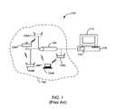
- FIG. 1is a simplified illustration of a conventional system for performing location estimation in wireless networks. This diagram is merely an example, which should not unduly limit the scope of the claims herein. One of ordinary skill in the art would recognize many variations, alternatives, and modifications.
- the selected geographic region 102can be any indoor and/or outdoor region within which it is desirable to locate a transmitting wireless station.
- the transmitting wireless stationcan be a wireless access point that is connected (e.g., 104 B) or unconnected (not shown) to the local area network 106 , a laptop (e.g., 104 A), a PDA, a mobile phone, and like.
- the transmitting wireless stationwhether an access point (connected or unconnected to the local area network 106 ) or a client such as a laptop, a PDA, a mobile phone, etc., is generically referred to herein as transmitting wireless station 104 .
- the selected geographic regioncan comprise one or more floors, buildings, or premises of an office, a commercial facility, a warehouse, an apartment, a hot-spot, and the like.
- the selected geographic regionalso comprises at least a portion of computer network 106 .
- the computer network 106can be any suitable network such as a local area network, a wide area network, or any combination of these.
- the computer networkis a local area network based on Ethernet technology.
- One or more RF sensor/signal detection devicesare spatially disposed within or in a selected vicinity of the selected geographic region 102 .
- the sniffers 108are provided at reference locations within or in the selected vicinity of the selected geographic region 102 .
- sniffer 108can listen to a radio channel and capture transmissions on that channel. In one embodiment, sniffer 108 can cycle through multiple radio channels on which wireless communication could take place. On each radio channel, sniffer 108 can wait and listen for any ongoing transmission. In one embodiment, sniffer 108 can operate on multiple radio channels simultaneously.
- sniffer 108can collect and record the relevant information about that transmission.
- the recorded informationincludes, but is not limited to, packet type, information derived from various fields in the packet, source identity, destination identity, and strength of the received signal associated with the transmission. Information such as the day or the time of the day when the transmission was detected may also be recorded.
- sniffer 108is coupled to the computer network 106 using its Ethernet network interface. In an alternative embodiment, the sniffer is coupled to the computer network 106 over a wireless connection.
- sniffer 108can be any suitable receiving device capable of detecting wireless activity.
- sniffer 108can have a processor, a flash memory, where the software code for sniffer functionality resides, a RAM, which serves as volatile memory during program execution, one or more 802.11a/b/g wireless network interface cards (NICs), which perform radio and wireless MAC layer functionality, one or more (i.e.
- One or more light emitting diodes (LEDs)can be provided on the sniffer device to convey visual indications such as, for example, device working properly, error condition, unauthorized wireless activity alert, and so on.
- sniffer 108can be built using a hardware platform similar to that used to build an AP, although having different functionality and software. In one embodiment, to more unobtrusively be incorporated in the selected geographic region, sniffer 108 could have a small form factor. In one embodiment, a sniffer 108 could also be provided with a radio transmit interface, thereby allowing sniffer 108 to generate interference with a suspected intruder's transmission or to transmit test signals.
- the snifferconveys the information derived from the detected wireless activity to processing system 110 , over one or more computer networks 106 .
- the processing systemcomprises software run on a PC, an appliance, or a server computer.
- the processing system 110may be physically located within the selected geographic region, in the vicinity of it, or at a remote location.
- the processing systemcan comprise codes 112 directed to perform various functions in accordance with the method of present invention and a display device 114 (e.g., a computer screen).
- the sniffers 108measure the strength of radio signals emanating from the wireless station and report their measurements to the processing system 110 .
- the radio signalsare associated with packets in the IEEE 802.11 format (also called 802.11 frames) that are transmitted from the station 104 .
- the packetsare transmitted from the station 104 to one or more other stations (such as wireless access points, wireless laptops, PDAs and so on) in the wireless network.
- the packets that are transmitted from the station 104are identified from other wireless packets by examining the source MAC address in the packets detected on the wireless medium. If the source MAC address in the packet is the MAC address of the wireless station 104 , the packet is considered to be transmitted by the station 104 .
- the processing system 110collects signal strength measurements associated with transmissions from station 104 from one or more of the sniffers 108 . Based on these measurements and the known reference locations of the one or more sniffers, the processing system 110 can compute (e.g., estimate) the physical location of the station 104 . For example, a triangulation method can be used to compute the physical location.
- the estimated physical locationcan be a point location, an area location within which the station is estimated to reside, or a volume location within which the station is estimated to reside.
- the estimated physical locationcan be displayed on the display device 114 , preferably in relation to the layout of the selected geographic region.
- This conventional techniquesuffers from several limitations which have been identified by the present applicants. For example, it is often desirable to locate wireless stations that are associated with undesirable wireless activity, such as security breaches or performance intrusions. Tracking the location of such devices can facilitate the system administrator in taking a variety of remedial actions.
- the conventional techniquesfail to provide location estimation of wireless stations associated with certain denial of service (DOS) attacks, certain identity theft attacks (e.g., MAC spoofing), certain address forging attacks, and the like.
- DOSdenial of service
- MAC spoofingidentity theft attacks
- address forging attacksand the like.
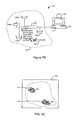
- FIG. 2Ais a simplified illustration of a wireless network under a denial of service attack.
- the wireless station 204 Ais associated with a certain wireless denial of service (DOS) attack on the network 206 .
- DOSwireless denial of service
- the DOS attackcan be an association flood attack, an authentication flood attack, an EAPOL start flood attack, and the like.
- the attackcan be launched on the authorized access point 204 B.
- the attacker station 204 Asends a number of connection requests (e.g., authentication requests, association requests, EAPOL start requests, etc.) to the access point 204 B to overwhelm the computing resources (e.g., memory, processing power, etc.) in the access point.
- the attacker device 204 Aoften sends these connection requests from random or varying source MAC addresses. This renders conventional techniques unusable to track the location of attacker device 204 A.
- 100 samples of received signal strengthe.g., signal strength measurements from 100 frames
- the device 204 Atransmits 1000 connection requests, each with a different source MAC address.
- the conventional techniquewill not be able to locate this device for want of 100 samples (e.g., frames) transmitted from the device 204 A from any one MAC address.
- FIG. 2Bis a simplified screen shot illustrating a display of estimated locations during a denial of service attack using a conventional system.
- the screen dimensionsare illustrated by square rectangle 250 .
- the real location 252 of the wireless station 204 Bis illustrated by a dot on the screen 250 .
- the estimated location of the DOS attacker 204 Ais not available and therefore, is not illustrated at any location on screen 250 .
- FIG. 2Cis a simplified illustration of a wireless network under an identity theft attack.
- the wireless station 204 Cis associated with a certain identity threat (e.g., MAC spoofing attack).
- the station 204 Cadvertises the same identity information (e.g., MAC address, SSID, and other characteristics) as that of the authorized access point 204 B in order to evade detection and engage is surreptitious hacking activities.
- identity informatione.g., MAC address, SSID, and other characteristics
- the received signal strengths measured by the sniffers from the frames transmitted by both the authorized access point 204 B and the spoofer device 204 Ccan average out (as all these frames appear to have been transmitted from the same MAC address, e.g., the MAC address of the access point 204 B). This results in inaccurate location estimation as illustrated below.
- the wireless station 204 Ccan further provide DOS attacks such as deauthentication attack, disassociation attack and the like.
- DOS attackssuch as deauthentication attack, disassociation attack and the like.
- the station 204 Cspoofs the identity (e.g., MAC address) of the authorized AP 204 B and transmits deauthentication messages on the wireless medium. This can disrupt connections of the legitimate clients connected to the AP 204 B.
- FIG. 2Dis a simplified screen shot illustrating a display of estimated locations during an identity theft attack using a conventional system.
- the screen dimensionsare illustrated by square rectangle 250 .
- the real location 252 of the wireless station 204 Bis illustrated by a dot on the screen 250 .
- the estimated location of the station 204 Cis illustrated on the screen by estimated location area 216 .
- the estimated location 216 of the DOS attacker 204 Adoes not include the real location 260 of the DOS attacker 204 A. Therefore, using conventional techniques, the system is not able to accurately display the estimated location of the attacker.
- Embodiments of the present inventionprovide location tracking systems and techniques that overcome these and other limitations we have observed in relation to conventional techniques. As described more fully below, embodiments of the present invention facilitate the location estimation of wireless stations associated with certain denial of service (DOS) attacks, certain identity theft attacks (e.g., MAC spoofing), certain address forging attacks, and the like.
- DOSdenial of service
- MAC spoofingidentity theft attacks
- address forging attackse.g., MAC spoofing
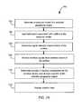
- FIG. 3is a simplified flowchart illustrating a method for estimating wireless station location according to an embodiment of the invention. This diagram is merely an example, which should not unduly limit the scope of the claims herein. One of ordinary skill in the art would recognize many variations, alternatives, and modifications.
- the methodcan be implemented using sniffers 108 and processing system 110 .
- One or more sniffers 108are spatially disposed ( 302 ) within and/or in the vicinity of a selected geographic region over which it is desirable to estimate the location of a wireless station.
- the wireless stationis associated with undesirable wireless activity, such as certain denial of service (DOS) attacks (e.g., association flood, authentication flood, EAPOL start flood, etc.), certain identity theft attacks (e.g., MAC spoofing, deauthentication attack, disassociation attack), certain address forging attacks, and the like.
- DOSdenial of service
- identity theft attackse.g., MAC spoofing, deauthentication attack, disassociation attack
- certain address forging attackse.g., MAC spoofing, deauthentication attack, disassociation attack
- the sniffersreceive wireless signals transmitted over wireless medium within at least a portion of the selected geographic region ( 304 ).
- the wireless signalsinclude wireless signals transmitted by the wireless station that is associated with the undesirable wireless activity.
- At least a subset of the received wireless signalsare processed ( 306 ) to identify a subset of the received wireless signals that are associated with the undesirable wireless activity.
- the received signal strength (e.g., received at one or more of the sniffers) associated with the wireless signals from the undesirable wireless activityis measured ( 308 ).
- the location of a transmitter of the wireless signals associated with the undesirable wireless activityis estimated ( 310 ) based on the received signal strength measurements associated with the wireless signals from the undesirable wireless activity. For example, a triangulation technique can be used for location estimation.
- a specific embodiment of the method illustrated in FIG. 3estimates the location of a wireless station associated with a certain DOS attack, such as an association flood attack, an authentication flood attack, an EAPOL start flood attack, and the like. For example, suppose that a wireless station is associated with an authentication flood attack. In this attack, the wireless station sends a flood of authentication requests to an AP from varying MAC addresses. Referring to step 306 in FIG. 3 , embodiments of the present invention identify wireless signals that are associated with authentication requests. As merely an example, 802.11 authentication request messages to the victim AP's MAC address are identified. The received signal strength of the identified authentication requests is measured by one or more of the sniffers. Based on the received signal strength measurements, the location of the wireless station associated with the attack is estimated.
- a certain DOS attacksuch as an association flood attack, an authentication flood attack, an EAPOL start flood attack, and the like.
- DOS attacksuch as an association flood attack, an authentication flood attack, an EAPOL start flood attack, and the like.
- FIG. 4Ais a simplified flowchart illustrating a method for estimating wireless station location during a denial of service attack according to an embodiment of the invention.
- This diagramis merely an example, which should not unduly limit the scope of the claims herein.
- wireless signalsare received ( 402 ) using sniffers.
- the wireless signalsare processed ( 404 ) to identify wireless signals associated with the DOS attack.
- the wireless signals associated with the DOS attackare identified using one or more signatures of the DOS attack.
- the DOS attackincludes an association flood attack.
- step 404can detect that the DOS attack is in progress.
- the detectioncan be based on the number of association requests to a victim access point from varying MAC addresses being more than a predetermined threshold.
- step 404can further identify wireless signals associated with the DOS attack by filtering out from the received 802.11 frames those frames which indicate association requests to the victim access point's MAC address.
- the DOS attackincludes a broadcast deauthentication attack.
- the broadcast deauthentication attackan attacker device sends broadcast deauthentication messages over the wireless medium by spoofing the MAC address of a victim AP. This can disrupt wireless connections between the victim AP and wireless clients connected to it.
- the detection of the deauthentication DOS attackis based on the number of broadcast deauthentication messages from the victim access point being more than a predetermined threshold.
- step 404can further identify wireless signals associated with the DOS attack by filtering those frames which indicate association requests to the victim access point's MAC address from the received 802.11 frames.
- the detection of the deauthentication DOS attackcan be based on detection of MAC spoofing of the victim access point.
- step 404can further identify wireless signals associated with the DOS attack by filtering out beacon or probe response frames that are transmitted by the attacker device from the received 802.11 frames.
- the beacon/probe response frames transmitted by the attacker device and beacon/probe response frames by the victim deviceinclude identical transmitter identity (e.g., MAC address) information.
- the DOS attackincludes a unicast deauthentication attack.
- an attacker devicecan send deauthentication messages over the wireless medium by spoofing the MAC address of a victim AP. The messages are addressed to the MAC address of a victim wireless client.
- the attacker devicecan send deauthentication messages over the wireless medium by spoofing the MAC address of the victim wireless client. The messages are addressed to the MAC address of the victim access point.
- the detectionis based on the number of unicast deauthentication messages from the victim access point to the victim wireless client or vice versa being more than a predetermined threshold and the detection of MAC spoofing of either or both of the victim access point and the victim wireless client.
- step 404can further identify wireless signals associated with the DOS attack by filtering those frames which indicate deauthentication messages from the victim access point's MAC address to the victim wireless client's MAC address or vice versa from the received 802.11 frames.
- the received signal strength associated with the wireless signals associated with the DOS attackis measured by one or more sniffers ( 406 ).
- the sniffersreport the received signal strength or information associated with the received signal strength to the processing unit 110 .
- location estimationis performed ( 408 ).
- the estimated location determined using the method described with respect to FIG. 4Acan be shown on a display device 214 as illustrated in FIG. 4B (e.g., in relation to the layout of the selected geographic region) as coordinates, a location area, a location volume, and the like ( 410 ).
- FIG. 4Bis a simplified illustration of a system for performing location estimation in wireless networks during a denial of service attack according to an embodiment of the present invention.
- DOS attacker 204 Alaunches a DOS attack (e.g., an association flood attack) on the network.
- the estimated location of the DOS attackeris indicated on display device 214 , which is used in conjunction with processing system 210 , which may be physically located within the selected geographic region 420 , in the vicinity of it, or at a remote location.
- the processing systemcomprises codes 212 directed to perform various functions in accordance with the method of present invention and a display device 214 (e.g., a computer screen).
- FIG. 4Cis a simplified screen shot illustrating the display of estimated locations during a denial of service attack according to an embodiment of the present invention.
- embodiments of the present inventionprovide for display of the estimated location of various wireless stations on display device 214 .
- the screen dimensionsare illustrated by square rectangle 250 .
- the real location 450 of wireless station 204 Bis illustrated in FIG. 4C .
- the estimated location of the DOS attacker 204 Ais indicated by location region 422 .
- the location region 422includes or is substantially close to the actual location 452 of the DOS attacker 204 A.
- the actual location 452is contained within the estimated location 422 .
- FIG. 5Ais a simplified flowchart illustrating a method for estimating wireless station location during an identity theft attack according to an embodiment of the invention. This diagram is merely an example, which should not unduly limit the scope of the claims herein. One of ordinary skill in the art would recognize many variations, alternatives, and modifications.
- one or more wireless stationsadvertise identity information (e.g., a MAC address) that is similar to that of an authorized AP (referred to as a “victim AP”) in order to evade detection and engage in surreptitious hacking activities.
- identity informatione.g., a MAC address
- a MAC addresse.g., the MAC address of the victim AP that is being spoofed by one or more wireless stations
- wireless signals transmitted from different devicese.g., the victim AP device and one or more spoofer devices
- the process of identifying wireless signals from a selected MAC addressincludes identifying the 802.11 style frames transmitted from the selected MAC address using the transmitter MAC address field in the frames.
- these framesconstitute frames transmitted from the victim AP as well as frames transmitted from the one or more spoofer devices.
- the frames transmitted from different devicesare identified ( 504 ) through analysis of one or more characteristics (e.g., values of certain fields in the frames, such as the TSF field and the sequence number field, received signal strength, etc.) associated with the frames.
- the frames transmitted from different devicesare identified ( 504 ) by capturing beacon frames or probe response frames transmitted from the selected MAC address (e.g., the MAC address as provided in the source address or the BSSID field in the beacon/probe response frame), and recording values contained in the TSF field of the captured beacon/probe response frames.
- the TSFis a 64-bit field in the IEEE 802.11 beacon/probe response frame that contains an AP's timestamp.
- the TSF counterstarts from zero every time the AP device is started, i.e., when the AP device is reset, restarted, rebooted, powered on, and like.
- the TSF valuehas units of microseconds and increments as a function of time.
- Embodiments of the present inventionutilize the TSF field by computing an approximation to the starting time (i.e. most recent starting time) of the AP device with a given MAC address from the TSF value contained in the captured beacon frame or probe response frame.
- the starting timecan be computed by subtracting the TSF value from the time the beacon packet from a given MAC address is captured. If there were a number of AP devices transmitting beacon packets with the given MAC address, it is unlikely that they were started at exactly the same time instant. Subsequently, different values for AP starting time approximation will be obtained and MAC spoofing can be detected.
- the frames (e.g., beacon and probe response) transmitted by the different devicescan be identified using the starting times computed from the TSF associated with them.
- F 1 , F 2 , F 3 , F 4 , and F 5are the beacon frames detected by the sniffer and that all have the same transmitter MAC address in them.
- the AP starting time approximation associated with the frames F 1 , F 2 , and F 4is t 1
- the AP starting time approximation associated with the frames F 3 and F 5is t 2 .
- t 1 and t 2are not equal to each other (e.g., considering certain margin for error).
- the frames F 1 , F 2 , and F 4can be inferred to be transmitted from one device (a first transmitter) and the frames F 3 and F 5 can be inferred to be transmitted from the other device (a second transmitter).
- At least two locationsare estimated ( 506 ), one based on the received signal strength associated with the wireless signals from the first transmitter device measured by one or more sniffers, and another based on the received signal strength associated with the wireless signals from the second transmitter device measured by one or more sniffers.
- one location estimationis done using the received signal strength associated with frames F 1 , F 2 , and F 4 measured by one or more sniffers.
- the other location estimationis performed using the received signal strength associated with frames F 3 and F 5 measured by one or more sniffers.
- FIG. 5Bis a simplified illustration of a system for performing location estimation in wireless networks during an identity theft attack according to an embodiment of the present invention.
- spoofer 204 Claunches an identity theft attack on the network.
- the estimated location of the spooferis indicated on display device 214 , which is used in conjunction with processing system 210 , which may be physically located within the selected geographic region 520 , in the vicinity of it, or at a remote location.
- the processing systemcomprises codes 212 directed to perform various functions in accordance with the method of present invention and a display device 214 (e.g., a computer screen).
- FIG. 5Cis a simplified screen shot illustrating the display of estimated locations during an identity theft attack according to an embodiment of the present invention.
- embodiments of the present inventionprovide for display of the estimated location of various wireless stations on display device 214 .
- the screen dimensionsare illustrated by square rectangle 250 .
- the real location 450 of wireless station 204 Bis illustrated in FIG. 5C .
- the estimated location of the spoofer 204 Cis indicated by location region 524 .
- the location region 524includes or is substantially close to the actual location 526 of the spoofer 204 C.
- the actual location 526is contained within the estimated location 524 .
- the estimated locationis shown as coordinates, location area, location volume, and the like.
- the location that is estimated to be farther from the actual known location of the victim APis indicated as the location of the spoofer.
- two estimated location regions 522 and 524are displayed.
- the location region 524is farther from the actual (known) location 450 of the authorized access point 204 B.
- the location region 524is indicated as the estimated location of the spoofer device 204 C.
- the location region 524includes or is substantially close to the actual location of the spoofer device 204 C.
- FIG. 6illustrates a method of identifying frames transmitted from a victim AP and frames transmitted from a spoofer device according to an embodiment of the present invention.
- the method 600provides a means of performing step 504 , in which wireless signals (e.g., frames) transmitted from a victim AP and wireless signals (e.g., frames) transmitted from a spoofer device are identified from among frames received from a selected MAC address.
- FIG. 6is merely an example of an embodiment of the present invention and should not unduly limit the scope of the claims herein.
- One of ordinary skill in the artwould recognize many variations, alternatives, and modifications.
- the method 600includes receiving an 802.11 frame including a selected source/transmitter MAC address and a TSF value ( 602 ).
- the frameincludes a beacon frame or a probe response frame.
- An approximation to the starting time of a wireless device associated with the selected source MAC addressis computed using the TSF value for the wireless device.
- the approximation to a starting time of a wireless deviceis computed by subtracting the TSF value from a time when the corresponding frame is received by the sniffer.
- the approximation to the starting timeis compared to one or more stored values ( 606 ). If a match between the approximated starting time and a stored value is found, (e.g., within a certain margin for error), the received signal strength associated with the frame is used for location estimation along with other frames (e.g., received in the past and/or future) for which the approximations to the starting time were also matched to the stored value ( 610 ). If a match is not found, a new stored value is created and appended to the one or more stored values ( 608 ). As further illustrated in FIG. 6 , in an embodiment, a separate location estimation process is performed using received signal strengths associated with each of the stored values (step 612 ).
- the process of identifying wireless signals represented by step 504uses other techniques to identify frames transmitted from different wireless devices. These techniques include the analysis of sequence numbers in the received frames, the analysis of received signal strengths associated with the received frames, and like. These alternative embodiments will be apparent to one of ordinary skill in the art.
- FIG. 7Aillustrates a method of performing triangulation for location estimation based on received signal strengths according to an embodiment of the present invention.
- the method 700is applicable to a variety of embodiments of the present invention, including steps 310 , 408 , and 508 as described previously.
- the illustration provided FIG. 7Ais merely an example, which should not unduly limit the scope of the claims herein.
- One of ordinary skill in the artwould recognize many variations, alternatives, and modifications.
- a computer modelis generated of a selected geographic region including a layout ( 702 ).
- the layoutis a spatial layout comprising layout components such as walls, rooms, columns, doors, partitions, furniture, foliage, patio, and the like.
- the computer modelincludes information associated with the layout components (e.g., physical dimensions, locations, material type, areas of human activity, etc.).
- Information associated with one or more components of a wireless networkis input into the computer model ( 704 ).
- the one or more componentsinclude at least one or more sniffer devices.
- the one or more componentsinclude one or more authorized access point devices in some embodiments.
- the informationincludes, but is not limited to, sniffer/access point locations, antenna types, antenna orientations, and the like.
- an exemplary embodiment to generate the computer model and input information associated with the wireless network componentsutilizes an image file representing a spatial layout of the selected geographic region.
- This image filecould include a *.gif, *.jpg, or other file format.
- the image filedepicts a floor plan or a map of the selected geographic region.
- the image fileis a photograph or a scanned version of the architectural drawing of the floor plan.
- the image filecan be displayed on a display device, such as 114 and 214 illustrated previously.
- the imagecan be annotated using a software library of drawing tools.
- drawing toolstypically allow a user to place objects, e.g., doors, windows, walls, entrances, obstacles, and other objects, in the floor plan.
- the drawing toolscould allow a user to drag and drop (e.g., with the help of computer mouse or other input device) various objects on the image displayed on the computer screen.
- the usercan also specify dimensions (e.g., thickness, length, width, height) of the objects.
- the usercan also specify the materials (e.g., brick wall, sheet rock, glass, metal, etc.) of which the various objects are made.
- the drawing toolsalso indicates unknown dimensions and/or unknown materials for objects in the layout (i.e., objects for which layout information is unavailable).
- the drawing toolsalso specify one or more regions in the defined geographic region that can be ignored while running computer simulations.
- the drawing toolsspecify regions of activity (e.g., movement of people).
- the computer modelis generated using an existing annotated layout image.
- a layout drawing file prepared by computer aided design (CAD) softwarecould be used.
- information associated with the sniffersis input to the computer model.
- This inputcan include the locations of the sniffers on the layout.
- a usercan input the locations to the computer model by providing x-y coordinates of the locations.
- a usercan, with the help of computer mouse, stylus, or other input device, point to a specific location on the computer display of the layout where a device/sniffer is (or will be) placed.
- the userwith the help of computer mouse, can drag and drop an icon corresponding to the device/sniffer on a computer display of the layout at a desired location.
- the input information associated with the sniffersmay also include information such as antenna type and orientation.
- the sniffer locations and characteristicsare programmatically generated and provided to the computer model.
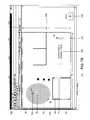
- FIG. 7Bis a simplified computer screen shot associated with the computer model of the geographic region according to an embodiment of the present invention.
- This diagramis merely an example, which should not unduly limit the scope of the claims herein.
- the screen shot illustrated in FIG. 7Bshows a selected geographic region screen for viewing and editing of a floor map.
- different material compositioncan be indicated by a different line pattern.
- walls 722are made of brick
- walls 724are made of concrete
- door 728is made of wood
- window 730is made of glass
- columns 732are made of sheet rock.
- a number of pull down menus 734 A- 734 Dare provided to assist a user in annotating the layout image.
- the snifferse.g., sniffers 736 A, 736 B, and 736 C
- the screen shotillustrates a sniffer location screen 738 A for positioning the set of sniffers on the floor map. For example, an indication (e.g., an icon) corresponding to a sniffer can be dragged from screen 738 A (e.g., using a computer mouse, arrow keys on keyboard, a stylus, and the like) and dropped at selected location on the layout.
- the screen shot in FIG. 7Balso illustrates sniffer information screen 738 B for inputting sniffer information regarding a set of sniffers. For example, the screen 738 B can be opened by clicking on the sniffer icon. The information (e.g., antenna type and orientation are illustrated) about the corresponding sniffer can then be entered into the screen.
- signal intensity characteristicsare determined over at least a portion of the selected geographic region using the computer model ( 706 ).
- a modelis generated for the signal strength received at the sniffer after transmission from a selected location within the selected geographic region.
- the received signal strength values for the modelare computed by using a ray tracing simulation method.
- An example of a ray tracing methodis described in the paper “A ray tracing approach to predicting indoor wireless transmission,” by Reinaldo Valenzuela of AT&T Bell Laboratories, published in the 43 rd IEEE Vehicular Technology Conference (1993).
- the strength (power) of a signal emanating from a transmitter at one location and received at another locationcan be computed. Note that through the reversibility characteristic of radio propagation, this value also corresponds to the signal intensity value when the transmitter and the receiver locations are interchanged.
- P — D 2 (dBm)P — K (dBm) ⁇ n* 10 log( D 2 /K ) ⁇ L 1 (dBm) ⁇ L 2 (dBm) ⁇ R 1 (dBm).
- the power D m at any of m points due to all possible signal componentsare computed and summed to generate the overall power prediction of the signal at a given point D. It should be appreciated that in some applications, the exact quantification of variables such as L 1 , L 2 , and R 2 is sometimes difficult, providing less accurate results than desired. Additionally, in other applications, the user does not know or not provided with adequate information regarding, for example, the dimensions or the material properties of layout objects, to the level of accuracy usually desired for radio level signal prediction.
- a probabilistic model(e.g., a Gaussian probability distribution) is used to account for these and other uncertainties.
- This probabilistic modelcan take into account inherent uncertainties associated with the radio characteristics (e.g., reflection loss, pass-through loss, and the like) of the layout objects, as well as uncertainties arising from inadequate specifications related to layout objects.
- each of these variablescan be modeled by using a Gaussian probability distribution.
- the mean and variance of the probability distribution associated with pass-through loss and reflection loss due to various types and sizes of objectscan be determined based on laboratory experimentation and stored in a database.
- the probabilistic modeltakes into account signal variations resulting from changes in the environment (e.g., the movement of people). For example, the signal path that passes through areas of high human activity (e.g., a cafeteria, corridors, conference rooms, etc.) exhibits a higher variability in signal strength.
- the probabilistic modeltakes into account signal variations resulting from changes in the state of obstacles. For example, a signal path that passes through a door area exhibits higher attenuation when the door is closed than when it is open or partially open. Other types of factors resulting in signal uncertainty or variations such as imprecise knowledge of antenna radiation patterns and/or orientation of transmitter devices can also be accounted for by assigning appropriate variance to signal loss due to these factors.
- the total signal power at the reception pointis then modeled by a Gaussian probability distribution having mean and variance equal to the sum of mean and variance respectively, of signal powers from all signal paths arriving from the transmission point at the reception point.
- At least a portion of the selected geographic region or the computer representation of the selected geographic regionis divided into number of cells.
- Each of the cellsmay be rectangular, circular, hexagonal, or any other appropriate shape.
- the cellsare as small in size as possible (e.g., 1 millimeter by 1 millimeter squares).
- cellstypically represent points rather than areas.
- Cellsare represented in the computer representation via their coordinates in either two dimensional (e.g., x-y coordinates) or three dimensional (e.g., x-y-z coordinates) space as applicable.
- the received signal strength modelis created to represent the received signal strength at each of the sniffer devices from the transmission of a given power level (e.g., 0 dBm) emanating from each of the cells.
- a given power levele.g., 0 dBm
- the signal modelpreferably represents the probability density function of the received signal strength.
- the probability density functionrepresents the probability of the received signal strength being within a given interval for a range of intervals.
- the probability density functionis a Gaussian density function with the predicted mean and predicted variance.
- alternative density functionssuch as the Rayleigh density function, the Log Normal density function, and others, can also be used.
- the transmission poweris p dBm
- the resultant predicted meancan be the mean computed for 0 dBm transmit power plus the transmission power p dBm.
- the wireless signals from a wireless devicesare received at the sniffers ( 708 ).
- the received signal strengthis measured.
- a functionis computed (e.g., average, moving average, exponential moving average, etc.) of the actual received signal strengths for one or more wireless signals at the sniffer.
- the received signal strengthis measured by a number of the sniffers.
- Step 710includes estimating the location of the wireless device.
- this stepincludes determining a number of probabilities associated with a number of locations in at least a portion of the selected geographic region.
- the number of probabilitiescan correspond to the probabilities of the wireless device being located at the number of locations.
- the probabilitiescan be computed utilizing at least information associated with the signal intensity characteristics and the received signal strength associated with the wireless signals from the wireless device that is measured by the sniffers.
- the location density (L(x,y))is computed.
- the location densityis defined as the probability of the received signal strength emanating from a transmission from the cell with coordinates (x,y) being within a small interval around each of the measured signal strength values at the one or more sniffers. This computation is based on the probability density function for the received signal strength previously calculated. Based on the principle of conditional probability, the probability of the wireless station being located at cell (x,y) is then proportional to L(x,y).
- the values of L(x,y) or other values that are proportional to L(x,y)are then represented on the display device in relation to the layout of the selected geographic region ( 712 ). In embodiments of the present invention, the values are displayed using a number of colors or gradations of one or more colors. Alternatively, the various ranges of these values may be displayed.
- additional processesare performed when the value of p cannot be determined from vendor information of the wireless transmitter, for example, due to the fact that the vendor's transmitter device allows for multiple possibilities of transmit powers.
- the principle of “hypothesis testing”is used.
- the values of L(x,y)are computed for all transmit power levels that are known to be transmitted by the wireless transmitter of interest.
- the values of L(x,y) at all cellsare summed for each of the power levels and the power level for which the sum is maximum is taken to be the estimate of transmit power.
- the values of L(x,y) for this most likely transmit powerare displayed.
- the value displayed at any cellis proportional to the sum total of L(x,y) at that cell over all possible transmit powers.
- the hypothesis testing principlecan also be applied to account for factors including, but not limited to, the antenna orientation of the wireless station.
- FIG. 7Cis another simplified computer screen shot of location probabilities displayed in relation to the layout of the geographic region according to an embodiment of the present invention.
- This diagramis merely an example, which should not unduly limit the scope of the claims herein.
- two regions 742 and 744are shown in FIG. 7C .
- Regions 742 and 744correspond to different probability ranges (e.g., greater than 0.8 and greater than 0.6, respectively).
- the usercan select the desired location likelihood level.
- the selected location likelihoodis larger, the cells for which the location density is larger are displayed.
- the usercan also specify the area of most likely locations that he or she desires to view.
- the various embodiments of the present inventionmay be implemented as part of a computer system.
- the computer systemmay include a computer, an input device, a display unit, and an interface. Additionally, the computer system may access the Internet. Furthermore, the computer may include a microprocessor. The microprocessor may be connected to a communication bus.
- the computermay also include a memory.
- the memorymay include Random Access Memory (RAM), Read Only Memory (ROM), and/or other memory types.
- the computer systemmay further include a storage device, which may be a hard disk drive or a removable storage drive such as a floppy disk drive, optical disk drive, and the like. The storage device can also be other similar means for loading computer programs or other instructions into the computer system.
- the term ‘computer’may include any processor-based or microprocessor-based system including systems using microcontrollers, digital signal processors (DSP), reduced instruction set circuits (RISC), application specific integrated circuits (ASICs), logic circuits, and any other circuit or processor capable of executing the functions described herein.
- DSPdigital signal processors
- RISCreduced instruction set circuits
- ASICsapplication specific integrated circuits
- the computer systemexecutes a set of instructions that are stored in one or more storage elements, in order to process input data.
- the storage elementsmay also hold data or other information as desired or needed.
- the storage elementmay be in the form of an information source or a physical memory element within the processing machine.
- the set of instructionsmay include various commands that instruct the processing machine to perform specific operations such as the processes of the various embodiments of the invention.
- the set of instructionsmay be in the form of a software program.
- the softwaremay be in various forms such as system software or application software. Further, the software may be in the form of a collection of separate programs, a program module within a larger program or a portion of a program module.
- the softwarealso may include modular programming in the form of object-oriented programming.
- the processing of input data by the processing machinemay be in response to user commands, or in response to results of previous processing, or in response to a request made by another processing machine.
- the terms ‘software’ and ‘firmware’are interchangeable, and include any computer program stored in memory for execution by a computer, including RAM memory, ROM memory, EPROM memory, EEPROM memory, and non-volatile RAM (NVRAM) memory.
- RAM memoryrandom access memory
- ROM memoryread-only memory
- EPROM memoryerasable programmable read-only memory
- EEPROM memoryelectrically erasable programmable read-only memory
- NVRAMnon-volatile RAM
Landscapes
- Engineering & Computer Science (AREA)
- Computer Networks & Wireless Communication (AREA)
- Signal Processing (AREA)
- Computer Security & Cryptography (AREA)
- Physics & Mathematics (AREA)
- General Physics & Mathematics (AREA)
- Radar, Positioning & Navigation (AREA)
- Remote Sensing (AREA)
- Computer Hardware Design (AREA)
- Computing Systems (AREA)
- General Engineering & Computer Science (AREA)
- Mobile Radio Communication Systems (AREA)
Abstract
Description
P—D0(dBm)=P—K(dBm)−n*10 log(D0/K),
where n is the exponent associated with radio wave propagation loss. For example, n=2 or n=1.7 for some applications.
P—D1(dBm)=P—K(dBm)−n*10 log(D1/K)−L1(dBm).
P—D2(dBm)=P—K(dBm)−n*10 log(D2/K)−L1(dBm)−L2(dBm)−R1(dBm).
Claims (24)
Priority Applications (1)
| Application Number | Priority Date | Filing Date | Title |
|---|---|---|---|
| US11/291,510US7856209B1 (en) | 2003-12-08 | 2005-11-30 | Method and system for location estimation in wireless networks |
Applications Claiming Priority (10)
| Application Number | Priority Date | Filing Date | Title |
|---|---|---|---|
| US52767303P | 2003-12-08 | 2003-12-08 | |
| US54363104P | 2004-02-11 | 2004-02-11 | |
| US56003404P | 2004-04-06 | 2004-04-06 | |
| US56902404P | 2004-05-07 | 2004-05-07 | |
| US60789704P | 2004-09-08 | 2004-09-08 | |
| US60781204P | 2004-09-08 | 2004-09-08 | |
| US61041704P | 2004-09-16 | 2004-09-16 | |
| US61041904P | 2004-09-16 | 2004-09-16 | |
| US10/966,353US7002943B2 (en) | 2003-12-08 | 2004-10-15 | Method and system for monitoring a selected region of an airspace associated with local area networks of computing devices |
| US11/291,510US7856209B1 (en) | 2003-12-08 | 2005-11-30 | Method and system for location estimation in wireless networks |
Related Parent Applications (1)
| Application Number | Title | Priority Date | Filing Date |
|---|---|---|---|
| US10/966,353Continuation-In-PartUS7002943B2 (en) | 2003-12-08 | 2004-10-15 | Method and system for monitoring a selected region of an airspace associated with local area networks of computing devices |
Publications (1)
| Publication Number | Publication Date |
|---|---|
| US7856209B1true US7856209B1 (en) | 2010-12-21 |
Family
ID=43333456
Family Applications (1)
| Application Number | Title | Priority Date | Filing Date |
|---|---|---|---|
| US11/291,510Active2027-06-30US7856209B1 (en) | 2003-12-08 | 2005-11-30 | Method and system for location estimation in wireless networks |
Country Status (1)
| Country | Link |
|---|---|
| US (1) | US7856209B1 (en) |
Cited By (36)
| Publication number | Priority date | Publication date | Assignee | Title |
|---|---|---|---|---|
| US20090156126A1 (en)* | 2006-04-03 | 2009-06-18 | Resonance Holdings Limited | Methods for determining proximity between radio frequency devices and controlling switches |
| US20110001603A1 (en)* | 2007-12-10 | 2011-01-06 | Nicholas Hedley Willis | Methods and apparatus relating to a security system |
| US20120289243A1 (en)* | 2011-05-11 | 2012-11-15 | Cambridge Silicon Radio Limited | Cooperative positioning |
| US20130083784A1 (en)* | 2011-09-29 | 2013-04-04 | Samsung Electronics Co., Ltd | Method and apparatus for providing service |
| US8462745B2 (en) | 2008-06-16 | 2013-06-11 | Skyhook Wireless, Inc. | Methods and systems for determining location using a cellular and WLAN positioning system by selecting the best WLAN PS solution |
| US8478297B2 (en) | 2004-10-29 | 2013-07-02 | Skyhook Wireless, Inc. | Continuous data optimization of moved access points in positioning systems |
| US8630664B2 (en) | 2004-10-29 | 2014-01-14 | Skyhook Wireless, Inc. | Access point database |
| US8638256B2 (en) | 2009-09-29 | 2014-01-28 | Skyhook Wireless, Inc. | Accuracy and performance of a hybrid positioning system |
| US20140087767A1 (en)* | 2012-09-21 | 2014-03-27 | Shin KUSAKARI | Communication terminal, communication method, and recording medium storing communication terminal control program |
| US8706083B2 (en) | 2009-01-07 | 2014-04-22 | Eckey Corporation | Bluetooth authentication system and method |
| US8789191B2 (en) | 2004-02-11 | 2014-07-22 | Airtight Networks, Inc. | Automated sniffer apparatus and method for monitoring computer systems for unauthorized access |
| US8890746B2 (en) | 2010-11-03 | 2014-11-18 | Skyhook Wireless, Inc. | Method of and system for increasing the reliability and accuracy of location estimation in a hybrid positioning system |
| US8983493B2 (en) | 2004-10-29 | 2015-03-17 | Skyhook Wireless, Inc. | Method and system for selecting and providing a relevant subset of Wi-Fi location information to a mobile client device so the client device may estimate its position with efficient utilization of resources |
| US9247443B2 (en) | 2013-07-25 | 2016-01-26 | Qualcomm Incorporated | Method and apparatus for use in detecting changes within wireless signal environment |
| US9338816B2 (en) | 2008-05-14 | 2016-05-10 | Aerohive Networks, Inc. | Predictive and nomadic roaming of wireless clients across different network subnets |
| US9413772B2 (en) | 2013-03-15 | 2016-08-09 | Aerohive Networks, Inc. | Managing rogue devices through a network backhaul |
| US9565125B2 (en) | 2012-06-14 | 2017-02-07 | Aerohive Networks, Inc. | Multicast to unicast conversion technique |
| US9572135B2 (en) | 2009-01-21 | 2017-02-14 | Aerohive Networks, Inc. | Airtime-based packet scheduling for wireless networks |
| US20170131125A1 (en)* | 2010-12-13 | 2017-05-11 | Xandem Technology, Llc | Systems and methods of device-free motion detection and presence detection |
| US9674892B1 (en) | 2008-11-04 | 2017-06-06 | Aerohive Networks, Inc. | Exclusive preshared key authentication |
| US9814055B2 (en) | 2010-09-07 | 2017-11-07 | Aerohive Networks, Inc. | Distributed channel selection for wireless networks |
| US9848174B2 (en)* | 2008-12-30 | 2017-12-19 | May Patents Ltd. | Electric shaver with imaging capability |
| US9900251B1 (en) | 2009-07-10 | 2018-02-20 | Aerohive Networks, Inc. | Bandwidth sentinel |
| US10091065B1 (en) | 2011-10-31 | 2018-10-02 | Aerohive Networks, Inc. | Zero configuration networking on a subnetted network |
| US10097560B1 (en) | 2016-03-08 | 2018-10-09 | Symantec Corporation | Systems and methods for automatically adjusting user access permissions based on beacon proximity |
| US10178122B1 (en)* | 2016-08-12 | 2019-01-08 | Symantec Corporation | Systems and methods for disseminating location-based reputations for link-layer wireless attacks |
| US10389650B2 (en) | 2013-03-15 | 2019-08-20 | Aerohive Networks, Inc. | Building and maintaining a network |
| US20200106684A1 (en)* | 2018-09-27 | 2020-04-02 | Intel Corporation | Apparatus, system and method of a wireless communication multi-stream sniffer |
| US10771498B1 (en)* | 2015-06-10 | 2020-09-08 | Marvell Asia Pte., Ltd. | Validating de-authentication requests |
| US10798634B2 (en) | 2007-04-27 | 2020-10-06 | Extreme Networks, Inc. | Routing method and system for a wireless network |
| CN112752288A (en)* | 2019-10-31 | 2021-05-04 | 罗德施瓦兹两合股份有限公司 | Monitoring cellular wireless networks for spectrum anomalies and training spectrum anomaly neural networks |
| CN113207131A (en)* | 2020-01-31 | 2021-08-03 | 瞻博网络公司 | Multiple wireless device location determination |
| US11115857B2 (en) | 2009-07-10 | 2021-09-07 | Extreme Networks, Inc. | Bandwidth sentinel |
| US11212681B1 (en)* | 2020-06-29 | 2021-12-28 | Fortinet, Inc. | Intrusion detection in a wireless network using location information of wireless devices |
| US12317083B2 (en) | 2023-02-22 | 2025-05-27 | Arista Networks, Inc. | Wireless intrusion prevention using channel switch announcement |
| US12375921B2 (en) | 2022-06-08 | 2025-07-29 | Arista Networks, Inc. | Wireless intrusion prevention |
Citations (65)
| Publication number | Priority date | Publication date | Assignee | Title |
|---|---|---|---|---|
| US4914546A (en) | 1989-02-03 | 1990-04-03 | Micrel Incorporated | Stacked multi-polysilicon layer capacitor |
| US5187637A (en) | 1992-02-14 | 1993-02-16 | At&T Bell Laboratories | Monolithic high-voltage capacitor |
| US5301150A (en) | 1992-06-22 | 1994-04-05 | Intel Corporation | Flash erasable single poly EPROM device |
| US5354701A (en) | 1991-04-18 | 1994-10-11 | Industrial Technology Research Institute | Doubled stacked trench capacitor DRAM and method of fabricating |
| US5587869A (en) | 1994-02-17 | 1996-12-24 | Murata Manufacturing Co., Ltd. | High-voltage capacitor manufacturing method and high-voltage capacitor |
| US5831692A (en) | 1996-08-21 | 1998-11-03 | Samsung Electronics Co., Ltd. | Stacked capacitor structures for liquid crystal displays and related methods |
| US5908443A (en) | 1996-04-12 | 1999-06-01 | Survivalink Corporation | Stacked capacitor truncated damped sinusoidal defibrillation waveform |
| US5926064A (en) | 1998-01-23 | 1999-07-20 | National Semiconductor Corporation | Floating MOS capacitor |
| US5987306A (en)* | 1994-06-01 | 1999-11-16 | Telefonaktiebolaget L M Ericsson | System for monitoring telephone networks and/or data communication networks, especially mobile telephone networks |
| US6137153A (en) | 1998-02-13 | 2000-10-24 | Advanced Micro Devices, Inc. | Floating gate capacitor for use in voltage regulators |
| US6242989B1 (en) | 1998-09-12 | 2001-06-05 | Agere Systems Guardian Corp. | Article comprising a multi-port variable capacitor |
| US6262469B1 (en) | 1998-03-25 | 2001-07-17 | Advanced Micro Devices, Inc. | Capacitor for use in a capacitor divider that has a floating gate transistor as a corresponding capacitor |
| US6269246B1 (en) | 1998-09-22 | 2001-07-31 | Ppm, Inc. | Location determination using RF fingerprinting |
| WO2001093531A2 (en) | 2000-05-31 | 2001-12-06 | Invicta Networks, Inc. | Systems and methods for distributed network protection |
| US20010052014A1 (en) | 2000-05-31 | 2001-12-13 | Sheymov Victor I. | Systems and methods for distributed network protection |
| US6353406B1 (en) | 1996-10-17 | 2002-03-05 | R.F. Technologies, Inc. | Dual mode tracking system |
| US6389294B1 (en) | 1997-04-11 | 2002-05-14 | Nokia Telecommunications Oy | Method of determining effect of radio wave multipath fading |
| US6393294B1 (en) | 1998-09-22 | 2002-05-21 | Polaris Wireless, Inc. | Location determination using RF fingerprinting |
| US6414634B1 (en) | 1997-12-04 | 2002-07-02 | Lucent Technologies Inc. | Detecting the geographical location of wireless units |
| US6429812B1 (en)* | 1998-01-27 | 2002-08-06 | Steven M. Hoffberg | Mobile communication device |
| US6563691B2 (en) | 2000-09-18 | 2003-05-13 | Kabushiki Kaisha Toshiba | Mounting structure for capacitors |
| US20030135762A1 (en) | 2002-01-09 | 2003-07-17 | Peel Wireless, Inc. | Wireless networks security system |
| US20030137453A1 (en) | 2001-06-29 | 2003-07-24 | Hannah Eric C. | Determining wireless device locations |
| US20030186679A1 (en) | 2002-03-27 | 2003-10-02 | International Business Machines Corporation | Methods, apparatus and program product for monitoring network security |
| US20030185244A1 (en) | 2002-03-29 | 2003-10-02 | Miles Wu | Detecting a counterfeit access point in a wireless local area network |
| US6646499B2 (en) | 2000-05-05 | 2003-11-11 | Infineon Technologies Ag | Voltage-controlled capacitor |
| US20030217283A1 (en) | 2002-05-20 | 2003-11-20 | Scott Hrastar | Method and system for encrypted network management and intrusion detection |
| US20030217289A1 (en) | 2002-05-17 | 2003-11-20 | Ken Ammon | Method and system for wireless intrusion detection |
| US20030218570A1 (en) | 2002-05-02 | 2003-11-27 | Microsoft | Method and system for determining the location of a mobile computer |
| US20030221006A1 (en) | 2002-04-04 | 2003-11-27 | Chia-Chee Kuan | Detecting an unauthorized station in a wireless local area network |
| US20030219008A1 (en) | 2002-05-20 | 2003-11-27 | Scott Hrastar | System and method for wireless lan dynamic channel change with honeypot trap |
| GB2389483A (en) | 2002-04-11 | 2003-12-10 | Apoapsis Ltd | Wireless monitoring for performance and security of network |
| US6664609B2 (en) | 2001-03-26 | 2003-12-16 | Matsushita Electric Industrial Co., Ltd. | High frequency differential amplification circuit with reduced parasitic capacitance |
| US20030232598A1 (en) | 2002-06-13 | 2003-12-18 | Daniel Aljadeff | Method and apparatus for intrusion management in a wireless network using physical location determination |
| US20030233567A1 (en) | 2002-05-20 | 2003-12-18 | Lynn Michael T. | Method and system for actively defending a wireless LAN against attacks |
| US20030236990A1 (en) | 2002-05-20 | 2003-12-25 | Scott Hrastar | Systems and methods for network security |
| US20040003285A1 (en) | 2002-06-28 | 2004-01-01 | Robert Whelan | System and method for detecting unauthorized wireless access points |
| US6674403B2 (en) | 2001-09-05 | 2004-01-06 | Newbury Networks, Inc. | Position detection and location tracking in a wireless network |
| US20040008652A1 (en)* | 2002-05-20 | 2004-01-15 | Tanzella Fred C. | System and method for sensing wireless LAN activity |
| US20040023640A1 (en) | 2002-08-02 | 2004-02-05 | Ballai Philip N. | System and method for detection of a rogue wireless access point in a wireless communication network |
| US20040028000A1 (en) | 2002-08-12 | 2004-02-12 | Harris Corporation | Mobile ad-hoc network with intrusion detection features and related methods |
| US20040028017A1 (en) | 2002-07-29 | 2004-02-12 | Whitehill Eric A. | System and method for determining physical location of a node in a wireless network during an authentication check of the node |
| WO2004019559A2 (en) | 2002-08-20 | 2004-03-04 | Bluesoft Ltd. | Method and system for location finding in a wireless local area network |
| WO2004028121A2 (en) | 2002-09-23 | 2004-04-01 | Wimetrics Corporation | System and method for wireless local area network monitoring and intrusion detection |
| US20040072577A1 (en) | 2000-12-29 | 2004-04-15 | Ekahau Oy | Location estimation in wireless telecommunication networks |
| US20040078151A1 (en) | 2002-10-18 | 2004-04-22 | Daniel Aljadeff | Wireless local area network (WLAN) channel radio-frequency identification (RFID) tag system and method therefor |
| US20040098610A1 (en) | 2002-06-03 | 2004-05-20 | Hrastar Scott E. | Systems and methods for automated network policy exception detection and correction |
| US6754488B1 (en) | 2002-03-01 | 2004-06-22 | Networks Associates Technologies, Inc. | System and method for detecting and locating access points in a wireless network |
| US20040137915A1 (en) | 2002-11-27 | 2004-07-15 | Diener Neil R. | Server and multiple sensor system for monitoring activity in a shared radio frequency band |
| WO2004059912A1 (en) | 2002-12-31 | 2004-07-15 | International Business Machines Corporation | Spatial boundary admission control for wireless networks |
| US20040152470A1 (en) | 2003-02-04 | 2004-08-05 | Spain David Stevenson | Location estimation of wireless terminals though pattern matching of signal-strength differentials |
| US20040157624A1 (en) | 2002-05-20 | 2004-08-12 | Hrastar Scott E. | Systems and methods for adaptive location tracking |
| US6799047B1 (en) | 1999-02-25 | 2004-09-28 | Microsoft Corporation | Locating and tracking a user in a wireless network through environmentally profiled data |
| US20040203764A1 (en) | 2002-06-03 | 2004-10-14 | Scott Hrastar | Methods and systems for identifying nodes and mapping their locations |
| US20040206999A1 (en) | 2002-05-09 | 2004-10-21 | Impinj, Inc., A Delaware Corporation | Metal dielectric semiconductor floating gate variable capacitor |
| WO2004095192A2 (en) | 2003-04-21 | 2004-11-04 | Airdefense, Inc. | Systems and methods for securing wireless computer networks |
| US20040252837A1 (en) | 2003-04-03 | 2004-12-16 | Elaine Harvey | Method and system for detecting characteristics of a wireless network |
| US6839560B1 (en) | 1999-02-25 | 2005-01-04 | Microsoft Corporation | Using a derived table of signal strength data to locate and track a user in a wireless network |
| US20050039047A1 (en) | 2003-07-24 | 2005-02-17 | Amit Raikar | Method for configuring a network intrusion detection system |
| US6897776B1 (en) | 2002-02-06 | 2005-05-24 | Intermec Ip Corp. | Electronic countermeasure (ECM) system and method |
| US6990428B1 (en) | 2003-07-28 | 2006-01-24 | Cisco Technology, Inc. | Radiolocation using path loss data |
| US7110756B2 (en) | 2003-10-03 | 2006-09-19 | Cognio, Inc. | Automated real-time site survey in a shared frequency band environment |
| US7286515B2 (en) | 2003-07-28 | 2007-10-23 | Cisco Technology, Inc. | Method, apparatus, and software product for detecting rogue access points in a wireless network |
| US7302269B1 (en) | 2004-03-18 | 2007-11-27 | Cisco Technology, Inc. | Radiolocation in a wireless network using time difference of arrival |
| US7307980B1 (en) | 1999-07-02 | 2007-12-11 | Cisco Technology, Inc. | Change of codec during an active call |
- 2005
- 2005-11-30USUS11/291,510patent/US7856209B1/enactiveActive
Patent Citations (68)
| Publication number | Priority date | Publication date | Assignee | Title |
|---|---|---|---|---|
| US4914546A (en) | 1989-02-03 | 1990-04-03 | Micrel Incorporated | Stacked multi-polysilicon layer capacitor |
| US5354701A (en) | 1991-04-18 | 1994-10-11 | Industrial Technology Research Institute | Doubled stacked trench capacitor DRAM and method of fabricating |
| US5187637A (en) | 1992-02-14 | 1993-02-16 | At&T Bell Laboratories | Monolithic high-voltage capacitor |
| US5301150A (en) | 1992-06-22 | 1994-04-05 | Intel Corporation | Flash erasable single poly EPROM device |
| US5587869A (en) | 1994-02-17 | 1996-12-24 | Murata Manufacturing Co., Ltd. | High-voltage capacitor manufacturing method and high-voltage capacitor |
| US5987306A (en)* | 1994-06-01 | 1999-11-16 | Telefonaktiebolaget L M Ericsson | System for monitoring telephone networks and/or data communication networks, especially mobile telephone networks |
| US5908443A (en) | 1996-04-12 | 1999-06-01 | Survivalink Corporation | Stacked capacitor truncated damped sinusoidal defibrillation waveform |
| US5831692A (en) | 1996-08-21 | 1998-11-03 | Samsung Electronics Co., Ltd. | Stacked capacitor structures for liquid crystal displays and related methods |
| US6353406B1 (en) | 1996-10-17 | 2002-03-05 | R.F. Technologies, Inc. | Dual mode tracking system |
| US6389294B1 (en) | 1997-04-11 | 2002-05-14 | Nokia Telecommunications Oy | Method of determining effect of radio wave multipath fading |
| US6414634B1 (en) | 1997-12-04 | 2002-07-02 | Lucent Technologies Inc. | Detecting the geographical location of wireless units |
| US5926064A (en) | 1998-01-23 | 1999-07-20 | National Semiconductor Corporation | Floating MOS capacitor |
| US6429812B1 (en)* | 1998-01-27 | 2002-08-06 | Steven M. Hoffberg | Mobile communication device |
| US6137153A (en) | 1998-02-13 | 2000-10-24 | Advanced Micro Devices, Inc. | Floating gate capacitor for use in voltage regulators |
| US6262469B1 (en) | 1998-03-25 | 2001-07-17 | Advanced Micro Devices, Inc. | Capacitor for use in a capacitor divider that has a floating gate transistor as a corresponding capacitor |
| US6242989B1 (en) | 1998-09-12 | 2001-06-05 | Agere Systems Guardian Corp. | Article comprising a multi-port variable capacitor |
| US6782265B2 (en) | 1998-09-22 | 2004-08-24 | Polaris Wireless, Inc. | Location determination using RF fingerprinting |
| US6393294B1 (en) | 1998-09-22 | 2002-05-21 | Polaris Wireless, Inc. | Location determination using RF fingerprinting |
| US6269246B1 (en) | 1998-09-22 | 2001-07-31 | Ppm, Inc. | Location determination using RF fingerprinting |
| US6799047B1 (en) | 1999-02-25 | 2004-09-28 | Microsoft Corporation | Locating and tracking a user in a wireless network through environmentally profiled data |
| US6839560B1 (en) | 1999-02-25 | 2005-01-04 | Microsoft Corporation | Using a derived table of signal strength data to locate and track a user in a wireless network |
| US7307980B1 (en) | 1999-07-02 | 2007-12-11 | Cisco Technology, Inc. | Change of codec during an active call |
| US6646499B2 (en) | 2000-05-05 | 2003-11-11 | Infineon Technologies Ag | Voltage-controlled capacitor |
| US20010052014A1 (en) | 2000-05-31 | 2001-12-13 | Sheymov Victor I. | Systems and methods for distributed network protection |
| WO2001093531A2 (en) | 2000-05-31 | 2001-12-06 | Invicta Networks, Inc. | Systems and methods for distributed network protection |
| US6563691B2 (en) | 2000-09-18 | 2003-05-13 | Kabushiki Kaisha Toshiba | Mounting structure for capacitors |
| US20040072577A1 (en) | 2000-12-29 | 2004-04-15 | Ekahau Oy | Location estimation in wireless telecommunication networks |
| US6664609B2 (en) | 2001-03-26 | 2003-12-16 | Matsushita Electric Industrial Co., Ltd. | High frequency differential amplification circuit with reduced parasitic capacitance |
| US20030137453A1 (en) | 2001-06-29 | 2003-07-24 | Hannah Eric C. | Determining wireless device locations |
| US6674403B2 (en) | 2001-09-05 | 2004-01-06 | Newbury Networks, Inc. | Position detection and location tracking in a wireless network |
| US20030135762A1 (en) | 2002-01-09 | 2003-07-17 | Peel Wireless, Inc. | Wireless networks security system |
| US6897776B1 (en) | 2002-02-06 | 2005-05-24 | Intermec Ip Corp. | Electronic countermeasure (ECM) system and method |
| US6754488B1 (en) | 2002-03-01 | 2004-06-22 | Networks Associates Technologies, Inc. | System and method for detecting and locating access points in a wireless network |
| US20030186679A1 (en) | 2002-03-27 | 2003-10-02 | International Business Machines Corporation | Methods, apparatus and program product for monitoring network security |
| US20030185244A1 (en) | 2002-03-29 | 2003-10-02 | Miles Wu | Detecting a counterfeit access point in a wireless local area network |
| US20030221006A1 (en) | 2002-04-04 | 2003-11-27 | Chia-Chee Kuan | Detecting an unauthorized station in a wireless local area network |
| GB2389483A (en) | 2002-04-11 | 2003-12-10 | Apoapsis Ltd | Wireless monitoring for performance and security of network |
| US20030218570A1 (en) | 2002-05-02 | 2003-11-27 | Microsoft | Method and system for determining the location of a mobile computer |
| US6664925B1 (en) | 2002-05-02 | 2003-12-16 | Microsoft Corporation | Method and system for determining the location of a mobile computer |
| US20040206999A1 (en) | 2002-05-09 | 2004-10-21 | Impinj, Inc., A Delaware Corporation | Metal dielectric semiconductor floating gate variable capacitor |
| US20030217289A1 (en) | 2002-05-17 | 2003-11-20 | Ken Ammon | Method and system for wireless intrusion detection |
| US20030233567A1 (en) | 2002-05-20 | 2003-12-18 | Lynn Michael T. | Method and system for actively defending a wireless LAN against attacks |
| US20040008652A1 (en)* | 2002-05-20 | 2004-01-15 | Tanzella Fred C. | System and method for sensing wireless LAN activity |
| US20030217283A1 (en) | 2002-05-20 | 2003-11-20 | Scott Hrastar | Method and system for encrypted network management and intrusion detection |
| US7086089B2 (en) | 2002-05-20 | 2006-08-01 | Airdefense, Inc. | Systems and methods for network security |
| US20030219008A1 (en) | 2002-05-20 | 2003-11-27 | Scott Hrastar | System and method for wireless lan dynamic channel change with honeypot trap |
| US20030236990A1 (en) | 2002-05-20 | 2003-12-25 | Scott Hrastar | Systems and methods for network security |
| US20040157624A1 (en) | 2002-05-20 | 2004-08-12 | Hrastar Scott E. | Systems and methods for adaptive location tracking |
| US20040098610A1 (en) | 2002-06-03 | 2004-05-20 | Hrastar Scott E. | Systems and methods for automated network policy exception detection and correction |
| US20040203764A1 (en) | 2002-06-03 | 2004-10-14 | Scott Hrastar | Methods and systems for identifying nodes and mapping their locations |
| US20030232598A1 (en) | 2002-06-13 | 2003-12-18 | Daniel Aljadeff | Method and apparatus for intrusion management in a wireless network using physical location determination |
| US20040003285A1 (en) | 2002-06-28 | 2004-01-01 | Robert Whelan | System and method for detecting unauthorized wireless access points |
| US20040028017A1 (en) | 2002-07-29 | 2004-02-12 | Whitehill Eric A. | System and method for determining physical location of a node in a wireless network during an authentication check of the node |
| US20040023640A1 (en) | 2002-08-02 | 2004-02-05 | Ballai Philip N. | System and method for detection of a rogue wireless access point in a wireless communication network |
| US20040028000A1 (en) | 2002-08-12 | 2004-02-12 | Harris Corporation | Mobile ad-hoc network with intrusion detection features and related methods |
| WO2004019559A2 (en) | 2002-08-20 | 2004-03-04 | Bluesoft Ltd. | Method and system for location finding in a wireless local area network |
| WO2004028121A2 (en) | 2002-09-23 | 2004-04-01 | Wimetrics Corporation | System and method for wireless local area network monitoring and intrusion detection |
| US20040078151A1 (en) | 2002-10-18 | 2004-04-22 | Daniel Aljadeff | Wireless local area network (WLAN) channel radio-frequency identification (RFID) tag system and method therefor |
| US20040137915A1 (en) | 2002-11-27 | 2004-07-15 | Diener Neil R. | Server and multiple sensor system for monitoring activity in a shared radio frequency band |
| WO2004059912A1 (en) | 2002-12-31 | 2004-07-15 | International Business Machines Corporation | Spatial boundary admission control for wireless networks |
| US20040152470A1 (en) | 2003-02-04 | 2004-08-05 | Spain David Stevenson | Location estimation of wireless terminals though pattern matching of signal-strength differentials |
| US20040252837A1 (en) | 2003-04-03 | 2004-12-16 | Elaine Harvey | Method and system for detecting characteristics of a wireless network |
| WO2004095192A2 (en) | 2003-04-21 | 2004-11-04 | Airdefense, Inc. | Systems and methods for securing wireless computer networks |
| US20050039047A1 (en) | 2003-07-24 | 2005-02-17 | Amit Raikar | Method for configuring a network intrusion detection system |
| US6990428B1 (en) | 2003-07-28 | 2006-01-24 | Cisco Technology, Inc. | Radiolocation using path loss data |
| US7286515B2 (en) | 2003-07-28 | 2007-10-23 | Cisco Technology, Inc. | Method, apparatus, and software product for detecting rogue access points in a wireless network |
| US7110756B2 (en) | 2003-10-03 | 2006-09-19 | Cognio, Inc. | Automated real-time site survey in a shared frequency band environment |
| US7302269B1 (en) | 2004-03-18 | 2007-11-27 | Cisco Technology, Inc. | Radiolocation in a wireless network using time difference of arrival |
Non-Patent Citations (40)
| Title |
|---|
| Air Defense Inc., [Brochure], Enterprise Wireless LAN Security, 4 pages. |
| Air Defense Inc., [Data Sheet], AirDefense 4.0, 2 pages. |
| Air Defense Inc., [Data Sheet], AirDefense Data Sheet, 2 pages. |
| Air Defense Inc., [Data Sheet], Enterprise Wireless LAN Security, 2 pages. |
| Air Defense Inc., [User Guide] AirDefense Guard, Issue 1.02, Release 3.0, 295 pages. |
| Air Defense Inc., [User Guide] AirDefense Guard, Issue 2.2, Release 3.0, 317 pages |
| Air Defense Inc., [User Guide] AirDefense Version 2.0, Integrated WLAN Security Appliance, 131 pages. |
| Air Defense Inc., [User Guide] Integrated WLAN Security Solutions, Release 2.1, 164 pages. |
| Air Defense Inc., [User Guide] Wireless LAN Monitoring Solutions, Release 3.5, 374 pages. |
| Air Defense Inc., [User Guide], AirDefense Mobile: Integrated WLAN Security Appliance 94 pages. |
| Air Defense Inc., [White Paper], Wireless LANs: Risks and Defenses, 7 pages. |
| Air Defense Inc., AirDefense Guard 3.5, 2 pages. |
| Air Defense Inc., Integrated WLAN Security Solutions, Quick Start Release 3.0, 16 pages. |
| Air Defense Inc., Release Notes r4.0, 18 pages. |
| Air Defense Inc., Wireless LAN Monitoring Solutions, Issue 1.1, Quick Start Release 3.5, 42 pages. |
| Bahl et al., "RADAR: An In-Building RF-based User Location and Tracking System", IEEE Infocom 2000, vol. 2, pp. 775-784, (Mar. 2000). |
| Bellardo et al., "Denial-of-Service Attacks: Real Vulnerabilities and Practical Solutions, Department of Computer and Science Engineering," University of California at San Diego, Proceedings of the USENIX Security Symposium, Washington, DC, 18 pages, (Aug. 2003. |
| Bellovin: "A Technique for Counting NATed Hosts", AT&T Labs Research, IMW02, Nov. 6-8, 2002, Marseille, France, pp. 267-272. |
| Brian Moran: The hacker's wireless toolbox: part 2, COMPUTERWORLD, alleged Jul. 17, 2003, http://www.computerworld.com/mobiletopics/mobile/story/0,10801,83152,00.html. |
| Castro et al., "A Probabilistic Location Service for Wireless Network Environments", UbiquitoComputing 2001, 18 pages, (Sep. 2001). |
| Chirumamilla et al., "Agent Based Intrusion Detection and Response System for Wirless LANs," Dept. of Comput. Sci. & Eng., Nebraska Univ., Lincoln, NE, USA This paper appears in: Communications, 2003. ICC '03. IEEE International Conference, vol. 1, pp. 492-496 (May 11-15, 2003). |
| Clouqueur et al., "Sensor Deployment Strategy for Detection of Targets Traversing a Region,"Mobile Networks and Applications vol. 8, No. 4, pp. 453-461 (Apr. 2003). |
| Ganu et al., "Infrastructure-based location estimation in WLAN Networks," IEEE Wireless Communications and Networking Conference (WCNC 2004), 6 pages. |
| Guo et al.: "Sequence Number-Based MAC Address Spoof Detection," in Proceedings of 8th International Symposium on Recent Advances in Intrusion Detection (RAID 2005), Sep. 2005, 20 pgs. |
| Hatami et al., "In-building Intruder Detection for WLAN Access," IEEE Position Location and Navigation Symposium, 2004. PLANS 2004, pp. 592-597. (Apr. 26-29, 2004). |
| IBM extends its Wireless Security Auditor with more automatic features, Serverworld, Jun. 2002 (accessed Apr. 10, 2003). |
| IBM Research, Distributed Wireless Security Auditor, http://www.research.ibm.com/gsal/dwsa/, accessed Oct. 25, 2007. |
| IBM Research, Wireless Security Auditor (WSA), http://www.research.ibm.com/gsal/wsa/, accessed Oct. 25, 2007. |
| Korba, "Security System for Wireless Local Area Networks," Personal, Indoor and Mobile Radio Communications, 1998. The Ninth IEEE International Symposium, Boston, MA USA, vol. 3, pp. 1550-1554 (Sep. 8, 1998-Sep. 11, 1998). |
| Lim et al., "Wireless Intrusion Detection and Response," IEEE., Proceedings of the 2003 IEEE Workshop on Information Assurance United States Military Academy, West Point, NY (Jun. 2003). |
| PR: IBM Debuts First Self-Diagnostic Wireless Security Tool on Linux, http://www.linuxtoday.com/infrastructure/2002061700826NWNT, alleged publication date: Jun 17, 2002, accessed Oct. 25, 2007. |
| Roos et al., "A Probabilistic Approach to WLAN User Location Estimation", International Journal of Wireless Information Networks, vol. 9, No. 3, pp. 155-164(Jul. 2002). |
| Roos et al., "A Statistical Modeling Approach to Location Estimation," IEEE Transactions on Mobile Computing, vol. 1, No. 1, pp. 59-69 (Jan.-Mar. 2002). |
| Saha et al., "Location Determination of a Mobile Device using IEEE 802.11 Access Point Signals," IEEE Wireless Communication and Networking Conference (WCNC), (Mar. 2003). |
| Source code of a wireless monitoring tool available on the Internet, http://svn.kismetwireless.net/code/tags/kismet-2004-10-R1/CHANGELOG, Jun. 9, 2004, 2 pgs. |
| Valenzuela, "A Ray Tracing Approach to Predicting Indoor Wireless Transmission," 43rd IEEE Vehicular Technology Conference, pp. 214-218 (2003). |
| Wright "Detecting Wireless LAN MAC Address Spoofing", Jan. 21, 2003. |
| Yeo et al.: "A Framework for Wireless LAN Monitoring and its Applications," Department of Computer Science, University of Maryland, College Park, MD 20742; Proceedings of the 2004 ACM workshop on wireless security; Publication date: Oct. 1, 2004; pp. 70-79. |
| Youssef et al., "WLAN Location Determination via Clustering and Probability Distributions", IEEE PerCom 2003, 8 pages, (Mar. 2003). |
| Zhang et al., "Intrusion Detection Techniques for Mobile Wireless Networks," Wireless Networks vol. 9, No. 5, pp. 545-556 (Sep. 2003). |
Cited By (115)
| Publication number | Priority date | Publication date | Assignee | Title |
|---|---|---|---|---|
| US8789191B2 (en) | 2004-02-11 | 2014-07-22 | Airtight Networks, Inc. | Automated sniffer apparatus and method for monitoring computer systems for unauthorized access |
| US9003527B2 (en) | 2004-02-11 | 2015-04-07 | Airtight Networks, Inc. | Automated method and system for monitoring local area computer networks for unauthorized wireless access |
| US8538457B2 (en) | 2004-10-29 | 2013-09-17 | Skyhook Wireless, Inc. | Continuous data optimization of moved access points in positioning systems |
| US8983493B2 (en) | 2004-10-29 | 2015-03-17 | Skyhook Wireless, Inc. | Method and system for selecting and providing a relevant subset of Wi-Fi location information to a mobile client device so the client device may estimate its position with efficient utilization of resources |
| US9369884B2 (en) | 2004-10-29 | 2016-06-14 | Skyhook Wireless, Inc. | Techniques for computing location of a mobile device based on observed Wi-Fi access points |
| US8478297B2 (en) | 2004-10-29 | 2013-07-02 | Skyhook Wireless, Inc. | Continuous data optimization of moved access points in positioning systems |
| US9554247B2 (en) | 2004-10-29 | 2017-01-24 | Skyhook Wireless, Inc. | Techniques for computing location of a mobile device based on observed Wi-Fi access points |
| US8630664B2 (en) | 2004-10-29 | 2014-01-14 | Skyhook Wireless, Inc. | Access point database |
| US9918295B2 (en) | 2004-10-29 | 2018-03-13 | Skyhook Wireless, Inc. | Techniques for computing location of a mobile device using calculated locations of Wi-Fi access points from a reference database |
| US8837363B2 (en) | 2004-10-29 | 2014-09-16 | Skyhook Wireless, Inc. | Server for updating location beacon database |
| US8965412B2 (en) | 2004-10-29 | 2015-02-24 | Skyhook Wireless, Inc. | Location-based services that choose location algorithms based on number of detected access points within range of user device |
| US8792826B2 (en)* | 2006-04-03 | 2014-07-29 | Eckey Corporation | Methods for determining proximity between radio frequency devices and controlling switches |
| US20090156126A1 (en)* | 2006-04-03 | 2009-06-18 | Resonance Holdings Limited | Methods for determining proximity between radio frequency devices and controlling switches |
| US10798634B2 (en) | 2007-04-27 | 2020-10-06 | Extreme Networks, Inc. | Routing method and system for a wireless network |
| US20110001603A1 (en)* | 2007-12-10 | 2011-01-06 | Nicholas Hedley Willis | Methods and apparatus relating to a security system |
| US9787500B2 (en) | 2008-05-14 | 2017-10-10 | Aerohive Networks, Inc. | Predictive and nomadic roaming of wireless clients across different network subnets |
| US10064105B2 (en) | 2008-05-14 | 2018-08-28 | Aerohive Networks, Inc. | Predictive roaming between subnets |
| US10700892B2 (en) | 2008-05-14 | 2020-06-30 | Extreme Networks Inc. | Predictive roaming between subnets |
| US10181962B2 (en) | 2008-05-14 | 2019-01-15 | Aerohive Networks, Inc. | Predictive and nomadic roaming of wireless clients across different network subnets |
| US10880730B2 (en) | 2008-05-14 | 2020-12-29 | Extreme Networks, Inc. | Predictive and nomadic roaming of wireless clients across different network subnets |
| US9338816B2 (en) | 2008-05-14 | 2016-05-10 | Aerohive Networks, Inc. | Predictive and nomadic roaming of wireless clients across different network subnets |
| US9590822B2 (en) | 2008-05-14 | 2017-03-07 | Aerohive Networks, Inc. | Predictive roaming between subnets |
| US8638725B2 (en) | 2008-06-16 | 2014-01-28 | Skyhook Wireless, Inc. | Methods and systems for determining location using a cellular and WLAN positioning system by selecting the best WLAN PS solution |
| US8462745B2 (en) | 2008-06-16 | 2013-06-11 | Skyhook Wireless, Inc. | Methods and systems for determining location using a cellular and WLAN positioning system by selecting the best WLAN PS solution |
| US10945127B2 (en) | 2008-11-04 | 2021-03-09 | Extreme Networks, Inc. | Exclusive preshared key authentication |
| US9674892B1 (en) | 2008-11-04 | 2017-06-06 | Aerohive Networks, Inc. | Exclusive preshared key authentication |
| US11570347B2 (en) | 2008-12-30 | 2023-01-31 | May Patents Ltd. | Non-visible spectrum line-powered camera |
| US10999484B2 (en) | 2008-12-30 | 2021-05-04 | May Patents Ltd. | Electric shaver with imaging capability |
| US10863071B2 (en) | 2008-12-30 | 2020-12-08 | May Patents Ltd. | Electric shaver with imaging capability |
| US11758249B2 (en) | 2008-12-30 | 2023-09-12 | May Patents Ltd. | Electric shaver with imaging capability |
| US11616898B2 (en) | 2008-12-30 | 2023-03-28 | May Patents Ltd. | Oral hygiene device with wireless connectivity |
| US11778290B2 (en) | 2008-12-30 | 2023-10-03 | May Patents Ltd. | Electric shaver with imaging capability |
| US11575818B2 (en) | 2008-12-30 | 2023-02-07 | May Patents Ltd. | Electric shaver with imaging capability |
| US11800207B2 (en) | 2008-12-30 | 2023-10-24 | May Patents Ltd. | Electric shaver with imaging capability |
| US11575817B2 (en) | 2008-12-30 | 2023-02-07 | May Patents Ltd. | Electric shaver with imaging capability |
| US9848174B2 (en)* | 2008-12-30 | 2017-12-19 | May Patents Ltd. | Electric shaver with imaging capability |
| US10868948B2 (en) | 2008-12-30 | 2020-12-15 | May Patents Ltd. | Electric shaver with imaging capability |
| US12389092B1 (en) | 2008-12-30 | 2025-08-12 | May Patents Ltd. | Electric shaver with imaging capability |
| US11563878B2 (en) | 2008-12-30 | 2023-01-24 | May Patents Ltd. | Method for non-visible spectrum images capturing and manipulating thereof |
| US11838607B2 (en) | 2008-12-30 | 2023-12-05 | May Patents Ltd. | Electric shaver with imaging capability |
| US20180079092A1 (en)* | 2008-12-30 | 2018-03-22 | May Patents Ltd. | Electric shaver with imaging capability |
| US9950434B2 (en) | 2008-12-30 | 2018-04-24 | May Patents Ltd. | Electric shaver with imaging capability |
| US9950435B2 (en) | 2008-12-30 | 2018-04-24 | May Patents Ltd. | Electric shaver with imaging capability |
| US11509808B2 (en) | 2008-12-30 | 2022-11-22 | May Patents Ltd. | Electric shaver with imaging capability |
| US11985397B2 (en) | 2008-12-30 | 2024-05-14 | May Patents Ltd. | Electric shaver with imaging capability |
| US11445100B2 (en) | 2008-12-30 | 2022-09-13 | May Patents Ltd. | Electric shaver with imaging capability |
| US11438495B2 (en) | 2008-12-30 | 2022-09-06 | May Patents Ltd. | Electric shaver with imaging capability |
| US11356588B2 (en) | 2008-12-30 | 2022-06-07 | May Patents Ltd. | Electric shaver with imaging capability |
| US11336809B2 (en) | 2008-12-30 | 2022-05-17 | May Patents Ltd. | Electric shaver with imaging capability |
| US12075139B2 (en) | 2008-12-30 | 2024-08-27 | May Patents Ltd. | Electric shaver with imaging capability |
| US11303792B2 (en) | 2008-12-30 | 2022-04-12 | May Patents Ltd. | Electric shaver with imaging capability |
| US12309468B2 (en) | 2008-12-30 | 2025-05-20 | May Patents Ltd. | Electric shaver with imaging capability |
| US10220529B2 (en) | 2008-12-30 | 2019-03-05 | May Patents Ltd. | Electric hygiene device with imaging capability |
| US11303791B2 (en) | 2008-12-30 | 2022-04-12 | May Patents Ltd. | Electric shaver with imaging capability |
| US11297216B2 (en) | 2008-12-30 | 2022-04-05 | May Patents Ltd. | Electric shaver with imaging capabtility |
| US11206342B2 (en) | 2008-12-30 | 2021-12-21 | May Patents Ltd. | Electric shaver with imaging capability |
| US12284428B2 (en) | 2008-12-30 | 2025-04-22 | May Patents Ltd. | Electric shaver with imaging capability |
| US10449681B2 (en) | 2008-12-30 | 2019-10-22 | May Patents Ltd. | Electric shaver with imaging capability |
| US10456933B2 (en)* | 2008-12-30 | 2019-10-29 | May Patents Ltd. | Electric shaver with imaging capability |
| US10456934B2 (en) | 2008-12-30 | 2019-10-29 | May Patents Ltd. | Electric hygiene device with imaging capability |
| US10500741B2 (en) | 2008-12-30 | 2019-12-10 | May Patents Ltd. | Electric shaver with imaging capability |
| US11206343B2 (en) | 2008-12-30 | 2021-12-21 | May Patents Ltd. | Electric shaver with imaging capability |
| US11006029B2 (en) | 2008-12-30 | 2021-05-11 | May Patents Ltd. | Electric shaver with imaging capability |
| US11716523B2 (en) | 2008-12-30 | 2023-08-01 | Volteon Llc | Electric shaver with imaging capability |
| US10986259B2 (en) | 2008-12-30 | 2021-04-20 | May Patents Ltd. | Electric shaver with imaging capability |
| US10661458B2 (en) | 2008-12-30 | 2020-05-26 | May Patents Ltd. | Electric shaver with imaging capability |
| US10695922B2 (en) | 2008-12-30 | 2020-06-30 | May Patents Ltd. | Electric shaver with imaging capability |
| US12081847B2 (en) | 2008-12-30 | 2024-09-03 | May Patents Ltd. | Electric shaver with imaging capability |
| US10730196B2 (en) | 2008-12-30 | 2020-08-04 | May Patents Ltd. | Electric shaver with imaging capability |
| US10958819B2 (en) | 2008-12-30 | 2021-03-23 | May Patents Ltd. | Electric shaver with imaging capability |
| US8706083B2 (en) | 2009-01-07 | 2014-04-22 | Eckey Corporation | Bluetooth authentication system and method |
| US10772081B2 (en) | 2009-01-21 | 2020-09-08 | Extreme Networks, Inc. | Airtime-based packet scheduling for wireless networks |
| US10219254B2 (en) | 2009-01-21 | 2019-02-26 | Aerohive Networks, Inc. | Airtime-based packet scheduling for wireless networks |
| US9867167B2 (en) | 2009-01-21 | 2018-01-09 | Aerohive Networks, Inc. | Airtime-based packet scheduling for wireless networks |
| US9572135B2 (en) | 2009-01-21 | 2017-02-14 | Aerohive Networks, Inc. | Airtime-based packet scheduling for wireless networks |
| US10412006B2 (en) | 2009-07-10 | 2019-09-10 | Aerohive Networks, Inc. | Bandwith sentinel |
| US9900251B1 (en) | 2009-07-10 | 2018-02-20 | Aerohive Networks, Inc. | Bandwidth sentinel |
| US11115857B2 (en) | 2009-07-10 | 2021-09-07 | Extreme Networks, Inc. | Bandwidth sentinel |
| US8638256B2 (en) | 2009-09-29 | 2014-01-28 | Skyhook Wireless, Inc. | Accuracy and performance of a hybrid positioning system |
| US10390353B2 (en) | 2010-09-07 | 2019-08-20 | Aerohive Networks, Inc. | Distributed channel selection for wireless networks |
| US9814055B2 (en) | 2010-09-07 | 2017-11-07 | Aerohive Networks, Inc. | Distributed channel selection for wireless networks |
| US10966215B2 (en) | 2010-09-07 | 2021-03-30 | Extreme Networks, Inc. | Distributed channel selection for wireless networks |
| US8890746B2 (en) | 2010-11-03 | 2014-11-18 | Skyhook Wireless, Inc. | Method of and system for increasing the reliability and accuracy of location estimation in a hybrid positioning system |
| US10539439B2 (en) | 2010-12-13 | 2020-01-21 | Xandem Technology, Llc | Systems and methods of device-free motion detection and presence detection |
| US20170131125A1 (en)* | 2010-12-13 | 2017-05-11 | Xandem Technology, Llc | Systems and methods of device-free motion detection and presence detection |
| US10107655B2 (en)* | 2010-12-13 | 2018-10-23 | Xandem Technology, Llc | Systems and methods of device-free motion detection and presence detection |
| US20120289243A1 (en)* | 2011-05-11 | 2012-11-15 | Cambridge Silicon Radio Limited | Cooperative positioning |
| US9213081B2 (en)* | 2011-05-11 | 2015-12-15 | Qualcomm Technologies International, Ltd. | Cooperative positioning |
| US9338593B2 (en) | 2011-09-29 | 2016-05-10 | Samsung Electronics Co., Ltd | Method and apparatus for providing service |
| US10321271B2 (en) | 2011-09-29 | 2019-06-11 | Samsung Electronics Co., Ltd | Method and apparatus for providing service |
| US8937932B2 (en)* | 2011-09-29 | 2015-01-20 | Samsung Electronics Co., Ltd | Method and apparatus for providing service |
| US9867005B2 (en) | 2011-09-29 | 2018-01-09 | Samsung Electronics Co., Ltd. | Method and apparatus for providing service |
| US20130083784A1 (en)* | 2011-09-29 | 2013-04-04 | Samsung Electronics Co., Ltd | Method and apparatus for providing service |
| US10833948B2 (en) | 2011-10-31 | 2020-11-10 | Extreme Networks, Inc. | Zero configuration networking on a subnetted network |
| US10091065B1 (en) | 2011-10-31 | 2018-10-02 | Aerohive Networks, Inc. | Zero configuration networking on a subnetted network |
| US9729463B2 (en) | 2012-06-14 | 2017-08-08 | Aerohive Networks, Inc. | Multicast to unicast conversion technique |
| US10205604B2 (en) | 2012-06-14 | 2019-02-12 | Aerohive Networks, Inc. | Multicast to unicast conversion technique |
| US10523458B2 (en) | 2012-06-14 | 2019-12-31 | Extreme Networks, Inc. | Multicast to unicast conversion technique |
| US9565125B2 (en) | 2012-06-14 | 2017-02-07 | Aerohive Networks, Inc. | Multicast to unicast conversion technique |
| US20140087767A1 (en)* | 2012-09-21 | 2014-03-27 | Shin KUSAKARI | Communication terminal, communication method, and recording medium storing communication terminal control program |
| US9413772B2 (en) | 2013-03-15 | 2016-08-09 | Aerohive Networks, Inc. | Managing rogue devices through a network backhaul |
| US10389650B2 (en) | 2013-03-15 | 2019-08-20 | Aerohive Networks, Inc. | Building and maintaining a network |
| US10027703B2 (en) | 2013-03-15 | 2018-07-17 | Aerohive Networks, Inc. | Managing rogue devices through a network backhaul |
| US10542035B2 (en) | 2013-03-15 | 2020-01-21 | Aerohive Networks, Inc. | Managing rogue devices through a network backhaul |
| US9247443B2 (en) | 2013-07-25 | 2016-01-26 | Qualcomm Incorporated | Method and apparatus for use in detecting changes within wireless signal environment |
| US10771498B1 (en)* | 2015-06-10 | 2020-09-08 | Marvell Asia Pte., Ltd. | Validating de-authentication requests |
| US10097560B1 (en) | 2016-03-08 | 2018-10-09 | Symantec Corporation | Systems and methods for automatically adjusting user access permissions based on beacon proximity |
| US10178122B1 (en)* | 2016-08-12 | 2019-01-08 | Symantec Corporation | Systems and methods for disseminating location-based reputations for link-layer wireless attacks |
| US10797975B2 (en)* | 2018-09-27 | 2020-10-06 | Intel Corporation | Apparatus, system and method of a wireless communication multi-stream sniffer |
| US20200106684A1 (en)* | 2018-09-27 | 2020-04-02 | Intel Corporation | Apparatus, system and method of a wireless communication multi-stream sniffer |
| CN112752288A (en)* | 2019-10-31 | 2021-05-04 | 罗德施瓦兹两合股份有限公司 | Monitoring cellular wireless networks for spectrum anomalies and training spectrum anomaly neural networks |
| CN113207131A (en)* | 2020-01-31 | 2021-08-03 | 瞻博网络公司 | Multiple wireless device location determination |
| US11212681B1 (en)* | 2020-06-29 | 2021-12-28 | Fortinet, Inc. | Intrusion detection in a wireless network using location information of wireless devices |
| US12375921B2 (en) | 2022-06-08 | 2025-07-29 | Arista Networks, Inc. | Wireless intrusion prevention |
| US12317083B2 (en) | 2023-02-22 | 2025-05-27 | Arista Networks, Inc. | Wireless intrusion prevention using channel switch announcement |
Similar Documents
| Publication | Publication Date | Title |
|---|---|---|
| US7856209B1 (en) | Method and system for location estimation in wireless networks | |
| US7154874B2 (en) | Method and system for monitoring a selected region of an airspace associated with local area networks of computing devices | |
| US20060070113A1 (en) | Method for wireless network security exposure visualization and scenario analysis | |
| US7406320B1 (en) | Method and system for location estimation in wireless networks | |
| US6754488B1 (en) | System and method for detecting and locating access points in a wireless network | |
| US8032939B2 (en) | Method and system for providing wireless vulnerability management for local area computer networks | |
| US7856656B1 (en) | Method and system for detecting masquerading wireless devices in local area computer networks | |
| EP2068525B1 (en) | Method and system for providing wireless vulnerability management for local area computer networks | |
| US20030232598A1 (en) | Method and apparatus for intrusion management in a wireless network using physical location determination | |
| US20090119741A1 (en) | Method and system for providing wireless vulnerability management for local area computer networks | |
| WO2006101617A2 (en) | Method for wireless network security exposure visualization and scenario analysis | |
| Le et al. | Rogue access point detection and localization | |
| Ali et al. | A novel indoor location sensing mechanism for IEEE 802.11 b/g wireless LAN | |
| Chen et al. | A security and robustness performance analysis of localization algorithms to signal strength attacks | |
| Ma et al. | LENSER: A channel state information based indoor localization scheme for malicious devices | |
| Korolkov et al. | Received-signal-strength-based approach for detection and 2D indoor localization of evil twin rogue access point in 802.11 | |
| Farivar et al. | A statistical study on the impact of wireless signals' behavior on location estimation accuracy in 802.11 fingerprinting systems | |
| Shrestha et al. | Access point selection mechanism to circumvent rogue access points using voting‐based query procedure | |
| Vogel et al. | On the Feasibility of Detecting Non-Cooperative Wi-Fi Devices via a Single Wi-Fi-Router. | |
| Foust | identifying and tracking unauthorized 802.11 cards and access points | |
| Zeidanloo et al. | Intruder Location Tracking | |
| Chipara et al. | Radio mapping for indoor environments | |
| Akopian et al. | Implementation of an intrusion detection system based on wireless positioning | |
| Rocha | Monitoring and Assessment of the Wi-Fi Signal Quality and Detection of Unauthorized APs on High-End Wireless Networks | |
| Jagtap et al. | Rogue access point detection in WLAN by analyzing network traffic and behavior |
Legal Events
| Date | Code | Title | Description |
|---|---|---|---|
| AS | Assignment | Owner name:AIRTIGHT NETWORKS, INC., CALIFORNIA Free format text:ASSIGNMENT OF ASSIGNORS INTEREST;ASSIGNOR:RAWAT, JAI;REEL/FRAME:017259/0868 Effective date:20060227 | |
| STCF | Information on status: patent grant | Free format text:PATENTED CASE | |
| FPAY | Fee payment | Year of fee payment:4 | |
| AS | Assignment | Owner name:NH EXPANSION CREDIT FUND HOLDINGS LP, NEW YORK Free format text:SECURITY INTEREST;ASSIGNOR:MOJO NETWORKS, INC.;REEL/FRAME:040810/0825 Effective date:20161229 | |
| AS | Assignment | Owner name:MOJO NETWORKS, INC., CALIFORNIA Free format text:CHANGE OF NAME;ASSIGNOR:AIRTIGHT NETWORKS, INC.;REEL/FRAME:042100/0037 Effective date:20160106 | |
| AS | Assignment | Owner name:WESTERN ALLIANCE BANK, CALIFORNIA Free format text:SECURITY INTEREST;ASSIGNOR:MOJO NETWORKS, INC.;REEL/FRAME:041802/0489 Effective date:20170329 | |
| AS | Assignment | Owner name:MOJO NETWORKS, INC., FORMERLY KNOWN AS AIRTIGHT NE Free format text:RELEASE BY SECURED PARTY;ASSIGNOR:NH EXPANSION CREDIT FUND HOLDINGS LP;REEL/FRAME:046553/0299 Effective date:20180801 Owner name:MOJO NETWORKS, INC., FORMERLY KNOWN AS AIRTIGHT NE Free format text:RELEASE BY SECURED PARTY;ASSIGNOR:WESTERN ALLIANCE BANK;REEL/FRAME:046553/0702 Effective date:20180802 | |
| FEPP | Fee payment procedure | Free format text:MAINTENANCE FEE REMINDER MAILED (ORIGINAL EVENT CODE: REM.) | |
| AS | Assignment | Owner name:MOJO NETWORKS, LLC, CALIFORNIA Free format text:ENTITY CONVERSION;ASSIGNOR:MOJO NETWORKS, INC.;REEL/FRAME:047896/0460 Effective date:20180828 | |
| FEPP | Fee payment procedure | Free format text:7.5 YR SURCHARGE - LATE PMT W/IN 6 MO, LARGE ENTITY (ORIGINAL EVENT CODE: M1555); ENTITY STATUS OF PATENT OWNER: LARGE ENTITY Free format text:ENTITY STATUS SET TO UNDISCOUNTED (ORIGINAL EVENT CODE: BIG.); ENTITY STATUS OF PATENT OWNER: LARGE ENTITY | |
| MAFP | Maintenance fee payment | Free format text:PAYMENT OF MAINTENANCE FEE, 8TH YEAR, LARGE ENTITY (ORIGINAL EVENT CODE: M1552); ENTITY STATUS OF PATENT OWNER: LARGE ENTITY Year of fee payment:8 | |
| MAFP | Maintenance fee payment | Free format text:PAYMENT OF MAINTENANCE FEE UNDER 1.28(C) (ORIGINAL EVENT CODE: M1559); ENTITY STATUS OF PATENT OWNER: LARGE ENTITY | |
| FEPP | Fee payment procedure | Free format text:PETITION RELATED TO MAINTENANCE FEES GRANTED (ORIGINAL EVENT CODE: PTGR); ENTITY STATUS OF PATENT OWNER: LARGE ENTITY | |
| AS | Assignment | Owner name:ARISTA NETWORKS, INC., CALIFORNIA Free format text:ASSIGNMENT OF ASSIGNORS INTEREST;ASSIGNOR:MOJO NETWORKS, LLC;REEL/FRAME:052460/0807 Effective date:20200320 | |
| FEPP | Fee payment procedure | Free format text:PETITION RELATED TO MAINTENANCE FEES GRANTED (ORIGINAL EVENT CODE: PTGR); ENTITY STATUS OF PATENT OWNER: LARGE ENTITY | |
| MAFP | Maintenance fee payment | Free format text:PAYMENT OF MAINTENANCE FEE, 12TH YEAR, LARGE ENTITY (ORIGINAL EVENT CODE: M1553); ENTITY STATUS OF PATENT OWNER: LARGE ENTITY Year of fee payment:12 |