US7856116B2 - Authenticating identification and security documents - Google Patents
Authenticating identification and security documentsDownload PDFInfo
- Publication number
- US7856116B2 US7856116B2US11/270,802US27080205AUS7856116B2US 7856116 B2US7856116 B2US 7856116B2US 27080205 AUS27080205 AUS 27080205AUS 7856116 B2US7856116 B2US 7856116B2
- Authority
- US
- United States
- Prior art keywords
- document
- features
- line
- ink
- watermark
- Prior art date
- Legal status (The legal status is an assumption and is not a legal conclusion. Google has not performed a legal analysis and makes no representation as to the accuracy of the status listed.)
- Active, expires
Links
Images


Classifications
- G—PHYSICS
- G07—CHECKING-DEVICES
- G07D—HANDLING OF COINS OR VALUABLE PAPERS, e.g. TESTING, SORTING BY DENOMINATIONS, COUNTING, DISPENSING, CHANGING OR DEPOSITING
- G07D7/00—Testing specially adapted to determine the identity or genuineness of valuable papers or for segregating those which are unacceptable, e.g. banknotes that are alien to a currency
- G07D7/004—Testing specially adapted to determine the identity or genuineness of valuable papers or for segregating those which are unacceptable, e.g. banknotes that are alien to a currency using digital security elements, e.g. information coded on a magnetic thread or strip
- B—PERFORMING OPERATIONS; TRANSPORTING
- B41—PRINTING; LINING MACHINES; TYPEWRITERS; STAMPS
- B41M—PRINTING, DUPLICATING, MARKING, OR COPYING PROCESSES; COLOUR PRINTING
- B41M3/00—Printing processes to produce particular kinds of printed work, e.g. patterns
- B41M3/10—Watermarks
- B—PERFORMING OPERATIONS; TRANSPORTING
- B42—BOOKBINDING; ALBUMS; FILES; SPECIAL PRINTED MATTER
- B42D—BOOKS; BOOK COVERS; LOOSE LEAVES; PRINTED MATTER CHARACTERISED BY IDENTIFICATION OR SECURITY FEATURES; PRINTED MATTER OF SPECIAL FORMAT OR STYLE NOT OTHERWISE PROVIDED FOR; DEVICES FOR USE THEREWITH AND NOT OTHERWISE PROVIDED FOR; MOVABLE-STRIP WRITING OR READING APPARATUS
- B42D25/00—Information-bearing cards or sheet-like structures characterised by identification or security features; Manufacture thereof
- B42D25/20—Information-bearing cards or sheet-like structures characterised by identification or security features; Manufacture thereof characterised by a particular use or purpose
- B42D25/23—Identity cards
- B—PERFORMING OPERATIONS; TRANSPORTING
- B42—BOOKBINDING; ALBUMS; FILES; SPECIAL PRINTED MATTER
- B42D—BOOKS; BOOK COVERS; LOOSE LEAVES; PRINTED MATTER CHARACTERISED BY IDENTIFICATION OR SECURITY FEATURES; PRINTED MATTER OF SPECIAL FORMAT OR STYLE NOT OTHERWISE PROVIDED FOR; DEVICES FOR USE THEREWITH AND NOT OTHERWISE PROVIDED FOR; MOVABLE-STRIP WRITING OR READING APPARATUS
- B42D25/00—Information-bearing cards or sheet-like structures characterised by identification or security features; Manufacture thereof
- B42D25/30—Identification or security features, e.g. for preventing forgery
- B42D25/328—Diffraction gratings; Holograms
- B—PERFORMING OPERATIONS; TRANSPORTING
- B42—BOOKBINDING; ALBUMS; FILES; SPECIAL PRINTED MATTER
- B42D—BOOKS; BOOK COVERS; LOOSE LEAVES; PRINTED MATTER CHARACTERISED BY IDENTIFICATION OR SECURITY FEATURES; PRINTED MATTER OF SPECIAL FORMAT OR STYLE NOT OTHERWISE PROVIDED FOR; DEVICES FOR USE THEREWITH AND NOT OTHERWISE PROVIDED FOR; MOVABLE-STRIP WRITING OR READING APPARATUS
- B42D25/00—Information-bearing cards or sheet-like structures characterised by identification or security features; Manufacture thereof
- B42D25/30—Identification or security features, e.g. for preventing forgery
- B42D25/333—Watermarks
- G—PHYSICS
- G06—COMPUTING OR CALCULATING; COUNTING
- G06T—IMAGE DATA PROCESSING OR GENERATION, IN GENERAL
- G06T1/00—General purpose image data processing
- G06T1/0021—Image watermarking
- G—PHYSICS
- G06—COMPUTING OR CALCULATING; COUNTING
- G06T—IMAGE DATA PROCESSING OR GENERATION, IN GENERAL
- G06T1/00—General purpose image data processing
- G06T1/0021—Image watermarking
- G06T1/0028—Adaptive watermarking, e.g. Human Visual System [HVS]-based watermarking
- G—PHYSICS
- G07—CHECKING-DEVICES
- G07D—HANDLING OF COINS OR VALUABLE PAPERS, e.g. TESTING, SORTING BY DENOMINATIONS, COUNTING, DISPENSING, CHANGING OR DEPOSITING
- G07D7/00—Testing specially adapted to determine the identity or genuineness of valuable papers or for segregating those which are unacceptable, e.g. banknotes that are alien to a currency
- G07D7/005—Testing security markings invisible to the naked eye, e.g. verifying thickened lines or unobtrusive markings or alterations
- G07D7/0051—Testing security markings invisible to the naked eye, e.g. verifying thickened lines or unobtrusive markings or alterations involving markings removed from an original pattern
- G—PHYSICS
- G07—CHECKING-DEVICES
- G07D—HANDLING OF COINS OR VALUABLE PAPERS, e.g. TESTING, SORTING BY DENOMINATIONS, COUNTING, DISPENSING, CHANGING OR DEPOSITING
- G07D7/00—Testing specially adapted to determine the identity or genuineness of valuable papers or for segregating those which are unacceptable, e.g. banknotes that are alien to a currency
- G07D7/005—Testing security markings invisible to the naked eye, e.g. verifying thickened lines or unobtrusive markings or alterations
- G07D7/0053—Testing security markings invisible to the naked eye, e.g. verifying thickened lines or unobtrusive markings or alterations involving markings added to a pattern, e.g. interstitial points
- G—PHYSICS
- G07—CHECKING-DEVICES
- G07D—HANDLING OF COINS OR VALUABLE PAPERS, e.g. TESTING, SORTING BY DENOMINATIONS, COUNTING, DISPENSING, CHANGING OR DEPOSITING
- G07D7/00—Testing specially adapted to determine the identity or genuineness of valuable papers or for segregating those which are unacceptable, e.g. banknotes that are alien to a currency
- G07D7/005—Testing security markings invisible to the naked eye, e.g. verifying thickened lines or unobtrusive markings or alterations
- G07D7/0054—Testing security markings invisible to the naked eye, e.g. verifying thickened lines or unobtrusive markings or alterations involving markings the properties of which are altered from original properties
- G07D7/0055—Testing security markings invisible to the naked eye, e.g. verifying thickened lines or unobtrusive markings or alterations involving markings the properties of which are altered from original properties involving markings displaced slightly from original positions within a pattern
- G—PHYSICS
- G07—CHECKING-DEVICES
- G07D—HANDLING OF COINS OR VALUABLE PAPERS, e.g. TESTING, SORTING BY DENOMINATIONS, COUNTING, DISPENSING, CHANGING OR DEPOSITING
- G07D7/00—Testing specially adapted to determine the identity or genuineness of valuable papers or for segregating those which are unacceptable, e.g. banknotes that are alien to a currency
- G07D7/005—Testing security markings invisible to the naked eye, e.g. verifying thickened lines or unobtrusive markings or alterations
- G07D7/0054—Testing security markings invisible to the naked eye, e.g. verifying thickened lines or unobtrusive markings or alterations involving markings the properties of which are altered from original properties
- G07D7/0057—Testing security markings invisible to the naked eye, e.g. verifying thickened lines or unobtrusive markings or alterations involving markings the properties of which are altered from original properties involving markings which are altered in dimension, e.g. thickened lines
- G—PHYSICS
- G07—CHECKING-DEVICES
- G07D—HANDLING OF COINS OR VALUABLE PAPERS, e.g. TESTING, SORTING BY DENOMINATIONS, COUNTING, DISPENSING, CHANGING OR DEPOSITING
- G07D7/00—Testing specially adapted to determine the identity or genuineness of valuable papers or for segregating those which are unacceptable, e.g. banknotes that are alien to a currency
- G07D7/06—Testing specially adapted to determine the identity or genuineness of valuable papers or for segregating those which are unacceptable, e.g. banknotes that are alien to a currency using wave or particle radiation
- G07D7/12—Visible light, infrared or ultraviolet radiation
- B42D2033/20—
- B42D2035/24—
- G—PHYSICS
- G06—COMPUTING OR CALCULATING; COUNTING
- G06T—IMAGE DATA PROCESSING OR GENERATION, IN GENERAL
- G06T2201/00—General purpose image data processing
- G06T2201/005—Image watermarking
- G06T2201/0051—Embedding of the watermark in the spatial domain
Definitions
- the present inventionrelates to steganography, digital watermarking and security enhancements.
- Digital watermarkingis a form of steganography that encompasses a great variety of techniques by which plural bits of digital data are hidden in some other object without leaving human-apparent evidence of alteration.
- Digital watermarkingmay be used to modify media content to embed a message or machine-readable code into the content.
- the contentmay be modified such that the embedded code is imperceptible or nearly imperceptible to the user, yet may be detected through an automated detection process.
- digital watermarkingis applied to media such as images, audio signals, and video signals.
- itmay also be applied to other types of data, including documents (e.g., through line, word or character shifting, through texturing, graphics, or backgrounds, etc.), software, multi-dimensional graphics models, and surface textures of objects.
- Digital watermarking systemstypically have two primary components: an embedding component that embeds the watermark in the media content, and a reading component that detects and reads the embedded watermark.
- the embedding componentembeds a watermark by altering data samples of the media content (e.g., pixel values, DCT coefficients, wavelet coefficients, etc).
- the reading componentanalyzes content to detect whether a watermark is present. In applications where the watermark encodes information, the reading component extracts this information from the detected watermark.
- Commonly assigned U.S. Pat. Nos. 6,614,914 and 5,862,260discloses various encoding and decoding techniques.
- Some aspects of the inventionrelate to inconspicuously embedding binary data in line art images (such as are used in currency, graphics, identification documents and the like), and associated methods/systems for decoding such data from such images.
- Other aspects of the inventionrelate to security features and confidence clues for identification documents, currency, graphics and the like.
- Still other aspects of the inventionprovide related systems and methods.
- references to watermarkingencompass not only the assignee's watermarking technology, but can likewise be practiced with any other watermarking technology.
- Some of the prior art in image watermarkinghas focused on pixelated imagery (e.g. bit-mapped images, JPEG/MPEG imagery, VGA/SVGA display devices, etc.).
- pixelated imagerye.g. bit-mapped images, JPEG/MPEG imagery, VGA/SVGA display devices, etc.
- the luminance or color values of component pixelsare slightly changed to effect subliminal encoding of binary data through the image.
- This encodingcan be done directly in the pixel domain, or in another domain, such as the DCT domain.
- isolated pixelsare changed in accordance with one or more bits of the binary data; in others, plural domain-related groupings of pixels (e.g. locally adjoining, or corresponding to a given DCT component) are so changed. In all cases, however, pixels have served as the ultimate carriers of the embedded data.
- One inventive technique for authentication and copy detectionemploys ink pairs to provide authentication clues for security documents (e.g., banknotes, currency, checks, financial instruments, etc.) and identification documents (e.g., driver's license, passport, visa, ID card, bank cards, etc.).
- An ink paircooperates to provide a diffraction grating (or other reflective pattern) while obscuring the location of a metallic ink—one of two inks in an ink pair.
- a documentincludes a first surface and a second surface.
- the first surfacecomprises a first set of print structures and a second set of print structures.
- the first set of print structures and the second set of print structurescooperate to obscure the location on the first surface of the second set of print structures.
- the second set of print structuresis arranged on the first surface so as to provide a reflective pattern.
- the reflective patternforms a diffraction grating.
- the first set of print structuresis provided on the first surface with a first ink and the second set of print structures is provided on the first surface with a second different ink.
- the second different inkis a metallic ink.
- the first set of print structures and the second set of print structurescollective convey a steganographic signal (e.g., a digital watermark) that is discernable from optical scan data representing at least a first portion of the first surface.
- a steganographic signale.g., a digital watermark
- a photo identification documentincludes a first surface and a second surface.
- the second surfaceincludes a photographic representation (e.g., a picture or photo) of an authorized bearer of the photo identification document.
- the first surfacecomprises a first set of print structures provided thereon with a first ink having a first color and a second set of print structures provided thereon with a second ink having a second color.
- the first color and the second colorare visually similar colors.
- the first set of print structures and the second set of print structurescooperate to obscure the location on the first surface of the second set of print structures.
- the second inkcomprises metallic characteristics so when arranged on the first surface, the second set of print structures provide a diffraction grating.
- a security document(e.g., a banknote, check, note, draft, etc.) includes a first surface; a first set of print structures provided on the first surface with a first ink having a first color; and a second set of print structures provided on the first surface with a second ink having a second color.
- the first color and the second colorare visually similar colors.
- the first set of print structures and the second set of print structurescooperate to obscure the location on the first surface of the second set of print structures.
- the second inkcomprises metallic characteristics so when arranged on the first surface, the second set of print structures provide a pattern that, in response to a signal or radiation, reflects a predetermined signal or pattern.
- FIGS. 1A and 1Bshow prior art techniques for achieving grayscale effects using line art.
- FIG. 2shows a virtual array of grid points that can be imposed on an image according to one embodiment of the present invention.
- FIG. 3shows a virtual array of regions that can be imposed on an image according to the FIG. 2 embodiment.
- FIG. 4shows an excerpt of FIG. 3 with a line from a line art image passing therethrough.
- FIG. 5shows changes to the width of the line of FIG. 3 to effect watermark encoding according to one embodiment of the present invention.
- FIG. 6shows changes to the position of the line of FIG. 3 to effect watermark encoding according to another embodiment of the present invention.
- FIG. 7is a block diagram of a photocopier according to another embodiment of the invention.
- FIG. 8shows a line angle modulation watermark signal.
- FIG. 9 ashows a first surface of a document including a transparent or semi-transparent window
- FIG. 9 bshows of a second surface of the document including the transparent or semi-transparent window.
- FIG. 10shows a relationship between cash and confidence.
- FIG. 11illustrates a document including a first surface.
- FIG. 11Aillustrates an ink pair arranged in a pattern on the first surface of FIG. 11 . This area is enlarged for the reader's convenience.
- FIGS. 11B and 11Cillustrate ink pairs arranged in alternative patterns.
- FIG. 11Dillustrates ink dots or blobs arranged to provide a reflective pattern. The dots or blobs are enlarged for the reader's convenience.
- FIG. 12illustrates the appearance of the FIG. 11A pattern to a casual human observer.
- FIG. 13highlights a portion of a diffraction grating for the FIG. 11A pattern.
- FIG. 14illustrates pattern detection for a transceiver/authenticator.
- FIG. 15illustrates an exaggerated view of a security document including security fibers.
- FIG. 16illustrates a spatial mapping of the fibers shown in FIG. 15 .
- FIG. 17illustrates a portable consumer device displaying the spatial mapping of FIG. 16 .
- FIG. 18is a diagram illustrating observation of a watermarked image at an off-normal viewing angle.
- FIG. 1Ashows such an arrangement; area B looks darker than area A due to the closer spacings of the component lines.
- the other techniqueis to change the widths of the component lines—wider lines resulting in darker areas and narrower lines resulting in lighter areas.
- FIG. 1Bshows such an arrangement. Again, area B looks darker than area A, this time due to the greater widths of the component lines.
- One embodimentposits a virtual grid of points imposed on a line art image (e.g. a U.S. one dollar banknote), with the points spaced at regular intervals in vertical and horizontal directions. (The horizontal and vertical intervals need not be equal.)
- the virtual pointsmay be imposed over some or all of the bill at equal vertical and horizontal spacings of 250 ⁇ m. In regions of the banknote having line art, the component lines of the art snake in and amongst these virtual grid points.
- Each grid pointis considered to be the center of a rounded-square region.
- the luminance of the regionis a function of the proximity of any line(s) within the boundary of the region to the region's centerpoint, and the thickness of the line(s).
- the contour of the line(s)is changed slightly within the region.
- the lineis made slightly thicker to decrease luminance; or thinner to increase luminance. (Unless otherwise noted, dark lines on light backgrounds are presumed.)
- the ability to effect these slight changesis then employed, in accordance with known pixelation-based watermarking techniques, to encode binary data in the line art. If such a banknote is thereafter scanned by a scanner, the values of the pixel data produced by the scanner will reflect the foregoing alterations in luminance values, permitting embedded watermark data to be decoded.
- the line widthsare not changed. Instead, the positions of the lines are shifted slightly towards or away from certain virtual grid points to effect an increase or decrease in the corresponding area's luminosity, with the same effect.
- Other embodimentsare also detailed.
- line art imagescan be encoded to subliminally convey binary data.
- This capabilitypermits various hardware systems to recognize banknotes, and to change or limit their actions in a predetermined manner (e.g. a photocopier equipped with this capability can refuse to reproduce banknotes, or can insert forensic tracer data in the copy).
- an illustrative form of the inventionemploys a grid 10 of imaginary reference points arrayed over a line art image.
- the spacing between pointsis 250 ⁇ m in the illustrated arrangement, but greater or lesser spacings can of course be used.
- each grid pointAssociated with each grid point is a surrounding region 12 , shown in FIG. 3 .
- the luminosity (or reflectance) of each of these regions 12is slightly changed to effect the subliminal encoding of binary data.
- Region 12can take various shapes; the illustrated rounded-rectangular shape is representative only. (The illustrated shape has the advantage of encompassing a fairly large area while introducing fewer visual artifacts than, e.g., square regions.) In other embodiments, squares, rectangles, circles, ellipses, etc., can alternatively be employed.
- FIG. 4is a magnified view of an excerpt of FIG. 3 , showing a line 14 passing through the grid of points.
- the width of the linedepends on the particular image of which it is a part.
- the illustrated lineis about 25 ⁇ m in width; greater or lesser widths can naturally be used.
- the width of the lineis controllably varied so as to change the luminosity of the regions through which it passes.
- the lineis made narrower (i.e. less ink in the region).
- the lineis made wider (i.e. more ink).
- Whether the luminance in a given region should be increased or decreaseddepends on the particular watermarking algorithm used. Any algorithm can be used, by changing the luminosity of regions 12 as the algorithm would otherwise change the luminance or colors of pixels in a pixelated image.
- the binary datais represented as a sequence of ⁇ 1s and 1s, instead of 0s and 1s.
- the binary datacan comprise a single datum, but more typically comprises several. In an illustrative embodiment, the data comprises 100 bits.
- Each element of the binary data sequenceis then multiplied by a corresponding element of a pseudo-random number sequence, comprised of ⁇ 1s and 1s, to yield an intermediate data signal.
- Each element of this intermediate data signalis mapped to a corresponding sub-part of the image, such as a region 12 .
- the image in (and optionally around) this regionis analyzed to determine its relative capability to conceal embedded data, and a corresponding scale factor is produced.
- Exemplary scale factorsmay range from 0 to 3.
- the scale factor for the regionis then multiplied by the element of the intermediate data signal mapped to the region in order to yield a “tweak” value for the region.
- the resulting tweakscan range from ⁇ 3 to 3.
- the watermarking algorithmdetermined that the luminance of region A should be reduced by a certain percentage, while the luminance of regions C and D should be increased by certain percentages.
- region Athe luminance is reduced by increasing the line width.
- region Dthe luminance is increased by reducing the line width; similarly in region C (but to a lesser extent).
- the change to line widthis a function solely of the tweak to be applied to a single region.
- the change in line widthis a function of the line's position in the region.
- the change in line widthis a function of the distance between the region's center grid point and the line's closest approach to that point. If the line passes through the grid point, the full 2% change is effected. At successively greater distances, successively less change is applied.
- the manner in which the magnitude of the tweak changes as a function of line position within the regioncan be determined by applying one of various interpolation algorithms, such as the bi-linear, bi-cubic, cubic splines, custom curve, etc.
- the change in line width in a given regionis a weighted function of the tweaks for adjoining or surrounding regions.
- the line width in one regionmay be increased or decreased in accordance with a tweak value corresponding to one or more adjoining regions.
- a linemay pass along a border between regions, or pass through the point equidistant from four grid points (“equidistant zones”).
- the linemay be subject to conflicting tweak values—one region may want to increase the line width, while another may want to decrease the line width. (Or both may want to increase the line width, but differing amounts.)
- the change in line widthis a function of a neighborhood of regions whose tweaks are of different values.
- known interpolation functionscan be employed to determine the weight to be given the tweak from each region in determining what change is to be made to the line width in any given region.
- the average change in luminosity across the imageis zero, so no generalized lightening or darkening of the image is apparent.
- the localized changes in luminosityare so minute in magnitude, and localized in position, that they are essentially invisible (e.g. inconspicuous/subliminal) to human viewers.
- FIG. 6An alternative embodiment is shown in which line position is changed rather than line width.
- FIG. 6the original position of the line is shown in dashed form, and the changed position of the line is shown in solid form.
- the lineis moved slightly closer to the center of the grid point; to increase a region's luminosity, the line is moved slightly away.
- region Athe line is moved towards the center grid point, while in region D it is moved away.
- region Adoes not return to its nominal (dashed) position as it exits the region. This is because the region to the left of region A also is to have decreased luminosity. Where possible, it is generally preferable not to return a line to its nominal position, but instead permit shifted lines to remain shifted as they enter adjoining regions. So doing permits a greater net line movement within a region, increasing the embedded signal level.
- the grid point in the center of each regioncan be thought of as a magnet. It either attracts or repels lines.
- a tweak value of ⁇ 3, for example,may correspond to a strong-valued attraction force; a tweak value of +2 may correspond to a middle-valued repulsion force, etc.
- the grid point in region Aexhibits an attraction force (i.e. a negative tweak value), and the grid point in region D exhibits a repulsion force (e.g. a positive tweak value).
- the magnetic analogyis useful because the magnetic effect exerted on a line depends on the distance between the line and the grid point. Thus, a line passing near a grid point is shifted more in position than a line near the periphery of the region.
- Combinations of the embodiments of FIGS. 5 and 6can of course be used, resulting in increased watermark energy, better signal-to-noise ratio and, in many cases, less noticeable changes.
- the luminance in each regionis changed while leaving the line unchanged. This can be effected by sprinkling tiny dots of ink in the otherwise-vacant parts of the region.
- droplets on the order of 3 ⁇ m in diametercan be deposited. (Still larger droplets are still beyond the perception threshold for most viewers.)
- Speckling a region with such dropletscan readily effect a 1% or so change in luminosity.
- dark dropletsare added to a region, effecting a decrease in luminosity.
- Increases in luminositycan be effected by speckling with a light colored ink, or by forming light voids in line art otherwise present in a region.
- very thin mesh linescan be inserted in the artwork—again to slightly change the luminance of one or more regions.
- the banknotewill include some manner of calibration information to facilitate registration of the image for decoding.
- This calibration informationcan be steganographic or overt.
- Several techniques for steganographically embedding calibration informationare disclosed in my prior patents and applications. Other techniques can be found in others of the cited work.
- the encoded line art imagemust be converted into electronic form for analysis. This conversion is typically performed by a scanner.
- Scannersare well known, so a detailed description is not provided here. Suffice it to say that scanners conventionally employ a line of closely spaced photodetector cells that produce signals related to the amount of the light reflected from successive swaths of the image. Most inexpensive consumer scanners have a resolution of 300 dots per inch (dpi), or a center to center spacing of component photodetectors of about 84 ⁇ m. Higher quality scanners of the sort found in most professional imaging equipment and photocopiers have resolutions of 600 dpi (42 ⁇ m), 1200 dpi (21 ⁇ m), or better.
- each 250 ⁇ m region 12 on the banknotewill correspond to about a 3 ⁇ 3 array of photodetector samples.
- a given regionbe physically registered with the scanner so that nine photodetector samples capture the luminance in that region, and nothing else.
- the line artis skewed with respect to the scanner photodetectors, or is longitudinally misaligned (i.e. some photodetectors image sub-parts of two adjoining regions).
- the scanneroversamples the regions, the luminance of each region can unambiguously be determined.
- the scanned data from the line artis collected in a two dimensional array and processed—according to one of the techniques disclosed in my prior patents and applications—to detect the embedded calibration information.
- the arrayis then processed to effect a virtual re-registration of the image data.
- a software programthen analyzes the statistics of the re-registered data (using the techniques disclosed in my prior writings) to extract the bits of the embedded data.
- the scanned datais not assembled in a complete array prior to the processing. Instead, it is processed in real-time, as it is generated, in order to detect embedded watermark data without delay. (Depending on the parameters of the scanner, it may be necessary to scan a half-inch or so of the line art image before the statistics of the resulting data unambiguously indicate the presence of a watermark.)
- various hardware devicesare provided with the capability to recognize embedded watermark data in any line art images they process, and to respond accordingly.
- One exampleis a color photocopier.
- Such devicesemploy a color scanner to generate sampled (pixel) data corresponding to an input media (e.g. a dollar bill). If watermark data associated with a banknote is detected, the photocopier can take one or more steps.
- One optionis simply to interrupt copying, and display a message reminding the operator that it is illegal to reproduce currency.
- the remote servicecan be an independent service, or can be a government agency.
- This tracer datacan take various forms. Steganographically encoded binary data is one example. An example is shown in U.S. Pat. No. 5,568,268.
- the tracer datacan memorialize the serial number of the machine that made the copy and/or the date and time the copy was made. To address privacy concerns, such tracer data is not normally inserted in photocopied output, but is so inserted only when the subject being photocopied is detected as being a banknote. (Such an arrangement is shown in FIG. 7 .)
- the scan datais analyzed on a line-by-line basis in order to identify illicit photocopying with a minimum of delay. If a banknote is scanned, one or more lines of scanner output data may be provided to the photocopier's reprographic unit before the banknote detection decision has been made. In this case the photocopy will have two regions: a first region that is not tracer-marked, and a second, subsequent region in which the tracer data has been inserted.
- Another hardware devicethat can employ the foregoing principles is a standalone scanner.
- a programmed processor (or dedicated hardware) inside the scanneranalyzes the data being generated by the device, and responds accordingly.
- Yet another hardware devicethat can employ the foregoing principles is a printer.
- a processor inside the deviceanalyzes graphical image data to be printed, looking for watermarks associated with banknotes.
- response strategiescan include disabling operation, or inserting tracer information. (Such devices typically do not have dial-out capabilities.)
- the scanner or printer outputwill be comprised of two parts, one without the tracer data, and another with the tracer data.
- Line Width Modulationor “LWM.”
- other techniques for embedding informationmay include spots and holes for floods and blank areas and directed holes.
- Line Continuity ModulationAnother technique, as disclosed in assignee's U.S. patent application Ser. No. 10/723,181 (published as US 2004-0263911 A1) is referred to as “Line Continuity Modulation or “LCM”.
- This methodembeds watermarks by modulating a continuity of line structures.
- an auxiliary signalis embedded in a line image by selectively breaking the lines where the embedding location value is zero.
- Another exampleencodes watermark information by introducing subtle modifications in a design structures to create light and dark areas corresponding to watermark components or data carriers.
- LWM and LCMcan be thought of as part of a broad class of techniques that encode a digital watermark by modulating characteristics of a design structure to create subtle light and dark areas corresponding to binary 1s and 0s.
- Line structuresoften have a dominant angle or orientation.
- One way of embedding watermark informationis to vary (modulate) the line angles within the design to create 0s and 1s.
- the vertical linesrepresent 0s and the horizontal lines represent 1s (or a distance between horizontal lines represents data.)
- a transition between a first angle (e.g., a horizontal) and a second angle (e.g., a vertical)conveys data.
- lines or graphicscan be oriented with respect to a know angle of structure provided on a document. For example, a visible fiducial or graphic provides a base orientation through its own orientation. Then, orientation of line structures around the document are evaluated to determine their orientation with respect to the visible fiducially or graphic.
- This methodembeds a watermark using Line Angle Modulation such that the watermark is preferably not visible in the original, e.g., the line structures appear as a uniform field in the original document. After copying, due to limitations of the copying process, certain angles alias, and cause the watermark to appear in the copy. An example of such a watermark is shown in FIG. 8 .
- a watermarkis shown in FIG. 8 .
- Line Frequency ModulationA digital watermark can also be embedded by modulating the frequency of the line structures. This technique provides additional flexibility in tying the watermark feature closely with the design structures. For example, for line structures having constant width (thickness), the frequency of the structures can be increased or decreased to embed 1s and 0s. The frequency is used to convey the data.
- Line Thickness ModulationThis technique is a modification of the LWM technique.
- the width of each line structure, or of a set of line structuresis maintained constant throughout its length.
- the width of adjacent line structuresare varied to embed 0s and 1s.
- this techniquemay apply to sparser design structures.
- Multiple techniquescan be combined in the design elements throughout the design depending upon the characteristics of the design structures. These techniques can be used to embed multiple watermarks at different resolutions as well. For example, LCM can be used for higher resolution watermarks whereas Line Frequency Modulation and Line Thickness Modulation are favorable for encoding lower resolution watermarks.
- a method of watermarking an image to convey auxiliary data, wherein the image including a plurality of line elementscomprises:
- a method of watermarking an image to convey auxiliary data, wherein the image including a plurality of elementsthe method comprises:
- A3The method of A2, wherein said contorting comprises at least one of resizing, scaling, stretching and warping.
- a methodcomprising:
- identification documents and banknoteshave included several lines of defensive (or authenticating) security features.
- First line-security featuresthose that are distinguishable by casual inspection, include optical variable devices (OVD), including holograms, kinegrams, optical variable ink, visible or analog watermarks, and intaglio inks.
- Second line-security featuresare generally more covert, like digital watermarks.
- an identification documentthat includes a plurality of colors (e.g., via ink or dye) provided on a first surface.
- One of the colorsis yellow.
- We provide a visual graphic in the yellow channele.g., like an image of an eagle or snake.
- the yellow graphicis hard—but not impossible—to see with an unaided human eye.
- the visual graphicmight also be further obscured by adjusting an overall luminance in an area in which the graphic is printed by offsetting or lowering the color values of other colors (e.g., black) in that area.
- Related techniquesare disclosed in assignee's U.S. Published Patent Application No. US 2002-0164052 A1 and in PCT Application No. PCT/US02/20832 (published in English as WO 03/005291). Each of these patent documents is hereby incorporated by reference.
- the mobile deviceincludes an optical sensor that provides a plurality of colors (e.g., RGB).
- the mobile deviceselects the blue channel for display (or at least emphasizes the blue channel) to the consumer.
- Imaging softwaree.g., products by Adobe provided tools to allow separation of color channels.
- Other softwareprovides similar tools. Indeed, display drivers can be programmed to selectively display a particular color channel like a blue color channel.
- the yellow channel graphicis pronounced in the blue channel display, since the yellow color graphic results in more light being absorbed, which is readily detectable in the blue channel.
- the consumerviews the graphic on her mobile display to ascertain an authentication clue. For example, the mere presence of the graphic provides some confidence that the identification document is authentic.
- a related approachcan be used with ultraviolet or infrared inks, if the mobile optical sensor is fitted (e.g., IR or UV filtering) to accommodate such.
- Precise or aligned printingcan be used to provide precisely located features, fine-lined graphics, etc.
- Precise front to back alignmentalso provides authentication clues.
- a visual featureis provided on a surface of an identification document.
- the visual featuremight be obscured, as discussed above with the yellow channel graphic.
- the identification documentincludes steganographic encoding, perhaps in the form of digital watermarking.
- the encodingincludes plural-bit data.
- the datacarries or links to registration information associated or cooperating with the visual feature.
- the registration informationincludes information to reproduce a related feature.
- the first featureincludes a first geometric pattern (like a circle).
- the registration informationincludes spatial coordinates and dimensions for a second feature.
- the second featurepreferably includes a second geometric pattern (like a matching circle).
- a mobile devicecaptures optical scan data representing the encoded identification document.
- Softwareor dedicated circuitry executing on a mobile device decodes the steganographic encoding from the captured optical scan data to obtain the registration information.
- Softwareuses the registration information to generate (e.g., graphically displayed relative to the image of the first feature) the second geometric pattern and align it for display on the mobile device.
- the first and second patternsare intended to overlap or intertwine in an expected manner. Misalignment or mis-registration relative to the first feature indicates a potential counterfeit.
- the expected alignment of the first and second featuresmay be spatially mis-registered.
- the pattern recognition softwareidentifies the first feature based on its shape (or pattern). A placement location of the second feature can be based on a location of the first feature, once found. Edge detection software can also be used to determine a location of the first feature. An edge of the document or feature can be used to identify a location. If a counterfeiter makes the first feature too small, or offsets the first feature, the rendering of the second feature will not correspond as expected.
- a registration componentcarried by steganographic encoding to resize, translate or rotate the captured imagery if needed.
- the first featureis laid down on a substrate using a first printing plate (and color), while the steganographic encoding is laid down on the substrate using a second printing plate (and color).
- first printing plateand color
- second printing plateand color
- FIG. 9 ashows a first surface (e.g., front surface) of an identification document.
- the documentincludes a first window.
- the windowmay include a transparent or semi-transparent polymer or may include a pressed area (e.g., pressed paper) to provide some transparency, perhaps aided by a light source.
- the first surface windowmay include a graphic, image, texturing or background printing.
- the graphic, image, texturing or background printingincludes first steganographic encoding.
- FIG. 9 bshows a second surface (e.g., back surface) of the identification document.
- the windowis seen on the second surface as well.
- the second surface windowmay include a graphic, image, texturing or background printing.
- the graphic, image, texturing or background printingincludes second steganographic encoding.
- the first and second steganographic encodingscooperate to provide an authentication clue.
- a mobile devicecaptures an image of the window from either a viewpoint of the first or second surface. Since the window is transparent or semi-transparent, both the first and second stegangraphic encoding is optically captured with a single-sided scan of the window. The spatial relation of the first and second steganographic encoding can be used to determine whether the document was properly registered when originally printed. Mis-registration signals a potential counterfeit document.
- the first and second steganographic encodingcan cooperate in other ways as well.
- the first steganographic encodingmay include a plural-bit payload that indicates a relative and expected spatial location of the second steganographic encoding.
- plural-bit payloadseach carried by the first and second steganographic encoding can be redundant or cross-correlated for authentication.
- Digital watermarkingcan also be used to provide anonymity for currency substitutes. We envision users to one-day print cash substitutes at home, at mall kiosks or on the road.
- a digital watermarkmay include a message or payload that is used to indicate a “one-use” only requirement.
- the messageonce decoded, is used to interrogate a data structure which keeps track of whether the cash substitute has ever been used before.
- the watermarkmay also include a “good-until” indicator, issuing authority, amount, etc.
- An identification document or banknotecomprising:
- a substrateincluding a first surface and a second surface
- a transparent or semi-transparent windowdisposed in the substrate, wherein the window is viewable from both the first surface and the second surface
- a banknote or identification documentcomprising:
- the multi-color printingincludes a first feature printed therein in a yellow color, wherein the yellow color first feature is obscured to an unaided human eye.
- a method of analyzing the banknote or identification document of C1 with a handheld computing devicecomprising:
- C7The method of C6, wherein the device comprises instructions for execution on the electronic processing circuitry to: i) recognize the first feature; ii) generate for display on the display the second feature at an alignment relative to the first feature.
- One improvementembeds a digital watermark in a circuit layout itself.
- Subtle changes to line widths or ink contrastare employed in the circuit layout when it is printed, laid down, etched, or fabricated.
- the line modulation techniques disclosed hereinmay be used to encode a watermark signal in a circuit layout.
- the subtle changesconvey a digital watermark, which is detectable through optical scan data of the circuit.
- Even a circuit diagramcan include the watermark embedded therein.
- a product label or product packagingthat is printed with an RFID metallic ink layer. The layer is optically scanned and the watermark is discerned there from.
- Identification documents and banknotesmay include electronic circuitry.
- the circuitrymay be passive, in that it requires an external energy or frequency source to excite the circuitry.
- the circuitrymay be responsive at any desired frequency (e.g., even extending into the high Gigahertz range).
- the circuitrymay include a variety of elements like miniature light emitting diodes and piezoelectronic or audio devices.
- the electronic circuitryWhen excited by an appropriate stimulus (e.g., exposure to a particular energy or transmission frequency) the electronic circuitry is energized.
- the identification document or banknote“shines” via the LED. The shinning provides an authentication clue.
- the identification document or banknotevibrates via a miniature piezoelectronic transducer upon exposure to an appropriate stimulus.
- the identification document or banknoteemits an audible sound via a miniature piezo-audio device upon exposure to an appropriate stimulus.
- a digital watermark carried by the identification document or banknoteincludes a key or seed value. The key or seed value, once decoded from the digital watermark, is used to tune the external stimulus to a particular frequency or setting. Once tuned, the stimulus excites or energizes the electronic circuitry.
- an identification document or banknoteincludes passive (or active) electronic circuitry.
- the electronic circuitryemits (perhaps only after external stimulation) a first frequency.
- a readeremits a second frequency, and employs a heterodyning process to generate a third frequency based on the first and second frequencies.
- the third frequencyis used to determine authenticity of the document or banknote.
- the first frequency emitted by the electronic circuitryis used as a key or seed, which is used to select an appropriate second frequency for the heterodyning process.
- a banknotecomprising:
- the electronic circuitrycarried on or in the substrate, wherein the electronic circuitry is passive and activates in response to a predetermined energy or frequency.
- D2The banknote of D1, wherein the electronic circuitry includes a piezo-electronic device.
- D5.The banknote of D1, wherein the electronic circuitry comprises a light emitting element which is activated in response to the predetermined energy or frequency, the activated light emitting element comprising a visual authentication clue.
- a receiverto receive a first frequency emitted by the electronic circuitry
- a determination moduleto determine whether a frequency corresponds to an expected frequency, and if so, to provide a signal indicating such determination.
- D8The reader of D6, wherein the energy or frequency source emits a second frequency, and wherein the determination module heterodynes the first and second frequencies to yield a third frequency, wherein the third frequency compared for correspondence to the expected frequency.
- a methodcomprising:
- D10The method of D9, wherein the steganographic signal is provided through subtle changes to lines of the electronic circuit.
- D11The method of D11 wherein the steganographic signal comprise plural-bit data.
- dumbbellmodel
- One the left side, cash (or money)is represented both in the physical world (e.g., paper banknotes and checks, etc.) and electronic or cyber world (e.g., digital cash and financial records/credit).
- the left side of the dumbbellis balanced by confidence and brand protection on the right side.
- a consuming baseIn order for the cash to have any meaningful significance, a consuming base must believe or have confidence in the physical or electronic manifestation of the currency.
- An exampleis currency brand. Historically the US currency has been a strong “brand” of currency.
- Digital watermarksare used to support the FIG. 10 model.
- a digital watermarkis used to bridge the gap between physical and electronic cash.
- a unique identifieris associated with an account or “credit”.
- the watermark or unique identifieris associated with the electronic cash, and is conveyed when the credit is converted to a physical form.
- the watermarkis used for authentication, as discussed above.
- a first embodiment of this aspect of the present inventionemploys a pair of similarly colored inks or dyes.
- these inksmay be termed so-called “metameric” inks.
- Metameric inkswork on a principle of metamerism; that is, two colors matching or approximating one another under one set of conditions can appear or behave quite differently under another set of conditions.
- the inksdiffer, however, in that one ink in the ink pair is a metallic ink.
- the metallic inkincludes metal pigments, platelets or other portions that provide the ink with metallic characteristics (e.g., radiation reflectance).
- a pair of metameric inkson a first surface 12 ( FIG. 11 ) of an identification or security document 10 to achieve at least two goals: 1) visual obfuscation of a metal ink; and ii) creation of a diffraction grating on the first surface via the metallic ink.
- Our use of the terms “diffraction grating”envisions a grating or pattern that can at least “reflect” or “diffract” energy or radiation. (We sometimes refer to a diffraction grating or pattern as a “metal grating,” “reflection pattern” or “reflection grating.”)
- FIG. 11Aillustrates a portion of the first surface 12 .
- An ink pairis provided in a pattern.
- the patternincludes a line art image (e.g., such as are sometimes used in security documents, graphics, identification documents and the like).
- line art imagee.g., such as are sometimes used in security documents, graphics, identification documents and the like.
- our techniquesare not limited to line art images and can be employed in many other graphics, images and patterns as well.
- the ink pair, Blue (B) and Metallic Blue (MB),is arranged as shown in FIG. 11A .
- the Blue ink (B) and the Metallic Blue ink (MB)are arranged to form continuous lines on a surface.
- the linesappear continuous and about the same color (or at least very similar in color) to a casual human observer of the surface ( FIG. 12 ).
- This similar appearanceresults since the Blue (B) ink and Metallic Blue (MB) ink are a metameric pair.
- a casual human observeris preferably not aware of the location of the metal ink—meeting goal no. 1 above. (We note that many ink and dye manufactures, e.g., including Pantone, Inc., with a North American office in Carlstadt, N.J. USA, provide matching metallic and non-metallic inks.)
- the Blue (B) and Metallic Blue (MB) inkstransition at position 20 as shown in FIG. 11A . Since some metallic inks have a “shine” or “luster,” human observation of the transition 20 can be lessened by providing thin lines. In other embodiments, we provide lines or shapes in a dot matrix-like fashion. In those embodiments, we can overprint the Blue (B) ink into the Metallic Blue (MB) regions to lessen a stark transition.
- the inkscan be arranged in accordance with, e.g., known printing processes. In a preferred implementation, however, we employ a printing process including at least two printing plates. A first plate prints the Blue (B) ink and a second plate prints the Metallic Blue (MB) ink. Tight plate registration is preferred to achieve visually continuous patterns as shown in FIG. 11A . (We note that high end printing presses, like those used for printing security documents like currency, provide exceptional plate registration capabilities.) Of course other printing techniques can be used so long as sufficient printing registration of the non-metallic ink and the metallic ink is maintained.
- a Metallic Blue (MB) inkis provided to yield a reflection pattern (or diffraction grating). That is, the Metallic Blue (MB) ink includes reflective properties that, when arranged in a pattern on first surface 12 , provide a diffraction grating capable of reflecting or diffracting high frequency radiation or illumination. A portion of the grating is shown with bolded Metallic Blue (MB) sections in FIG. 13 . The illustration deemphasizes (shown with dashes) the non-metallic Blue (B) ink since Blue (B) ink lacks any significant contribution to the metal grating.
- the diffraction gratingis designed to yield a desired frequency response (or reflection pattern) when illuminated with an energy or radiation source.
- Some careis preferably taken when designing a diffraction grating.
- a diffraction patternis laid out (perhaps computer-assisted to achieve a particular reflection pattern, as is common nowadays), and then an obfuscation pattern is formed around the diffraction grating.
- Metallic Blue (MB) inkis mapped to the diffraction grating design, and then Blue (B) ink is provided in concert with the Metallic Blue (MB) ink to form a visual design that helps conceal the location of the Metallic Blue (MB) ink.
- a host or carrier imageis provided.
- the host imagemay include, e.g., a state seal or graphic, and for a security document, the host image may include, e.g., a bank logo, line-art or background pattern.
- a diffraction gratingis designed to blend within the host image—sometimes this process is referred to as generating an “interference” or “composite” image.
- the interference or composite imagerepresents both the host image and the diffraction grating. If the host image includes line art, line segments are identified to host metallic ink that will form a diffraction grating. If the host image includes an image or graphic, regions within the image are identified to receive grating portions.
- a shading or tinting effectmight be added to a host image, where the shading or tinting comprises a plurality of parallel or smoothly curving lines provided with metallic ink.
- Such shadinghosts the diffraction grating.
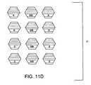
- a host imagecan also be filled in or created with “dots” or “blobs” where a set of the dots or blobs include fine lines or areas provided with metallic ink ( FIG. 11D ).
- the set of dots or blobscollectively provide a diffraction grating.
- Non-metallic ink dots or blobscan be intertwined with their metallic cousins to obfuscate the location of the metal dots—and consequently the location and design of the diffraction grating. (More generally, metallic dots can be laid down to provide a diffraction grating on a surface of a security or identification document.)
- identified areas of a diffraction gratingare used to guide metallic ink placement.
- Line spacing for a diffraction gratingis preferably determined with consideration of the illumination source (e.g., 60-75. GHz), so that the grating can accommodate the radiation or illumination wavelengths and provide a desired reflection beam or pattern response.
- the illumination sourcee.g. 60-75. GHz
- our linesbe on the order of about a millimeter or less, but other dimensions can be used according to a given design criteria. Distance between lines or dots can be adjusted to accommodate a desired reflection response, as is known to those of ordinary skill in the art.
- a pseudo-randomly generated spatial patternto help identify locations for placing metallic ink. Once locations are identified, metallic ink is laid down to provide a reflectance pattern.
- a key(perhaps assigned to an issuing authority) can be used to seed a pseudo-random pattern generator.
- FIGS. 11B and 11CStill other examples of arranging ink pairs are shown in FIGS. 11B and 11C .
- FIG. 11Bshows parallel lines, resulting in a somewhat typical diffraction grating formation. The straight lines contrast to the curvilinear grating shown in FIG. 11A .
- FIG. 11Cillustrates Metallic Blue (MB) ink that is over-printed or printed adjacent to selected segments of Blue (B) ink. This technique lays down a thin line or shadow at selected areas. This technique can be advantageously used to obfuscate locations of the Metallic Blue (MB) ink as well.
- MBMetallic Blue
- first and second inkswill have a transition area between first and second inks. This transition area allows for a gradual change between first ink and the second ink, which will help if inks noticeably differ in color or sheen.
- An excitation sourceexcites the diffraction grating, e.g., excites the Metallic Blue (MB) ink, as seen in FIG. 14 .
- An excitation sourcee.g., transceiver 40
- a handheld devicee.g., a keychain FOB, adapted cell phone, or the like
- a stationary locatione.g., point of sale location
- the excitation source 40emits a burst (or chirp) at a predetermined frequency (e.g., 72 Gigahertz).
- a predetermined frequencye.g., 72 Gigahertz.
- the diffraction grating or patternreflects the energy in a pattern in accordance with its design.
- the energy sourcesemits a chirp or burst that cycles through a range of frequencies (e.g., ramps up from 60 GHz to 75 GHz, and then perhaps back down to 60 GHz again).
- the chirp signalreflects from the diffraction grating or pattern in accordance with the grating's pattern.
- FIG. 14Illumination and resulting reflectance is shown, albeit in a simplified manner, in FIG. 14 .
- Transmitted radiationor energy
- solid linesand reflected radiation is shown in returning hashed lines.
- the excitation sourceincludes a receiver, perhaps even a MIMO (multiple inputs, multiple outputs) or SIMO (single input, multiple outputs) receiver, which includes multiple transmitters and receptors.
- a receiverperhaps even a MIMO (multiple inputs, multiple outputs) or SIMO (single input, multiple outputs) receiver, which includes multiple transmitters and receptors.
- An authenticator module 45determines a signature from reflected radiation patterns (e.g., reflection or beam patterns or a plurality of “peaks” representing reflection angles or phase relationships, etc.) over the cycled frequency range or a reflection pattern corresponding to a single reflection.
- the signatureneed not include all features from a reflected pattern, but instead may include one or more attributes of a received reflectance pattern. If using multiple transmitters and/or receivers, a signature may contemplate received interference patterns as well.
- the authenticator module 45determines whether the signature matches (or coincides within a predetermined tolerance) an expected signature.
- Different organizationse.g., different states when issuing driver's licenses
- Different types of documentscan be similarly distinguished (e.g., a first signature for a passport, and a second different signature for a visa, or a first signature for a first denomination of currency and a second different signature for a second denomination of currency).
- the authenticator module 45may cycle through a list of expected patterns to determine whether a received pattern matches at least one of the expected patterns.
- the identification document or security documentis authenticated when a signature matches (or coincides within a predetermined tolerance) an expected pattern or signal.
- the documentis considered suspect absent such a match.
- the metallic and non-metallic inksare arranged to provide both a diffraction grating and a digital watermark.
- LWMLine Width Modulation
- LCDLine Continuity Modulation
- the digital watermark patterncan be considered when designing a diffraction grating.
- Redundant encoding and error correction encodingcan help ensure that both a watermark signal and a diffraction grating are sufficiently produced.
- an identification documentincludes both a watermark (observable from scan data) and a diffraction grating (verified through received radiation patterns) conveyed through the same pair of inks.
- OLEDorganic light emitting diodes
- arrayor matrix
- An improvementis to provide an OLED display on an identification document or banknote.
- An OLED displaycan provided a luminous pattern, perhaps to show an expected currency denomination (e.g., text or number) or identification document type, or a graphic or seal.
- the displayed graphic or sealmay include a hidden signal, e.g., a digital watermark embedded therein.
- An optical scan of the OLEDwill include the hidden signal embedded in the graphic or seal.
- the luminous patterncan change. That is, the pattern can alternate between different patterns, or between text and patterns, etc.
- the OLED displayis provided on or in a first area of the document or banknote.
- the first areais a see-through, thin plastic window.
- the OLED displaycan be activated with an on-document power supply, e.g., a micro battery.
- the document or banknoteincludes piezoelectric device(s). Friction or movement of the document or banknote activates the piezoelectric devices, which creates a current to activate the OLED display.
- the OLED displayincludes or cooperates with passive circuitry; that is, circuitry that generates or responds to an electric field. The current is provided to the OLED display for activation.
- a document or banknoteincludes a contact, and power is transferred to the document or banknote through the contact. Another possible power source is solar energy or other light source.
- polymer thin film electronicsare provided to create a layer of plastic with an array of transistors and LEDs across the surface of a film.
- the film layeris integrated within a document structure (e.g., laminate onto core layer, for example).
- the circuitrycan be driven with a power supply, e.g., an on-document supply, such as a battery, or a contact or interface that receives power from an external power source. In either case the power energizes the LED array.
- the LED arraycan be used to display information, e.g., including information stored in the document (biometric information, demographic information, etc.). This is easy to imagine when the document includes electronic memory circuitry, e.g., such as is provided by a so-called smart card.
- Information from the memory circuitryis communicated to the LED array for display.
- paper thin documentse.g., banknotes
- a series of transistorse.g., organic TFT
- the transistorsform a memory cell, which can include information like a serial number, denomination, or hash of information printed on the document.
- Information carried by the document or banknotecan interact with external information supplied to the document through an interface.
- a documentthat includes a wireless interface.
- the documentreceives information through the interface.
- the informationis a key (e.g., of a key pair) that decrypts information encrypted on the card with the other key of the pair (e.g., a private/public key pair).
- the decrypted informationis displayed via the LED array. If the information is legible or expected the document is considered authentic, otherwise the document is considered suspect.
- a financial instrument or identification documentcomprising:
- OLEDorganic light emitting diode
- E2The financial instrument or identification document of E1, wherein the power supply comprises at least one of a battery, a passive-current generating device, solar or light conversion cell, and a piezoelectric device.
- E3The financial instrument or identification document of E1, wherein the electronic circuitry comprises memory with first information stored therein.
- E4The financial instrument or identification document of E3, wherein at least some of the first information is communicated to the OLED display via the electric circuitry for display thereon.
- E5.The financial instrument or identification document of E4, wherein the at least some of the first information that is communicated to the OLED display comprises at least one of a currency denomination, a graphic, seal, text, and number.
- E6The financial instrument or identification document of E4 wherein the at least some of the first information that is communicated to the OLED display comprises first display information and second display information, wherein the electronic circuitry provides timing of the first display information and the second display information so that the first display information is first displayed by the OLED display and then the second display information is displayed by the OLED display.
- E7The financial instrument or identification document of any one of E1-E6 wherein the instrument comprises at least one of a banknote, currency, check, note, draft, traveler's check, security interest, bond and certificate.
- An identification documentcomprising:
- LEDlight emitting diode
- E10The identification document of E8 wherein the electronic circuitry and LED matrix are carried by a thin film layer carried by the substrate.
- E13The financial instrument or identification document of E12, wherein the document or instrument further comprises an interface to receive second information.
- E14The financial instrument or identification document of E13, wherein the second information comprises a key to decrypt the first information prior to display on the LED display.
- E15The financial instrument or identification document of E3 wherein the substrate comprises at least one of printing, engraving and a photograph, and the first information comprises information that corresponds to or is redundant with the printing, engraving and photograph.
- E16The financial instrument or identification document of E15 wherein the substrate comprises multiple, separate layers.
- E17The financial instrument or identification document of any one of E1-E7 and E12-E16, wherein the instrument or document comprises at least one of a banknote, currency, check, note, draft, traveler's check, security interest, bond and certificate, driver's license, passport, visa and national id.
- a phenomenon of light interference in thin films(e.g., think of soapy water) is well understood and has been leveraged to create a broad array of security features since copying or altering objects with these types of “light interference” features is difficult.
- a simple example of this effectis shifting of spectral reflection of soapy water from a center point of 536 nm to 455 nm when the angle of incidence moves from normal to 45 degrees.
- This property of shifting spectral reflectioncan be used to create a digital watermark that can only be observed by viewing a watermarked image at an angle off normal (see FIG. 18 ).
- the modulation in spectral responsee.g., the watermark itself
- the modulation in spectral responseis created by varying a thickness of the film, which can be accomplished by any number of techniques including screening of the image (assuming it is being printed with pearlescent ink that displays these properties) or the film itself can be produced to vary in thickness.
- the documentis illuminated with white light and viewed at the specified angle.
- the recover processcan be augmented by using an equivalent of, e.g., a notch-filter or with illumination of a specific wavelength (e.g., truncating higher spectral frequencies, with reference to the dashed line in FIG. 18 ).
- this increase in spectral shifts, combined with more complex behaviors,can be used to impart a number of different behaviors on a watermark itself. For example:
- Retroreflection as phenomenahas been leverage from security applications (e.g., 3M's Confirm laminate) for safety clothing (e.g., a reflective vest for running at night).
- security applicationse.g., 3M's Confirm laminate
- safety clothinge.g., a reflective vest for running at night.
- the angle of reflection and spectral responsecan now be controlled through various manufacturing processes.
- a watermarkcan be encoded in retroreflective material. Similar to the prior embodiment using thin films, the watermark appears, disappears or changes (including yielding a different payload at different observation angles) as a function of the observed angle.
- a digital watermark equivalentis one that allows its payload (e.g., plural-bit message) to be encoded and embedded and then altered in the field after a watermarked image is produced on a substrate.
- payloade.g., plural-bit message
- remarkingFor statistics-based encoding or decoding, remarking “resets” the statistics of the image, so that the image can be re-marked. Remarking does have visual impacts though, so only a limited number of overwrites are currently possible.
- This addressable logic(or, more generally, the device's unique variations) are used to uniquely identify a specific circuit, used as a seed for a random number generator and even used as a key for a cryptographic process.
- Physical Random Functionsare based on what is believed to be fundamentally random process that is hard to control or predict; hence, the random features are hard to counterfeit.
- PRF featuresto create a machine-readable (or at least a machine-observable) feature that can be read in an automated fashion for printed security and identification documents.
- Security paper fibersare sometimes mixed in with raw paper pulp during paper manufacture. Some times the paper pulp is a cotton and linen concoction. (For identification documents, fibers or fluorescent particles can be mixed in a document substrate or layer during, e.g., a molding process.) Some currencies leverage color fibers (some of which are UV sensitive) in their paper making process, see, e.g., the Crane & Co. paper. Due to the introduction of the fibers in the paper pulp, the fibers are lodged in the substrate as opposed to being on the surface. The fiber's placement within the substrate protects them from undue soiling and wear. An exaggerated example of such fibers in a document is shown in FIG. 15 . These fibers find themselves arranged in a security document in a random manner—akin to Physical Random Functions seen in semiconductor devices.
- the random arrangement of such fibersallows for a calculation of a unique signature or fingerprint based on the fibers.
- a unique signature or fingerprintcan be observed with an optical imager (e.g., optical scanner or cell phone camera) or some other instrument typically used in the field (e.g., magnetic head for magnetic characteristics, IR or UV camera for out-of-visible spectrum characteristics, etc.).
- the signature or fingerprintcan include a representation of a spatial relationship of all fibers or a set of fibers. This representation, once determined, can be used to seed a number generator or hashing algorithm. The resulting number is the unique identifier.
- a slope of one or more of the security fiberscan be calculated and used as an identifier; related is a calculation of a second derivative for one or more of the fiber's shape (or slope curvature). The result is used as an identifier or as a seed to a number generator or hashing algorithm.
- identifying techniquesbased on the security fibers can be used as well.
- the result of such calculationsis an identifier that uniquely represents a security document based on the PRF nature of the security fibers.
- PRFsOne application using PRFs is tracking and monitoring. Documents are monitored as they flow through distribution centers. An optical scanner scans each document (or a sampling of such documents) as the documents flow by. The optical scan data is analyzed by a monitor (e.g., software or hardware monitor) to calculate unique identifiers for the respective documents.
- a monitore.g., software or hardware monitor
- a PRFcan be used to create a unique identifier for a document (e.g., a 256-bit identifier).
- a unique identifiercan be used in cooperation with digital watermarking and other machine-readable indicia.
- a digital watermark embedded in a documentmay carry a number resulting from PRF analysis.
- a PRFis read from an unprinted document substrate, e.g., via optical scanning of the substrate. Resulting optical scan data is analyzed and a unique identifier based on the PRFs is generated there from.
- the unique identifieris provided to an embedder.
- the embedderembeds the unique identifier as, e.g., a digital watermark or overt 2-D symbology. The watermarking or symbology is provided on the document during printing.
- a documentis modified each time it is inspected and validated.
- a documentis modified in some machine-recognizable fashion each time the document passes through a centralized facility.
- a documentcan be subtly reprinted to include another machine-readable component (e.g., a digital watermark component). Perhaps the component is only one or two bits (e.g., introduced through changing luminance characteristics of the document at predetermined areas, or relative to other digital watermark components). But the bit change indicates an inspection and successful validation.
- the documentis subsequently modified each time it is inspected and deemed valid. (A validity determination is made based on a successful calculation and verification of the PUF.
- the PUFis checked against a “watch list” of suspected identifiers, or can be compared to a machine-readable version of the same.).
- the documentincludes, e.g., photosensitive materials that change with exposure to the light or radiation.
- a method of monitoring for counterfeited documentscomprising:
- F2The method of F1 wherein the physically random function is determined from fibers found in the documents.
- a methodcomprising:
- PRFphysically random function
- first-line inspectionhas referred to inspection techniques that are carried out through visual inspection and/or touch. First-line inspection has been a cornerstone of security printing since its inception.
- a documentincludes extraordinarily small micro-print that is imperceptible to the naked human eye.
- a usere.g., at a point of sale location optically scans a document with her camera-equipped cell phone.
- Software executing on the cell phoneanalyzes the optical scan data, finds and then magnifies the micro-printing, and presents the magnified micro-printing via a device display.
- the softwaremay include a character recognition module that allows recognition of the micro-printing. If an error is found in the micro-printing (or if an expected error is not found) the device preferably prompts the user of such. Preferably, only those document regions including such micro-printing are provided via display for user inspection. (In some cases the ASCII values of micro-printing are hashed and compared against a predetermined or expected value. The user is notified if the calculated and expected values differ significantly.).
- the micro-printingis provided on the document surface in proximity to a fiducial or hash mark.
- the fiducialprovides a recognizable feature for the character recognition software.
- the fiducial's presencesignals an expected presence of micro-printing.
- the micro-printingis presented to a user via a device display.
- a documentin a second implementation, includes materials that fluoresce in the near-IR spectrum (e.g., many available inks have near-IR responses). While this fluorescence is beyond human perceptibly, many of today's devices (e.g., camera-equipped cell phones) are sensitive to this portion of the spectrum.
- the camerapicks up features conveyed in the near-IR, which are presented to the user via the display.
- the use of near-IR in the art of security printingis well known.
- One variation of this second implementationincludes a camera that picks up fluoresce or reflection from “hidden” features. These hidden features may be visible solely in the near-IR or may require an additional filter with a specific spectral response to highlight the feature.
- Another variation of this implementationinvolves illuminating a document with a light or strobe (a feature that is becoming common on cell phones & PDA's) that enable the feature to become visible.
- a third implementationharkens back to our above discussion of PRF's.
- a spatial mapping of the featuresis determined (see FIG. 16 ).
- the mappingis represented by an identifier or other characteristics.
- the identifier or characteristicsare provided as a machine-readable component (e.g., as a digital watermark component or payload).
- the digital watermarkmay also include a so-called orientation component, which is helpful in resolving image distortion such as rotation, scaling and translation. See, e.g., assignee's U.S. Pat. Nos. 6,704,869, 6,408,082, 6,122,403 and 5,862,260, which are each hereby incorporated by reference.
- a spatial mapping of the featuresis conveyed as a watermark orientation component, much like a mapping of fingerprint minutia discussed in assignee's U.S. Published Patent Application No. US 2005-0063562A1, published Mar. 24, 2005, which is hereby incorporated by reference.
- a userscans a document with her camera (e.g., cell phone or PDA).
- a watermark readerreads a watermark from the scan data to obtain the embedded identifier or characteristics.
- Cooperating softwarereconstructs an expected, relative spatial placement of the security fibers based on the embedded identifier or characteristics.
- the expected spatial placementis provided to the user via the device display.
- the presentationmay include, e.g., a graphical representation of an expected placement of security fibers relative to the document (see FIG. 17 ).
- the representationcan include dots, lines, marks, etc.
- an image of the documentis shown in the display (as captured by the device) and a graphical overlay is provided over the document to show the expected placement of the security fibers.
- a usercan visually check the document to determine accurate placement.
- PRF indicatorse.g., security fibers
- Another variationautomatically determines an actual placement of PRF indicators (e.g., security fibers) and presents via a device display the actual placement vs. the expected placement.
- the actual placement of PRF indicatorsis found through, e.g., analysis of optical scan data.
- a watermarkmay reveal an expected location, shape or details of other document features such as designs, seals, etc.
- a watermark payloadmay be secured through cryptographic means to provide additional security.
- a public keyis provided to a user's device to decode a watermark payload. The public key can be used to validate a digital signature issued by a document issuing authority for the document being inspected. The hash used to create the digital signature would be based on a PRF or PUF. The digital signature would be created and embedded into a machine readable feature during printing.
- a fourth implementationrelies on so-called high-resolution watermarks (fragile, robust, tamper-evident, etc.). These watermarks may only be detectable through high resolution scanning. Resolutions of 10K DPI are common in security printing, this allows for machine readable features of the same resolution. By operating at this resolution, successful attacks would be required to operate at a similar resolution if not 2 ⁇ (Nyquist). This places the features well outside the range of current imaging workflows (typically 1200-4800DPI) and hence outside of all but the most specialized of equipment usually reserved for security printers (e.g., Simultan Printing Presses, Jura RIPs, etc.). This frequency is also in a similar band to where naturally occurring PRF's typically appear (ink bleed, dot gain, voids, etc.).
- a fifth implementationrelies on audible feedback.
- a toneis generated by a device (e.g., cell phone, PDA, etc.) as an imager sweeps across a document. The tone is triggered, e.g., when a watermark is detected and/or when the watermark's payload matches or otherwise corresponds to the predetermined PRF characteristics.
- an audible scalee.g., think ring-tone
- the ring tonewill only sound or will vary in sound depending on the speed of the optical sweep (a simple gyroscope with speed measurement in the device can help facilitate this functionality).
- speed of optical sweep and watermark/PRF detectioncan be combined to generate a predetermined sound.
- An important criteria in many of the above implementationsis to leave the decision process of whether a document is authentic to a human observer, and not to a device. For example, if authentication relies solely on a device flashing a green light, signaling that a document is authentic, counterfeiting attacks will target the device. Such attacks might render device-determined authentication indications suspect.
- a method of authenticating a security or identification document with a handheld computing devicecomprising:
- G2The method of G1 wherein the document further comprises a micro-printed fiducial.
- G3The method of G2 wherein the micro-printing is recognized at least in part through identification of the fidicual.
- a handheld computing devicecomprising:
- said memorycomprises executable instructions stored therein for execution by the processing circuitry, said instructions comprising instructions to carry out the method of any one of F1-F3.
- a method of authenticating a security or identification document with a handheld computing devicecomprising:
- the methods, processes, and systems described abovemay be implemented in hardware, software or a combination of hardware and software.
- the methods and processes described abovemay be implemented in programs executed from a system's memory (a computer readable medium, such as an electronic, optical or magnetic storage device).
Landscapes
- Physics & Mathematics (AREA)
- General Physics & Mathematics (AREA)
- Engineering & Computer Science (AREA)
- Computer Security & Cryptography (AREA)
- Toxicology (AREA)
- General Health & Medical Sciences (AREA)
- Health & Medical Sciences (AREA)
- Theoretical Computer Science (AREA)
- Editing Of Facsimile Originals (AREA)
- Image Processing (AREA)
- Multimedia (AREA)
- Credit Cards Or The Like (AREA)
- Diffracting Gratings Or Hologram Optical Elements (AREA)
Abstract
Description
- Increased Fragility: Frequency band where a watermark appears is tightly controlled, such that only with very narrow-band illumination or with a notch filter can the watermark be read.
- Tamper Evidence: By imparting fragility in the structure itself (e.g., varying the adhesives between films) a watermark is designed such that a component of the watermark is carried in the fragile film, such that if the document is tampered with and the film was separated, the watermark would no longer read. A variant of this is having a watermark appear if tampering occurs. This can be abstracted to create a system wherein integrity of a thin-film based security feature can validated in an automated fashion, layer by layer.
- Interdependence: Similar to physical security, a watermark can only be read by knowing the “recipe” of where and how to illuminate a structure to recover the watermark. This recipe may include multiple observation points, illumination sources and filtering. All requiring that all the observed spectral shifts are co-located such that the watermark is still readable (e.g., think of plate-registration, but taken to three dimensions. Each layer must be registered (X,Y) and the thickness has to be correct (Z)).
- Appearance of disappearance of wave-bands: In another embodiment, a perceived double to single waveband shift (e.g., both spectral responses shift, but one might shift into UV, hence making it non-visible) is used to weaken or allow a watermark to appear.
Retroreflection
- Encode watermark template in a substrate, but add/modify message to the substrate after production by using techniques such as is used in DCards, where the substrate itself is heated locally and causes a “browning” of the PVC substrate where heated.
- Destroy specific “cells” within retro-reflective laminate to locally change the spectral response when viewed at a specific angle.
Claims (17)
Priority Applications (11)
| Application Number | Priority Date | Filing Date | Title |
|---|---|---|---|
| US11/270,802US7856116B2 (en) | 2004-11-09 | 2005-11-08 | Authenticating identification and security documents |
| US11/675,461US20070201720A1 (en) | 2004-11-09 | 2007-02-15 | Authenticating Signals and Identification and Security Documents |
| US12/870,547US20110102143A1 (en) | 2004-11-09 | 2010-08-27 | Authenticating Signals and Identification and Security Documents |
| US12/970,629US8194919B2 (en) | 2004-11-09 | 2010-12-16 | Authenticating identification and security documents |
| US13/267,698US20120074220A1 (en) | 2004-11-09 | 2011-10-06 | Authenticating Identification and Security Documents With Cell Phones |
| US13/276,103US20120126017A1 (en) | 2004-11-09 | 2011-10-18 | Hiding Auxiliary Data with Line Structure Modification |
| US13/488,942US9087376B2 (en) | 2004-11-09 | 2012-06-05 | Authenticating identification and security documents and other objects |
| US14/805,122US9718296B2 (en) | 2004-11-09 | 2015-07-21 | Authenticating identification and security documents and other objects |
| US15/387,145US20170103493A1 (en) | 2004-11-09 | 2016-12-21 | Authenticating printed objects |
| US15/650,447US10543711B2 (en) | 2004-11-09 | 2017-07-14 | Authenticating identification and security documents and other objects |
| US16/752,250US11548310B2 (en) | 2004-11-09 | 2020-01-24 | Authenticating identification and security documents and other objects |
Applications Claiming Priority (5)
| Application Number | Priority Date | Filing Date | Title |
|---|---|---|---|
| US62652904P | 2004-11-09 | 2004-11-09 | |
| US65181405P | 2005-02-10 | 2005-02-10 | |
| US67077305P | 2005-04-11 | 2005-04-11 | |
| US67479305P | 2005-04-25 | 2005-04-25 | |
| US11/270,802US7856116B2 (en) | 2004-11-09 | 2005-11-08 | Authenticating identification and security documents |
Related Child Applications (2)
| Application Number | Title | Priority Date | Filing Date |
|---|---|---|---|
| US11/675,461ContinuationUS20070201720A1 (en) | 2004-11-09 | 2007-02-15 | Authenticating Signals and Identification and Security Documents |
| US12/970,629ContinuationUS8194919B2 (en) | 2004-11-09 | 2010-12-16 | Authenticating identification and security documents |
Publications (2)
| Publication Number | Publication Date |
|---|---|
| US20060115110A1 US20060115110A1 (en) | 2006-06-01 |
| US7856116B2true US7856116B2 (en) | 2010-12-21 |
Family
ID=36337170
Family Applications (11)
| Application Number | Title | Priority Date | Filing Date |
|---|---|---|---|
| US11/270,802Active2028-06-03US7856116B2 (en) | 2004-11-09 | 2005-11-08 | Authenticating identification and security documents |
| US11/675,461AbandonedUS20070201720A1 (en) | 2004-11-09 | 2007-02-15 | Authenticating Signals and Identification and Security Documents |
| US12/870,547AbandonedUS20110102143A1 (en) | 2004-11-09 | 2010-08-27 | Authenticating Signals and Identification and Security Documents |
| US12/970,629ActiveUS8194919B2 (en) | 2004-11-09 | 2010-12-16 | Authenticating identification and security documents |
| US13/267,698AbandonedUS20120074220A1 (en) | 2004-11-09 | 2011-10-06 | Authenticating Identification and Security Documents With Cell Phones |
| US13/276,103AbandonedUS20120126017A1 (en) | 2004-11-09 | 2011-10-18 | Hiding Auxiliary Data with Line Structure Modification |
| US13/488,942ActiveUS9087376B2 (en) | 2004-11-09 | 2012-06-05 | Authenticating identification and security documents and other objects |
| US14/805,122ActiveUS9718296B2 (en) | 2004-11-09 | 2015-07-21 | Authenticating identification and security documents and other objects |
| US15/387,145AbandonedUS20170103493A1 (en) | 2004-11-09 | 2016-12-21 | Authenticating printed objects |
| US15/650,447Active2025-11-10US10543711B2 (en) | 2004-11-09 | 2017-07-14 | Authenticating identification and security documents and other objects |
| US16/752,250ActiveUS11548310B2 (en) | 2004-11-09 | 2020-01-24 | Authenticating identification and security documents and other objects |
Family Applications After (10)
| Application Number | Title | Priority Date | Filing Date |
|---|---|---|---|
| US11/675,461AbandonedUS20070201720A1 (en) | 2004-11-09 | 2007-02-15 | Authenticating Signals and Identification and Security Documents |
| US12/870,547AbandonedUS20110102143A1 (en) | 2004-11-09 | 2010-08-27 | Authenticating Signals and Identification and Security Documents |
| US12/970,629ActiveUS8194919B2 (en) | 2004-11-09 | 2010-12-16 | Authenticating identification and security documents |
| US13/267,698AbandonedUS20120074220A1 (en) | 2004-11-09 | 2011-10-06 | Authenticating Identification and Security Documents With Cell Phones |
| US13/276,103AbandonedUS20120126017A1 (en) | 2004-11-09 | 2011-10-18 | Hiding Auxiliary Data with Line Structure Modification |
| US13/488,942ActiveUS9087376B2 (en) | 2004-11-09 | 2012-06-05 | Authenticating identification and security documents and other objects |
| US14/805,122ActiveUS9718296B2 (en) | 2004-11-09 | 2015-07-21 | Authenticating identification and security documents and other objects |
| US15/387,145AbandonedUS20170103493A1 (en) | 2004-11-09 | 2016-12-21 | Authenticating printed objects |
| US15/650,447Active2025-11-10US10543711B2 (en) | 2004-11-09 | 2017-07-14 | Authenticating identification and security documents and other objects |
| US16/752,250ActiveUS11548310B2 (en) | 2004-11-09 | 2020-01-24 | Authenticating identification and security documents and other objects |
Country Status (3)
| Country | Link |
|---|---|
| US (11) | US7856116B2 (en) |
| EP (1) | EP1825419A4 (en) |
| WO (1) | WO2006053023A2 (en) |
Cited By (38)
| Publication number | Priority date | Publication date | Assignee | Title |
|---|---|---|---|---|
| US20080267510A1 (en)* | 2007-04-26 | 2008-10-30 | Bowe Bell + Howell Company | Document processing system control using document feature analysis for identification |
| US20090324061A1 (en)* | 2008-06-27 | 2009-12-31 | Christopher Odgers | Digital media with token for analog reconversion detection |
| US20110142280A1 (en)* | 2004-11-09 | 2011-06-16 | Rodriguez Tony F | Authenticating Identification and Security Documents |
| US8010632B2 (en) | 1993-11-18 | 2011-08-30 | Digimarc Corporation | Steganographic encoding for video and images |
| US8280101B2 (en) | 1995-08-09 | 2012-10-02 | Digimarc Corporation | Identification documents and authentication of such documents |
| US8411898B2 (en) | 1995-05-08 | 2013-04-02 | Digimarc Corporation | Digital authentication with analog documents |
| US20140217173A1 (en)* | 2010-03-10 | 2014-08-07 | Linksmart Technologies Pvt. Ltd. | Label for enabling verification of an object |
| US8917930B2 (en) | 2012-05-08 | 2014-12-23 | Hewlett-Packard Development Company, L.P. | Selecting metrics for substrate classification |
| US20160350890A1 (en)* | 2015-05-28 | 2016-12-01 | Fujitsu Limited | Information detecting device, information detecting system, and information detecting method |
| US9591022B2 (en) | 2014-12-17 | 2017-03-07 | The Boeing Company | Computer defenses and counterattacks |
| US9665818B1 (en) | 2016-06-21 | 2017-05-30 | Bank Of America Corporation | Organic light emitting diode (“OLED”) universal plastic |
| US9690967B1 (en) | 2015-10-29 | 2017-06-27 | Digimarc Corporation | Detecting conflicts between multiple different encoded signals within imagery |
| US9697388B1 (en) | 2016-06-14 | 2017-07-04 | Bank Of America Corporation | Unfoldable OLED reader/displays for the visually-impaired |
| US9747539B1 (en) | 2016-06-21 | 2017-08-29 | Bank Of America Corporation | Organic light emitting diode (“OLED”) travel card |
| US9760124B1 (en) | 2016-07-11 | 2017-09-12 | Bank Of America Corporation | Organic light emitting diode (“OLED”)-based displays |
| US9858558B1 (en) | 2016-07-08 | 2018-01-02 | Bank Of America Corporation | Multi-screen automated teller machine (ATM)/automated teller assist (ATA) machines for use by wheelchair users |
| US20180211264A1 (en)* | 2015-07-31 | 2018-07-26 | Silvio Micali | Counterfeit prevention |
| US10043183B2 (en) | 2016-08-30 | 2018-08-07 | Bank Of America Corporation | Organic light emitting diode (“OLED”) visual authentication circuit board |
| US10163154B2 (en) | 2016-06-21 | 2018-12-25 | Bank Of America Corporation | OLED (“organic light emitting diode”) teller windows |
| US10176676B2 (en) | 2016-09-23 | 2019-01-08 | Bank Of America Corporation | Organic light emitting diode (“OLED”) display with quick service terminal (“QST”) functionality |
| US10339531B2 (en) | 2016-06-10 | 2019-07-02 | Bank Of America Corporation | Organic light emitting diode (“OLED”) security authentication system |
| US20190306588A1 (en)* | 2018-03-29 | 2019-10-03 | Ncr Corporation | Media content proof of play over optical medium |
| US10460135B1 (en) | 2016-06-21 | 2019-10-29 | Bank Of America Corporation | Foldable organic light emitting diode (“OLED”) purchasing instrument reader |
| US10565415B2 (en) | 2016-02-23 | 2020-02-18 | Digimarc Corporation | Scanner with control logic for resolving package labeling conflicts |
| US10580068B2 (en) | 2016-07-11 | 2020-03-03 | Bank Of America Corporation | OLED-based secure monitoring of valuables |
| US10594689B1 (en) | 2015-12-04 | 2020-03-17 | Digimarc Corporation | Robust encoding of machine readable information in host objects and biometrics, and associated decoding and authentication |
| US20200242439A1 (en)* | 2017-04-27 | 2020-07-30 | Silvio Micali | Counterfeit prevention |
| US10783336B2 (en) | 2016-06-21 | 2020-09-22 | Bank Of America Corporation | Reshape-able OLED device for positioning payment instrument |
| US10789438B1 (en) | 2019-02-08 | 2020-09-29 | Digimarc Corporation | Detecting conflicts between multiple different encoded signals within imagery, using only a subset of available image data |
| US10803374B2 (en)* | 2016-08-08 | 2020-10-13 | Silvio Micali | Counterfeit prevention |
| US10880451B2 (en) | 2018-06-08 | 2020-12-29 | Digimarc Corporation | Aggregating detectability metrics to determine signal robustness |
| US10929943B2 (en) | 2016-09-15 | 2021-02-23 | Digimarc Corporation | Detecting conflicts between multiple different encoded signals within imagery |
| US10970027B2 (en) | 2016-06-21 | 2021-04-06 | Bank Of America Corporation | Combination organic light emitting diode (“OLED”) device |
| US11138488B2 (en) | 2019-06-26 | 2021-10-05 | Bank Of America Corporation | Organic light emitting diode (“OLED”) single-use payment instrument |
| US11250535B1 (en) | 2019-02-08 | 2022-02-15 | Digimarc Corporation | Detecting conflicts between multiple different encoded signals within imagery, using only a subset of available image data, and robustness checks |
| US11636565B1 (en) | 2019-07-24 | 2023-04-25 | Digimarc Corporation | Tamper detection arrangements, and point of sales systems employing same |
| US11741332B2 (en) | 2017-04-27 | 2023-08-29 | Silvio Micali | Securing cryptographic keys |
| US11922532B2 (en) | 2020-01-15 | 2024-03-05 | Digimarc Corporation | System for mitigating the problem of deepfake media content using watermarking |
Families Citing this family (167)
| Publication number | Priority date | Publication date | Assignee | Title |
|---|---|---|---|---|
| US20050097046A1 (en) | 2003-10-30 | 2005-05-05 | Singfield Joy S. | Wireless electronic check deposit scanning and cashing machine with web-based online account cash management computer application system |
| AU2005281043B2 (en)* | 2004-09-07 | 2009-01-08 | National Printing Bureau, Incorporated Administrative Agency | OVD examination method and examination instrument |
| US8287993B2 (en)* | 2004-09-15 | 2012-10-16 | Crane & Co., Inc. | Security device and novel anti-counterfeit product employing same |
| US8224018B2 (en)* | 2006-01-23 | 2012-07-17 | Digimarc Corporation | Sensing data from physical objects |
| CN101523408B (en) | 2006-01-23 | 2013-11-20 | 数字标记公司 | A method of identifying objects |
| DE102006031422A1 (en)* | 2006-07-05 | 2008-01-10 | Bundesdruckerei Gmbh | Value or security document with a display device |
| US11019007B1 (en)* | 2006-07-13 | 2021-05-25 | United Services Automobile Association (Usaa) | Systems and methods for providing electronic official documents |
| US7792324B2 (en)* | 2006-08-11 | 2010-09-07 | Xerox Corporation | System and method for embedding miniature security marks |
| US7676058B2 (en)* | 2006-08-11 | 2010-03-09 | Xerox Corporation | System and method for detection of miniature security marks |
| US8056821B2 (en) | 2006-10-18 | 2011-11-15 | Xerox Corporation | Security marks simulating natural defects for embedding information in documents |
| US8351677B1 (en) | 2006-10-31 | 2013-01-08 | United Services Automobile Association (Usaa) | Systems and methods for remote deposit of checks |
| US7876949B1 (en) | 2006-10-31 | 2011-01-25 | United Services Automobile Association | Systems and methods for remote deposit of checks |
| US8799147B1 (en) | 2006-10-31 | 2014-08-05 | United Services Automobile Association (Usaa) | Systems and methods for remote deposit of negotiable instruments with non-payee institutions |
| US8708227B1 (en) | 2006-10-31 | 2014-04-29 | United Services Automobile Association (Usaa) | Systems and methods for remote deposit of checks |
| US7885451B1 (en) | 2006-10-31 | 2011-02-08 | United Services Automobile Association (Usaa) | Systems and methods for displaying negotiable instruments derived from various sources |
| US7873200B1 (en) | 2006-10-31 | 2011-01-18 | United Services Automobile Association (Usaa) | Systems and methods for remote deposit of checks |
| US8750593B2 (en)* | 2006-11-07 | 2014-06-10 | Pitney Bowes Inc. | Substitute check incorporating encoded indication of security feature in original check |
| US8215553B2 (en)* | 2006-11-15 | 2012-07-10 | Digimarc Corporation | Physical credentials and related methods |
| US7991157B2 (en)* | 2006-11-16 | 2011-08-02 | Digimarc Corporation | Methods and systems responsive to features sensed from imagery or other data |
| DE102007002385A1 (en)* | 2007-01-10 | 2008-07-24 | Bundesdruckerei Gmbh | Document with an optical transmitter |
| US7949175B2 (en)* | 2007-01-23 | 2011-05-24 | Xerox Corporation | Counterfeit deterrence using dispersed miniature security marks |
| US7864979B2 (en) | 2007-01-23 | 2011-01-04 | Xerox Corporation | System and method for embedding dispersed miniature security marks |
| US10380559B1 (en) | 2007-03-15 | 2019-08-13 | United Services Automobile Association (Usaa) | Systems and methods for check representment prevention |
| US8959033B1 (en) | 2007-03-15 | 2015-02-17 | United Services Automobile Association (Usaa) | Systems and methods for verification of remotely deposited checks |
| US8538124B1 (en) | 2007-05-10 | 2013-09-17 | United Services Auto Association (USAA) | Systems and methods for real-time validation of check image quality |
| US8433127B1 (en) | 2007-05-10 | 2013-04-30 | United Services Automobile Association (Usaa) | Systems and methods for real-time validation of check image quality |
| US20080283612A1 (en)* | 2007-05-14 | 2008-11-20 | Spear Usa, Llc | System and method for determining product counterfeiting and diversion |
| US8687241B2 (en)* | 2007-06-06 | 2014-04-01 | Hewlett-Packard Development Company, L.P. | Method for security printing |
| JP2009005312A (en)* | 2007-06-25 | 2009-01-08 | Canon Inc | Image processing apparatus, image processing method, computer program, and storage medium |
| JP4552156B2 (en)* | 2007-09-26 | 2010-09-29 | 富士ゼロックス株式会社 | Image forming system and program |
| US9058512B1 (en) | 2007-09-28 | 2015-06-16 | United Services Automobile Association (Usaa) | Systems and methods for digital signature detection |
| US9892454B1 (en) | 2007-10-23 | 2018-02-13 | United Services Automobile Association (Usaa) | Systems and methods for obtaining an image of a check to be deposited |
| US9159101B1 (en) | 2007-10-23 | 2015-10-13 | United Services Automobile Association (Usaa) | Image processing |
| US8358826B1 (en) | 2007-10-23 | 2013-01-22 | United Services Automobile Association (Usaa) | Systems and methods for receiving and orienting an image of one or more checks |
| US9898778B1 (en) | 2007-10-23 | 2018-02-20 | United Services Automobile Association (Usaa) | Systems and methods for obtaining an image of a check to be deposited |
| US7996315B1 (en) | 2007-10-30 | 2011-08-09 | United Services Automobile Association (Usaa) | Systems and methods to modify a negotiable instrument |
| US8001051B1 (en) | 2007-10-30 | 2011-08-16 | United Services Automobile Association (Usaa) | Systems and methods to modify a negotiable instrument |
| US7996316B1 (en) | 2007-10-30 | 2011-08-09 | United Services Automobile Association | Systems and methods to modify a negotiable instrument |
| US7996314B1 (en) | 2007-10-30 | 2011-08-09 | United Services Automobile Association (Usaa) | Systems and methods to modify a negotiable instrument |
| US8290237B1 (en) | 2007-10-31 | 2012-10-16 | United Services Automobile Association (Usaa) | Systems and methods to use a digital camera to remotely deposit a negotiable instrument |
| US8320657B1 (en) | 2007-10-31 | 2012-11-27 | United Services Automobile Association (Usaa) | Systems and methods to use a digital camera to remotely deposit a negotiable instrument |
| EP2056258A1 (en)* | 2007-11-05 | 2009-05-06 | Siemens Aktiengesellschaft | Valuable document, especially stamps, with a safety element |
| DE102007058680A1 (en)* | 2007-11-05 | 2009-05-07 | Siemens Ag | Counterfeit-proof value document and method for its verification |
| US7900822B1 (en) | 2007-11-06 | 2011-03-08 | United Services Automobile Association (Usaa) | Systems, methods, and apparatus for receiving images of one or more checks |
| US7896232B1 (en) | 2007-11-06 | 2011-03-01 | United Services Automobile Association (Usaa) | Systems, methods, and apparatus for receiving images of one or more checks |
| DE102007000883A1 (en)* | 2007-11-12 | 2009-05-14 | Bundesdruckerei Gmbh | Document with an integrated display device |
| DE102007000874A1 (en)* | 2007-11-12 | 2009-05-14 | Bundesdruckerei Gmbh | Document with an integrated display device |
| DE102007000875A1 (en)* | 2007-11-12 | 2009-05-14 | Bundesdruckerei Gmbh | Document with an integrated display device |
| DE102007000890B4 (en) | 2007-11-12 | 2014-06-05 | Bundesdruckerei Gmbh | Document with an integrated display device |
| US10380562B1 (en) | 2008-02-07 | 2019-08-13 | United Services Automobile Association (Usaa) | Systems and methods for mobile deposit of negotiable instruments |
| EP2306888A1 (en)* | 2008-04-14 | 2011-04-13 | Optovue, Inc. | Method of eye registration for optical coherence tomography |
| EP2281280A1 (en)* | 2008-05-02 | 2011-02-09 | De La Rue International Limited | Method and apparatus for determining authenticity |
| GB2472955B (en)* | 2008-05-22 | 2013-02-13 | Hewlett Packard Development Co | Security printing analysis system and method for enhancing security printing |
| US8351678B1 (en) | 2008-06-11 | 2013-01-08 | United Services Automobile Association (Usaa) | Duplicate check detection |
| US9113231B2 (en) | 2008-08-19 | 2015-08-18 | Thomson Licensing | Changeable block list |
| US8422758B1 (en) | 2008-09-02 | 2013-04-16 | United Services Automobile Association (Usaa) | Systems and methods of check re-presentment deterrent |
| US10504185B1 (en)* | 2008-09-08 | 2019-12-10 | United Services Automobile Association (Usaa) | Systems and methods for live video financial deposit |
| US7974899B1 (en) | 2008-09-30 | 2011-07-05 | United Services Automobile Association (Usaa) | Atomic deposit transaction |
| US7962411B1 (en) | 2008-09-30 | 2011-06-14 | United Services Automobile Association (Usaa) | Atomic deposit transaction |
| US8275710B1 (en) | 2008-09-30 | 2012-09-25 | United Services Automobile Association (Usaa) | Systems and methods for automatic bill pay enrollment |
| US7885880B1 (en) | 2008-09-30 | 2011-02-08 | United Services Automobile Association (Usaa) | Atomic deposit transaction |
| US8391599B1 (en) | 2008-10-17 | 2013-03-05 | United Services Automobile Association (Usaa) | Systems and methods for adaptive binarization of an image |
| US7949587B1 (en) | 2008-10-24 | 2011-05-24 | United States Automobile Association (USAA) | Systems and methods for financial deposits by electronic message |
| US7970677B1 (en) | 2008-10-24 | 2011-06-28 | United Services Automobile Association (Usaa) | Systems and methods for financial deposits by electronic message |
| US8452689B1 (en) | 2009-02-18 | 2013-05-28 | United Services Automobile Association (Usaa) | Systems and methods of check detection |
| US10956728B1 (en) | 2009-03-04 | 2021-03-23 | United Services Automobile Association (Usaa) | Systems and methods of check processing with background removal |
| US8817090B2 (en)* | 2009-04-02 | 2014-08-26 | GM Global Technology Operations LLC | Luminance uniformity compensation of vector projection display |
| US8890892B2 (en)* | 2009-04-24 | 2014-11-18 | Pixar | System and method for steganographic image display |
| US8817043B2 (en)* | 2009-04-24 | 2014-08-26 | Disney Enterprises, Inc. | System and method for selective viewing of a hidden presentation within a displayed presentation |
| US9749607B2 (en) | 2009-07-16 | 2017-08-29 | Digimarc Corporation | Coordinated illumination and image signal capture for enhanced signal detection |
| FR2948217B1 (en) | 2009-07-17 | 2011-11-11 | Arjowiggins Security | SECURITY ELEMENT WITH PARALLAX EFFECT |
| US8542921B1 (en) | 2009-07-27 | 2013-09-24 | United Services Automobile Association (Usaa) | Systems and methods for remote deposit of negotiable instrument using brightness correction |
| US9779392B1 (en) | 2009-08-19 | 2017-10-03 | United Services Automobile Association (Usaa) | Apparatuses, methods and systems for a publishing and subscribing platform of depositing negotiable instruments |
| US8977571B1 (en) | 2009-08-21 | 2015-03-10 | United Services Automobile Association (Usaa) | Systems and methods for image monitoring of check during mobile deposit |
| US8699779B1 (en) | 2009-08-28 | 2014-04-15 | United Services Automobile Association (Usaa) | Systems and methods for alignment of check during mobile deposit |
| JP5753200B2 (en)* | 2010-02-09 | 2015-07-22 | トムソン ライセンシングThomson Licensing | Watermark detection using a propagation map |
| US10664940B2 (en) | 2010-03-05 | 2020-05-26 | Digimarc Corporation | Signal encoding to reduce perceptibility of changes over time |
| US8971567B2 (en)* | 2010-03-05 | 2015-03-03 | Digimarc Corporation | Reducing watermark perceptibility and extending detection distortion tolerances |
| EP2545496A4 (en)* | 2010-03-10 | 2017-08-23 | LinkSmart Technologies Pvt. Ltd. | A method of content authentication inside a sealed box using special labels |
| WO2011121928A1 (en)* | 2010-03-31 | 2011-10-06 | 日本電気株式会社 | Digital content management system, verification device, programs therefor, and data processing method |
| US9129340B1 (en) | 2010-06-08 | 2015-09-08 | United Services Automobile Association (Usaa) | Apparatuses, methods and systems for remote deposit capture with enhanced image detection |
| KR101760663B1 (en) | 2010-06-14 | 2017-08-04 | 트루테그 테크놀로지스, 인코포레이티드 | System for verifying an item in a package |
| US9262738B2 (en)* | 2010-06-24 | 2016-02-16 | Yariv Glazer | Methods of marking products and products produced by such methods |
| US20120235785A1 (en)* | 2011-03-17 | 2012-09-20 | Motorola Mobility, Inc. | Wireless communication device and method with intelligent authentication |
| US10366299B2 (en)* | 2011-10-25 | 2019-07-30 | Bull Hn Information Systems, Inc. | Sorting/scanning system camera upgrade apparatus with backwards compatibility |
| DE102011119821A1 (en) | 2011-12-01 | 2013-06-06 | Bundesdruckerei Gmbh | Electro-optical security element |
| US10380565B1 (en) | 2012-01-05 | 2019-08-13 | United Services Automobile Association (Usaa) | System and method for storefront bank deposits |
| US20150169928A1 (en) | 2012-03-01 | 2015-06-18 | Sys-Tech Solutions, Inc. | Methods and a system for verifying the identity of a printed item |
| RS57033B1 (en) | 2012-03-01 | 2018-05-31 | Sys Tech Solutions Inc | Unique identification information from marked features |
| US20150379321A1 (en) | 2012-03-01 | 2015-12-31 | Sys-Tech Solutions, Inc. | Methods and a system for verifying the authenticity of a mark |
| US9593982B2 (en) | 2012-05-21 | 2017-03-14 | Digimarc Corporation | Sensor-synchronized spectrally-structured-light imaging |
| WO2013188807A2 (en)* | 2012-06-14 | 2013-12-19 | Digimarc Corporation | Methods and systems for signal processing |
| EP2618323B1 (en)* | 2012-08-21 | 2018-06-13 | LinkSmart Technologies Pvt. Ltd. | Label for enabling verification of an object |
| WO2014059439A1 (en)* | 2012-10-12 | 2014-04-17 | Document Security Systems, Inc. | System and method for analysis and authentication using a smart device |
| US10051156B2 (en) | 2012-11-07 | 2018-08-14 | Xerox Corporation | System and method for producing correlation and gloss mark images |
| US10552810B1 (en) | 2012-12-19 | 2020-02-04 | United Services Automobile Association (Usaa) | System and method for remote deposit of financial instruments |
| US9148544B2 (en)* | 2012-12-21 | 2015-09-29 | Nvidia Corporation | System, process, and computer program product for implementing a document scanner in a hand-held device |
| US10373470B2 (en) | 2013-04-29 | 2019-08-06 | Intelliview Technologies, Inc. | Object detection |
| US9621760B2 (en)* | 2013-06-07 | 2017-04-11 | Digimarc Corporation | Information coding and decoding in spectral differences |
| US11138578B1 (en)* | 2013-09-09 | 2021-10-05 | United Services Automobile Association (Usaa) | Systems and methods for remote deposit of currency |
| US9193201B2 (en) | 2013-09-18 | 2015-11-24 | Xerox Corporation | System and method for producing color shifting or gloss effect and recording medium with color shifting or gloss effect |
| US9106847B2 (en) | 2013-09-18 | 2015-08-11 | Xerox Corporation | System and method for producing color shifting or gloss effect and recording medium with color shifting or gloss effect |
| US9319557B2 (en)* | 2013-09-18 | 2016-04-19 | Xerox Corporation | System and method for producing color shifting or gloss effect and recording medium with color shifting or gloss effect |
| US9286514B1 (en) | 2013-10-17 | 2016-03-15 | United Services Automobile Association (Usaa) | Character count determination for a digital image |
| WO2015082332A1 (en)* | 2013-12-02 | 2015-06-11 | Leonhard Kurz Stiftung & Co. Kg | Method for authenticating a security element, and optically variable security element |
| US10424038B2 (en) | 2015-03-20 | 2019-09-24 | Digimarc Corporation | Signal encoding outside of guard band region surrounding text characters, including varying encoding strength |
| US9635378B2 (en) | 2015-03-20 | 2017-04-25 | Digimarc Corporation | Sparse modulation for robust signaling and synchronization |
| DE102014003005A1 (en)* | 2014-02-28 | 2015-09-03 | Giesecke & Devrient Gmbh | Method for determining a sorting result for a value document and means for carrying out the method |
| US20150262446A1 (en)* | 2014-03-13 | 2015-09-17 | Daniel Taylor | Currency inspection using mobile device and attachments |
| CA2847707C (en)* | 2014-03-28 | 2021-03-30 | Intelliview Technologies Inc. | Leak detection |
| US9691211B2 (en)* | 2014-07-03 | 2017-06-27 | Seiko Epson Corporation | Image processing apparatus, image processing method, and program |
| US10943357B2 (en) | 2014-08-19 | 2021-03-09 | Intelliview Technologies Inc. | Video based indoor leak detection |
| KR20170092522A (en)* | 2014-09-08 | 2017-08-11 | 더 리서치 파운데이션 포 더 스테이트 유니버시티 오브 뉴욕 | Metallic gratings and measurement methods thereof |
| RU2684498C2 (en)* | 2014-12-24 | 2019-04-09 | Банко Де Мехико | Method of certification and authentication of protected documents based on measurement result of deviations of relative position in different processes involved in making such security documents |
| US9940572B2 (en) | 2015-02-17 | 2018-04-10 | Sys-Tech Solutions, Inc. | Methods and a computing device for determining whether a mark is genuine |
| US9832338B2 (en)* | 2015-03-06 | 2017-11-28 | Intel Corporation | Conveyance of hidden image data between output panel and digital camera |
| US10783601B1 (en) | 2015-03-20 | 2020-09-22 | Digimarc Corporation | Digital watermarking and signal encoding with activable compositions |
| WO2016153936A1 (en) | 2015-03-20 | 2016-09-29 | Digimarc Corporation | Digital watermarking and data hiding with narrow-band absorption materials |
| US10402790B1 (en) | 2015-05-28 | 2019-09-03 | United Services Automobile Association (Usaa) | Composing a focused document image from multiple image captures or portions of multiple image captures |
| US12282979B2 (en) | 2015-05-29 | 2025-04-22 | Digimarc Corporation | Serialized digital watermarking for variable data printing |
| EP3937080A1 (en) | 2015-06-16 | 2022-01-12 | SYS-Tech Solutions, Inc. | Methods and a computer device for determining whether a mark is geniune |
| US10065441B2 (en) | 2015-09-01 | 2018-09-04 | Digimarc Corporation | Counterfeiting detection using machine readable indicia |
| US20170083173A1 (en)* | 2015-09-23 | 2017-03-23 | Daniel Novak | Systems and methods for interacting with computing devices via non-visual feedback |
| US9898322B2 (en)* | 2015-10-29 | 2018-02-20 | International Business Machines Corporation | Steganographic message passing between a virtual machine and a hypervisor |
| US9516190B1 (en) | 2015-11-25 | 2016-12-06 | Xerox Corporation | System and method for producing seesaw gloss effect and recording medium with seesaw gloss effect |
| US9538041B1 (en) | 2015-11-25 | 2017-01-03 | Xerox Corporation | System and method for producing seesaw gloss effect and recording medium with seesaw gloss effect |
| US9674391B1 (en) | 2015-11-25 | 2017-06-06 | Xerox Corporation | System and method for producing seesaw gloss effect and recording medium with seesaw gloss effect |
| US9674392B1 (en) | 2015-11-25 | 2017-06-06 | Xerox Corporation | System and method for producing seesaw gloss effect and recording medium with seesaw gloss effect |
| US9756212B2 (en) | 2015-11-25 | 2017-09-05 | Xerox Corporation | System and method for producing seesaw gloss effect and recording medium with seesaw gloss effect |
| US9483718B1 (en) | 2015-12-14 | 2016-11-01 | International Business Machines Corporation | Encoding and decoding data in two-dimensional symbology |
| US11055552B2 (en)* | 2016-01-12 | 2021-07-06 | Disney Enterprises, Inc. | Systems and methods for detecting light signatures and performing actions in response thereto |
| BR112018068471A2 (en) | 2016-03-14 | 2019-01-22 | Sys Tech Solutions Inc | method to determine if a candidate brand is genuine, and computing device. |
| US9614995B1 (en) | 2016-05-02 | 2017-04-04 | Xerox Corporation | System and method for generating vector based correlation marks and vector based gloss effect image patterns for rendering on a recording medium |
| US9661186B1 (en) | 2016-06-02 | 2017-05-23 | Xerox Corporation | System and method for rendering gloss effect image patterns on a recording medium |
| DE102016009260A1 (en)* | 2016-07-29 | 2018-02-01 | Giesecke+Devrient Mobile Security Gmbh | Fingerprint of a security document |
| US9781294B1 (en) | 2016-08-09 | 2017-10-03 | Xerox Corporation | System and method for rendering micro gloss effect image patterns on a recording medium |
| US10803272B1 (en) | 2016-09-26 | 2020-10-13 | Digimarc Corporation | Detection of encoded signals and icons |
| US10853903B1 (en) | 2016-09-26 | 2020-12-01 | Digimarc Corporation | Detection of encoded signals and icons |
| US10357991B2 (en)* | 2016-12-19 | 2019-07-23 | Viavi Solutions Inc. | Security ink based security feature |
| EP3340213B1 (en)* | 2016-12-21 | 2020-03-11 | Merck Patent GmbH | Puf based composite security marking for anti-counterfeiting |
| US11257198B1 (en) | 2017-04-28 | 2022-02-22 | Digimarc Corporation | Detection of encoded signals and icons |
| US10896307B2 (en) | 2017-11-07 | 2021-01-19 | Digimarc Corporation | Generating and reading optical codes with variable density to adapt for visual quality and reliability |
| US10872392B2 (en) | 2017-11-07 | 2020-12-22 | Digimarc Corporation | Generating artistic designs encoded with robust, machine-readable data |
| US11062108B2 (en) | 2017-11-07 | 2021-07-13 | Digimarc Corporation | Generating and reading optical codes with variable density to adapt for visual quality and reliability |
| US20190213705A1 (en) | 2017-12-08 | 2019-07-11 | Digimarc Corporation | Artwork generated to convey digital messages, and methods/apparatuses for generating such artwork |
| WO2019147227A1 (en)* | 2018-01-24 | 2019-08-01 | Hewlett-Packard Development Company, L.P. | Surfaces with embedded information |
| US11167581B2 (en) | 2018-04-06 | 2021-11-09 | Proof Authentication Corporation | Authentication hologram |
| US11030752B1 (en) | 2018-04-27 | 2021-06-08 | United Services Automobile Association (Usaa) | System, computing device, and method for document detection |
| JP7472413B2 (en) | 2018-06-08 | 2024-04-23 | ディジマーク コーポレイション | Generating and reading signal-bearing art using pointillism, Voronoi, and Delaunay methods |
| US10939013B2 (en)* | 2018-09-07 | 2021-03-02 | International Business Machines Corporation | Encoding information within features associated with a document |
| WO2020086083A1 (en)* | 2018-10-25 | 2020-04-30 | Hewlett-Packard Development Company, L.P. | Data-hiding watermarks |
| CA3125710A1 (en) | 2019-01-02 | 2020-07-09 | Idemia Identity & Security USA LLC | Embedded variable curved spiral patterns |
| US11279164B1 (en)* | 2019-02-05 | 2022-03-22 | Idemia Identity & Security USA LLC | Length-modulated screening lines and line codes |
| WO2020186043A1 (en)* | 2019-03-14 | 2020-09-17 | IDEMIA National Security Solutions LLC | Systems and methods for detection of counterfeit documents |
| US10769263B1 (en) | 2019-05-07 | 2020-09-08 | Alibaba Group Holding Limited | Certificate verification |
| CN112119424A (en) | 2019-05-20 | 2020-12-22 | 创新先进技术有限公司 | Identifying copyrighted material using embedded copyright information |
| CN111183423B (en) | 2019-05-20 | 2023-10-17 | 创新先进技术有限公司 | Identifying copyrighted material using copyrighted information embedded in electronic files |
| CN110832480B (en) | 2019-05-20 | 2023-10-17 | 创新先进技术有限公司 | Copyright protection based on hidden copyright information |
| WO2019141294A2 (en) | 2019-05-20 | 2019-07-25 | Alibaba Group Holding Limited | Identifying copyrighted material using copyright information embedded in tables |
| SG11202002013SA (en) | 2019-05-20 | 2020-04-29 | Alibaba Group Holding Ltd | Identifying copyrighted material using embedded copyright information |
| CN111279338A (en)* | 2019-05-20 | 2020-06-12 | 阿里巴巴集团控股有限公司 | Identifying copyrighted material using embedded copyright information |
| US11288763B1 (en)* | 2019-06-21 | 2022-03-29 | Gopro, Inc. | Systems and methods for visually encoding information into a pixel-based image |
| CN112233006A (en)* | 2020-10-06 | 2021-01-15 | 武汉烽火凯卓科技有限公司 | Digital watermark embedding method and system, and digital watermark extracting method and system |
| US11900755B1 (en) | 2020-11-30 | 2024-02-13 | United Services Automobile Association (Usaa) | System, computing device, and method for document detection and deposit processing |
| KR102758441B1 (en)* | 2022-11-02 | 2025-01-22 | 한국전자통신연구원 | Method for transmitting/receiving information using monitor brightness change |
| WO2024205683A1 (en)* | 2023-03-27 | 2024-10-03 | Crane & Co., Inc. | Precision watermarking of covert and overt authentication features |
| US12211095B1 (en) | 2024-03-01 | 2025-01-28 | United Services Automobile Association (Usaa) | System and method for mobile check deposit enabling auto-capture functionality via video frame processing |
Citations (60)
| Publication number | Priority date | Publication date | Assignee | Title |
|---|---|---|---|---|
| US4376582A (en)* | 1980-12-09 | 1983-03-15 | The United States Of America As Represented By The United States Department Of Energy | Optical fuel pin scanner |
| US4539585A (en)* | 1981-07-10 | 1985-09-03 | Spackova Daniela S | Previewer |
| US4659113A (en) | 1981-07-30 | 1987-04-21 | Gao Gesselschaft Fur Automation Und Organisation Mbh | Method of screening half-tone picture themes |
| US4723149A (en) | 1985-05-08 | 1988-02-02 | Kabushiki Kaisha Toshiba | Image forming apparatus having a function for checking to copy a secret document |
| EP0279526A2 (en) | 1987-02-18 | 1988-08-24 | CarnaudMetalbox plc | Security document |
| US4820912A (en) | 1985-09-19 | 1989-04-11 | N. V. Bekaert S.A. | Method and apparatus for checking the authenticity of documents |
| US4837840A (en) | 1987-02-26 | 1989-06-06 | Light Signatures, Inc. | System for verifying authenticity of various articles |
| US4973851A (en)* | 1989-04-07 | 1990-11-27 | Rowe International, Inc. | Currency validator |
| US5424807A (en) | 1988-10-25 | 1995-06-13 | Canon Kabushiki Kaisha | Image processing apparatus with forgery prevention system |
| US5521984A (en) | 1993-06-10 | 1996-05-28 | Verification Technologies, Inc. | System for registration, identification and verification of items utilizing unique intrinsic features |
| US5568268A (en) | 1994-06-15 | 1996-10-22 | Fuji Xerox Co., Ltd. | Image forming device with forgery prevention |
| US5583614A (en) | 1988-05-13 | 1996-12-10 | Canon Kabushiki Kaisha | Image processing apparatus and method for determining whether an original contains a specified image |
| US5633952A (en) | 1990-06-22 | 1997-05-27 | Canon Kabushiki Kaisha | Identification of a particular color image using color distribution, and circuitry for same |
| US5636292A (en) | 1995-05-08 | 1997-06-03 | Digimarc Corporation | Steganography methods employing embedded calibration data |
| US5640467A (en) | 1994-03-30 | 1997-06-17 | Ricoh Company, Ltd. | Image forming apparatus which monitors hardware errors of a controller of a copying-inhibited function |
| US5710834A (en) | 1995-05-08 | 1998-01-20 | Digimarc Corporation | Method and apparatus responsive to a code signal conveyed through a graphic image |
| US5748763A (en) | 1993-11-18 | 1998-05-05 | Digimarc Corporation | Image steganography system featuring perceptually adaptive and globally scalable signal embedding |
| US5748783A (en) | 1995-05-08 | 1998-05-05 | Digimarc Corporation | Method and apparatus for robust information coding |
| US5809160A (en) | 1992-07-31 | 1998-09-15 | Digimarc Corporation | Method for encoding auxiliary data within a source signal |
| US5822436A (en) | 1996-04-25 | 1998-10-13 | Digimarc Corporation | Photographic products and methods employing embedded information |
| US5832119A (en) | 1993-11-18 | 1998-11-03 | Digimarc Corporation | Methods for controlling systems using control signals embedded in empirical data |
| US5841978A (en) | 1993-11-18 | 1998-11-24 | Digimarc Corporation | Network linking method using steganographically embedded data objects |
| US5850481A (en) | 1993-11-18 | 1998-12-15 | Digimarc Corporation | Steganographic system |
| US5862260A (en) | 1993-11-18 | 1999-01-19 | Digimarc Corporation | Methods for surveying dissemination of proprietary empirical data |
| FR2774691A1 (en) | 1998-02-06 | 1999-08-13 | Poste | Security ink, used for printing e.g. stamps |
| US6114018A (en) | 1995-06-06 | 2000-09-05 | Flex Products, Inc. | Paired optically variable article with paired optical structures and ink, paint and foil incorporating the same and method |
| US6122403A (en) | 1995-07-27 | 2000-09-19 | Digimarc Corporation | Computer system linked by using information in data objects |
| US6385329B1 (en) | 2000-02-14 | 2002-05-07 | Digimarc Corporation | Wavelet domain watermarks |
| US6408082B1 (en) | 1996-04-25 | 2002-06-18 | Digimarc Corporation | Watermark detection using a fourier mellin transform |
| US6411725B1 (en) | 1995-07-27 | 2002-06-25 | Digimarc Corporation | Watermark enabled video objects |
| US6449377B1 (en) | 1995-05-08 | 2002-09-10 | Digimarc Corporation | Methods and systems for watermark processing of line art images |
| US20020164052A1 (en) | 2000-04-19 | 2002-11-07 | Reed Alastair M. | Enhancing embedding of out-of-phase signals |
| US20030002708A1 (en)* | 2001-02-23 | 2003-01-02 | Joe Pasqua | System and method for watermark detection |
| WO2003005291A1 (en) | 2001-07-02 | 2003-01-16 | Digimarc Corporation | Hiding information out-of-phase in color channels |
| US20030035564A1 (en) | 2001-08-15 | 2003-02-20 | Eastman Kodak Company | Authenticatable image with an embedded image having a discernible physical characteristic with improved security feature |
| US6608911B2 (en) | 2000-12-21 | 2003-08-19 | Digimarc Corporation | Digitally watermaking holograms for use with smart cards |
| US6614914B1 (en) | 1995-05-08 | 2003-09-02 | Digimarc Corporation | Watermark embedder and reader |
| US20030178495A1 (en) | 2001-12-24 | 2003-09-25 | Robert Jones | Contact smart cards having a document core, contactless smart cards including multi-layered structure, pet-based identification document, and methods of making same |
| US6650763B2 (en) | 1999-09-02 | 2003-11-18 | Hitachi, Ltd. | Method of extracting digital watermark information and method of judging bit value of digital watermark information |
| US6664564B2 (en) | 2000-11-07 | 2003-12-16 | Helix Technology Inc. | Method for fabricating an organic light emitting diode |
| US6670052B2 (en) | 2000-08-28 | 2003-12-30 | Fuji Xerox Co., Ltd. | Organic light emitting diode |
| US6704869B2 (en) | 1996-05-16 | 2004-03-09 | Digimarc Corporation | Extracting digital watermarks using logarithmic sampling and symmetrical attributes |
| US6774392B2 (en) | 2002-04-10 | 2004-08-10 | Samsung Sdi Co., Ltd. | Organic light emitting diode and method for producing the same |
| US6794676B2 (en) | 2001-09-19 | 2004-09-21 | Osram Opto Semiconductors Gmbh | Fabrication of organic light emitting diode using selective printing of conducting polymer layers |
| US20040221244A1 (en) | 2000-12-20 | 2004-11-04 | Eastman Kodak Company | Method and apparatus for producing digital images with embedded image capture location icons |
| US20040250080A1 (en) | 2003-02-05 | 2004-12-09 | Levy Kenneth L. | Watermarking systems and methods |
| US20040263911A1 (en) | 1998-01-20 | 2004-12-30 | Rodriguez Tony F. | Automated methods for distinguishing copies from original printed objects |
| US20050008191A1 (en)* | 2001-01-11 | 2005-01-13 | Sony Corporation | Watermark resistant to rotation and resizing |
| US20050041835A1 (en) | 2001-07-02 | 2005-02-24 | Reed Alastair M. | Fragile and emerging digital watermarks |
| US20050063562A1 (en) | 2003-08-07 | 2005-03-24 | Brunk Hugh L. | Conveying fingerprint minutiae with digital watermarks |
| US20050190914A1 (en) | 2004-02-27 | 2005-09-01 | Microsoft Corporation | Counterfeit and tamper resistant labels with randomly occurring features |
| US20050210255A1 (en) | 2004-03-17 | 2005-09-22 | Microsoft Corporation | Systems and methods for encoding randomly distributed features in an object |
| US6973198B2 (en)* | 2001-08-15 | 2005-12-06 | Eastman Kodak Company | Authentic document and method of making |
| US6985607B2 (en)* | 2003-03-27 | 2006-01-10 | Graphic Security Systems Corporation | System and method for authenticating objects |
| WO2006053023A2 (en) | 2004-11-09 | 2006-05-18 | Digimarc Corporation | Authenticating identification and security documents |
| US7084903B2 (en) | 1998-05-18 | 2006-08-01 | International Business Machines Corporation | Image capturing system and method for automatically watermarking recorded parameters for providing digital image verification |
| US7133536B2 (en)* | 2000-08-30 | 2006-11-07 | International Business Machines Corporation | Method and system for watermark detection |
| US7162035B1 (en) | 2000-05-24 | 2007-01-09 | Tracer Detection Technology Corp. | Authentication method and system |
| US7194106B2 (en)* | 2003-04-03 | 2007-03-20 | Digimarc Corporation | Creating electronic forms through digital watermarking |
| US7283657B1 (en)* | 2002-08-07 | 2007-10-16 | Carlson Ralph L | Method and system for automatically orienting a spherical object |
Family Cites Families (208)
| Publication number | Priority date | Publication date | Assignee | Title |
|---|---|---|---|---|
| US4261241A (en)* | 1977-09-13 | 1981-04-14 | Gould Murray J | Music teaching device and method |
| US7663502B2 (en)* | 1992-05-05 | 2010-02-16 | Intelligent Technologies International, Inc. | Asset system control arrangement and method |
| US4746787A (en)* | 1984-07-20 | 1988-05-24 | Oki Electric Industry Co., Ltd. | IC card with display and card recording and reading device |
| US4686527A (en)* | 1984-12-31 | 1987-08-11 | Light Signatures, Inc. | Verification system for document substance and content |
| US4748679A (en)* | 1986-07-25 | 1988-05-31 | Light Signatures, Inc. | Weighted-pixel characteristic sensing system |
| DE3852907T2 (en)* | 1987-05-09 | 1995-05-24 | Semiconductor Energy Lab | Card with a data storage made of ferroelectric liquid crystals. |
| US5081685A (en) | 1988-11-29 | 1992-01-14 | Westinghouse Electric Corp. | Apparatus and method for reading a license plate |
| US4881061A (en)* | 1988-12-05 | 1989-11-14 | Minnesota Mining And Manufacturing Company | Article removal control system |
| GB8924111D0 (en) | 1989-10-26 | 1989-12-13 | Amblehurst Ltd | Optical device |
| US5522623A (en)* | 1990-03-29 | 1996-06-04 | Technical Systems Corp. | Coded identification card and other standardized documents |
| GB9011457D0 (en) | 1990-05-22 | 1990-07-11 | Amblehurst Ltd | Tamper indicating security tape |
| GB9019784D0 (en) | 1990-09-10 | 1990-10-24 | Amblehurst Ltd | Security device |
| GB9106128D0 (en) | 1991-03-22 | 1991-05-08 | Amblehurst Ltd | Article |
| US5392447A (en)* | 1992-01-10 | 1995-02-21 | Eastman Kodak Compay | Image-based electronic pocket organizer with integral scanning unit |
| US5325167A (en)* | 1992-05-11 | 1994-06-28 | Canon Research Center America, Inc. | Record document authentication by microscopic grain structure and method |
| GB9211123D0 (en) | 1992-05-26 | 1992-07-08 | Amblehurst Ltd | Holographic device |
| US5394483A (en) | 1992-06-30 | 1995-02-28 | Eastman Kodak Co | Method and apparatus for determining visually perceptible differences between images |
| US5305199A (en)* | 1992-10-28 | 1994-04-19 | Xerox Corporation | Consumable supplies monitoring/ordering system for reprographic equipment |
| US6681029B1 (en)* | 1993-11-18 | 2004-01-20 | Digimarc Corporation | Decoding steganographic messages embedded in media signals |
| US6345104B1 (en) | 1994-03-17 | 2002-02-05 | Digimarc Corporation | Digital watermarks and methods for security documents |
| US7720249B2 (en)* | 1993-11-18 | 2010-05-18 | Digimarc Corporation | Watermark embedder and reader |
| US6580819B1 (en)* | 1993-11-18 | 2003-06-17 | Digimarc Corporation | Methods of producing security documents having digitally encoded data and documents employing same |
| US5841886A (en)* | 1993-11-18 | 1998-11-24 | Digimarc Corporation | Security system for photographic identification |
| US6086706A (en) | 1993-12-20 | 2000-07-11 | Lucent Technologies Inc. | Document copying deterrent method |
| US6869023B2 (en)* | 2002-02-12 | 2005-03-22 | Digimarc Corporation | Linking documents through digital watermarking |
| US6947571B1 (en)* | 1999-05-19 | 2005-09-20 | Digimarc Corporation | Cell phones with optical capabilities, and related applications |
| US6548956B2 (en)* | 1994-12-13 | 2003-04-15 | The Trustees Of Princeton University | Transparent contacts for organic devices |
| US5510171A (en) | 1995-01-19 | 1996-04-23 | Minnesota Mining And Manufacturing Company | Durable security laminate with hologram |
| US6763123B2 (en) | 1995-05-08 | 2004-07-13 | Digimarc Corporation | Detection of out-of-phase low visibility watermarks |
| US7555139B2 (en) | 1995-05-08 | 2009-06-30 | Digimarc Corporation | Secure documents with hidden signals, and related methods and systems |
| US6590996B1 (en) | 2000-02-14 | 2003-07-08 | Digimarc Corporation | Color adaptive watermarking |
| US6718046B2 (en) | 1995-05-08 | 2004-04-06 | Digimarc Corporation | Low visibility watermark using time decay fluorescence |
| US6788800B1 (en)* | 2000-07-25 | 2004-09-07 | Digimarc Corporation | Authenticating objects using embedded data |
| US6650761B1 (en)* | 1999-05-19 | 2003-11-18 | Digimarc Corporation | Watermarked business cards and methods |
| US5786587A (en)* | 1995-08-10 | 1998-07-28 | American Bank Note Holographics, Inc. | Enhancement of chip card security |
| US6859534B1 (en)* | 1995-11-29 | 2005-02-22 | Alfred Alasia | Digital anti-counterfeiting software method and apparatus |
| WO1997024699A1 (en) | 1995-12-29 | 1997-07-10 | S. E. Axis Limited | Authentication of articles |
| US5905819A (en) | 1996-02-05 | 1999-05-18 | Eastman Kodak Company | Method and apparatus for hiding one image or pattern within another |
| JP3117123B2 (en)* | 1996-05-08 | 2000-12-11 | 勉 松本 | Authentication type security system |
| US7024016B2 (en)* | 1996-05-16 | 2006-04-04 | Digimarc Corporation | Digital watermarking apparatus and methods |
| US5835615A (en)* | 1997-03-24 | 1998-11-10 | Synex | Bar code printability gauge |
| US5933578A (en) | 1997-04-08 | 1999-08-03 | Barco Graphics, N.V. | Method and device for determining the color appearance of color overprints |
| JP3902863B2 (en)* | 1997-09-03 | 2007-04-11 | 株式会社日立製作所 | Data superimposing method and data reproducing method, information embedding method and information reading method |
| US6181813B1 (en)* | 1997-09-29 | 2001-01-30 | Xerox Corporation | Method for counterfeit currency detection using orthogonal line comparison |
| US6700994B2 (en)* | 1998-01-09 | 2004-03-02 | Koninklijke Philips Electronics N.V. | Embedding and detecting a watermark in images |
| BR9907105A (en) | 1998-01-20 | 2002-04-30 | Digimarc Corp | Multiple watermark techniques |
| US6019284A (en)* | 1998-01-27 | 2000-02-01 | Viztec Inc. | Flexible chip card with display |
| US20020080992A1 (en)* | 2000-12-21 | 2002-06-27 | Decker Stephen K. | Watermarking holograms |
| US6487301B1 (en)* | 1998-04-30 | 2002-11-26 | Mediasec Technologies Llc | Digital authentication with digital and analog documents |
| US6252253B1 (en)* | 1998-06-10 | 2001-06-26 | Agere Systems Optoelectronics Guardian Corp. | Patterned light emitting diode devices |
| US6659353B1 (en)* | 1998-07-12 | 2003-12-09 | Hitachi, Ltd. | Method of checking authenticity of sheet with built-in electronic circuit chip |
| US6978036B2 (en) | 1998-07-31 | 2005-12-20 | Digimarc Corporation | Tamper-resistant authentication techniques for identification documents |
| US6944313B1 (en)* | 1998-08-06 | 2005-09-13 | Canon Kabushiki Kaisha | Method and device for inserting and decoding a watermark in digital data |
| US6201474B1 (en)* | 1998-10-21 | 2001-03-13 | Intermec Ip Corp. | Magnetic tape storage media having RFID transponders |
| ATE289435T1 (en) | 1998-11-19 | 2005-03-15 | Digimarc Corp | PRINTING AND VERIFICATION OF SELF-CHECKING SECURITY DOCUMENTS |
| JP4130503B2 (en)* | 1998-11-30 | 2008-08-06 | 株式会社東芝 | Digital watermark embedding device |
| US6584214B1 (en) | 1999-04-23 | 2003-06-24 | Massachusetts Institute Of Technology | Identification and verification using complex, three-dimensional structural features |
| US7760905B2 (en)* | 1999-06-29 | 2010-07-20 | Digimarc Corporation | Wireless mobile phone with content processing |
| US7406214B2 (en)* | 1999-05-19 | 2008-07-29 | Digimarc Corporation | Methods and devices employing optical sensors and/or steganography |
| US7261612B1 (en)* | 1999-08-30 | 2007-08-28 | Digimarc Corporation | Methods and systems for read-aloud books |
| JP3373811B2 (en) | 1999-08-06 | 2003-02-04 | インターナショナル・ビジネス・マシーンズ・コーポレーション | Method and apparatus for embedding and detecting watermark information in black and white binary document image |
| EP1225533A4 (en)* | 1999-10-07 | 2003-05-02 | Fujitsu Ltd | TRANSACTION PROCESS AND TRANSACTION SYSTEM |
| US7111423B2 (en)* | 1999-10-08 | 2006-09-26 | Identification Dynamics, Llc | Method and apparatus for reading firearm microstamping |
| US6519065B1 (en)* | 1999-11-05 | 2003-02-11 | Jds Fitel Inc. | Chromatic dispersion compensation device |
| JP2001144944A (en)* | 1999-11-16 | 2001-05-25 | Hitachi Ltd | Printed matter and printing system |
| JP4785168B2 (en) | 2000-01-13 | 2011-10-05 | ディジマーク コーポレイション | Metadata authentication and embedding metadata in watermarks in media signals |
| US20010037455A1 (en)* | 2000-03-09 | 2001-11-01 | Lawandy Nabil M. | Authentication using a digital watermark |
| US7233026B2 (en)* | 2000-03-23 | 2007-06-19 | Emagin Corporation | Light extraction from color changing medium layers in organic light emitting diode devices |
| US6777871B2 (en)* | 2000-03-31 | 2004-08-17 | General Electric Company | Organic electroluminescent devices with enhanced light extraction |
| US6541910B2 (en)* | 2000-04-06 | 2003-04-01 | Seiko Epson Corporation | Organic el display |
| US7027614B2 (en)* | 2000-04-19 | 2006-04-11 | Digimarc Corporation | Hiding information to reduce or offset perceptible artifacts |
| US6891959B2 (en) | 2000-04-19 | 2005-05-10 | Digimarc Corporation | Hiding information out-of-phase in color channels |
| US7305104B2 (en) | 2000-04-21 | 2007-12-04 | Digimarc Corporation | Authentication of identification documents using digital watermarks |
| US7185816B1 (en)* | 2000-05-04 | 2007-03-06 | Symbol Technologies, Inc. | Bar code and method of forming a bar code having color for encoding supplemental information |
| KR200199843Y1 (en)* | 2000-05-10 | 2000-10-16 | 장상환 | Paper money sensing device using infrared ray transmitting array module |
| US7152047B1 (en)* | 2000-05-24 | 2006-12-19 | Esecure.Biz, Inc. | System and method for production and authentication of original documents |
| US6631198B1 (en) | 2000-06-19 | 2003-10-07 | Digimarc Corporation | Perceptual modeling of media signals based on local contrast and directional edges |
| EP1168253A1 (en)* | 2000-06-28 | 2002-01-02 | Sicpa Holding S.A. | Use of communication equipment and method for authenticating an item, specifically documents, in particular security documents, communication equipment for authenticating items, and items to be authenticated by communication equipment |
| EP1173001A3 (en) | 2000-07-11 | 2004-05-06 | Eastman Kodak Company | Authenticatable image with an embedded image having a discernible physical characteristic |
| AU2001277147B2 (en) | 2000-07-25 | 2006-05-18 | Digimarc Corporation | Authentication watermarks for printed objects and related applications |
| DE10044465A1 (en)* | 2000-09-08 | 2002-03-21 | Giesecke & Devrient Gmbh | Data carrier with an optically variable element |
| US7246239B2 (en)* | 2001-01-24 | 2007-07-17 | Digimarc Corporation | Digital watermarks for checking authenticity of printed objects |
| US6760464B2 (en) | 2000-10-11 | 2004-07-06 | Digimarc Corporation | Halftone watermarking and related applications |
| US6694041B1 (en)* | 2000-10-11 | 2004-02-17 | Digimarc Corporation | Halftone watermarking and related applications |
| US6877665B2 (en) | 2000-11-20 | 2005-04-12 | Ecrio, Inc. | System, method, and apparatus for communicating information encoded in a light-based signal using a fob device |
| US7221088B2 (en)* | 2000-11-29 | 2007-05-22 | The United States Of America As Represented By The Secretary Of The Navy | Universal host for RG or RGB emission in organic light emitting devices |
| US6598791B2 (en)* | 2001-01-19 | 2003-07-29 | Psc Scanning, Inc. | Self-checkout system and method including item buffer for item security verification |
| US20020118860A1 (en)* | 2001-02-23 | 2002-08-29 | Joe Pasqua | Document watermarking method using line margin shifting |
| US7043019B2 (en)* | 2001-02-28 | 2006-05-09 | Eastman Kodak Company | Copy protection for digital motion picture image data |
| US6999598B2 (en)* | 2001-03-23 | 2006-02-14 | Fuji Xerox Co., Ltd. | Systems and methods for embedding data by dimensional compression and expansion |
| US20030187798A1 (en)* | 2001-04-16 | 2003-10-02 | Mckinley Tyler J. | Digital watermarking methods, programs and apparatus |
| US7822969B2 (en)* | 2001-04-16 | 2010-10-26 | Digimarc Corporation | Watermark systems and methods |
| US20040177045A1 (en)* | 2001-04-17 | 2004-09-09 | Brown Kerry Dennis | Three-legacy mode payment card with parametric authentication and data input elements |
| US7123380B2 (en) | 2001-05-10 | 2006-10-17 | Agfa-Gevaert N.V. | Method and a device for determining multi-ink color separations |
| US6869015B2 (en)* | 2001-05-30 | 2005-03-22 | Sandia National Laboratories | Tamper-indicating barcode and method |
| US7946917B2 (en)* | 2001-08-10 | 2011-05-24 | Igt | Flexible loyalty points programs |
| US20030068068A1 (en)* | 2001-09-28 | 2003-04-10 | Nam-Deuk Kim | Content based digital watermarking using wavelet based directionality measures |
| US6854642B2 (en)* | 2001-10-19 | 2005-02-15 | Chesterfield Holdings, L.L.C. | System for vending products and services using an identification card and associated methods |
| US7110142B2 (en) | 2001-11-02 | 2006-09-19 | Xerox Corporation | Systems and methods for sensing marking substrate area coverage using a spectrophotometer |
| PL372119A1 (en)* | 2001-12-21 | 2005-07-11 | Giesecke & Devrient Gmbh | Devices and methods for the production of sheet material |
| CA2508118C (en)* | 2002-02-01 | 2013-11-26 | Psc Scanning, Inc. | Systems and methods for data reading and eas tag sensing and deactivating at retail checkout |
| US7054461B2 (en) | 2002-02-15 | 2006-05-30 | Pitney Bowes Inc. | Authenticating printed objects using digital watermarks associated with multidimensional quality metrics |
| US20040003052A1 (en)* | 2002-03-20 | 2004-01-01 | Fuji Photo Film Co., Ltd. | Data detection method, apparatus, and program |
| US7251347B2 (en)* | 2002-04-09 | 2007-07-31 | The Escher Group, Ltd. | System and method for authentication of a workpiece using three dimensional shape recovery |
| US7433102B2 (en) | 2002-05-10 | 2008-10-07 | Canon Kabushiki Kaisha | Reproduction color prediction apparatus and method |
| US20040001606A1 (en)* | 2002-06-28 | 2004-01-01 | Levy Kenneth L. | Watermark fonts |
| EP1530876A1 (en) | 2002-08-23 | 2005-05-18 | Kodak Polychrome Graphics LLC | Color profiling using gray backing material |
| US8171567B1 (en)* | 2002-09-04 | 2012-05-01 | Tracer Detection Technology Corp. | Authentication method and system |
| CA2502232C (en)* | 2002-10-15 | 2013-10-01 | Trent J. Brundage | Identification document and related methods |
| US6991260B2 (en)* | 2002-10-30 | 2006-01-31 | Xerox Corporation | Anti-counterfeiting see-through security feature using line patterns |
| JP3982686B2 (en)* | 2002-11-21 | 2007-09-26 | 株式会社リコー | Code generation apparatus, code generation program, and storage medium |
| US7307761B2 (en)* | 2002-12-12 | 2007-12-11 | Electronics For Imaging, Inc. | Methods and apparatus for watermarking digitally printed documents |
| FR2849245B1 (en)* | 2002-12-20 | 2006-02-24 | Thales Sa | METHOD FOR AUTHENTICATION AND OPTICAL IDENTIFICATION OF OBJECTS AND DEVICE FOR IMPLEMENTING THE SAME |
| US7652359B2 (en)* | 2002-12-27 | 2010-01-26 | Semiconductor Energy Laboratory Co., Ltd. | Article having display device |
| FR2849624B1 (en)* | 2003-01-02 | 2005-03-25 | Arjo Wiggins Secutity Sas | SHEET WITH A REDUCED OPTICITY AREA ANTICOPY |
| JP4251629B2 (en)* | 2003-01-31 | 2009-04-08 | キヤノン株式会社 | Image processing system, information processing apparatus, control method, computer program, and computer-readable storage medium |
| GB0305606D0 (en)* | 2003-03-12 | 2003-04-16 | Univ The Glasgow | Security labelling |
| AU2003901297A0 (en)* | 2003-03-20 | 2003-04-03 | Silverbrook Research Pty Ltd | Systems and apparatus (fpd001) |
| US7352878B2 (en) | 2003-04-15 | 2008-04-01 | Digimarc Corporation | Human perceptual model applied to rendering of watermarked signals |
| US20040248073A1 (en)* | 2003-05-21 | 2004-12-09 | Pinkerman Ronda Lyn | Paper card with video |
| DE10323691A1 (en)* | 2003-05-22 | 2004-12-23 | Wincor Nixdorf International Gmbh | Self-service checkout |
| WO2005001610A2 (en)* | 2003-05-30 | 2005-01-06 | Buchholz Kenneth E | System and method for conducting sales of goods and retail store employing the same |
| US8014557B2 (en) | 2003-06-23 | 2011-09-06 | Digimarc Corporation | Watermarking electronic text documents |
| EP1639806B1 (en) | 2003-07-01 | 2009-03-11 | Eastman Kodak Company | Halftone imaging method using modified neugebauer model |
| CN1820062A (en)* | 2003-07-10 | 2006-08-16 | 默克专利股份有限公司 | Substituted anthracenes |
| SG121783A1 (en)* | 2003-07-29 | 2006-05-26 | Sony Corp | Techniques and systems for embedding and detectingwatermarks in digital data |
| US7423778B2 (en) | 2003-08-01 | 2008-09-09 | Ecole Polytechnique Federale De Lausanne (Epfl) | Prediction model for color separation, calibration and control of printers |
| GB2404805B (en)* | 2003-08-08 | 2006-01-25 | Motorola Inc | Method and apparatus for fragile watermarking |
| US7257234B2 (en)* | 2003-08-14 | 2007-08-14 | Microsoft Corporation | Watermark-based goods authentication |
| US20050068589A1 (en)* | 2003-09-29 | 2005-03-31 | International Business Machines Corporation | Pictures with embedded data |
| US20060026017A1 (en)* | 2003-10-28 | 2006-02-02 | Walker Richard C | National / international management and security system for responsible global resourcing through technical management to brige cultural and economic desparity |
| US7176797B2 (en)* | 2003-10-31 | 2007-02-13 | Li-Cheng Richard Zai | Method and system of using active RFID tags to provide a reliable and secure RFID system |
| US7752137B2 (en)* | 2003-11-03 | 2010-07-06 | Meyers Printing Company | Authentication and tracking system |
| US7543739B2 (en)* | 2003-12-17 | 2009-06-09 | Qsecure, Inc. | Automated payment card fraud detection and location |
| US20050165690A1 (en)* | 2004-01-23 | 2005-07-28 | Microsoft Corporation | Watermarking via quantization of rational statistics of regions |
| US20050166781A1 (en)* | 2004-02-04 | 2005-08-04 | Fritz Terry-Lee M. | Uses of metamerism in printing |
| JP5148996B2 (en) | 2004-03-12 | 2013-02-20 | インジェニア・テクノロジー・(ユーケイ)・リミテッド | Method and apparatus for creating and subsequently verifying authentic printed articles |
| EP1730675B1 (en) | 2004-03-12 | 2015-05-20 | Ingenia Holdings Limited | Authenticity verification methods, products and apparatuses |
| US7114654B2 (en)* | 2004-04-15 | 2006-10-03 | Printronix | RFID encoder and verifier |
| US7680691B2 (en)* | 2004-04-29 | 2010-03-16 | S.C. Johnson & Son, Inc. | Inventory management system using RFID |
| WO2005104659A2 (en) | 2004-05-04 | 2005-11-10 | Advanced Vision Technology (Avt) Ltd. | Method and system for approximating the spectrum of a plurality of color samples |
| US7397582B2 (en) | 2004-05-06 | 2008-07-08 | Canon Kabushiki Kaisha | Color characterization with enhanced purity |
| US8509472B2 (en) | 2004-06-24 | 2013-08-13 | Digimarc Corporation | Digital watermarking methods, programs and apparatus |
| GB2417592B (en) | 2004-08-13 | 2006-07-26 | Ingenia Technology Ltd | Authenticity verification of articles |
| US7644281B2 (en) | 2004-09-27 | 2010-01-05 | Universite De Geneve | Character and vector graphics watermark for structured electronic documents security |
| US7191945B2 (en)* | 2004-10-19 | 2007-03-20 | Havard Brian D | Fraud-resistant merchandise redemption coupons |
| US7783130B2 (en) | 2005-01-24 | 2010-08-24 | The United States Of America As Represented By The Administrator Of The National Aeronautics And Space Administration | Spatial standard observer |
| US8593157B2 (en)* | 2005-02-15 | 2013-11-26 | Walleye Technologies, Inc. | Electromagnetic scanning imager |
| GB0504959D0 (en)* | 2005-03-10 | 2005-04-20 | Rue International De La Ltd | Security device based on customised microprism film |
| US7738148B2 (en) | 2005-05-03 | 2010-06-15 | Eastman Kodak Company | Techniques for predicting colorimetric measurements of mixed subtractive colors |
| GB2426100B (en) | 2005-05-11 | 2007-08-22 | Ingenia Technology Ltd | Authenticity vertification |
| JP5123181B2 (en) | 2005-07-27 | 2013-01-16 | インジェニア・テクノロジー・(ユーケイ)・リミテッド | Authenticity verification |
| GB0517447D0 (en)* | 2005-08-25 | 2005-10-05 | Smart Holograms Ltd | Use of holographic sensor |
| JP4510092B2 (en)* | 2005-10-25 | 2010-07-21 | 富士通株式会社 | Digital watermark embedding and detection |
| CN101923647B (en)* | 2005-12-23 | 2013-01-09 | 英根亚控股有限公司 | Optical authentication |
| CN101523408B (en) | 2006-01-23 | 2013-11-20 | 数字标记公司 | A method of identifying objects |
| GB2435572A (en) | 2006-02-24 | 2007-08-29 | Ava Cad Cam Group Ltd | Selecting a set of inks for colour process printing |
| GB2440386A (en) | 2006-06-12 | 2008-01-30 | Ingenia Technology Ltd | Scanner authentication |
| DE102006030406A1 (en)* | 2006-06-29 | 2008-01-03 | Bundesdruckerei Gmbh | Value or security document with at least two display devices |
| US7738142B2 (en) | 2006-11-15 | 2010-06-15 | Eastman Kodak Company | Estimating color of a colorant deposited on a substrate |
| US7773256B2 (en) | 2006-11-15 | 2010-08-10 | Eastman Kodak Company | Estimating color of colorants mixed on a substrate |
| US8215553B2 (en) | 2006-11-15 | 2012-07-10 | Digimarc Corporation | Physical credentials and related methods |
| US7913920B2 (en)* | 2006-12-20 | 2011-03-29 | Palo Alto Research Center Incorporated | Document processing devices, systems and methods thereof |
| GB0704642D0 (en)* | 2007-03-09 | 2007-04-18 | Strep Ltd | Security mark |
| US8915187B2 (en) | 2007-08-07 | 2014-12-23 | Xerox Corporation | Edge marking for document identification |
| AU2008348659B2 (en)* | 2008-01-23 | 2014-04-03 | Opsec Security Group Inc. | Optically variable magnetic stripe assembly |
| US7889390B2 (en) | 2008-02-25 | 2011-02-15 | Xerox Corporation | System and method for the generation of correlation-based digital watermarks using uniform-rosette color halftoning |
| US8085434B2 (en) | 2008-03-21 | 2011-12-27 | Xerox Corporation | Printer characterization for UV encryption applications |
| CA2720274A1 (en)* | 2008-04-03 | 2009-10-08 | Commonwealth Scientific And Industrial Research Organisation | A hidden image method and a hidden image apparatus |
| CH699477A1 (en) | 2008-08-29 | 2010-03-15 | Unica Technology Ag | Identification feature. |
| WO2010055683A1 (en)* | 2008-11-14 | 2010-05-20 | 凸版印刷株式会社 | Contactless ic label |
| US8064100B2 (en) | 2008-12-05 | 2011-11-22 | Xerox Corporation | Watermark encoding and detection using narrow band illumination |
| US9117268B2 (en) | 2008-12-17 | 2015-08-25 | Digimarc Corporation | Out of phase digital watermarking in two chrominance directions |
| US8199969B2 (en) | 2008-12-17 | 2012-06-12 | Digimarc Corporation | Out of phase digital watermarking in two chrominance directions |
| US20120090488A1 (en) | 2009-04-28 | 2012-04-19 | Sun Chemical Corporation | Methods and systems for multicolor process printing employing both process colors and spot colors in the process ink set |
| US9749607B2 (en) | 2009-07-16 | 2017-08-29 | Digimarc Corporation | Coordinated illumination and image signal capture for enhanced signal detection |
| EP2381230B1 (en) | 2010-04-23 | 2018-06-13 | GMG GmbH & Co. KG | Method for creating over-printing predictions |
| US20120043750A1 (en)* | 2010-08-19 | 2012-02-23 | Itzhak Raz | System and method for the authentication of physical documents |
| US8885947B2 (en) | 2010-09-06 | 2014-11-11 | Anteleon Imaging Sarl | Method for marking graphical elements and method for detecting said marking in a graphical element |
| US9483677B2 (en) | 2010-09-20 | 2016-11-01 | Hid Global Corporation | Machine-readable symbols |
| EP2619711A4 (en) | 2010-09-20 | 2017-06-07 | HID Global Corporation | Machine-readable symbols |
| US8762852B2 (en) | 2010-11-04 | 2014-06-24 | Digimarc Corporation | Smartphone-based methods and systems |
| EP2505618A1 (en)* | 2011-04-01 | 2012-10-03 | Fábrica Nacional De Moneda Y Timbre | Use of electromagnetic wave absorbing markers for the aunthentication of security documents |
| US9367770B2 (en)* | 2011-08-30 | 2016-06-14 | Digimarc Corporation | Methods and arrangements for identifying objects |
| US9401001B2 (en) | 2014-01-02 | 2016-07-26 | Digimarc Corporation | Full-color visibility model using CSF which varies spatially with local luminance |
| US9380186B2 (en) | 2012-08-24 | 2016-06-28 | Digimarc Corporation | Data hiding for spot colors in product packaging |
| US9449357B1 (en) | 2012-08-24 | 2016-09-20 | Digimarc Corporation | Geometric enumerated watermark embedding for spot colors |
| US8610958B2 (en) | 2012-02-21 | 2013-12-17 | Ecole Polytechnique Federale De Lausanne (Epfl) | Synthesis of authenticable color multi-halftone images |
| EP2701377A3 (en) | 2012-04-27 | 2014-12-10 | Esko Software Bvba | Calculating the spectral characteristics of the color resulting from overlaying colorants |
| US9224184B2 (en) | 2012-10-21 | 2015-12-29 | Digimarc Corporation | Methods and arrangements for identifying objects |
| US9684941B2 (en) | 2012-10-29 | 2017-06-20 | Digimarc Corporation | Determining pose for use with digital watermarking, fingerprinting and augmented reality |
| US9621760B2 (en) | 2013-06-07 | 2017-04-11 | Digimarc Corporation | Information coding and decoding in spectral differences |
| PT2991839T (en)* | 2013-06-26 | 2019-09-19 | Fabrica Nac De Moneda Y Timbre Real Casa De La Moneda | Method of providing a security document with a security feature, and security document |
| US9565335B2 (en) | 2014-01-02 | 2017-02-07 | Digimarc Corporation | Full color visibility model using CSF which varies spatially with local luminance |
| US10424038B2 (en) | 2015-03-20 | 2019-09-24 | Digimarc Corporation | Signal encoding outside of guard band region surrounding text characters, including varying encoding strength |
| US9635378B2 (en) | 2015-03-20 | 2017-04-25 | Digimarc Corporation | Sparse modulation for robust signaling and synchronization |
| GB2527495A (en) | 2014-05-20 | 2015-12-30 | Chesapeake Ltd | Ink set optimisation |
| US9667829B2 (en) | 2014-08-12 | 2017-05-30 | Digimarc Corporation | System and methods for encoding information for printed articles |
| CN106716483B (en) | 2014-08-12 | 2020-11-06 | 数字标记公司 | Data hiding for spot colors in product packaging |
| US9716807B2 (en) | 2014-10-13 | 2017-07-25 | Digimarc Corporation | Methods for estimating watermark signal strength, an embedding process using the same, and related arrangements |
| JP6467664B2 (en)* | 2014-10-14 | 2019-02-13 | ローレル精機株式会社 | Inspection device using THz band |
| US9747656B2 (en) | 2015-01-22 | 2017-08-29 | Digimarc Corporation | Differential modulation for robust signaling and synchronization |
| US10593007B1 (en) | 2015-06-11 | 2020-03-17 | Digimarc Corporation | Methods and arrangements for configuring industrial inspection systems |
| US9690967B1 (en) | 2015-10-29 | 2017-06-27 | Digimarc Corporation | Detecting conflicts between multiple different encoded signals within imagery |
| US10382645B2 (en) | 2017-03-10 | 2019-08-13 | Digimarc Corporation | Predicting detectability and grading prior to printing |
| US10542619B2 (en) | 2017-12-12 | 2020-01-21 | Eastman Kodak Company | Electronic element with embedded information |
| FR3078219A1 (en)* | 2018-02-16 | 2019-08-23 | Orange | CONTROL PLANE FOR AN OPTICAL NETWORK FOR TRANSMITTING DYNAMIC ADAPTATION DATA MULTIPLE CARRIER BURSTS OF LEARNING SEQUENCE. |
| US10917178B2 (en)* | 2018-03-26 | 2021-02-09 | Phase Sensitive Innovations, Inc. | Frequency agile microwave radiometer, hyperspectral microwave radiometer and methods of operation |
- 2005
- 2005-11-08USUS11/270,802patent/US7856116B2/enactiveActive
- 2005-11-08EPEP05818684Apatent/EP1825419A4/ennot_activeWithdrawn
- 2005-11-08WOPCT/US2005/040547patent/WO2006053023A2/enactiveApplication Filing
- 2007
- 2007-02-15USUS11/675,461patent/US20070201720A1/ennot_activeAbandoned
- 2010
- 2010-08-27USUS12/870,547patent/US20110102143A1/ennot_activeAbandoned
- 2010-12-16USUS12/970,629patent/US8194919B2/enactiveActive
- 2011
- 2011-10-06USUS13/267,698patent/US20120074220A1/ennot_activeAbandoned
- 2011-10-18USUS13/276,103patent/US20120126017A1/ennot_activeAbandoned
- 2012
- 2012-06-05USUS13/488,942patent/US9087376B2/enactiveActive
- 2015
- 2015-07-21USUS14/805,122patent/US9718296B2/enactiveActive
- 2016
- 2016-12-21USUS15/387,145patent/US20170103493A1/ennot_activeAbandoned
- 2017
- 2017-07-14USUS15/650,447patent/US10543711B2/enactiveActive
- 2020
- 2020-01-24USUS16/752,250patent/US11548310B2/enactiveActive
Patent Citations (67)
| Publication number | Priority date | Publication date | Assignee | Title |
|---|---|---|---|---|
| US4376582A (en)* | 1980-12-09 | 1983-03-15 | The United States Of America As Represented By The United States Department Of Energy | Optical fuel pin scanner |
| US4539585A (en)* | 1981-07-10 | 1985-09-03 | Spackova Daniela S | Previewer |
| US4659113A (en) | 1981-07-30 | 1987-04-21 | Gao Gesselschaft Fur Automation Und Organisation Mbh | Method of screening half-tone picture themes |
| US4723149A (en) | 1985-05-08 | 1988-02-02 | Kabushiki Kaisha Toshiba | Image forming apparatus having a function for checking to copy a secret document |
| US4820912A (en) | 1985-09-19 | 1989-04-11 | N. V. Bekaert S.A. | Method and apparatus for checking the authenticity of documents |
| EP0279526A2 (en) | 1987-02-18 | 1988-08-24 | CarnaudMetalbox plc | Security document |
| US4837840A (en) | 1987-02-26 | 1989-06-06 | Light Signatures, Inc. | System for verifying authenticity of various articles |
| US5583614A (en) | 1988-05-13 | 1996-12-10 | Canon Kabushiki Kaisha | Image processing apparatus and method for determining whether an original contains a specified image |
| US5424807A (en) | 1988-10-25 | 1995-06-13 | Canon Kabushiki Kaisha | Image processing apparatus with forgery prevention system |
| US4973851A (en)* | 1989-04-07 | 1990-11-27 | Rowe International, Inc. | Currency validator |
| US5633952A (en) | 1990-06-22 | 1997-05-27 | Canon Kabushiki Kaisha | Identification of a particular color image using color distribution, and circuitry for same |
| US5809160A (en) | 1992-07-31 | 1998-09-15 | Digimarc Corporation | Method for encoding auxiliary data within a source signal |
| US5521984A (en) | 1993-06-10 | 1996-05-28 | Verification Technologies, Inc. | System for registration, identification and verification of items utilizing unique intrinsic features |
| US5850481C1 (en) | 1993-11-18 | 2002-07-16 | Digimarc Corp | Steganographic system |
| US5862260A (en) | 1993-11-18 | 1999-01-19 | Digimarc Corporation | Methods for surveying dissemination of proprietary empirical data |
| US5748763A (en) | 1993-11-18 | 1998-05-05 | Digimarc Corporation | Image steganography system featuring perceptually adaptive and globally scalable signal embedding |
| US5832119C1 (en) | 1993-11-18 | 2002-03-05 | Digimarc Corp | Methods for controlling systems using control signals embedded in empirical data |
| US6026193A (en) | 1993-11-18 | 2000-02-15 | Digimarc Corporation | Video steganography |
| US5832119A (en) | 1993-11-18 | 1998-11-03 | Digimarc Corporation | Methods for controlling systems using control signals embedded in empirical data |
| US5841978A (en) | 1993-11-18 | 1998-11-24 | Digimarc Corporation | Network linking method using steganographically embedded data objects |
| US5850481A (en) | 1993-11-18 | 1998-12-15 | Digimarc Corporation | Steganographic system |
| US5640467A (en) | 1994-03-30 | 1997-06-17 | Ricoh Company, Ltd. | Image forming apparatus which monitors hardware errors of a controller of a copying-inhibited function |
| US5568268A (en) | 1994-06-15 | 1996-10-22 | Fuji Xerox Co., Ltd. | Image forming device with forgery prevention |
| US5636292C1 (en) | 1995-05-08 | 2002-06-18 | Digimarc Corp | Steganography methods employing embedded calibration data |
| US5710834A (en) | 1995-05-08 | 1998-01-20 | Digimarc Corporation | Method and apparatus responsive to a code signal conveyed through a graphic image |
| US6614914B1 (en) | 1995-05-08 | 2003-09-02 | Digimarc Corporation | Watermark embedder and reader |
| US6754377B2 (en) | 1995-05-08 | 2004-06-22 | Digimarc Corporation | Methods and systems for marking printed documents |
| US5748783A (en) | 1995-05-08 | 1998-05-05 | Digimarc Corporation | Method and apparatus for robust information coding |
| US6449377B1 (en) | 1995-05-08 | 2002-09-10 | Digimarc Corporation | Methods and systems for watermark processing of line art images |
| US5636292A (en) | 1995-05-08 | 1997-06-03 | Digimarc Corporation | Steganography methods employing embedded calibration data |
| US6114018A (en) | 1995-06-06 | 2000-09-05 | Flex Products, Inc. | Paired optically variable article with paired optical structures and ink, paint and foil incorporating the same and method |
| US6411725B1 (en) | 1995-07-27 | 2002-06-25 | Digimarc Corporation | Watermark enabled video objects |
| US6122403A (en) | 1995-07-27 | 2000-09-19 | Digimarc Corporation | Computer system linked by using information in data objects |
| US6408082B1 (en) | 1996-04-25 | 2002-06-18 | Digimarc Corporation | Watermark detection using a fourier mellin transform |
| US5822436A (en) | 1996-04-25 | 1998-10-13 | Digimarc Corporation | Photographic products and methods employing embedded information |
| US6704869B2 (en) | 1996-05-16 | 2004-03-09 | Digimarc Corporation | Extracting digital watermarks using logarithmic sampling and symmetrical attributes |
| US20040263911A1 (en) | 1998-01-20 | 2004-12-30 | Rodriguez Tony F. | Automated methods for distinguishing copies from original printed objects |
| FR2774691A1 (en) | 1998-02-06 | 1999-08-13 | Poste | Security ink, used for printing e.g. stamps |
| US7084903B2 (en) | 1998-05-18 | 2006-08-01 | International Business Machines Corporation | Image capturing system and method for automatically watermarking recorded parameters for providing digital image verification |
| US6650763B2 (en) | 1999-09-02 | 2003-11-18 | Hitachi, Ltd. | Method of extracting digital watermark information and method of judging bit value of digital watermark information |
| US6385329B1 (en) | 2000-02-14 | 2002-05-07 | Digimarc Corporation | Wavelet domain watermarks |
| US20020164052A1 (en) | 2000-04-19 | 2002-11-07 | Reed Alastair M. | Enhancing embedding of out-of-phase signals |
| US7162035B1 (en) | 2000-05-24 | 2007-01-09 | Tracer Detection Technology Corp. | Authentication method and system |
| US6670052B2 (en) | 2000-08-28 | 2003-12-30 | Fuji Xerox Co., Ltd. | Organic light emitting diode |
| US7133536B2 (en)* | 2000-08-30 | 2006-11-07 | International Business Machines Corporation | Method and system for watermark detection |
| US6664564B2 (en) | 2000-11-07 | 2003-12-16 | Helix Technology Inc. | Method for fabricating an organic light emitting diode |
| US20040221244A1 (en) | 2000-12-20 | 2004-11-04 | Eastman Kodak Company | Method and apparatus for producing digital images with embedded image capture location icons |
| US6608911B2 (en) | 2000-12-21 | 2003-08-19 | Digimarc Corporation | Digitally watermaking holograms for use with smart cards |
| US20050008191A1 (en)* | 2001-01-11 | 2005-01-13 | Sony Corporation | Watermark resistant to rotation and resizing |
| US20030002708A1 (en)* | 2001-02-23 | 2003-01-02 | Joe Pasqua | System and method for watermark detection |
| WO2003005291A1 (en) | 2001-07-02 | 2003-01-16 | Digimarc Corporation | Hiding information out-of-phase in color channels |
| US20050041835A1 (en) | 2001-07-02 | 2005-02-24 | Reed Alastair M. | Fragile and emerging digital watermarks |
| US6973198B2 (en)* | 2001-08-15 | 2005-12-06 | Eastman Kodak Company | Authentic document and method of making |
| US20030035564A1 (en) | 2001-08-15 | 2003-02-20 | Eastman Kodak Company | Authenticatable image with an embedded image having a discernible physical characteristic with improved security feature |
| US6794676B2 (en) | 2001-09-19 | 2004-09-21 | Osram Opto Semiconductors Gmbh | Fabrication of organic light emitting diode using selective printing of conducting polymer layers |
| US20030178495A1 (en) | 2001-12-24 | 2003-09-25 | Robert Jones | Contact smart cards having a document core, contactless smart cards including multi-layered structure, pet-based identification document, and methods of making same |
| US6774392B2 (en) | 2002-04-10 | 2004-08-10 | Samsung Sdi Co., Ltd. | Organic light emitting diode and method for producing the same |
| US7283657B1 (en)* | 2002-08-07 | 2007-10-16 | Carlson Ralph L | Method and system for automatically orienting a spherical object |
| US20040250080A1 (en) | 2003-02-05 | 2004-12-09 | Levy Kenneth L. | Watermarking systems and methods |
| US7315629B2 (en)* | 2003-03-27 | 2008-01-01 | Graphic Security Systems Corporation | System and method for authenticating objects using non-visually observable encoded indicia |
| US6985607B2 (en)* | 2003-03-27 | 2006-01-10 | Graphic Security Systems Corporation | System and method for authenticating objects |
| US7194106B2 (en)* | 2003-04-03 | 2007-03-20 | Digimarc Corporation | Creating electronic forms through digital watermarking |
| US20050063562A1 (en) | 2003-08-07 | 2005-03-24 | Brunk Hugh L. | Conveying fingerprint minutiae with digital watermarks |
| US20050190914A1 (en) | 2004-02-27 | 2005-09-01 | Microsoft Corporation | Counterfeit and tamper resistant labels with randomly occurring features |
| US20050210255A1 (en) | 2004-03-17 | 2005-09-22 | Microsoft Corporation | Systems and methods for encoding randomly distributed features in an object |
| WO2006053023A2 (en) | 2004-11-09 | 2006-05-18 | Digimarc Corporation | Authenticating identification and security documents |
| US20070201720A1 (en) | 2004-11-09 | 2007-08-30 | Rodriguez Tony F | Authenticating Signals and Identification and Security Documents |
Non-Patent Citations (8)
| Title |
|---|
| Chen et al., "Certifying Authenticity via Fiber-Infused Paper," ACM SIGecom Exchanges, vol. 5, No. 3, Apr. 2005, pp. 29-37. |
| July 7, 2008 Extended European Search Report from assignee's European Patent Application No. EP 05818684.2 (corresponding to PCT/US2005/040547, published as W02006/053023). |
| Mikkilineni, et al., "Printing identification based on graylevel co-occurrence features for security and forensic applications," in Security, Stenography, and Watermarking of Multimedia Contents VII, edited by Edward J. Delp III, Ping Wah Wong, Proceedings of the SPIE-IS&T Electronic Imaging, SPIE vol. 5681, pp. 430-440 (2005). |
| PCT/US05/40547 International Search Report, dated Jun. 6, 2007, 9 pages. |
| U.S. Appl. No. 60/626,529, filed Nov. 9, 2004. |
| U.S. Appl. No. 60/651,814, filed Feb. 10, 2005. |
| U.S. Appl. No. 60/670,773, filed Apr. 11, 2005. |
| U.S. Appl. No. 60/674,793, filed Apr. 25, 2005. |
Cited By (73)
| Publication number | Priority date | Publication date | Assignee | Title |
|---|---|---|---|---|
| US8010632B2 (en) | 1993-11-18 | 2011-08-30 | Digimarc Corporation | Steganographic encoding for video and images |
| US8073933B2 (en) | 1993-11-18 | 2011-12-06 | Digimarc Corporation | Audio processing |
| US8411898B2 (en) | 1995-05-08 | 2013-04-02 | Digimarc Corporation | Digital authentication with analog documents |
| US8280101B2 (en) | 1995-08-09 | 2012-10-02 | Digimarc Corporation | Identification documents and authentication of such documents |
| US20130172048A1 (en)* | 2004-11-09 | 2013-07-04 | Tony F. Rodriguez | Authenticating Identification and Security Documents and Other Objects |
| US9087376B2 (en)* | 2004-11-09 | 2015-07-21 | Digimarc Corporation | Authenticating identification and security documents and other objects |
| US8194919B2 (en) | 2004-11-09 | 2012-06-05 | Digimarc Corporation | Authenticating identification and security documents |
| US10543711B2 (en) | 2004-11-09 | 2020-01-28 | Digimarc Corporation | Authenticating identification and security documents and other objects |
| US11548310B2 (en) | 2004-11-09 | 2023-01-10 | Digimarc Corporation | Authenticating identification and security documents and other objects |
| US9718296B2 (en) | 2004-11-09 | 2017-08-01 | Digimarc Corporation | Authenticating identification and security documents and other objects |
| US20110142280A1 (en)* | 2004-11-09 | 2011-06-16 | Rodriguez Tony F | Authenticating Identification and Security Documents |
| US20100027834A1 (en)* | 2007-04-26 | 2010-02-04 | Bowe Bell + Howell Company | Apparatus, method and programmable product for identification of a document with feature analysis |
| US20080272585A1 (en)* | 2007-04-26 | 2008-11-06 | Bowe Bell + Howell Company | Method and programmable product for unique document identification using stock and content |
| US8477992B2 (en) | 2007-04-26 | 2013-07-02 | Bell And Howell, Llc | Document processing system control using document feature analysis for identification |
| US8520888B2 (en)* | 2007-04-26 | 2013-08-27 | Bell And Howell, Llc | Apparatus, method and programmable product for identification of a document with feature analysis |
| US20080267510A1 (en)* | 2007-04-26 | 2008-10-30 | Bowe Bell + Howell Company | Document processing system control using document feature analysis for identification |
| US20090324061A1 (en)* | 2008-06-27 | 2009-12-31 | Christopher Odgers | Digital media with token for analog reconversion detection |
| US8208720B2 (en)* | 2008-06-27 | 2012-06-26 | Christopher Odgers | Digital media with token for analog reconversion detection |
| US9122971B2 (en)* | 2010-03-10 | 2015-09-01 | Linksmart Technologies Pvt. Ltd. | Label for enabling verification of an object |
| US9361532B2 (en) | 2010-03-10 | 2016-06-07 | Linksmart Technologies Pvt. Ltd. | Label for enabling verification of an object |
| US20140217173A1 (en)* | 2010-03-10 | 2014-08-07 | Linksmart Technologies Pvt. Ltd. | Label for enabling verification of an object |
| US8917930B2 (en) | 2012-05-08 | 2014-12-23 | Hewlett-Packard Development Company, L.P. | Selecting metrics for substrate classification |
| US9591022B2 (en) | 2014-12-17 | 2017-03-07 | The Boeing Company | Computer defenses and counterattacks |
| US20160350890A1 (en)* | 2015-05-28 | 2016-12-01 | Fujitsu Limited | Information detecting device, information detecting system, and information detecting method |
| US9865028B2 (en)* | 2015-05-28 | 2018-01-09 | Fujitsu Limited | Information detecting device, information detecting system, and information detecting method |
| US20180211264A1 (en)* | 2015-07-31 | 2018-07-26 | Silvio Micali | Counterfeit prevention |
| US10275847B2 (en) | 2015-10-29 | 2019-04-30 | Digimarc Corporation | Detecting conflicts between multiple different signals within imagery |
| US11188997B2 (en) | 2015-10-29 | 2021-11-30 | Digimarc Corporation | Detecting conflicts between multiple different signals within imagery |
| US12182898B2 (en) | 2015-10-29 | 2024-12-31 | Digimarc Corporation | Detecting conflicts between multiple different signals within imagery |
| US10748231B2 (en) | 2015-10-29 | 2020-08-18 | Digimarc Corporation | Detecting conflicts between multiple different signals within imagery |
| US11676238B2 (en) | 2015-10-29 | 2023-06-13 | Digimarc Corporation | Detecting conflicts between multiple different signals within imagery |
| US10217182B1 (en) | 2015-10-29 | 2019-02-26 | Digimarc Corporation | Construction of signal maps for images with encoded signals |
| US11250534B2 (en) | 2015-10-29 | 2022-02-15 | Digimarc Corporation | Determining detectability measures for images with encoded signals |
| US9690967B1 (en) | 2015-10-29 | 2017-06-27 | Digimarc Corporation | Detecting conflicts between multiple different encoded signals within imagery |
| US11102201B2 (en) | 2015-12-04 | 2021-08-24 | Digimarc Corporation | Robust encoding of machine readable information in host objects and biometrics, and associated decoding and authentication |
| US11979399B2 (en) | 2015-12-04 | 2024-05-07 | Digimarc Corporation | Robust encoding of machine readable information in host objects and biometrics, and associated decoding and authentication |
| US10594689B1 (en) | 2015-12-04 | 2020-03-17 | Digimarc Corporation | Robust encoding of machine readable information in host objects and biometrics, and associated decoding and authentication |
| US11449698B2 (en) | 2016-02-23 | 2022-09-20 | Digimarc Corporation | Scanner with control logic for resolving package labeling conflicts |
| US11036949B2 (en) | 2016-02-23 | 2021-06-15 | Digimarc Corporation | Scanner with control logic for resolving package labeling conflicts |
| US10565415B2 (en) | 2016-02-23 | 2020-02-18 | Digimarc Corporation | Scanner with control logic for resolving package labeling conflicts |
| US10339531B2 (en) | 2016-06-10 | 2019-07-02 | Bank Of America Corporation | Organic light emitting diode (“OLED”) security authentication system |
| US9697388B1 (en) | 2016-06-14 | 2017-07-04 | Bank Of America Corporation | Unfoldable OLED reader/displays for the visually-impaired |
| US10783336B2 (en) | 2016-06-21 | 2020-09-22 | Bank Of America Corporation | Reshape-able OLED device for positioning payment instrument |
| US10325313B2 (en) | 2016-06-21 | 2019-06-18 | Bank Of America Corporation | OLED (“organic light emitting diode”) teller windows |
| US10460135B1 (en) | 2016-06-21 | 2019-10-29 | Bank Of America Corporation | Foldable organic light emitting diode (“OLED”) purchasing instrument reader |
| US10163154B2 (en) | 2016-06-21 | 2018-12-25 | Bank Of America Corporation | OLED (“organic light emitting diode”) teller windows |
| US9978010B2 (en) | 2016-06-21 | 2018-05-22 | Bank Of America Corporation | Organic light emitting diode (“OLED”) universal plastic |
| US10331990B2 (en) | 2016-06-21 | 2019-06-25 | Bank Of America Corporation | Organic light emitting diode (“OLED”) universal plastic |
| US10783332B2 (en) | 2016-06-21 | 2020-09-22 | Bank Of America Corporation | Foldable organic light emitting diode (“OLED”) purchasing instrument reader |
| US10970027B2 (en) | 2016-06-21 | 2021-04-06 | Bank Of America Corporation | Combination organic light emitting diode (“OLED”) device |
| US9747539B1 (en) | 2016-06-21 | 2017-08-29 | Bank Of America Corporation | Organic light emitting diode (“OLED”) travel card |
| US9665818B1 (en) | 2016-06-21 | 2017-05-30 | Bank Of America Corporation | Organic light emitting diode (“OLED”) universal plastic |
| US9858558B1 (en) | 2016-07-08 | 2018-01-02 | Bank Of America Corporation | Multi-screen automated teller machine (ATM)/automated teller assist (ATA) machines for use by wheelchair users |
| US9760124B1 (en) | 2016-07-11 | 2017-09-12 | Bank Of America Corporation | Organic light emitting diode (“OLED”)-based displays |
| US10580068B2 (en) | 2016-07-11 | 2020-03-03 | Bank Of America Corporation | OLED-based secure monitoring of valuables |
| US10803374B2 (en)* | 2016-08-08 | 2020-10-13 | Silvio Micali | Counterfeit prevention |
| US10043183B2 (en) | 2016-08-30 | 2018-08-07 | Bank Of America Corporation | Organic light emitting diode (“OLED”) visual authentication circuit board |
| US10157383B2 (en) | 2016-08-30 | 2018-12-18 | Bank Of America Corporation | Organic light emitting diode (“OLED”) visual authentication circuit board |
| US10929943B2 (en) | 2016-09-15 | 2021-02-23 | Digimarc Corporation | Detecting conflicts between multiple different encoded signals within imagery |
| US10176676B2 (en) | 2016-09-23 | 2019-01-08 | Bank Of America Corporation | Organic light emitting diode (“OLED”) display with quick service terminal (“QST”) functionality |
| US20200242439A1 (en)* | 2017-04-27 | 2020-07-30 | Silvio Micali | Counterfeit prevention |
| US11270184B2 (en)* | 2017-04-27 | 2022-03-08 | Silvio Micali | Counterfeit prevention |
| US11741332B2 (en) | 2017-04-27 | 2023-08-29 | Silvio Micali | Securing cryptographic keys |
| US11057685B2 (en)* | 2018-03-29 | 2021-07-06 | Ncr Corporation | Media content proof of play over optical medium |
| US20190306588A1 (en)* | 2018-03-29 | 2019-10-03 | Ncr Corporation | Media content proof of play over optical medium |
| US10880451B2 (en) | 2018-06-08 | 2020-12-29 | Digimarc Corporation | Aggregating detectability metrics to determine signal robustness |
| US11250535B1 (en) | 2019-02-08 | 2022-02-15 | Digimarc Corporation | Detecting conflicts between multiple different encoded signals within imagery, using only a subset of available image data, and robustness checks |
| US11250226B2 (en) | 2019-02-08 | 2022-02-15 | Digimarc Corporation | Detecting conflicts between multiple different encoded signals within imagery, using only a subset of available image data |
| US10789438B1 (en) | 2019-02-08 | 2020-09-29 | Digimarc Corporation | Detecting conflicts between multiple different encoded signals within imagery, using only a subset of available image data |
| US11941720B2 (en) | 2019-02-08 | 2024-03-26 | Digimarc Corporation | Detecting conflicts between multiple different encoded signals within imagery, using only a subset of available image data, and robustness checks |
| US11138488B2 (en) | 2019-06-26 | 2021-10-05 | Bank Of America Corporation | Organic light emitting diode (“OLED”) single-use payment instrument |
| US11636565B1 (en) | 2019-07-24 | 2023-04-25 | Digimarc Corporation | Tamper detection arrangements, and point of sales systems employing same |
| US11922532B2 (en) | 2020-01-15 | 2024-03-05 | Digimarc Corporation | System for mitigating the problem of deepfake media content using watermarking |
Also Published As
| Publication number | Publication date |
|---|---|
| US8194919B2 (en) | 2012-06-05 |
| US20070201720A1 (en) | 2007-08-30 |
| US20180126769A1 (en) | 2018-05-10 |
| US20110102143A1 (en) | 2011-05-05 |
| EP1825419A4 (en) | 2008-08-06 |
| US11548310B2 (en) | 2023-01-10 |
| US20160189326A1 (en) | 2016-06-30 |
| US10543711B2 (en) | 2020-01-28 |
| US20060115110A1 (en) | 2006-06-01 |
| US20170103493A1 (en) | 2017-04-13 |
| US20110142280A1 (en) | 2011-06-16 |
| US20120126017A1 (en) | 2012-05-24 |
| EP1825419A2 (en) | 2007-08-29 |
| US9718296B2 (en) | 2017-08-01 |
| WO2006053023A2 (en) | 2006-05-18 |
| US20130172048A1 (en) | 2013-07-04 |
| WO2006053023A3 (en) | 2007-10-25 |
| US9087376B2 (en) | 2015-07-21 |
| US20200156400A1 (en) | 2020-05-21 |
| US20120074220A1 (en) | 2012-03-29 |
Similar Documents
| Publication | Publication Date | Title |
|---|---|---|
| US11548310B2 (en) | Authenticating identification and security documents and other objects | |
| US7537170B2 (en) | Machine-readable security features for printed objects | |
| US8181884B2 (en) | Machine-readable features for objects | |
| AU761566B2 (en) | Digital watermarking and banknotes | |
| US8055013B2 (en) | Conveying auxilliary data through digital watermarking | |
| US6345104B1 (en) | Digital watermarks and methods for security documents | |
| US8301893B2 (en) | Detecting media areas likely of hosting watermarks | |
| US8059858B2 (en) | Identification document and related methods | |
| US7113615B2 (en) | Watermark embedder and reader | |
| US9530172B2 (en) | Encoding hidden information in spatial line frequencies | |
| WO1999053428A1 (en) | Digital watermarking and banknotes | |
| JP5678364B2 (en) | Printed material capable of authenticating authenticity, manufacturing apparatus and manufacturing method thereof, authentication apparatus for printed matter capable of authenticating authenticity and authentication method thereof | |
| JP2002532812A (en) | Anti-counterfeiting system | |
| CN109726789B (en) | Anti-counterfeit QR code with hidden digital signature | |
| JP2001053948A (en) | Forgery prevention sheet, method of determining authenticity thereof, and apparatus for determining authenticity thereof | |
| GB2375254A (en) | Marking security documents and banknotes with machine-readable data and watermarks |
Legal Events
| Date | Code | Title | Description |
|---|---|---|---|
| AS | Assignment | Owner name:DIGIMARC CORPORATION, OREGON Free format text:ASSIGNMENT OF ASSIGNORS INTEREST;ASSIGNORS:RODRIGUEZ, TONY F.;RHOADS, GEOFFREY B.;SHARMA, RAVI K.;REEL/FRAME:017548/0828 Effective date:20060123 | |
| AS | Assignment | Owner name:DIGIMARC CORPORATION (FORMERLY DMRC CORPORATION), Free format text:CONFIRMATION OF TRANSFER OF UNITED STATES PATENT RIGHTS;ASSIGNOR:L-1 SECURE CREDENTIALING, INC. (FORMERLY KNOWN AS DIGIMARC CORPORATION);REEL/FRAME:021785/0796 Effective date:20081024 Owner name:DIGIMARC CORPORATION (FORMERLY DMRC CORPORATION), OREGON Free format text:CONFIRMATION OF TRANSFER OF UNITED STATES PATENT RIGHTS;ASSIGNOR:L-1 SECURE CREDENTIALING, INC. (FORMERLY KNOWN AS DIGIMARC CORPORATION);REEL/FRAME:021785/0796 Effective date:20081024 Owner name:DIGIMARC CORPORATION (FORMERLY DMRC CORPORATION),O Free format text:CONFIRMATION OF TRANSFER OF UNITED STATES PATENT RIGHTS;ASSIGNOR:L-1 SECURE CREDENTIALING, INC. (FORMERLY KNOWN AS DIGIMARC CORPORATION);REEL/FRAME:021785/0796 Effective date:20081024 | |
| AS | Assignment | Owner name:DIGIMARC CORPORATION (AN OREGON CORPORATION), OREGON Free format text:MERGER;ASSIGNOR:DIGIMARC CORPORATION (A DELAWARE CORPORATION);REEL/FRAME:024369/0582 Effective date:20100430 Owner name:DIGIMARC CORPORATION (AN OREGON CORPORATION),OREGO Free format text:MERGER;ASSIGNOR:DIGIMARC CORPORATION (A DELAWARE CORPORATION);REEL/FRAME:024369/0582 Effective date:20100430 Owner name:DIGIMARC CORPORATION (AN OREGON CORPORATION), OREG Free format text:MERGER;ASSIGNOR:DIGIMARC CORPORATION (A DELAWARE CORPORATION);REEL/FRAME:024369/0582 Effective date:20100430 | |
| STCF | Information on status: patent grant | Free format text:PATENTED CASE | |
| FPAY | Fee payment | Year of fee payment:4 | |
| MAFP | Maintenance fee payment | Free format text:PAYMENT OF MAINTENANCE FEE, 8TH YEAR, LARGE ENTITY (ORIGINAL EVENT CODE: M1552) Year of fee payment:8 | |
| MAFP | Maintenance fee payment | Free format text:PAYMENT OF MAINTENANCE FEE, 12TH YEAR, LARGE ENTITY (ORIGINAL EVENT CODE: M1553); ENTITY STATUS OF PATENT OWNER: LARGE ENTITY Year of fee payment:12 |