US7856032B2 - Multi-function modem device - Google Patents
Multi-function modem deviceDownload PDFInfo
- Publication number
- US7856032B2 US7856032B2US11/097,286US9728605AUS7856032B2US 7856032 B2US7856032 B2US 7856032B2US 9728605 AUS9728605 AUS 9728605AUS 7856032 B2US7856032 B2US 7856032B2
- Authority
- US
- United States
- Prior art keywords
- modem
- power line
- data
- port
- controller
- Prior art date
- Legal status (The legal status is an assumption and is not a legal conclusion. Google has not performed a legal analysis and makes no representation as to the accuracy of the status listed.)
- Expired - Fee Related, expires
Links
Images


Classifications
- H—ELECTRICITY
- H04—ELECTRIC COMMUNICATION TECHNIQUE
- H04L—TRANSMISSION OF DIGITAL INFORMATION, e.g. TELEGRAPHIC COMMUNICATION
- H04L12/00—Data switching networks
- H04L12/54—Store-and-forward switching systems
- H04L12/56—Packet switching systems
- H04L12/5691—Access to open networks; Ingress point selection, e.g. ISP selection
- H04L12/5692—Selection among different networks
- H—ELECTRICITY
- H04—ELECTRIC COMMUNICATION TECHNIQUE
- H04B—TRANSMISSION
- H04B2203/00—Indexing scheme relating to line transmission systems
- H04B2203/54—Aspects of powerline communications not already covered by H04B3/54 and its subgroups
- H04B2203/5429—Applications for powerline communications
- H04B2203/5445—Local network
- H—ELECTRICITY
- H04—ELECTRIC COMMUNICATION TECHNIQUE
- H04B—TRANSMISSION
- H04B2203/00—Indexing scheme relating to line transmission systems
- H04B2203/54—Aspects of powerline communications not already covered by H04B3/54 and its subgroups
- H04B2203/5462—Systems for power line communications
- H04B2203/5491—Systems for power line communications using filtering and bypassing
Definitions
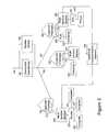
- FIG. 1illustrates an example power distribution system where the present invention may be employed
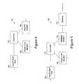
- FIG. 3shows an LV subnet in a PLCS according to an embodiment of the present invention
- FIG. 4is a diagram of a multi-function modem according to one embodiment of the present invention.
- a distribution transformer 140may function to distribute one, two, three, or more phase power signals to the customer premises 160 , depending upon the demands of the user. In the United States, for example, these local distribution transformers typically feed anywhere from one to ten homes, depending upon the concentration of the customer premises in a particular area. Distribution transformers 140 may be pole-top transformers located on a utility pole, pad-mounted transformers located on the ground, or transformers located under ground level. As is known to those skilled in the art, distribution transformers in overhead power lines tap off power from the MV power lines and are in parallel with the MV power line conductors. In contrast, in most URD systems the distribution transformer is in series with the MV conductor. Specifically, in a URD system a first MV cable and a second MV cable plug into the distribution transformer and are connected together by a conductor inside the transformer housing that is also connected to one end of the transformer's primary winding.
- data floworiginates from a user device, which provides the data to a power line modem (PLM) 200 , which is well-known in the art.
- PLMpower line modem
- Various electrical circuits 210 within the customer's premises 160distribute power and data signals within the customer premises 160 .
- the customerdraws power on demand by plugging a device into a power outlet.
- the customermay plug the PLM 200 into a power outlet to digitally connect user devices to communicate data signals carried by the power wiring.
- the PLM 200thus serves as an interface for user devices to access the PLCS.
- the PLM 200may have a variety of interfaces for customer data appliances.
- a PLM 200may include a RJ-11 Plain Old Telephone Service (POTS) connector, an RS-232 connector, a USB connector, a 10 Base-T connector, RJ-45 connector, and the like.
- POTSPlain Old Telephone Service
- RS-232 connectorRS-232 connector
- USB connectora USB connector
- 10 Base-T connectora 10 Base-T connector
- RJ-45 connectora 10 Base-T connector
- a customermay connect a variety of user devices to the PLCS.
- multiple PLMs 200may be plugged into power outlets throughout the customer premises 160 , with each PLM 200 communicating over the same wiring 210 internal to the customer premises 160 .
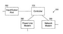
- the multi-function modem 250may include a DSL modem and cable modem (instead of a power line modem 280 and a network modem 290 ).
- This examplemay allow for the same functionality as described above where, for example, both modems may be used to transmit data, or one modem may provide a backup capability to the other modem.
- one input/output portmay be a category 5 type Ethernet port and the second input/output port may be a coaxial cable port.
- the input/output portsmay be other types of ports as well.
- Such a multi-function modem 250may be used, for example, in a user premises that has both Ethernet and coaxial cable installed.
- the multi-function modem 250may transmit the data signal from the power line modem 280 along both cables allowing more of the premises to be served with a network connection. Alternately, data to the two input/output ports may be routed as well.
- video data received via either the PLM 280may be routed to the first input/output port (e.g., a coaxial cable port) and VoIP data may be routed to the second input/output port (e.g., to a VoIP telephone).
- first input/output porte.g., a coaxial cable port
- VoIP datamay be routed to the second input/output port (e.g., to a VoIP telephone).
- the controllermay determine where to route data from the first and second input/output ports 260 , 300 (e.g., based on destination, packet size, type of packet, network availability, communication rates, and/or latency, etc.).
- the controller 270may also dedicate the data received from the power line modem 280 to one input/output port and the data received from the network modem to the other input/output port.
Landscapes
- Engineering & Computer Science (AREA)
- Computer Networks & Wireless Communication (AREA)
- Signal Processing (AREA)
- Cable Transmission Systems, Equalization Of Radio And Reduction Of Echo (AREA)
- Small-Scale Networks (AREA)
Abstract
Description
Claims (39)
Priority Applications (1)
| Application Number | Priority Date | Filing Date | Title |
|---|---|---|---|
| US11/097,286US7856032B2 (en) | 2005-04-04 | 2005-04-04 | Multi-function modem device |
Applications Claiming Priority (1)
| Application Number | Priority Date | Filing Date | Title |
|---|---|---|---|
| US11/097,286US7856032B2 (en) | 2005-04-04 | 2005-04-04 | Multi-function modem device |
Publications (2)
| Publication Number | Publication Date |
|---|---|
| US20060221995A1 US20060221995A1 (en) | 2006-10-05 |
| US7856032B2true US7856032B2 (en) | 2010-12-21 |
Family
ID=37070395
Family Applications (1)
| Application Number | Title | Priority Date | Filing Date |
|---|---|---|---|
| US11/097,286Expired - Fee RelatedUS7856032B2 (en) | 2005-04-04 | 2005-04-04 | Multi-function modem device |
Country Status (1)
| Country | Link |
|---|---|
| US (1) | US7856032B2 (en) |
Cited By (4)
| Publication number | Priority date | Publication date | Assignee | Title |
|---|---|---|---|---|
| US20090252208A1 (en)* | 2005-03-29 | 2009-10-08 | Frye Jr Bernard F | Multi-Unit Power Line Communications System and Method |
| US20130128724A1 (en)* | 2011-11-22 | 2013-05-23 | Total Walther Gmbh, Feuerschutz Und Sicherheit | System and method for backup communication using power over ethernet |
| US8520696B1 (en)* | 2010-07-30 | 2013-08-27 | Qualcomm Incorporated | Terminal selection diversity for powerline communications |
| US9130658B2 (en) | 2013-05-06 | 2015-09-08 | Qualcomm Incorporated | Selection diversity in a powerline communication system |
Families Citing this family (134)
| Publication number | Priority date | Publication date | Assignee | Title |
|---|---|---|---|---|
| US7321291B2 (en)* | 2004-10-26 | 2008-01-22 | Current Technologies, Llc | Power line communications system and method of operating the same |
| US7265664B2 (en) | 2005-04-04 | 2007-09-04 | Current Technologies, Llc | Power line communications system and method |
| US7259657B2 (en)* | 2005-06-21 | 2007-08-21 | Current Technologies, Llc | Multi-subnet power line communications system and method |
| US20080279199A1 (en)* | 2005-11-29 | 2008-11-13 | Dong Young Park | Power Line Communication System and Communication Device Used in the System |
| US20080012724A1 (en) | 2006-01-30 | 2008-01-17 | Corcoran Kevin F | Power line communications module and method |
| US7852207B2 (en)* | 2006-02-14 | 2010-12-14 | Current Technologies, Llc | Method for establishing power line communication link |
| US7796025B2 (en) | 2006-03-27 | 2010-09-14 | Current Technologies, Llc | Power line communication device and method |
| US7764943B2 (en)* | 2006-03-27 | 2010-07-27 | Current Technologies, Llc | Overhead and underground power line communication system and method using a bypass |
| US8554943B1 (en)* | 2006-03-31 | 2013-10-08 | Emc Corporation | Method and system for reducing packet latency in networks with both low latency and high bandwidths requirements |
| US7859646B2 (en)* | 2007-01-24 | 2010-12-28 | Adelphi University | Interferometric method for improving the resolution of a lithographic system |
| US20110019662A1 (en) | 2007-06-28 | 2011-01-27 | Rebelvox Llc | Method for downloading and using a communication application through a web browser |
| US11095583B2 (en) | 2007-06-28 | 2021-08-17 | Voxer Ip Llc | Real-time messaging method and apparatus |
| US9178916B2 (en) | 2007-06-28 | 2015-11-03 | Voxer Ip Llc | Real-time messaging method and apparatus |
| US8180029B2 (en) | 2007-06-28 | 2012-05-15 | Voxer Ip Llc | Telecommunication and multimedia management method and apparatus |
| US20090296703A1 (en)* | 2008-05-30 | 2009-12-03 | Ruby Tech Corp. | Method and system for dynamic roaming across wireless networks |
| JP2011211435A (en)* | 2010-03-29 | 2011-10-20 | Kyocera Corp | Communication repeater |
| US9270747B2 (en)* | 2011-04-08 | 2016-02-23 | Kaseya Limited | Method and apparatus of performing peer-to-peer communication establishment and connection change-over |
| US8711687B2 (en)* | 2011-11-22 | 2014-04-29 | Tyco Fire & Security Gmbh | System and method for backup communication over ethernet |
| US9999038B2 (en) | 2013-05-31 | 2018-06-12 | At&T Intellectual Property I, L.P. | Remote distributed antenna system |
| US9525524B2 (en) | 2013-05-31 | 2016-12-20 | At&T Intellectual Property I, L.P. | Remote distributed antenna system |
| US8897697B1 (en) | 2013-11-06 | 2014-11-25 | At&T Intellectual Property I, Lp | Millimeter-wave surface-wave communications |
| US9768833B2 (en) | 2014-09-15 | 2017-09-19 | At&T Intellectual Property I, L.P. | Method and apparatus for sensing a condition in a transmission medium of electromagnetic waves |
| US10063280B2 (en) | 2014-09-17 | 2018-08-28 | At&T Intellectual Property I, L.P. | Monitoring and mitigating conditions in a communication network |
| US9615269B2 (en) | 2014-10-02 | 2017-04-04 | At&T Intellectual Property I, L.P. | Method and apparatus that provides fault tolerance in a communication network |
| US9685992B2 (en) | 2014-10-03 | 2017-06-20 | At&T Intellectual Property I, L.P. | Circuit panel network and methods thereof |
| US9503189B2 (en) | 2014-10-10 | 2016-11-22 | At&T Intellectual Property I, L.P. | Method and apparatus for arranging communication sessions in a communication system |
| US9973299B2 (en) | 2014-10-14 | 2018-05-15 | At&T Intellectual Property I, L.P. | Method and apparatus for adjusting a mode of communication in a communication network |
| US9627768B2 (en) | 2014-10-21 | 2017-04-18 | At&T Intellectual Property I, L.P. | Guided-wave transmission device with non-fundamental mode propagation and methods for use therewith |
| US9577306B2 (en) | 2014-10-21 | 2017-02-21 | At&T Intellectual Property I, L.P. | Guided-wave transmission device and methods for use therewith |
| US9769020B2 (en) | 2014-10-21 | 2017-09-19 | At&T Intellectual Property I, L.P. | Method and apparatus for responding to events affecting communications in a communication network |
| US9312919B1 (en) | 2014-10-21 | 2016-04-12 | At&T Intellectual Property I, Lp | Transmission device with impairment compensation and methods for use therewith |
| US9780834B2 (en) | 2014-10-21 | 2017-10-03 | At&T Intellectual Property I, L.P. | Method and apparatus for transmitting electromagnetic waves |
| US9653770B2 (en) | 2014-10-21 | 2017-05-16 | At&T Intellectual Property I, L.P. | Guided wave coupler, coupling module and methods for use therewith |
| US9800327B2 (en) | 2014-11-20 | 2017-10-24 | At&T Intellectual Property I, L.P. | Apparatus for controlling operations of a communication device and methods thereof |
| US9544006B2 (en) | 2014-11-20 | 2017-01-10 | At&T Intellectual Property I, L.P. | Transmission device with mode division multiplexing and methods for use therewith |
| US10009067B2 (en) | 2014-12-04 | 2018-06-26 | At&T Intellectual Property I, L.P. | Method and apparatus for configuring a communication interface |
| US9997819B2 (en) | 2015-06-09 | 2018-06-12 | At&T Intellectual Property I, L.P. | Transmission medium and method for facilitating propagation of electromagnetic waves via a core |
| US10243784B2 (en) | 2014-11-20 | 2019-03-26 | At&T Intellectual Property I, L.P. | System for generating topology information and methods thereof |
| US9742462B2 (en) | 2014-12-04 | 2017-08-22 | At&T Intellectual Property I, L.P. | Transmission medium and communication interfaces and methods for use therewith |
| US9461706B1 (en) | 2015-07-31 | 2016-10-04 | At&T Intellectual Property I, Lp | Method and apparatus for exchanging communication signals |
| US9954287B2 (en) | 2014-11-20 | 2018-04-24 | At&T Intellectual Property I, L.P. | Apparatus for converting wireless signals and electromagnetic waves and methods thereof |
| US9876570B2 (en) | 2015-02-20 | 2018-01-23 | At&T Intellectual Property I, Lp | Guided-wave transmission device with non-fundamental mode propagation and methods for use therewith |
| US9749013B2 (en) | 2015-03-17 | 2017-08-29 | At&T Intellectual Property I, L.P. | Method and apparatus for reducing attenuation of electromagnetic waves guided by a transmission medium |
| US10224981B2 (en) | 2015-04-24 | 2019-03-05 | At&T Intellectual Property I, Lp | Passive electrical coupling device and methods for use therewith |
| US9705561B2 (en) | 2015-04-24 | 2017-07-11 | At&T Intellectual Property I, L.P. | Directional coupling device and methods for use therewith |
| US9793954B2 (en) | 2015-04-28 | 2017-10-17 | At&T Intellectual Property I, L.P. | Magnetic coupling device and methods for use therewith |
| US9748626B2 (en) | 2015-05-14 | 2017-08-29 | At&T Intellectual Property I, L.P. | Plurality of cables having different cross-sectional shapes which are bundled together to form a transmission medium |
| US9871282B2 (en) | 2015-05-14 | 2018-01-16 | At&T Intellectual Property I, L.P. | At least one transmission medium having a dielectric surface that is covered at least in part by a second dielectric |
| US9490869B1 (en) | 2015-05-14 | 2016-11-08 | At&T Intellectual Property I, L.P. | Transmission medium having multiple cores and methods for use therewith |
| US10650940B2 (en) | 2015-05-15 | 2020-05-12 | At&T Intellectual Property I, L.P. | Transmission medium having a conductive material and methods for use therewith |
| US9917341B2 (en) | 2015-05-27 | 2018-03-13 | At&T Intellectual Property I, L.P. | Apparatus and method for launching electromagnetic waves and for modifying radial dimensions of the propagating electromagnetic waves |
| US10348391B2 (en) | 2015-06-03 | 2019-07-09 | At&T Intellectual Property I, L.P. | Client node device with frequency conversion and methods for use therewith |
| US10756805B2 (en) | 2015-06-03 | 2020-08-25 | At&T Intellectual Property I, L.P. | Client node device with frequency conversion and methods for use therewith |
| US9912381B2 (en) | 2015-06-03 | 2018-03-06 | At&T Intellectual Property I, Lp | Network termination and methods for use therewith |
| US10812174B2 (en) | 2015-06-03 | 2020-10-20 | At&T Intellectual Property I, L.P. | Client node device and methods for use therewith |
| US9866309B2 (en) | 2015-06-03 | 2018-01-09 | At&T Intellectual Property I, Lp | Host node device and methods for use therewith |
| US9913139B2 (en) | 2015-06-09 | 2018-03-06 | At&T Intellectual Property I, L.P. | Signal fingerprinting for authentication of communicating devices |
| US9820146B2 (en) | 2015-06-12 | 2017-11-14 | At&T Intellectual Property I, L.P. | Method and apparatus for authentication and identity management of communicating devices |
| US9865911B2 (en) | 2015-06-25 | 2018-01-09 | At&T Intellectual Property I, L.P. | Waveguide system for slot radiating first electromagnetic waves that are combined into a non-fundamental wave mode second electromagnetic wave on a transmission medium |
| US9640850B2 (en) | 2015-06-25 | 2017-05-02 | At&T Intellectual Property I, L.P. | Methods and apparatus for inducing a non-fundamental wave mode on a transmission medium |
| US9509415B1 (en) | 2015-06-25 | 2016-11-29 | At&T Intellectual Property I, L.P. | Methods and apparatus for inducing a fundamental wave mode on a transmission medium |
| US9853342B2 (en) | 2015-07-14 | 2017-12-26 | At&T Intellectual Property I, L.P. | Dielectric transmission medium connector and methods for use therewith |
| US10044409B2 (en) | 2015-07-14 | 2018-08-07 | At&T Intellectual Property I, L.P. | Transmission medium and methods for use therewith |
| US10148016B2 (en) | 2015-07-14 | 2018-12-04 | At&T Intellectual Property I, L.P. | Apparatus and methods for communicating utilizing an antenna array |
| US10205655B2 (en) | 2015-07-14 | 2019-02-12 | At&T Intellectual Property I, L.P. | Apparatus and methods for communicating utilizing an antenna array and multiple communication paths |
| US9628116B2 (en) | 2015-07-14 | 2017-04-18 | At&T Intellectual Property I, L.P. | Apparatus and methods for transmitting wireless signals |
| US9882257B2 (en) | 2015-07-14 | 2018-01-30 | At&T Intellectual Property I, L.P. | Method and apparatus for launching a wave mode that mitigates interference |
| US9847566B2 (en) | 2015-07-14 | 2017-12-19 | At&T Intellectual Property I, L.P. | Method and apparatus for adjusting a field of a signal to mitigate interference |
| US10090606B2 (en) | 2015-07-15 | 2018-10-02 | At&T Intellectual Property I, L.P. | Antenna system with dielectric array and methods for use therewith |
| US9749053B2 (en) | 2015-07-23 | 2017-08-29 | At&T Intellectual Property I, L.P. | Node device, repeater and methods for use therewith |
| US9948333B2 (en) | 2015-07-23 | 2018-04-17 | At&T Intellectual Property I, L.P. | Method and apparatus for wireless communications to mitigate interference |
| US9871283B2 (en) | 2015-07-23 | 2018-01-16 | At&T Intellectual Property I, Lp | Transmission medium having a dielectric core comprised of plural members connected by a ball and socket configuration |
| US9912027B2 (en) | 2015-07-23 | 2018-03-06 | At&T Intellectual Property I, L.P. | Method and apparatus for exchanging communication signals |
| US9735833B2 (en) | 2015-07-31 | 2017-08-15 | At&T Intellectual Property I, L.P. | Method and apparatus for communications management in a neighborhood network |
| US9967173B2 (en) | 2015-07-31 | 2018-05-08 | At&T Intellectual Property I, L.P. | Method and apparatus for authentication and identity management of communicating devices |
| US9904535B2 (en) | 2015-09-14 | 2018-02-27 | At&T Intellectual Property I, L.P. | Method and apparatus for distributing software |
| US9769128B2 (en) | 2015-09-28 | 2017-09-19 | At&T Intellectual Property I, L.P. | Method and apparatus for encryption of communications over a network |
| US9729197B2 (en) | 2015-10-01 | 2017-08-08 | At&T Intellectual Property I, L.P. | Method and apparatus for communicating network management traffic over a network |
| US9876264B2 (en) | 2015-10-02 | 2018-01-23 | At&T Intellectual Property I, Lp | Communication system, guided wave switch and methods for use therewith |
| US10355367B2 (en) | 2015-10-16 | 2019-07-16 | At&T Intellectual Property I, L.P. | Antenna structure for exchanging wireless signals |
| ITUA20163024A1 (en)* | 2016-04-29 | 2017-10-29 | St Microelectronics Srl | SEMICONDUCTOR DEVICE AND CORRESPONDING DEBUGGING PROCEDURE |
| US9860075B1 (en) | 2016-08-26 | 2018-01-02 | At&T Intellectual Property I, L.P. | Method and communication node for broadband distribution |
| US10811767B2 (en) | 2016-10-21 | 2020-10-20 | At&T Intellectual Property I, L.P. | System and dielectric antenna with convex dielectric radome |
| US10312567B2 (en) | 2016-10-26 | 2019-06-04 | At&T Intellectual Property I, L.P. | Launcher with planar strip antenna and methods for use therewith |
| US10225025B2 (en) | 2016-11-03 | 2019-03-05 | At&T Intellectual Property I, L.P. | Method and apparatus for detecting a fault in a communication system |
| US10498044B2 (en) | 2016-11-03 | 2019-12-03 | At&T Intellectual Property I, L.P. | Apparatus for configuring a surface of an antenna |
| US10291334B2 (en) | 2016-11-03 | 2019-05-14 | At&T Intellectual Property I, L.P. | System for detecting a fault in a communication system |
| US10224634B2 (en) | 2016-11-03 | 2019-03-05 | At&T Intellectual Property I, L.P. | Methods and apparatus for adjusting an operational characteristic of an antenna |
| US10340603B2 (en) | 2016-11-23 | 2019-07-02 | At&T Intellectual Property I, L.P. | Antenna system having shielded structural configurations for assembly |
| US10535928B2 (en) | 2016-11-23 | 2020-01-14 | At&T Intellectual Property I, L.P. | Antenna system and methods for use therewith |
| US10090594B2 (en) | 2016-11-23 | 2018-10-02 | At&T Intellectual Property I, L.P. | Antenna system having structural configurations for assembly |
| US10178445B2 (en) | 2016-11-23 | 2019-01-08 | At&T Intellectual Property I, L.P. | Methods, devices, and systems for load balancing between a plurality of waveguides |
| US10340601B2 (en) | 2016-11-23 | 2019-07-02 | At&T Intellectual Property I, L.P. | Multi-antenna system and methods for use therewith |
| US10361489B2 (en) | 2016-12-01 | 2019-07-23 | At&T Intellectual Property I, L.P. | Dielectric dish antenna system and methods for use therewith |
| US10305190B2 (en) | 2016-12-01 | 2019-05-28 | At&T Intellectual Property I, L.P. | Reflecting dielectric antenna system and methods for use therewith |
| US10637149B2 (en) | 2016-12-06 | 2020-04-28 | At&T Intellectual Property I, L.P. | Injection molded dielectric antenna and methods for use therewith |
| US10439675B2 (en) | 2016-12-06 | 2019-10-08 | At&T Intellectual Property I, L.P. | Method and apparatus for repeating guided wave communication signals |
| US10382976B2 (en) | 2016-12-06 | 2019-08-13 | At&T Intellectual Property I, L.P. | Method and apparatus for managing wireless communications based on communication paths and network device positions |
| US10727599B2 (en) | 2016-12-06 | 2020-07-28 | At&T Intellectual Property I, L.P. | Launcher with slot antenna and methods for use therewith |
| US10326494B2 (en) | 2016-12-06 | 2019-06-18 | At&T Intellectual Property I, L.P. | Apparatus for measurement de-embedding and methods for use therewith |
| US10020844B2 (en) | 2016-12-06 | 2018-07-10 | T&T Intellectual Property I, L.P. | Method and apparatus for broadcast communication via guided waves |
| US10694379B2 (en) | 2016-12-06 | 2020-06-23 | At&T Intellectual Property I, L.P. | Waveguide system with device-based authentication and methods for use therewith |
| US9927517B1 (en) | 2016-12-06 | 2018-03-27 | At&T Intellectual Property I, L.P. | Apparatus and methods for sensing rainfall |
| US10135145B2 (en) | 2016-12-06 | 2018-11-20 | At&T Intellectual Property I, L.P. | Apparatus and methods for generating an electromagnetic wave along a transmission medium |
| US10755542B2 (en) | 2016-12-06 | 2020-08-25 | At&T Intellectual Property I, L.P. | Method and apparatus for surveillance via guided wave communication |
| US10819035B2 (en) | 2016-12-06 | 2020-10-27 | At&T Intellectual Property I, L.P. | Launcher with helical antenna and methods for use therewith |
| US10243270B2 (en) | 2016-12-07 | 2019-03-26 | At&T Intellectual Property I, L.P. | Beam adaptive multi-feed dielectric antenna system and methods for use therewith |
| US10547348B2 (en) | 2016-12-07 | 2020-01-28 | At&T Intellectual Property I, L.P. | Method and apparatus for switching transmission mediums in a communication system |
| US10446936B2 (en) | 2016-12-07 | 2019-10-15 | At&T Intellectual Property I, L.P. | Multi-feed dielectric antenna system and methods for use therewith |
| US10168695B2 (en) | 2016-12-07 | 2019-01-01 | At&T Intellectual Property I, L.P. | Method and apparatus for controlling an unmanned aircraft |
| US10139820B2 (en) | 2016-12-07 | 2018-11-27 | At&T Intellectual Property I, L.P. | Method and apparatus for deploying equipment of a communication system |
| US10027397B2 (en) | 2016-12-07 | 2018-07-17 | At&T Intellectual Property I, L.P. | Distributed antenna system and methods for use therewith |
| US10389029B2 (en) | 2016-12-07 | 2019-08-20 | At&T Intellectual Property I, L.P. | Multi-feed dielectric antenna system with core selection and methods for use therewith |
| US10359749B2 (en) | 2016-12-07 | 2019-07-23 | At&T Intellectual Property I, L.P. | Method and apparatus for utilities management via guided wave communication |
| US9893795B1 (en) | 2016-12-07 | 2018-02-13 | At&T Intellectual Property I, Lp | Method and repeater for broadband distribution |
| US10530505B2 (en) | 2016-12-08 | 2020-01-07 | At&T Intellectual Property I, L.P. | Apparatus and methods for launching electromagnetic waves along a transmission medium |
| US10103422B2 (en) | 2016-12-08 | 2018-10-16 | At&T Intellectual Property I, L.P. | Method and apparatus for mounting network devices |
| US10938108B2 (en) | 2016-12-08 | 2021-03-02 | At&T Intellectual Property I, L.P. | Frequency selective multi-feed dielectric antenna system and methods for use therewith |
| US10777873B2 (en) | 2016-12-08 | 2020-09-15 | At&T Intellectual Property I, L.P. | Method and apparatus for mounting network devices |
| US10389037B2 (en) | 2016-12-08 | 2019-08-20 | At&T Intellectual Property I, L.P. | Apparatus and methods for selecting sections of an antenna array and use therewith |
| US10411356B2 (en) | 2016-12-08 | 2019-09-10 | At&T Intellectual Property I, L.P. | Apparatus and methods for selectively targeting communication devices with an antenna array |
| US10069535B2 (en) | 2016-12-08 | 2018-09-04 | At&T Intellectual Property I, L.P. | Apparatus and methods for launching electromagnetic waves having a certain electric field structure |
| US9911020B1 (en) | 2016-12-08 | 2018-03-06 | At&T Intellectual Property I, L.P. | Method and apparatus for tracking via a radio frequency identification device |
| US10601494B2 (en) | 2016-12-08 | 2020-03-24 | At&T Intellectual Property I, L.P. | Dual-band communication device and method for use therewith |
| US9998870B1 (en) | 2016-12-08 | 2018-06-12 | At&T Intellectual Property I, L.P. | Method and apparatus for proximity sensing |
| US10916969B2 (en) | 2016-12-08 | 2021-02-09 | At&T Intellectual Property I, L.P. | Method and apparatus for providing power using an inductive coupling |
| US10326689B2 (en) | 2016-12-08 | 2019-06-18 | At&T Intellectual Property I, L.P. | Method and system for providing alternative communication paths |
| US10264586B2 (en) | 2016-12-09 | 2019-04-16 | At&T Mobility Ii Llc | Cloud-based packet controller and methods for use therewith |
| US10340983B2 (en) | 2016-12-09 | 2019-07-02 | At&T Intellectual Property I, L.P. | Method and apparatus for surveying remote sites via guided wave communications |
| US9838896B1 (en) | 2016-12-09 | 2017-12-05 | At&T Intellectual Property I, L.P. | Method and apparatus for assessing network coverage |
| US9973940B1 (en) | 2017-02-27 | 2018-05-15 | At&T Intellectual Property I, L.P. | Apparatus and methods for dynamic impedance matching of a guided wave launcher |
| US10298293B2 (en) | 2017-03-13 | 2019-05-21 | At&T Intellectual Property I, L.P. | Apparatus of communication utilizing wireless network devices |
| WO2020062268A1 (en)* | 2018-09-30 | 2020-04-02 | 华为技术有限公司 | Method and device for load balancing and message reordering in network |
| US12063078B2 (en)* | 2022-02-19 | 2024-08-13 | Charter Communications Operating, Llc | Docsis radio frequency (RF) leakage management |
Citations (114)
| Publication number | Priority date | Publication date | Assignee | Title |
|---|---|---|---|---|
| US3369078A (en) | 1965-06-28 | 1968-02-13 | Charles R. Stradley | System for transmitting stereophonic signals over electric power lines |
| US3810096A (en) | 1972-09-14 | 1974-05-07 | Integrated Syst Co | Method and system for transmitting data and indicating room status |
| US3911415A (en) | 1973-12-18 | 1975-10-07 | Westinghouse Electric Corp | Distribution network power line carrier communication system |
| US3942170A (en) | 1975-01-31 | 1976-03-02 | Westinghouse Electric Corporation | Distribution network powerline carrier communication system |
| US3942168A (en) | 1975-01-31 | 1976-03-02 | Westinghouse Electric Corporation | Distribution network power line communication system |
| US3944723A (en) | 1974-12-05 | 1976-03-16 | General Electric Company | Station for power line access data system |
| US3964048A (en) | 1974-01-28 | 1976-06-15 | General Public Utilities Corporation | Communicating over power network within a building or other user location |
| US3967264A (en) | 1975-01-31 | 1976-06-29 | Westinghouse Electric Corporation | Distribution network power line communication system including addressable interrogation and response repeater |
| US3973240A (en) | 1974-12-05 | 1976-08-03 | General Electric Company | Power line access data system |
| US3973087A (en) | 1974-12-05 | 1976-08-03 | General Electric Company | Signal repeater for power line access data system |
| US4004110A (en) | 1975-10-07 | 1977-01-18 | Westinghouse Electric Corporation | Power supply for power line carrier communication systems |
| US4057793A (en) | 1975-10-28 | 1977-11-08 | Johnson Raymond E | Current carrier communication system |
| US4060735A (en) | 1976-07-12 | 1977-11-29 | Johnson Controls, Inc. | Control system employing a programmable multiple channel controller for transmitting control signals over electrical power lines |
| US4239940A (en) | 1978-12-26 | 1980-12-16 | Bertrand Dorfman | Carrier current communications system |
| US4250489A (en) | 1978-10-31 | 1981-02-10 | Westinghouse Electric Corp. | Distribution network communication system having branch connected repeaters |
| US4475209A (en) | 1982-04-23 | 1984-10-02 | Westinghouse Electric Corp. | Regenerator for an intrabundle power-line communication system |
| US4599598A (en) | 1981-09-14 | 1986-07-08 | Matsushita Electric Works, Ltd. | Data transmission system utilizing power line |
| US4638298A (en) | 1985-07-16 | 1987-01-20 | Telautograph Corporation | Communication system having message repeating terminals |
| US4642607A (en) | 1985-08-06 | 1987-02-10 | National Semiconductor Corporation | Power line carrier communications system transformer bridge |
| US5066939A (en) | 1989-10-04 | 1991-11-19 | Mansfield Jr Amos R | Method and means of operating a power line carrier communication system |
| US5257006A (en) | 1990-09-21 | 1993-10-26 | Echelon Corporation | Method and apparatus for power line communications |
| US5319634A (en) | 1991-10-07 | 1994-06-07 | Phoenix Corporation | Multiple access telephone extension systems and methods |
| GB2293950A (en) | 1994-10-04 | 1996-04-10 | Northern Telecom Ltd | Communications system using power distribution network |
| US5726980A (en) | 1995-03-30 | 1998-03-10 | Northern Telecom Limited | Time division duplex communications repeater |
| US5818821A (en) | 1994-12-30 | 1998-10-06 | Intelogis, Inc. | Universal lan power line carrier repeater system and method |
| US5870016A (en) | 1997-02-03 | 1999-02-09 | Eva Cogenics Inc Euaday Division | Power line carrier data transmission systems having signal conditioning for the carrier data signal |
| US5929748A (en) | 1997-06-12 | 1999-07-27 | Microsoft Corporation | Automated home control using existing electrical lines as a communications medium |
| US5949327A (en) | 1994-08-26 | 1999-09-07 | Norweb Plc | Coupling of telecommunications signals to a balanced power distribution network |
| US5978371A (en) | 1997-03-31 | 1999-11-02 | Abb Power T&D Company Inc. | Communications module base repeater |
| US6151480A (en) | 1997-06-27 | 2000-11-21 | Adc Telecommunications, Inc. | System and method for distributing RF signals over power lines within a substantially closed environment |
| US6160795A (en) | 1997-03-21 | 2000-12-12 | Siemens Aktiengesellschaft | Network communication |
| US6346875B1 (en) | 2000-01-03 | 2002-02-12 | General Electric Company | GHM aggregator |
| US6373377B1 (en) | 2000-10-05 | 2002-04-16 | Conexant Systems, Inc. | Power supply with digital data coupling for power-line networking |
| US6417762B1 (en) | 2001-03-30 | 2002-07-09 | Comcircuits | Power line communication system using anti-resonance isolation and virtual earth ground signaling |
| US20020109585A1 (en) | 2001-02-15 | 2002-08-15 | Sanderson Lelon Wayne | Apparatus, method and system for range extension of a data communication signal on a high voltage cable |
| EP1251646A2 (en) | 2001-04-04 | 2002-10-23 | Siemens Aktiengesellschaft | Method for halfduplex transmission of informations between communication devices with repeaters |
| US20020186699A1 (en) | 2001-06-08 | 2002-12-12 | Kwok Timothy Chung Hing | System and method for providing high-speed communications access over an electrical network |
| US6522650B1 (en) | 2000-08-04 | 2003-02-18 | Intellon Corporation | Multicast and broadcast transmission with partial ARQ |
| US6526581B1 (en) | 1999-08-03 | 2003-02-25 | Ucentric Holdings, Llc | Multi-service in-home network with an open interface |
| US20030050737A1 (en) | 2001-09-10 | 2003-03-13 | Robert Osann | Energy-smart home system |
| US20030052770A1 (en) | 1999-11-15 | 2003-03-20 | Mansfield Amos R. | Fire system implemented with power line communications |
| US20030062990A1 (en) | 2001-08-30 | 2003-04-03 | Schaeffer Donald Joseph | Powerline bridge apparatus |
| US20030068033A1 (en)* | 2001-10-10 | 2003-04-10 | Kiko Frederick J. | Telecommunications gateway and method |
| US20030071719A1 (en) | 2001-10-02 | 2003-04-17 | Crenshaw Ralph E. | Method and apparatus for attaching power line communications to customer premises |
| US20030097452A1 (en)* | 2001-11-16 | 2003-05-22 | Samsung Electronics Co., Ltd. | Home network system |
| US20030100288A1 (en)* | 2001-11-29 | 2003-05-29 | General Electric Company One Research Circle | Universal PLC radio frequency enhanced bridge |
| US20030103307A1 (en) | 2000-04-19 | 2003-06-05 | Kauls Dostert | Method and device for conditioning electric installations in buildings for the rapid transmission of data |
| US20030106067A1 (en) | 2001-11-30 | 2003-06-05 | Hoskins Steve J. | Integrated internet protocol (IP) gateway services in an RF cable network |
| US6587739B1 (en) | 2000-09-29 | 2003-07-01 | Sunbeam Products, Inc. | Appliance communication and control system and appliances for use in same |
| US20030129978A1 (en)* | 2001-11-27 | 2003-07-10 | Sony Corporation | Communication system, communication terminal and communication method |
| US20030158677A1 (en)* | 2000-02-29 | 2003-08-21 | Swarztrauber Sayre A. | System and method for on-line monitoring and billing of power consumption |
| US6624532B1 (en) | 2001-05-18 | 2003-09-23 | Power Wan, Inc. | System and method for utility network load control |
| US20030184433A1 (en)* | 2000-08-14 | 2003-10-02 | Yeshayahu Zalitzky | Power line communication system |
| US20030224784A1 (en) | 2002-05-28 | 2003-12-04 | Amperion, Inc. | Communications system for providing broadband communications using a medium voltage cable of a power system |
| US20030226149A1 (en)* | 2002-05-31 | 2003-12-04 | Kyong-Joon Chun | Integrated home network system for providing multimedia services and integrated terminal device for the integrated home network system |
| US6687574B2 (en) | 2001-11-01 | 2004-02-03 | Telcordia Technologies, Inc. | System and method for surveying utility outages |
| US20040067745A1 (en) | 2002-10-02 | 2004-04-08 | Amperion, Inc. | Method and system for signal repeating in powerline communications |
| US20040066283A1 (en)* | 2002-01-08 | 2004-04-08 | Manis Constantine N. | Power line communications system combining high bitrate and low bitrate transmissions |
| US20040090312A1 (en) | 2001-10-27 | 2004-05-13 | Manis Constantine N. | Power line communication system with autonomous network segments |
| US20040110483A1 (en) | 2002-12-10 | 2004-06-10 | Mollenkopf James Douglas | Power line communication sytem and method |
| US20040135676A1 (en) | 2002-12-10 | 2004-07-15 | Berkman William H. | Power line communication system and method of operating the same |
| US6771775B1 (en) | 1998-08-17 | 2004-08-03 | Ascom Powerline Communications Ag | Arrangement for communicating messages via a low-voltage electricity supply system and adapter |
| US20040157551A1 (en) | 2002-06-21 | 2004-08-12 | Tantivy Communications, Inc | Repeater for extending range of time division duplex communication system |
| US6778817B1 (en) | 1998-12-01 | 2004-08-17 | Phonex Corporation | Method and system for combining wireless phone jack and RF wireless communications |
| US20040163128A1 (en) | 2003-01-31 | 2004-08-19 | Qwest Communications International Inc. | Fiber optic internet protocol network interface device and methods and systems for using the same |
| US20040168199A1 (en) | 2003-01-31 | 2004-08-26 | Qwest Communications International Inc. | DOCSIS network interface device and methods and systems for using the same |
| US20040178888A1 (en) | 2003-03-14 | 2004-09-16 | Coaxmedia, Inc. | Bi-directional transfer of signals between a power line communication system and a coaxial distribution system |
| US20040196144A1 (en) | 2001-10-02 | 2004-10-07 | Telkonet, Inc. | Method and apparatus for attaching power line communications to customer premises |
| US20040227623A1 (en) | 2003-05-07 | 2004-11-18 | Telkonet, Inc. | Network topology and packet routing method using low voltage power wiring |
| US20040233928A1 (en) | 2003-05-07 | 2004-11-25 | Telkonet, Inc. | Network topology and packet routing method using low voltage power wiring |
| US20040242185A1 (en) | 2003-05-29 | 2004-12-02 | Amperion, Inc. | Method and device for frequency translation in powerline communications |
| US6842459B1 (en) | 2000-04-19 | 2005-01-11 | Serconet Ltd. | Network combining wired and non-wired segments |
| US6844809B2 (en)* | 2001-12-04 | 2005-01-18 | Constantine N. Manis | Passive optical network backhaul for powerline communications |
| US20050015805A1 (en)* | 2003-07-17 | 2005-01-20 | Sony Corporation | Power line home network |
| US20050033534A1 (en) | 2003-08-08 | 2005-02-10 | Poweronedata Corporation | Automated utility metering system |
| US20050040809A1 (en) | 2003-08-22 | 2005-02-24 | Uber Arthur E. | Power line property measurement devices and power line fault location methods, devices and systems |
| US20050046550A1 (en) | 2001-10-02 | 2005-03-03 | Crenshaw Ralph E. | Method and apparatus for attaching power line communications to customer premises |
| US20050068223A1 (en) | 2002-01-09 | 2005-03-31 | Vavik Geir Monsen | Analogue regenerative transponders including regenerative transponder systems |
| US20050101312A1 (en)* | 2002-02-28 | 2005-05-12 | Kang Sung H. | Home network system |
| US20050129097A1 (en) | 2003-10-14 | 2005-06-16 | Strumpf David M. | Communication module and process for networking within and between powered communication devices over a multi-phase power distribution system or subsystem |
| US20050164666A1 (en) | 2002-10-02 | 2005-07-28 | Lang Jack A. | Communication methods and apparatus |
| US20050168326A1 (en) | 2002-12-10 | 2005-08-04 | Current Technologies, Llc | Power line repeater system and method |
| US20050200459A1 (en) | 2002-12-10 | 2005-09-15 | White Melvin J.Ii | Power line communication apparatus and method of using the same |
| US20050212688A1 (en)* | 2004-03-12 | 2005-09-29 | Xeline Co., Ltd. | Power line communication based supplemental service meter gateway and casing structure thereof, power line communication system and method using same |
| US6952159B1 (en) | 2000-05-30 | 2005-10-04 | Ascom Powerline Communications Ag | Coupling device |
| US20050220004A1 (en) | 2002-03-12 | 2005-10-06 | Koninklijke Philips Electronics N.V. | Repeater for power line communication system |
| US6956464B2 (en) | 2003-05-14 | 2005-10-18 | Abocom Systems, Inc. | Power apparatus having built-in powerline networking adapter |
| US6961303B1 (en) | 2000-09-21 | 2005-11-01 | Serconet Ltd. | Telephone communication system and method over local area network wiring |
| US20050249245A1 (en) | 2004-05-06 | 2005-11-10 | Serconet Ltd. | System and method for carrying a wireless based signal over wiring |
| US6977578B2 (en) | 2000-01-20 | 2005-12-20 | Current Technologies, Llc | Method of isolating data in a power line communications network |
| US6980091B2 (en) | 2002-12-10 | 2005-12-27 | Current Technologies, Llc | Power line communication system and method of operating the same |
| US20060002189A1 (en)* | 2004-06-30 | 2006-01-05 | Berkman William H | System and method for determining service availability and soliciting customers |
| US20060017324A1 (en) | 2004-07-21 | 2006-01-26 | Advanced Powerline Technologies, Inc. | Communications network using installed electrical power lines |
| US20060034330A1 (en) | 2003-03-17 | 2006-02-16 | Ryuichi Iwamura | Bandwidth management of virtual networks on a shared network |
| US20060038660A1 (en) | 2004-08-20 | 2006-02-23 | Tohru Doumuki | System and method for authenticating/registering network device in power line communication (PLC) |
| US20060044076A1 (en) | 2004-09-02 | 2006-03-02 | Law Robinson P S | Serial signal injection using capacitive and transformer couplings for power line communications |
| US20060045105A1 (en) | 2004-08-25 | 2006-03-02 | Dobosz Paul J | System and method for using a utility meter |
| US20060049693A1 (en) | 2004-09-08 | 2006-03-09 | Satius, Inc. | Apparatus and method for transmitting digital data over various communication media |
| US20060050642A1 (en)* | 2004-09-08 | 2006-03-09 | Visualgate Systems, Inc. | System, method and apparatus for adaptive video surveillance over power lines |
| US20060072695A1 (en) | 2004-10-04 | 2006-04-06 | Ryuichi Iwamura | System and method for synchronizing audio-visual devices on a power line communications (PLC) network |
| US20060073805A1 (en) | 2004-10-04 | 2006-04-06 | Markus Zumkeller | Dynamic FD coexistence method for PLC systems |
| US20060079230A1 (en)* | 2004-10-13 | 2006-04-13 | Russell Thomas C | System and methods for redundant networks |
| US20060077906A1 (en)* | 2003-09-29 | 2006-04-13 | The Kansai Electric Power Co., Inc. Matsushita Electric Works, Ltd | Path setting method, and network, relay station and parent station employing the path setting method |
| US20060097573A1 (en)* | 2004-10-26 | 2006-05-11 | Gidge Brett D | Power line communications system and method of operating the same |
| US20060140260A1 (en)* | 2003-03-03 | 2006-06-29 | Tdk Corporation | Power supply line communication modem and power supply line communication system |
| US20060165054A1 (en) | 2005-01-21 | 2006-07-27 | Ryuichi Iwamura | Power line network bridge |
| US20060251179A1 (en) | 2005-03-28 | 2006-11-09 | Akros Silicon, Inc. | Ethernet bridge |
| US20060291575A1 (en) | 2003-07-03 | 2006-12-28 | Berkman William H | Power Line Communication System and Method |
| US20070183447A1 (en) | 1998-07-28 | 2007-08-09 | Israeli Company Of Serconet Ltd. | Local area network of serial intelligent cells |
| US20070201494A1 (en) | 2002-06-07 | 2007-08-30 | Heng Lou | Last Leg Utility Grid High-Speed Data Communication Network Having Virtual Local Area Network Functionality |
| US7269403B1 (en)* | 2004-06-03 | 2007-09-11 | Miao George J | Dual-mode wireless and wired power line communications |
| US7308103B2 (en) | 2003-05-08 | 2007-12-11 | Current Technologies, Llc | Power line communication device and method of using the same |
| US20090040030A1 (en) | 2004-08-12 | 2009-02-12 | Mathews David K | Data Interface to the AC Power Line Via Standard Light Bulb Socket |
| US7554459B2 (en)* | 2003-07-17 | 2009-06-30 | Enel Distribuzione S.P.A. | Method and system for remote updates of meters for metering the consumption of electricity, water or gas |
Family Cites Families (1)
| Publication number | Priority date | Publication date | Assignee | Title |
|---|---|---|---|---|
| WO2002036583A1 (en)* | 2000-11-01 | 2002-05-10 | Shionogi & Co., Ltd. | Pgd2 receptor antagonistic pharmaceutical compositions |
- 2005
- 2005-04-04USUS11/097,286patent/US7856032B2/ennot_activeExpired - Fee Related
Patent Citations (128)
| Publication number | Priority date | Publication date | Assignee | Title |
|---|---|---|---|---|
| US3369078A (en) | 1965-06-28 | 1968-02-13 | Charles R. Stradley | System for transmitting stereophonic signals over electric power lines |
| US3810096A (en) | 1972-09-14 | 1974-05-07 | Integrated Syst Co | Method and system for transmitting data and indicating room status |
| US3911415A (en) | 1973-12-18 | 1975-10-07 | Westinghouse Electric Corp | Distribution network power line carrier communication system |
| US3964048A (en) | 1974-01-28 | 1976-06-15 | General Public Utilities Corporation | Communicating over power network within a building or other user location |
| US3944723A (en) | 1974-12-05 | 1976-03-16 | General Electric Company | Station for power line access data system |
| US3973240A (en) | 1974-12-05 | 1976-08-03 | General Electric Company | Power line access data system |
| US3973087A (en) | 1974-12-05 | 1976-08-03 | General Electric Company | Signal repeater for power line access data system |
| US3942170A (en) | 1975-01-31 | 1976-03-02 | Westinghouse Electric Corporation | Distribution network powerline carrier communication system |
| US3942168A (en) | 1975-01-31 | 1976-03-02 | Westinghouse Electric Corporation | Distribution network power line communication system |
| US3967264A (en) | 1975-01-31 | 1976-06-29 | Westinghouse Electric Corporation | Distribution network power line communication system including addressable interrogation and response repeater |
| US4004110A (en) | 1975-10-07 | 1977-01-18 | Westinghouse Electric Corporation | Power supply for power line carrier communication systems |
| US4057793A (en) | 1975-10-28 | 1977-11-08 | Johnson Raymond E | Current carrier communication system |
| US4060735A (en) | 1976-07-12 | 1977-11-29 | Johnson Controls, Inc. | Control system employing a programmable multiple channel controller for transmitting control signals over electrical power lines |
| US4250489A (en) | 1978-10-31 | 1981-02-10 | Westinghouse Electric Corp. | Distribution network communication system having branch connected repeaters |
| US4239940A (en) | 1978-12-26 | 1980-12-16 | Bertrand Dorfman | Carrier current communications system |
| US4599598A (en) | 1981-09-14 | 1986-07-08 | Matsushita Electric Works, Ltd. | Data transmission system utilizing power line |
| US4475209A (en) | 1982-04-23 | 1984-10-02 | Westinghouse Electric Corp. | Regenerator for an intrabundle power-line communication system |
| US4638298A (en) | 1985-07-16 | 1987-01-20 | Telautograph Corporation | Communication system having message repeating terminals |
| US4642607A (en) | 1985-08-06 | 1987-02-10 | National Semiconductor Corporation | Power line carrier communications system transformer bridge |
| US5066939A (en) | 1989-10-04 | 1991-11-19 | Mansfield Jr Amos R | Method and means of operating a power line carrier communication system |
| US5257006A (en) | 1990-09-21 | 1993-10-26 | Echelon Corporation | Method and apparatus for power line communications |
| US5319634A (en) | 1991-10-07 | 1994-06-07 | Phoenix Corporation | Multiple access telephone extension systems and methods |
| US5949327A (en) | 1994-08-26 | 1999-09-07 | Norweb Plc | Coupling of telecommunications signals to a balanced power distribution network |
| GB2293950A (en) | 1994-10-04 | 1996-04-10 | Northern Telecom Ltd | Communications system using power distribution network |
| US5818821A (en) | 1994-12-30 | 1998-10-06 | Intelogis, Inc. | Universal lan power line carrier repeater system and method |
| US5726980A (en) | 1995-03-30 | 1998-03-10 | Northern Telecom Limited | Time division duplex communications repeater |
| US5870016A (en) | 1997-02-03 | 1999-02-09 | Eva Cogenics Inc Euaday Division | Power line carrier data transmission systems having signal conditioning for the carrier data signal |
| US6160795A (en) | 1997-03-21 | 2000-12-12 | Siemens Aktiengesellschaft | Network communication |
| US5978371A (en) | 1997-03-31 | 1999-11-02 | Abb Power T&D Company Inc. | Communications module base repeater |
| US5929748A (en) | 1997-06-12 | 1999-07-27 | Microsoft Corporation | Automated home control using existing electrical lines as a communications medium |
| US6151480A (en) | 1997-06-27 | 2000-11-21 | Adc Telecommunications, Inc. | System and method for distributing RF signals over power lines within a substantially closed environment |
| US20070183447A1 (en) | 1998-07-28 | 2007-08-09 | Israeli Company Of Serconet Ltd. | Local area network of serial intelligent cells |
| US6771775B1 (en) | 1998-08-17 | 2004-08-03 | Ascom Powerline Communications Ag | Arrangement for communicating messages via a low-voltage electricity supply system and adapter |
| US6778817B1 (en) | 1998-12-01 | 2004-08-17 | Phonex Corporation | Method and system for combining wireless phone jack and RF wireless communications |
| US20030101459A1 (en)* | 1999-08-03 | 2003-05-29 | Ucentric Holdings, Llc | Multi-service in-home network with an open interface |
| US6526581B1 (en) | 1999-08-03 | 2003-02-25 | Ucentric Holdings, Llc | Multi-service in-home network with an open interface |
| US20050128057A1 (en) | 1999-11-15 | 2005-06-16 | Mansfield Amos R. | Preventing unintended communication among power line communication devices associated with different premises power distribution lines of an electric power distribution system |
| US20060132299A1 (en) | 1999-11-15 | 2006-06-22 | Ge Security, Inc. | Power line communication system with system member identification |
| US20030052770A1 (en) | 1999-11-15 | 2003-03-20 | Mansfield Amos R. | Fire system implemented with power line communications |
| US6346875B1 (en) | 2000-01-03 | 2002-02-12 | General Electric Company | GHM aggregator |
| US6977578B2 (en) | 2000-01-20 | 2005-12-20 | Current Technologies, Llc | Method of isolating data in a power line communications network |
| US20030158677A1 (en)* | 2000-02-29 | 2003-08-21 | Swarztrauber Sayre A. | System and method for on-line monitoring and billing of power consumption |
| US20050285720A1 (en) | 2000-04-14 | 2005-12-29 | Cope Leonard D | Power line communication apparatus and method of using the same |
| US6998962B2 (en) | 2000-04-14 | 2006-02-14 | Current Technologies, Llc | Power line communication apparatus and method of using the same |
| US6842459B1 (en) | 2000-04-19 | 2005-01-11 | Serconet Ltd. | Network combining wired and non-wired segments |
| US20030103307A1 (en) | 2000-04-19 | 2003-06-05 | Kauls Dostert | Method and device for conditioning electric installations in buildings for the rapid transmission of data |
| US6952159B1 (en) | 2000-05-30 | 2005-10-04 | Ascom Powerline Communications Ag | Coupling device |
| US6522650B1 (en) | 2000-08-04 | 2003-02-18 | Intellon Corporation | Multicast and broadcast transmission with partial ARQ |
| US20030184433A1 (en)* | 2000-08-14 | 2003-10-02 | Yeshayahu Zalitzky | Power line communication system |
| US6961303B1 (en) | 2000-09-21 | 2005-11-01 | Serconet Ltd. | Telephone communication system and method over local area network wiring |
| US6587739B1 (en) | 2000-09-29 | 2003-07-01 | Sunbeam Products, Inc. | Appliance communication and control system and appliances for use in same |
| US6373377B1 (en) | 2000-10-05 | 2002-04-16 | Conexant Systems, Inc. | Power supply with digital data coupling for power-line networking |
| US20020109585A1 (en) | 2001-02-15 | 2002-08-15 | Sanderson Lelon Wayne | Apparatus, method and system for range extension of a data communication signal on a high voltage cable |
| US20060079198A1 (en) | 2001-02-15 | 2006-04-13 | Sanderson Lelon W | Apparatus, method and system for range extension of a data communication signal on a high voltage cable |
| US6417762B1 (en) | 2001-03-30 | 2002-07-09 | Comcircuits | Power line communication system using anti-resonance isolation and virtual earth ground signaling |
| EP1251646A2 (en) | 2001-04-04 | 2002-10-23 | Siemens Aktiengesellschaft | Method for halfduplex transmission of informations between communication devices with repeaters |
| US6624532B1 (en) | 2001-05-18 | 2003-09-23 | Power Wan, Inc. | System and method for utility network load control |
| US20020186699A1 (en) | 2001-06-08 | 2002-12-12 | Kwok Timothy Chung Hing | System and method for providing high-speed communications access over an electrical network |
| US20030062990A1 (en) | 2001-08-30 | 2003-04-03 | Schaeffer Donald Joseph | Powerline bridge apparatus |
| US20030050737A1 (en) | 2001-09-10 | 2003-03-13 | Robert Osann | Energy-smart home system |
| US20030071719A1 (en) | 2001-10-02 | 2003-04-17 | Crenshaw Ralph E. | Method and apparatus for attaching power line communications to customer premises |
| US6975212B2 (en) | 2001-10-02 | 2005-12-13 | Telkonet Communications, Inc. | Method and apparatus for attaching power line communications to customer premises |
| US20050046550A1 (en) | 2001-10-02 | 2005-03-03 | Crenshaw Ralph E. | Method and apparatus for attaching power line communications to customer premises |
| US20040196144A1 (en) | 2001-10-02 | 2004-10-07 | Telkonet, Inc. | Method and apparatus for attaching power line communications to customer premises |
| US20030068033A1 (en)* | 2001-10-10 | 2003-04-10 | Kiko Frederick J. | Telecommunications gateway and method |
| US20040090312A1 (en) | 2001-10-27 | 2004-05-13 | Manis Constantine N. | Power line communication system with autonomous network segments |
| US6687574B2 (en) | 2001-11-01 | 2004-02-03 | Telcordia Technologies, Inc. | System and method for surveying utility outages |
| US20030097452A1 (en)* | 2001-11-16 | 2003-05-22 | Samsung Electronics Co., Ltd. | Home network system |
| US20030129978A1 (en)* | 2001-11-27 | 2003-07-10 | Sony Corporation | Communication system, communication terminal and communication method |
| US20030100288A1 (en)* | 2001-11-29 | 2003-05-29 | General Electric Company One Research Circle | Universal PLC radio frequency enhanced bridge |
| US20030106067A1 (en) | 2001-11-30 | 2003-06-05 | Hoskins Steve J. | Integrated internet protocol (IP) gateway services in an RF cable network |
| US6844809B2 (en)* | 2001-12-04 | 2005-01-18 | Constantine N. Manis | Passive optical network backhaul for powerline communications |
| US20040066283A1 (en)* | 2002-01-08 | 2004-04-08 | Manis Constantine N. | Power line communications system combining high bitrate and low bitrate transmissions |
| US20050068223A1 (en) | 2002-01-09 | 2005-03-31 | Vavik Geir Monsen | Analogue regenerative transponders including regenerative transponder systems |
| US20050101312A1 (en)* | 2002-02-28 | 2005-05-12 | Kang Sung H. | Home network system |
| US20050220004A1 (en) | 2002-03-12 | 2005-10-06 | Koninklijke Philips Electronics N.V. | Repeater for power line communication system |
| US6885674B2 (en) | 2002-05-28 | 2005-04-26 | Amperion, Inc. | Communications system for providing broadband communications using a medium voltage cable of a power system |
| US20030224784A1 (en) | 2002-05-28 | 2003-12-04 | Amperion, Inc. | Communications system for providing broadband communications using a medium voltage cable of a power system |
| US20030226149A1 (en)* | 2002-05-31 | 2003-12-04 | Kyong-Joon Chun | Integrated home network system for providing multimedia services and integrated terminal device for the integrated home network system |
| US20070201494A1 (en) | 2002-06-07 | 2007-08-30 | Heng Lou | Last Leg Utility Grid High-Speed Data Communication Network Having Virtual Local Area Network Functionality |
| US20040157551A1 (en) | 2002-06-21 | 2004-08-12 | Tantivy Communications, Inc | Repeater for extending range of time division duplex communication system |
| US20040067745A1 (en) | 2002-10-02 | 2004-04-08 | Amperion, Inc. | Method and system for signal repeating in powerline communications |
| US6993317B2 (en) | 2002-10-02 | 2006-01-31 | Amperion, Inc. | Method and system for signal repeating in powerline communications |
| US20050164666A1 (en) | 2002-10-02 | 2005-07-28 | Lang Jack A. | Communication methods and apparatus |
| US20040110483A1 (en) | 2002-12-10 | 2004-06-10 | Mollenkopf James Douglas | Power line communication sytem and method |
| US6965303B2 (en) | 2002-12-10 | 2005-11-15 | Current Technologies, Llc | Power line communication system and method |
| US6980091B2 (en) | 2002-12-10 | 2005-12-27 | Current Technologies, Llc | Power line communication system and method of operating the same |
| US20050168326A1 (en) | 2002-12-10 | 2005-08-04 | Current Technologies, Llc | Power line repeater system and method |
| US7224272B2 (en) | 2002-12-10 | 2007-05-29 | Current Technologies, Llc | Power line repeater system and method |
| US20050200459A1 (en) | 2002-12-10 | 2005-09-15 | White Melvin J.Ii | Power line communication apparatus and method of using the same |
| US20040135676A1 (en) | 2002-12-10 | 2004-07-15 | Berkman William H. | Power line communication system and method of operating the same |
| US20050273282A1 (en) | 2002-12-10 | 2005-12-08 | Mollenkopf James D | Power line communication system and method |
| US20040163128A1 (en) | 2003-01-31 | 2004-08-19 | Qwest Communications International Inc. | Fiber optic internet protocol network interface device and methods and systems for using the same |
| US20040168199A1 (en) | 2003-01-31 | 2004-08-26 | Qwest Communications International Inc. | DOCSIS network interface device and methods and systems for using the same |
| US20060140260A1 (en)* | 2003-03-03 | 2006-06-29 | Tdk Corporation | Power supply line communication modem and power supply line communication system |
| US20040178888A1 (en) | 2003-03-14 | 2004-09-16 | Coaxmedia, Inc. | Bi-directional transfer of signals between a power line communication system and a coaxial distribution system |
| US20060034330A1 (en) | 2003-03-17 | 2006-02-16 | Ryuichi Iwamura | Bandwidth management of virtual networks on a shared network |
| US20040233928A1 (en) | 2003-05-07 | 2004-11-25 | Telkonet, Inc. | Network topology and packet routing method using low voltage power wiring |
| US20040227623A1 (en) | 2003-05-07 | 2004-11-18 | Telkonet, Inc. | Network topology and packet routing method using low voltage power wiring |
| US7308103B2 (en) | 2003-05-08 | 2007-12-11 | Current Technologies, Llc | Power line communication device and method of using the same |
| US20080037784A1 (en) | 2003-05-08 | 2008-02-14 | Corcoran Kevin F | Power Line Communication Device and Method Of Using The Same |
| US6956464B2 (en) | 2003-05-14 | 2005-10-18 | Abocom Systems, Inc. | Power apparatus having built-in powerline networking adapter |
| US20040242185A1 (en) | 2003-05-29 | 2004-12-02 | Amperion, Inc. | Method and device for frequency translation in powerline communications |
| US20060291575A1 (en) | 2003-07-03 | 2006-12-28 | Berkman William H | Power Line Communication System and Method |
| US7554459B2 (en)* | 2003-07-17 | 2009-06-30 | Enel Distribuzione S.P.A. | Method and system for remote updates of meters for metering the consumption of electricity, water or gas |
| US20050015805A1 (en)* | 2003-07-17 | 2005-01-20 | Sony Corporation | Power line home network |
| US20050033534A1 (en) | 2003-08-08 | 2005-02-10 | Poweronedata Corporation | Automated utility metering system |
| US20050040809A1 (en) | 2003-08-22 | 2005-02-24 | Uber Arthur E. | Power line property measurement devices and power line fault location methods, devices and systems |
| US20060077906A1 (en)* | 2003-09-29 | 2006-04-13 | The Kansai Electric Power Co., Inc. Matsushita Electric Works, Ltd | Path setting method, and network, relay station and parent station employing the path setting method |
| US20050129097A1 (en) | 2003-10-14 | 2005-06-16 | Strumpf David M. | Communication module and process for networking within and between powered communication devices over a multi-phase power distribution system or subsystem |
| US20050212688A1 (en)* | 2004-03-12 | 2005-09-29 | Xeline Co., Ltd. | Power line communication based supplemental service meter gateway and casing structure thereof, power line communication system and method using same |
| US20050249245A1 (en) | 2004-05-06 | 2005-11-10 | Serconet Ltd. | System and method for carrying a wireless based signal over wiring |
| US7269403B1 (en)* | 2004-06-03 | 2007-09-11 | Miao George J | Dual-mode wireless and wired power line communications |
| US20060002189A1 (en)* | 2004-06-30 | 2006-01-05 | Berkman William H | System and method for determining service availability and soliciting customers |
| US20060017324A1 (en) | 2004-07-21 | 2006-01-26 | Advanced Powerline Technologies, Inc. | Communications network using installed electrical power lines |
| US20090040030A1 (en) | 2004-08-12 | 2009-02-12 | Mathews David K | Data Interface to the AC Power Line Via Standard Light Bulb Socket |
| US20060038660A1 (en) | 2004-08-20 | 2006-02-23 | Tohru Doumuki | System and method for authenticating/registering network device in power line communication (PLC) |
| US20060045105A1 (en) | 2004-08-25 | 2006-03-02 | Dobosz Paul J | System and method for using a utility meter |
| US20060044076A1 (en) | 2004-09-02 | 2006-03-02 | Law Robinson P S | Serial signal injection using capacitive and transformer couplings for power line communications |
| US20060050642A1 (en)* | 2004-09-08 | 2006-03-09 | Visualgate Systems, Inc. | System, method and apparatus for adaptive video surveillance over power lines |
| US20060049693A1 (en) | 2004-09-08 | 2006-03-09 | Satius, Inc. | Apparatus and method for transmitting digital data over various communication media |
| US20060072695A1 (en) | 2004-10-04 | 2006-04-06 | Ryuichi Iwamura | System and method for synchronizing audio-visual devices on a power line communications (PLC) network |
| US20060073805A1 (en) | 2004-10-04 | 2006-04-06 | Markus Zumkeller | Dynamic FD coexistence method for PLC systems |
| US20060079230A1 (en)* | 2004-10-13 | 2006-04-13 | Russell Thomas C | System and methods for redundant networks |
| US20060097573A1 (en)* | 2004-10-26 | 2006-05-11 | Gidge Brett D | Power line communications system and method of operating the same |
| US20060187023A1 (en) | 2005-01-21 | 2006-08-24 | Ryuichi Iwamura | PLC breaker bridge |
| US20060165054A1 (en) | 2005-01-21 | 2006-07-27 | Ryuichi Iwamura | Power line network bridge |
| US20060251179A1 (en) | 2005-03-28 | 2006-11-09 | Akros Silicon, Inc. | Ethernet bridge |
Non-Patent Citations (6)
| Title |
|---|
| "Centralized Commercial Building Applications with the Lonworks® PLT-21 Power Line Transceiver", Lonworks Engineering Bulletin, Echelon, (Apr. 1997),1-22. |
| "Demand Side Management with Lonworks® Power Line Transceivers", Lonworks Engineering Bulletin, (Dec. 1996),1-36. |
| "EMETCON Automated Distribution System: Communications Guide", Westinghouse ABB Power T & D Company Technical Manual 42-6001A,, (Sep. 1989),1-55. |
| "Outlook Conference 2004: Amperion Deployment Overview", Primen Conference, (May 7, 2004),1-10. |
| Hawkins, Bob , "Sault Ste. Marie, Canada's First Working BPL Installation", La Revuw des Radioamateurs Canadiens,(Jul. & Aug. 2004),1-4. |
| Horiguchi, Akira , "High Speed Power Line Communication Technology", Mitsubishi Electric Advance vol. 109, (Mar. 2005),1-27. |
Cited By (5)
| Publication number | Priority date | Publication date | Assignee | Title |
|---|---|---|---|---|
| US20090252208A1 (en)* | 2005-03-29 | 2009-10-08 | Frye Jr Bernard F | Multi-Unit Power Line Communications System and Method |
| US8520696B1 (en)* | 2010-07-30 | 2013-08-27 | Qualcomm Incorporated | Terminal selection diversity for powerline communications |
| US20130128724A1 (en)* | 2011-11-22 | 2013-05-23 | Total Walther Gmbh, Feuerschutz Und Sicherheit | System and method for backup communication using power over ethernet |
| US8693317B2 (en)* | 2011-11-22 | 2014-04-08 | Tyco Fire & Security Gmbh | System and method for backup communication using power over ethernet |
| US9130658B2 (en) | 2013-05-06 | 2015-09-08 | Qualcomm Incorporated | Selection diversity in a powerline communication system |
Also Published As
| Publication number | Publication date |
|---|---|
| US20060221995A1 (en) | 2006-10-05 |
Similar Documents
| Publication | Publication Date | Title |
|---|---|---|
| US7856032B2 (en) | Multi-function modem device | |
| US7259657B2 (en) | Multi-subnet power line communications system and method | |
| US7598844B2 (en) | Power line communications module and method | |
| US7450001B2 (en) | Power line communications system and method | |
| US7796025B2 (en) | Power line communication device and method | |
| US7561026B2 (en) | Bypass device and method for a power line communications system | |
| US8723667B2 (en) | System, device and method for managing a power distribution network | |
| US20070054622A1 (en) | Hybrid power line wireless communication system | |
| US8198999B2 (en) | Power line communication system and method of operating the same | |
| US20060255930A1 (en) | Power line communications system and method | |
| US7301440B2 (en) | Power line communication system and method | |
| US7449991B2 (en) | Power line communications device and method | |
| US7064654B2 (en) | Power line communication system and method of operating the same | |
| US7508834B2 (en) | Wireless link for power line communications system | |
| US7675897B2 (en) | Power line communications system with differentiated data services | |
| US7626497B2 (en) | Power line communication vegetation management system and method | |
| US20050207079A1 (en) | System and apparatus for a multifunctional powerline carrier device with data management and power surge protector | |
| WO2005008903A2 (en) | A power line communication system and method of operating the same |
Legal Events
| Date | Code | Title | Description |
|---|---|---|---|
| AS | Assignment | Owner name:CURRENT TECHNOLOGIES, LLC, MARYLAND Free format text:ASSIGNMENT OF ASSIGNORS INTEREST;ASSIGNOR:BERKMAN, WILLIAM H.;REEL/FRAME:018162/0847 Effective date:20060331 | |
| AS | Assignment | Owner name:AP CURRENT HOLDINGS, LLC, PENNSYLVANIA Free format text:SECURITY AGREEMENT;ASSIGNOR:CURRENT TECHNOLOGIES, LLC;REEL/FRAME:020518/0001 Effective date:20080129 Owner name:AP CURRENT HOLDINGS, LLC,PENNSYLVANIA Free format text:SECURITY AGREEMENT;ASSIGNOR:CURRENT TECHNOLOGIES, LLC;REEL/FRAME:020518/0001 Effective date:20080129 | |
| AS | Assignment | Owner name:CURRENT TECHNOLOGIES, LLC, MARYLAND Free format text:RELEASE BY SECURED PARTY;ASSIGNOR:AP CURRENT HOLDINGS, LLC;REEL/FRAME:021096/0131 Effective date:20080516 Owner name:CURRENT TECHNOLOGIES, LLC,MARYLAND Free format text:RELEASE BY SECURED PARTY;ASSIGNOR:AP CURRENT HOLDINGS, LLC;REEL/FRAME:021096/0131 Effective date:20080516 | |
| STCF | Information on status: patent grant | Free format text:PATENTED CASE | |
| FPAY | Fee payment | Year of fee payment:4 | |
| MAFP | Maintenance fee payment | Free format text:PAYMENT OF MAINTENANCE FEE, 8TH YR, SMALL ENTITY (ORIGINAL EVENT CODE: M2552) Year of fee payment:8 | |
| FEPP | Fee payment procedure | Free format text:MAINTENANCE FEE REMINDER MAILED (ORIGINAL EVENT CODE: REM.); ENTITY STATUS OF PATENT OWNER: SMALL ENTITY | |
| LAPS | Lapse for failure to pay maintenance fees | Free format text:PATENT EXPIRED FOR FAILURE TO PAY MAINTENANCE FEES (ORIGINAL EVENT CODE: EXP.); ENTITY STATUS OF PATENT OWNER: SMALL ENTITY | |
| STCH | Information on status: patent discontinuation | Free format text:PATENT EXPIRED DUE TO NONPAYMENT OF MAINTENANCE FEES UNDER 37 CFR 1.362 | |
| FP | Lapsed due to failure to pay maintenance fee | Effective date:20221221 |