US7855679B1 - GPS system for tracking an object of interest and method for using the same - Google Patents
GPS system for tracking an object of interest and method for using the sameDownload PDFInfo
- Publication number
- US7855679B1 US7855679B1US12/045,344US4534408AUS7855679B1US 7855679 B1US7855679 B1US 7855679B1US 4534408 AUS4534408 AUS 4534408AUS 7855679 B1US7855679 B1US 7855679B1
- Authority
- US
- United States
- Prior art keywords
- tag
- beacon
- pseudo
- signal
- ranges
- Prior art date
- Legal status (The legal status is an assumption and is not a legal conclusion. Google has not performed a legal analysis and makes no representation as to the accuracy of the status listed.)
- Expired - Fee Related, expires
Links
- 238000000034methodMethods0.000titleclaimsdescription18
- 238000004891communicationMethods0.000claimsabstractdescription17
- 238000005259measurementMethods0.000claimsdescription23
- 238000012545processingMethods0.000claimsdescription12
- 230000005540biological transmissionEffects0.000claimsdescription4
- 230000001934delayEffects0.000claimsdescription4
- 238000001514detection methodMethods0.000claimsdescription2
- 230000003287optical effectEffects0.000claimsdescription2
- 230000005855radiationEffects0.000claimsdescription2
- 230000002618waking effectEffects0.000claimsdescription2
- 230000004044responseEffects0.000abstractdescription2
- 238000010586diagramMethods0.000description8
- 230000035945sensitivityEffects0.000description6
- 238000005265energy consumptionMethods0.000description2
- 238000005516engineering processMethods0.000description2
- 230000002093peripheral effectEffects0.000description2
- 238000004904shorteningMethods0.000description2
- 230000003213activating effectEffects0.000description1
- 230000008859changeEffects0.000description1
- 238000012937correctionMethods0.000description1
- 239000013078crystalSubstances0.000description1
- 238000013497data interchangeMethods0.000description1
- 238000006073displacement reactionMethods0.000description1
- 238000007726management methodMethods0.000description1
- 238000012986modificationMethods0.000description1
- 230000004048modificationEffects0.000description1
- 230000008569processEffects0.000description1
- 230000009467reductionEffects0.000description1
- 230000001360synchronised effectEffects0.000description1
Images


Classifications
- G—PHYSICS
- G01—MEASURING; TESTING
- G01S—RADIO DIRECTION-FINDING; RADIO NAVIGATION; DETERMINING DISTANCE OR VELOCITY BY USE OF RADIO WAVES; LOCATING OR PRESENCE-DETECTING BY USE OF THE REFLECTION OR RERADIATION OF RADIO WAVES; ANALOGOUS ARRANGEMENTS USING OTHER WAVES
- G01S19/00—Satellite radio beacon positioning systems; Determining position, velocity or attitude using signals transmitted by such systems
- G01S19/01—Satellite radio beacon positioning systems transmitting time-stamped messages, e.g. GPS [Global Positioning System], GLONASS [Global Orbiting Navigation Satellite System] or GALILEO
- G01S19/03—Cooperating elements; Interaction or communication between different cooperating elements or between cooperating elements and receivers
- G01S19/05—Cooperating elements; Interaction or communication between different cooperating elements or between cooperating elements and receivers providing aiding data
- G—PHYSICS
- G01—MEASURING; TESTING
- G01S—RADIO DIRECTION-FINDING; RADIO NAVIGATION; DETERMINING DISTANCE OR VELOCITY BY USE OF RADIO WAVES; LOCATING OR PRESENCE-DETECTING BY USE OF THE REFLECTION OR RERADIATION OF RADIO WAVES; ANALOGOUS ARRANGEMENTS USING OTHER WAVES
- G01S5/00—Position-fixing by co-ordinating two or more direction or position line determinations; Position-fixing by co-ordinating two or more distance determinations
- G01S5/0009—Transmission of position information to remote stations
- G01S5/0018—Transmission from mobile station to base station
- G01S5/0036—Transmission from mobile station to base station of measured values, i.e. measurement on mobile and position calculation on base station
Definitions
- the present inventiongenerally relates to an object tracking system and, more specifically, to a tracking system generating a GPS assisted data provided to an inquirable GPS smart tag attached to an object of interest.
- GPSGlobal positioning systems
- GPSGlobal positioning systems
- a GPS receivercalculates its position by measuring the distance between itself and three or more GPS satellites.
- the satellitesare equipped with extremely accurate atomic clocks, and the receiver uses an internal crystal oscillator-based clock that is continually updated by using signals from the satellites.
- the intersection of the four imaginary spheresdetermines the location of the receiver.
- Earth-based userscan substitute the sphere of the planet for one satellite by using their altitude data. Typical measured position accuracy of GPS receivers is several meters. GPS receiver position measurement also has some limiting factors.
- the GPS receiverrequires line-of-sight with at least four satellites.
- the signals received by a GPS receiver from the satellitesare weak.
- some of the satellite data streamis broadcast at a very slow rate of 50 bits per second, thus taking several minutes for a conventional GPS receiver to download the required data from the satellites before computing its own location.
- U.S. Pat. No. 6,700,533which is incorporated herein by reference, discloses a system for tracking objects outdoors.
- Tags attached to objects such as trailersinclude GPS receivers.
- Tagstransmit uncorrected position and satellite data to a base station, where differential corrections are applied, providing 2-5 meter accuracy of the position of the tag and object.
- Tagsare on a low duty cycle.
- When a tag powers onit receives accurate time and current satellite data from the base station, enabling the tags to acquire the satellite signal quickly and with minimum power consumption.
- the tagWhen a tag is out of base station range, the tag periodically calculates and archives its position.
- the tagmay also include Real Time Locating Systems technology, to enable tracking to continue when the tag moves indoors and becomes inaccessible to GPS satellite signals.
- the normally asleep tagis preprogrammed to periodically wake up and receive satellite position data from the base station and acquire the satellite signals. Pseudo-range data calculated at the tag from the acquired satellite signals are transmitted to the base station. The aforesaid tag wakes up independently whether it is within the coverage zone of the base station and characteristics of the tag displacement. Unassisted search of the satellite signal is an energy-consuming process and reduces tag battery life. Providing an energy-saving protocol of tracking objects is hence a long-felt need.
- the systemcomprises at least one GPS-based smart tag releasably affixed to the movable object.
- the smart tagis interconnected to ground base stations and satellites by means of one or more communication links.
- the systemfurther comprises a plurality of ground base stations and satellites which emit retrievable scheduled signals, a plurality of beacons adapted to transmit signals carrying individual ID data of the beacons, and, a service center adapted to provide the smart tag with an assisted data and calculating a location of the smart tag.
- the service centeris adapted to communicate with the tag and obtaining a set of pseudo-ranges, calculated by a predetermined protocol of triangulation of the time delays of the signals received from the satellites.
- the service center of the system defined aboveis further adapted to receive a beacon ID data, determining an approximate tag location according to both (i) the received beacon ID and (ii) signal measurement data, and generating and transmitting assisted data related to the determined tag approximate location.
- the service centeris adapted to inquire the tag and receiving a response from the tag constituting the pseudo-ranges according to a predetermined protocol.
- the smart tagcomprises (a) a GPS receiver adapted to receive signals broadcasted by a plurality of GPS satellites and calculating a plurality of pseudo-ranges from the tag to the satellites by processing the signals; and, (b) an RF transceiver adapted to (i) measure a signal transmitted by the beacon; (ii) extract the beacon ID data from the signal; (iii) receive the assisted data, (iv) transmit said calculated pseudo-ranges; and (v) retransmit the beacon ID and signal measurement data.
- the RF transceivercomprises circuits adapted to measure beacon signal parameters selected from the group consisting of a received signal strength indicator and a phase delay, or a combination thereof.
- the ground base stationcomprises (a) an RF-transceiver adapted to retransmit the assisted data to the smart tag and receiving the calculated pseudo-ranges, beacon ID and signal measurement data from the smart tag; and an Ethernet interface adapted to retransmit the pseudo-ranges, the beacon ID and signal measurement data to the service center.
- the communication link between the tag and the ground base stationis wireless.
- the systemcomprises smart tags selected from the group consisting of optical radiation tags, RF triangulation tags, gate crossing detection tags, or any combination thereof.
- the smart tagfurther comprises at least one element selected from a group consisting of microcontroller unit, a motion sensor, and a plurality of I/O lines.
- a method for tracking a location of a smart tagcomprises the steps of: measuring a signal of a nearest beacon device and deriving an ID and signal measurements data from said signal; transferring said ID and signal measurement data to said service center; determining an approximate location of said tag; calculating assisted data according to the approximate tag location; transmitting assisted data according to tag approximate location; searching satellite-broadcasted signal according to said assisted data; receiving satellite-broadcasted signals; calculating pseudo-ranges from said smart tag to said satellites; transferring said pseudo-ranges from said smart tag via a ground base station to a service center; and calculating a tag location.
- the methodfurther comprises the steps of (i) waking up said smart tag in a cold standby condition prior to receiving ID and signal measurement data of a nearest beacon device; and (ii), restoring said smart tag to a cold standby condition after transferring said pseudo-ranges from said smart tag via a ground base station to a service center.
- the step of calculating the location of the tagis performed by triangulating the pseudo-ranges.
- the step of downloading assisted datacomprises downloading almanac, ephemeris, transmission frequency, and encoding data.
- the step of determining an approximate location of the tagis performed according to the beacon location.
- the step of determining an approximate location of the tagis performed by triangulating the smart tag position using beacon signal measurement data.
- the step of measuring the beacon signalcomprises measuring a received signal strength indicator and a phase delay or any combination thereof.
- FIG. 1is a schematic diagram of an AGPS tracking system according to an embodiment of the invention
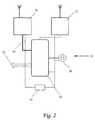
- FIG. 2is a block diagram of the smart tag shown in FIG. 1 ;
- FIG. 3is a block diagram of the ground base station shown in FIG. 1 ;
- FIG. 4is a block diagram of the beacon device shown in FIG. 1 ;
- FIG. 5is a flow chart of a method for using the AGPS tracking system according to an embodiment of the invention.
- the preferred technical solutionconstitutes precisely tracking a plurality of GPS smart tags affixed to the movable objects of interest.
- the GPS smart tagsare wirelessly linked to a service center via a plurality of ground stations covering a tracking area.
- a plurality of beacon devicesis disposed in the aforesaid tracking area.
- the beacon devicesare adapted to RF transmit their ID data to the smart tags situated within the beacon service area.
- Each smart tag situated in the coverage zone of the base stationis initialized under command of a service center.
- One method for determining the location of the smart tagcomprises the following steps: (i) determining an approximate location of the smart tag by identifying the nearest beacon device or by triangulating the smart tag position using beacon signal measurements and (ii) determining a precise location of the smart tag by means of an Assisted GPS (AGPS) technology.
- AGPSAssisted GPS
- the systemwhich is known as Assisted GPS or AGPS, uses a wireless network to provide the GPS receiver with data, thereby assisting it to acquire the satellite's signal.
- the systemprovides Ephemeris data to the GPS receiver, which improves the time-to-first-fix (TTFF).
- the data provided to the GPS receivercan be either the Ephemeris data for visible satellites or, more helpfully the code phase and Doppler ranges over which the GPS device has to search, i.e. ‘acquisition assistance’.
- This techniqueimproves the TTFF by many orders of magnitude, thus minimizing energy consumption.
- AGPSis also used to improve the sensitivity of the GPS device, thus improving the performance within buildings. By providing so called ‘sensitivity assistance’ (based roughly on the estimated position of the GPS receiver) to the GPS device, it is able to better correlate the signal being received from the satellite when the signal is low in strength.
- the smart tagBeing provided with assisted data, the smart tag receives satellite-broadcasted signals and calculates pseudo-ranges from the tag to the satellites. After transferring data, the smart tag is restored to a cold standby condition. The calculated pseudo-range data is transferred to the service center adapted to determine a smart tag location.
- Assisted GPSrelates to a configuration consisting of a GPS server and plurality of simple mobile GPS receivers connected via a communication link.
- the mobile GPS receiversare assisted by the GPS server providing data and processing power for position measurement.
- GPS smart tagrelates to tags consisting of a GPS receiver, limited processing power and an interface to a dedicated wireless communication link.
- Almanacrelates to coarse time information and status information about the satellites included in the primary navigation signal broadcasted by a satellite.
- Ephemerisrelates to information that allows the receiver to calculate the position of the satellite.
- Assisted datarelates to data generated by the service center and provided to the GPS smart tag for shortening Time To First Fix (“Acquisition Assistance”) and increasing sensitivity (“Sensitivity Assistance”).
- the aforesaid datacomprises at least one element selected from the group consisting of almanac, ephemeris, code phase, and Doppler ranges characterizing the satellite-broadcasted signal.
- Pseudo-rangerelates to the range of each of the satellites used by a GPS receiver and is calculated by the time delay of signals received from each satellite.
- the pseudo-range valuesare further used to calculate the GPS receiver position by triangulation.
- Radio frequency (RF) beaconrelates to a radio transmitter transmitting identification data within an area of the transmitter antenna.
- Central processing serverrelates to a central processing platform recording location data obtained from all the system smart tags in the database.
- Application serverrelates to a user interface platform.
- APIApplication interface
- System consolerelates to a terminal usable for operating the system.
- IPinternet protocol
- MCUis an acronym for a microcontroller unit.
- Receiveive Signal Strength Indicatorrefers to a circuit to measure the strength of an incoming signal.
- the basic circuitis designed to pick an RF signal and to generate an output equivalent to the signal strength.
- FIG. 1schematically illustrating a block diagram of an AGPS smart tag system 100 according to an exemplary embodiment of the invention.
- the system 100comprises a service center 16 , a ground base station 18 , a beacon 32 , and a smart tag 14 adapted to releasably affix to an object of interest 12 .
- the ground base station 18is connected to the service center 16 via IP network 30 .
- the service center 16further comprises a central processing server 24 , a customer application server 26 connected to the central processing server 24 via a application programming interface 25 , and stationary GPS receiver 22 furnished with an antenna 20 .
- the receiver 22 and the smart tag 14are adapted for to receive signals broadcasted by satellites 10 a . . .
- the ground base station 18is adapted to wirelessly RF-communicate with the smart tag 14 via a channel 44 .
- the stationary GPS receiver 22 furnished with the antenna 20is adapted for search and receive signals broadcasted by the satellites available for receiving.
- the beacon device 32has a service zone 34 .
- the smart tag 14 affixed to an object of interest 12is situated in the service zone 34 of the beacon device 32 .
- the smart tag 14is woken up by either itself when sensing predefined events (such as motion or time elapsed) or a command sent from the service center 16 . Being woken up, for example, by the service center 16 , the smart tag 14 receives a signal from the beacon device 32 via wireless communication channel 46 .
- the aforesaid signalcarries ID data of this specific beacon 32 .
- the smart tag 14measures parameters of the beacon signal and derives the beacon ID data. Further the beacon 32 retransmits the received beacon ID and signal measurement data to the service center 16 .
- the beacon ID dataenables the service center 16 to determine an approximate location of the smart tag 14 and provide the smart tag 14 with assisted data.
- the aforesaid datais generated according to satellite-broadcasted signals receivable by the stationary reference GPS receiver 22 .
- providing the smart tag 14 with assisted dataenables the system 100 to reduce energy consumption due to shortening TTFF (acquisition assistance) and more reliable reception (sensitivity assistance) that is very important in indoor conditions.
- TTFFacquisition assistance
- sensitivity assistancesensitivity assistance
- the smart tag 14performs signal search according to the received assisted data, receives satellite-broadcasted signals and calculates pseudo-ranges from the tag 14 to the available satellites 10 a , 10 b , 10 c , and 10 d .
- the calculated pseudo-rangesare transmitted to the service center 16 for further processing.
- the central processing server 24is adapted to calculate a location of the smart tag 14 by means of triangulating the obtained pseudo-ranges.
- FIG. 2presenting a block diagram of the AGPS smart tag 14 .
- the aforesaid smart tagcomprises an AGPS receiver 50 , an RF-transceiver 52 , a data bus 54 , a microcontroller unit 56 , a motion sensor 58 , a battery 60 , and I/O port 62 .
- the AGPS smart tag 14is in standby condition by default.
- the tagis woken up by either itself when sensing predefined events (such as motion or time elapsed) or a command sent from the service center 16 via the wireless RF-communication channel 44 .
- the transceiver 52receives a signal from the beacon device 32 via wireless communication channel 46 .
- the aforesaid signalcarries ID data of the specific beacon 32 .
- the microcontroller 56measures signal parameters and derives the beacon ID data.
- a received signal strength indicator and a phase delay or any combination thereofare measured by microcontroller 56 .
- the transceiver 52retransmits the received beacon ID and signal measurement data to the service center 16 .
- the beacon ID dataenables the service center 16 (not shown) to determine an approximate location of the smart tag 14 , generate the assisted data, and provide the smart tag 14 with the approximate location and the assisted data.
- the AGPS receiver 50searches and receives the satellite-broadcasted signals.
- the pseudo-random waveform received by GPS receiver 50is compared with an internally generated version of the same code with delay control, until both waveforms are synchronized.
- the obtained delay of internal pseudo-random form corresponding to the waveform synchronizationdefines the travel time of the GPS signal from the satellite to the receiver 50 .
- the obtained delay valuesare provided via the data bus 54 to the microcontroller unit 56 .
- the delay values(pseudo-ranges) further are transferred to the service center 16 via an RF-communication link 44 for calculating the smart tag location. Thereafter, the smart tag 14 restores to the standby condition.
- the smart tag 14is a mobile battery-powered device. Therefore, it is important that the suggested mode of short-time sessions of pseudo-range measurements secures a long battery service life.
- the smart tag 14further comprises a motion sensor 58 enabling the service center to assist tracking the smart tag 14 outside the service area.
- I/O port 62provides a connection of peripheral devices (not shown) to the smart tag 14 and two-way data interchange between the aforesaid device and the service center 16 .
- FIG. 3schematically illustrating a block diagram of the architecture of the ground base station 18 .
- the aforesaid base station 18is a ground communication unit communicating with the plurality of mobile smart tags via wireless communication links.
- the base station 18comprises four independent RF transceiver modules 70 a , 70 b , 70 e , and 70 d (rack transceiver) operating simultaneously.
- the rack transceiveris required for supporting the frequency diversity mode of operation, providing the required capabilities for withstanding external interferences.
- Microcontroller units 72 a , 72 b , 72 c , and 72 dperform management of the data stream in transceivers 70 a , 70 b , 70 e , and 70 d , respectively.
- a central microcontroller unit 74is responsible for activating and controlling internal operational logic of the base station 18 .
- a serial port 76connects peripheral devices to the base station 18 .
- the base station 18further comprises Ethernet chipset 78 for connecting to the Ethernet 30 .
- the base station 18is controlled by central processing server 24 via the Ethernet connection 30 .
- FIG. 4presenting a block diagram of the AC/DC ( 84 )-powered beacon device 32 comprising an RF-transceiver 80 capable of transmitting beacon device ID data at the predetermined frequency and time.
- the beacon device 32is furnished with an attenuator 82 and the serial or USB port 76 enabling the service center to change over the air a level of emitted power and configuring and maintaining the beacon device 32 , respectively.
- an AGPS systemhaving a smart tag.
- the smart tagis woken up at step 210 .
- the aforesaid smart tagmeasures RF-signals of the nearest beacon devices in-view and derives signal ID data of the nearest beacon device at step 220 .
- the smart tagthen retransmits signal measurement and ID data to the service center (step 230 ).
- the service centerdetermines an approximate location of the smart tag (step 240 ) and generates and transmits the assisted data (step 250 ).
- the assisted dataprovides both acquisition and sensitivity assistance. Stated another way, using the assisted data shortens TTFF and increases reliability of the objects location in indoor conditions.
- the smart tagreceives the satellite-broadcasted signals at the further step 260 according the assisted data.
- Calculating the pseudo-ranges at step 270is based on the obtained satellite signals.
- the calculated pseudo-rangesare transferred to the service center at the step 280 .
- Restoring the smart tag to the cold standby condition at the step 290secures reduced power consumption and enhances battery life.
- Calculating the tag location at the step 310ends the flowchart 300 .
- the obtained resultprovides coordinates characterizing the smart tag location.
- the reduction of power consumptionis attained due to initializing the smart tag by the service center during determining the smart tag location and restoring the aforesaid tag to the cold standby condition after transmitting the pseudo-ranges.
- the preliminary determination of the approximate tag location using the beacon devicesenables the service center to provide improved GPS assistance by means of transmitting more precise satellite data to the smart tag.
Landscapes
- Engineering & Computer Science (AREA)
- Radar, Positioning & Navigation (AREA)
- Remote Sensing (AREA)
- Physics & Mathematics (AREA)
- General Physics & Mathematics (AREA)
- Computer Networks & Wireless Communication (AREA)
- Position Fixing By Use Of Radio Waves (AREA)
Abstract
Description
Claims (18)
Priority Applications (1)
| Application Number | Priority Date | Filing Date | Title |
|---|---|---|---|
| US12/045,344US7855679B1 (en) | 2008-03-10 | 2008-03-10 | GPS system for tracking an object of interest and method for using the same |
Applications Claiming Priority (1)
| Application Number | Priority Date | Filing Date | Title |
|---|---|---|---|
| US12/045,344US7855679B1 (en) | 2008-03-10 | 2008-03-10 | GPS system for tracking an object of interest and method for using the same |
Publications (1)
| Publication Number | Publication Date |
|---|---|
| US7855679B1true US7855679B1 (en) | 2010-12-21 |
Family
ID=43333437
Family Applications (1)
| Application Number | Title | Priority Date | Filing Date |
|---|---|---|---|
| US12/045,344Expired - Fee RelatedUS7855679B1 (en) | 2008-03-10 | 2008-03-10 | GPS system for tracking an object of interest and method for using the same |
Country Status (1)
| Country | Link |
|---|---|
| US (1) | US7855679B1 (en) |
Cited By (17)
| Publication number | Priority date | Publication date | Assignee | Title |
|---|---|---|---|---|
| US20110054731A1 (en)* | 2009-08-31 | 2011-03-03 | Derose Lynn Ann | System and method for bi-directional wireless information transfer |
| US20120019412A1 (en)* | 2009-03-30 | 2012-01-26 | Ntt Docomo, Inc | Gps terminal, positioning method, communication system, and program |
| WO2013155386A1 (en)* | 2012-04-12 | 2013-10-17 | P.W. Precyse Wireless Ltd. | Gps positioning system |
| US8565628B2 (en) | 2011-03-04 | 2013-10-22 | Eastman Kodak Company | Electrophotographic non-uniformity compensation using intentional periodic variation |
| US9621347B2 (en) | 2014-09-03 | 2017-04-11 | Virtustream Ip Holding Company Llc | Systems and methods for securely provisioning the geographic location of physical infrastructure elements in cloud computing environments |
| US20170180930A1 (en)* | 2015-09-02 | 2017-06-22 | Estimote Polska Sp. Z O. O. | Systems and methods for object tracking with wireless beacons |
| US9826351B2 (en) | 2015-09-02 | 2017-11-21 | Estimote Polska Sp. Z O. O. | System and method for beacon fleet management |
| US9866996B1 (en) | 2016-07-07 | 2018-01-09 | Estimote Polska Sp. Z O. O. | Method and system for content delivery with a beacon |
| US9867009B2 (en) | 2016-03-22 | 2018-01-09 | Estimote Polska Sp. Z O. O. | System and method for multi-beacon interaction and management |
| US9955297B2 (en) | 2013-08-19 | 2018-04-24 | Estimote Polska Sp. Z O. O. | Systems and methods for object tracking using wireless beacons |
| US9998863B2 (en) | 2013-08-19 | 2018-06-12 | Estimote Polska Sp. Z O. O. | System and method for providing content using beacon systems |
| US10022853B1 (en) | 2017-07-05 | 2018-07-17 | Orazio Mollica | Power tools having integral GPS-based locating means |
| US10136250B2 (en) | 2015-09-02 | 2018-11-20 | Estimote Polska Sp. Z O. O. | System and method for lower power data routing |
| US10523685B1 (en) | 2018-08-22 | 2019-12-31 | Estimote Polska Sp z o.o. | System and method for verifying device security |
| CN110944282A (en)* | 2018-09-18 | 2020-03-31 | 深圳中集智能科技有限公司 | Intelligent sensing terminal capable of reducing power consumption and method for applying intelligent sensing terminal |
| US10852441B2 (en) | 2018-08-24 | 2020-12-01 | Estimote Polska Sp z o.o. | Method and system for asset management |
| EP4471461A4 (en)* | 2022-01-29 | 2025-04-30 | Queclink Wireless Solutions Co., Ltd. | Assisted positioning method and device, as well as electronic device and storage medium |
Citations (3)
| Publication number | Priority date | Publication date | Assignee | Title |
|---|---|---|---|---|
| US6700533B1 (en) | 1999-05-06 | 2004-03-02 | Rf Technologies, Inc. | Asset and personnel tagging system utilizing GPS |
| US20080027599A1 (en)* | 2006-07-28 | 2008-01-31 | James Logan | Autonomous vehicle and systems and methods for the operation thereof |
| US7633438B2 (en)* | 2007-01-29 | 2009-12-15 | Research In Motion Limited | Method of downloading ephemeris data based on user activity |
- 2008
- 2008-03-10USUS12/045,344patent/US7855679B1/ennot_activeExpired - Fee Related
Patent Citations (3)
| Publication number | Priority date | Publication date | Assignee | Title |
|---|---|---|---|---|
| US6700533B1 (en) | 1999-05-06 | 2004-03-02 | Rf Technologies, Inc. | Asset and personnel tagging system utilizing GPS |
| US20080027599A1 (en)* | 2006-07-28 | 2008-01-31 | James Logan | Autonomous vehicle and systems and methods for the operation thereof |
| US7633438B2 (en)* | 2007-01-29 | 2009-12-15 | Research In Motion Limited | Method of downloading ephemeris data based on user activity |
Cited By (34)
| Publication number | Priority date | Publication date | Assignee | Title |
|---|---|---|---|---|
| US20120019412A1 (en)* | 2009-03-30 | 2012-01-26 | Ntt Docomo, Inc | Gps terminal, positioning method, communication system, and program |
| US20110054731A1 (en)* | 2009-08-31 | 2011-03-03 | Derose Lynn Ann | System and method for bi-directional wireless information transfer |
| US8565628B2 (en) | 2011-03-04 | 2013-10-22 | Eastman Kodak Company | Electrophotographic non-uniformity compensation using intentional periodic variation |
| WO2013155386A1 (en)* | 2012-04-12 | 2013-10-17 | P.W. Precyse Wireless Ltd. | Gps positioning system |
| US11202171B2 (en) | 2013-08-19 | 2021-12-14 | Estimote Polska Sp z o.o. | System and method for providing content using beacon systems |
| US11297460B2 (en) | 2013-08-19 | 2022-04-05 | Estimote Polska Sp z o.o. | Wireless beacon and methods |
| US10244348B2 (en) | 2013-08-19 | 2019-03-26 | Estimote Polska Sp z o.o. | Methods for authenticating communication between a mobile device and wireless beacon at a remote domain name system, projecting a level of interest in a nearby product, and providing and ordering option or product data |
| US10856107B2 (en) | 2013-08-19 | 2020-12-01 | Estimote Polska Sp z o.o. | System and method for providing content using beacon systems |
| US9998863B2 (en) | 2013-08-19 | 2018-06-12 | Estimote Polska Sp. Z O. O. | System and method for providing content using beacon systems |
| US9955297B2 (en) | 2013-08-19 | 2018-04-24 | Estimote Polska Sp. Z O. O. | Systems and methods for object tracking using wireless beacons |
| US9621347B2 (en) | 2014-09-03 | 2017-04-11 | Virtustream Ip Holding Company Llc | Systems and methods for securely provisioning the geographic location of physical infrastructure elements in cloud computing environments |
| US9960921B2 (en) | 2014-09-03 | 2018-05-01 | Virtustream Ip Holding Company Llc | Systems and methods for securely provisioning the geographic location of physical infrastructure elements in cloud computing environments |
| US10616709B2 (en) | 2015-09-02 | 2020-04-07 | Estimote Polska Sp z o.o. | System and method for lower power data routing |
| US9942706B2 (en) | 2015-09-02 | 2018-04-10 | Estimote Polska Sp. Z O. O. | System and method for beacon fleet management |
| US9930486B2 (en) | 2015-09-02 | 2018-03-27 | Estimote Polska Sp. Z O. O. | Systems and methods for object tracking with wireless beacons |
| US20170180930A1 (en)* | 2015-09-02 | 2017-06-22 | Estimote Polska Sp. Z O. O. | Systems and methods for object tracking with wireless beacons |
| US10524083B2 (en) | 2015-09-02 | 2019-12-31 | Estimote Polska Sp z o.o. | System and method for low power data routing |
| US9826356B2 (en)* | 2015-09-02 | 2017-11-21 | Estimote Polska Sp. Z O. O. | Systems and methods for object tracking with wireless beacons |
| US10771917B2 (en) | 2015-09-02 | 2020-09-08 | Estimote Polska Sp z o.o. | System and method for low power data routing |
| US10136250B2 (en) | 2015-09-02 | 2018-11-20 | Estimote Polska Sp. Z O. O. | System and method for lower power data routing |
| US11006237B2 (en) | 2015-09-02 | 2021-05-11 | Estimote Polska Sp z o.o. | System and method for low power data routing |
| US9826351B2 (en) | 2015-09-02 | 2017-11-21 | Estimote Polska Sp. Z O. O. | System and method for beacon fleet management |
| US9872146B2 (en) | 2016-03-22 | 2018-01-16 | Estimote Polska Sp. Z O. O. | System and method for multi-beacon interaction and management |
| US10142786B2 (en) | 2016-03-22 | 2018-11-27 | Estimote Polska Sp. Z O. O. | System and method for multi-beacon interaction and management |
| US10009729B2 (en) | 2016-03-22 | 2018-06-26 | Estimote Polska Sp. Z O. O. | System and method for multi-beacon interaction and management |
| US9867009B2 (en) | 2016-03-22 | 2018-01-09 | Estimote Polska Sp. Z O. O. | System and method for multi-beacon interaction and management |
| US9866996B1 (en) | 2016-07-07 | 2018-01-09 | Estimote Polska Sp. Z O. O. | Method and system for content delivery with a beacon |
| US9936345B1 (en) | 2016-07-07 | 2018-04-03 | Estimote Polska Sp. Z O. O. | Method and system for content delivery with a beacon |
| US10022853B1 (en) | 2017-07-05 | 2018-07-17 | Orazio Mollica | Power tools having integral GPS-based locating means |
| US10523685B1 (en) | 2018-08-22 | 2019-12-31 | Estimote Polska Sp z o.o. | System and method for verifying device security |
| US11218492B2 (en) | 2018-08-22 | 2022-01-04 | Estimote Polska Sp. Z .O.O. | System and method for verifying device security |
| US10852441B2 (en) | 2018-08-24 | 2020-12-01 | Estimote Polska Sp z o.o. | Method and system for asset management |
| CN110944282A (en)* | 2018-09-18 | 2020-03-31 | 深圳中集智能科技有限公司 | Intelligent sensing terminal capable of reducing power consumption and method for applying intelligent sensing terminal |
| EP4471461A4 (en)* | 2022-01-29 | 2025-04-30 | Queclink Wireless Solutions Co., Ltd. | Assisted positioning method and device, as well as electronic device and storage medium |
Similar Documents
| Publication | Publication Date | Title |
|---|---|---|
| US7855679B1 (en) | GPS system for tracking an object of interest and method for using the same | |
| JP3978509B2 (en) | Method and system for determining the position of a tracked object | |
| US7994970B2 (en) | Positioning system, position information transmitter, communication terminal, and control method of the positioning system | |
| CN1902504B (en) | Method and apparatus for monitoring the integrity of satellite tracking data used by a remote receiver | |
| US6225945B1 (en) | GPS receiver using coarse orbital parameters for achieving a fast time to first fix | |
| US6700533B1 (en) | Asset and personnel tagging system utilizing GPS | |
| CN101142495B (en) | Method and apparatus for enhanced autonomous GPS | |
| US8299961B2 (en) | Method and system for selecting optimal satellites in view | |
| US12320906B2 (en) | Method and system for signal detection including positioning signals | |
| US7800531B2 (en) | High precision positioning system | |
| US8217832B2 (en) | Enhancing location accuracy using multiple satellite measurements based on environment | |
| US7277048B2 (en) | Asset tracking method | |
| US20150084813A1 (en) | Gps positioning system | |
| JP2002532724A5 (en) | ||
| JP2006502417A (en) | Method and apparatus for using long-term satellite tracking data in a remote receiver | |
| US20220413161A1 (en) | Indoor-outdoor dual-use high precision positioning system | |
| US6894645B1 (en) | Position estimation | |
| KR102268380B1 (en) | Method for measuring distance between mobile station using precise position measurement and system and method for measuring distance between golfer and hole cup using the same | |
| Wang et al. | Massive terminal positioning system with snapshot positioning technique | |
| US20100094554A1 (en) | Systems and Methods for Accessing Data Over a Short-range Data Link to Enhance the Performance of a Navigational Unit | |
| US9877157B2 (en) | Autonomous in-device GNSS augmentation system | |
| KR20100062678A (en) | A system of decreasing cold start time of gps and a method thereof | |
| US10795026B2 (en) | Navigation system and method | |
| JP2010071966A (en) | Method and device for measuring position by gnss (global navigation satellite system) satellite | |
| KR20010097037A (en) | Global positioning system |
Legal Events
| Date | Code | Title | Description |
|---|---|---|---|
| AS | Assignment | Owner name:PARALEC ISRAEL LTD., ISRAEL Free format text:ASSIGNMENT OF ASSIGNORS INTEREST;ASSIGNOR:BRAIMAN, MICHAEL;REEL/FRAME:020711/0655 Effective date:20071213 | |
| AS | Assignment | Owner name:PARELEC ISRAEL LTD., ISRAEL Free format text:CORRECTIVE ASSIGNMENT TO CORRECT THE ASSIGNEE PREVIOUSLY RECORDED ON REEL 020711 FRAME 0655. ASSIGNOR(S) HEREBY CONFIRMS THE ASSIGNMENT;ASSIGNOR:BRAIMAN, MICHAEL;REEL/FRAME:020734/0267 Effective date:20071213 | |
| AS | Assignment | Owner name:P.W. PRECYSE WIRELESS LTD, ISRAEL Free format text:CHANGE OF NAME;ASSIGNOR:PARELEC ISRAEL LTD;REEL/FRAME:024536/0115 Effective date:20091021 | |
| AS | Assignment | Owner name:PRECYSE INVESTMENT PARTNERS, LLC, GEORGIA Free format text:SECURITY AGREEMENT;ASSIGNOR:P.W. PRECYSE WIRELESS LTD.;REEL/FRAME:024806/0079 Effective date:20100716 | |
| AS | Assignment | Owner name:P.W. PRECYSE WIRELESS LTD., ISRAEL Free format text:RELEASE BY SECURED PARTY;ASSIGNOR:PRECYSE INVESTMENT PARTNERS, LLC;REEL/FRAME:025039/0751 Effective date:20100817 | |
| AS | Assignment | Owner name:PRECYSE TECHNOLOGIES, INC., GEORGIA Free format text:CHANGE OF NAME;ASSIGNOR:P.W. PRECYSE WIRELESS LTD;REEL/FRAME:025870/0181 Effective date:20110227 | |
| FPAY | Fee payment | Year of fee payment:4 | |
| AS | Assignment | Owner name:PRECYSE BRIDGE LENDER III, LLC, GEORGIA Free format text:SECURITY INTEREST;ASSIGNOR:PRECYSE TECHNOLOGIES, INC.;REEL/FRAME:034500/0975 Effective date:20141112 | |
| AS | Assignment | Owner name:PRECYSE TECHNOLOGIES FUNDING, LLC, GEORGIA Free format text:ASSIGNMENT OF ASSIGNORS INTEREST;ASSIGNOR:PRECYSE TECHNOLOGIES, INC.;REEL/FRAME:036976/0870 Effective date:20151028 | |
| AS | Assignment | Owner name:PRECYSE EMERGENCY FUNDING, LLC, GEORGIA Free format text:SECURITY INTEREST;ASSIGNOR:PRECYSE TECHNOLOGIES FUNDING, LLC;REEL/FRAME:037099/0001 Effective date:20151028 | |
| FEPP | Fee payment procedure | Free format text:MAINTENANCE FEE REMINDER MAILED (ORIGINAL EVENT CODE: REM.) | |
| AS | Assignment | Owner name:PRECYSE, INC., VIRGINIA Free format text:ASSIGNMENT OF ASSIGNORS INTEREST;ASSIGNOR:PRECYSE EMERGENCY FUNDING, LLC;REEL/FRAME:046837/0643 Effective date:20160330 Owner name:PRECYSE EMERGENCY FUNDING, LLC, GEORGIA Free format text:SURRENDER OF COLLATERAL, STRICT FORECLOSURE, AND RELEASE AGREEMENT;ASSIGNOR:PRECYSE TECHNOLOGIES FUNDING, LLC;REEL/FRAME:047049/0907 Effective date:20160223 | |
| LAPS | Lapse for failure to pay maintenance fees | Free format text:PATENT EXPIRED FOR FAILURE TO PAY MAINTENANCE FEES (ORIGINAL EVENT CODE: EXP.); ENTITY STATUS OF PATENT OWNER: SMALL ENTITY | |
| STCH | Information on status: patent discontinuation | Free format text:PATENT EXPIRED DUE TO NONPAYMENT OF MAINTENANCE FEES UNDER 37 CFR 1.362 | |
| FP | Lapsed due to failure to pay maintenance fee | Effective date:20181221 | |
| AS | Assignment | Owner name:THE ASSETS NET LLC, VIRGINIA Free format text:ASSIGNMENT OF ASSIGNORS INTEREST;ASSIGNOR:PRECYSE TECHNOLOGIES;REEL/FRAME:053505/0185 Effective date:20200814 |