US7854766B2 - Artificial total lumbar disc for unilateral safe and simple posterior placement in the lumbar spine, and removable bifunctional screw which drives vertical sliding expansile plate expansion, and interplate widening, and angled traction spikes - Google Patents
Artificial total lumbar disc for unilateral safe and simple posterior placement in the lumbar spine, and removable bifunctional screw which drives vertical sliding expansile plate expansion, and interplate widening, and angled traction spikesDownload PDFInfo
- Publication number
- US7854766B2 US7854766B2US11/487,415US48741506AUS7854766B2US 7854766 B2US7854766 B2US 7854766B2US 48741506 AUS48741506 AUS 48741506AUS 7854766 B2US7854766 B2US 7854766B2
- Authority
- US
- United States
- Prior art keywords
- axis
- plates
- pair
- total artificial
- substantially parallel
- Prior art date
- Legal status (The legal status is an assumption and is not a legal conclusion. Google has not performed a legal analysis and makes no representation as to the accuracy of the status listed.)
- Expired - Fee Related, expires
Links
- 230000001588bifunctional effectEffects0.000titleclaims9
- 210000004705lumbosacral regionAnatomy0.000titledescription6
- 230000033001locomotionEffects0.000claimsdescription31
- 238000001125extrusionMethods0.000claimsdescription15
- 239000000463materialSubstances0.000claimsdescription5
- 230000004888barrier functionEffects0.000claimsdescription3
- 238000003780insertionMethods0.000abstractdescription17
- 230000037431insertionEffects0.000abstractdescription17
- 238000000034methodMethods0.000abstractdescription7
- 239000004606Fillers/ExtendersSubstances0.000abstract1
- 238000013461designMethods0.000description13
- 230000035515penetrationEffects0.000description6
- 238000013459approachMethods0.000description5
- 230000008901benefitEffects0.000description5
- 230000007246mechanismEffects0.000description5
- 238000000926separation methodMethods0.000description5
- 210000000115thoracic cavityAnatomy0.000description5
- 230000002146bilateral effectEffects0.000description4
- 229910052751metalInorganic materials0.000description4
- 239000002184metalSubstances0.000description4
- 206010059604Radicular painDiseases0.000description3
- 206010038967Retrograde ejaculationDiseases0.000description3
- 208000024248Vascular System injuryDiseases0.000description3
- 208000012339Vascular injuryDiseases0.000description3
- 238000005452bendingMethods0.000description3
- 238000005516engineering processMethods0.000description3
- 239000000017hydrogelSubstances0.000description3
- 230000003993interactionEffects0.000description3
- 229920002635polyurethanePolymers0.000description3
- 239000004814polyurethaneSubstances0.000description3
- 238000004321preservationMethods0.000description3
- 206010002091AnaesthesiaDiseases0.000description2
- 229910000684Cobalt-chromeInorganic materials0.000description2
- RTAQQCXQSZGOHL-UHFFFAOYSA-NTitaniumChemical compound[Ti]RTAQQCXQSZGOHL-UHFFFAOYSA-N0.000description2
- 238000010521absorption reactionMethods0.000description2
- 230000037005anaesthesiaEffects0.000description2
- 239000010952cobalt-chromeSubstances0.000description2
- 230000003247decreasing effectEffects0.000description2
- 229920001971elastomerPolymers0.000description2
- 230000004927fusionEffects0.000description2
- 230000005484gravityEffects0.000description2
- 239000007943implantSubstances0.000description2
- 238000011065in-situ storageMethods0.000description2
- 238000010348incorporationMethods0.000description2
- 230000006698inductionEffects0.000description2
- 230000007774longtermEffects0.000description2
- 210000005036nerveAnatomy0.000description2
- 230000000399orthopedic effectEffects0.000description2
- 230000000306recurrent effectEffects0.000description2
- 230000035939shockEffects0.000description2
- 230000007480spreadingEffects0.000description2
- 229910001220stainless steelInorganic materials0.000description2
- 239000010935stainless steelSubstances0.000description2
- 230000000153supplemental effectEffects0.000description2
- 238000001356surgical procedureMethods0.000description2
- 229910052719titaniumInorganic materials0.000description2
- 239000010936titaniumSubstances0.000description2
- 238000013519translationMethods0.000description2
- 210000002517zygapophyseal jointAnatomy0.000description2
- 239000004705High-molecular-weight polyethyleneSubstances0.000description1
- 208000003618Intervertebral Disc DisplacementDiseases0.000description1
- 241001465754MetazoaSpecies0.000description1
- 235000010627Phaseolus vulgarisNutrition0.000description1
- 244000046052Phaseolus vulgarisSpecies0.000description1
- 239000004698PolyethyleneSubstances0.000description1
- 239000004372Polyvinyl alcoholSubstances0.000description1
- 229920010741Ultra High Molecular Weight Polyethylene (UHMWPE)Polymers0.000description1
- 239000004699Ultra-high molecular weight polyethyleneSubstances0.000description1
- 208000027418Wounds and injuryDiseases0.000description1
- WAIPAZQMEIHHTJ-UHFFFAOYSA-N[Cr].[Co]Chemical compound[Cr].[Co]WAIPAZQMEIHHTJ-UHFFFAOYSA-N0.000description1
- 230000009471actionEffects0.000description1
- 210000003484anatomyAnatomy0.000description1
- 238000011882arthroplastyMethods0.000description1
- 230000003416augmentationEffects0.000description1
- 230000003190augmentative effectEffects0.000description1
- 230000000975bioactive effectEffects0.000description1
- 230000005540biological transmissionEffects0.000description1
- 239000008280bloodSubstances0.000description1
- 210000004369bloodAnatomy0.000description1
- 210000000988bone and boneAnatomy0.000description1
- 230000006378damageEffects0.000description1
- 230000003467diminishing effectEffects0.000description1
- 201000010099diseaseDiseases0.000description1
- 208000037265diseases, disorders, signs and symptomsDiseases0.000description1
- 239000000806elastomerSubstances0.000description1
- 230000002708enhancing effectEffects0.000description1
- 239000004744fabricSubstances0.000description1
- 230000002349favourable effectEffects0.000description1
- 239000000835fiberSubstances0.000description1
- 230000006870functionEffects0.000description1
- 238000003306harvestingMethods0.000description1
- 238000011540hip replacementMethods0.000description1
- 150000004677hydratesChemical class0.000description1
- 238000002513implantationMethods0.000description1
- 230000006872improvementEffects0.000description1
- 230000010354integrationEffects0.000description1
- 238000013150knee replacementMethods0.000description1
- 230000003278mimic effectEffects0.000description1
- 238000012986modificationMethods0.000description1
- 230000004048modificationEffects0.000description1
- 230000007170pathologyEffects0.000description1
- 230000002093peripheral effectEffects0.000description1
- 229920001692polycarbonate urethanePolymers0.000description1
- -1polyethylenePolymers0.000description1
- 229920000573polyethylenePolymers0.000description1
- 229920000098polyolefinPolymers0.000description1
- 229920002451polyvinyl alcoholPolymers0.000description1
- 102000004169proteins and genesHuman genes0.000description1
- 108090000623proteins and genesProteins0.000description1
- 229910052710siliconInorganic materials0.000description1
- 239000010703siliconSubstances0.000description1
- 229920000785ultra high molecular weight polyethylenePolymers0.000description1
- 230000002792vascularEffects0.000description1
Images


Classifications
- A—HUMAN NECESSITIES
- A61—MEDICAL OR VETERINARY SCIENCE; HYGIENE
- A61F—FILTERS IMPLANTABLE INTO BLOOD VESSELS; PROSTHESES; DEVICES PROVIDING PATENCY TO, OR PREVENTING COLLAPSING OF, TUBULAR STRUCTURES OF THE BODY, e.g. STENTS; ORTHOPAEDIC, NURSING OR CONTRACEPTIVE DEVICES; FOMENTATION; TREATMENT OR PROTECTION OF EYES OR EARS; BANDAGES, DRESSINGS OR ABSORBENT PADS; FIRST-AID KITS
- A61F2/00—Filters implantable into blood vessels; Prostheses, i.e. artificial substitutes or replacements for parts of the body; Appliances for connecting them with the body; Devices providing patency to, or preventing collapsing of, tubular structures of the body, e.g. stents
- A61F2/02—Prostheses implantable into the body
- A61F2/30—Joints
- A61F2/46—Special tools for implanting artificial joints
- A61F2/4603—Special tools for implanting artificial joints for insertion or extraction of endoprosthetic joints or of accessories thereof
- A61F2/4611—Special tools for implanting artificial joints for insertion or extraction of endoprosthetic joints or of accessories thereof of spinal prostheses
- A—HUMAN NECESSITIES
- A61—MEDICAL OR VETERINARY SCIENCE; HYGIENE
- A61F—FILTERS IMPLANTABLE INTO BLOOD VESSELS; PROSTHESES; DEVICES PROVIDING PATENCY TO, OR PREVENTING COLLAPSING OF, TUBULAR STRUCTURES OF THE BODY, e.g. STENTS; ORTHOPAEDIC, NURSING OR CONTRACEPTIVE DEVICES; FOMENTATION; TREATMENT OR PROTECTION OF EYES OR EARS; BANDAGES, DRESSINGS OR ABSORBENT PADS; FIRST-AID KITS
- A61F2/00—Filters implantable into blood vessels; Prostheses, i.e. artificial substitutes or replacements for parts of the body; Appliances for connecting them with the body; Devices providing patency to, or preventing collapsing of, tubular structures of the body, e.g. stents
- A61F2/02—Prostheses implantable into the body
- A61F2/30—Joints
- A61F2/44—Joints for the spine, e.g. vertebrae, spinal discs
- A61F2/442—Intervertebral or spinal discs, e.g. resilient
- A—HUMAN NECESSITIES
- A61—MEDICAL OR VETERINARY SCIENCE; HYGIENE
- A61F—FILTERS IMPLANTABLE INTO BLOOD VESSELS; PROSTHESES; DEVICES PROVIDING PATENCY TO, OR PREVENTING COLLAPSING OF, TUBULAR STRUCTURES OF THE BODY, e.g. STENTS; ORTHOPAEDIC, NURSING OR CONTRACEPTIVE DEVICES; FOMENTATION; TREATMENT OR PROTECTION OF EYES OR EARS; BANDAGES, DRESSINGS OR ABSORBENT PADS; FIRST-AID KITS
- A61F2/00—Filters implantable into blood vessels; Prostheses, i.e. artificial substitutes or replacements for parts of the body; Appliances for connecting them with the body; Devices providing patency to, or preventing collapsing of, tubular structures of the body, e.g. stents
- A61F2/02—Prostheses implantable into the body
- A61F2/30—Joints
- A61F2002/30001—Additional features of subject-matter classified in A61F2/28, A61F2/30 and subgroups thereof
- A61F2002/30108—Shapes
- A61F2002/3011—Cross-sections or two-dimensional shapes
- A61F2002/30112—Rounded shapes, e.g. with rounded corners
- A61F2002/30133—Rounded shapes, e.g. with rounded corners kidney-shaped or bean-shaped
- A—HUMAN NECESSITIES
- A61—MEDICAL OR VETERINARY SCIENCE; HYGIENE
- A61F—FILTERS IMPLANTABLE INTO BLOOD VESSELS; PROSTHESES; DEVICES PROVIDING PATENCY TO, OR PREVENTING COLLAPSING OF, TUBULAR STRUCTURES OF THE BODY, e.g. STENTS; ORTHOPAEDIC, NURSING OR CONTRACEPTIVE DEVICES; FOMENTATION; TREATMENT OR PROTECTION OF EYES OR EARS; BANDAGES, DRESSINGS OR ABSORBENT PADS; FIRST-AID KITS
- A61F2/00—Filters implantable into blood vessels; Prostheses, i.e. artificial substitutes or replacements for parts of the body; Appliances for connecting them with the body; Devices providing patency to, or preventing collapsing of, tubular structures of the body, e.g. stents
- A61F2/02—Prostheses implantable into the body
- A61F2/30—Joints
- A61F2002/30001—Additional features of subject-matter classified in A61F2/28, A61F2/30 and subgroups thereof
- A61F2002/30108—Shapes
- A61F2002/30199—Three-dimensional shapes
- A61F2002/30242—Three-dimensional shapes spherical
- A—HUMAN NECESSITIES
- A61—MEDICAL OR VETERINARY SCIENCE; HYGIENE
- A61F—FILTERS IMPLANTABLE INTO BLOOD VESSELS; PROSTHESES; DEVICES PROVIDING PATENCY TO, OR PREVENTING COLLAPSING OF, TUBULAR STRUCTURES OF THE BODY, e.g. STENTS; ORTHOPAEDIC, NURSING OR CONTRACEPTIVE DEVICES; FOMENTATION; TREATMENT OR PROTECTION OF EYES OR EARS; BANDAGES, DRESSINGS OR ABSORBENT PADS; FIRST-AID KITS
- A61F2/00—Filters implantable into blood vessels; Prostheses, i.e. artificial substitutes or replacements for parts of the body; Appliances for connecting them with the body; Devices providing patency to, or preventing collapsing of, tubular structures of the body, e.g. stents
- A61F2/02—Prostheses implantable into the body
- A61F2/30—Joints
- A61F2002/30001—Additional features of subject-matter classified in A61F2/28, A61F2/30 and subgroups thereof
- A61F2002/30316—The prosthesis having different structural features at different locations within the same prosthesis; Connections between prosthetic parts; Special structural features of bone or joint prostheses not otherwise provided for
- A61F2002/30329—Connections or couplings between prosthetic parts, e.g. between modular parts; Connecting elements
- A61F2002/30476—Connections or couplings between prosthetic parts, e.g. between modular parts; Connecting elements locked by an additional locking mechanism
- A61F2002/305—Snap connection
- A—HUMAN NECESSITIES
- A61—MEDICAL OR VETERINARY SCIENCE; HYGIENE
- A61F—FILTERS IMPLANTABLE INTO BLOOD VESSELS; PROSTHESES; DEVICES PROVIDING PATENCY TO, OR PREVENTING COLLAPSING OF, TUBULAR STRUCTURES OF THE BODY, e.g. STENTS; ORTHOPAEDIC, NURSING OR CONTRACEPTIVE DEVICES; FOMENTATION; TREATMENT OR PROTECTION OF EYES OR EARS; BANDAGES, DRESSINGS OR ABSORBENT PADS; FIRST-AID KITS
- A61F2/00—Filters implantable into blood vessels; Prostheses, i.e. artificial substitutes or replacements for parts of the body; Appliances for connecting them with the body; Devices providing patency to, or preventing collapsing of, tubular structures of the body, e.g. stents
- A61F2/02—Prostheses implantable into the body
- A61F2/30—Joints
- A61F2002/30001—Additional features of subject-matter classified in A61F2/28, A61F2/30 and subgroups thereof
- A61F2002/30316—The prosthesis having different structural features at different locations within the same prosthesis; Connections between prosthetic parts; Special structural features of bone or joint prostheses not otherwise provided for
- A61F2002/30329—Connections or couplings between prosthetic parts, e.g. between modular parts; Connecting elements
- A61F2002/30518—Connections or couplings between prosthetic parts, e.g. between modular parts; Connecting elements with possibility of relative movement between the prosthetic parts
- A61F2002/30523—Connections or couplings between prosthetic parts, e.g. between modular parts; Connecting elements with possibility of relative movement between the prosthetic parts by means of meshing gear teeth
- A61F2002/30525—Worm gears
- A—HUMAN NECESSITIES
- A61—MEDICAL OR VETERINARY SCIENCE; HYGIENE
- A61F—FILTERS IMPLANTABLE INTO BLOOD VESSELS; PROSTHESES; DEVICES PROVIDING PATENCY TO, OR PREVENTING COLLAPSING OF, TUBULAR STRUCTURES OF THE BODY, e.g. STENTS; ORTHOPAEDIC, NURSING OR CONTRACEPTIVE DEVICES; FOMENTATION; TREATMENT OR PROTECTION OF EYES OR EARS; BANDAGES, DRESSINGS OR ABSORBENT PADS; FIRST-AID KITS
- A61F2/00—Filters implantable into blood vessels; Prostheses, i.e. artificial substitutes or replacements for parts of the body; Appliances for connecting them with the body; Devices providing patency to, or preventing collapsing of, tubular structures of the body, e.g. stents
- A61F2/02—Prostheses implantable into the body
- A61F2/30—Joints
- A61F2002/30001—Additional features of subject-matter classified in A61F2/28, A61F2/30 and subgroups thereof
- A61F2002/30316—The prosthesis having different structural features at different locations within the same prosthesis; Connections between prosthetic parts; Special structural features of bone or joint prostheses not otherwise provided for
- A61F2002/30535—Special structural features of bone or joint prostheses not otherwise provided for
- A61F2002/30537—Special structural features of bone or joint prostheses not otherwise provided for adjustable
- A61F2002/30538—Special structural features of bone or joint prostheses not otherwise provided for adjustable for adjusting angular orientation
- A—HUMAN NECESSITIES
- A61—MEDICAL OR VETERINARY SCIENCE; HYGIENE
- A61F—FILTERS IMPLANTABLE INTO BLOOD VESSELS; PROSTHESES; DEVICES PROVIDING PATENCY TO, OR PREVENTING COLLAPSING OF, TUBULAR STRUCTURES OF THE BODY, e.g. STENTS; ORTHOPAEDIC, NURSING OR CONTRACEPTIVE DEVICES; FOMENTATION; TREATMENT OR PROTECTION OF EYES OR EARS; BANDAGES, DRESSINGS OR ABSORBENT PADS; FIRST-AID KITS
- A61F2/00—Filters implantable into blood vessels; Prostheses, i.e. artificial substitutes or replacements for parts of the body; Appliances for connecting them with the body; Devices providing patency to, or preventing collapsing of, tubular structures of the body, e.g. stents
- A61F2/02—Prostheses implantable into the body
- A61F2/30—Joints
- A61F2002/30001—Additional features of subject-matter classified in A61F2/28, A61F2/30 and subgroups thereof
- A61F2002/30316—The prosthesis having different structural features at different locations within the same prosthesis; Connections between prosthetic parts; Special structural features of bone or joint prostheses not otherwise provided for
- A61F2002/30535—Special structural features of bone or joint prostheses not otherwise provided for
- A61F2002/30537—Special structural features of bone or joint prostheses not otherwise provided for adjustable
- A61F2002/3055—Special structural features of bone or joint prostheses not otherwise provided for adjustable for adjusting length
- A—HUMAN NECESSITIES
- A61—MEDICAL OR VETERINARY SCIENCE; HYGIENE
- A61F—FILTERS IMPLANTABLE INTO BLOOD VESSELS; PROSTHESES; DEVICES PROVIDING PATENCY TO, OR PREVENTING COLLAPSING OF, TUBULAR STRUCTURES OF THE BODY, e.g. STENTS; ORTHOPAEDIC, NURSING OR CONTRACEPTIVE DEVICES; FOMENTATION; TREATMENT OR PROTECTION OF EYES OR EARS; BANDAGES, DRESSINGS OR ABSORBENT PADS; FIRST-AID KITS
- A61F2/00—Filters implantable into blood vessels; Prostheses, i.e. artificial substitutes or replacements for parts of the body; Appliances for connecting them with the body; Devices providing patency to, or preventing collapsing of, tubular structures of the body, e.g. stents
- A61F2/02—Prostheses implantable into the body
- A61F2/30—Joints
- A61F2002/30001—Additional features of subject-matter classified in A61F2/28, A61F2/30 and subgroups thereof
- A61F2002/30316—The prosthesis having different structural features at different locations within the same prosthesis; Connections between prosthetic parts; Special structural features of bone or joint prostheses not otherwise provided for
- A61F2002/30535—Special structural features of bone or joint prostheses not otherwise provided for
- A61F2002/30537—Special structural features of bone or joint prostheses not otherwise provided for adjustable
- A61F2002/30556—Special structural features of bone or joint prostheses not otherwise provided for adjustable for adjusting thickness
- A—HUMAN NECESSITIES
- A61—MEDICAL OR VETERINARY SCIENCE; HYGIENE
- A61F—FILTERS IMPLANTABLE INTO BLOOD VESSELS; PROSTHESES; DEVICES PROVIDING PATENCY TO, OR PREVENTING COLLAPSING OF, TUBULAR STRUCTURES OF THE BODY, e.g. STENTS; ORTHOPAEDIC, NURSING OR CONTRACEPTIVE DEVICES; FOMENTATION; TREATMENT OR PROTECTION OF EYES OR EARS; BANDAGES, DRESSINGS OR ABSORBENT PADS; FIRST-AID KITS
- A61F2/00—Filters implantable into blood vessels; Prostheses, i.e. artificial substitutes or replacements for parts of the body; Appliances for connecting them with the body; Devices providing patency to, or preventing collapsing of, tubular structures of the body, e.g. stents
- A61F2/02—Prostheses implantable into the body
- A61F2/30—Joints
- A61F2002/30001—Additional features of subject-matter classified in A61F2/28, A61F2/30 and subgroups thereof
- A61F2002/30316—The prosthesis having different structural features at different locations within the same prosthesis; Connections between prosthetic parts; Special structural features of bone or joint prostheses not otherwise provided for
- A61F2002/30535—Special structural features of bone or joint prostheses not otherwise provided for
- A61F2002/30579—Special structural features of bone or joint prostheses not otherwise provided for with mechanically expandable devices, e.g. fixation devices
- A—HUMAN NECESSITIES
- A61—MEDICAL OR VETERINARY SCIENCE; HYGIENE
- A61F—FILTERS IMPLANTABLE INTO BLOOD VESSELS; PROSTHESES; DEVICES PROVIDING PATENCY TO, OR PREVENTING COLLAPSING OF, TUBULAR STRUCTURES OF THE BODY, e.g. STENTS; ORTHOPAEDIC, NURSING OR CONTRACEPTIVE DEVICES; FOMENTATION; TREATMENT OR PROTECTION OF EYES OR EARS; BANDAGES, DRESSINGS OR ABSORBENT PADS; FIRST-AID KITS
- A61F2/00—Filters implantable into blood vessels; Prostheses, i.e. artificial substitutes or replacements for parts of the body; Appliances for connecting them with the body; Devices providing patency to, or preventing collapsing of, tubular structures of the body, e.g. stents
- A61F2/02—Prostheses implantable into the body
- A61F2/30—Joints
- A61F2002/30001—Additional features of subject-matter classified in A61F2/28, A61F2/30 and subgroups thereof
- A61F2002/30621—Features concerning the anatomical functioning or articulation of the prosthetic joint
- A61F2002/30649—Ball-and-socket joints
- A61F2002/30663—Ball-and-socket joints multiaxial, e.g. biaxial; multipolar, e.g. bipolar or having an intermediate shell articulating between the ball and the socket
- A—HUMAN NECESSITIES
- A61—MEDICAL OR VETERINARY SCIENCE; HYGIENE
- A61F—FILTERS IMPLANTABLE INTO BLOOD VESSELS; PROSTHESES; DEVICES PROVIDING PATENCY TO, OR PREVENTING COLLAPSING OF, TUBULAR STRUCTURES OF THE BODY, e.g. STENTS; ORTHOPAEDIC, NURSING OR CONTRACEPTIVE DEVICES; FOMENTATION; TREATMENT OR PROTECTION OF EYES OR EARS; BANDAGES, DRESSINGS OR ABSORBENT PADS; FIRST-AID KITS
- A61F2/00—Filters implantable into blood vessels; Prostheses, i.e. artificial substitutes or replacements for parts of the body; Appliances for connecting them with the body; Devices providing patency to, or preventing collapsing of, tubular structures of the body, e.g. stents
- A61F2/02—Prostheses implantable into the body
- A61F2/30—Joints
- A61F2/30767—Special external or bone-contacting surface, e.g. coating for improving bone ingrowth
- A61F2/30771—Special external or bone-contacting surface, e.g. coating for improving bone ingrowth applied in original prostheses, e.g. holes or grooves
- A61F2002/30841—Sharp anchoring protrusions for impaction into the bone, e.g. sharp pins, spikes
- A—HUMAN NECESSITIES
- A61—MEDICAL OR VETERINARY SCIENCE; HYGIENE
- A61F—FILTERS IMPLANTABLE INTO BLOOD VESSELS; PROSTHESES; DEVICES PROVIDING PATENCY TO, OR PREVENTING COLLAPSING OF, TUBULAR STRUCTURES OF THE BODY, e.g. STENTS; ORTHOPAEDIC, NURSING OR CONTRACEPTIVE DEVICES; FOMENTATION; TREATMENT OR PROTECTION OF EYES OR EARS; BANDAGES, DRESSINGS OR ABSORBENT PADS; FIRST-AID KITS
- A61F2/00—Filters implantable into blood vessels; Prostheses, i.e. artificial substitutes or replacements for parts of the body; Appliances for connecting them with the body; Devices providing patency to, or preventing collapsing of, tubular structures of the body, e.g. stents
- A61F2/02—Prostheses implantable into the body
- A61F2/30—Joints
- A61F2/46—Special tools for implanting artificial joints
- A61F2/4603—Special tools for implanting artificial joints for insertion or extraction of endoprosthetic joints or of accessories thereof
- A61F2002/4622—Special tools for implanting artificial joints for insertion or extraction of endoprosthetic joints or of accessories thereof having the shape of a forceps or a clamp
- A—HUMAN NECESSITIES
- A61—MEDICAL OR VETERINARY SCIENCE; HYGIENE
- A61F—FILTERS IMPLANTABLE INTO BLOOD VESSELS; PROSTHESES; DEVICES PROVIDING PATENCY TO, OR PREVENTING COLLAPSING OF, TUBULAR STRUCTURES OF THE BODY, e.g. STENTS; ORTHOPAEDIC, NURSING OR CONTRACEPTIVE DEVICES; FOMENTATION; TREATMENT OR PROTECTION OF EYES OR EARS; BANDAGES, DRESSINGS OR ABSORBENT PADS; FIRST-AID KITS
- A61F2/00—Filters implantable into blood vessels; Prostheses, i.e. artificial substitutes or replacements for parts of the body; Appliances for connecting them with the body; Devices providing patency to, or preventing collapsing of, tubular structures of the body, e.g. stents
- A61F2/02—Prostheses implantable into the body
- A61F2/30—Joints
- A61F2/46—Special tools for implanting artificial joints
- A61F2/4603—Special tools for implanting artificial joints for insertion or extraction of endoprosthetic joints or of accessories thereof
- A61F2002/4625—Special tools for implanting artificial joints for insertion or extraction of endoprosthetic joints or of accessories thereof with relative movement between parts of the instrument during use
- A61F2002/4627—Special tools for implanting artificial joints for insertion or extraction of endoprosthetic joints or of accessories thereof with relative movement between parts of the instrument during use with linear motion along or rotating motion about the instrument axis or the implantation direction, e.g. telescopic, along a guiding rod, screwing inside the instrument
- A—HUMAN NECESSITIES
- A61—MEDICAL OR VETERINARY SCIENCE; HYGIENE
- A61F—FILTERS IMPLANTABLE INTO BLOOD VESSELS; PROSTHESES; DEVICES PROVIDING PATENCY TO, OR PREVENTING COLLAPSING OF, TUBULAR STRUCTURES OF THE BODY, e.g. STENTS; ORTHOPAEDIC, NURSING OR CONTRACEPTIVE DEVICES; FOMENTATION; TREATMENT OR PROTECTION OF EYES OR EARS; BANDAGES, DRESSINGS OR ABSORBENT PADS; FIRST-AID KITS
- A61F2/00—Filters implantable into blood vessels; Prostheses, i.e. artificial substitutes or replacements for parts of the body; Appliances for connecting them with the body; Devices providing patency to, or preventing collapsing of, tubular structures of the body, e.g. stents
- A61F2/02—Prostheses implantable into the body
- A61F2/30—Joints
- A61F2/46—Special tools for implanting artificial joints
- A61F2/4603—Special tools for implanting artificial joints for insertion or extraction of endoprosthetic joints or of accessories thereof
- A61F2002/4625—Special tools for implanting artificial joints for insertion or extraction of endoprosthetic joints or of accessories thereof with relative movement between parts of the instrument during use
- A61F2002/4628—Special tools for implanting artificial joints for insertion or extraction of endoprosthetic joints or of accessories thereof with relative movement between parts of the instrument during use with linear motion along or rotating motion about an axis transverse to the instrument axis or to the implantation direction, e.g. clamping
- A—HUMAN NECESSITIES
- A61—MEDICAL OR VETERINARY SCIENCE; HYGIENE
- A61F—FILTERS IMPLANTABLE INTO BLOOD VESSELS; PROSTHESES; DEVICES PROVIDING PATENCY TO, OR PREVENTING COLLAPSING OF, TUBULAR STRUCTURES OF THE BODY, e.g. STENTS; ORTHOPAEDIC, NURSING OR CONTRACEPTIVE DEVICES; FOMENTATION; TREATMENT OR PROTECTION OF EYES OR EARS; BANDAGES, DRESSINGS OR ABSORBENT PADS; FIRST-AID KITS
- A61F2220/00—Fixations or connections for prostheses classified in groups A61F2/00 - A61F2/26 or A61F2/82 or A61F9/00 or A61F11/00 or subgroups thereof
- A61F2220/0025—Connections or couplings between prosthetic parts, e.g. between modular parts; Connecting elements
- A—HUMAN NECESSITIES
- A61—MEDICAL OR VETERINARY SCIENCE; HYGIENE
- A61F—FILTERS IMPLANTABLE INTO BLOOD VESSELS; PROSTHESES; DEVICES PROVIDING PATENCY TO, OR PREVENTING COLLAPSING OF, TUBULAR STRUCTURES OF THE BODY, e.g. STENTS; ORTHOPAEDIC, NURSING OR CONTRACEPTIVE DEVICES; FOMENTATION; TREATMENT OR PROTECTION OF EYES OR EARS; BANDAGES, DRESSINGS OR ABSORBENT PADS; FIRST-AID KITS
- A61F2230/00—Geometry of prostheses classified in groups A61F2/00 - A61F2/26 or A61F2/82 or A61F9/00 or A61F11/00 or subgroups thereof
- A61F2230/0002—Two-dimensional shapes, e.g. cross-sections
- A61F2230/0004—Rounded shapes, e.g. with rounded corners
- A61F2230/0015—Kidney-shaped, e.g. bean-shaped
- A—HUMAN NECESSITIES
- A61—MEDICAL OR VETERINARY SCIENCE; HYGIENE
- A61F—FILTERS IMPLANTABLE INTO BLOOD VESSELS; PROSTHESES; DEVICES PROVIDING PATENCY TO, OR PREVENTING COLLAPSING OF, TUBULAR STRUCTURES OF THE BODY, e.g. STENTS; ORTHOPAEDIC, NURSING OR CONTRACEPTIVE DEVICES; FOMENTATION; TREATMENT OR PROTECTION OF EYES OR EARS; BANDAGES, DRESSINGS OR ABSORBENT PADS; FIRST-AID KITS
- A61F2230/00—Geometry of prostheses classified in groups A61F2/00 - A61F2/26 or A61F2/82 or A61F9/00 or A61F11/00 or subgroups thereof
- A61F2230/0063—Three-dimensional shapes
- A61F2230/0071—Three-dimensional shapes spherical
- A—HUMAN NECESSITIES
- A61—MEDICAL OR VETERINARY SCIENCE; HYGIENE
- A61F—FILTERS IMPLANTABLE INTO BLOOD VESSELS; PROSTHESES; DEVICES PROVIDING PATENCY TO, OR PREVENTING COLLAPSING OF, TUBULAR STRUCTURES OF THE BODY, e.g. STENTS; ORTHOPAEDIC, NURSING OR CONTRACEPTIVE DEVICES; FOMENTATION; TREATMENT OR PROTECTION OF EYES OR EARS; BANDAGES, DRESSINGS OR ABSORBENT PADS; FIRST-AID KITS
- A61F2250/00—Special features of prostheses classified in groups A61F2/00 - A61F2/26 or A61F2/82 or A61F9/00 or A61F11/00 or subgroups thereof
- A61F2250/0004—Special features of prostheses classified in groups A61F2/00 - A61F2/26 or A61F2/82 or A61F9/00 or A61F11/00 or subgroups thereof adjustable
- A61F2250/0006—Special features of prostheses classified in groups A61F2/00 - A61F2/26 or A61F2/82 or A61F9/00 or A61F11/00 or subgroups thereof adjustable for adjusting angular orientation
- A—HUMAN NECESSITIES
- A61—MEDICAL OR VETERINARY SCIENCE; HYGIENE
- A61F—FILTERS IMPLANTABLE INTO BLOOD VESSELS; PROSTHESES; DEVICES PROVIDING PATENCY TO, OR PREVENTING COLLAPSING OF, TUBULAR STRUCTURES OF THE BODY, e.g. STENTS; ORTHOPAEDIC, NURSING OR CONTRACEPTIVE DEVICES; FOMENTATION; TREATMENT OR PROTECTION OF EYES OR EARS; BANDAGES, DRESSINGS OR ABSORBENT PADS; FIRST-AID KITS
- A61F2250/00—Special features of prostheses classified in groups A61F2/00 - A61F2/26 or A61F2/82 or A61F9/00 or A61F11/00 or subgroups thereof
- A61F2250/0004—Special features of prostheses classified in groups A61F2/00 - A61F2/26 or A61F2/82 or A61F9/00 or A61F11/00 or subgroups thereof adjustable
- A61F2250/0009—Special features of prostheses classified in groups A61F2/00 - A61F2/26 or A61F2/82 or A61F9/00 or A61F11/00 or subgroups thereof adjustable for adjusting thickness
- A—HUMAN NECESSITIES
- A61—MEDICAL OR VETERINARY SCIENCE; HYGIENE
- A61F—FILTERS IMPLANTABLE INTO BLOOD VESSELS; PROSTHESES; DEVICES PROVIDING PATENCY TO, OR PREVENTING COLLAPSING OF, TUBULAR STRUCTURES OF THE BODY, e.g. STENTS; ORTHOPAEDIC, NURSING OR CONTRACEPTIVE DEVICES; FOMENTATION; TREATMENT OR PROTECTION OF EYES OR EARS; BANDAGES, DRESSINGS OR ABSORBENT PADS; FIRST-AID KITS
- A61F2310/00—Prostheses classified in A61F2/28 or A61F2/30 - A61F2/44 being constructed from or coated with a particular material
- A61F2310/00005—The prosthesis being constructed from a particular material
- A61F2310/00011—Metals or alloys
- A61F2310/00023—Titanium or titanium-based alloys, e.g. Ti-Ni alloys
- A—HUMAN NECESSITIES
- A61—MEDICAL OR VETERINARY SCIENCE; HYGIENE
- A61F—FILTERS IMPLANTABLE INTO BLOOD VESSELS; PROSTHESES; DEVICES PROVIDING PATENCY TO, OR PREVENTING COLLAPSING OF, TUBULAR STRUCTURES OF THE BODY, e.g. STENTS; ORTHOPAEDIC, NURSING OR CONTRACEPTIVE DEVICES; FOMENTATION; TREATMENT OR PROTECTION OF EYES OR EARS; BANDAGES, DRESSINGS OR ABSORBENT PADS; FIRST-AID KITS
- A61F2310/00—Prostheses classified in A61F2/28 or A61F2/30 - A61F2/44 being constructed from or coated with a particular material
- A61F2310/00005—The prosthesis being constructed from a particular material
- A61F2310/00011—Metals or alloys
- A61F2310/00029—Cobalt-based alloys, e.g. Co-Cr alloys or Vitallium
Definitions
- the present inventionrelates to a posterior placed total lumbar artificial disc (“PTTLAD”) without supplemental instrumentation, that uses removable bi-functional screws, sliding expansile plates, and interchangeable cores which enhance individualized custom-fitting.
- PTTLADposterior placed total lumbar artificial disc
- oblique plate traction spikesare used for enhanced vertebral endplate penetration and incorporation.
- the present inventionalso relates to artificial total lumbar discs which can be posteriorly introduced into the lumbar spinal intervertebral disc space, unilaterally, from either left or right side.
- Cervical and lumbar total artificial discsare entering the clinical neurosurgical and orthopedic markets.
- the benefits of these artificial discsare well known. They replace diseased discs, and preserve motion segment mobility. Discogenic and radicular pain are relieved without forfeiting segmental mobility, which is typical of traditional anterior or posterior lumbar fusions.
- prosthetic discs anteriorlywhere access can be easily obtained, and they can be secured by a variety of anterior screw fixations.
- This technologyis adequate for single level disc replacement in the cervical spine.
- anterior cervical prosthetic disc screw fixation methodologyits implantation is periodically complicated by screw failures e.g. partial or complete screw pullouts or breaks, and in most designs it is limited to single level replacement.
- Containershave consisted of titanium plates, cobalt chrome or bioactive materials. This history is reviewed and well documented in Guyer, R.D., and Ohnmeiss, D.D. “Intervertebral disc prostheses”, Spine 28, Number 15S, S15-S23, 2003; and Wai, E.K., Selmon, G.P.K. and Fraser, R.D. “Disc replacement arthroplasties: Can the success of hip and knee replacements be repeated in the spine?”, Seminars in Spine Surgery 15, No 4: 473-482, 2003.
- PDNswhich are considered post-discectomy augmentations, have consisted of one of the following materials: 1) hydrogel core surrounded by a polyethylene jacket (Prosthetic Disc Nucleus). Two of these devices have to be put in.
- the primary advantages of artificial disc placementinclude the replacement of diseased discs with prosthetic devices which mimic as much as possible healthy natural discs thereby relieving axial and radicular pain without forfeiting segmental mobility.
- prosthetic deviceswhich mimic as much as possible healthy natural discs thereby relieving axial and radicular pain without forfeiting segmental mobility.
- the major disadvantages of anterior placement of these devicesinclude vascular injury, blood loss, and retrograde ejaculation in males.
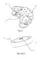
- FIG. 1illustrates an isometric exploded view of the posteriorly placed total lumbar artificial disc (“PPTLA”).
- PPTLAposteriorly placed total lumbar artificial disc
- FIG. 2illustrates an isometric view of the closed unexpanded PPLTA device.
- FIG. 3illustrates an isometric view of the PPLTA device with anterior plate expansion (extension).
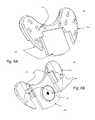
- FIGS. 4 A( 1 ) and 4 A( 2 )illustrate isometric and front views of the insertable core ball (Embodiment I).
- FIGS. 4 B( 1 ) and 4 B( 2 )illustrate exploded and cross-sectional views of an alternative ball/trough system (Embodiment II).
- FIGS. 5A , 5 B and 5 Cillustrate the components which act in unison to allow width and height device expansion. They include the bi-functional (height/width) adjustment (BFA) screw ( 5 A), the width adjustment screw ( 5 B), and the intervening slotted worm nut ( FIG. 5C ).
- BFAbi-functional (height/width) adjustment
- 5 Bwidth adjustment screw
- 5Cintervening slotted worm nut
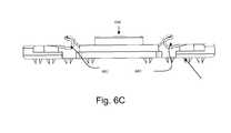
- FIGS. 6A and 6Billustrates the external ( FIG. 6A ), internal ( FIG. 6B ), and top ( FIG. 6 c ) views of the dorsal plate.
- FIGS. 7A and 7Billustrate the external ( FIG. 7A ) and internal ( FIG. 7B ) views of the ventral plate.
- FIG. 8illustrates an orthographic view of the uni-dimensional expanding artificial disc, embodiment I (UDEAD I).
- FIG. 9illustrates an exploded view of the artificial disc (UDEAD I)
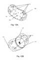
- FIGS. 10A and 10Billustrate the external and internal views of the external plates of the artificial disc (UDEAD I)
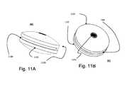
- FIGS. 11A and 11Billustrate the side and orthographic views of the ball of the artificial disc UDEAD I).
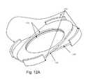
- FIGS. 12A and 12Billustrate the orthographic and exploded views of the ball limiters (UDEAD I)
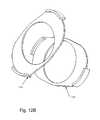
- FIG. 13illustrates the ball with the limiters (UDEAD I)
- FIG. 14illustrates a sample position of the entire artificial disc and how the ball limiters affect range of motion (UDEAD I)
- FIGS. 15 A, B, and Cillustrate the orthographic, frontal and exploded views of yet another embodiment of the UDEAD (embodiment II) which employs a ball with raised edges instead of ball limiters.
- FIGS. 16A and 16Billustrate side and orthographic views of the ball employed in UDEAD II.
- FIGS. 17A and 17Billustrate cross-sections of UDEAD (embodiment II) during lateral bending and flexion/extension.
- FIGS. 18A , 18 B and 18 Cillustrate the front, back and exploded views of the external insertion device used for UDEAD embodiments I and II.
- FIGS. 19A and 19Billustrate a detailed view of the plate insertion section of the external insertion device and the motion of the wedged separator expanding the disc plates.
- the above described problemscan be solved in the lumbar spine by the posterior insertion of a closed PPLTAD in the discs space after the performance of a discectomy. After insertion it is expanded in height (the anterior-posterior direction in a standing patient), and in width (disc space height in a standing patient).
- FIG. 1illustrates an isometric exploded view of the PPLTAD. It consists of two opposing plates 101 , 102 which are preferably titanium or cobalt chromium, each of which is comprised of a dorsal component 101 a, 102 a and ventral component 101 b, 102 b. Sandwiched in between the opposing plates 101 , 102 is a removable ball 103 which contacts a trough 104 on the inner aspects of both opposing plates.
- the mechanical crux to the PPLTAD height and width expandabilityare based on the interaction of a bi-functional (height/width) adjustment (BFA) screw 105 with a slotted worm nut 106 , and a width adjustment screw 107 and their unified interactions with the dorsal and ventral aspects of each the opposing plates 101 , 102 , and with their unified interaction with both opposing plates 101 , 102 .
- BFAbi-functional (height/width) adjustment
- a series of obliquely oriented spikes 108Located on the outer aspects of the plates 101 , 102 are a series of obliquely oriented spikes 108 .
- the obliqueness of the spikes 108hinders extrusion by orientation as well as by traction. We believe that this is a unique design which is not found in other prosthetic disc devices.
- FIG. 2illustrates the PPLTAD in its closed position prior to its insertion into the empty disc space.
- FIG. 3illustrates the PPLTAD with an extended (expanded) ventral plate 102 b.
- FIGS. 4 A( 1 ) and 4 A( 2 )illustrate isometric and frontal views respectively of the ball insert 103 (Embodiment I). It consists of an ellipsoid core 401 surrounded by a raised edge 402 . Upon its insertion into the PPLTAD when both surfaces of the ball 103 contact the troughs 104 of the opposing plates 101 , 102 and moves within them, the raised edge 402 prevents ball extrusion with patient movement.
- FIGS. 4 B( 1 ) and 4 B( 2 )illustrate a different ball/trough embodiment (II).
- this embodimentit is the ensconcing trough protrusions 404 surrounding the ball 403 and ball overhangs 405 which prevent ball extrusion as opposed to the ball rim (Embodiment I) preventing ball extrusion.
- Thispreferably allows for the same degree of lateral flexion and rotation as Embodiment I.
- FIGS. 5A , 5 B and 5 Cillustrate close up views of the key components of the expansile mechanism.
- FIG. 5Aillustrates a close-up of the bi-functional (height/width) adjustment (BFA) screw 105 . It is composed of a screw body 501 with threads 502 , a hex slot 503 , a neck 504 and a collar 505 . This screw 105 is inserted into the open bearings 601 of the inner aspect dorsal plate 102 a ( FIGS. 6B and 6C ) and the height adjustment threaded nut 704 and slot 703 of the inner aspect of the ventral plate 102 b ( FIG. 7B ).
- BFAbi-functional (height/width) adjustment
- the BFA threads 502 of screw 105are in direct contact with the external slots 509 of the slotted worm nut 106 ( FIG. 5B , and FIG. 1 ).
- the slotted worm nut 106in turn has internal threadings 506 ( FIG. 5B ) which accommodate the external threading 507 of the width adjustment screw 107 ( FIG. 5C , FIG. 1 ).
- the countersunk head 510 of the width adjustment screw 107 ( FIG. 5C ), and the head of the slotted worm nut 106fit into corresponding slots 602 on the inner aspect of the opposing dorsal plates 102 a ( FIG. 6B )
- FIGS. 6A , 6 B, 6 C, 7 A and 7 Billustrate a variety of views of the dorsal and ventral plates 102 a, 102 b. They illustrate their interrelationship, and their connectivity.
- the external view of the dorsal plate 102 a(FIG. 6 A)illustrates a large mid-line flange, and positioning flanges 603 on its left and right, which insert into the ventral plate slots 701 for the dorsal flanges ( FIG. 7A ).
- FIG. 6Billustrates the internal aspect of the dorsal plate 102 a. This has the trough 104 in a fixed position, and the open bearings 601 for insertion of the BFA screws 105 .
- FIG. 6Cis a top view of the dorsal plate 102 a illustrating the open bearings 601 for the BFA screws 105 , the spikes 108 and the trough 104 .
- FIG. 7Billustrates the threaded nuts 704 into which the BFA screws 105 are inserted as well as their slots 703 which the bottom aspect of the BFA screws 105 rest upon.
- Another possible embodiment of the opposing platesincludes making the opposing plates different sizes, and decreasing the sizes of the screws, thus allowing even more lateral flexion.
- the closed PPLTADis inserted into the emptied disc space ( FIG. 2 ).
- the heightis expanded by turning each of the four BFA screws 105 ( FIG. 1 ).
- These screws 105by virtue of being inserted into the height adjustment threaded nuts 704 of screws of the ventral plate 102 b ( FIG. 7B ), and the open bearings 601 of the dorsal plate 102 a (FIG. 6 C),allow graded sliding of the ventral plate slots 703 vis-a-vis the dorsal plate flanges 603 hence achieving graded separation from each other, i.e. height expansion ( FIGS. 1 , 3 , 6 A and 7 A).
- the inner ball core 401may interact with the inner troughs 104 and achieve complete and unhindered flexibility of motion.
- Different sized ball inserts 401accommodate for differences in disc space height.
- the method of posterior insertion of the PPLTAD into the posterior interspacecan be performed open microscopically, or closed tubularly, using endoscopic and/or fluoroscopic guidance.
- the patientAfter the adequate induction of anesthesia the patient is positioned in the prone position. A midline incision is made, bilateral lamina are exposed, and bilateral hemi-laminotomies are performed preserving bilateral facet joints so as not to incur instability.
- a complete discectomyis performed and the superior and inferior endplates exposed.
- the closed PPTLA without the core ball 401is inserted.
- the four BFA screws 105are turned clockwise leading to height extension of the opposing plates 101 , 102 via downward sliding of the ventral segments 101 b, 102 b of the plates.
- the screws 105are turned further clockwise thereby turning the width adjustment screws 107 via the turning of the slotted worm nut 106 . This drives the opposing plates 101 , 102 with their outer plate spikes 108 into the ventral endplates securing their attachment to the vertebral endplates.
- Fluoroscopic guidanceis used to verify placement of the troughs 104 of the inner aspect of the plates 101 , 102 at the center of the endplates so that they are at the center of gravity.
- the BFA screwsare turned counterclockwise, thereby disengaging from the plates 101 , 102 and the worm nuts 106 .
- the BFA screws 105are removed from their slots, and the slotted worm nuts 106 and widening screws 107 are disengaged from their inserts.
- the size between the opposing troughs 104is measured, and a custom-sized ball 401 is now inserted in between the troughs 104 .
- the size of the ball 401is such that it will fit substantially perfectly, and hence not dislodge.
- the patientis now closed in routine manner.
- This device and method of insertionoffer safe posterior lumbar placement with equal motion preservation compared to anteriorly placed lumbar discs.
- This PPLTADcan also be adopted for anterior lumbar placement, and for posterior and anterior placement into thoracic disc interspaces.
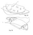
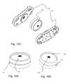
- FIGS. 8-19the above described problems can also be solved by inserting a total artificial disc 800 which consists of three separate components; two opposing bean shaped plates 801 , 802 and an interposing ball 803 which has ball limiters 804 which prevent ball extrusion (embodiment I), or raised edges which prevent extrusion (embodiment II).
- FIGS. 8 and 9illustrate orthographic and exploded views of the artificial disc 800 (embodiment I).
- FIGS. 15A-Cillustrate the orthographic, frontal and exploded views of Embodiment II.
- FIGS. 16A and Billustrate the side and orthogonal views of the ball of embodiment II.
- FIG. 10Aillustrates the external view of either the superior or interior plates 801 , 802 (embodiments I and II).
- the plate 801On the external surface of the plate 801 there are three types of spikes 808 to facilitate penetration and integration into the vertebral endplates.
- Around the peripheral edge of the plate 801are multiple pyramidal spikes 808 c.
- Surrounding the conical spikeare right angled lateral spikes 808 b.
- Each of the three types of spikes 808is designed to facilitate penetration contoured to the shape of the plate 801 with respect to the vertebral endplate. We are not aware of any other artificial disc designs which have this feature.
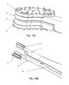
- the alignment slots 805which align with an external insertion/spreading device 1500 ( FIGS. 18-19 ).
- FIG. 10Billustrates the internal view of the superior or inferior plate 801 .
- a trough 806Centrally located is a trough 806 which will interact with the ball 803 of this ball/trough designed artificial disc.
- radial grooves 807At the center of the trough 806 are radial grooves 807 which interact with similar radial grooves 1100 of the ball 803 ( FIG. 11B 15 C) facilitating ball/trough contact.
- FIGS. 11A and 11Billustrate the ball 803 design (embodiment I) It has superior and inferior domes 1102 , 1103 . In between the domes 1102 , 1103 is a groove 1100 for the ball limiters 804 . The ball limiter 804 inserts into the ball groove 1100 ( FIGS. 11 and 13 ).
- FIG. 12illustrates that the ball limiter 804 is composed of superior and inferior leaflets 1201 , 1202 . At the periphery of these leaflets 1201 , 1202 there are raised barriers 1203 which limit ball motion and extrusion. After the plates 801 , 802 are inserted, when the ball 803 and limiters 804 are introduced, the superior and inferior leaflets 1201 , 1202 are aligned with each other.
- the inferior leaflet 1201preferably includes a ball groove insertion ring 1204 .
- the ball limiters 804are rotated such they are at approx 45-90 degrees angled with respect to each other ( FIG. 12A and 13 ).
- FIG. 14illustrates a sample position of the artificial disc 800 . It should be noted that with flexion and translation of the device 800 , the raised barriers 1203 of the ball limiters 804 are in contact with the superior and inferior plates 801 , 802 thereby limiting unrestrained motion of the ball 803 , and prevents ball extrusion.
- FIGS. 15 A, B and Cillustrate orthographic, frontal and exploded views of embodiment II.
- a ball 1503is disposed between superior plate 181 and inferior plate 802 .
- FIGS. 16A and 16Billustrate the side and orthographic views of the ball of UDEAD (embodiment II).
- the ball 1503preferably includes a groove 1507 for radiographic material, superior dome 1506 , and inferior dome (not shown).
- the ball 1503also includes superior raised edge 1504 , inferior raised edge 1505 and radial grooves 1508 . This ball has raised edges instead of limiters which prevent its extrusion and unrestrained motion.
- FIGS. 17A and 17Billustrate the motion of the ball insert during lateral bending, and flexion/extension.
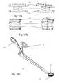
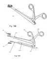
- FIGS. 18A , 18 B, 18 C, 19 A and 19 Billustrate the insertion device 1800 .
- the superior separator 1801 and inferior separator 1802( FIGS. 18C and 19 A and B) have extensions which are shaped exactly like the artificial disc plates 801 , 802 and their cradles fit into the alignment slots 805 of the plates 801 , 802 ( FIGS. 10A and B and 19 A and B).
- the lateral manipulator 1804 and medial manipulator 1803FIG. 18A-19 A and B) when opened lead to superior plate 801 and inferior plate 802 separation, and cause substantially parallel alignment of superior and inferior plate 801 , 802 penetration into opposing vertebral bodies.
- the medial and lateral manipulators 1803 , 1804are attached by a transmission linkage 1805 ( FIG. 18C ).
- the patientis positioned prone on a fluoroscopically amenable table.
- a unilateral hemi-laminotomyis performed.
- the procedurecan be performed microscopically, endoscopically or tubularly in routine manner.
- a routine discectomyis performed.
- the superior and inferior disc plates alignment slots 805are inserted into the cradles of the insertion device 1800 .
- the nerve rootis gently retracted and the disc plates 801 , 802 are inserted into the disc space attached to the inserting/spreading device 1800 .
- the plates 801 , 802are then placed at the center of gravity of the vertebral plates i.e. at the anterior—posterior and dorsal-ventral centers.
- the surgeonspreads the spreader 1800 which drives the wedge 1806 between the separators 1801 , 1802 ( FIG. 10 ) until the plates 801 , 802 have penetrated and incorporated into the superior and inferior vertebral bodies.
- the inserter/spreader 1500is then removed.
- the opposing plates 801 , 802are now substantially perfectly opposed to each other.
- the distance between the superior and inferior troughs 806are now measured, and the surgeon selects from a selection of balls 803 of different heights to fit between the plates 801 , 802 , depending on patient size, etc.
- the ball 803 with the ball limiters 804(embodiment I), or the ball with raised edges (embodiment II) are inserted in-between the superior and inferior troughs 806 .
- the superior and inferior leaflets 1202 , 1201 of the limiters 804are aligned with each other.
- the superior and inferior leaflets 1202 , 1201 using a forcepsare separated to effectively prevent ball extrusion and prevent completely unrestrained motion.
- the correct sized ballis simply inserted in between the two plates. The wound is then closed routinely.
- the current devicecan easily be adapted for placement in cervical and thoracic discs. It may also be suitable for multiple level placements. This current device enables the restoration of motion of diseased discs with minimal anatomical destruction and invasiveness, and avoids the serious complications of anteriorly placed discs. Furthermore when an anteriorly placed lumbar disc is removed, it is extremely technically challenging. Furthermore the artificial disc is then replaced by a fusion device limiting motion. The posterior unilateral placement of this device obviates all the above mentioned risks. The device presented here is safely implanted avoiding anterior vascular structures and nerves which control ejaculation. It is also easily and safely explanted if necessary. The ease and safety of the insertion of this device heralds in a new era of safe and simple artificial lumbar disc technology.
Landscapes
- Health & Medical Sciences (AREA)
- Engineering & Computer Science (AREA)
- Biomedical Technology (AREA)
- Orthopedic Medicine & Surgery (AREA)
- Transplantation (AREA)
- Neurology (AREA)
- Oral & Maxillofacial Surgery (AREA)
- Cardiology (AREA)
- Heart & Thoracic Surgery (AREA)
- Vascular Medicine (AREA)
- Life Sciences & Earth Sciences (AREA)
- Animal Behavior & Ethology (AREA)
- General Health & Medical Sciences (AREA)
- Public Health (AREA)
- Veterinary Medicine (AREA)
- Physical Education & Sports Medicine (AREA)
- Prostheses (AREA)
Abstract
Description
Claims (23)
Priority Applications (14)
| Application Number | Priority Date | Filing Date | Title |
|---|---|---|---|
| US11/487,415US7854766B2 (en) | 2004-05-13 | 2006-07-17 | Artificial total lumbar disc for unilateral safe and simple posterior placement in the lumbar spine, and removable bifunctional screw which drives vertical sliding expansile plate expansion, and interplate widening, and angled traction spikes |
| PCT/US2007/005005WO2007130198A2 (en) | 2006-04-04 | 2007-02-28 | Artificial disc for posterior placement in the lumbar spine |
| US12/889,328US10130493B2 (en) | 2006-04-04 | 2010-09-23 | Artificial total lumbar disc for unilateral safe and simple posterior placement in the lumbar spine, and removeable bifunctional screw which drives vertical sliding expansile plate expansion, and interplate widening, and angled traction spikes |
| US13/893,326US9056018B2 (en) | 2004-05-13 | 2013-05-13 | Artificial cervical and lumbar discs, disc plate insertion gun for performing sequential single plate intervertebral implantation enabling symmetric bi-disc plate alignment for interplate mobile core placement |
| US14/739,327US9867712B2 (en) | 2004-05-13 | 2015-06-15 | Artificial cervical and lumbar discs, disc plate insertion gun for performing sequential single plate intervertebral implantation enabling symmetric bi-disc plate alignment for interplate mobile core placement |
| US15/870,406US10610371B2 (en) | 2004-05-13 | 2018-01-12 | Artificial cervical and lumbar discs, disc plate insertion gun for performing sequential single plate intervertebral implantation enabling symmetric bi-disc plate alignment for interplate mobile core placement |
| US15/944,221US10376376B2 (en) | 2004-05-13 | 2018-04-03 | Artificial cervical and lumbar discs, disc plate insertion gun for performing sequential single plate intervertebral implantation enabling symmetric bi-disc plate alignment for interplate mobile core placement |
| US16/018,798US10369003B2 (en) | 2004-05-13 | 2018-06-26 | Artificial cervical and lumbar discs, disc plate insertion gun for performing sequential single plate intervertebral implantation enabling symmetric bi-disc plate alignment for interplate mobile core placement |
| US16/194,976US11135072B2 (en) | 2006-04-04 | 2018-11-19 | Artificial disc system |
| US16/841,355US11478359B2 (en) | 2004-05-13 | 2020-04-06 | Artificial disc system |
| US17/129,149US11083591B2 (en) | 2004-05-13 | 2020-12-21 | Artificial cervical and lumbar disc system |
| US17/393,672US11806244B2 (en) | 2004-05-13 | 2021-08-04 | Artificial cervical and lumbar disc system |
| US17/487,360US11771567B2 (en) | 2006-04-04 | 2021-09-28 | Artificial disc system |
| US17/681,231US11452619B2 (en) | 2006-04-04 | 2022-02-25 | Artificial disc system |
Applications Claiming Priority (9)
| Application Number | Priority Date | Filing Date | Title |
|---|---|---|---|
| US57009804P | 2004-05-13 | 2004-05-13 | |
| US57083704P | 2004-05-14 | 2004-05-14 | |
| US57246804P | 2004-05-20 | 2004-05-20 | |
| US57334604P | 2004-05-24 | 2004-05-24 | |
| US57831904P | 2004-06-10 | 2004-06-10 | |
| US10/964,633US20050256576A1 (en) | 2004-05-13 | 2004-10-15 | Artificial expansile total lumbar and thoracic discs for posterior placement without supplemental instrumentation and its adaptation for anterior placement of artificial cervical, thoracic and lumbar discs |
| US11/019,351US7083650B2 (en) | 2004-05-13 | 2004-12-23 | Artificial expansile total lumbar and thoracic discs for posterior placement without supplemental instrumentation and its adaptation for anterior placement of artificial cervical, thoracic and lumbar discs |
| US78872006P | 2006-04-04 | 2006-04-04 | |
| US11/487,415US7854766B2 (en) | 2004-05-13 | 2006-07-17 | Artificial total lumbar disc for unilateral safe and simple posterior placement in the lumbar spine, and removable bifunctional screw which drives vertical sliding expansile plate expansion, and interplate widening, and angled traction spikes |
Related Parent Applications (2)
| Application Number | Title | Priority Date | Filing Date |
|---|---|---|---|
| US10/964,633ContinuationUS20050256576A1 (en) | 2004-05-12 | 2004-10-15 | Artificial expansile total lumbar and thoracic discs for posterior placement without supplemental instrumentation and its adaptation for anterior placement of artificial cervical, thoracic and lumbar discs |
| US11/019,351Continuation-In-PartUS7083650B2 (en) | 2004-05-12 | 2004-12-23 | Artificial expansile total lumbar and thoracic discs for posterior placement without supplemental instrumentation and its adaptation for anterior placement of artificial cervical, thoracic and lumbar discs |
Related Child Applications (3)
| Application Number | Title | Priority Date | Filing Date |
|---|---|---|---|
| US10/964,633Continuation-In-PartUS20050256576A1 (en) | 2004-05-12 | 2004-10-15 | Artificial expansile total lumbar and thoracic discs for posterior placement without supplemental instrumentation and its adaptation for anterior placement of artificial cervical, thoracic and lumbar discs |
| US11/943,334Continuation-In-PartUS8535379B2 (en) | 2004-05-13 | 2007-11-20 | Artificial cervical and lumbar discs, disc plate insertion gun for performing sequential single plate intervertebral implantation enabling symmetric bi-disc plate alignment for interplate mobile core placement |
| US12/889,328DivisionUS10130493B2 (en) | 2006-04-04 | 2010-09-23 | Artificial total lumbar disc for unilateral safe and simple posterior placement in the lumbar spine, and removeable bifunctional screw which drives vertical sliding expansile plate expansion, and interplate widening, and angled traction spikes |
Publications (2)
| Publication Number | Publication Date |
|---|---|
| US20070198089A1 US20070198089A1 (en) | 2007-08-23 |
| US7854766B2true US7854766B2 (en) | 2010-12-21 |
Family
ID=38668204
Family Applications (5)
| Application Number | Title | Priority Date | Filing Date |
|---|---|---|---|
| US11/487,415Expired - Fee RelatedUS7854766B2 (en) | 2004-05-13 | 2006-07-17 | Artificial total lumbar disc for unilateral safe and simple posterior placement in the lumbar spine, and removable bifunctional screw which drives vertical sliding expansile plate expansion, and interplate widening, and angled traction spikes |
| US12/889,328ActiveUS10130493B2 (en) | 2006-04-04 | 2010-09-23 | Artificial total lumbar disc for unilateral safe and simple posterior placement in the lumbar spine, and removeable bifunctional screw which drives vertical sliding expansile plate expansion, and interplate widening, and angled traction spikes |
| US16/194,976Active2027-04-11US11135072B2 (en) | 2006-04-04 | 2018-11-19 | Artificial disc system |
| US17/487,360ActiveUS11771567B2 (en) | 2006-04-04 | 2021-09-28 | Artificial disc system |
| US17/681,231ActiveUS11452619B2 (en) | 2006-04-04 | 2022-02-25 | Artificial disc system |
Family Applications After (4)
| Application Number | Title | Priority Date | Filing Date |
|---|---|---|---|
| US12/889,328ActiveUS10130493B2 (en) | 2006-04-04 | 2010-09-23 | Artificial total lumbar disc for unilateral safe and simple posterior placement in the lumbar spine, and removeable bifunctional screw which drives vertical sliding expansile plate expansion, and interplate widening, and angled traction spikes |
| US16/194,976Active2027-04-11US11135072B2 (en) | 2006-04-04 | 2018-11-19 | Artificial disc system |
| US17/487,360ActiveUS11771567B2 (en) | 2006-04-04 | 2021-09-28 | Artificial disc system |
| US17/681,231ActiveUS11452619B2 (en) | 2006-04-04 | 2022-02-25 | Artificial disc system |
Country Status (2)
| Country | Link |
|---|---|
| US (5) | US7854766B2 (en) |
| WO (1) | WO2007130198A2 (en) |
Cited By (69)
| Publication number | Priority date | Publication date | Assignee | Title |
|---|---|---|---|---|
| US20110130835A1 (en)* | 2008-12-10 | 2011-06-02 | Innvotec Surgical, Inc. | Adjustable Distraction Cage With Linked Locking Mechanisms |
| US20120059471A1 (en)* | 2004-09-23 | 2012-03-08 | Cervitech, Inc. | Prosthesis for partial replacement of a vertebral body |
| US20120296433A1 (en)* | 2010-02-02 | 2012-11-22 | Azadeh Farin | Spine surgery device |
| US8394143B2 (en) | 2005-09-26 | 2013-03-12 | Coalign Innovations, Inc. | Selectively expanding spine cage, hydraulically controllable in three dimensions for enhanced spinal fusion |
| US8435296B2 (en) | 2008-02-22 | 2013-05-07 | Coalign Innovations, Inc. | Hydraulically actuated expanding spine cage with extendable locking anchor |
| US8444697B1 (en)* | 2010-11-18 | 2013-05-21 | Daniel Butler | Spinal fusion implant and methods of use thereof |
| US8480741B2 (en) | 2005-09-26 | 2013-07-09 | Coalign Innovations, Inc. | Selectively expanding spine cage, hydraulically controllable in three dimensions for vertebral body replacement |
| US20130253650A1 (en)* | 2008-12-10 | 2013-09-26 | Coalign Innovations, Inc. | Adjustable Distraction Cage With Linked Locking Mechanisms |
| US20130261631A1 (en)* | 2012-03-29 | 2013-10-03 | Marc E. Ruhling | Orthopaedic surgical instrument for knee surgery |
| US8932355B2 (en) | 2008-02-22 | 2015-01-13 | Coalign Innovations, Inc. | Spinal implant with expandable fixation |
| US9028550B2 (en) | 2005-09-26 | 2015-05-12 | Coalign Innovations, Inc. | Selectively expanding spine cage with enhanced bone graft infusion |
| US9198765B1 (en) | 2011-10-31 | 2015-12-01 | Nuvasive, Inc. | Expandable spinal fusion implants and related methods |
| US9295562B2 (en) | 2008-01-17 | 2016-03-29 | DePuy Synthes Products, Inc. | Expandable intervertebral implant and associated method of manufacturing the same |
| US9320615B2 (en) | 2010-06-29 | 2016-04-26 | DePuy Synthes Products, Inc. | Distractible intervertebral implant |
| US9402737B2 (en) | 2007-06-26 | 2016-08-02 | DePuy Synthes Products, Inc. | Highly lordosed fusion cage |
| US9414934B2 (en) | 2008-04-05 | 2016-08-16 | DePuy Synthes Products, Inc. | Expandable intervertebral implant |
| US9445918B1 (en) | 2012-10-22 | 2016-09-20 | Nuvasive, Inc. | Expandable spinal fusion implants and related instruments and methods |
| US9526620B2 (en) | 2009-03-30 | 2016-12-27 | DePuy Synthes Products, Inc. | Zero profile spinal fusion cage |
| US9561117B2 (en) | 2012-07-26 | 2017-02-07 | DePuy Synthes Products, Inc. | Expandable implant |
| US9717601B2 (en) | 2013-02-28 | 2017-08-01 | DePuy Synthes Products, Inc. | Expandable intervertebral implant, system, kit and method |
| US9724207B2 (en) | 2003-02-14 | 2017-08-08 | DePuy Synthes Products, Inc. | In-situ formed intervertebral fusion device and method |
| US9750552B2 (en) | 2009-07-06 | 2017-09-05 | DePuy Synthes Products, Inc. | Expandable fixation assemblies |
| US9750618B1 (en) | 2016-11-29 | 2017-09-05 | Amendia, Inc. | Intervertebral implant device with independent distal-proximal expansion |
| US9795493B1 (en) | 2013-03-15 | 2017-10-24 | Nuvasive, Inc. | Expandable intervertebral implant and methods of use thereof |
| US9833334B2 (en) | 2010-06-24 | 2017-12-05 | DePuy Synthes Products, Inc. | Enhanced cage insertion assembly |
| US9913727B2 (en) | 2015-07-02 | 2018-03-13 | Medos International Sarl | Expandable implant |
| US9949769B2 (en) | 2004-03-06 | 2018-04-24 | DePuy Synthes Products, Inc. | Dynamized interspinal implant |
| US9993349B2 (en) | 2002-06-27 | 2018-06-12 | DePuy Synthes Products, Inc. | Intervertebral disc |
| US10159582B2 (en) | 2011-09-16 | 2018-12-25 | DePuy Synthes Products, Inc. | Removable, bone-securing cover plate for intervertebral fusion cage |
| US10369015B2 (en) | 2010-09-23 | 2019-08-06 | DePuy Synthes Products, Inc. | Implant inserter having a laterally-extending dovetail engagement feature |
| US10390963B2 (en) | 2006-12-07 | 2019-08-27 | DePuy Synthes Products, Inc. | Intervertebral implant |
| US10398563B2 (en) | 2017-05-08 | 2019-09-03 | Medos International Sarl | Expandable cage |
| US10433974B2 (en) | 2003-06-30 | 2019-10-08 | DePuy Synthes Products, Inc. | Intervertebral implant with conformable endplate |
| US10470891B2 (en) | 2016-09-12 | 2019-11-12 | Howmedica Osteonics Corp. | Interbody implant with independent control of expansion at multiple locations |
| CN110494102A (en)* | 2017-04-04 | 2019-11-22 | 罗伯特·B·齐奥巴 | For restoring the mobile cage system of spinal motion ability |
| US10485675B2 (en) | 2016-10-26 | 2019-11-26 | Howmedica Osteonics Corp. | Expandable interbody implant with lateral articulation |
| US10500062B2 (en) | 2009-12-10 | 2019-12-10 | DePuy Synthes Products, Inc. | Bellows-like expandable interbody fusion cage |
| US10537436B2 (en) | 2016-11-01 | 2020-01-21 | DePuy Synthes Products, Inc. | Curved expandable cage |
| US10548738B2 (en) | 2016-04-07 | 2020-02-04 | Howmedica Osteonics Corp. | Expandable interbody implant |
| US10729553B2 (en) | 2017-09-15 | 2020-08-04 | Stryker European Operations Holdings Llc | Intervertebral body fusion device expanded with hardening material |
| US10888433B2 (en) | 2016-12-14 | 2021-01-12 | DePuy Synthes Products, Inc. | Intervertebral implant inserter and related methods |
| US10940018B2 (en) | 2016-05-20 | 2021-03-09 | Howmedica Osteonics Corp. | Expandable interbody implant with lordosis correction |
| US10940016B2 (en) | 2017-07-05 | 2021-03-09 | Medos International Sarl | Expandable intervertebral fusion cage |
| US11116642B2 (en) | 2009-11-25 | 2021-09-14 | Moskowitz Family Llc | Total artificial spino-laminar prosthetic replacement |
| US11337825B2 (en) | 2020-05-15 | 2022-05-24 | Life Spine, Inc. | Steerable implant assembly |
| US11344424B2 (en) | 2017-06-14 | 2022-05-31 | Medos International Sarl | Expandable intervertebral implant and related methods |
| US11382764B2 (en) | 2019-06-10 | 2022-07-12 | Life Spine, Inc. | Expandable implant assembly with compression features |
| US11426286B2 (en) | 2020-03-06 | 2022-08-30 | Eit Emerging Implant Technologies Gmbh | Expandable intervertebral implant |
| US11426290B2 (en) | 2015-03-06 | 2022-08-30 | DePuy Synthes Products, Inc. | Expandable intervertebral implant, system, kit and method |
| US11446156B2 (en) | 2018-10-25 | 2022-09-20 | Medos International Sarl | Expandable intervertebral implant, inserter instrument, and related methods |
| US11452607B2 (en) | 2010-10-11 | 2022-09-27 | DePuy Synthes Products, Inc. | Expandable interspinous process spacer implant |
| US11497619B2 (en) | 2013-03-07 | 2022-11-15 | DePuy Synthes Products, Inc. | Intervertebral implant |
| US11510788B2 (en) | 2016-06-28 | 2022-11-29 | Eit Emerging Implant Technologies Gmbh | Expandable, angularly adjustable intervertebral cages |
| US11554020B2 (en) | 2020-09-08 | 2023-01-17 | Life Spine, Inc. | Expandable implant with pivoting control assembly |
| US11596523B2 (en) | 2016-06-28 | 2023-03-07 | Eit Emerging Implant Technologies Gmbh | Expandable and angularly adjustable articulating intervertebral cages |
| US11602440B2 (en) | 2020-06-25 | 2023-03-14 | Life Spine, Inc. | Expandable implant assembly |
| US11602439B2 (en) | 2020-04-16 | 2023-03-14 | Life Spine, Inc. | Expandable implant assembly |
| US11752009B2 (en) | 2021-04-06 | 2023-09-12 | Medos International Sarl | Expandable intervertebral fusion cage |
| US11850160B2 (en) | 2021-03-26 | 2023-12-26 | Medos International Sarl | Expandable lordotic intervertebral fusion cage |
| US11857432B2 (en) | 2020-04-13 | 2024-01-02 | Life Spine, Inc. | Expandable implant assembly |
| US11896494B2 (en) | 2017-07-10 | 2024-02-13 | Life Spine, Inc. | Expandable implant assembly |
| US11911287B2 (en) | 2010-06-24 | 2024-02-27 | DePuy Synthes Products, Inc. | Lateral spondylolisthesis reduction cage |
| US11986398B2 (en) | 2013-03-13 | 2024-05-21 | Life Spine, Inc. | Expandable implant assembly |
| US12042395B2 (en) | 2019-06-11 | 2024-07-23 | Life Spine, Inc. | Expandable implant assembly |
| US12090064B2 (en) | 2022-03-01 | 2024-09-17 | Medos International Sarl | Stabilization members for expandable intervertebral implants, and related systems and methods |
| US12232975B2 (en) | 2008-02-22 | 2025-02-25 | Howmedica Osteonics Corp. | Lockable spinal implant |
| US12336917B2 (en) | 2020-05-15 | 2025-06-24 | Life Spine, Inc. | Steerable implant assembly |
| US12370058B2 (en) | 2022-04-05 | 2025-07-29 | Spine Wave, Inc. | Belt driven expandable interbody fusion device |
| US12440346B2 (en) | 2023-03-31 | 2025-10-14 | DePuy Synthes Products, Inc. | Expandable intervertebral implant |
Families Citing this family (55)
| Publication number | Priority date | Publication date | Assignee | Title |
|---|---|---|---|---|
| US6936071B1 (en) | 1999-07-02 | 2005-08-30 | Spine Solutions, Inc. | Intervertebral implant |
| US7491204B2 (en) | 2003-04-28 | 2009-02-17 | Spine Solutions, Inc. | Instruments and method for preparing an intervertebral space for receiving an artificial disc implant |
| US11806244B2 (en) | 2004-05-13 | 2023-11-07 | Moskowitz Family Llc | Artificial cervical and lumbar disc system |
| US7854766B2 (en) | 2004-05-13 | 2010-12-21 | Moskowitz Nathan C | Artificial total lumbar disc for unilateral safe and simple posterior placement in the lumbar spine, and removable bifunctional screw which drives vertical sliding expansile plate expansion, and interplate widening, and angled traction spikes |
| US8535379B2 (en) | 2006-04-04 | 2013-09-17 | Nathan C. Moskowitz | Artificial cervical and lumbar discs, disc plate insertion gun for performing sequential single plate intervertebral implantation enabling symmetric bi-disc plate alignment for interplate mobile core placement |
| US9744052B2 (en) | 2005-04-12 | 2017-08-29 | Nathan C. Moskowitz | Bi-directional fixating/locking transvertebral body screw/intervertebral cage stand-alone constructs |
| US7846188B2 (en) | 2005-04-12 | 2010-12-07 | Moskowitz Nathan C | Bi-directional fixating transvertebral body screws, zero-profile horizontal intervertebral miniplates, total intervertebral body fusion devices, and posterior motion-calibrating interarticulating joint stapling device for spinal fusion |
| US7972363B2 (en) | 2005-04-12 | 2011-07-05 | Moskowitz Ahmnon D | Bi-directional fixating/locking transvertebral body screw/intervertebral cage stand-alone constructs and posterior cervical and lumbar interarticulating joint stapling guns and devices for spinal fusion |
| US7704279B2 (en) | 2005-04-12 | 2010-04-27 | Moskowitz Mosheh T | Bi-directional fixating transvertebral body screws, zero-profile horizontal intervertebral miniplates, expansile intervertebral body fusion devices, and posterior motion-calibrating interarticulating joint stapling device for spinal fusion |
| US11903849B2 (en) | 2005-04-12 | 2024-02-20 | Moskowitz Family Llc | Intervertebral implant and tool assembly |
| US7942903B2 (en) | 2005-04-12 | 2011-05-17 | Moskowitz Ahmnon D | Bi-directional fixating transvertebral body screws and posterior cervical and lumbar interarticulating joint calibrated stapling devices for spinal fusion |
| US9532821B2 (en) | 2005-04-12 | 2017-01-03 | Nathan C. Moskowitz | Bi-directional fixating/locking transvertebral body screw/intervertebral cage stand-alone constructs with vertical hemi-bracket screw locking mechanism |
| US9848993B2 (en) | 2005-04-12 | 2017-12-26 | Nathan C. Moskowitz | Zero-profile expandable intervertebral spacer devices for distraction and spinal fusion and a universal tool for their placement and expansion |
| US7854765B2 (en) | 2006-04-20 | 2010-12-21 | Moskowitz Mosheh T | Electronically controlled artificial intervertebral disc with motor assisted actuation systems |
| EP3628244A1 (en) | 2006-07-24 | 2020-04-01 | Centinel Spine Schweiz GmbH | Intervertebral implant with keel |
| BRPI0714955A2 (en) | 2006-07-31 | 2013-07-23 | Systhes Gmbh | instrument system and method for preparing an intervertebral space to receive an implant, and milling guide for use with an instrument system |
| US20080228275A1 (en)* | 2007-03-14 | 2008-09-18 | Heather Cannon | Intervertebral implant component with three points of contact |
| US7744649B2 (en)* | 2007-06-25 | 2010-06-29 | Moore Mark R | Spondylolisthesis correction apparatus and method |
| WO2009040840A1 (en)* | 2007-09-28 | 2009-04-02 | Sintea Biotech S.P.A. | Intersomatic cage, pliers for intersomatic cage, kit for insertion of an intersomatic cage |
| US8241331B2 (en)* | 2007-11-08 | 2012-08-14 | Spine21 Ltd. | Spinal implant having a post-operative adjustable dimension |
| US8172902B2 (en) | 2008-07-17 | 2012-05-08 | Spinemedica, Llc | Spinal interbody spacers |
| US8523944B2 (en) | 2008-12-31 | 2013-09-03 | Spinex Tec, Llc | Methods and apparatus for vertebral body distraction and fusion employing flexure members |
| US8628577B1 (en) | 2009-03-19 | 2014-01-14 | Ex Technology, Llc | Stable device for intervertebral distraction and fusion |
| WO2011011626A2 (en) | 2009-07-22 | 2011-01-27 | Spinex Tec, Llc | Coaxial screw gear sleeve mechanism |
| US8636746B2 (en) | 2009-12-31 | 2014-01-28 | Spinex Tec, Llc | Methods and apparatus for insertion of vertebral body distraction and fusion devices |
| US8353963B2 (en)* | 2010-01-12 | 2013-01-15 | Globus Medical | Expandable spacer and method for use thereof |
| US8900309B2 (en)* | 2010-08-31 | 2014-12-02 | Meditech Spine, Llc | Spinal implants |
| US8377140B2 (en) | 2011-01-12 | 2013-02-19 | Ebi, Llc | Expandable spinal implant device |
| US9308099B2 (en) | 2011-02-14 | 2016-04-12 | Imds Llc | Expandable intervertebral implants and instruments |
| WO2012112592A2 (en)* | 2011-02-14 | 2012-08-23 | Medicinelodge, Inc Dba Imds Co-Innovation | Expandable intervertebral spacer |
| US9066813B2 (en)* | 2011-06-03 | 2015-06-30 | Biomet Spine, Llc | Unidirectional dynamic interbody fusion device and method of use |
| WO2013052807A2 (en)* | 2011-10-05 | 2013-04-11 | H. Lee Moffitt Cancer Center And Research Institute, Inc. | Bone fusion system |
| US9271777B2 (en) | 2011-12-14 | 2016-03-01 | Biomet Spine, Llc | Unilateral moveable interbody fusion device and method of use |
| US20130261746A1 (en)* | 2012-03-28 | 2013-10-03 | Linares Medical Devices, Llc | Implantable inter-vertebral disk having upper and lower layers of a metal exhibiting bone fusing characteristics and which sandwich therebetween a soft plastic cushioning disc for providing dynamic properties mimicking that of a natural inter-vertebral disc |
| EP2948106B1 (en) | 2013-01-24 | 2021-05-26 | BioSpine, LLC | Adjustable interbody fusion device |
| US9980825B2 (en) | 2013-05-13 | 2018-05-29 | Biospine, Llc | Adjustable interbody fusion devices |
| US8940049B1 (en) | 2014-04-01 | 2015-01-27 | Ex Technology, Llc | Expandable intervertebral cage |
| US9486328B2 (en) | 2014-04-01 | 2016-11-08 | Ex Technology, Llc | Expandable intervertebral cage |
| US20180049754A1 (en)* | 2015-03-13 | 2018-02-22 | Redemed S.R.L. | Intervertebral prosthesis, apparatus for implanting intervertebral prostheses and surgical method for implanting intervertebral prostheses, particularly for percutaneous mini-invasive surgery procedures |
| JP6949006B2 (en) | 2015-08-25 | 2021-10-13 | アイエムディーエス リミテッド ライアビリティ カンパニー | Expandable facet implant |
| WO2018081322A1 (en) | 2016-10-25 | 2018-05-03 | Imds Llc | Methods and instrumentation for intervertebral cage expansion |
| US10945859B2 (en) | 2018-01-29 | 2021-03-16 | Amplify Surgical, Inc. | Expanding fusion cages |
| CN112055576B (en)* | 2018-05-01 | 2024-03-19 | I-佩戈有限公司 | spacer for vertebral surgery |
| US10722380B1 (en)* | 2019-02-04 | 2020-07-28 | Bret Michael Berry | Laterally expandable spinal implant |
| US11234835B2 (en) | 2019-03-05 | 2022-02-01 | Octagon Spine Llc | Transversely expandable minimally invasive intervertebral cage |
| US11497622B2 (en) | 2019-03-05 | 2022-11-15 | Ex Technology, Llc | Transversely expandable minimally invasive intervertebral cage and insertion and extraction device |
| GB201910668D0 (en)* | 2019-07-25 | 2019-09-11 | Axis Spine Tech Ltd | Assemblies for and methods of determing height and angle of an intervertebral device |
| KR102217719B1 (en) | 2020-04-14 | 2021-02-18 | 힐로 이노베이션 | Lumbar Intervertebral Artificial Disc and the method of the Lumbar Intervertebral Artificial Disc insertion |
| US11911282B2 (en)* | 2020-04-24 | 2024-02-27 | Warsaw Orthopedic, Inc. | Spinal implant system and method |
| US11583411B2 (en) | 2020-10-27 | 2023-02-21 | Loubert S. Suddaby | Expandable intervertebral fusion implant |
| WO2023055783A1 (en) | 2021-09-29 | 2023-04-06 | Ex Technology, Llc | Expandable intervertebral cage |
| US11896491B2 (en)* | 2021-10-19 | 2024-02-13 | Loubert S. Suddaby | Expandable total disc replacement implant |
| US12011365B2 (en) | 2022-07-18 | 2024-06-18 | Octagon Spine Llc | Transversely expandable minimally invasive inter vertebral cage |
| USD1084367S1 (en)* | 2023-05-17 | 2025-07-15 | Jiangsu Alphay Medical Device Co., Ltd | Lumbar device |
| USD1065557S1 (en)* | 2023-05-29 | 2025-03-04 | Jiangsu Alphay Medical Device Co., Ltd | Lumbar device |
Citations (36)
| Publication number | Priority date | Publication date | Assignee | Title |
|---|---|---|---|---|
| US4997432A (en) | 1988-03-23 | 1991-03-05 | Waldemar Link Gmbh & Co. | Surgical instrument set |
| US5123926A (en) | 1991-02-22 | 1992-06-23 | Madhavan Pisharodi | Artificial spinal prosthesis |
| US5514180A (en) | 1994-01-14 | 1996-05-07 | Heggeness; Michael H. | Prosthetic intervertebral devices |
| US5782832A (en) | 1996-10-01 | 1998-07-21 | Surgical Dynamics, Inc. | Spinal fusion implant and method of insertion thereof |
| US6126689A (en) | 1998-06-15 | 2000-10-03 | Expanding Concepts, L.L.C. | Collapsible and expandable interbody fusion device |
| US6368350B1 (en) | 1999-03-11 | 2002-04-09 | Sulzer Spine-Tech Inc. | Intervertebral disc prosthesis and method |
| US6375682B1 (en) | 2001-08-06 | 2002-04-23 | Lewis W. Fleischmann | Collapsible, rotatable and expandable spinal hydraulic prosthetic device |
| US6419704B1 (en) | 1999-10-08 | 2002-07-16 | Bret Ferree | Artificial intervertebral disc replacement methods and apparatus |
| US6458159B1 (en) | 2000-08-15 | 2002-10-01 | John S. Thalgott | Disc prosthesis |
| US6527804B1 (en) | 1998-12-11 | 2003-03-04 | Dimso (Distribution Medicale Du Sud-Quest) | Intervertebral disk prosthesis |
| US6533818B1 (en) | 2000-04-26 | 2003-03-18 | Pearl Technology Holdings, Llc | Artificial spinal disc |
| US6572653B1 (en) | 2001-12-07 | 2003-06-03 | Rush E. Simonson | Vertebral implant adapted for posterior insertion |
| US6579318B2 (en) | 2000-06-12 | 2003-06-17 | Ortho Development Corporation | Intervertebral spacer |
| US6582468B1 (en) | 1998-12-11 | 2003-06-24 | Spryker Spine | Intervertebral disc prosthesis with compressible body |
| US6610093B1 (en)* | 2000-07-28 | 2003-08-26 | Perumala Corporation | Method and apparatus for stabilizing adjacent vertebrae |
| US6641614B1 (en) | 1997-05-01 | 2003-11-04 | Spinal Concepts, Inc. | Multi-variable-height fusion device |
| US6719794B2 (en) | 2001-05-03 | 2004-04-13 | Synthes (U.S.A.) | Intervertebral implant for transforaminal posterior lumbar interbody fusion procedure |
| US6723126B1 (en) | 2002-11-01 | 2004-04-20 | Sdgi Holdings, Inc. | Laterally expandable cage |
| US6730088B2 (en)* | 2001-08-29 | 2004-05-04 | Chung-Chun Yeh | Device for fixing spinal column under treatment |
| US6733532B1 (en) | 1998-12-11 | 2004-05-11 | Stryker Spine | Intervertebral disc prosthesis with improved mechanical behavior |
| US6764491B2 (en) | 1999-10-21 | 2004-07-20 | Sdgi Holdings, Inc. | Devices and techniques for a posterior lateral disc space approach |
| US6770094B2 (en) | 2001-07-05 | 2004-08-03 | Gerald Fehling | Intervertebral disc prosthesis |
| US20040254644A1 (en)* | 2002-10-21 | 2004-12-16 | Taylor Brett Allison | Intervertebral disk prosthesis |
| US20050027362A1 (en) | 1999-02-26 | 2005-02-03 | Williams Lytton A. | Method and apparatus for intervertebral implant anchorage |
| US20050049590A1 (en) | 2003-03-07 | 2005-03-03 | Neville Alleyne | Spinal implant with securement spikes |
| US20050085910A1 (en)* | 2003-10-16 | 2005-04-21 | Sweeney Patrick J. | Vertebral prosthesis |
| US20050216084A1 (en) | 2003-04-22 | 2005-09-29 | Fleischmann Lewis W | Collapsible, rotatable, and tiltable hydraulic spinal disc prosthesis system with selectable modular components |
| US20050273174A1 (en)* | 2003-08-05 | 2005-12-08 | Gordon Charles R | Expandable articulating intervertebral implant with spacer |
| US20060036325A1 (en) | 2003-07-31 | 2006-02-16 | Globus Medical Inc. | Anterior prosthetic spinal disc replacement |
| US20060178745A1 (en)* | 2005-02-10 | 2006-08-10 | Depuy Spine, Inc. | Intervertebral prosthetic disc |
| US20060195192A1 (en) | 2003-08-05 | 2006-08-31 | Flexuspine, Inc. | Artificial functional spinal unit assemblies |
| US7115144B2 (en)* | 2004-03-02 | 2006-10-03 | Joint Synergy, Llc | Spinal implant |
| US7118580B1 (en)* | 1999-09-14 | 2006-10-10 | Spine Solutions Inc. | Instrument for inserting intervertebral implants |
| US20070055378A1 (en) | 2003-07-31 | 2007-03-08 | Ankney David W | Transforaminal prosthetic spinal disc replacement and methods thereof |
| US20070073400A1 (en) | 2003-12-29 | 2007-03-29 | Globus Medical, Inc. | Spinal fusion implant |
| US7250060B2 (en)* | 2004-01-27 | 2007-07-31 | Sdgi Holdings, Inc. | Hybrid intervertebral disc system |
Family Cites Families (65)
| Publication number | Priority date | Publication date | Assignee | Title |
|---|---|---|---|---|
| US200238A (en)* | 1878-02-12 | Improvement in blacksmiths tongs | ||
| US1553623A (en)* | 1924-08-20 | 1925-09-15 | Fred P Clark | Parallel valve-spring lifter |
| US2090872A (en)* | 1936-03-30 | 1937-08-24 | Paul A Lamb | Battery terminal puller |
| US2214985A (en)* | 1938-04-30 | 1940-09-17 | Bachmann Henry | Forceps |
| US4554914A (en) | 1983-10-04 | 1985-11-26 | Kapp John P | Prosthetic vertebral body |
| EP0176728B1 (en) | 1984-09-04 | 1989-07-26 | Humboldt-Universität zu Berlin | Intervertebral-disc prosthesis |
| US4636217A (en) | 1985-04-23 | 1987-01-13 | Regents Of The University Of Minnesota | Anterior spinal implant |
| US4960420A (en) | 1988-08-23 | 1990-10-02 | Marlowe Goble E | Channel ligament clamp and system |
| AR244071A1 (en) | 1991-09-05 | 1993-10-29 | Groiso Jorge Abel | An elastic staple for osteosynthesis and a tool for placing it. |
| DE4208116C2 (en) | 1992-03-13 | 1995-08-03 | Link Waldemar Gmbh Co | Intervertebral disc prosthesis |
| US6197056B1 (en)* | 1992-07-15 | 2001-03-06 | Ras Holding Corp. | Segmented scleral band for treatment of presbyopia and other eye disorders |
| US5584831A (en)* | 1993-07-09 | 1996-12-17 | September 28, Inc. | Spinal fixation device and method |
| US5667472A (en) | 1994-03-18 | 1997-09-16 | Clarus Medical Systems, Inc. | Surgical instrument and method for use with a viewing system |
| US6375882B1 (en) | 1996-11-27 | 2002-04-23 | E. I. Du Pont De Nemours And Company | Spinning machine and conversion process |
| US5951564A (en)* | 1996-12-18 | 1999-09-14 | Bristol-Myers Squibb Company | Orthopaedic positioning apparatus |
| US5960522A (en) | 1997-05-21 | 1999-10-05 | Micron Electronics, Inc. | Ribbon cable alligator clamp |
| US7030904B2 (en) | 1997-10-06 | 2006-04-18 | Micro-Medical Devices, Inc. | Reduced area imaging device incorporated within wireless endoscopic devices |
| AU760821B2 (en)* | 1998-10-02 | 2003-05-22 | Synthes Gmbh | Spinal disc space distractor |
| US6113637A (en) | 1998-10-22 | 2000-09-05 | Sofamor Danek Holdings, Inc. | Artificial intervertebral joint permitting translational and rotational motion |
| US6174311B1 (en)* | 1998-10-28 | 2001-01-16 | Sdgi Holdings, Inc. | Interbody fusion grafts and instrumentation |
| US6193757B1 (en) | 1998-10-29 | 2001-02-27 | Sdgi Holdings, Inc. | Expandable intervertebral spacers |
| DE19903762C1 (en)* | 1999-01-30 | 2000-11-16 | Aesculap Ag & Co Kg | Surgical instrument for inserting intervertebral implants |
| US6602185B1 (en) | 1999-02-18 | 2003-08-05 | Olympus Optical Co., Ltd. | Remote surgery support system |
| US6866682B1 (en) | 1999-09-02 | 2005-03-15 | Stryker Spine | Distractable corpectomy device |
| US7037258B2 (en) | 1999-09-24 | 2006-05-02 | Karl Storz Imaging, Inc. | Image orientation for endoscopic video displays |
| US6436101B1 (en)* | 1999-10-13 | 2002-08-20 | James S. Hamada | Rasp for use in spine surgery |
| IL143260A (en) | 2001-05-20 | 2006-09-05 | Given Imaging Ltd | Array system and method for locating an in vivo signal source |
| US6556470B1 (en) | 2001-07-31 | 2003-04-29 | Hewlett-Packard Company | Field addressable rewritable media |
| US6835173B2 (en) | 2001-10-05 | 2004-12-28 | Scimed Life Systems, Inc. | Robotic endoscope |
| US7169153B2 (en)* | 2002-06-10 | 2007-01-30 | Depuy Spine | Surgical instrument for inserting intervertebral prosthesis |
| US7018415B1 (en) | 2002-09-23 | 2006-03-28 | Sdgi Holdings, Inc. | Expandable spinal fusion device and methods of promoting spinal fusion |
| US6899735B2 (en) | 2002-10-02 | 2005-05-31 | Sdgi Holdings, Inc. | Modular intervertebral prosthesis system |
| JP4290407B2 (en) | 2002-10-28 | 2009-07-08 | パナソニック株式会社 | Electronics |
| US20040133278A1 (en)* | 2002-10-31 | 2004-07-08 | Marino James F. | Spinal disc implant |
| FR2846550B1 (en) | 2002-11-05 | 2006-01-13 | Ldr Medical | INTERVERTEBRAL DISC PROSTHESIS |
| US6908484B2 (en) | 2003-03-06 | 2005-06-21 | Spinecore, Inc. | Cervical disc replacement |
| US7188439B2 (en) | 2003-03-10 | 2007-03-13 | Adidas International Marketing B.V. | Intelligent footwear systems |
| US6981989B1 (en) | 2003-04-22 | 2006-01-03 | X-Pantu-Flex Drd Limited Liability Company | Rotatable and reversibly expandable spinal hydraulic prosthetic device |
| US7575599B2 (en) | 2004-07-30 | 2009-08-18 | Spinalmotion, Inc. | Intervertebral prosthetic disc with metallic core |
| US7678103B2 (en)* | 2003-06-12 | 2010-03-16 | Cordis Corporation | Orifice device for delivering drugs at low fluid flow rates |
| US7153325B2 (en)* | 2003-08-01 | 2006-12-26 | Ultra-Kinetics, Inc. | Prosthetic intervertebral disc and methods for using the same |
| US7217293B2 (en) | 2003-11-21 | 2007-05-15 | Warsaw Orthopedic, Inc. | Expandable spinal implant |
| JP2005191508A (en) | 2003-12-05 | 2005-07-14 | Rohm Co Ltd | Semiconductor device and manufacturing method thereof |
| FR2865629B1 (en) | 2004-02-04 | 2007-01-26 | Ldr Medical | INTERVERTEBRAL DISC PROSTHESIS |
| US7854766B2 (en) | 2004-05-13 | 2010-12-21 | Moskowitz Nathan C | Artificial total lumbar disc for unilateral safe and simple posterior placement in the lumbar spine, and removable bifunctional screw which drives vertical sliding expansile plate expansion, and interplate widening, and angled traction spikes |
| US7794499B2 (en) | 2004-06-08 | 2010-09-14 | Theken Disc, L.L.C. | Prosthetic intervertebral spinal disc with integral microprocessor |
| US8172904B2 (en)* | 2004-06-30 | 2012-05-08 | Synergy Disc Replacement, Inc. | Artificial spinal disc |
| US7294134B2 (en)* | 2004-07-28 | 2007-11-13 | Weber Instrumente Gmbh | Surgical instrument for the introduction of a multi-component intervertebral prosthesis |
| WO2006042485A1 (en) | 2004-10-18 | 2006-04-27 | Buettner-Janz Karin | Intervertebral disk endoprosthesis for lumbar and cervical spine, which corresponds to the physiology of movement |
| WO2006042486A1 (en)* | 2004-10-18 | 2006-04-27 | Buettner-Janz Karin | Intervertebral disk endoprosthesis having a motion-adapted edge for the lumbar and cervical spine |
| US20060136062A1 (en)* | 2004-12-17 | 2006-06-22 | Dinello Alexandre | Height-and angle-adjustable motion disc implant |
| US20060276902A1 (en)* | 2005-06-03 | 2006-12-07 | Zipnick Richard I | Minimally invasive apparatus to manipulate and revitalize spinal column disc |
| US8328851B2 (en)* | 2005-07-28 | 2012-12-11 | Nuvasive, Inc. | Total disc replacement system and related methods |
| US20070050032A1 (en)* | 2005-09-01 | 2007-03-01 | Spinal Kinetics, Inc. | Prosthetic intervertebral discs |
| US7985256B2 (en) | 2005-09-26 | 2011-07-26 | Coalign Innovations, Inc. | Selectively expanding spine cage, hydraulically controllable in three dimensions for enhanced spinal fusion |
| US8070813B2 (en) | 2005-09-26 | 2011-12-06 | Coalign Innovations, Inc. | Selectively expanding spine cage, hydraulically controllable in three dimensions for vertebral body replacement |
| US7618459B2 (en)* | 2005-09-26 | 2009-11-17 | Infinity Orthopedics Ltd. | Universal spinal disc implant system |
| US7867237B2 (en)* | 2005-10-31 | 2011-01-11 | Depuy Spine, Inc. | Arthroplasty revision device and method |
| US20070123903A1 (en)* | 2005-10-31 | 2007-05-31 | Depuy Spine, Inc. | Medical Device installation tool and methods of use |
| US20070123904A1 (en)* | 2005-10-31 | 2007-05-31 | Depuy Spine, Inc. | Distraction instrument and method for distracting an intervertebral site |
| US7927373B2 (en) | 2005-10-31 | 2011-04-19 | Depuy Spine, Inc. | Intervertebral disc prosthesis |
| FR2893838B1 (en) | 2005-11-30 | 2008-08-08 | Ldr Medical Soc Par Actions Si | PROSTHESIS OF INTERVERTEBRAL DISC AND INSTRUMENTATION OF INSERTION OF THE PROSTHESIS BETWEEN VERTEBRATES |
| US20070270970A1 (en) | 2006-03-14 | 2007-11-22 | Sdgi Holdings, Inc. | Spinal implants with improved wear resistance |
| EP3628244A1 (en)* | 2006-07-24 | 2020-04-01 | Centinel Spine Schweiz GmbH | Intervertebral implant with keel |
| US8409213B2 (en)* | 2006-08-10 | 2013-04-02 | Pioneer Surgical Technology, Inc. | Insertion instrument for artificial discs |
- 2006
- 2006-07-17USUS11/487,415patent/US7854766B2/ennot_activeExpired - Fee Related
- 2007
- 2007-02-28WOPCT/US2007/005005patent/WO2007130198A2/enactiveApplication Filing
- 2010
- 2010-09-23USUS12/889,328patent/US10130493B2/enactiveActive
- 2018
- 2018-11-19USUS16/194,976patent/US11135072B2/enactiveActive
- 2021
- 2021-09-28USUS17/487,360patent/US11771567B2/enactiveActive
- 2022
- 2022-02-25USUS17/681,231patent/US11452619B2/enactiveActive
Patent Citations (39)
| Publication number | Priority date | Publication date | Assignee | Title |
|---|---|---|---|---|
| US4997432A (en) | 1988-03-23 | 1991-03-05 | Waldemar Link Gmbh & Co. | Surgical instrument set |
| US5123926A (en) | 1991-02-22 | 1992-06-23 | Madhavan Pisharodi | Artificial spinal prosthesis |
| US5514180A (en) | 1994-01-14 | 1996-05-07 | Heggeness; Michael H. | Prosthetic intervertebral devices |
| US5782832A (en) | 1996-10-01 | 1998-07-21 | Surgical Dynamics, Inc. | Spinal fusion implant and method of insertion thereof |
| US6641614B1 (en) | 1997-05-01 | 2003-11-04 | Spinal Concepts, Inc. | Multi-variable-height fusion device |
| US6126689A (en) | 1998-06-15 | 2000-10-03 | Expanding Concepts, L.L.C. | Collapsible and expandable interbody fusion device |
| US6582468B1 (en) | 1998-12-11 | 2003-06-24 | Spryker Spine | Intervertebral disc prosthesis with compressible body |
| US6733532B1 (en) | 1998-12-11 | 2004-05-11 | Stryker Spine | Intervertebral disc prosthesis with improved mechanical behavior |
| US6527804B1 (en) | 1998-12-11 | 2003-03-04 | Dimso (Distribution Medicale Du Sud-Quest) | Intervertebral disk prosthesis |
| US20050027362A1 (en) | 1999-02-26 | 2005-02-03 | Williams Lytton A. | Method and apparatus for intervertebral implant anchorage |
| US6368350B1 (en) | 1999-03-11 | 2002-04-09 | Sulzer Spine-Tech Inc. | Intervertebral disc prosthesis and method |
| US7118580B1 (en)* | 1999-09-14 | 2006-10-10 | Spine Solutions Inc. | Instrument for inserting intervertebral implants |
| US6419704B1 (en) | 1999-10-08 | 2002-07-16 | Bret Ferree | Artificial intervertebral disc replacement methods and apparatus |
| US6764491B2 (en) | 1999-10-21 | 2004-07-20 | Sdgi Holdings, Inc. | Devices and techniques for a posterior lateral disc space approach |
| US6533818B1 (en) | 2000-04-26 | 2003-03-18 | Pearl Technology Holdings, Llc | Artificial spinal disc |
| US6579318B2 (en) | 2000-06-12 | 2003-06-17 | Ortho Development Corporation | Intervertebral spacer |
| US6610093B1 (en)* | 2000-07-28 | 2003-08-26 | Perumala Corporation | Method and apparatus for stabilizing adjacent vertebrae |
| US6458159B1 (en) | 2000-08-15 | 2002-10-01 | John S. Thalgott | Disc prosthesis |
| US6719794B2 (en) | 2001-05-03 | 2004-04-13 | Synthes (U.S.A.) | Intervertebral implant for transforaminal posterior lumbar interbody fusion procedure |
| US6770094B2 (en) | 2001-07-05 | 2004-08-03 | Gerald Fehling | Intervertebral disc prosthesis |
| US6375682B1 (en) | 2001-08-06 | 2002-04-23 | Lewis W. Fleischmann | Collapsible, rotatable and expandable spinal hydraulic prosthetic device |
| US6730088B2 (en)* | 2001-08-29 | 2004-05-04 | Chung-Chun Yeh | Device for fixing spinal column under treatment |
| US6572653B1 (en) | 2001-12-07 | 2003-06-03 | Rush E. Simonson | Vertebral implant adapted for posterior insertion |
| US20040254644A1 (en)* | 2002-10-21 | 2004-12-16 | Taylor Brett Allison | Intervertebral disk prosthesis |
| US20040088054A1 (en) | 2002-11-01 | 2004-05-06 | Bret Berry | Laterally expandable cage |
| US6723126B1 (en) | 2002-11-01 | 2004-04-20 | Sdgi Holdings, Inc. | Laterally expandable cage |
| US20050049590A1 (en) | 2003-03-07 | 2005-03-03 | Neville Alleyne | Spinal implant with securement spikes |
| US20050216084A1 (en) | 2003-04-22 | 2005-09-29 | Fleischmann Lewis W | Collapsible, rotatable, and tiltable hydraulic spinal disc prosthesis system with selectable modular components |
| US20060036325A1 (en) | 2003-07-31 | 2006-02-16 | Globus Medical Inc. | Anterior prosthetic spinal disc replacement |
| US20070010826A1 (en) | 2003-07-31 | 2007-01-11 | Rhoda William S | Posterior prosthetic spinal disc replacement and methods thereof |
| US20070055378A1 (en) | 2003-07-31 | 2007-03-08 | Ankney David W | Transforaminal prosthetic spinal disc replacement and methods thereof |
| US20050278026A1 (en) | 2003-08-05 | 2005-12-15 | Gordon Charles R | Expandable intervertebral implant with wedged expansion member |
| US20050273174A1 (en)* | 2003-08-05 | 2005-12-08 | Gordon Charles R | Expandable articulating intervertebral implant with spacer |
| US20060195192A1 (en) | 2003-08-05 | 2006-08-31 | Flexuspine, Inc. | Artificial functional spinal unit assemblies |
| US20050085910A1 (en)* | 2003-10-16 | 2005-04-21 | Sweeney Patrick J. | Vertebral prosthesis |
| US20070073400A1 (en) | 2003-12-29 | 2007-03-29 | Globus Medical, Inc. | Spinal fusion implant |
| US7250060B2 (en)* | 2004-01-27 | 2007-07-31 | Sdgi Holdings, Inc. | Hybrid intervertebral disc system |
| US7115144B2 (en)* | 2004-03-02 | 2006-10-03 | Joint Synergy, Llc | Spinal implant |
| US20060178745A1 (en)* | 2005-02-10 | 2006-08-10 | Depuy Spine, Inc. | Intervertebral prosthetic disc |
Non-Patent Citations (4)
| Title |
|---|
| E.K. Wai at al., "Disk Replacement Arthroplasties: Can the Success of Hip and Knee Replacements be Repeated in the Spine?," Seminars in Spine Surgery, vol. 15, No. 4 (Dec.) 2003, pp. 473-482. |
| International Search Report (ISR) and Written Opinion of the International Searching Authority, Dec. 3, 2007, International Application No. PCT/US 07/05005. |
| Richard D. Guyer at al., "Intervertebral Disc Prostheses," SPINE Journal, vol. 28, No. 15S, Supp. To Aug. 1, 2003, pp. S15-S23. |
| Vincent C. Traynelis, "Prosthetics and Biologics: The Wave of the Future," Clinical Neurosurgery, vol. 50, Proceedings of the Congress of Neurological Surgeons, Philadelphia, PA 2002, Chapter 9, pp. 207-219. |
Cited By (189)
| Publication number | Priority date | Publication date | Assignee | Title |
|---|---|---|---|---|
| US10238500B2 (en) | 2002-06-27 | 2019-03-26 | DePuy Synthes Products, Inc. | Intervertebral disc |
| US9993349B2 (en) | 2002-06-27 | 2018-06-12 | DePuy Synthes Products, Inc. | Intervertebral disc |
| US10085843B2 (en) | 2003-02-14 | 2018-10-02 | DePuy Synthes Products, Inc. | In-situ formed intervertebral fusion device and method |
| US9814590B2 (en) | 2003-02-14 | 2017-11-14 | DePuy Synthes Products, Inc. | In-situ formed intervertebral fusion device and method |
| US9788963B2 (en) | 2003-02-14 | 2017-10-17 | DePuy Synthes Products, Inc. | In-situ formed intervertebral fusion device and method |
| US11207187B2 (en) | 2003-02-14 | 2021-12-28 | DePuy Synthes Products, Inc. | In-situ formed intervertebral fusion device and method |
| US10433971B2 (en) | 2003-02-14 | 2019-10-08 | DePuy Synthes Products, Inc. | In-situ formed intervertebral fusion device and method |
| US10786361B2 (en) | 2003-02-14 | 2020-09-29 | DePuy Synthes Products, Inc. | In-situ formed intervertebral fusion device and method |
| US10639164B2 (en) | 2003-02-14 | 2020-05-05 | DePuy Synthes Products, Inc. | In-situ formed intervertebral fusion device and method |
| US10583013B2 (en) | 2003-02-14 | 2020-03-10 | DePuy Synthes Products, Inc. | In-situ formed intervertebral fusion device and method |
| US10575959B2 (en) | 2003-02-14 | 2020-03-03 | DePuy Synthes Products, Inc. | In-situ formed intervertebral fusion device and method |
| US10555817B2 (en) | 2003-02-14 | 2020-02-11 | DePuy Synthes Products, Inc. | In-situ formed intervertebral fusion device and method |
| US9801729B2 (en) | 2003-02-14 | 2017-10-31 | DePuy Synthes Products, Inc. | In-situ formed intervertebral fusion device and method |
| US10492918B2 (en) | 2003-02-14 | 2019-12-03 | DePuy Synthes Products, Inc. | In-situ formed intervertebral fusion device and method |
| US11432938B2 (en) | 2003-02-14 | 2022-09-06 | DePuy Synthes Products, Inc. | In-situ intervertebral fusion device and method |
| US9808351B2 (en) | 2003-02-14 | 2017-11-07 | DePuy Synthes Products, Inc. | In-situ formed intervertebral fusion device and method |
| US11096794B2 (en) | 2003-02-14 | 2021-08-24 | DePuy Synthes Products, Inc. | In-situ formed intervertebral fusion device and method |
| US10420651B2 (en) | 2003-02-14 | 2019-09-24 | DePuy Synthes Products, Inc. | In-situ formed intervertebral fusion device and method |
| US10405986B2 (en) | 2003-02-14 | 2019-09-10 | DePuy Synthes Products, Inc. | In-situ formed intervertebral fusion device and method |
| US10376372B2 (en) | 2003-02-14 | 2019-08-13 | DePuy Synthes Products, Inc. | In-situ formed intervertebral fusion device and method |
| US9814589B2 (en) | 2003-02-14 | 2017-11-14 | DePuy Synthes Products, Inc. | In-situ formed intervertebral fusion device and method |
| US9724207B2 (en) | 2003-02-14 | 2017-08-08 | DePuy Synthes Products, Inc. | In-situ formed intervertebral fusion device and method |
| US9925060B2 (en) | 2003-02-14 | 2018-03-27 | DePuy Synthes Products, Inc. | In-situ formed intervertebral fusion device and method |
| US11612493B2 (en) | 2003-06-30 | 2023-03-28 | DePuy Synthes Products, Inc. | Intervertebral implant with conformable endplate |
| US10433974B2 (en) | 2003-06-30 | 2019-10-08 | DePuy Synthes Products, Inc. | Intervertebral implant with conformable endplate |
| US9949769B2 (en) | 2004-03-06 | 2018-04-24 | DePuy Synthes Products, Inc. | Dynamized interspinal implant |
| US10433881B2 (en) | 2004-03-06 | 2019-10-08 | DePuy Synthes Products, Inc. | Dynamized interspinal implant |
| US10512489B2 (en) | 2004-03-06 | 2019-12-24 | DePuy Synthes Products, Inc. | Dynamized interspinal implant |
| US20120059471A1 (en)* | 2004-09-23 | 2012-03-08 | Cervitech, Inc. | Prosthesis for partial replacement of a vertebral body |
| US8409285B2 (en)* | 2004-09-23 | 2013-04-02 | Cervitech, Inc. | Prosthesis for partial replacement of a vertebral body |
| US10610374B2 (en) | 2005-09-26 | 2020-04-07 | Howmedica Osteonics Corp. | Selectively expanding spine cage with enhanced bone graft infusion |
| US8394143B2 (en) | 2005-09-26 | 2013-03-12 | Coalign Innovations, Inc. | Selectively expanding spine cage, hydraulically controllable in three dimensions for enhanced spinal fusion |
| US9814600B2 (en) | 2005-09-26 | 2017-11-14 | Howmedica Osteonics Corp. | Selectively expanding spine cage with enhanced bone graft infusion |
| US11564806B2 (en) | 2005-09-26 | 2023-01-31 | Howmedica Osteonics Corp. | Selectively expanding spine cage with enhanced bone graft infusion |
| US9028550B2 (en) | 2005-09-26 | 2015-05-12 | Coalign Innovations, Inc. | Selectively expanding spine cage with enhanced bone graft infusion |
| US8454695B2 (en) | 2005-09-26 | 2013-06-04 | Coalign Innovations, Inc. | Selectively expanding spine cage, hydraulically controllable in three dimensions for enhanced spinal fusion |
| US8480741B2 (en) | 2005-09-26 | 2013-07-09 | Coalign Innovations, Inc. | Selectively expanding spine cage, hydraulically controllable in three dimensions for vertebral body replacement |
| US11273050B2 (en) | 2006-12-07 | 2022-03-15 | DePuy Synthes Products, Inc. | Intervertebral implant |
| US10398566B2 (en) | 2006-12-07 | 2019-09-03 | DePuy Synthes Products, Inc. | Intervertebral implant |
| US10390963B2 (en) | 2006-12-07 | 2019-08-27 | DePuy Synthes Products, Inc. | Intervertebral implant |
| US11432942B2 (en) | 2006-12-07 | 2022-09-06 | DePuy Synthes Products, Inc. | Intervertebral implant |
| US10583015B2 (en) | 2006-12-07 | 2020-03-10 | DePuy Synthes Products, Inc. | Intervertebral implant |
| US11660206B2 (en) | 2006-12-07 | 2023-05-30 | DePuy Synthes Products, Inc. | Intervertebral implant |
| US11497618B2 (en) | 2006-12-07 | 2022-11-15 | DePuy Synthes Products, Inc. | Intervertebral implant |
| US11712345B2 (en) | 2006-12-07 | 2023-08-01 | DePuy Synthes Products, Inc. | Intervertebral implant |
| US11642229B2 (en) | 2006-12-07 | 2023-05-09 | DePuy Synthes Products, Inc. | Intervertebral implant |
| US10973652B2 (en) | 2007-06-26 | 2021-04-13 | DePuy Synthes Products, Inc. | Highly lordosed fusion cage |
| US11622868B2 (en) | 2007-06-26 | 2023-04-11 | DePuy Synthes Products, Inc. | Highly lordosed fusion cage |
| US9402737B2 (en) | 2007-06-26 | 2016-08-02 | DePuy Synthes Products, Inc. | Highly lordosed fusion cage |
| US9839530B2 (en) | 2007-06-26 | 2017-12-12 | DePuy Synthes Products, Inc. | Highly lordosed fusion cage |
| US11737881B2 (en) | 2008-01-17 | 2023-08-29 | DePuy Synthes Products, Inc. | Expandable intervertebral implant and associated method of manufacturing the same |
| US9295562B2 (en) | 2008-01-17 | 2016-03-29 | DePuy Synthes Products, Inc. | Expandable intervertebral implant and associated method of manufacturing the same |
| US9433510B2 (en) | 2008-01-17 | 2016-09-06 | DePuy Synthes Products, Inc. | Expandable intervertebral implant and associated method of manufacturing the same |
| US10449058B2 (en) | 2008-01-17 | 2019-10-22 | DePuy Synthes Products, Inc. | Expandable intervertebral implant and associated method of manufacturing the same |
| US10433977B2 (en) | 2008-01-17 | 2019-10-08 | DePuy Synthes Products, Inc. | Expandable intervertebral implant and associated method of manufacturing the same |
| US9931222B2 (en) | 2008-02-22 | 2018-04-03 | Howmedica Osteonics Corp. | Spinal implant with expandable fixation |
| US8956413B2 (en) | 2008-02-22 | 2015-02-17 | Coalign Innovations, Inc. | Hydraulically actuated expanding spine cage with extendable locking anchor |
| US9545316B2 (en) | 2008-02-22 | 2017-01-17 | Howmedica Osteonics Corp. | Adjustable distraction cage with linked locking mechanisms |
| US12232975B2 (en) | 2008-02-22 | 2025-02-25 | Howmedica Osteonics Corp. | Lockable spinal implant |
| US8932355B2 (en) | 2008-02-22 | 2015-01-13 | Coalign Innovations, Inc. | Spinal implant with expandable fixation |
| US10405988B2 (en) | 2008-02-22 | 2019-09-10 | Howmedica Osteonics Corp. | Spinal implant with expandable fixation |
| US11191647B2 (en) | 2008-02-22 | 2021-12-07 | Howmedica Osteonics Corp. | Adjustable distraction cage with linked locking mechanisms |
| US11202712B2 (en) | 2008-02-22 | 2021-12-21 | Howmedica Osteonics Corp. | Spinal implant with expandable fixation |
| US8435296B2 (en) | 2008-02-22 | 2013-05-07 | Coalign Innovations, Inc. | Hydraulically actuated expanding spine cage with extendable locking anchor |
| US10342673B2 (en) | 2008-02-22 | 2019-07-09 | Howmedica Osteonics Corp. | Adjustable distraction cage with linked locking mechanisms |
| US12023255B2 (en) | 2008-04-05 | 2024-07-02 | DePuy Synthes Products, Inc. | Expandable inter vertebral implant |
| US11617655B2 (en) | 2008-04-05 | 2023-04-04 | DePuy Synthes Products, Inc. | Expandable intervertebral implant |
| US11712341B2 (en) | 2008-04-05 | 2023-08-01 | DePuy Synthes Products, Inc. | Expandable intervertebral implant |
| US11712342B2 (en) | 2008-04-05 | 2023-08-01 | DePuy Synthes Products, Inc. | Expandable intervertebral implant |
| US11707359B2 (en) | 2008-04-05 | 2023-07-25 | DePuy Synthes Products, Inc. | Expandable intervertebral implant |
| US9993350B2 (en) | 2008-04-05 | 2018-06-12 | DePuy Synthes Products, Inc. | Expandable intervertebral implant |
| US9414934B2 (en) | 2008-04-05 | 2016-08-16 | DePuy Synthes Products, Inc. | Expandable intervertebral implant |
| US9931223B2 (en) | 2008-04-05 | 2018-04-03 | DePuy Synthes Products, Inc. | Expandable intervertebral implant |
| US11602438B2 (en) | 2008-04-05 | 2023-03-14 | DePuy Synthes Products, Inc. | Expandable intervertebral implant |
| US12011361B2 (en) | 2008-04-05 | 2024-06-18 | DePuy Synthes Products, Inc. | Expandable intervertebral implant |
| US9474623B2 (en) | 2008-04-05 | 2016-10-25 | DePuy Synthes Products, Inc. | Expandable intervertebral implant |
| US9526625B2 (en) | 2008-04-05 | 2016-12-27 | DePuy Synthes Products, Inc. | Expandable intervertebral implant |
| US9545314B2 (en) | 2008-04-05 | 2017-01-17 | DePuy Synthes Products, Inc. | Expandable intervertebral implant |
| US10449056B2 (en) | 2008-04-05 | 2019-10-22 | DePuy Synthes Products, Inc. | Expandable intervertebral implant |
| US9597195B2 (en) | 2008-04-05 | 2017-03-21 | DePuy Synthes Products, Inc. | Expandable intervertebral implant |
| US11701234B2 (en) | 2008-04-05 | 2023-07-18 | DePuy Synthes Products, Inc. | Expandable intervertebral implant |
| US8696751B2 (en)* | 2008-12-10 | 2014-04-15 | Coalign Innovations, Inc. | Adjustable distraction cage with linked locking mechanisms |
| US20110130835A1 (en)* | 2008-12-10 | 2011-06-02 | Innvotec Surgical, Inc. | Adjustable Distraction Cage With Linked Locking Mechanisms |
| US8992620B2 (en)* | 2008-12-10 | 2015-03-31 | Coalign Innovations, Inc. | Adjustable distraction cage with linked locking mechanisms |
| US20130253650A1 (en)* | 2008-12-10 | 2013-09-26 | Coalign Innovations, Inc. | Adjustable Distraction Cage With Linked Locking Mechanisms |
| US8894710B2 (en) | 2008-12-10 | 2014-11-25 | Coalign Innovations, Inc. | Lockable spinal implant |
| US9526620B2 (en) | 2009-03-30 | 2016-12-27 | DePuy Synthes Products, Inc. | Zero profile spinal fusion cage |
| US11612491B2 (en) | 2009-03-30 | 2023-03-28 | DePuy Synthes Products, Inc. | Zero profile spinal fusion cage |
| US9592129B2 (en) | 2009-03-30 | 2017-03-14 | DePuy Synthes Products, Inc. | Zero profile spinal fusion cage |
| US12097124B2 (en) | 2009-03-30 | 2024-09-24 | DePuy Synthes Products, Inc. | Zero profile spinal fusion cage |
| US10624758B2 (en) | 2009-03-30 | 2020-04-21 | DePuy Synthes Products, Inc. | Zero profile spinal fusion cage |
| US9750552B2 (en) | 2009-07-06 | 2017-09-05 | DePuy Synthes Products, Inc. | Expandable fixation assemblies |
| US11116642B2 (en) | 2009-11-25 | 2021-09-14 | Moskowitz Family Llc | Total artificial spino-laminar prosthetic replacement |
| US10500062B2 (en) | 2009-12-10 | 2019-12-10 | DePuy Synthes Products, Inc. | Bellows-like expandable interbody fusion cage |
| US11607321B2 (en) | 2009-12-10 | 2023-03-21 | DePuy Synthes Products, Inc. | Bellows-like expandable interbody fusion cage |
| US9078769B2 (en)* | 2010-02-02 | 2015-07-14 | Azadeh Farin | Spine surgery device |
| US9545319B2 (en) | 2010-02-02 | 2017-01-17 | Azadeh Farin Wald, M.D., Inc., A Medical Corporation | Spine surgery device |
| US20120296433A1 (en)* | 2010-02-02 | 2012-11-22 | Azadeh Farin | Spine surgery device |
| US11701235B2 (en) | 2010-02-02 | 2023-07-18 | Azadeh Farin Wald, M.D., Inc., A Medical Corporation | Spine surgery device |
| US12318304B2 (en) | 2010-06-24 | 2025-06-03 | DePuy Synthes Products, Inc. | Lateral spondylolisthesis reduction cage |
| US9895236B2 (en) | 2010-06-24 | 2018-02-20 | DePuy Synthes Products, Inc. | Enhanced cage insertion assembly |
| US9833334B2 (en) | 2010-06-24 | 2017-12-05 | DePuy Synthes Products, Inc. | Enhanced cage insertion assembly |
| US11911287B2 (en) | 2010-06-24 | 2024-02-27 | DePuy Synthes Products, Inc. | Lateral spondylolisthesis reduction cage |
| US11872139B2 (en) | 2010-06-24 | 2024-01-16 | DePuy Synthes Products, Inc. | Enhanced cage insertion assembly |
| US10327911B2 (en) | 2010-06-24 | 2019-06-25 | DePuy Synthes Products, Inc. | Enhanced cage insertion assembly |
| US10966840B2 (en) | 2010-06-24 | 2021-04-06 | DePuy Synthes Products, Inc. | Enhanced cage insertion assembly |
| US10548741B2 (en) | 2010-06-29 | 2020-02-04 | DePuy Synthes Products, Inc. | Distractible intervertebral implant |
| US9320615B2 (en) | 2010-06-29 | 2016-04-26 | DePuy Synthes Products, Inc. | Distractible intervertebral implant |
| US11654033B2 (en) | 2010-06-29 | 2023-05-23 | DePuy Synthes Products, Inc. | Distractible intervertebral implant |
| US9579215B2 (en) | 2010-06-29 | 2017-02-28 | DePuy Synthes Products, Inc. | Distractible intervertebral implant |
| US12109127B2 (en) | 2010-09-23 | 2024-10-08 | DePuy Synthes Products, Inc. | Implant inserter having a laterally-extending dovetail engagement feature |
| US10369015B2 (en) | 2010-09-23 | 2019-08-06 | DePuy Synthes Products, Inc. | Implant inserter having a laterally-extending dovetail engagement feature |
| US11452607B2 (en) | 2010-10-11 | 2022-09-27 | DePuy Synthes Products, Inc. | Expandable interspinous process spacer implant |
| US8444697B1 (en)* | 2010-11-18 | 2013-05-21 | Daniel Butler | Spinal fusion implant and methods of use thereof |
| US10813773B2 (en) | 2011-09-16 | 2020-10-27 | DePuy Synthes Products, Inc. | Removable, bone-securing cover plate for intervertebral fusion cage |
| US10159582B2 (en) | 2011-09-16 | 2018-12-25 | DePuy Synthes Products, Inc. | Removable, bone-securing cover plate for intervertebral fusion cage |
| US9655744B1 (en) | 2011-10-31 | 2017-05-23 | Nuvasive, Inc. | Expandable spinal fusion implants and related methods |
| US9198765B1 (en) | 2011-10-31 | 2015-12-01 | Nuvasive, Inc. | Expandable spinal fusion implants and related methods |
| US9381011B2 (en)* | 2012-03-29 | 2016-07-05 | Depuy (Ireland) | Orthopedic surgical instrument for knee surgery |
| US12161314B2 (en) | 2012-03-29 | 2024-12-10 | Depuy Ireland Unlimited Company | Orthopedic surgical instrument for knee surgery |
| US11589857B2 (en) | 2012-03-29 | 2023-02-28 | Depuy Ireland Unlimited Company | Orthopedic surgical instrument for knee surgery |
| US20130261631A1 (en)* | 2012-03-29 | 2013-10-03 | Marc E. Ruhling | Orthopaedic surgical instrument for knee surgery |
| US10485530B2 (en) | 2012-03-29 | 2019-11-26 | Depuy Ireland Unlimited Company | Orthopedic surgical instrument for knee surgery |
| US9561117B2 (en) | 2012-07-26 | 2017-02-07 | DePuy Synthes Products, Inc. | Expandable implant |
| US10058433B2 (en) | 2012-07-26 | 2018-08-28 | DePuy Synthes Products, Inc. | Expandable implant |
| US11399954B2 (en) | 2012-10-22 | 2022-08-02 | Nuvasive, Inc. | Expandable spinal fusion implant, related instruments and methods |
| US10350084B1 (en) | 2012-10-22 | 2019-07-16 | Nuvasive, Inc. | Expandable spinal fusion implant, related instruments and methods |
| US9445918B1 (en) | 2012-10-22 | 2016-09-20 | Nuvasive, Inc. | Expandable spinal fusion implants and related instruments and methods |
| US12048635B2 (en) | 2012-10-22 | 2024-07-30 | Nuvasive, Inc. | Expandable spinal fusion implant, related instruments and methods |
| USRE49973E1 (en) | 2013-02-28 | 2024-05-21 | DePuy Synthes Products, Inc. | Expandable intervertebral implant, system, kit and method |
| US9717601B2 (en) | 2013-02-28 | 2017-08-01 | DePuy Synthes Products, Inc. | Expandable intervertebral implant, system, kit and method |
| US11850164B2 (en) | 2013-03-07 | 2023-12-26 | DePuy Synthes Products, Inc. | Intervertebral implant |
| US11497619B2 (en) | 2013-03-07 | 2022-11-15 | DePuy Synthes Products, Inc. | Intervertebral implant |
| US11986398B2 (en) | 2013-03-13 | 2024-05-21 | Life Spine, Inc. | Expandable implant assembly |
| US9795493B1 (en) | 2013-03-15 | 2017-10-24 | Nuvasive, Inc. | Expandable intervertebral implant and methods of use thereof |
| US10322010B2 (en) | 2013-03-15 | 2019-06-18 | Nuvasive, Inc. | Expandable intervertebral implant and methods of use thereof |
| US11311390B2 (en) | 2013-03-15 | 2022-04-26 | Nuvasive, Inc. | Expandable intervertebral implant and methods of use thereof |
| US12150864B2 (en) | 2013-03-15 | 2024-11-26 | Nuvasive, Inc. | Expandable intervertebral implant and methods of use thereof |
| US11426290B2 (en) | 2015-03-06 | 2022-08-30 | DePuy Synthes Products, Inc. | Expandable intervertebral implant, system, kit and method |
| US9913727B2 (en) | 2015-07-02 | 2018-03-13 | Medos International Sarl | Expandable implant |
| US11583407B2 (en) | 2016-04-07 | 2023-02-21 | Howmedica Osteonics Corp. | Expandable interbody implant |
| US10548738B2 (en) | 2016-04-07 | 2020-02-04 | Howmedica Osteonics Corp. | Expandable interbody implant |
| US11806249B2 (en) | 2016-05-20 | 2023-11-07 | Howmedica Osteonics Corp. | Expandable interbody implant with lordosis correction |
| US10940018B2 (en) | 2016-05-20 | 2021-03-09 | Howmedica Osteonics Corp. | Expandable interbody implant with lordosis correction |
| US12390343B2 (en) | 2016-06-28 | 2025-08-19 | Eit Emerging Implant Technologies Gmbh | Expandable, angularly adjustable intervertebral cages |
| US11596523B2 (en) | 2016-06-28 | 2023-03-07 | Eit Emerging Implant Technologies Gmbh | Expandable and angularly adjustable articulating intervertebral cages |
| US11510788B2 (en) | 2016-06-28 | 2022-11-29 | Eit Emerging Implant Technologies Gmbh | Expandable, angularly adjustable intervertebral cages |
| US11596522B2 (en) | 2016-06-28 | 2023-03-07 | Eit Emerging Implant Technologies Gmbh | Expandable and angularly adjustable intervertebral cages with articulating joint |
| US12433757B2 (en) | 2016-06-28 | 2025-10-07 | Eit Emerging Implant Technologies Gmbh | Expandable, angularly adjustable and articulating intervertebral cages |
| US11058547B2 (en) | 2016-09-12 | 2021-07-13 | Howmedica Osteonics Corp. | Interbody implant with independent control of expansion at multiple locations |
| US10470891B2 (en) | 2016-09-12 | 2019-11-12 | Howmedica Osteonics Corp. | Interbody implant with independent control of expansion at multiple locations |
| US11992418B2 (en) | 2016-10-26 | 2024-05-28 | Howmedica Osteonics Corp. | Expandable interbody implant with lateral articulation |
| US11071633B2 (en) | 2016-10-26 | 2021-07-27 | Howmedica Osteonics Corp. | Expandable interbody implant with lateral articulation |
| US10485675B2 (en) | 2016-10-26 | 2019-11-26 | Howmedica Osteonics Corp. | Expandable interbody implant with lateral articulation |
| US10537436B2 (en) | 2016-11-01 | 2020-01-21 | DePuy Synthes Products, Inc. | Curved expandable cage |
| US9750618B1 (en) | 2016-11-29 | 2017-09-05 | Amendia, Inc. | Intervertebral implant device with independent distal-proximal expansion |
| US10709572B2 (en) | 2016-11-29 | 2020-07-14 | Amendia, Inc. | Intervertebral implant device with independent distal-proximal expansion |
| US10758366B2 (en) | 2016-11-29 | 2020-09-01 | Amendia, Inc. | Intervertebral implant device with independent distal-proximal expansion |
| US10888433B2 (en) | 2016-12-14 | 2021-01-12 | DePuy Synthes Products, Inc. | Intervertebral implant inserter and related methods |
| CN110494102A (en)* | 2017-04-04 | 2019-11-22 | 罗伯特·B·齐奥巴 | For restoring the mobile cage system of spinal motion ability |
| US10398563B2 (en) | 2017-05-08 | 2019-09-03 | Medos International Sarl | Expandable cage |
| US11446155B2 (en) | 2017-05-08 | 2022-09-20 | Medos International Sarl | Expandable cage |
| US12427031B2 (en) | 2017-05-08 | 2025-09-30 | Medos International Sarl | Expandable cage |
| US11344424B2 (en) | 2017-06-14 | 2022-05-31 | Medos International Sarl | Expandable intervertebral implant and related methods |
| US10940016B2 (en) | 2017-07-05 | 2021-03-09 | Medos International Sarl | Expandable intervertebral fusion cage |
| US11896494B2 (en) | 2017-07-10 | 2024-02-13 | Life Spine, Inc. | Expandable implant assembly |
| US10729553B2 (en) | 2017-09-15 | 2020-08-04 | Stryker European Operations Holdings Llc | Intervertebral body fusion device expanded with hardening material |
| US11712348B2 (en) | 2017-09-15 | 2023-08-01 | Stryker European Operations Holdings Llc | Intervertebral body fusion device expanded with hardening material |
| US11446156B2 (en) | 2018-10-25 | 2022-09-20 | Medos International Sarl | Expandable intervertebral implant, inserter instrument, and related methods |
| US11382764B2 (en) | 2019-06-10 | 2022-07-12 | Life Spine, Inc. | Expandable implant assembly with compression features |
| US12138179B2 (en) | 2019-06-10 | 2024-11-12 | Life Spine, Inc. | Expandable implant assembly with compression features |
| US12042395B2 (en) | 2019-06-11 | 2024-07-23 | Life Spine, Inc. | Expandable implant assembly |
| US11426286B2 (en) | 2020-03-06 | 2022-08-30 | Eit Emerging Implant Technologies Gmbh | Expandable intervertebral implant |
| US11806245B2 (en) | 2020-03-06 | 2023-11-07 | Eit Emerging Implant Technologies Gmbh | Expandable intervertebral implant |
| US11857432B2 (en) | 2020-04-13 | 2024-01-02 | Life Spine, Inc. | Expandable implant assembly |
| US11602439B2 (en) | 2020-04-16 | 2023-03-14 | Life Spine, Inc. | Expandable implant assembly |
| US12138178B2 (en) | 2020-04-16 | 2024-11-12 | Life Spine, Inc. | Expandable implant assembly |
| US12336917B2 (en) | 2020-05-15 | 2025-06-24 | Life Spine, Inc. | Steerable implant assembly |
| US11337825B2 (en) | 2020-05-15 | 2022-05-24 | Life Spine, Inc. | Steerable implant assembly |
| US12427033B2 (en) | 2020-06-25 | 2025-09-30 | Life Spine, Inc. | Expandable implant assembly |
| US11602440B2 (en) | 2020-06-25 | 2023-03-14 | Life Spine, Inc. | Expandable implant assembly |
| US11554020B2 (en) | 2020-09-08 | 2023-01-17 | Life Spine, Inc. | Expandable implant with pivoting control assembly |
| US12364610B2 (en) | 2020-09-08 | 2025-07-22 | Life Spine, Inc. | Expandable implant with pivoting control assembly |
| US11850160B2 (en) | 2021-03-26 | 2023-12-26 | Medos International Sarl | Expandable lordotic intervertebral fusion cage |
| US12023258B2 (en) | 2021-04-06 | 2024-07-02 | Medos International Sarl | Expandable intervertebral fusion cage |
| US11752009B2 (en) | 2021-04-06 | 2023-09-12 | Medos International Sarl | Expandable intervertebral fusion cage |
| US12090064B2 (en) | 2022-03-01 | 2024-09-17 | Medos International Sarl | Stabilization members for expandable intervertebral implants, and related systems and methods |
| US12370058B2 (en) | 2022-04-05 | 2025-07-29 | Spine Wave, Inc. | Belt driven expandable interbody fusion device |
| US12440346B2 (en) | 2023-03-31 | 2025-10-14 | DePuy Synthes Products, Inc. | Expandable intervertebral implant |
Also Published As
| Publication number | Publication date |
|---|---|
| US20220241093A1 (en) | 2022-08-04 |
| US11135072B2 (en) | 2021-10-05 |
| US10130493B2 (en) | 2018-11-20 |
| WO2007130198A3 (en) | 2008-01-31 |
| US20220110766A1 (en) | 2022-04-14 |
| WO2007130198A2 (en) | 2007-11-15 |
| US20070198089A1 (en) | 2007-08-23 |
| US20190105181A1 (en) | 2019-04-11 |
| US11452619B2 (en) | 2022-09-27 |
| US11771567B2 (en) | 2023-10-03 |
| US20110288646A1 (en) | 2011-11-24 |
Similar Documents
| Publication | Publication Date | Title |
|---|---|---|
| US11452619B2 (en) | Artificial disc system | |
| US10376376B2 (en) | Artificial cervical and lumbar discs, disc plate insertion gun for performing sequential single plate intervertebral implantation enabling symmetric bi-disc plate alignment for interplate mobile core placement | |
| US11896493B2 (en) | Expandable intervertebral spacer | |
| US11759331B2 (en) | Stabilized expandable intervertebral spacer | |
| US7083650B2 (en) | Artificial expansile total lumbar and thoracic discs for posterior placement without supplemental instrumentation and its adaptation for anterior placement of artificial cervical, thoracic and lumbar discs | |
| US12220323B2 (en) | Expanding intervertebral implants | |
| US7214243B2 (en) | Intervertebral disk prosthesis | |
| US20040098131A1 (en) | Human spinal disc prosthesis | |
| US20080208343A1 (en) | Interlocked modular disc nucleus prosthesis | |
| WO2010011849A1 (en) | Modular nucleus pulposus prosthesis | |
| US11026805B2 (en) | Expandable intervertebral fusion implant | |
| US11896491B2 (en) | Expandable total disc replacement implant | |
| US11583410B1 (en) | Expandable total disc replacement implant | |
| US11517446B2 (en) | Expandable intervertebral fusion implant | |
| US20220280310A1 (en) | Expandable intervertebral fusion implant | |
| Villavicencio et al. | Spinal artificial disc replacement: lumbar arthroplasty: Part I |
Legal Events
| Date | Code | Title | Description |
|---|---|---|---|
| AS | Assignment | Owner name:MOSKOWITZ, NATHAN, MARYLAND Free format text:ASSIGNMENT OF ASSIGNORS INTEREST;ASSIGNOR:GLOZMAN, DANIEL;REEL/FRAME:018223/0923 Effective date:20060714 | |
| FEPP | Fee payment procedure | Free format text:PAYOR NUMBER ASSIGNED (ORIGINAL EVENT CODE: ASPN); ENTITY STATUS OF PATENT OWNER: SMALL ENTITY | |
| FPAY | Fee payment | Year of fee payment:4 | |
| AS | Assignment | Owner name:MOSKOWITZ, NATHAN C, MARYLAND Free format text:ASSIGNMENT OF ASSIGNORS INTEREST;ASSIGNOR:GLOZMAN, DANIEL;REEL/FRAME:035624/0033 Effective date:20150401 | |
| AS | Assignment | Owner name:MOSKOWITZ, NATHAN C., MARYLAND Free format text:ASSIGNMENT OF ASSIGNORS INTEREST;ASSIGNOR:MOSKOWITZ, MOSHEH T.;REEL/FRAME:039331/0867 Effective date:20160803 | |
| AS | Assignment | Owner name:MOSKOWITZ FAMILY LLC, MARYLAND Free format text:ASSIGNMENT OF ASSIGNORS INTEREST;ASSIGNOR:MOSKOWITZ, NATHAN C.;REEL/FRAME:045586/0373 Effective date:20180313 | |
| FEPP | Fee payment procedure | Free format text:MAINTENANCE FEE REMINDER MAILED (ORIGINAL EVENT CODE: REM.) | |
| LAPS | Lapse for failure to pay maintenance fees | Free format text:PATENT EXPIRED FOR FAILURE TO PAY MAINTENANCE FEES (ORIGINAL EVENT CODE: EXP.); ENTITY STATUS OF PATENT OWNER: SMALL ENTITY | |
| STCH | Information on status: patent discontinuation | Free format text:PATENT EXPIRED DUE TO NONPAYMENT OF MAINTENANCE FEES UNDER 37 CFR 1.362 | |
| FP | Lapsed due to failure to pay maintenance fee | Effective date:20181221 |