US7854738B2 - Robotically controlled medical instrument - Google Patents
Robotically controlled medical instrumentDownload PDFInfo
- Publication number
- US7854738B2 US7854738B2US12/024,039US2403908AUS7854738B2US 7854738 B2US7854738 B2US 7854738B2US 2403908 AUS2403908 AUS 2403908AUS 7854738 B2US7854738 B2US 7854738B2
- Authority
- US
- United States
- Prior art keywords
- tool
- section
- instrument
- cable
- cables
- Prior art date
- Legal status (The legal status is an assumption and is not a legal conclusion. Google has not performed a legal analysis and makes no representation as to the accuracy of the status listed.)
- Expired - Fee Related, expires
Links
- 0**C1IC1CN=CChemical compound**C1IC1CN=C0.000description1
Images


Classifications
- A—HUMAN NECESSITIES
- A61—MEDICAL OR VETERINARY SCIENCE; HYGIENE
- A61B—DIAGNOSIS; SURGERY; IDENTIFICATION
- A61B17/00—Surgical instruments, devices or methods
- A61B17/04—Surgical instruments, devices or methods for suturing wounds; Holders or packages for needles or suture materials
- A61B17/0469—Suturing instruments for use in minimally invasive surgery, e.g. endoscopic surgery
- A—HUMAN NECESSITIES
- A61—MEDICAL OR VETERINARY SCIENCE; HYGIENE
- A61B—DIAGNOSIS; SURGERY; IDENTIFICATION
- A61B17/00—Surgical instruments, devices or methods
- A61B17/04—Surgical instruments, devices or methods for suturing wounds; Holders or packages for needles or suture materials
- A61B17/0483—Hand-held instruments for holding sutures
- A—HUMAN NECESSITIES
- A61—MEDICAL OR VETERINARY SCIENCE; HYGIENE
- A61B—DIAGNOSIS; SURGERY; IDENTIFICATION
- A61B17/00—Surgical instruments, devices or methods
- A61B17/04—Surgical instruments, devices or methods for suturing wounds; Holders or packages for needles or suture materials
- A61B17/06—Needles ; Sutures; Needle-suture combinations; Holders or packages for needles or suture materials
- A61B17/062—Needle manipulators
- A—HUMAN NECESSITIES
- A61—MEDICAL OR VETERINARY SCIENCE; HYGIENE
- A61B—DIAGNOSIS; SURGERY; IDENTIFICATION
- A61B34/00—Computer-aided surgery; Manipulators or robots specially adapted for use in surgery
- A61B34/20—Surgical navigation systems; Devices for tracking or guiding surgical instruments, e.g. for frameless stereotaxis
- A—HUMAN NECESSITIES
- A61—MEDICAL OR VETERINARY SCIENCE; HYGIENE
- A61B—DIAGNOSIS; SURGERY; IDENTIFICATION
- A61B34/00—Computer-aided surgery; Manipulators or robots specially adapted for use in surgery
- A61B34/30—Surgical robots
- A—HUMAN NECESSITIES
- A61—MEDICAL OR VETERINARY SCIENCE; HYGIENE
- A61B—DIAGNOSIS; SURGERY; IDENTIFICATION
- A61B34/00—Computer-aided surgery; Manipulators or robots specially adapted for use in surgery
- A61B34/30—Surgical robots
- A61B34/35—Surgical robots for telesurgery
- A—HUMAN NECESSITIES
- A61—MEDICAL OR VETERINARY SCIENCE; HYGIENE
- A61B—DIAGNOSIS; SURGERY; IDENTIFICATION
- A61B34/00—Computer-aided surgery; Manipulators or robots specially adapted for use in surgery
- A61B34/30—Surgical robots
- A61B34/37—Leader-follower robots
- A—HUMAN NECESSITIES
- A61—MEDICAL OR VETERINARY SCIENCE; HYGIENE
- A61B—DIAGNOSIS; SURGERY; IDENTIFICATION
- A61B34/00—Computer-aided surgery; Manipulators or robots specially adapted for use in surgery
- A61B34/70—Manipulators specially adapted for use in surgery
- A—HUMAN NECESSITIES
- A61—MEDICAL OR VETERINARY SCIENCE; HYGIENE
- A61B—DIAGNOSIS; SURGERY; IDENTIFICATION
- A61B34/00—Computer-aided surgery; Manipulators or robots specially adapted for use in surgery
- A61B34/70—Manipulators specially adapted for use in surgery
- A61B34/71—Manipulators operated by drive cable mechanisms
- A—HUMAN NECESSITIES
- A61—MEDICAL OR VETERINARY SCIENCE; HYGIENE
- A61B—DIAGNOSIS; SURGERY; IDENTIFICATION
- A61B34/00—Computer-aided surgery; Manipulators or robots specially adapted for use in surgery
- A61B34/70—Manipulators specially adapted for use in surgery
- A61B34/72—Micromanipulators
- A—HUMAN NECESSITIES
- A61—MEDICAL OR VETERINARY SCIENCE; HYGIENE
- A61B—DIAGNOSIS; SURGERY; IDENTIFICATION
- A61B34/00—Computer-aided surgery; Manipulators or robots specially adapted for use in surgery
- A61B34/70—Manipulators specially adapted for use in surgery
- A61B34/77—Manipulators with motion or force scaling
- A—HUMAN NECESSITIES
- A61—MEDICAL OR VETERINARY SCIENCE; HYGIENE
- A61B—DIAGNOSIS; SURGERY; IDENTIFICATION
- A61B90/00—Instruments, implements or accessories specially adapted for surgery or diagnosis and not covered by any of the groups A61B1/00 - A61B50/00, e.g. for luxation treatment or for protecting wound edges
- A61B90/36—Image-producing devices or illumination devices not otherwise provided for
- B—PERFORMING OPERATIONS; TRANSPORTING
- B25—HAND TOOLS; PORTABLE POWER-DRIVEN TOOLS; MANIPULATORS
- B25J—MANIPULATORS; CHAMBERS PROVIDED WITH MANIPULATION DEVICES
- B25J3/00—Manipulators of leader-follower type, i.e. both controlling unit and controlled unit perform corresponding spatial movements
- B25J3/04—Manipulators of leader-follower type, i.e. both controlling unit and controlled unit perform corresponding spatial movements involving servo mechanisms
- B—PERFORMING OPERATIONS; TRANSPORTING
- B25—HAND TOOLS; PORTABLE POWER-DRIVEN TOOLS; MANIPULATORS
- B25J—MANIPULATORS; CHAMBERS PROVIDED WITH MANIPULATION DEVICES
- B25J9/00—Programme-controlled manipulators
- B25J9/10—Programme-controlled manipulators characterised by positioning means for manipulator elements
- B25J9/104—Programme-controlled manipulators characterised by positioning means for manipulator elements with cables, chains or ribbons
- A—HUMAN NECESSITIES
- A61—MEDICAL OR VETERINARY SCIENCE; HYGIENE
- A61B—DIAGNOSIS; SURGERY; IDENTIFICATION
- A61B17/00—Surgical instruments, devices or methods
- A61B17/00234—Surgical instruments, devices or methods for minimally invasive surgery
- A—HUMAN NECESSITIES
- A61—MEDICAL OR VETERINARY SCIENCE; HYGIENE
- A61B—DIAGNOSIS; SURGERY; IDENTIFICATION
- A61B17/00—Surgical instruments, devices or methods
- A61B17/28—Surgical forceps
- A61B17/29—Forceps for use in minimally invasive surgery
- A—HUMAN NECESSITIES
- A61—MEDICAL OR VETERINARY SCIENCE; HYGIENE
- A61B—DIAGNOSIS; SURGERY; IDENTIFICATION
- A61B17/00—Surgical instruments, devices or methods
- A61B17/34—Trocars; Puncturing needles
- A61B17/3417—Details of tips or shafts, e.g. grooves, expandable, bendable; Multiple coaxial sliding cannulas, e.g. for dilating
- A61B17/3421—Cannulas
- A—HUMAN NECESSITIES
- A61—MEDICAL OR VETERINARY SCIENCE; HYGIENE
- A61B—DIAGNOSIS; SURGERY; IDENTIFICATION
- A61B17/00—Surgical instruments, devices or methods
- A61B17/34—Trocars; Puncturing needles
- A61B17/3462—Trocars; Puncturing needles with means for changing the diameter or the orientation of the entrance port of the cannula, e.g. for use with different-sized instruments, reduction ports, adapter seals
- A—HUMAN NECESSITIES
- A61—MEDICAL OR VETERINARY SCIENCE; HYGIENE
- A61B—DIAGNOSIS; SURGERY; IDENTIFICATION
- A61B17/00—Surgical instruments, devices or methods
- A61B2017/00017—Electrical control of surgical instruments
- A61B2017/00022—Sensing or detecting at the treatment site
- A61B2017/00026—Conductivity or impedance, e.g. of tissue
- A—HUMAN NECESSITIES
- A61—MEDICAL OR VETERINARY SCIENCE; HYGIENE
- A61B—DIAGNOSIS; SURGERY; IDENTIFICATION
- A61B17/00—Surgical instruments, devices or methods
- A61B2017/00017—Electrical control of surgical instruments
- A61B2017/00022—Sensing or detecting at the treatment site
- A61B2017/00084—Temperature
- A61B2017/00088—Temperature using thermistors
- A—HUMAN NECESSITIES
- A61—MEDICAL OR VETERINARY SCIENCE; HYGIENE
- A61B—DIAGNOSIS; SURGERY; IDENTIFICATION
- A61B17/00—Surgical instruments, devices or methods
- A61B17/00234—Surgical instruments, devices or methods for minimally invasive surgery
- A61B2017/00292—Surgical instruments, devices or methods for minimally invasive surgery mounted on or guided by flexible, e.g. catheter-like, means
- A61B2017/003—Steerable
- A61B2017/00318—Steering mechanisms
- A61B2017/00323—Cables or rods
- A—HUMAN NECESSITIES
- A61—MEDICAL OR VETERINARY SCIENCE; HYGIENE
- A61B—DIAGNOSIS; SURGERY; IDENTIFICATION
- A61B17/00—Surgical instruments, devices or methods
- A61B17/00234—Surgical instruments, devices or methods for minimally invasive surgery
- A61B2017/00292—Surgical instruments, devices or methods for minimally invasive surgery mounted on or guided by flexible, e.g. catheter-like, means
- A61B2017/003—Steerable
- A61B2017/00318—Steering mechanisms
- A61B2017/00331—Steering mechanisms with preformed bends
- A—HUMAN NECESSITIES
- A61—MEDICAL OR VETERINARY SCIENCE; HYGIENE
- A61B—DIAGNOSIS; SURGERY; IDENTIFICATION
- A61B17/00—Surgical instruments, devices or methods
- A61B2017/00367—Details of actuation of instruments, e.g. relations between pushing buttons, or the like, and activation of the tool, working tip, or the like
- A61B2017/00371—Multiple actuation, e.g. pushing of two buttons, or two working tips becoming operational
- A—HUMAN NECESSITIES
- A61—MEDICAL OR VETERINARY SCIENCE; HYGIENE
- A61B—DIAGNOSIS; SURGERY; IDENTIFICATION
- A61B17/00—Surgical instruments, devices or methods
- A61B2017/00477—Coupling
- A—HUMAN NECESSITIES
- A61—MEDICAL OR VETERINARY SCIENCE; HYGIENE
- A61B—DIAGNOSIS; SURGERY; IDENTIFICATION
- A61B17/00—Surgical instruments, devices or methods
- A61B17/28—Surgical forceps
- A61B17/29—Forceps for use in minimally invasive surgery
- A61B2017/2901—Details of shaft
- A61B2017/2902—Details of shaft characterized by features of the actuating rod
- A—HUMAN NECESSITIES
- A61—MEDICAL OR VETERINARY SCIENCE; HYGIENE
- A61B—DIAGNOSIS; SURGERY; IDENTIFICATION
- A61B17/00—Surgical instruments, devices or methods
- A61B17/28—Surgical forceps
- A61B17/29—Forceps for use in minimally invasive surgery
- A61B2017/2926—Details of heads or jaws
- A61B2017/2927—Details of heads or jaws the angular position of the head being adjustable with respect to the shaft
- A—HUMAN NECESSITIES
- A61—MEDICAL OR VETERINARY SCIENCE; HYGIENE
- A61B—DIAGNOSIS; SURGERY; IDENTIFICATION
- A61B17/00—Surgical instruments, devices or methods
- A61B17/28—Surgical forceps
- A61B17/29—Forceps for use in minimally invasive surgery
- A61B2017/2926—Details of heads or jaws
- A61B2017/2932—Transmission of forces to jaw members
- A61B2017/2933—Transmission of forces to jaw members camming or guiding means
- A61B2017/2936—Pins in guiding slots
- A—HUMAN NECESSITIES
- A61—MEDICAL OR VETERINARY SCIENCE; HYGIENE
- A61B—DIAGNOSIS; SURGERY; IDENTIFICATION
- A61B17/00—Surgical instruments, devices or methods
- A61B17/28—Surgical forceps
- A61B17/29—Forceps for use in minimally invasive surgery
- A61B2017/2926—Details of heads or jaws
- A61B2017/2932—Transmission of forces to jaw members
- A61B2017/2939—Details of linkages or pivot points
- A—HUMAN NECESSITIES
- A61—MEDICAL OR VETERINARY SCIENCE; HYGIENE
- A61B—DIAGNOSIS; SURGERY; IDENTIFICATION
- A61B34/00—Computer-aided surgery; Manipulators or robots specially adapted for use in surgery
- A61B34/20—Surgical navigation systems; Devices for tracking or guiding surgical instruments, e.g. for frameless stereotaxis
- A61B2034/2046—Tracking techniques
- A61B2034/2051—Electromagnetic tracking systems
- A—HUMAN NECESSITIES
- A61—MEDICAL OR VETERINARY SCIENCE; HYGIENE
- A61B—DIAGNOSIS; SURGERY; IDENTIFICATION
- A61B34/00—Computer-aided surgery; Manipulators or robots specially adapted for use in surgery
- A61B34/20—Surgical navigation systems; Devices for tracking or guiding surgical instruments, e.g. for frameless stereotaxis
- A61B2034/2046—Tracking techniques
- A61B2034/2059—Mechanical position encoders
- A—HUMAN NECESSITIES
- A61—MEDICAL OR VETERINARY SCIENCE; HYGIENE
- A61B—DIAGNOSIS; SURGERY; IDENTIFICATION
- A61B34/00—Computer-aided surgery; Manipulators or robots specially adapted for use in surgery
- A61B34/30—Surgical robots
- A61B2034/301—Surgical robots for introducing or steering flexible instruments inserted into the body, e.g. catheters or endoscopes
- A—HUMAN NECESSITIES
- A61—MEDICAL OR VETERINARY SCIENCE; HYGIENE
- A61B—DIAGNOSIS; SURGERY; IDENTIFICATION
- A61B34/00—Computer-aided surgery; Manipulators or robots specially adapted for use in surgery
- A61B34/30—Surgical robots
- A61B2034/305—Details of wrist mechanisms at distal ends of robotic arms
- A61B2034/306—Wrists with multiple vertebrae
- A—HUMAN NECESSITIES
- A61—MEDICAL OR VETERINARY SCIENCE; HYGIENE
- A61B—DIAGNOSIS; SURGERY; IDENTIFICATION
- A61B34/00—Computer-aided surgery; Manipulators or robots specially adapted for use in surgery
- A61B34/70—Manipulators specially adapted for use in surgery
- A61B34/71—Manipulators operated by drive cable mechanisms
- A61B2034/715—Cable tensioning mechanisms for removing slack
- A—HUMAN NECESSITIES
- A61—MEDICAL OR VETERINARY SCIENCE; HYGIENE
- A61B—DIAGNOSIS; SURGERY; IDENTIFICATION
- A61B34/00—Computer-aided surgery; Manipulators or robots specially adapted for use in surgery
- A61B34/70—Manipulators specially adapted for use in surgery
- A61B34/74—Manipulators with manual electric input means
- A61B2034/742—Joysticks
- A—HUMAN NECESSITIES
- A61—MEDICAL OR VETERINARY SCIENCE; HYGIENE
- A61B—DIAGNOSIS; SURGERY; IDENTIFICATION
- A61B34/00—Computer-aided surgery; Manipulators or robots specially adapted for use in surgery
- A61B34/70—Manipulators specially adapted for use in surgery
- A61B34/74—Manipulators with manual electric input means
- A61B2034/744—Mouse
- A—HUMAN NECESSITIES
- A61—MEDICAL OR VETERINARY SCIENCE; HYGIENE
- A61B—DIAGNOSIS; SURGERY; IDENTIFICATION
- A61B90/00—Instruments, implements or accessories specially adapted for surgery or diagnosis and not covered by any of the groups A61B1/00 - A61B50/00, e.g. for luxation treatment or for protecting wound edges
- A61B90/36—Image-producing devices or illumination devices not otherwise provided for
- A61B2090/364—Correlation of different images or relation of image positions in respect to the body
- A61B2090/365—Correlation of different images or relation of image positions in respect to the body augmented reality, i.e. correlating a live optical image with another image
- A—HUMAN NECESSITIES
- A61—MEDICAL OR VETERINARY SCIENCE; HYGIENE
- A61B—DIAGNOSIS; SURGERY; IDENTIFICATION
- A61B90/00—Instruments, implements or accessories specially adapted for surgery or diagnosis and not covered by any of the groups A61B1/00 - A61B50/00, e.g. for luxation treatment or for protecting wound edges
- A61B90/36—Image-producing devices or illumination devices not otherwise provided for
- A61B90/37—Surgical systems with images on a monitor during operation
- A61B2090/378—Surgical systems with images on a monitor during operation using ultrasound
- A—HUMAN NECESSITIES
- A61—MEDICAL OR VETERINARY SCIENCE; HYGIENE
- A61B—DIAGNOSIS; SURGERY; IDENTIFICATION
- A61B90/00—Instruments, implements or accessories specially adapted for surgery or diagnosis and not covered by any of the groups A61B1/00 - A61B50/00, e.g. for luxation treatment or for protecting wound edges
- A61B90/50—Supports for surgical instruments, e.g. articulated arms
- A61B2090/506—Supports for surgical instruments, e.g. articulated arms using a parallelogram linkage, e.g. panthograph
- A—HUMAN NECESSITIES
- A61—MEDICAL OR VETERINARY SCIENCE; HYGIENE
- A61B—DIAGNOSIS; SURGERY; IDENTIFICATION
- A61B90/00—Instruments, implements or accessories specially adapted for surgery or diagnosis and not covered by any of the groups A61B1/00 - A61B50/00, e.g. for luxation treatment or for protecting wound edges
- A61B90/50—Supports for surgical instruments, e.g. articulated arms
- A61B90/57—Accessory clamps
- A61B2090/571—Accessory clamps for clamping a support arm to a bed or other supports
- A—HUMAN NECESSITIES
- A61—MEDICAL OR VETERINARY SCIENCE; HYGIENE
- A61B—DIAGNOSIS; SURGERY; IDENTIFICATION
- A61B34/00—Computer-aided surgery; Manipulators or robots specially adapted for use in surgery
- A61B34/10—Computer-aided planning, simulation or modelling of surgical operations
- A—HUMAN NECESSITIES
- A61—MEDICAL OR VETERINARY SCIENCE; HYGIENE
- A61B—DIAGNOSIS; SURGERY; IDENTIFICATION
- A61B5/00—Measuring for diagnostic purposes; Identification of persons
- A61B5/0059—Measuring for diagnostic purposes; Identification of persons using light, e.g. diagnosis by transillumination, diascopy, fluorescence
- A61B5/0082—Measuring for diagnostic purposes; Identification of persons using light, e.g. diagnosis by transillumination, diascopy, fluorescence adapted for particular medical purposes
- A61B5/0084—Measuring for diagnostic purposes; Identification of persons using light, e.g. diagnosis by transillumination, diascopy, fluorescence adapted for particular medical purposes for introduction into the body, e.g. by catheters
- A—HUMAN NECESSITIES
- A61—MEDICAL OR VETERINARY SCIENCE; HYGIENE
- A61B—DIAGNOSIS; SURGERY; IDENTIFICATION
- A61B5/00—Measuring for diagnostic purposes; Identification of persons
- A61B5/01—Measuring temperature of body parts ; Diagnostic temperature sensing, e.g. for malignant or inflamed tissue
- A61B5/015—By temperature mapping of body part
- A—HUMAN NECESSITIES
- A61—MEDICAL OR VETERINARY SCIENCE; HYGIENE
- A61B—DIAGNOSIS; SURGERY; IDENTIFICATION
- A61B5/00—Measuring for diagnostic purposes; Identification of persons
- A61B5/48—Other medical applications
- A61B5/4887—Locating particular structures in or on the body
- A61B5/4893—Nerves
- A—HUMAN NECESSITIES
- A61—MEDICAL OR VETERINARY SCIENCE; HYGIENE
- A61B—DIAGNOSIS; SURGERY; IDENTIFICATION
- A61B90/00—Instruments, implements or accessories specially adapted for surgery or diagnosis and not covered by any of the groups A61B1/00 - A61B50/00, e.g. for luxation treatment or for protecting wound edges
- A61B90/36—Image-producing devices or illumination devices not otherwise provided for
- A61B90/361—Image-producing devices, e.g. surgical cameras
Definitions
- U.S. application Ser. No. 10/299,588is also a continuation-in-part of U.S. application Ser. No. 10/023,024 (now abandoned), Ser. No. 10/011,371 (now U.S. Pat. No. 7,090,683), Ser. No. 10/011,449 (now abandoned), Ser. No. 10/010,150 (now U.S. Pat. No. 7,214,230), Ser. No. 10/022,038 (now abandoned), Ser. No. 10/012,586 now U.S Pat. No. 7,371,210, all filed on Nov. 16, 2001, and all of which claim the benefit of U.S. Provisional Application Nos. 60/269,200, filed Feb. 15, 2001, 60/276,217, filed Mar. 15, 2001, 60/276,086, filed Mar. 15, 2001, 60/276,152, filed Mar. 15, 2001, and 60/293,346, filed May 24, 2001.
- surgeonssits at a master station remotely located from the patient and surgical instrument, and controls the movements of the surgical instrument with an input device.
- surgeonmanipulates the input device with one or both hands, and the instrument replicates the hand and finger movements of the surgeon. Because these replicated movements can be quite complex, the surgical instrument is controlled to move with multiple degrees-of-freedom.
- a medical instrument assemblycomprises an elongated shaft, a tool carried by the distal end of the elongated shaft for performing a medical procedure on a patient, and a plurality of controllably bendable sections spaced along the elongated shaft and disposed proximal to the tool.
- the controllably bendable sectionsare flexible.
- the medical instrument assemblyfurther comprises a plurality of actuation elements extending within the elongated shaft for respectively actuating the controllably bendable sections.
- the medical instrument assemblyfurther comprises another plurality of actuation elements extending within the elongated shaft for respectively actuating the controllably bendable sections.
- the actuation elementsrespectively terminate in distal regions of the controllably bendable sections.
- the medical instrument assemblyfurther comprises transition segments located at the distal regions of the controllably bendable sections, wherein the actuation elements respectively terminate in the transition segments.
- the medical instrument assemblyfurther comprises another actuation element extending within the elongated shaft for actuating the tool.
- the medical instrument assemblymay further comprise means for decoupling motion at the controllably bendable sections from the tool actuation.
- Each of the actuation elementsmay include a cable.
- each of the actuation elementsmay further include a sleeve disposed about the cable to prevent compression of the respective cable and a helical spring disposed about the respective sleeve.
- the medical instrument assemblyfurther comprises an instrument coupler mounted to the proximal end of the elongated shaft, with the instrument coupler configured for coupling an electromechanical drive to the actuation elements.
- the instrument couplercarries a plurality of rotatable wheels to which the actuation elements are respectively mounted, and an adapter coupler to which the instrument coupler is configured for being removably mated, with the adapter coupler configured for coupling the electromechanical drive to the adapter coupler.
- the medical instrument assemblymay further comprise cabling extending from the adapter coupler and configured for coupling the drive unit to the adapter coupler.
- the medical instrument assemblyfurther comprises a carriage on which the instrument coupler is mounted.
- a robotic medical systemcomprises the previously described medical instrument assembly, a user interface configured for generating at least one command, a drive unit coupled to the plurality of actuating elements of the medical instrument assembly, and an electric controller configured, in response to the command(s), for directing the drive unit to moves the actuating elements to actuate the controllably bendable sections.
- the command(s)comprises movements at the user interface
- the electric controlleris configured for directing the drive unit to move the actuating elements to effect movements of the controllably bendable sections corresponding to a movements at the user interface.
- the user interfaceis located remotely from the drive unit, the electrical controller is coupled to the drive unit via external cabling, and the drive unit is coupled to the actuating element via external cabling.
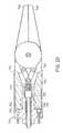
- FIG. 1is a perspective view illustrating a telerobotic system with which the concepts of the present invention may be practiced
- FIG. 2is a schematic diagram illustrating the degrees-of-freedom associated with the slave station of FIG. 1 ;
- FIG. 3is a plan view of the instrument insert of the present invention including the stem section and tool;
- FIG. 4is a cross-sectional view as taken along line 4 - 4 of FIG. 3 and illustrating further details of the stem section;
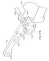
- FIG. 5is a perspective view of another embodiment of the tool of the present invention employing a flexible wrist section adjacent the tool;
- FIG. 6is an exploded perspective view of the embodiment of FIG. 5 ;
- FIG. 7is a cross-sectional view of the embodiment of FIG. 5 and as taken along line 7 - 7 of FIG. 6 ;
- FIG. 8is a longitudinal cross-sectional view of the embodiment illustrated in FIGS. 5-7 and showing further details at the wrist flexure;
- FIG. 9is a longitudinal cross-sectional view similar to that shown in FIG. 8 but for still another embodiment of the present invention using a single actuation element;
- FIG. 10is an enlarged fragmentary view of further details of the actuation element at the center of the wrist section
- FIG. 11is a cross-sectional view through the actuation element of FIG. 10 as taken along line 11 - 11 ;
- FIG. 12is a cross-sectional view through still another embodiment of the actuation element
- FIG. 13is still a further cross-sectional view of a further embodiment of the actuation element
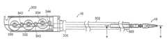
- FIG. 14is a perspective view of yet another embodiment of the present invention employing a slotted flexible wrist section and a detachable and preferably disposable tool;
- FIG. 15is a cross-sectional view through the embodiment of FIG. 14 as taken along line 15 - 15 of FIG. 14 ;
- FIG. 15Ais a fragmentary cross-sectional view of an alternate embodiment of the flexible section
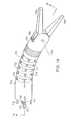
- FIG. 16is an exploded perspective view of the embodiment of FIG. 14 showing the detached tool in cross-section;
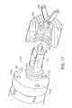
- FIG. 17is a further perspective view of the embodiment of FIG. 14 ;
- FIGS. 18-20illustrate sequential cross-sectional views showing the mating of the tool with the distal end of the instrument
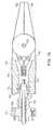
- FIG. 21is a schematic diagram illustrating principles of the present invention in a catheter or flexible instrument using multiple controllable bendable sections along the instrument;
- FIG. 22is a schematic diagram of an embodiment of an instrument with both elbow and wrist pivot joints, as well as a disposable tool
- FIG. 23is a schematic diagram of an embodiment of an instrument with just a wrist pivot joint, as well as a disposable tool
- FIG. 24is a diagram showing further details of a wrist joint useable with a disposable tool
- FIG. 25is a partially cut-away schematic view of another joint construction
- FIG. 26is a perspective view of a another embodiment of a tool
- FIG. 27is an exploded perspective view of the tool of FIG. 26 illustrating separate components thereof;
- FIG. 27Ais an exploded fragmentary view of one form of resilient member used in the embodiment of FIG. 27 ;
- FIG. 27Bis an exploded fragmentary view of another form of resilient member used in the embodiment of FIG. 27 ;
- FIG. 28is a side elevation view of the tool depicted in FIGS. 26 and 27 ;
- FIG. 29is an enlarged partial top plan view as seen along line 29 - 29 of FIG. 28 and illustrating further details of the tool;
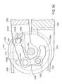
- FIG. 30is a cross-sectional view as taken along line 30 - 30 of FIG. 29 showing the tool of the present invention with the jaws in a partially open position;
- FIG. 31is a cross-sectional view like that illustrated in FIG. 30 but with the jaws in a fully closed position;
- FIG. 32is a somewhat schematic cross-sectional view of the first embodiment of the tool with the resilient pad partially compressed in grasping a small diameter item such as a thread or suture;
- FIG. 33is a somewhat schematic cross-sectional view of the first embodiment of the tool with the resilient pad essentially fully compressed in grasping a larger diameter item such as a needle;
- FIG. 34is a perspective view of a second embodiment of the invention employing a flexure gap in one of the jaws;
- FIG. 35is an exploded perspective view of the tool of this second embodiment of the invention.
- FIG. 36is a plan view of the tool of FIGS. 34 and 35 ;
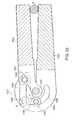
- FIG. 37is a cross-sectional view taken along line 37 - 37 of FIG. 36 with the jaws having a slight gap at their closed position;
- FIG. 38is a cross-sectional view like that illustrated in FIG. 37 but with the jaws grasping a needle or the like, and with the flexure gap in a substantially closed position;
- FIG. 39is a cross-sectional view similar to that depicted in FIGS. 37 and 38 , and of yet another embodiment of the invention illustrating the tool in a partially open position;
- FIG. 40is a cross-sectional view the same as that depicted in the embodiment of FIG. 39 but with the jaws in a more closed position;
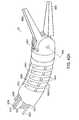
- FIG. 41is a perspective view of an embodiment of a flexible or bendable shaft segment just proximal to the tool
- FIG. 42is a cross-sectional view of the embodiment of FIG. 41 as taken along line 17 - 17 of FIG. 16 , and with the jaws in a substantially open position;
- FIG. 43is an enlarged partial cross-sectional view similar to that shown in FIG. 42 but with the jaws in a closed position;
- FIG. 44is an exploded perspective view showing the components including the flexible or bendable segment of FIG. 41 ;
- FIG. 45is a side elevation view of the flexible or bendable section itself
- FIG. 46is a cross-sectional view through the flexible or bendable section as taken along line 46 - 46 of FIG. 45 ;
- FIG. 47is a cross-sectional view through the flexible or bendable section as taken along line 47 - 47 of FIG. 45 ;
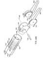
- FIG. 48Ais a perspective view of an alternate embodiment of the tool and flexible section
- FIG. 48Bis an exploded perspective view of the tool and flexible section illustrated in FIG. 48A ;
- FIG. 48Cis a fragmentary perspective view showing a portion of the flexible section shown in FIG. 48B ;
- FIG. 48Dis a plan view of the flexible section illustrated in FIGS. 48A-48C .
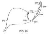
- FIG. 49illustrates a flexible instrument being used in a stomach of a subject in accordance with the invention.
- FIG. 50Ais a schematic of a flexible instrument with a pull-type cable to operate the end of the instrument in accordance with the invention.
- FIG. 50Bis cross-sectional view of a bendable section of the flexible instrument of FIG. 50A in accordance with the invention.
- FIG. 1illustrates a surgical instrument system 10 that includes a master station M at which a surgeon 2 manipulates an input device, and a slave station S including a surgical instrument illustrated generally at 14 .
- the input deviceis illustrated at 3 being manipulated by the hand or hands of the surgeon.
- the surgeonis illustrated as seated in a comfortable chair 4 , and the forearms of the surgeon are typically resting upon armrests 5 .
- FIG. 1illustrates a master assembler 7 associated with the master station a and a slave assembly 8 , also referred to as a drive unit, associated with the slave station S.
- Assemblies 7 and 8are interconnected by cabling 6 with a controller 9 , which typically has associated with it one or more displays and a keyboard.
- the drive unit 8is located remotely from the operative site and is preferably positioned a distance away from the sterile field.
- the drive unit 8is controlled by a computer system that is part of the controller 9 .
- the master station Mmay also be referred to as a user interface vis-vis the controller 9 .
- the computertranslates the commands issued at the user interface into an electronically driven motion in the drive unit 8 , and the surgical instrument, which is tethered to the drive unit through the cabling connections, produces the desired replicated motion. That is, the controller 9 couples the master station M and the slave station S and is operated in accordance with a computer algorithm, to be described in further detail below.
- the controller 9receives a command from the input device 3 and controls the movement of the surgical instrument 14 so as to replicate the input manipulation.
- FIG. 1also shows a patient P, upon whom the surgical procedure is performed, lying on an operating table T.
- the surgical instrument 14includes two separate instruments one on either side of an endoscope 13 .
- the endoscope 13includes a camera to remotely view the operation site.
- the cameramay be mounted on the distal end of the instrument insert, or may be positioned away from the site to provide an additional perspective on the surgical operation.
- FIG. 1three separate incisions are shown in the patient P, two side incisions for accommodating the surgical instruments and a central incision that accommodates the viewing endoscope. A drape covering the patient is also shown with a single opening.
- the surgical instrument 14also includes a surgical adaptor or guide 15 and an instrument insert or member 16 .
- the surgical adaptor 15is basically a passive mechanical device, driven by the attached cable array. Although the surgical adaptor can be easily seen in FIG. 1 , the instrument member 16 ( FIG. 3 ) is not clearly illustrated as it extends through the adaptor 15 .
- the instrument insert 16carries at its distal end a tool 18 , described in greater detail below.
- surgical instrumentAlthough reference is made herein to a “surgical instrument,” it is contemplated that the principles of this invention also apply to other medical instruments, not necessarily for surgery, and including, but not limited to, such other implements as catheters, as well as diagnostic and therapeutic instruments and implements.
- FIG. 1there is illustrated cabling 12 coupling the instrument 14 to the drive unit 8 .
- the cabling 12is preferably detachable from the drive unit 8 .
- the surgical adaptor 15may be of relatively simple construction. It may thus be designed for particular surgical applications such as abdominal, cardiac, spinal, arthroscopic, sinus, neural, etc.
- the instrument insert 16couples to the adaptor 15 , and essentially provides a means for exchanging the instrument tools.
- the toolsmay include, for example, forceps, scissors, needle drivers, electrocautery, etc.
- a surgeoncan manipulate the input device 3 at a surgeon's interface 11 , to effect a desired motion of the tool 18 within the patient.
- the movement of the handle or hand assembly at input device 3is interpreted by the controller 9 to control the movement of the tool 18 .
- the surgical instrument 14is preferably mounted on a rigid post 19 that is affixed to but removable from the surgical table T. This mounting arrangement permits the instrument to remain fixed relative to the patient even if the table is repositioned. In accordance with the present invention the concepts can be practiced even with a single surgical instrument, although, in FIG. 1 there are illustrated two such instruments.
- the surgical instruments 14are connected to the respective drive units 8 with cablings that include two mechanical cable-in-conduit bundles 21 and 22 .
- These cable bundles 21 and 22may terminate at two connection modules, which removably attach to the drive unit 8 .
- connection modules 23 and 24can be found in the earlier co-pending application No. PCT/US00/12553, the entire contents of which are incorporated herein by reference. Although two cable bundles are described here, it is to be understood that more or fewer cable bundles can be used.
- the drive unit 8is preferably located outside the sterile field, it may be draped with a sterile barrier so that it can be operated within the sterile field.
- the tool 18 of the surgical instrument 14is inserted into the patient through an incision or opening, and the instrument 14 is then mounted to the rigid post 19 using a mounting bracket 25 .
- the cable bundles 21 and 22are then extended away from the operative area to the drive unit 8 , and the connection modules of the cable bundles are engaged into the drive unit 8 .
- Instrument inserts 16may then be passed through the surgical adaptor 15 , and coupled laterally with the surgical adaptor 15 through an adaptor coupler, as described below in further detail.
- the instrument 14is controlled by the input device 3 , which is manipulated by the surgeon. Movement of the hand assembly produces proportional movement of the instrument 14 through the coordinating action of the controller 9 . It is typical for the movement of a single hand control to control movement of a single instrument.
- FIG. 1shows a second input device that is used to control an additional instrument. Accordingly, in FIG. 1 two input devices associated with the two instruments are illustrated.
- the surgeon's interface 11is in electrical communication with the controller 9 primarily by way of the cabling 6 through the master assembly 7 .
- Cabling 6also couples the controller 9 to the actuation or drive unit 8 .
- the actuation or drive unit 8is in mechanical communication with the instrument 14 .
- the mechanical communication with the instrumentallows the electromechanical components to be removed from the operative region, and preferably from the sterile field.
- the surgical instrument 14provides a number of independent motions, or degrees-of-freedom, to the tool 18 . These degrees-of-freedom are provided by both the surgical adaptor 15 and the instrument insert 16 .
- FIG. 2Shown in FIG. 2 is a schematic representation of the joint movement associated with the slave station S.
- the first joint movement J 1represents a pivoting notion of the instrument about the pivot pin 225 at axis 225 A.
- the movement relating to joint J 2which is a transitional movement of the carriage 226 on the rails 224 to move the carriage as well as the instrument 14 , supported therefrom, in the direction indicated by the arrow 227 in FIG. 2 towards and away from the operative site OS.
- the cabling in the bundle 21controls both the J 1 and J 21 movements.
- the distal end of the guide tube 17extends to the operation site OS.
- the operation sitemay be defined as the general area in close proximity to where movement of the tool occurs, usually in the viewing area of the endoscope and away from the incision.
- FIG. 2also depicts the rotary motion of both the adaptor tube 17 and the instrument stem. These are illustrated in FIG. 2 as respective motions or joints J 3 (adaptor tube rotation) and J 4 (instrument stem rotation). Motion J 5 indicates a wrist pivot or, alternatively, a wrist flexure. Finally, motions J 6 and J 7 represent the end jaw motions of the tool 18 .
- joints J 4 -J 7allows the instrument insert 16 to be actuated with four degrees-of-freedom.
- the insert 16 and adaptor 15provide the surgical instrument 14 with seven degrees-of-freedom.
- four degrees-of-freedomare described here for the instrument insert 16 , it is to be understood that greater or fewer numbers of degrees-of-freedom are possible with different instrument inserts. For example an energized insert with only one gripper may be useful for electro-surgery applications, while an insert with an additional linear motion may provide stapling capability.
- FIG. 2shows the incision point along the dashed line 485 , and a cannula 487 that in some surgical procedures is used in combination with a trocar to pierce the skin at the incision.
- the guide tube 17is inserted through the flexible cannula 487 so that the tool is at the operative site OS.
- the cannulatypically has a port at which a gas such as carbon dioxide enters for insufflating the patient.
- the cannulaalso is usually provided with a switch or button that can be actuated to desufflate.
- the cannulais used primarily for guiding the instrument, but may include a valve mechanism for preventing escape of gas from the body.
- FIG. 3is a plan view showing an instrument insert including the tool 18 , and elongated sections including a rigid section 302 and a flexible section 303 , with the tool 18 mounted at the end of the flexible stem section 303 .
- the coupler 300includes one or more wheels that laterally engage wheels of the coupler associated with the surgical adaptor.
- the coupler 300also includes an axial wheel 306 that also engages a wheel on the adaptor.
- the axial engagement wheel 306is fixed to the rigid stem 302 , and is used to rotate the tool axially at the distal end of the flexible stem section 303 .
- FIG. 3illustrates the base coupler 300 of the instrument insert 16 with wheels 330 , 332 , and 334 that have half-moon construction for engagement with mating like wheels of the adaptor. These wheels are meant to mate with the corresponding wheels of the adaptor. Also illustrated in FIG. 3 are capstans or idler pulleys 340 , 342 , and 344 associated with wheels 330 , 332 , and 334 , respectively.
- Each wheel of the couplerhas two cables that are affixed to the wheel and wrapped about opposite sides at its base.
- the lower cablerides over one of the idler pulleys or capstans, which routes the cables toward the center of the instrument stem 302 .
- the cablesare kept near the center of the instrument stem, since the closer the cables are to the central axis of the stem, the less disturbance the cables experience as the stem section moves (rotates).
- the cablesmay then be routed individually through plastic tubes that may be affixed, respectively, to the proximal end of the rigid stem 302 and the distal end of the flexible stem section 303 .
- the coupler 300there are six cables that connect to each of the wheels. Two cables connect to each wheel and one of these cables extends about the associated idler pulley or capstan. These are illustrated in FIG. 3 as idler pulleys 340 , 342 and 344 . Thus, six separate cables extend through the rigid stem 302 and down through the flexible stem section 303 to the area of the tool.
- Associated with the wheels 330 , 332 , and 334are six cables that extend through the sections 302 and 303 , as illustrated in FIG. 4 .
- One set of these cablescontrols the pivoting, such as the pivoting movement about pin 620 .
- the other cablescontrol the operation at the gripping jaws. For example, one pair of cables may control the movement of the lower jaw 652 , while another cable pair may control the operation of the upper jaw 650 .
- FIG. 4there is shown the rigid section 302 and the flexible section 303 of the instrument insert 16 .
- a series of six cables, illustrated at arrow 280 in FIG. 4extend through these sections and may be considered as separated into three sets for controlling the tool 18 , to provide the motions indicated in FIG. 2 as J 5 -J 7 .
- the cablingis supported near to the center axis of the rigid and flexible sections. Note that “de-coupling” simply means that any one controlled action associated with the tool, when performed, does not interfere with other controlled actions that may not be selected at the time that the one controlled action is taking place.
- the cablesOn the rigid section side of the block 282 the cables may be unsupported as shown or they could be held within a plastic sleeve either individually and/or as a group. Because the cables are maintained in tension and the rigid section is not meant to bend or flex, the cables can be held in position by being supported, as a group, at the center of block 282 .
- each individual cableis preferably held within a cable sleeve, such as illustrated in FIGS. 6 and 8 , to be described later in further detail.
- the cables contained in the sleeves 292are twisted, for example, 180 degrees over say 8 inches.
- spacers 286may be spaced along the flexible section 303 to hold the bundle 284 at the center of the section 303 .
- the individual cable sleevesalso define a substantially fixed length pathway for each cable so that even though the instrument may move or rotate, the cable lengths should stay the same within the flexible stem section.
- the sleevesmay be held in fixed position at their ends such as at block 282 at one end and at the tool 18 at the other end.
- the outer flexible tube 288may be a pliable plastic preferably having a fluted or bellows-like configuration, as illustrated.
- the limited twisting of the cable bundleprevents the formation of kinks or loops in individual cables that might occur if the cables were straight and parallel through the flexible section.
- This twistingalso provides the de-coupling between motions, so that actuation of one of the degrees-of-freedom (J 5 -J 7 ) does not cause a responding action at another degree-of-freedom (J 5 -J 7 ).
- the twistingessentially occurs between the block 282 and the location where the bundle enters the wrist joint (for example, the entry to base 600 ).
- the 180 degree twisting of the bundleensures that the cable sheathes are neither stretched nor compressed, even as the bendable section is bent or rotated.
- the construction of one form of toolis illustrated in FIGS. 3 and 4 .
- the tool 18includes the base 600 , link 601 , upper grip or jaw 650 and lower grip or jaw 652 .
- the base 600is affixed to the flexible stem section 303 .
- this flexible sectionmay be constructed of a ribbed plastic. This flexible section allows the instrument to readily bend through the curved actuator tube 17 .
- the link 601is rotatably connected to the base 600 about an axis 620 A represented by pivot pin 620 .
- the upper and lower jaws 650 and 652are rotatably connected to the link about axis 605 , where axis 605 is essentially perpendicular to the wrist axis at pin 620 .
- Another pivot pindefines axis 605 .
- the cablingmay travel through the instrument insert stem (section 303 ) and through a hole in the base 600 , wrapping around a curved surface on link 601 , and then attaches on link 601 .
- Tension on one set of cablesrotates the link 601 , and tension on other cables operates the upper and lower grips 650 and 652 , about axis pin 605 .
- the cablingis provided in pairs to provide an opposing action operation, including opposite routing paths, on the opposite sides of the instrument insert.
- the set of cables that control the jawstravels through the stem 302 , 303 and though holes in the base 600 . These cables then pass between two fixed posts 621 that constrain the cables so that they pass substantially through an axis 620 A, which defines the rotational motion of the link 601 .
- This constructionallows free rotation of the link 601 with essentially no length changes in the cables that actuate the jaws. In other words, these cables, which actuate the grips 650 and 652 , are effectively decoupled from the motion of link 601 .
- These cablespass over rounded sections and terminate on grips (or jaws) 650 and 652 , respectively. Tension on one pair of cables rotate grips 650 and 652 counter-clockwise about axis 605 .
- Another set of cablesprovides the clockwise motion to grips or jaws 650 and 652 , respectively.
- the ends of the cablescan be secured at the jaws 650 and 652 with the use of an adhesive such as epoxy glue, or the cables could be crimped or pinned to the jaw.
- the instrument 16slides through the guide tube 17 of adaptor 15 , and laterally engages the adaptor coupler 230 pivotally mounted to the base piece 234 .
- the base piece 234is rotationally mounted to the guide tube 17 , and is affixed to the linear slider or carriage 226 .
- the carriage 226is pivotally mounted at the pivot 225 about the axis 225 A.
- the tool 18includes an upper grip or jaw 650 and a lower grip or jaw 652 , supported from a link 601 .
- Each of the jaws 650 , 652 as well as the link 601may be constructed of metal, or alternatively, the link 601 may be constructed of a hard plastic.
- the link 601is engaged with the end of the flexible stem section 303 .
- FIG. 4shows the ribbed or fluted plastic construction of the flexible stem section 303 .
- the section 303may be smooth, at least at its distal end, as shown at 304 in FIG. 5 .
- both sections 302 and 303can be rigid depending upon the particular application.
- FIG. 5shows only the end of the stem section 303 (at 304 ), terminating in bending or flexing section 660 .
- Section 660may be integrally formed with the rest of section 303 .
- This section 660is controllably bendable or flexible usually from a remote location such as in accordance with the telerobotic system 10 of FIG. 1 .
- the stem section 303is preferably constructed so as to be flexible and may have either fluted or smooth outer surfaces.
- flexibility and bendingis enhanced by a bellows configuration 662 having saw-tooth shape of peaks and valleys as shown in FIG. 8 .
- the distal end of the bending section 660terminates with an opening 666 for receiving the end 668 of the link 601 .
- the bellows configurationmay be made of a single piece of material. Alternatively, the bellows configuration 662 may be made of segments connected together, for example, by welds. In any case, the bellows configuration 662 is a unibody construction.
- the bending or flexing section 660is constructed to have orthogonal bending movements to provide both pitch and yaw movement of the tool. This is accomplished by using four cables separated at 90.degree. intervals. These four cables include the cables 606 , 607 , 616 , and 617 . The operation of cables 606 and 607 provides flexing in one degree-of-freedom while an added degree-of-freedom (orthogonal to the just mentioned one degree-of-freedom) is provided by operation of cables 616 and 617 . As illustrated in FIG. 8 , these cables extend through the bellows about half way between each peak and valley and thus run in parallel but close to the outer periphery of the flexible section 660 .
- Each of the cables 606 , 607 , 616 , and 617terminate in a respective ball end 606 A, 607 A, 616 A, and 617 A, tensioned against an end wall 615 .
- These same cablesalso are supported by and extend through retainer block 621 . Within section 304 these cables also run near the outer wall as shown to the left in FIG. 8 where cables 616 and 617 are illustrated.
- the cables 608 , 609 , 610 , and 611extend through the flexible stem section 303 and also through the retainer block 621 , flexing section 660 , and the wall 615 . These cables extend to the respective jaws ( 650 , 652 ) to control the operation thereof in a manner similar to that described previously in connection with FIGS. 2-4 .
- the tool actuation cablesextend through the center of the bellows and are supported and retained between block 621 and wall 615 by the center sheath 290 .
- the center sheath 290may be constructed of a soft plastic material, and has an inner diameter sufficient to receive the bundle of cables, and an outer diameter that fits with little clearance against the inner diameter of the bellows 662 .
- the sheath 290extends between the block 621 and the wall 615 and is dimensioned to hold the cables, as a bundle, at the center axis of the bellows section. Keeping the bundle near the center axis provides proper de-coupling between the various degrees-of-freedom.
- each of the cablesis contained in its own cable sleeve 292 .
- These sleevesare sufficiently stiff to maintain constant cable lengths within the flexible or bendable section.
- these sleevesare shown extending between retainer block 621 and wall 615 .
- the cablesare shown extending from the sleeve when the cables reach the end tool.
- FIG. 8also illustrates the aforementioned twisting of the cables that assists in providing the de-coupling action between the tool operation and the controlled flexing or bending.
- the cablesare twisted about 180 degrees between the block 621 and wall 615 .
- the bellows sectionitself, may have a length of about one to three inches. Also, more than one bellows section may be used to provide controlled bending at more than one location. In that case separate control cabling is used for each section (see, e.g., FIG. 21 described later).
- the limited twisting of the cable bundleprevents the formation of kinks or loops in individual cables that might occur if the cables were left straight and parallel to one another.
- This twistingalso de-couples certain degrees of motions, so that actuation of one of the degrees-of-freedom does not cause a responding action at another degree-of-freedom.
- the twistingoccurs between the block 621 and the location where the bundle enters the wrist joint, i.e., the entry to base 601 .
- the individual cable sleevesalso define a substantially fixed length pathway for each cable so that even though the instrument may move or rotate the cable lengths stay the same within the section 660 .
- the cross-sectional view of FIG. 8gives details of the cabling in bending section 660 .
- the sheath 290extends essentially between block 621 and wall 615 and houses the twisted cables/sleeves.
- the individual sleeves 292can be considered as terminating at respective ends in blocks 621 and 631 .
- Each of the sleevesmay be glued or secured in any other appropriate manner in its supporting end block. This prevents the sleeves from moving axially as the cables are activated.
- the sleevesare preferably constructed of a plastic that is flexible and yet has sufficient rigidity so they do not kink when the cables are activated.
- the sleevesalso define fixed length pathways that do not compress or elongate as the cables are operated.
- the 180 degrees twist in the cables/sleevesoccurs essentially between blocks 621 and 631 .
- This “twisting” of the center cables/sleevesallows the section 660 to be controllably bent, while preventing or minimizing any transfer of motion to the tool operating cables.
- this arrangementalso prevents cross-coupling from the tool operation to the bending control, so that the tool operation alone does not cause any undesired bending of the section 660 .
- FIGS. 9-13there is shown another embodiment that includes bellows which can be bent of flexed in a controllable manner, for example, through a user interface like that shown in FIG. 1 .
- Similar reference charactersare used in FIG. 9 as those used in describing the embodiment of FIG. 5 .
- the embodiment of FIG. 9provides a single cable (or rod) actuation that simplifies the instrument construction, particularly at the tool end of the instrument. The single actuation is possible because the flexible section has two degrees-of-freedom to provide both pitch and yaw.
- the tool 18includes an upper grip or jaw 650 and a lower grip or jaw 652 , supported from a housing 670 .
- Each of the jaws 650 , 652 , as well as the housing 670may be constructed of metal, or alternatively, the housing 670 may be constructed of a hard plastic.
- the housing 670is engaged to the flexible stem section 303 with the bellows 662 .
- the flexible stem section 303can be a ribbed or fluted plastic construction like that shown in FIG. 4 , or alternatively, the section 303 may be smooth as shown at 304 in FIG. 9 .
- the jawsare operated from a single push/pull cable 672 that extends through the instrument stem and through the bellows 662 of the flexible or bendable section 660 .
- the cableis centered in the various sections as depicted in FIG. 9 so that when the bendable section is activated, no movement is transferred to the tool actuation cable.
- the bellows section 662expands on one side and compresses on the other side, leaving the center portion unchanged in length, and thus not effecting the cable action.
- the jawsthemselves are supported by a link bar arrangement shown at 675 that is appropriately secured at the distal end of the cable 672 . In the position shown in FIG. 9 the jaws are open, but by pulling on the cable away from the jaws the proximal end the link bar 675 pivots and closes the jaws 650 , 652 .
- the bending or flexing section 660can be bent to provide both pitch and yaw degrees of motion to the tool. This is accomplished by using four cables 606 , 607 , 616 , and 617 that are separated at 90.degree. intervals. The operation of cables 606 and 607 provides flexing in one degree-of-freedom while another degree-of-freedom is provided by the operation of cables 616 and 617 . As illustrated in FIG. 9 , these cables extend through the bellows about half way between each peak and valley of the respective bellows, and thus are parallel and near the outer periphery of the flexible section 660 .
- Each of the cables 606 , 607 , 616 , and 617terminates in a respective ball end 606 A, 607 A, 616 A, and 617 A, tensioned against the end wall 615 .
- These cablesalso are supported by and extend through retainer block 621 . Within section 304 these cables also run near the inner surface of the outer wall of the section 304 , as shown to the left in FIG. 9 where cables 616 and 617 are illustrated.
- the single actuation cable 672provides all the action that is required to operate the tool, which simplifies the construction of the instrument and makes it easier to keep the single cable centered in the instrument.
- a supporting sleeve 680that receives the cable 672 with a snug fit.
- the sleeve 680( FIG. 10 ) is preferably constructed of a polyethylene plastic such as PEEK which has the flexibility to flex with bending at the section 660 , but at the same time is sufficiently rigid to properly retain and hold the supported cable 672 to enable the cable to readily slide within the supporting sleeve 680 when performing its function.
- Sleeve 680defines a fixed length for the cable and does not allow any expansion or compression of the cable or sleeve.
- the sleeve 680may extend from the wall 615 back through the retainer block 621 and into the flexible section of the instrument, as shown in FIG. 9 .
- the sleeve 680may extend only through the section 660 and terminate at block 621 .
- a helical spring 682having an outer diameter to allow it to fit snugly within the inner diameter of the bellows 662 .
- a helical spring 682having an outer diameter to allow it to fit snugly within the inner diameter of the bellows 662 .
- Opposite ends of the helical spring 682are located between the block 621 and wall 615 .
- FIG. 10shows the spring shape and the relationship of the helical spring to the sleeve 680 and the actuation cable 672 .
- the coils of the springare shown spaced apart, but they can be more closely spaced then shown or completely closed.
- the spring 682may be free-floating about the sleeve 680 , and is preferably not engaged in any passage in the end supports, such as the passage in block 621 .
- the sleeve 680receives the cable 672 and is fixed in position relative to block 621 and wall 615 . Passages are provided in block 621 and wall 615 , and a glue or other securing arrangement is preferably used to hold the sleeve fixed at the block 621 and wall 615 .
- the spring 682is also used as a filler or spacer between the sleeve 680 and the bellows 662 inner surface.
- the springprovides a fixed position spacer since it is typically a metal, and thus will maintain the centering of the sleeve/cable, and yet is also flexible enough to bend when the section 660 is bent in a controlled manner.
- the sleeve itselfis preferably made of plastic such as PEEK which has sufficient strength to receive and guide the cable, yet is flexible enough so that it will not kink or distort, and thus keeps the cable in a proper state for activation, and defines a fixed length for the cable.
- the cable length at the center axis of section 660does not change when the section 660 is bent. That is, the bellows shortens on one side and expands on the other side while keeping the center axis length unchanged. In this way when bending occurs at section 660 there is no transfer of motion to the cable 672 which could undesirably move the jaws. Hence, the bending motion is de-coupled from the tool operation motion, and vice versa.
- FIG. 11is a cross-sectional view taken along line 11 - 11 of FIG. 10 showing the centered cable 672 , plastic sleeve 680 , and the helical spring 682 .
- FIG. 12is a similar cross-sectional view but for an alternate embodiment using only the center cable 672 and the sleeve 680 .
- the sleeve 680is larger in outer diameter in comparison to the sleeve shown in FIG. 11 so that there is a proper and close fit between the sleeve and the inside of the bellows.
- FIG. 13is a cross-sectional view through another embodiment of the cable support.
- This embodimentalso has the center cable 672 contained within the sleeve 680 , but in place of the spring 682 there is instead used a spacer 681 made of, for example, plastic, to keep the sleeve and cable centered in the bellows.
- the spacer 681may be constructed of a softer plastic than the sleeve 680 , or may be made of a plastic foam material.
- FIG. 9One of the benefits of the embodiment of FIG. 9 is that only a single cable is necessary to activate the tool. Recall that the pitch and yaw of the tool is controlled at the flexible wrist section 660 shown in FIG. 9 .
- This arrangementlends itself to making the tool disposable or at the very least detachable from the instrument body so that it can be replaced with a substitute tool.
- a detachable embodiment of the present inventionis illustrated in FIG. 14 and the companion views are shown in FIGS. 15-20 . Besides being detachable this arrangement also makes it possible to provide at least a resposable and preferably a disposable instrument tip or tool.
- FIG. 14a disposable tip is illustrated in conjunction with a flexible shaft or tube having a remotely controllable bending or flexing section 700 .
- the medical instrumentmay include an elongated shaft, such as shaft section 710 shown in FIGS. 14 and 15 , having proximal and distal ends, and a tool, such as graspers 702 and 704 , supported from the distal end of the elongated shaft and useable in performing a medical procedure on a subject.
- the distal end of the elongated shaft and the toolhave respective removably engaging portions that are readily engagable for positioning the tool at the distal end of the elongated shaft, and readily disengagable for removal of the tool from the distal end of the elongated shaft.
- the toolmay be detachable to facilitae substituting another tool, or the tool may be constructed to be readily disposable.
- the removably engaging portionsmay be snap-fitted together, or, as illustrated here, may be provided by a screw interlock between the distal end of the instrument shaft and the base or housing of the tool. Also, other forms of detachable engaging portions are considered as falling within the scope of the present invention.
- the detachable or disposable toolis used with a flexible controllably bendable section.
- the disposable toolcan be used with a wrist pivot or even a pair of successive wrist pivots that are orthogonal to one another for providing pitch and yaw movement at the tool.
- the disposable tool in this versionis also preferably actuated by a single actuation element, cable or the like.
- the toolis actuated by a single tendon or cable 736 that extends through the flexible section 700 .
- the bending or flexing section 700is constructed to have orthogonal bending movements by pulling on four cables 706 , 707 , 716 , and 717 separated at about 90.degree. intervals, and by using a center support 726 with ribs 712 extending from the center support 726 and defining slots 714 between adjacent ribs, as depicted in FIG. 15 .
- the ribs 712extend from a center support 726 that has extending therethrough a passage for receiving the cable 736 positioned within a sheath 730 .
- the ribs 712also provide a guide structure to the four cables 706 , 707 , 716 , and 717 .
- the bending section 700is a unibody construction that extends from the end of tube section 710 , which itself may be flexible, and it may be smooth as shown, or may be fluted as illustrated in FIG. 4 .
- This versionenables the bending section to be bent in orthogonal directions by the use of the four cables 706 , 707 , 716 , and 717 .
- the operation of cables 706 and 707provides flexing in one degree-of-freedom while another orthogonal degree-of-freedom is provided by the operation of cables 716 and 717 .
- Each of the cables 706 , 707 , 716 , and 717has at their terminating ends respective balls 706 A, 707 A, 716 A, and 717 A that may be held in corresponding recesses in a distal end wall 719 of the flexible section 700 .
- a bellows arrangementsuch as shown in FIG. 5 or 9 can be used.
- the structure shown in FIGS. 14-17preferably includes a plastic stiffener sheath or sleeve 730 that surrounds the cable 736 , and that fits closely within the passage of the center support wall 726 .
- the sleeve 730is preferably constructed of a polyethylene plastic such as PEEK which has enough flexibility to flex with the bending section section 700 , but at the same time is sufficiently rigid to properly retain, center and hold the supported cable to allow the cable 736 to readily slide within the supporting sleeve 730 in performing its function.
- the sleeve 730may extend from the distal end of the flex section 700 , back through the passage in the wall 726 , and into the shaft section 710 of the instrument, as shown in FIG. 15 .
- FIG. 15Athere is shown an alternate embodiment for the bending section 700 in which the sleeve 730 is eliminated.
- the passage in the wall 726is dimensioned to directly and snugly receive the cable 736 with a close tolerance fit but having sufficient clearance to allow the cable to readily slide in the instrument.
- the grippers 702 and 704are supported for opening and closing by the use of a pivot pin 735 that extends along axis 735 A in a housing 740 .
- a pivot pin 735that extends along axis 735 A in a housing 740 .
- the pin 735may be supported at its ends on opposite sides of housing 740 .
- the toolalso includes a pivot linkage 742 that intercouples the grippers with the actuation cable 736 such that as the linkage is moved in the axial direction by the cable 736 to open or close the jaws (or grippers).
- a pivot linkage 742that intercouples the grippers with the actuation cable 736 such that as the linkage is moved in the axial direction by the cable 736 to open or close the jaws (or grippers).
- FIG. 15the linkage and tool are shown in solid outline in the closed position, which corresponds to a “pulling” of the cable in a direction away from the tool.
- FIG. 15also shows, in dotted outline, the linkage and grippers in an open position, which corresponds to a “pushing” of the cable in a direction toward the tool.
- the grippersthemselves are prevented from any axial movement by the support at pin 735 , so when the linkage is operated from the cable 736 the resulting action is either opening or closing of the grippers, depending upon the direction of longitudinal translation of the actuating cable 736 .
- removably engaging portionswhich in the illustrated embodiment are formed by mating threaded portions. Further, these mating portions are provided both with respect to the actuation element (cable) as well as the stationary components of the tool and tube.
- the tool housinghas a threaded portion 746 with female threads
- the distal end of the flexible section 700as shown in FIG. 16
- the end of the actuation cable 736is terminated at block 750 , passing through a center passage in the threaded portion 748 .
- the block 750interacting with arms 751 , allows longitudinal sliding of the cable 736 , but prevents rotation thereof so that the tool can be screwed onto the shaft without rotating the actuation cable.
- the block 750supports a male threaded shaft 753 that is adapted to mate with the tool.
- the threaded portion at 753may have twice the threads per length as the threaded portion 748 .
- the block 750interacts with the arms as the tool is fully engaged to compensate for differences in thread pitch between the engaging members.
- FIG. 17shows the end of this linkage supporting a female threaded piece 760 .
- the female piece 760is threaded onto the male threaded shaft 753 in the direction indicated by the rotational direction arrow 770 .
- FIGS. 18-20there is shown the sequence of steps to attach the instrument tip to the shaft of the instrument. These views are somewhat schematic and are for the purpose of merely illustrating the steps taken in attaching the tool to the instrument shaft.
- FIG. 18the tool is first illustrated with its housing 740 about to engage at threaded female piece 760 with the corresponding threaded male shaft 753 .
- the threads of pieces 760 and shaft 753are finer that the threaded portions 748 and 746 .
- the threaded piece 760 and shaft 753are designed such that only about four turns are necessary to fully seat these members together.
- the sections 746 and 748have courser threads so that it takes, say, only about two turns to engage the two sections together.
- FIG. 19illustrates the positions of the various components after two turns have occurred between threaded shaft 753 and threaded piece 760 , and the other outer mating threaded sections are to engage.
- the threaded portions 746 and 748engage and after two more turns of the tool, the tool is fully engaged with the shaft, as illustrated in FIG. 20 .
- the detentsare also engaged so that the tool is, in essence, locked to the instrument shaft and ready for use.
- the block 750is free to move inward away from the tool.
- FIG. 21there is shown an embodiment having a detachable and disposable tool, and particularly adapted for application to a flexible instrument including a catheter.
- a detachable and disposable tooland particularly adapted for application to a flexible instrument including a catheter.
- the toolis operated remotely in a telerobotic manner from a user device such as shown in FIG. 1 .
- the use of multiple controllably bendable segments as shown in FIG. 21is particularly advantageous in a flexible instrument to assist in guidance thereof such as, for example, in vessels or arteries.
- FIG. 21shows primarily the distal end of a flexible instrument with the more proximal portions of the instrument being supported and driven in a manner similar to that illustrated in FIGS. 1 and 2 .
- the flexible instrument 800has two bending sections 810 and 815 spaced along the instrument shaft that are remotely actuable. In other configurations, these sections 810 and 815 can be formed directly in series, and more than two controllable segments can be used.
- a tool 820is positioned at the distal end of the instrument, and is preferably constructed to be disposable and may be substantially the same as the tool illustrated in FIGS. 14-17 including the interengaging portions for detachability of both the tool body and the tool actuation element. As shown in FIG.
- a cable 825is used as the actuation element. Also illustrated in FIG. 21 are instrument transition segments 830 and 835 , which may be similarly constructed as the flexible section 303 shown in FIG. 4 . Alternatively, one or both of these sections 830 , 835 may be rigid.
- the actuation elements (cables) that are not used to operate a particular sectionrun preferably through the center of the respective section to provide the proper de-coupling between the various degrees of movement.
- the center cable bundle 840 through the section 810includes the cables to operate section 815 and the tool 820 .
- each section 810 , 815is controlled with both pitch and yaw movements, then four cables are used to actuate each section.
- the actuation of each sectionis similar to the actuation of the embodiments shown earlier in FIGS. 5 and 9 .
- the aforementioned “twisting” conceptis also preferably used in each of these sections 810 , 815 where multiple cables are running through them, particularly in section 810 where five cables extend along the center of the section (four for actuation of the section 815 and one for tool actuation) similar to that shown in FIG. 8 .
- FIG. 21shows two of these cables terminating at 812 and used to operate and move the section 810 with one degree of freedom. Two other cables (displaced about 90 degrees) also terminate at the same general area and are used to operate the bending section 810 with the other degree-of-freedom.
- section 835four cables at 836 branch outwardly and terminate at the end of section 815 at 837 to control the flexing of section 815 .
- section 815there is thus only the single tool actuation cable 825 contained in a sheath extending through the center of the section.
- FIG. 21shows only two of the cables 836 for controlling one of the degrees-of-freedom of movement of the section 815 , there are two other cables (displaced about 90 degrees) that also terminate at the same location for the other degree-of-freedom of control of section 815 .
- FIG. 8can be made for the operation of the bending movement of the sections with the use of the cables.
- FIG. 21may be used for any number of different surgical procedures. Flexible instruments of this general type are shown in co-pending applications that have been incorporated herein by reference in their entirety. Although FIG. 21 shows four cables that are used to actuate a respective bending section, more or fewer cables can be used in each section. For example, if only one degree-of-freedom is desired in section 810 then only two actuating cables are employed to control bending in only one plane. The instrument may also be controlled for rotation to provide another degree-of-freedom.
- FIGS. 22 and 23disclose in a schematic manner this same disposability feature as applies to an instrument, whether flexible or rigid, that employs a wrist pivot or wrist and elbow pivot.
- FIG. 22is a schematic diagram of the instrument illustrating both elbow and wrist pivot joints, as well as the disposable tool.
- FIG. 23shows just a wrist pivot joint with a disposable tool. More specific details of portions of the diagrams can be found in earlier embodiments described herein.
- FIGS. 22 and 23like reference characters are used to identify like parts.
- an instrument 900that includes both an elbow joint 905 and a wrist joint 910 . These joints allow for orthogonal motions of the various segments about respective axes 905 A and 910 A. Both of these joints are driven by cabling in a manner as described earlier, such as in the pivot arrangement shown in FIGS. 3 and 4 . This cabling preferably runs through the center of the instrument as previously described.
- the instrument 900also includes an end tool 920 driven from a cable or rod 925 . This tool construction and its actuation element may be the same as described in FIGS. 14-17 , and would include separate interengagable/disengagable portions as previously described.
- FIG. 23there is shown an instrument 930 that includes only a single wrist joint 910 , along with the tool 920 actuated by means of the actuation element 925 .
- tool 920is preferably readily detachable in the manner shown in FIGS. 14-17 and is thus readily disposable.
- the instrumentmay be controllably rotated as indicated by the arrow 927 in FIG. 23 .
- FIG. 24illustrates a wrist or other joint that may be used for the joints shown FIGS. 22 and 23 .
- FIG. 24shows a ball joint 950 with intercoupling sections 951 and 952 .
- An actuation cable 954is also illustrated extending through sections 951 and 952 as well as through the middle of the joint 950 .
- the joint 950may be of a conventional type using mating outer pieces at 956 that enable the sections 951 and 952 to have relative rotation therebetween.
- a sheath 958that encloses the cable 954 , and that is preferably fixed in position at the top and bottom of the joint.
- the sheathis flexible and yet sufficiently durable so as to define a fixed length for the cable to extend through, even as the joint is actuated to rotate or pivot.
- Appropriate cablingmay be provided for control of the joint 950 .
- This type of jointis particularly advantageous in that the center of the joint is open and does not interfere at all with the passing of the actuation cable 954 and sheath 958 through the joint 950 . Again, by maintaining the cable at the center of the joint, as illustrated, even as the joint is actuated there is no adverse effect on the actuation cable. In other words as the joint rotates it does not change the length of the cable 954 , and thus these separate actions are de-coupled from each other.
- FIG. 25a further description of a wrist or other joint is illustrated that may be used for the joints shown in FIGS. 22 and 23 .
- FIG. 25shows a ball joint 960 intercoupling sections 961 and 962 .
- An actuation cable 964is also illustrated extending through sections 961 and 962 as well as through the middle of the joint 960 .
- the joint 960may be a conventional joint using mating outer pieces at 966 that enable the sections 961 and 962 to have relative rotation therebetween.
- Appropriate cablingmay be provided for control of the joint 960 .
- a funnel like surface illustrated at 970that directs the cable to an output orifice 972 where the cable is coupled into the section 962 .
- This funnel surface 970holds the cable such that as the sections experience relative rotation while the length of the cable within the joint is maintained at a fairly fixed length.
- the tool 18is within the scope of the invention, such as that illustrated in FIGS. 26-33 .
- a set of jawsis illustrated in the figures, but it is understood that other types of tool constructions may also be used with the concepts of the present invention.
- the instrument shaftmay be a rigid shaft, a flexible shaft, or combinations thereof.
- the tool 18includes four basic members including the base 1020 , link 1021 , upper grip or jaw 1022 and lower grip or jaw 1023 .
- the base 1020is affixed to the instrument shaft 1010 .
- the instrument shaft 1010may be rigid or flexible depending upon the particular use. If the shaft 1010 is flexible it may be constructed, for example, of a ribbed plastic material. A flexible shaft or section thereof would, in particular, be used in conjunction with a curved guide tube so that the instrument readily bends through the curved adaptor guide tube.
- link 1021is rotatably connected to the base 1020 about wrist pivot axis 1025 with a wrist pivot pin at 1026 .
- the upper and lower jaws 1022 and 1023are rotatably connected to the link 1021 about axis 1028 with a pivot pin 1030 , where axis 1028 is essentially perpendicular to axis 1025 .
- the jawsmay also be referred to as grippers or graspers.
- Cable 1036 - 1041actuate the wrist, namely the link 1021 , as well as the end effector or tool 18 .
- Cable 1036extends through the instrument shaft and through a hole in the base 1020 , wraps around curved surface 1032 on link 1021 , and then attaches on link 1021 at 1034 .
- Tension on cable 1036rotates the link 1021 , as well as the upper and lower jaws 1022 and 1023 , about axis 1025 .
- Cable 1037provides the opposing action to cable 1036 , and goes through the same routing pathway, but on the opposite side of the instrument shaft. Cable 1037 is also attached to link 1021 generally at 1034 .
- Cables 1038 and 1040also travel through the instrument shaft 1030 and though holes in the base 1020 .
- the cables 1038 and 1040then pass between two fixed posts 1035 . These posts constrain the cables to pass substantially through the axis 1025 about which the link 1021 rotates.
- This constructionallows the link 1021 to rotate freely with minimal length changes in cables 1038 - 1041 .
- the cables 1038 - 1041which actuate the jaws 1022 and 1023 , are essentially decoupled from the motion of link 1021 .
- Cables 1038 and 1040pass over rounded sections and terminate on jaws 1022 and 1023 , respectively.
- the application of tension on cables 1038 and 1040rotate jaws 1022 and 1023 counter-clockwise about axis 1028 .
- cables 1039 and 1041pass through the same routing pathway as cables 1038 and 1040 , but on the opposite side of the instrument. These cables 1039 and 1041 provide the clockwise motion to grips or jaws 1022 and 1023 , respectively. The ends of cables 1038 - 1041 may be secured at 1033 of the jaws 1022 and 1023 .
- the tool 18includes a rotation piece 1045 , a linkage 1046 and slotted linkage 1048 .
- the rotation piece 1045has a centrally disposed hole 1045 A that is adapted to receive the pivot pin 1030 .
- the pivot pin 1030also passes through holes 1023 A in one jaw member and holes 1022 A in the other jaw member.
- the pin 1030is secured in respective holes in the arms 1029 of the link 1021 in a well-known manner to rotatably support the jaw members from the link 1021 .
- the rotation piece 1045also carries an actuation pin 1050 extending in the same direction as the pivot pin 1030 , and parallel thereto.
- the actuation pin 1050extends into curved J-shaped slots 1052 in respective jaw flanges 1054 of jaw 1023 .
- the actuation pin 1050is also received by the linkage 1048 through the end hole 1048 A, and the linkage is supported between the spaced flanges 1054 of the jaw 1023 .
- At the slotted end of the linkage 1048there is a set of holes 1048 B that receive the pin 1056 .
- the linkage 1048also pivotally attaches with the linkage 1046 by virtue of the pin 1056 passing through the holes 1046 B and 1048 B.
- the pin 1056is also positioned in the slots 1052 of the flanges 1054 , and thus moves along the slots to different positions, two of which are illustrated in FIGS. 30 and 31 . When the jaws are fully closed, the pin 1056 is at the very top of the slot 1052 as illustrated in FIG. 31 .
- FIG. 30shows the pin 1056 in a lower position which occurs when the jaws are partially opened.
- the pin 1050likewise is in different positions in the slot 52 depending upon the position of the jaws.
- the linkage 1046is also supported at its other end at hole 1046 A by the pin 1058 .
- the pin 1058also passes through a set of holes 1022 B in the base of the jaw 1022 .
- the linkage 1046fits in a slot at the base of the jaw 1022 , and the pin 1058 passes through both the base of the jaw 1022 as well as the linkage 1046 .
- the pin 1058also preferably has a compliant member such as a set of resilient members disposed about at least a portion thereof, as illustrated in FIGS. 30 and 31 , at 1060 , in an uncompressed position.
- FIG. 31shows the resilient cups 1060 uncompressed
- FIG. 32shows the resilient cups partially compressed when the jaws are grasping a small diameter member such as a suture S.
- FIG. 33shows the cups 1060 essentially fully compressed, when the jaws are grasping a larger diameter member such as a needle N.
- the cups 1060may fit about the pin 1058 , and be disposed in the base of the jaw 1022 .
- the holes 1022 B that receive the cups 1060are of somewhat elongated shape, such as illustrated in FIGS. 27A , 27 B, 30 , and 31 .
- the jaws 1022 and 1023apply a smaller but sufficient force to hold a smaller diameter item, such as the suture S than when holding a larger item such as a needle N.
- This forceis primarily a function of the resiliency of the cups 1060 .
- the toolis constructed so that when the jaws are holding an item the size of a needle N the cups 1060 are essentially fully compressed, and a maximum grasping force is applied to the needle N. This is particularly desirable for important surgery techniques for the securing and controlling of the needle.
- the pin 1056When the jaws 1022 and 1023 first make contact with an item positioned between them, the pin 1056 is in a contact position A′ ( FIG. 33 ) for a larger item such as the needle N, or further up the slot 1052 at a position A ( FIG. 32 ) for a smaller item such as the suture S. When a sufficient force is applied to the item with the jaws, the pin 1056 moves to a locked position B ( FIGS. 32 and 33 ), regardless of the size of the item being grasped.
- FIGS. 27A and 27BOther embodiments of the resilient members are shown in the fragmentary exploded views of FIGS. 27A and 27B .
- the embodiment of FIG. 27Auses a pair of cups 1060 A, while the embodiment of FIG. 27B uses only a single cup.
- the same reference charactersare used as in FIG. 27 to identify like components.
- the cups 1060 Aare positioned within respective holes 1022 B. They may be positioned with the use of an adhesive.
- the cups 1060 Aare thus be located at opposite ends of the pin 1058 . When the jaws are in the closed position, these cups 1060 A are compressed as the pin 1058 rides downwardly in the somewhat elongated hole or slot 1022 B.
- FIG. 27Auses a pair of cups 1060 A
- FIG. 27Buses only a single cup.
- the same reference charactersare used as in FIG. 27 to identify like components.
- the cups 1060 Aare positioned within respective holes 1022 B. They may be positioned with the use of an adhesive.
- the single cup 1060 Bis of somewhat larger shape than the cups 1060 A and is located between the spaced walls of the base 1022 C.
- the link 1046is positioned between these walls, as is the cup 1060 B.
- the cup 1060 Bmay also be secured in position by an adhesive.
- the cup 1060 Bis engaged by the end of the link 1046 .
- the pin 1058also rides within the elongated slots 1022 B and when the jaws are moved to a closed position the end of link 1046 bears against the cup 1060 B.
- the actuation cables for the end effectorinclude the cables 1038 - 1041 .
- One set of cablesactuates the rotation piece 1045
- the other set of cablesactuates the jaw 1023 .
- the other jaw 1022is actuated through the coupling provided from the rotation piece 1045 to the jaw 1022 , including pin 1050 and the associated linkages 1046 and 1048 controlled via pins riding in slots 1052 .
- These linkagesprovide direct drive from the rotation piece 1045 to the base of the jaw 1022 , to control the pivoting motion of that jaw, controlled usually from a remote location.
- FIGS. 34-38Another embodiment of the tool 18 is illustrated in FIGS. 34-38 , where FIG. 34 is a perspective view of the tool while FIG. 35 is an exploded perspective view showing the separate components of the tool.
- FIG. 34is a perspective view of the tool while FIG. 35 is an exploded perspective view showing the separate components of the tool.
- the same reference charactersare used to designate similar components.
- the tool 18 shown in FIGS. 34-38includes four basic members including a base 1020 , a link 1021 attached to the base, an upper grip or jaw 1022 , and a lower grip or jaw 1023 .
- the baseis affixed to an instrument shaft in a manner similar to that depicted in FIG. 26 .
- the instrument shaftmay be rigid or flexible depending upon the particular use.
- the link 1021may be rotatably connected to the base about a wrist axis such as the axis 1025 of the just previously described embodiment.
- the upper and lower jaws 1022 and 1023are rotatably connected to the link 1021 about axis 1028 with a pin 1030 that is substantially perpendicular to axis 1025 .
- Cable 1036 - 1041actuate the wrist, namely the link 1021 , as well as the end effector or tool 18 .
- Cable 1036extends through the instrument shaft and through a hole in the base, wraps around curved surface 1032 on link 1021 , and then attaches on link 1021 at 1034 ( FIG. 35 ).
- Tension on cable 1036rotates the link 1021 , and the upper and lower jaws 1022 and 1023 , about the wrist axis.
- Cable 1037provides the opposing action to cable 1036 , and goes through the same routing pathway, but on the opposite side of the instrument shaft. Cable 1037 is also attached to link 1021 generally at 1034 .
- Cables 1038 and 1040also travel through the instrument shaft and though holes in the base.
- the cables 1038 and 1040then pass between two fixed posts that are similar to the posts 1035 in FIG. 26 . These posts constrain the cables so that they pass substantially through the wrist axis about which the link 1021 rotates.
- This constructionallows the link 1021 to freely rotate with minimal length changes in cables 1038 - 1041 .
- the cables 1038 - 1041which actuate the jaws 1022 and 1023 , are decoupled from the motion of link 1021 .
- Cables 1038 and 1040pass over rounded sections and terminate on jaws 1022 and 1023 , respectively.
- the application of tension on cables 1038 and 1040rotate jaws 1022 and 1023 counter-clockwise about axis 1028 .
- cables 1039 and 1041pass through the same routing pathway as cables 1038 and 1040 , but on the opposite side of the instrument. These cables 1039 and 1041 provide the clockwise motion to jaws 1022 and 1023 , respectively. The ends of cables 1038 - 1041 are secured at 1033 of the jaws 1022 and 1023 .
- the tool 18includes the rotation piece 1045 , along with linkage pair 1066 and straight linkage 1068 .
- the rotation piece 1045has a central hole 1045 A that receives the pivot pin 1030 .
- the pivot pin 1030also passes through holes 1023 A in one jaw member and hole 1022 A in the other jaw member.
- the pin 1030is secured to respective holes in the arms 1029 of the link 1021 to rotatably support the jaw members from the link 1021 .
- the rotation piece 1045also carries an actuation pin 1050 extending in the same direction as the pivot pin 1030 , and parallel thereto.
- the actuation pin 1050extends into curved slots 1052 in respective jaw flanges 1054 of jaw 1023 , as shown in FIGS. 35 , 37 , and 38 .
- the actuation pin 1050is also received through an end hole 1068 A of the linkage 1068 , and the linkage is supported between the spaced flanges 1054 of the jaw 1023 .
- a hole 1068 Bthat receives the pin 1076 .
- the linkage 1068also pivotally attaches with the linkage pair 1066 by virtue of the pin 1076 passing through the holes 1066 B and 1068 B.
- the pin 1076is also positioned in the slots 1052 of the flanges 1054 , and thus moves along the slots to different positions, two of which are illustrated in FIGS. 37 and 38 . When the jaws are in a substantially closed position, the pin 1076 is at the top of the slot 1052 as illustrated in FIG. 37 . When the jaws are in other positions, the pin 1050 will reside in different positions in the slot 1052 .
- the linkages 1066are also supported at its other ends at holes 1066 A the pin 1078 .
- the pin 1078also passes through a hole 1022 B in the base of the jaw 1022 .
- the basehas a support wall 1022 D in which the hole 1022 B is located.
- the linkage pair 1066fits on opposite sides of the wall 1022 D, and the pin 1078 passes through both the base of the jaw 1022 as well as the linkage pair 1066 .
- the actuation cables for the end effector or toolinclude the cables 1038 - 1041 .
- One set of cablesactuates the rotation piece 1045
- the other set of cablesactuates the jaw 1023 .
- the other jaw 1022is actuated through the coupling provided from the rotation piece 1045 to the jaw 1022 , including pin 1050 and the associated linkages 1046 and 1048 riding in slots 1052 .
- These linkagesprovide direct drive from the rotation piece 1045 to the base of the jaw 1022 , to control the pivoting motion of that jaw, typically from a remote location.
- control of the grasping force on an itemis provided primarily by means of a slot or gap in one of the jaws.
- Thisis illustrated in FIGS. 34-38 by the gap 1031 located near the base 1022 C in the jaw 1022 .
- FIGS. 35 , 37 , and 38show in particular the shape and depth of the gap 1031 .
- the gap 1031is located above a hinge 1044 where the jaw can deflect when grasping and holding an item, regardless of its size, and with a firm grasping force.
- the gap 1031may be terminated in a tubular passage 1031 A to enhance the hinging effect of the hinge 1044 .
- the hinge 1044acts as a compliance member similar to the resilient members 1060 described with reference to FIGS. 27-33 .
- FIGS. 37 and 38the jaws 1022 , 1023 are shown in a substantially closed position in FIG. 37 grasping a suture S. In that position it is noted that both of the pins 1050 and 1076 are substantially at their top transition locations.
- FIG. 38illustrates the jaws 1022 , 1023 grasping an item such as a needle N that causes the jaw 1022 to flex and consequently the gap 31 to close up. This flexure enables the application of a varied grasping force at the tip of the jaws. When the links are at the end of their travel, the jaw 1022 flexes when the jaws 102 , 1023 grasp an item. The amount of flexure depends on the diameter of the item being grasped.
- the jaws 1022flexes to a lesser extent when a smaller diameter item such as a suture S is being grasped then when a larger item such as a needle N is being held. That is, to grasp a smaller item, the gap 1031 closes to a lesser extent, while the jaw. As still apply a sufficient holding force to the item. This force is primarily a function of the resiliency at the gap, as defined primarily by the flexure capability at the hinge 1044 . The larger the diameter of the item being held, the larger the corresponding holding force.
- the toolis constructed so that, for an item the size of a needle, as shown in FIG.
- the gap 1031is fully closed with the sides of the top of the gap touching, with a maximum grasping force being applied to the needle N. This is particularly desirable for the securing and controlling of the needle in important surgery techniques.
- the pin 1076is at a contact position A′ ( FIG. 38 ) when the jaws first make contact with a larger item such as the needle N, or further up the slot 1052 at a contact position A ( FIG. 37 ) when the jaws contact a smaller item such as the suture S. Regardless of the size of the item, the pin moves to a locked position B ( FIGS. 37 and 38 ) when the sufficient force is applied to lock the jaws onto the item.
- a “locked” position B of the pins or jawscorresponds to a position wherein the linkages are disposed at right angles to each other.
- the linkages 1046 and 1048are disposed at right angles (90 degrees) to each other. This provides virtually infinite grasping force with essentially no back drive at the jaws.
- the linkages 1066 and 1068that are disposed at right angles when locked.
- FIGS. 39 and 40This embodiment has a structure very similar to that described in detail in FIGS. 26-33 .
- the resilient cup 1060there is provided a modified jaw slot configuration.
- the slots 1052 in jaw 1023have a curved segment 1052 A, and a straight segment 1052 B.
- the J-slots 1052also have a contiguous end slot 1052 C that extends back toward the tip of the jaw tip.
- the overall slot configurationis C-shaped.
- the jawsare in a substantially open position with a gap G 1 as noted when the jaw members 1022 , 1023 are locked onto and the needle N, with the pin 1056 located at a locked position B.
- the pin 1056Before the jaws make contact with the needle N, the pin 1056 may be out of the end slot 1052 C, and the pins 1050 and 1056 are located at different positions along the slots 1052 depending upon the degree of openness of the jaws.
- the pin 1056When the jaws contact the needle N, the pin 1056 is at a contact position A′.
- the jawsIn FIG. 40 the jaws are in a substantially closed position with a small gap G 2 as the jaws grasp a smaller item such as a suture S.
- the pin 1056now moves further into the end slots 1052 C to the locked position B, as the jaws apply a grasping force to an item to lock the suture between the jaws.
- the pin 1056When contact is first made between the jaws and the suture, the pin 1056 is located at the contact position A further up the slot 1052 than the contact position A′ of FIG. 39 . Thus, depending upon the size thereof, the pin 1056 moves to a greater or lesser extent into the slots 1052 C.
- the pins 1050 and 1056are in the position illustrated in FIG. 39 with there being a maximum grasping force applied to the item by virtue of the links 1046 and 1048 being positioned at 90 degrees relative to each other.
- the pinsrotate slightly further clockwise with the pin 1056 moving into the slot 1052 C as illustrated in FIG. 40 .
- the jaw and linkagesmove together as a rigid body while closing against the suture.
- slots 1052 Clike the resilient member 1060 ( FIGS. 27-33 ) and the hinge 1044 ( FIGS. 37 and 38 ), are accommodating mechanisms that allow a closing force to be applied to grasped items of different sizes as the force is applied to the grasped item as the jaws close to a position at which the jaws remain open.
- the accommodating mechanisms described above like the slots 1052 C ( FIGS. 39 and 40 ), the resilient member 1060 ( FIGS. 27-33 ), and the hinge 1044 ( FIGS. 37 and 38 ,can be implemented in other types of grasping mechanisms as well, such as those described in U.S. application Ser. No. 09/827,643, filed Apr. 6, 2001, and U.S. application Ser. No. 10/014,143, filed Nov. 16, 2001, the entire contents of which are incorporated herein by reference.
- the medical instrumentincludes a jaw or work members controlled by a drive mechanism that is used to open and close the jaws or work members for applying an increased force to an item grasped between the jaws or work members.
- the accommodating mechanisms described abovesuch as the slots 1052 C ( FIGS. 39 and 40 ), the resilient member 1060 ( FIGS. 27-33 ), and the hinge 1044 ( FIGS. 37 and 38 , each have the characteristic of providing a maximum grasping force at what may be considered a maximum grasping position. This corresponds to the positions illustrated, and discussed previously, in FIGS. 33 , 38 , and 39 .
- the instrumentis constructed so that this maximum position corresponds to a predetermined size or diameter items that is to be grasped, usually a needle in this case.
- a predetermined size or diameter items that is to be graspedusually a needle in this case.
- the grasping forceis progressively less.
- the forceis less because the compliant member is compressed less.
- the linkagedoes not go to the top of the J-slot and thus the applied force is also less in that case, as the linkages are not yet to a maximum force 90 degree position.
- the accommodating mechanismallows the jaws or work members to be closed beyond this maximum grasping position in order to grasp items of various sizes, particularly smaller size items. Again, this is illustrated by way of example in FIG. 32 where the jaws go past their maximum grasping position, closing to a closer position therebetween, in grasping the suture S. In FIG. 37 this is illustrated by the jaws closing to grasp the suture S with less force being imposed by the flexure at the jaw 1022 . This is also illustrated in FIGS. 39 and 40 . In FIG. 39 the jaws are at their maximum grasping position. In FIG. 40 the jaws are closed beyond this maximum grasping position to grasp the smaller size suture S.
- the accommodating mechanismin this case may be considered as including the slot segment 1052 C that enables further rotation of the linkages to the position illustrated in FIG. 40 .
- FIGS. 41-47another embodiment of a flexible or bending segment with a unibody construction which can be used with any suitable end effector like the tools 18 described above, whether used with a rigid shaft body or a flexible shaft body or combinations thereof.
- one of the benefits of the embodiment shown in FIGS. 41-47is that only a single cable 1136 needs to be coupled to the tool 18 to actuate it.
- the pitch and yaw of the tool 18is controlled at the flexible section 1100 shown in FIG. 41 .
- This arrangementalso lends itself to making the tool disposable or at the very least detachable from the instrument body to facilitate substituting another tool.
- a toolcan be constructed that is readily detachable from the instrument.
- the bendable section 1100is depicted near the tool, the bendable section can be located at other locations further away from the tool. Since the tool 18 of the embodiment shown in FIGS. 41-47 requires only a single actuation cable, it is simpler to operate than the wrist/tool combination shown in FIGS. 26 and 27 . Recall, in the wrist arrangement, a pivot axis does not accommodate single cable actuation. Thus, with the wrist unit one has to use a far more complex cabling scheme, such as, by way of example, the cabling arrangement illustrated in U.S. Pat. Nos. 6,312,435 and 6,206,903. Furthermore, the single cable actuation provides a more simplified design that readily lends itself to a variety of tool constructions.
- the instrumentIn order for the various degrees of motions to be decoupled from each other, and for the proper overall functioning of the distal end of the instrument, the instrument has certain preferred characteristics, particularly at the flexible or bendable section of the instrument shaft. These characteristics are listed below but are not in any particular order of significance. Embodiments can employ at least one of these characteristics. Furthermore, although these characteristics are listed with reference to the embodiment described in FIGS. 41-44 , one or more of the characteristics can apply as well to any of the other embodiments described earlier.
- a first characteristicis that the actuation element for the tool be centered in the flexible or bendable section. In this way, during any bending operation the center of the flexible or bendable section tends to maintain the same length, even though opposed outer surfaces of the section may, respectively, expand and contract. This, in essence, means that the bending action is not erroneously transferred to the actuation element for the tool, hence, de-coupling the bending operation from the tool actuation, and vice versa.
- a second characteristicis that the flexible or bendable section of the instrument shaft be readily flexible without the application of undue force.
- This bendable sectionin a preferred embodiment, is to have orthogonal bending characteristics, hence providing two degrees of freedom (DOF) to the distal tool, for example, yaw and pitch.
- DOFdegrees of freedom
- a substantial portion of the flexible or bendable sectionis located as near to the center neutral axis 1111 of the section as physically possible. This is achieved by the spaced rib construction including the ribs 1112 shown in the drawings.
- the slots 1114 defined by these ribs 1112provide void areas, leaving more material near the center neutral axis, as depicted in FIG. 45 .
- a third characteristicrelates to the torsional nature of the flexible or bendable section.
- the bendable sectionis torsionally stiff, then upon controlled rotation of the instrument shaft, there is no an undesired twisting action imparted on the shaft particularly at the flexible or bendable section 1100 .
- a substantial portion of the material forming the flexible or bendable sectionis located at the periphery of the flexible or bendable section. This may be achieved by having portions of the section extend to an outer surface.
- thisis accomplished by providing radial ridges, such as the ridges 1120 shown in the drawings. Furthermore, these ridges are alternated between horizontal and vertical positions to, at the same time, to provide the orthogonal bending or flexing.
- a fourth characteristicis that the flexible or bendable section of the instrument shaft is constructed so that there is little or no end-to-end compression.
- the flexible or bendable sectionmaintains a relatively constant length regardless of the motion actuations that occur in the multiple degrees of freedom movement of the instrument.
- a stiff memberis provided to maintain the ends of the flexible or bendable section at a fixed spacing. This may be achieved by providing the stiff member as a centrally located stiff sleeve that receives and supports the sliding motion of the actuation element for operation of the distal tool.
- This stiff memberis preferably fixed at its opposite ends to the bendable section to maintain the fixed length of the section, thereby preventing end-to-end compression. At least part of this member may include the sleeve 1182 depicted in FIG. 43 .
- the medical instrumentmay include an elongated shaft, such as shaft section 1110 shown in FIGS. 41 and 42 , having proximal and distal ends; and the tool 18 with jaws 102 and 104 , supported from the distal end of the elongated shaft and useable in performing a medical procedure on a subject.
- the tool 18is actuated preferably by a single tendon or cable 1136 that extends through the flexible section 1100 .
- the bending or flexing section 1100is constructed to bend in orthogonal directions with the use of four cables separated at about 90.degree. intervals and by using a center support with ribs and slots about the entire periphery of the bending section 1100 , as depicted in FIGS. 42-44 .
- This orthogonal bendingmay also be referred to as bi-axial bending, meaning bending in separate axes.
- the ribs 1112define corresponding slots 1114 , and also define at each of their centers a center support passage 1118 that has the cable 1136 extending through it, as well as other cable support members described in further detail later.
- the bending section 1100extends from the end of tube section 1110 , which itself may be flexible, may be smooth as shown, or may be fluted, and may have other controllable bending sections disposed along its length.
- cables 1106 , 1107 , 1116 and 1117To bend the bending section 1100 in orthogonal directions, use is made of the four cables 1106 , 1107 , 1116 and 1117 .
- the operation of cables 1106 and 1107provides flexing in one degree-of-freedom while an added orthogonal degree-of-freedom is provided by operation of cables 1116 and 1117 .
- Each of the cables 1106 , 1107 , 1116 , and 1117have at their terminating ends respective balls 1106 A, 1107 A, 1116 A, and 1117 A that may be held in corresponding recesses in a distal end wall 1119 ( FIG. 45 ) of the flexible section 1100 .
- the bending section 1100includes a series of spaced ribs 1112 positioned, in parallel, with the plane of each rib extending orthogonal to the neutral axis 1111 of the section 1100 .
- an end ribconnects to the shaft section 1110 , while at the distal end there is provided the distal end wall 1119 that supports the ends of the cables.
- Each of the ribs 1112are held in spaced relationship by means of the alternating ridges 1120 . As depicted in FIG. 43 these ridges are identified as horizontal ridges 1120 A, alternating with vertical ridges 1120 B. This structure provides support at the center passage for the actuating cable 1136 , while also providing torsional strength to prevent undesired twisting at the shaft section 1100 .
- the jaws 1102 and 1104are supported for opening and closing by means of a pivot pin 1135 that extends along a pivot axis. These grippers may be supported in link 1140 , and the pin 1135 may be supported at its ends in opposite sides of link 1140 .
- the toolalso includes a pivot linkage 1142 that intercouples between the grippers and the actuation cable 1136 .
- the pivot linkage 1142includes linkages 1142 A and 1142 B. At one end, each of the linkages 1142 A and 1142 B connects to respective jaws 1104 and 1102 . At the other end, the linkages 1142 A and 1142 B are pivotally supported at end 1137 of cable 1136 . Opposed pins extend from end 1137 for engagement with the linkages 1142 A and 1142 B.
- the jaws 1102 and 1104are shown having recesses 1102 A and 1104 A for accommodating the respective linkages 1142 B and 1142 A.
- FIG. 42the jaws 1102 and 1104 are shown in their open position with the linkages 1142 A and 1142 B shown in a forward pivoted configuration.
- FIG. 43illustrates the jaws 1102 and 1104 in a closed position with the linkages 1142 A and 1142 B shown in an in-line configuration.
- FIG. 43shows the linkage and grippers in a closed position.
- the structure shown in FIGS. 41-47preferably also includes a plastic cable sheath 1180 , a plastic stiffener sheath or sleeve 1182 that surrounds the cable 1136 and the sheath 1180 , and that fits closely in the center passage 1118 , and an outer silicon spacer 1184 .
- the sleeve 1182is preferably constructed of a polyethylene plastic such as PEEK which has flexibility to allow the sleeve 1182 to bend with the section 1100 , but at the same time is sufficiently stiff (particularly end-to-end) to properly retain, center and hold the supported cable to enable the cable to readily slide within the sheath 1180 and the supporting sleeve 1182 , in performing its function.
- the sleeve 1182is illustrated extending from the distal end of the bendable section 1100 , back through the passage, to the more proximal end of the bendable section 1100 .
- FIGS. 42 and 43also show the use of an adhesive, at 1186 , such an epoxy adhesive for anchoring opposite ends of the sheath 1180 and the sleeve 1182 to opposite ends of the bendable section 1100 .
- an adhesivesuch as epoxy adhesive for anchoring opposite ends of the sheath 1180 and the sleeve 1182 to opposite ends of the bendable section 1100 .
- FIG. 45Other features of the bending section are shown in FIG. 45 in a side elevation view, while FIGS. 46 and 47 illustrate cross-sectional views, with one through one of the ridges 1120 A and the other through one of the ridges 1120 B.
- the respective ridges 1120 A and 1120 Bare arranged at about 90 degrees to each other.
- the section 1100is easily bendable while being torsionally stiff, and has other improved characteristics as well. Details of these characteristics are best described with reference to FIGS. 45-47 by considering a particular cross-section such as the cross-section in FIG. 45 taken along line 46 - 46 .
- FIG. 45it is clear that, at that location and with the orientation of the section 1100 as shown, there is a substantial void created by the slot 1114 , so that the majority of the section material is located at the center of the section. This is consistent with the desired bendability at that location, since, in general, a structure becomes more bendable as its diameter deceases.
- the void area mentionedis also illustrated in the cross-sectional view of FIG. 46 at 1115 .
- the section 1100is constructed so that there is preferably a relatively large center passage 1118 , leaving more material toward the outer periphery, which is desired for providing enhanced torsional stiffness. Note that this material is the material of the ridge itself. Thus, for torsional stiffness it is desired to have a void near the middle and more material located away from the middle.
- the rib and ridge arrangement shown in the drawingsthus provides in a single structure a bendable section that provides two degrees of freedom (biaxial motion) that is also torsionally stiff.
- the bending characteristicsenable the transfer of two degrees of freedom to the tool, rather than just one degree of freedom as with a conventional wrist joint.
- the torsional stiffnessenables direct rotational transfer to the tool through the bendable section and without any twisting at the bendable section.
- the first characteristicrelates to the centering of the actuation element. This is carried out primarily with the use of the center passage and the associated sheath 1180 , sleeve 1182 , and the spacer 1184 .
- the second characteristicrelates to the ease of bending. This is accomplished primarily with the ribbed construction with void peripheral areas.
- the third characteristicrelates to the torsion stiffness that is accomplished primarily by the alternating ridges.
- the fourth characteristicrelates to the end-to-end compression.
- the center passageis provided with the stiff sleeve 1182 , and the opposite ends of the sheath 1180 and sleeve 1182 fixed in place, and the section 1100 has a ridged construction.
- FIGS. 41-47disclose one version of an end effector employing jaws 1102 and 1104 , in combination with, linkage 1142 .
- other tool constructionsare also contemplated as falling within the scope of the present invention including ones that provide a mechanical advantage at the tip of the jaws or other work elements.
- a single cableis used for tool actuation. (See, for example, FIGS. 9 , 15 , and 42 .)
- FIGS. 48A-48Dthere is illustrated yet another embodiment of a flexible section 1660 with a unibody construction.
- the tool 18 attached to the distal end of the flexible section 1660includes an upper grip or jaw 1602 and a lower grip or jaw 603 , supported from a link 1601 .
- Each of the jaws 1602 , 1603 , as well as the link 1601may be constructed of metal, or alternatively, the link 1601 may be constructed of a hard plastic.
- the link 1601is engaged with the distal end of the flexible stem section 1302 .
- FIG. 48Cshows the distal end of the stem section 1302 , terminating in a bending or flexing section 1660 .
- the flexible section 1660flexing and bending is enhanced by the arrangement of diametrically-disposed slots 1662 that define ribs 1664 between the slots.
- the flexible section 1660also has a longitudinally extending wall 1665 , through which cabling extends, particularly for the operation of the tool jaws.
- the wall 1665can also be thought of as opposed ridges that extend outward from the center of the flexible section 1660 .
- the very distal end of the bending section 1660terminates with an opening 1666 for receiving the end 1668 of the link 1601 .
- the cabling 1608 - 1611is preferably at the center of the flex section at wall 1665 to effectively decouple flex or bending motions from tool motions.
- FIGS. 48A-48Dalso show cables 1606 and 1607 which couple through the bending section 1660 and terminate at ball ends 1606 A and 1607 A, respectively, and urge against the end of the bendable section in opening 1666 .
- FIG. 48Dillustrates the cable 1607 having been pulled in the direction of arrow 1670 so as to flex the section 1660 as depicted in the figure. Pulling on the other cable 1606 causes a bending in the opposite direction.
- FIG. 48Bhas a separate link 1601 .
- this link 1601may be fabricated integrally with, and as part of the bending section 1660 .
- the link 1601would then be constructed of a relatively hard plastic rather than the metal link as illustrated in FIG. 48B and would be integral with section 1660 .
- the toolmay include a variety of articulated tools such as: jaws, scissors, graspers, needle holders, micro dissectors, staple appliers, tackers, suction irrigation tools and clip appliers.
- the toolmay include a non-articulated tool such as: a cutting blade, probe, irrigator, catheter or suction orifice.
- the bending sectionitself may be non-actuated. As such, even when the bending movements of the bending section are not controlled by a surgeon, the one or more degrees-of-freedom of movement of the bending section allows it to conform to orifices or lumens within the patient's body as the section is advanced through the body.
- bendable sectionssuch as in FIGS. 5 , 14 , 21 , or 41 . These may be used, as illustrated herein, in conjunction with instrument systems as described in, for example, FIG. 1 where the instrument is inserted laparoscopically. Alternatively, these concepts may also be used in flexible instrument systems more like that described in FIG. 21 wherein the bendable sections can be located at various positions along the instrument shaft or body. In this case the bendable section or sections may be used both for guidance toward an operative site, such as for guidance through an anatomic lumen or vessel, or for operation or manipulation at an operative site.
- the bendable sectionlocated close to but just proximal of the distal end effector or tool.
- This bendable section positioningprovides for proper manipulation of the tool at the operative site.
- the bendable sectionpreferably has a length in a range on the order of 3 ⁇ 4 inch to 4 inches.
- the distance between the tool pivot point and the distal end of the bendable sectionis preferably equal to or less than the length of the bendable section.
- FIG. 49an example of a flexible instrument 2000 is shown in use in a stomach 2002 of a patient.
- the instrument 2000includes an elongated portion 2004 , which itself is flexible, and an articulated bendable section 2006 .
- Any embodiments of the tool 18 describedcan be mounted at the terminal end of the bendable section 2006 .
- the bendable section 2006can be any one of the different embodiments described earlier such as those shown in FIGS. 5 , 14 , 21 , or 41 .
- the flexible instrument 2000is inserted through a body lumen such as the esophagus 2008 , and the tool 18 is directed to the operative site 2009 .
- the instrument 2000can lean against some element of the anatomy such as a wall 2010 of the stomach to brace the instrument during the medical procedure, while the bendable section 2006 and the tool 18 are articulated as described above.
- a flexible instrument 2100may include a bendable section 2102 that can be operated with one or more pull cables 2104 to manipulate the tip 2106 of the bendable section.
- the tip 2106may be provided with an embodiment of the tool 18 described above that is positioned at the operative site to perform a medical procedure.
- At least one cable 2104is attached at or near the tip 2106 of the bendable section 2102 , and extends from its point of attachment through an aperture 2108 at a position spaced a selected distance along the length of the bendable section 2102 away from the distal end.
- the remainder of the cable 2109extends from the aperture 2108 through a shaft 2110 of the instrument 2100 and is coupled, for example, to a drive unit 8 , like that described earlier, that applies a tension to the cable 2104 to controllably bend the bendable section 2102 .
- the bendable section 2102may have a circular cross section, or in some embodiments, the bendable section is provided with one or more grooves or valleys 2112 ( FIG. 50B ) along its length. As such, while the instrument 2100 is inserted into the patient, the cables 2104 lie along the grooves 2112 , which prevents the cables 2104 from inadvertently catching any body element. As appropriate tension is applied to a particular cable, it effectively “pops” out of the groove 2112 as the tip of the bendable section 2102 is pulled towards the aperture 2108 .
- the bendable section 2102is provided with a center tube 2114 through which the actuation element for the tool 18 extends.
Landscapes
- Health & Medical Sciences (AREA)
- Engineering & Computer Science (AREA)
- Surgery (AREA)
- Life Sciences & Earth Sciences (AREA)
- Medical Informatics (AREA)
- General Health & Medical Sciences (AREA)
- Biomedical Technology (AREA)
- Heart & Thoracic Surgery (AREA)
- Nuclear Medicine, Radiotherapy & Molecular Imaging (AREA)
- Molecular Biology (AREA)
- Animal Behavior & Ethology (AREA)
- Veterinary Medicine (AREA)
- Public Health (AREA)
- Robotics (AREA)
- Mechanical Engineering (AREA)
- Oral & Maxillofacial Surgery (AREA)
- Pathology (AREA)
- Surgical Instruments (AREA)
Abstract
Description
Claims (19)
Priority Applications (2)
| Application Number | Priority Date | Filing Date | Title |
|---|---|---|---|
| US12/024,039US7854738B2 (en) | 2001-02-15 | 2008-01-31 | Robotically controlled medical instrument |
| US12/960,861US20110144656A1 (en) | 2001-02-15 | 2010-12-06 | Robotically controlled medical instrument |
Applications Claiming Priority (25)
| Application Number | Priority Date | Filing Date | Title |
|---|---|---|---|
| US26920001P | 2001-02-15 | 2001-02-15 | |
| US27621701P | 2001-03-15 | 2001-03-15 | |
| US27608601P | 2001-03-15 | 2001-03-15 | |
| US27615201P | 2001-03-15 | 2001-03-15 | |
| US27908701P | 2001-03-27 | 2001-03-27 | |
| US29334601P | 2001-05-24 | 2001-05-24 | |
| US10/012,845US7169141B2 (en) | 1998-02-24 | 2001-11-16 | Surgical instrument |
| US10/013,046US20020138082A1 (en) | 1998-02-24 | 2001-11-16 | Surgical instrument |
| US10/008,964US20020128661A1 (en) | 1998-02-24 | 2001-11-16 | Surgical instrument |
| US10/008,457US6949106B2 (en) | 1998-02-24 | 2001-11-16 | Surgical instrument |
| US10/023,024US20020095175A1 (en) | 1998-02-24 | 2001-11-16 | Flexible instrument |
| US10/011,449US20020087048A1 (en) | 1998-02-24 | 2001-11-16 | Flexible instrument |
| US10/011,450US20020128662A1 (en) | 1998-02-24 | 2001-11-16 | Surgical instrument |
| US10/012,586US7371210B2 (en) | 1998-02-24 | 2001-11-16 | Flexible instrument |
| US10/008,871US6843793B2 (en) | 1998-02-24 | 2001-11-16 | Surgical instrument |
| US10/014,143US20020120252A1 (en) | 1998-02-24 | 2001-11-16 | Surgical instrument |
| US10/010,150US7214230B2 (en) | 1998-02-24 | 2001-11-16 | Flexible instrument |
| US10/011,371US7090683B2 (en) | 1998-02-24 | 2001-11-16 | Flexible instrument |
| US10/022,038US20020087148A1 (en) | 1998-02-24 | 2001-11-16 | Flexible instrument |
| US33228701P | 2001-11-21 | 2001-11-21 | |
| US34412401P | 2001-12-21 | 2001-12-21 | |
| US38253202P | 2002-05-22 | 2002-05-22 | |
| US10/299,588US20030135204A1 (en) | 2001-02-15 | 2002-11-18 | Robotically controlled medical instrument with a flexible section |
| US10/976,066US7608083B2 (en) | 2001-02-15 | 2004-10-28 | Robotically controlled medical instrument with a flexible section |
| US12/024,039US7854738B2 (en) | 2001-02-15 | 2008-01-31 | Robotically controlled medical instrument |
Related Parent Applications (1)
| Application Number | Title | Priority Date | Filing Date |
|---|---|---|---|
| US10/976,066ContinuationUS7608083B2 (en) | 2001-02-15 | 2004-10-28 | Robotically controlled medical instrument with a flexible section |
Related Child Applications (1)
| Application Number | Title | Priority Date | Filing Date |
|---|---|---|---|
| US12/960,861ContinuationUS20110144656A1 (en) | 2001-02-15 | 2010-12-06 | Robotically controlled medical instrument |
Publications (2)
| Publication Number | Publication Date |
|---|---|
| US20080177284A1 US20080177284A1 (en) | 2008-07-24 |
| US7854738B2true US7854738B2 (en) | 2010-12-21 |
Family
ID=46281551
Family Applications (6)
| Application Number | Title | Priority Date | Filing Date |
|---|---|---|---|
| US10/299,588AbandonedUS20030135204A1 (en) | 2001-02-15 | 2002-11-18 | Robotically controlled medical instrument with a flexible section |
| US10/976,066Expired - Fee RelatedUS7608083B2 (en) | 2001-02-15 | 2004-10-28 | Robotically controlled medical instrument with a flexible section |
| US12/024,039Expired - Fee RelatedUS7854738B2 (en) | 2001-02-15 | 2008-01-31 | Robotically controlled medical instrument |
| US12/024,013Expired - Fee RelatedUS7819884B2 (en) | 2001-02-15 | 2008-01-31 | Robotically controlled medical instrument |
| US12/023,981Expired - LifetimeUS7744608B2 (en) | 2001-02-15 | 2008-01-31 | Robotically controlled medical instrument |
| US12/960,861AbandonedUS20110144656A1 (en) | 2001-02-15 | 2010-12-06 | Robotically controlled medical instrument |
Family Applications Before (2)
| Application Number | Title | Priority Date | Filing Date |
|---|---|---|---|
| US10/299,588AbandonedUS20030135204A1 (en) | 2001-02-15 | 2002-11-18 | Robotically controlled medical instrument with a flexible section |
| US10/976,066Expired - Fee RelatedUS7608083B2 (en) | 2001-02-15 | 2004-10-28 | Robotically controlled medical instrument with a flexible section |
Family Applications After (3)
| Application Number | Title | Priority Date | Filing Date |
|---|---|---|---|
| US12/024,013Expired - Fee RelatedUS7819884B2 (en) | 2001-02-15 | 2008-01-31 | Robotically controlled medical instrument |
| US12/023,981Expired - LifetimeUS7744608B2 (en) | 2001-02-15 | 2008-01-31 | Robotically controlled medical instrument |
| US12/960,861AbandonedUS20110144656A1 (en) | 2001-02-15 | 2010-12-06 | Robotically controlled medical instrument |
Country Status (1)
| Country | Link |
|---|---|
| US (6) | US20030135204A1 (en) |
Cited By (60)
| Publication number | Priority date | Publication date | Assignee | Title |
|---|---|---|---|---|
| US20070089557A1 (en)* | 2004-09-30 | 2007-04-26 | Solomon Todd R | Multi-ply strap drive trains for robotic arms |
| US20100292708A1 (en)* | 1996-05-20 | 2010-11-18 | Intuitive Surgical Operations, Inc. | Articulated Surgical Instrument for Performing Minimally Invasive Surgery with Enhanced Dexterity and Sensitivity |
| US20100320252A1 (en)* | 2009-06-19 | 2010-12-23 | Tyco Healthcare Group Lp | Flexible surgical stapler with motor in the head |
| US20110071473A1 (en)* | 2009-09-23 | 2011-03-24 | Intuitive Surgical, Inc. | Surgical port feature |
| US20110071542A1 (en)* | 2009-09-23 | 2011-03-24 | Intuitive Surgical, Inc. | Curved cannula surgical system |
| US20110071347A1 (en)* | 2009-09-23 | 2011-03-24 | Intuitive Surgical, Inc. | Cannula mounting fixture |
| US20130214547A1 (en)* | 2012-02-22 | 2013-08-22 | Carter J. Kovarik | Selectively Bendable Remote Gripping Tool |
| US8807615B2 (en) | 2012-02-22 | 2014-08-19 | Carter J. Kovarik | Selectively bendable remote gripping tool |
| US8833817B2 (en) | 2012-02-22 | 2014-09-16 | Carter J. Kovarik | Selectively bendable animal waste scooper for sanitary handling of animal droppings |
| US20140330432A1 (en)* | 2012-04-20 | 2014-11-06 | Vanderbilt University | Systems and methods for safe compliant insertion and hybrid force/motion telemanipulation of continuum robots |
| US8888789B2 (en) | 2009-09-23 | 2014-11-18 | Intuitive Surgical Operations, Inc. | Curved cannula surgical system control |
| US8985659B2 (en) | 2012-02-22 | 2015-03-24 | Carter J. Kovarik | Fish netting tool |
| US8992421B2 (en) | 2010-10-22 | 2015-03-31 | Medrobotics Corporation | Highly articulated robotic probes and methods of production and use of such probes |
| US9095127B2 (en) | 2012-02-22 | 2015-08-04 | Carter J. Kovarik | Selectively bendable remote gripping tool |
| US9254178B2 (en) | 2009-09-23 | 2016-02-09 | Intuitive Surgical Operations, Inc. | Curved cannula surgical system |
| US20160067000A1 (en)* | 2013-05-02 | 2016-03-10 | Medrobotics Corporation | Robotic system including a cable interface assembly |
| US9295522B2 (en) | 2013-11-08 | 2016-03-29 | Covidien Lp | Medical device adapter with wrist mechanism |
| US9333040B2 (en) | 2012-02-02 | 2016-05-10 | Transenterix Surgical, Inc. | Mechanized multi-instrument surgical system |
| US9345552B2 (en) | 2011-09-02 | 2016-05-24 | Stryker Corporation | Method of performing a minimally invasive procedure on a hip joint of a patient to relieve femoral acetabular impingement |
| US9364955B2 (en) | 2011-12-21 | 2016-06-14 | Medrobotics Corporation | Stabilizing apparatus for highly articulated probes with link arrangement, methods of formation thereof, and methods of use thereof |
| US9517059B2 (en) | 2013-05-20 | 2016-12-13 | Medrobotics Corporation | Articulating surgical instruments and method of deploying the same |
| US9549720B2 (en) | 2012-04-20 | 2017-01-24 | Vanderbilt University | Robotic device for establishing access channel |
| US9572628B2 (en) | 2011-09-13 | 2017-02-21 | Medrobotics Corporation | Highly articulated probes with anti-twist link arrangement, methods of formation thereof, and methods of performing medical procedures |
| USD780547S1 (en) | 2013-08-08 | 2017-03-07 | Carter J. Kovarik | Pick up device with flexible shaft portion |
| US9592066B2 (en) | 2012-02-22 | 2017-03-14 | Carter J. Kovarik | Selectively bendable remote gripping tool |
| US9649163B2 (en) | 2010-11-11 | 2017-05-16 | Medrobotics Corporation | Introduction devices for highly articulated robotic probes and methods of production and use of such probes |
| US9675380B2 (en) | 2012-08-09 | 2017-06-13 | Medrobotics Corporation | Surgical tool positioning system |
| US9687303B2 (en) | 2012-04-20 | 2017-06-27 | Vanderbilt University | Dexterous wrists for surgical intervention |
| US9832980B2 (en) | 2012-02-22 | 2017-12-05 | Carter J. Kovarik | Selectively bendable remote gripping tool |
| US9901245B2 (en) | 2012-02-22 | 2018-02-27 | Carter J. Kovarik | Selectively bendable remote gripping tool |
| US9901410B2 (en) | 2010-07-28 | 2018-02-27 | Medrobotics Corporation | Surgical positioning and support system |
| US9956042B2 (en) | 2012-01-13 | 2018-05-01 | Vanderbilt University | Systems and methods for robot-assisted transurethral exploration and intervention |
| US9962179B2 (en) | 2011-04-06 | 2018-05-08 | Medrobotics Corporation | Articulating surgical tools and tool sheaths, and methods of deploying the same |
| US10004568B2 (en) | 2013-12-30 | 2018-06-26 | Medrobotics Corporation | Articulating robotic probes |
| US10226266B2 (en) | 2012-02-22 | 2019-03-12 | Carter J. Kovarik | Selectively bendable remote gripping tool |
| EP3461450A1 (en)* | 2017-09-29 | 2019-04-03 | Ethicon LLC | Power axle wrist for robotic surgical tool |
| US10285765B2 (en) | 2014-05-05 | 2019-05-14 | Vicarious Surgical Inc. | Virtual reality surgical device |
| US10449011B2 (en) | 2004-09-30 | 2019-10-22 | Intuitive Surgical Operations, Inc. | Offset remote center manipulator for robotic surgery |
| USD874655S1 (en) | 2018-01-05 | 2020-02-04 | Medrobotics Corporation | Positioning arm for articulating robotic surgical system |
| US10595948B2 (en) | 2004-09-30 | 2020-03-24 | Intuitive Surgical Operations, Inc. | Methods and apparatus for stacked electro-mechancial straps in robotic arms |
| US10660718B2 (en)* | 2014-04-28 | 2020-05-26 | Covidien Lp | Surgical assemblies for housing force transmitting members |
| US10695536B2 (en) | 2001-02-15 | 2020-06-30 | Auris Health, Inc. | Catheter driver system |
| US10799308B2 (en) | 2017-02-09 | 2020-10-13 | Vicarious Surgical Inc. | Virtual reality surgical tools system |
| US10960182B2 (en) | 2016-02-05 | 2021-03-30 | Board Of Regents Of The University Of Texas System | Steerable intra-luminal medical device |
| US10967504B2 (en) | 2017-09-13 | 2021-04-06 | Vanderbilt University | Continuum robots with multi-scale motion through equilibrium modulation |
| US11083475B2 (en) | 2012-02-22 | 2021-08-10 | Carter J. Kovarik | Medical device to remove an obstruction from a body lumen, vessel or organ |
| US11203114B2 (en)* | 2017-06-14 | 2021-12-21 | Olympus Corporation | Manipulator |
| US11480068B2 (en) | 2019-10-15 | 2022-10-25 | General Electric Company | Systems and method of servicing a turbomachine |
| US11504144B2 (en) | 2016-02-05 | 2022-11-22 | Board Of Regents Of The University Of Texas System | Surgical apparatus |
| US11583342B2 (en) | 2017-09-14 | 2023-02-21 | Vicarious Surgical Inc. | Virtual reality surgical camera system |
| US11730552B2 (en) | 2018-01-04 | 2023-08-22 | Covidien Lp | Robotic surgical instrument including high articulation wrist assembly with torque transmission and mechanical manipulation |
| US11793394B2 (en) | 2016-12-02 | 2023-10-24 | Vanderbilt University | Steerable endoscope with continuum manipulator |
| US11963730B2 (en) | 2021-11-30 | 2024-04-23 | Endoquest Robotics, Inc. | Steerable overtube assemblies for robotic surgical systems |
| US12064196B2 (en) | 2021-11-30 | 2024-08-20 | Endoquest Robotics, Inc. | Master control systems for robotic surgical systems |
| US12138001B2 (en) | 2021-11-30 | 2024-11-12 | Endoquest Robotics, Inc. | Patient console 5-degree of freedom positioning systems |
| US12144571B2 (en) | 2021-11-30 | 2024-11-19 | Endoquest Robotics, Inc. | Force transmission systems for robotically controlled medical devices |
| US12186007B2 (en) | 2021-11-30 | 2025-01-07 | Endoquest Robotics, Inc. | Disposable end effectors |
| US12232744B2 (en) | 2019-07-15 | 2025-02-25 | Stryker Corporation | Robotic hand-held surgical instrument systems and methods |
| US12343027B2 (en) | 2012-02-22 | 2025-07-01 | Carter J. Kovarik | Medical instruments for performing a minimally-invasive procedure |
| US12433708B2 (en) | 2021-11-30 | 2025-10-07 | Endoquest Robotics, Inc. | Barrier drape adapters for robotic surgical systems |
Families Citing this family (964)
| Publication number | Priority date | Publication date | Assignee | Title |
|---|---|---|---|---|
| US5417210A (en)* | 1992-05-27 | 1995-05-23 | International Business Machines Corporation | System and method for augmentation of endoscopic surgery |
| US7713190B2 (en) | 1998-02-24 | 2010-05-11 | Hansen Medical, Inc. | Flexible instrument |
| US7789875B2 (en)* | 1998-02-24 | 2010-09-07 | Hansen Medical, Inc. | Surgical instruments |
| US6626899B2 (en) | 1999-06-25 | 2003-09-30 | Nidus Medical, Llc | Apparatus and methods for treating tissue |
| US7635390B1 (en) | 2000-01-14 | 2009-12-22 | Marctec, Llc | Joint replacement component having a modular articulating surface |
| EP2005914B1 (en)* | 2000-07-20 | 2012-04-04 | CareFusion 2200, Inc. | Hand-actuated articulating surgical tool |
| US20030135204A1 (en)* | 2001-02-15 | 2003-07-17 | Endo Via Medical, Inc. | Robotically controlled medical instrument with a flexible section |
| US7766894B2 (en) | 2001-02-15 | 2010-08-03 | Hansen Medical, Inc. | Coaxial catheter system |
| US7699835B2 (en)* | 2001-02-15 | 2010-04-20 | Hansen Medical, Inc. | Robotically controlled surgical instruments |
| US7708741B1 (en) | 2001-08-28 | 2010-05-04 | Marctec, Llc | Method of preparing bones for knee replacement surgery |
| US8010180B2 (en) | 2002-03-06 | 2011-08-30 | Mako Surgical Corp. | Haptic guidance system and method |
| US9155544B2 (en) | 2002-03-20 | 2015-10-13 | P Tech, Llc | Robotic systems and methods |
| AU2003257309A1 (en) | 2002-08-13 | 2004-02-25 | Microbotics Corporation | Microsurgical robot system |
| AU2004212942A1 (en) | 2003-02-14 | 2004-09-02 | Depuy Spine, Inc. | In-situ formed intervertebral fusion device |
| US20070084897A1 (en) | 2003-05-20 | 2007-04-19 | Shelton Frederick E Iv | Articulating surgical stapling instrument incorporating a two-piece e-beam firing mechanism |
| US9060770B2 (en) | 2003-05-20 | 2015-06-23 | Ethicon Endo-Surgery, Inc. | Robotically-driven surgical instrument with E-beam driver |
| EP2591820B1 (en)* | 2003-05-21 | 2015-02-18 | The Johns Hopkins University | Devices and systems for minimally invasive surgery of the throat and other portions of mammalian body |
| US7090637B2 (en)* | 2003-05-23 | 2006-08-15 | Novare Surgical Systems, Inc. | Articulating mechanism for remote manipulation of a surgical or diagnostic tool |
| US8100824B2 (en) | 2003-05-23 | 2012-01-24 | Intuitive Surgical Operations, Inc. | Tool with articulation lock |
| US8182417B2 (en)* | 2004-11-24 | 2012-05-22 | Intuitive Surgical Operations, Inc. | Articulating mechanism components and system for easy assembly and disassembly |
| US8562640B2 (en)* | 2007-04-16 | 2013-10-22 | Intuitive Surgical Operations, Inc. | Tool with multi-state ratcheted end effector |
| US7410483B2 (en)* | 2003-05-23 | 2008-08-12 | Novare Surgical Systems, Inc. | Hand-actuated device for remote manipulation of a grasping tool |
| US8007511B2 (en) | 2003-06-06 | 2011-08-30 | Hansen Medical, Inc. | Surgical instrument design |
| US7121781B2 (en)* | 2003-06-11 | 2006-10-17 | Intuitive Surgical | Surgical instrument with a universal wrist |
| EP2474272B1 (en)* | 2003-06-17 | 2020-11-04 | Covidien LP | Surgical stapling device |
| US7338513B2 (en) | 2003-10-30 | 2008-03-04 | Cambridge Endoscopic Devices, Inc. | Surgical instrument |
| US7686826B2 (en)* | 2003-10-30 | 2010-03-30 | Cambridge Endoscopic Devices, Inc. | Surgical instrument |
| US7842028B2 (en) | 2005-04-14 | 2010-11-30 | Cambridge Endoscopic Devices, Inc. | Surgical instrument guide device |
| US7147650B2 (en)* | 2003-10-30 | 2006-12-12 | Woojin Lee | Surgical instrument |
| JP3944172B2 (en)* | 2004-01-27 | 2007-07-11 | オリンパス株式会社 | Surgical instrument |
| WO2005087128A1 (en)* | 2004-03-05 | 2005-09-22 | Hansen Medical, Inc. | Robotic catheter system |
| US8021326B2 (en)* | 2004-03-05 | 2011-09-20 | Hansen Medical, Inc. | Instrument driver for robotic catheter system |
| US8052636B2 (en)* | 2004-03-05 | 2011-11-08 | Hansen Medical, Inc. | Robotic catheter system and methods |
| US7976539B2 (en) | 2004-03-05 | 2011-07-12 | Hansen Medical, Inc. | System and method for denaturing and fixing collagenous tissue |
| US20060100610A1 (en)* | 2004-03-05 | 2006-05-11 | Wallace Daniel T | Methods using a robotic catheter system |
| US9782130B2 (en) | 2004-05-28 | 2017-10-10 | St. Jude Medical, Atrial Fibrillation Division, Inc. | Robotic surgical system |
| US10258285B2 (en) | 2004-05-28 | 2019-04-16 | St. Jude Medical, Atrial Fibrillation Division, Inc. | Robotic surgical system and method for automated creation of ablation lesions |
| US7632265B2 (en) | 2004-05-28 | 2009-12-15 | St. Jude Medical, Atrial Fibrillation Division, Inc. | Radio frequency ablation servo catheter and method |
| US8528565B2 (en) | 2004-05-28 | 2013-09-10 | St. Jude Medical, Atrial Fibrillation Division, Inc. | Robotic surgical system and method for automated therapy delivery |
| US7974674B2 (en) | 2004-05-28 | 2011-07-05 | St. Jude Medical, Atrial Fibrillation Division, Inc. | Robotic surgical system and method for surface modeling |
| US8755864B2 (en) | 2004-05-28 | 2014-06-17 | St. Jude Medical, Atrial Fibrillation Division, Inc. | Robotic surgical system and method for diagnostic data mapping |
| US10863945B2 (en) | 2004-05-28 | 2020-12-15 | St. Jude Medical, Atrial Fibrillation Division, Inc. | Robotic surgical system with contact sensing feature |
| US7678117B2 (en) | 2004-06-07 | 2010-03-16 | Novare Surgical Systems, Inc. | Articulating mechanism with flex-hinged links |
| US7828808B2 (en)* | 2004-06-07 | 2010-11-09 | Novare Surgical Systems, Inc. | Link systems and articulation mechanisms for remote manipulation of surgical or diagnostic tools |
| US7241290B2 (en) | 2004-06-16 | 2007-07-10 | Kinetic Surgical, Llc | Surgical tool kit |
| US8353897B2 (en)* | 2004-06-16 | 2013-01-15 | Carefusion 2200, Inc. | Surgical tool kit |
| US8005537B2 (en)* | 2004-07-19 | 2011-08-23 | Hansen Medical, Inc. | Robotically controlled intravascular tissue injection system |
| US11998198B2 (en) | 2004-07-28 | 2024-06-04 | Cilag Gmbh International | Surgical stapling instrument incorporating a two-piece E-beam firing mechanism |
| US9072535B2 (en) | 2011-05-27 | 2015-07-07 | Ethicon Endo-Surgery, Inc. | Surgical stapling instruments with rotatable staple deployment arrangements |
| US8215531B2 (en) | 2004-07-28 | 2012-07-10 | Ethicon Endo-Surgery, Inc. | Surgical stapling instrument having a medical substance dispenser |
| US11890012B2 (en) | 2004-07-28 | 2024-02-06 | Cilag Gmbh International | Staple cartridge comprising cartridge body and attached support |
| US7785252B2 (en) | 2004-11-23 | 2010-08-31 | Novare Surgical Systems, Inc. | Articulating sheath for flexible instruments |
| US9700334B2 (en) | 2004-11-23 | 2017-07-11 | Intuitive Surgical Operations, Inc. | Articulating mechanisms and link systems with torque transmission in remote manipulation of instruments and tools |
| USD541226S1 (en)* | 2004-12-21 | 2007-04-24 | Kabushiki Kaisha Toshiba | Controller for forceps for medical robot |
| US20060201130A1 (en)* | 2005-01-31 | 2006-09-14 | Danitz David J | Articulating mechanisms with joint assembly and manual handle for remote manipulation of instruments and tools |
| US7789874B2 (en)* | 2005-05-03 | 2010-09-07 | Hansen Medical, Inc. | Support assembly for robotic catheter system |
| US9492240B2 (en)* | 2009-06-16 | 2016-11-15 | Intuitive Surgical Operations, Inc. | Virtual measurement tool for minimally invasive surgery |
| US8971597B2 (en)* | 2005-05-16 | 2015-03-03 | Intuitive Surgical Operations, Inc. | Efficient vision and kinematic data fusion for robotic surgical instruments and other applications |
| US8155910B2 (en) | 2005-05-27 | 2012-04-10 | St. Jude Medical, Atrial Fibrillation Divison, Inc. | Robotically controlled catheter and method of its calibration |
| JP2006334695A (en)* | 2005-05-31 | 2006-12-14 | Kyoto Univ | Remote control device |
| US7618413B2 (en)* | 2005-06-22 | 2009-11-17 | Boston Scientific Scimed, Inc. | Medical device control system |
| JP2009500086A (en)* | 2005-07-01 | 2009-01-08 | ハンセン メディカル,インク. | Robotic guide catheter system |
| US8409175B2 (en)* | 2005-07-20 | 2013-04-02 | Woojin Lee | Surgical instrument guide device |
| AU2006279558B2 (en) | 2005-08-16 | 2012-05-17 | Izi Medical Products, Llc | Spinal tissue distraction devices |
| US8366773B2 (en) | 2005-08-16 | 2013-02-05 | Benvenue Medical, Inc. | Apparatus and method for treating bone |
| WO2008103781A2 (en) | 2007-02-21 | 2008-08-28 | Benvenue Medical, Inc. | Devices for treating the spine |
| US11246590B2 (en) | 2005-08-31 | 2022-02-15 | Cilag Gmbh International | Staple cartridge including staple drivers having different unfired heights |
| US11484312B2 (en) | 2005-08-31 | 2022-11-01 | Cilag Gmbh International | Staple cartridge comprising a staple driver arrangement |
| US10159482B2 (en) | 2005-08-31 | 2018-12-25 | Ethicon Llc | Fastener cartridge assembly comprising a fixed anvil and different staple heights |
| US9237891B2 (en) | 2005-08-31 | 2016-01-19 | Ethicon Endo-Surgery, Inc. | Robotically-controlled surgical stapling devices that produce formed staples having different lengths |
| US7669746B2 (en) | 2005-08-31 | 2010-03-02 | Ethicon Endo-Surgery, Inc. | Staple cartridges for forming staples having differing formed staple heights |
| US7934630B2 (en) | 2005-08-31 | 2011-05-03 | Ethicon Endo-Surgery, Inc. | Staple cartridges for forming staples having differing formed staple heights |
| US7673781B2 (en) | 2005-08-31 | 2010-03-09 | Ethicon Endo-Surgery, Inc. | Surgical stapling device with staple driver that supports multiple wire diameter staples |
| US20070106317A1 (en) | 2005-11-09 | 2007-05-10 | Shelton Frederick E Iv | Hydraulically and electrically actuated articulation joints for surgical instruments |
| US8679097B2 (en)* | 2005-12-20 | 2014-03-25 | Orthodynamix Llc | Method and devices for minimally invasive arthroscopic procedures |
| EP1962665A4 (en)* | 2005-12-20 | 2010-02-17 | Orthodynamix Llc | Method and devices for minimally invasive arthroscopic procedures |
| US9962168B2 (en) | 2005-12-20 | 2018-05-08 | CroJor, LLC | Method and apparatus for performing minimally invasive arthroscopic procedures |
| US10702285B2 (en) | 2005-12-20 | 2020-07-07 | Quantum Medical Innovations, LLC | Method and apparatus for performing minimally invasive arthroscopic procedures |
| WO2007089675A2 (en)* | 2006-01-27 | 2007-08-09 | Medtronic, Inc. | Ablation device and system for guiding said ablation device into a patient's body |
| US11278279B2 (en) | 2006-01-31 | 2022-03-22 | Cilag Gmbh International | Surgical instrument assembly |
| US8820603B2 (en) | 2006-01-31 | 2014-09-02 | Ethicon Endo-Surgery, Inc. | Accessing data stored in a memory of a surgical instrument |
| US11224427B2 (en) | 2006-01-31 | 2022-01-18 | Cilag Gmbh International | Surgical stapling system including a console and retraction assembly |
| US11793518B2 (en) | 2006-01-31 | 2023-10-24 | Cilag Gmbh International | Powered surgical instruments with firing system lockout arrangements |
| US20110024477A1 (en) | 2009-02-06 | 2011-02-03 | Hall Steven G | Driven Surgical Stapler Improvements |
| US8186555B2 (en) | 2006-01-31 | 2012-05-29 | Ethicon Endo-Surgery, Inc. | Motor-driven surgical cutting and fastening instrument with mechanical closure system |
| US7845537B2 (en) | 2006-01-31 | 2010-12-07 | Ethicon Endo-Surgery, Inc. | Surgical instrument having recording capabilities |
| US20110295295A1 (en) | 2006-01-31 | 2011-12-01 | Ethicon Endo-Surgery, Inc. | Robotically-controlled surgical instrument having recording capabilities |
| US20120292367A1 (en) | 2006-01-31 | 2012-11-22 | Ethicon Endo-Surgery, Inc. | Robotically-controlled end effector |
| US8708213B2 (en) | 2006-01-31 | 2014-04-29 | Ethicon Endo-Surgery, Inc. | Surgical instrument having a feedback system |
| US7753904B2 (en) | 2006-01-31 | 2010-07-13 | Ethicon Endo-Surgery, Inc. | Endoscopic surgical instrument with a handle that can articulate with respect to the shaft |
| US8992422B2 (en) | 2006-03-23 | 2015-03-31 | Ethicon Endo-Surgery, Inc. | Robotically-controlled endoscopic accessory channel |
| US8236010B2 (en) | 2006-03-23 | 2012-08-07 | Ethicon Endo-Surgery, Inc. | Surgical fastener and cutter with mimicking end effector |
| US8105350B2 (en)* | 2006-05-23 | 2012-01-31 | Cambridge Endoscopic Devices, Inc. | Surgical instrument |
| US7615067B2 (en) | 2006-06-05 | 2009-11-10 | Cambridge Endoscopic Devices, Inc. | Surgical instrument |
| KR101477133B1 (en)* | 2006-06-13 | 2014-12-29 | 인튜어티브 서지컬 인코포레이티드 | Minimally invasive surgical system |
| US7862554B2 (en)* | 2007-04-16 | 2011-01-04 | Intuitive Surgical Operations, Inc. | Articulating tool with improved tension member system |
| US8409244B2 (en)* | 2007-04-16 | 2013-04-02 | Intuitive Surgical Operations, Inc. | Tool with end effector force limiter |
| US9561045B2 (en)* | 2006-06-13 | 2017-02-07 | Intuitive Surgical Operations, Inc. | Tool with rotation lock |
| DE102006028001B4 (en)* | 2006-06-14 | 2009-11-26 | Paul Peschke Gmbh | Surgical grasping forceps |
| US8322455B2 (en) | 2006-06-27 | 2012-12-04 | Ethicon Endo-Surgery, Inc. | Manually driven surgical cutting and fastening instrument |
| US8029531B2 (en) | 2006-07-11 | 2011-10-04 | Cambridge Endoscopic Devices, Inc. | Surgical instrument |
| US20080021278A1 (en)* | 2006-07-24 | 2008-01-24 | Leonard Robert F | Surgical device with removable end effector |
| US7708758B2 (en)* | 2006-08-16 | 2010-05-04 | Cambridge Endoscopic Devices, Inc. | Surgical instrument |
| DE102006040529A1 (en)* | 2006-08-30 | 2008-03-13 | Paul Peschke Gmbh | Surgical grasping forceps |
| US7648519B2 (en) | 2006-09-13 | 2010-01-19 | Cambridge Endoscopic Devices, Inc. | Surgical instrument |
| US10568652B2 (en) | 2006-09-29 | 2020-02-25 | Ethicon Llc | Surgical staples having attached drivers of different heights and stapling instruments for deploying the same |
| US7506791B2 (en) | 2006-09-29 | 2009-03-24 | Ethicon Endo-Surgery, Inc. | Surgical stapling instrument with mechanical mechanism for limiting maximum tissue compression |
| US11980366B2 (en) | 2006-10-03 | 2024-05-14 | Cilag Gmbh International | Surgical instrument |
| US9456877B2 (en) | 2006-12-01 | 2016-10-04 | Boston Scientific Scimed, Inc. | Direct drive instruments and methods of use |
| US20100241136A1 (en)* | 2006-12-05 | 2010-09-23 | Mark Doyle | Instrument positioning/holding devices |
| WO2008070863A2 (en) | 2006-12-07 | 2008-06-12 | Interventional Spine, Inc. | Intervertebral implant |
| WO2008076330A1 (en)* | 2006-12-15 | 2008-06-26 | Soteira, Inc. | Drills and methods for vertebrostenting |
| US8652120B2 (en) | 2007-01-10 | 2014-02-18 | Ethicon Endo-Surgery, Inc. | Surgical instrument with wireless communication between control unit and sensor transponders |
| US8632535B2 (en) | 2007-01-10 | 2014-01-21 | Ethicon Endo-Surgery, Inc. | Interlock and surgical instrument including same |
| US8684253B2 (en) | 2007-01-10 | 2014-04-01 | Ethicon Endo-Surgery, Inc. | Surgical instrument with wireless communication between a control unit of a robotic system and remote sensor |
| US11291441B2 (en) | 2007-01-10 | 2022-04-05 | Cilag Gmbh International | Surgical instrument with wireless communication between control unit and remote sensor |
| US20080169333A1 (en) | 2007-01-11 | 2008-07-17 | Shelton Frederick E | Surgical stapler end effector with tapered distal end |
| US11039836B2 (en) | 2007-01-11 | 2021-06-22 | Cilag Gmbh International | Staple cartridge for use with a surgical stapling instrument |
| US20090036900A1 (en) | 2007-02-02 | 2009-02-05 | Hansen Medical, Inc. | Surgery methods using a robotic instrument system |
| US7655004B2 (en) | 2007-02-15 | 2010-02-02 | Ethicon Endo-Surgery, Inc. | Electroporation ablation apparatus, system, and method |
| EP2124778B1 (en) | 2007-02-21 | 2019-09-25 | Benvenue Medical, Inc. | Devices for treating the spine |
| US7673782B2 (en) | 2007-03-15 | 2010-03-09 | Ethicon Endo-Surgery, Inc. | Surgical stapling instrument having a releasable buttress material |
| US8893946B2 (en) | 2007-03-28 | 2014-11-25 | Ethicon Endo-Surgery, Inc. | Laparoscopic tissue thickness and clamp load measuring devices |
| JP5074069B2 (en)* | 2007-03-29 | 2012-11-14 | オリンパスメディカルシステムズ株式会社 | Multi-joint bending mechanism and medical device with multi-joint bending mechanism |
| US8377044B2 (en)* | 2007-03-30 | 2013-02-19 | Ethicon Endo-Surgery, Inc. | Detachable end effectors |
| US20080262492A1 (en)* | 2007-04-11 | 2008-10-23 | Cambridge Endoscopic Devices, Inc. | Surgical Instrument |
| WO2008131303A2 (en) | 2007-04-20 | 2008-10-30 | Hansen Medical, Inc. | Optical fiber shape sensing systems |
| US20090138025A1 (en)* | 2007-05-04 | 2009-05-28 | Hansen Medical, Inc. | Apparatus systems and methods for forming a working platform of a robotic instrument system by manipulation of components having controllably rigidity |
| US8409245B2 (en)* | 2007-05-22 | 2013-04-02 | Woojin Lee | Surgical instrument |
| US7810693B2 (en)* | 2007-05-30 | 2010-10-12 | Ethicon Endo-Surgery, Inc. | Surgical stapling and cutting instrument with articulatable end effector |
| US8931682B2 (en) | 2007-06-04 | 2015-01-13 | Ethicon Endo-Surgery, Inc. | Robotically-controlled shaft based rotary drive systems for surgical instruments |
| US11564682B2 (en) | 2007-06-04 | 2023-01-31 | Cilag Gmbh International | Surgical stapler device |
| US9096033B2 (en) | 2007-06-13 | 2015-08-04 | Intuitive Surgical Operations, Inc. | Surgical system instrument sterile adapter |
| US7753245B2 (en) | 2007-06-22 | 2010-07-13 | Ethicon Endo-Surgery, Inc. | Surgical stapling instruments |
| US8900307B2 (en) | 2007-06-26 | 2014-12-02 | DePuy Synthes Products, LLC | Highly lordosed fusion cage |
| US11849941B2 (en) | 2007-06-29 | 2023-12-26 | Cilag Gmbh International | Staple cartridge having staple cavities extending at a transverse angle relative to a longitudinal cartridge axis |
| US9005238B2 (en)* | 2007-08-23 | 2015-04-14 | Covidien Lp | Endoscopic surgical devices |
| US8579897B2 (en) | 2007-11-21 | 2013-11-12 | Ethicon Endo-Surgery, Inc. | Bipolar forceps |
| US8257386B2 (en)* | 2007-09-11 | 2012-09-04 | Cambridge Endoscopic Devices, Inc. | Surgical instrument |
| ITRM20070476A1 (en)* | 2007-09-14 | 2009-03-15 | Uni Degli Studi Di Roma Rl A S | MOBILE PLATFORM CONTROLLED WITH SELECTIVE SENSING, IN PARTICULAR FOR ENDOSCOPIC SURGICAL DEVICES |
| KR100911248B1 (en)* | 2007-10-17 | 2009-08-07 | 국립암센터 | Small laparoscopic surgical instruments |
| US8289385B2 (en)* | 2009-02-13 | 2012-10-16 | Seektech, Inc. | Push-cable for pipe inspection system |
| JP5128904B2 (en)* | 2007-10-31 | 2013-01-23 | 株式会社東芝 | manipulator |
| US8480657B2 (en) | 2007-10-31 | 2013-07-09 | Ethicon Endo-Surgery, Inc. | Detachable distal overtube section and methods for forming a sealable opening in the wall of an organ |
| US20090112059A1 (en) | 2007-10-31 | 2009-04-30 | Nobis Rudolph H | Apparatus and methods for closing a gastrotomy |
| US20100262162A1 (en) | 2007-12-28 | 2010-10-14 | Terumo Kabushiki Kaisha | Medical manipulator and medical robot system |
| US20090171147A1 (en)* | 2007-12-31 | 2009-07-02 | Woojin Lee | Surgical instrument |
| EP2237748B1 (en) | 2008-01-17 | 2012-09-05 | Synthes GmbH | An expandable intervertebral implant |
| JP5258314B2 (en)* | 2008-02-01 | 2013-08-07 | テルモ株式会社 | Medical manipulator and medical robot system |
| US8758391B2 (en) | 2008-02-14 | 2014-06-24 | Ethicon Endo-Surgery, Inc. | Interchangeable tools for surgical instruments |
| US9179912B2 (en) | 2008-02-14 | 2015-11-10 | Ethicon Endo-Surgery, Inc. | Robotically-controlled motorized surgical cutting and fastening instrument |
| JP5410110B2 (en) | 2008-02-14 | 2014-02-05 | エシコン・エンド−サージェリィ・インコーポレイテッド | Surgical cutting / fixing instrument with RF electrode |
| US7819298B2 (en) | 2008-02-14 | 2010-10-26 | Ethicon Endo-Surgery, Inc. | Surgical stapling apparatus with control features operable with one hand |
| US11986183B2 (en) | 2008-02-14 | 2024-05-21 | Cilag Gmbh International | Surgical cutting and fastening instrument comprising a plurality of sensors to measure an electrical parameter |
| US8573465B2 (en) | 2008-02-14 | 2013-11-05 | Ethicon Endo-Surgery, Inc. | Robotically-controlled surgical end effector system with rotary actuated closure systems |
| US7866527B2 (en) | 2008-02-14 | 2011-01-11 | Ethicon Endo-Surgery, Inc. | Surgical stapling apparatus with interlockable firing system |
| US8636736B2 (en) | 2008-02-14 | 2014-01-28 | Ethicon Endo-Surgery, Inc. | Motorized surgical cutting and fastening instrument |
| US9585657B2 (en) | 2008-02-15 | 2017-03-07 | Ethicon Endo-Surgery, Llc | Actuator for releasing a layer of material from a surgical end effector |
| US11272927B2 (en) | 2008-02-15 | 2022-03-15 | Cilag Gmbh International | Layer arrangements for surgical staple cartridges |
| US20090240661A1 (en)* | 2008-03-18 | 2009-09-24 | Morgan Christopher B | Integration for intelligence data systems |
| US8936641B2 (en) | 2008-04-05 | 2015-01-20 | DePuy Synthes Products, LLC | Expandable intervertebral implant |
| US10405936B2 (en) | 2008-04-11 | 2019-09-10 | The Regents Of The University Of Michigan | Parallel kinematic mechanisms with decoupled rotational motions |
| US9869339B2 (en) | 2008-04-11 | 2018-01-16 | Flexdex, Inc. | End-effector jaw closure transmission systems for remote access tools |
| WO2009127236A1 (en)* | 2008-04-18 | 2009-10-22 | Fortimedix B.V. | An instrument for endoscopic applications or the like |
| CN103961050B (en)* | 2008-04-18 | 2016-09-28 | 福蒂美迪克斯外科医疗器材有限公司 | A kind of instrument for endoscopic applications |
| US9357708B2 (en)* | 2008-05-05 | 2016-06-07 | Energid Technologies Corporation | Flexible robotic manipulation mechanism |
| US8679003B2 (en) | 2008-05-30 | 2014-03-25 | Ethicon Endo-Surgery, Inc. | Surgical device and endoscope including same |
| US8771260B2 (en)* | 2008-05-30 | 2014-07-08 | Ethicon Endo-Surgery, Inc. | Actuating and articulating surgical device |
| US8906035B2 (en) | 2008-06-04 | 2014-12-09 | Ethicon Endo-Surgery, Inc. | Endoscopic drop off bag |
| US8403926B2 (en) | 2008-06-05 | 2013-03-26 | Ethicon Endo-Surgery, Inc. | Manually articulating devices |
| US9179832B2 (en) | 2008-06-27 | 2015-11-10 | Intuitive Surgical Operations, Inc. | Medical robotic system with image referenced camera control using partitionable orientational and translational modes |
| US8361112B2 (en) | 2008-06-27 | 2013-01-29 | Ethicon Endo-Surgery, Inc. | Surgical suture arrangement |
| RU2011102169A (en)* | 2008-06-27 | 2012-08-10 | Эллидженс Корпарейшен (Us) | FLEXIBLE Wrist ELEMENT, METHODS FOR ITS MANUFACTURE AND USE |
| US8479173B2 (en)* | 2008-07-09 | 2013-07-02 | International Business Machines Corporation | Efficient and self-balancing verification of multi-threaded microprocessors |
| US8888792B2 (en) | 2008-07-14 | 2014-11-18 | Ethicon Endo-Surgery, Inc. | Tissue apposition clip application devices and methods |
| US9204923B2 (en) | 2008-07-16 | 2015-12-08 | Intuitive Surgical Operations, Inc. | Medical instrument electronically energized using drive cables |
| GB0813990D0 (en)* | 2008-07-31 | 2008-09-10 | Surgical Innovations Ltd | Endoscopic surgical instrument |
| US8968355B2 (en) | 2008-08-04 | 2015-03-03 | Covidien Lp | Articulating surgical device |
| US8801752B2 (en)* | 2008-08-04 | 2014-08-12 | Covidien Lp | Articulating surgical device |
| US8465475B2 (en)* | 2008-08-18 | 2013-06-18 | Intuitive Surgical Operations, Inc. | Instrument with multiple articulation locks |
| US8409200B2 (en) | 2008-09-03 | 2013-04-02 | Ethicon Endo-Surgery, Inc. | Surgical grasping device |
| US9679499B2 (en)* | 2008-09-15 | 2017-06-13 | Immersion Medical, Inc. | Systems and methods for sensing hand motion by measuring remote displacement |
| US8210411B2 (en) | 2008-09-23 | 2012-07-03 | Ethicon Endo-Surgery, Inc. | Motor-driven surgical cutting instrument |
| US9386983B2 (en) | 2008-09-23 | 2016-07-12 | Ethicon Endo-Surgery, Llc | Robotically-controlled motorized surgical instrument |
| US11648005B2 (en) | 2008-09-23 | 2023-05-16 | Cilag Gmbh International | Robotically-controlled motorized surgical instrument with an end effector |
| US9005230B2 (en) | 2008-09-23 | 2015-04-14 | Ethicon Endo-Surgery, Inc. | Motorized surgical instrument |
| US8608045B2 (en) | 2008-10-10 | 2013-12-17 | Ethicon Endo-Sugery, Inc. | Powered surgical cutting and stapling apparatus with manually retractable firing system |
| US20100114081A1 (en) | 2008-11-05 | 2010-05-06 | Spectranetics | Biasing laser catheter: monorail design |
| US8317746B2 (en) | 2008-11-20 | 2012-11-27 | Hansen Medical, Inc. | Automated alignment |
| US8157834B2 (en) | 2008-11-25 | 2012-04-17 | Ethicon Endo-Surgery, Inc. | Rotational coupling device for surgical instrument with flexible actuators |
| WO2010068004A2 (en)* | 2008-12-12 | 2010-06-17 | Rebo | Surgical instrument |
| US8702773B2 (en) | 2008-12-17 | 2014-04-22 | The Spectranetics Corporation | Eccentric balloon laser catheter |
| US8830224B2 (en) | 2008-12-31 | 2014-09-09 | Intuitive Surgical Operations, Inc. | Efficient 3-D telestration for local robotic proctoring |
| US8361066B2 (en) | 2009-01-12 | 2013-01-29 | Ethicon Endo-Surgery, Inc. | Electrical ablation devices |
| US20100198248A1 (en)* | 2009-02-02 | 2010-08-05 | Ethicon Endo-Surgery, Inc. | Surgical dissector |
| US8517239B2 (en) | 2009-02-05 | 2013-08-27 | Ethicon Endo-Surgery, Inc. | Surgical stapling instrument comprising a magnetic element driver |
| US8444036B2 (en) | 2009-02-06 | 2013-05-21 | Ethicon Endo-Surgery, Inc. | Motor driven surgical fastener device with mechanisms for adjusting a tissue gap within the end effector |
| RU2525225C2 (en) | 2009-02-06 | 2014-08-10 | Этикон Эндо-Серджери, Инк. | Improvement of drive surgical suturing instrument |
| US8423182B2 (en)* | 2009-03-09 | 2013-04-16 | Intuitive Surgical Operations, Inc. | Adaptable integrated energy control system for electrosurgical tools in robotic surgical systems |
| US20100249497A1 (en)* | 2009-03-30 | 2010-09-30 | Peine William J | Surgical instrument |
| US9526620B2 (en) | 2009-03-30 | 2016-12-27 | DePuy Synthes Products, Inc. | Zero profile spinal fusion cage |
| US9254123B2 (en) | 2009-04-29 | 2016-02-09 | Hansen Medical, Inc. | Flexible and steerable elongate instruments with shape control and support elements |
| DE202009012796U1 (en) | 2009-05-29 | 2009-11-26 | Aesculap Ag | Surgical instrument |
| DE202009012793U1 (en) | 2009-05-29 | 2010-01-28 | Aesculap Ag | Surgical instrument |
| US9155592B2 (en)* | 2009-06-16 | 2015-10-13 | Intuitive Surgical Operations, Inc. | Virtual measurement tool for minimally invasive surgery |
| US20110022078A1 (en) | 2009-07-23 | 2011-01-27 | Cameron Dale Hinman | Articulating mechanism |
| WO2011025886A1 (en)* | 2009-08-26 | 2011-03-03 | Carefusion 2200, Inc. | Mechanisms for positioning and/or holding surgical instruments and performing other functions, and methods of manufacture and use thereof |
| US9474540B2 (en) | 2009-10-08 | 2016-10-25 | Ethicon-Endo-Surgery, Inc. | Laparoscopic device with compound angulation |
| ES2388867B1 (en)* | 2009-10-27 | 2013-09-18 | Universitat Politècnica De Catalunya | MINIMALLY INVASIVE LAPAROSCOPIC SURGERY CLAMPS. |
| US20110098704A1 (en) | 2009-10-28 | 2011-04-28 | Ethicon Endo-Surgery, Inc. | Electrical ablation devices |
| US8398633B2 (en)* | 2009-10-30 | 2013-03-19 | Covidien Lp | Jaw roll joint |
| US8357161B2 (en)* | 2009-10-30 | 2013-01-22 | Covidien Lp | Coaxial drive |
| US8608652B2 (en) | 2009-11-05 | 2013-12-17 | Ethicon Endo-Surgery, Inc. | Vaginal entry surgical devices, kit, system, and method |
| US20110112517A1 (en)* | 2009-11-06 | 2011-05-12 | Peine Willliam J | Surgical instrument |
| US8996173B2 (en) | 2010-09-21 | 2015-03-31 | Intuitive Surgical Operations, Inc. | Method and apparatus for hand gesture control in a minimally invasive surgical system |
| US8521331B2 (en)* | 2009-11-13 | 2013-08-27 | Intuitive Surgical Operations, Inc. | Patient-side surgeon interface for a minimally invasive, teleoperated surgical instrument |
| KR102152042B1 (en) | 2009-11-13 | 2020-09-04 | 인튜어티브 서지컬 오퍼레이션즈 인코포레이티드 | Surgical tool with a compact wrist |
| EP2467065B1 (en) | 2009-11-13 | 2020-01-08 | Intuitive Surgical Operations, Inc. | End effector with redundant closing mechanisms |
| US8935003B2 (en) | 2010-09-21 | 2015-01-13 | Intuitive Surgical Operations | Method and system for hand presence detection in a minimally invasive surgical system |
| US20110118708A1 (en) | 2009-11-13 | 2011-05-19 | Intuitive Surgical Operations, Inc. | Double universal joint |
| KR20200064161A (en)* | 2009-11-13 | 2020-06-05 | 인튜어티브 서지컬 오퍼레이션즈 인코포레이티드 | Curved cannula surgical system |
| EP2498710B1 (en) | 2009-11-13 | 2018-05-16 | Intuitive Surgical Operations, Inc. | Motor interface for parallel drive shafts within an independently rotating member |
| DE102009056982A1 (en)* | 2009-12-07 | 2011-06-09 | Deutsches Zentrum für Luft- und Raumfahrt e.V. | Surgical manipulation instrument |
| US9393129B2 (en) | 2009-12-10 | 2016-07-19 | DePuy Synthes Products, Inc. | Bellows-like expandable interbody fusion cage |
| US8353487B2 (en) | 2009-12-17 | 2013-01-15 | Ethicon Endo-Surgery, Inc. | User interface support devices for endoscopic surgical instruments |
| US8496574B2 (en) | 2009-12-17 | 2013-07-30 | Ethicon Endo-Surgery, Inc. | Selectively positionable camera for surgical guide tube assembly |
| US8506564B2 (en) | 2009-12-18 | 2013-08-13 | Ethicon Endo-Surgery, Inc. | Surgical instrument comprising an electrode |
| US9028483B2 (en) | 2009-12-18 | 2015-05-12 | Ethicon Endo-Surgery, Inc. | Surgical instrument comprising an electrode |
| US8851354B2 (en) | 2009-12-24 | 2014-10-07 | Ethicon Endo-Surgery, Inc. | Surgical cutting instrument that analyzes tissue thickness |
| US8220688B2 (en) | 2009-12-24 | 2012-07-17 | Ethicon Endo-Surgery, Inc. | Motor-driven surgical cutting instrument with electric actuator directional control assembly |
| ES2662543T3 (en) | 2010-01-26 | 2018-04-06 | Artack Medical (2013) Ltd. | Articulated medical instrument |
| US9005198B2 (en) | 2010-01-29 | 2015-04-14 | Ethicon Endo-Surgery, Inc. | Surgical instrument comprising an electrode |
| US9339341B2 (en) | 2010-02-08 | 2016-05-17 | Intuitive Surgical Operations, Inc. | Direct pull surgical gripper |
| US10376331B2 (en) | 2010-02-12 | 2019-08-13 | Intuitive Surgical Operations, Inc. | Sheaths for jointed instruments |
| US9089351B2 (en) | 2010-02-12 | 2015-07-28 | Intuitive Surgical Operations, Inc. | Sheath for surgical instrument |
| WO2011115311A1 (en)* | 2010-03-15 | 2011-09-22 | 주식회사 아덴 | Surgical tool |
| JP4837117B2 (en)* | 2010-04-14 | 2011-12-14 | ファナック株式会社 | Linear arrangement of robot arm |
| US9226760B2 (en)* | 2010-05-07 | 2016-01-05 | Ethicon Endo-Surgery, Inc. | Laparoscopic devices with flexible actuation mechanisms |
| US8562592B2 (en) | 2010-05-07 | 2013-10-22 | Ethicon Endo-Surgery, Inc. | Compound angle laparoscopic methods and devices |
| US9033998B1 (en)* | 2010-05-13 | 2015-05-19 | Titan Medical Inc. | Independent roll wrist mechanism |
| US8661927B2 (en)* | 2010-05-14 | 2014-03-04 | Intuitive Surgical Operations, Inc. | Cable re-ordering device |
| EP2580030A4 (en)* | 2010-06-10 | 2017-04-19 | Care Fusion 2200, Inc. | Flexible wrist-type element |
| US9907560B2 (en) | 2010-06-24 | 2018-03-06 | DePuy Synthes Products, Inc. | Flexible vertebral body shavers |
| US8979860B2 (en) | 2010-06-24 | 2015-03-17 | DePuy Synthes Products. LLC | Enhanced cage insertion device |
| US8623091B2 (en) | 2010-06-29 | 2014-01-07 | DePuy Synthes Products, LLC | Distractible intervertebral implant |
| US9138284B2 (en) | 2010-07-09 | 2015-09-22 | Intuitive Surgical Operations, Inc. | Electrosurgical tool cover |
| US8783543B2 (en) | 2010-07-30 | 2014-07-22 | Ethicon Endo-Surgery, Inc. | Tissue acquisition arrangements and methods for surgical stapling devices |
| US20120065645A1 (en)* | 2010-09-10 | 2012-03-15 | Mark Doyle | Protective sheath |
| AU2011302155B2 (en)* | 2010-09-14 | 2015-07-02 | The Johns Hopkins University | Robotic system to augment endoscopes |
| US20120071752A1 (en) | 2010-09-17 | 2012-03-22 | Sewell Christopher M | User interface and method for operating a robotic medical system |
| US9220559B2 (en) | 2010-09-24 | 2015-12-29 | Ethicon Endo-Surgery, Inc. | Articulation joint features for articulating surgical device |
| JP5707824B2 (en)* | 2010-09-29 | 2015-04-30 | ソニー株式会社 | Control device and control method |
| US12213666B2 (en) | 2010-09-30 | 2025-02-04 | Cilag Gmbh International | Tissue thickness compensator comprising layers |
| US9277919B2 (en) | 2010-09-30 | 2016-03-08 | Ethicon Endo-Surgery, Llc | Tissue thickness compensator comprising fibers to produce a resilient load |
| US9232941B2 (en) | 2010-09-30 | 2016-01-12 | Ethicon Endo-Surgery, Inc. | Tissue thickness compensator comprising a reservoir |
| US9351730B2 (en) | 2011-04-29 | 2016-05-31 | Ethicon Endo-Surgery, Llc | Tissue thickness compensator comprising channels |
| US9629814B2 (en) | 2010-09-30 | 2017-04-25 | Ethicon Endo-Surgery, Llc | Tissue thickness compensator configured to redistribute compressive forces |
| RU2013119928A (en) | 2010-09-30 | 2014-11-10 | Этикон Эндо-Серджери, Инк. | A STAPLING SYSTEM CONTAINING A RETAINING MATRIX AND A LEVELING MATRIX |
| US9220501B2 (en) | 2010-09-30 | 2015-12-29 | Ethicon Endo-Surgery, Inc. | Tissue thickness compensators |
| US11925354B2 (en) | 2010-09-30 | 2024-03-12 | Cilag Gmbh International | Staple cartridge comprising staples positioned within a compressible portion thereof |
| US9788834B2 (en) | 2010-09-30 | 2017-10-17 | Ethicon Llc | Layer comprising deployable attachment members |
| US9364233B2 (en) | 2010-09-30 | 2016-06-14 | Ethicon Endo-Surgery, Llc | Tissue thickness compensators for circular surgical staplers |
| US9016542B2 (en) | 2010-09-30 | 2015-04-28 | Ethicon Endo-Surgery, Inc. | Staple cartridge comprising compressible distortion resistant components |
| US10945731B2 (en) | 2010-09-30 | 2021-03-16 | Ethicon Llc | Tissue thickness compensator comprising controlled release and expansion |
| US11812965B2 (en) | 2010-09-30 | 2023-11-14 | Cilag Gmbh International | Layer of material for a surgical end effector |
| US9301753B2 (en) | 2010-09-30 | 2016-04-05 | Ethicon Endo-Surgery, Llc | Expandable tissue thickness compensator |
| US11298125B2 (en) | 2010-09-30 | 2022-04-12 | Cilag Gmbh International | Tissue stapler having a thickness compensator |
| US9386988B2 (en) | 2010-09-30 | 2016-07-12 | Ethicon End-Surgery, LLC | Retainer assembly including a tissue thickness compensator |
| US9055941B2 (en) | 2011-09-23 | 2015-06-16 | Ethicon Endo-Surgery, Inc. | Staple cartridge including collapsible deck |
| US8695866B2 (en) | 2010-10-01 | 2014-04-15 | Ethicon Endo-Surgery, Inc. | Surgical instrument having a power control circuit |
| US12402960B2 (en)* | 2010-10-11 | 2025-09-02 | Ecole Polytechnique Federale De Lausanne (Epfl) | Mechanical manipulator for surgical instruments |
| US9402732B2 (en) | 2010-10-11 | 2016-08-02 | DePuy Synthes Products, Inc. | Expandable interspinous process spacer implant |
| EP2637587A1 (en) | 2010-11-09 | 2013-09-18 | Benvenue Medical, Inc. | Devices and methods for treatment of a bone fracture |
| US20120190970A1 (en) | 2010-11-10 | 2012-07-26 | Gnanasekar Velusamy | Apparatus and method for stabilizing a needle |
| JP2012115471A (en)* | 2010-11-30 | 2012-06-21 | Olympus Corp | Medical treatment instrument, and manipulator |
| WO2012074564A1 (en) | 2010-12-02 | 2012-06-07 | Freehand Endoscopic Devices, Inc. | Surgical tool |
| US9921712B2 (en) | 2010-12-29 | 2018-03-20 | Mako Surgical Corp. | System and method for providing substantially stable control of a surgical tool |
| US9119655B2 (en) | 2012-08-03 | 2015-09-01 | Stryker Corporation | Surgical manipulator capable of controlling a surgical instrument in multiple modes |
| US20120191079A1 (en) | 2011-01-20 | 2012-07-26 | Hansen Medical, Inc. | System and method for endoluminal and translumenal therapy |
| US10092291B2 (en) | 2011-01-25 | 2018-10-09 | Ethicon Endo-Surgery, Inc. | Surgical instrument with selectively rigidizable features |
| WO2012112251A1 (en)* | 2011-02-15 | 2012-08-23 | Intuitive Surgical Operations, Inc. | Systems for indicating a clamping prediction |
| US9233241B2 (en) | 2011-02-28 | 2016-01-12 | Ethicon Endo-Surgery, Inc. | Electrical ablation devices and methods |
| US9314620B2 (en) | 2011-02-28 | 2016-04-19 | Ethicon Endo-Surgery, Inc. | Electrical ablation devices and methods |
| US9254169B2 (en) | 2011-02-28 | 2016-02-09 | Ethicon Endo-Surgery, Inc. | Electrical ablation devices and methods |
| JP2012187311A (en)* | 2011-03-11 | 2012-10-04 | Olympus Corp | Medical treatment tool and manipulator |
| CN102210610B (en)* | 2011-03-17 | 2013-06-05 | 北京航空航天大学 | Pushing mechanism for minimally invasive surgical robot |
| US9049987B2 (en) | 2011-03-17 | 2015-06-09 | Ethicon Endo-Surgery, Inc. | Hand held surgical device for manipulating an internal magnet assembly within a patient |
| US9168050B1 (en) | 2011-03-24 | 2015-10-27 | Cambridge Endoscopic Devices, Inc. | End effector construction |
| DE102011001973A1 (en) | 2011-04-12 | 2012-10-18 | Aesculap Ag | control device |
| AU2012250197B2 (en) | 2011-04-29 | 2017-08-10 | Ethicon Endo-Surgery, Inc. | Staple cartridge comprising staples positioned within a compressible portion thereof |
| US9161771B2 (en) | 2011-05-13 | 2015-10-20 | Intuitive Surgical Operations Inc. | Medical instrument with snake wrist structure |
| US11207064B2 (en) | 2011-05-27 | 2021-12-28 | Cilag Gmbh International | Automated end effector component reloading system for use with a robotic system |
| JP6433293B2 (en)* | 2011-06-02 | 2018-12-05 | メドロボティクス コーポレイション | Robot system |
| US8814873B2 (en) | 2011-06-24 | 2014-08-26 | Benvenue Medical, Inc. | Devices and methods for treating bone tissue |
| CN103648414A (en)* | 2011-07-11 | 2014-03-19 | 意昂外科手术有限公司 | Laparoscopic graspers |
| US20130023859A1 (en)* | 2011-07-21 | 2013-01-24 | Tyco Healthcare Group Lp | Articulating Links with Middle Link Control System |
| US20130030363A1 (en) | 2011-07-29 | 2013-01-31 | Hansen Medical, Inc. | Systems and methods utilizing shape sensing fibers |
| JP6000641B2 (en) | 2011-08-04 | 2016-10-05 | オリンパス株式会社 | Manipulator system |
| JP6009840B2 (en) | 2011-08-04 | 2016-10-19 | オリンパス株式会社 | Medical equipment |
| JP5841451B2 (en) | 2011-08-04 | 2016-01-13 | オリンパス株式会社 | Surgical instrument and control method thereof |
| JP6081061B2 (en) | 2011-08-04 | 2017-02-15 | オリンパス株式会社 | Surgery support device |
| JP6021484B2 (en) | 2011-08-04 | 2016-11-09 | オリンパス株式会社 | Medical manipulator |
| WO2013018861A1 (en)* | 2011-08-04 | 2013-02-07 | オリンパス株式会社 | Medical manipulator and method for controlling same |
| JP6021353B2 (en) | 2011-08-04 | 2016-11-09 | オリンパス株式会社 | Surgery support device |
| JP5931497B2 (en) | 2011-08-04 | 2016-06-08 | オリンパス株式会社 | Surgery support apparatus and assembly method thereof |
| JP5936914B2 (en) | 2011-08-04 | 2016-06-22 | オリンパス株式会社 | Operation input device and manipulator system including the same |
| JP5953058B2 (en) | 2011-08-04 | 2016-07-13 | オリンパス株式会社 | Surgery support device and method for attaching and detaching the same |
| US9161772B2 (en)* | 2011-08-04 | 2015-10-20 | Olympus Corporation | Surgical instrument and medical manipulator |
| WO2013018908A1 (en) | 2011-08-04 | 2013-02-07 | オリンパス株式会社 | Manipulator for medical use and surgery support device |
| JP6005950B2 (en) | 2011-08-04 | 2016-10-12 | オリンパス株式会社 | Surgery support apparatus and control method thereof |
| WO2013025831A2 (en)* | 2011-08-15 | 2013-02-21 | Intuitive Surgical Operations, Inc. | Medical instrument with flexible jaw and/or flexible wrist mechanisms |
| US8945174B2 (en)* | 2011-08-15 | 2015-02-03 | Intuitive Surgical Operations, Inc. | Medical instrument with flexible jaw mechanism |
| US9005196B2 (en)* | 2011-08-16 | 2015-04-14 | Boston Scientific Scimed, Inc. | Medical device handles and related methods of use |
| WO2013026012A1 (en)* | 2011-08-18 | 2013-02-21 | President And Fellows Of Harvard College | Hybrid snake robot for minimally invasive intervention |
| US9050084B2 (en) | 2011-09-23 | 2015-06-09 | Ethicon Endo-Surgery, Inc. | Staple cartridge including collapsible deck arrangement |
| SG11201402020XA (en) | 2011-11-04 | 2014-09-26 | Univ Johns Hopkins | Steady hand micromanipulation robot |
| WO2013063674A1 (en) | 2011-11-04 | 2013-05-10 | Titan Medical Inc. | Apparatus and method for controlling an end-effector assembly |
| WO2013063675A1 (en) | 2011-11-04 | 2013-05-10 | Titan Medical Inc. | Apparatus and method for controlling an end-effector assembly |
| JP5856817B2 (en) | 2011-11-16 | 2016-02-10 | オリンパス株式会社 | Medical treatment tool and manipulator having the same |
| US9113899B2 (en)* | 2011-11-29 | 2015-08-25 | Covidien Lp | Coupling mechanisms for surgical instruments |
| US8652031B2 (en) | 2011-12-29 | 2014-02-18 | St. Jude Medical, Atrial Fibrillation Division, Inc. | Remote guidance system for medical devices for use in environments having electromagnetic interference |
| US8419720B1 (en) | 2012-02-07 | 2013-04-16 | National Advanced Endoscopy Devices, Incorporated | Flexible laparoscopic device |
| US9044230B2 (en) | 2012-02-13 | 2015-06-02 | Ethicon Endo-Surgery, Inc. | Surgical cutting and fastening instrument with apparatus for determining cartridge and firing motion status |
| US9010320B2 (en)* | 2012-03-12 | 2015-04-21 | Furman Medical Llc | Manually articulated intubation stylet, intubation device and intubation method |
| MX358135B (en) | 2012-03-28 | 2018-08-06 | Ethicon Endo Surgery Inc | Tissue thickness compensator comprising a plurality of layers. |
| JP6224070B2 (en) | 2012-03-28 | 2017-11-01 | エシコン・エンド−サージェリィ・インコーポレイテッドEthicon Endo−Surgery,Inc. | Retainer assembly including tissue thickness compensator |
| BR112014024098B1 (en) | 2012-03-28 | 2021-05-25 | Ethicon Endo-Surgery, Inc. | staple cartridge |
| KR101372189B1 (en)* | 2012-04-27 | 2014-03-07 | 한양대학교 에리카산학협력단 | Surgical robot enabled to change positions of end-effectors |
| US9427255B2 (en) | 2012-05-14 | 2016-08-30 | Ethicon Endo-Surgery, Inc. | Apparatus for introducing a steerable camera assembly into a patient |
| EP3427903A1 (en)* | 2012-06-07 | 2019-01-16 | Medrobotics Corporation | Articulating surgical instruments |
| US9101358B2 (en) | 2012-06-15 | 2015-08-11 | Ethicon Endo-Surgery, Inc. | Articulatable surgical instrument comprising a firing drive |
| US20130345596A1 (en)* | 2012-06-25 | 2013-12-26 | David S. Zimmon | Apparatus and methods for removing and collecting biopsy specimens from biopsy devices with fixation and preparation for histopathological processing or other analysis |
| JP6290201B2 (en) | 2012-06-28 | 2018-03-07 | エシコン・エンド−サージェリィ・インコーポレイテッドEthicon Endo−Surgery,Inc. | Lockout for empty clip cartridge |
| US9289256B2 (en) | 2012-06-28 | 2016-03-22 | Ethicon Endo-Surgery, Llc | Surgical end effectors having angled tissue-contacting surfaces |
| BR112014032776B1 (en) | 2012-06-28 | 2021-09-08 | Ethicon Endo-Surgery, Inc | SURGICAL INSTRUMENT SYSTEM AND SURGICAL KIT FOR USE WITH A SURGICAL INSTRUMENT SYSTEM |
| US20140001231A1 (en) | 2012-06-28 | 2014-01-02 | Ethicon Endo-Surgery, Inc. | Firing system lockout arrangements for surgical instruments |
| US9408606B2 (en) | 2012-06-28 | 2016-08-09 | Ethicon Endo-Surgery, Llc | Robotically powered surgical device with manually-actuatable reversing system |
| US9282974B2 (en) | 2012-06-28 | 2016-03-15 | Ethicon Endo-Surgery, Llc | Empty clip cartridge lockout |
| US20140005718A1 (en) | 2012-06-28 | 2014-01-02 | Ethicon Endo-Surgery, Inc. | Multi-functional powered surgical device with external dissection features |
| US11278284B2 (en) | 2012-06-28 | 2022-03-22 | Cilag Gmbh International | Rotary drive arrangements for surgical instruments |
| US20140005640A1 (en)* | 2012-06-28 | 2014-01-02 | Ethicon Endo-Surgery, Inc. | Surgical end effector jaw and electrode configurations |
| US12383267B2 (en) | 2012-06-28 | 2025-08-12 | Cilag Gmbh International | Robotically powered surgical device with manually-actuatable reversing system |
| US9078662B2 (en) | 2012-07-03 | 2015-07-14 | Ethicon Endo-Surgery, Inc. | Endoscopic cap electrode and method for using the same |
| EP2883511B1 (en) | 2012-07-03 | 2018-08-22 | KUKA Deutschland GmbH | Surgical instrument arrangement |
| DE102012212510B4 (en)* | 2012-07-17 | 2014-02-13 | Richard Wolf Gmbh | Endoscopic instrument |
| US9545290B2 (en) | 2012-07-30 | 2017-01-17 | Ethicon Endo-Surgery, Inc. | Needle probe guide |
| US10314649B2 (en) | 2012-08-02 | 2019-06-11 | Ethicon Endo-Surgery, Inc. | Flexible expandable electrode and method of intraluminal delivery of pulsed power |
| US9572623B2 (en) | 2012-08-02 | 2017-02-21 | Ethicon Endo-Surgery, Inc. | Reusable electrode and disposable sheath |
| KR101364053B1 (en)* | 2012-08-03 | 2014-02-19 | 한국과학기술연구원 | Guide Tubes for Microsurgical Instruments |
| US9820818B2 (en) | 2012-08-03 | 2017-11-21 | Stryker Corporation | System and method for controlling a surgical manipulator based on implant parameters |
| CN107198567B (en) | 2012-08-03 | 2021-02-09 | 史赛克公司 | Systems and methods for robotic surgery |
| US9226796B2 (en) | 2012-08-03 | 2016-01-05 | Stryker Corporation | Method for detecting a disturbance as an energy applicator of a surgical instrument traverses a cutting path |
| US9277957B2 (en) | 2012-08-15 | 2016-03-08 | Ethicon Endo-Surgery, Inc. | Electrosurgical devices and methods |
| CN104640514B (en) | 2012-09-17 | 2019-05-07 | 直观外科手术操作公司 | Method and system for assigning input devices to teleoperated surgical instrument functionality |
| US10864048B2 (en) | 2012-11-02 | 2020-12-15 | Intuitive Surgical Operations, Inc. | Flux disambiguation for teleoperated surgical systems |
| US10631939B2 (en) | 2012-11-02 | 2020-04-28 | Intuitive Surgical Operations, Inc. | Systems and methods for mapping flux supply paths |
| US20140148673A1 (en) | 2012-11-28 | 2014-05-29 | Hansen Medical, Inc. | Method of anchoring pullwire directly articulatable region in catheter |
| US9463022B2 (en)* | 2012-12-17 | 2016-10-11 | Ethicon Endo-Surgery, Llc | Motor driven rotary input circular stapler with lockable flexible shaft |
| CN105026116B (en)* | 2013-02-27 | 2017-03-08 | 奥林巴斯株式会社 | Mechanical hand |
| US10098527B2 (en) | 2013-02-27 | 2018-10-16 | Ethidcon Endo-Surgery, Inc. | System for performing a minimally invasive surgical procedure |
| US9717601B2 (en) | 2013-02-28 | 2017-08-01 | DePuy Synthes Products, Inc. | Expandable intervertebral implant, system, kit and method |
| US9468438B2 (en) | 2013-03-01 | 2016-10-18 | Eticon Endo-Surgery, LLC | Sensor straightened end effector during removal through trocar |
| BR112015021082B1 (en) | 2013-03-01 | 2022-05-10 | Ethicon Endo-Surgery, Inc | surgical instrument |
| RU2672520C2 (en) | 2013-03-01 | 2018-11-15 | Этикон Эндо-Серджери, Инк. | Hingedly turnable surgical instruments with conducting ways for signal transfer |
| US9522070B2 (en) | 2013-03-07 | 2016-12-20 | Interventional Spine, Inc. | Intervertebral implant |
| US9839481B2 (en)* | 2013-03-07 | 2017-12-12 | Intuitive Surgical Operations, Inc. | Hybrid manual and robotic interventional instruments and methods of use |
| EP2996615B1 (en) | 2013-03-13 | 2019-01-30 | Stryker Corporation | System for arranging objects in an operating room in preparation for surgical procedures |
| KR102060390B1 (en) | 2013-03-13 | 2019-12-30 | 스트리커 코포레이션 | System for establishing virtual constraint boundaries |
| US9808244B2 (en) | 2013-03-14 | 2017-11-07 | Ethicon Llc | Sensor arrangements for absolute positioning system for surgical instruments |
| US10085783B2 (en) | 2013-03-14 | 2018-10-02 | Izi Medical Products, Llc | Devices and methods for treating bone tissue |
| US10058343B2 (en) | 2013-03-14 | 2018-08-28 | Covidien Lp | Systems for performing endoscopic procedures |
| US9629629B2 (en) | 2013-03-14 | 2017-04-25 | Ethicon Endo-Surgey, LLC | Control systems for surgical instruments |
| US20140296869A1 (en) | 2013-03-14 | 2014-10-02 | Intuitive Surgical Operations, Inc. | Surgical instrument shaft |
| US20140277334A1 (en) | 2013-03-14 | 2014-09-18 | Hansen Medical, Inc. | Active drives for robotic catheter manipulators |
| US9326822B2 (en) | 2013-03-14 | 2016-05-03 | Hansen Medical, Inc. | Active drives for robotic catheter manipulators |
| US9408669B2 (en) | 2013-03-15 | 2016-08-09 | Hansen Medical, Inc. | Active drive mechanism with finite range of motion |
| US9282993B1 (en) | 2013-03-15 | 2016-03-15 | Southern Methodist University | Steerable extendable devices |
| US20140276936A1 (en) | 2013-03-15 | 2014-09-18 | Hansen Medical, Inc. | Active drive mechanism for simultaneous rotation and translation |
| US11006975B1 (en) | 2013-03-15 | 2021-05-18 | Southern Methodist University | Steerable extendable devices |
| JP6396987B2 (en) | 2013-03-15 | 2018-09-26 | エスアールアイ インターナショナルSRI International | Super elaborate surgical system |
| US9271663B2 (en)* | 2013-03-15 | 2016-03-01 | Hansen Medical, Inc. | Flexible instrument localization from both remote and elongation sensors |
| EP2977150B1 (en)* | 2013-03-18 | 2017-06-28 | Olympus Corporation | Manipulator |
| BR112015026109B1 (en) | 2013-04-16 | 2022-02-22 | Ethicon Endo-Surgery, Inc | surgical instrument |
| US9826976B2 (en) | 2013-04-16 | 2017-11-28 | Ethicon Llc | Motor driven surgical instruments with lockable dual drive shafts |
| US9357984B2 (en) | 2013-04-23 | 2016-06-07 | Covidien Lp | Constant value gap stabilizer for articulating links |
| KR20140129702A (en)* | 2013-04-30 | 2014-11-07 | 삼성전자주식회사 | Surgical robot system and method for controlling the same |
| US9574644B2 (en) | 2013-05-30 | 2017-02-21 | Ethicon Endo-Surgery, Llc | Power module for use with a surgical instrument |
| WO2014201538A1 (en) | 2013-06-19 | 2014-12-24 | Titan Medical Inc. | Articulated tool positioner and system employing same |
| US9358004B2 (en) | 2013-06-28 | 2016-06-07 | Covidien Lp | Articulating apparatus for endoscopic procedures |
| US10085746B2 (en) | 2013-06-28 | 2018-10-02 | Covidien Lp | Surgical instrument including rotating end effector and rotation-limiting structure |
| US10076348B2 (en) | 2013-08-15 | 2018-09-18 | Intuitive Surgical Operations, Inc. | Rotary input for lever actuation |
| US10932867B2 (en) | 2013-08-15 | 2021-03-02 | Intuitive Surgical Operations, Inc. | Reusable surgical instrument with single-use tip and integrated tip cover |
| US10550918B2 (en) | 2013-08-15 | 2020-02-04 | Intuitive Surgical Operations, Inc. | Lever actuated gimbal plate |
| US10130437B2 (en) | 2013-08-15 | 2018-11-20 | Intuitive Surgical Operations, Inc. | Instrument shaft for computer-assisted surgical system |
| MX369362B (en) | 2013-08-23 | 2019-11-06 | Ethicon Endo Surgery Llc | Firing member retraction devices for powered surgical instruments. |
| US9775609B2 (en) | 2013-08-23 | 2017-10-03 | Ethicon Llc | Tamper proof circuit for surgical instrument battery pack |
| JP6196110B2 (en)* | 2013-09-25 | 2017-09-13 | テルモ株式会社 | Long member for medical use |
| KR102111621B1 (en) | 2013-11-05 | 2020-05-18 | 삼성전자주식회사 | Manipulator |
| WO2015093602A1 (en) | 2013-12-20 | 2015-06-25 | オリンパス株式会社 | Guide member for flexible manipulator, and flexible manipulator |
| US20150173756A1 (en) | 2013-12-23 | 2015-06-25 | Ethicon Endo-Surgery, Inc. | Surgical cutting and stapling methods |
| US9724092B2 (en) | 2013-12-23 | 2017-08-08 | Ethicon Llc | Modular surgical instruments |
| US9642620B2 (en)* | 2013-12-23 | 2017-05-09 | Ethicon Endo-Surgery, Llc | Surgical cutting and stapling instruments with articulatable end effectors |
| US20150173749A1 (en) | 2013-12-23 | 2015-06-25 | Ethicon Endo-Surgery, Inc. | Surgical staples and staple cartridges |
| US9681870B2 (en) | 2013-12-23 | 2017-06-20 | Ethicon Llc | Articulatable surgical instruments with separate and distinct closing and firing systems |
| US9839428B2 (en) | 2013-12-23 | 2017-12-12 | Ethicon Llc | Surgical cutting and stapling instruments with independent jaw control features |
| CN106659540B (en) | 2014-02-03 | 2019-03-05 | 迪斯塔莫申股份公司 | Mechanical teleoperated devices including interchangeable distal instruments |
| US9962161B2 (en) | 2014-02-12 | 2018-05-08 | Ethicon Llc | Deliverable surgical instrument |
| CN111938820B (en)* | 2014-02-21 | 2024-12-10 | 直观外科手术操作公司 | Mechanical joints and related systems and methods |
| KR20230056068A (en)* | 2014-02-21 | 2023-04-26 | 인튜어티브 서지컬 오퍼레이션즈 인코포레이티드 | Articulatable members having constrained motion, and related devices and methods |
| US20140166724A1 (en) | 2014-02-24 | 2014-06-19 | Ethicon Endo-Surgery, Inc. | Staple cartridge including a barbed staple |
| JP6462004B2 (en) | 2014-02-24 | 2019-01-30 | エシコン エルエルシー | Fastening system with launcher lockout |
| US10166061B2 (en) | 2014-03-17 | 2019-01-01 | Intuitive Surgical Operations, Inc. | Teleoperated surgical system equipment with user interface |
| US10004497B2 (en) | 2014-03-26 | 2018-06-26 | Ethicon Llc | Interface systems for use with surgical instruments |
| US20150272580A1 (en) | 2014-03-26 | 2015-10-01 | Ethicon Endo-Surgery, Inc. | Verification of number of battery exchanges/procedure count |
| US9913642B2 (en) | 2014-03-26 | 2018-03-13 | Ethicon Llc | Surgical instrument comprising a sensor system |
| BR112016021943B1 (en) | 2014-03-26 | 2022-06-14 | Ethicon Endo-Surgery, Llc | SURGICAL INSTRUMENT FOR USE BY AN OPERATOR IN A SURGICAL PROCEDURE |
| US10013049B2 (en) | 2014-03-26 | 2018-07-03 | Ethicon Llc | Power management through sleep options of segmented circuit and wake up control |
| US12232723B2 (en) | 2014-03-26 | 2025-02-25 | Cilag Gmbh International | Systems and methods for controlling a segmented circuit |
| EP3125738A4 (en)* | 2014-03-31 | 2017-12-06 | Human Extensions Ltd. | Steerable medical device |
| US10285763B2 (en) | 2014-04-02 | 2019-05-14 | Intuitive Surgical Operations, Inc. | Actuation element guide with twisting channels |
| JP6296869B2 (en)* | 2014-04-09 | 2018-03-20 | オリンパス株式会社 | Treatment instrument and surgical system |
| BR112016023825B1 (en) | 2014-04-16 | 2022-08-02 | Ethicon Endo-Surgery, Llc | STAPLE CARTRIDGE FOR USE WITH A SURGICAL STAPLER AND STAPLE CARTRIDGE FOR USE WITH A SURGICAL INSTRUMENT |
| CN106456176B (en) | 2014-04-16 | 2019-06-28 | 伊西康内外科有限责任公司 | Fastener Cartridge Including Extensions With Different Configurations |
| US10470768B2 (en) | 2014-04-16 | 2019-11-12 | Ethicon Llc | Fastener cartridge including a layer attached thereto |
| CN106456159B (en) | 2014-04-16 | 2019-03-08 | 伊西康内外科有限责任公司 | Fastener Cartridge Assembly and Nail Retainer Cover Arrangement |
| US20150297225A1 (en) | 2014-04-16 | 2015-10-22 | Ethicon Endo-Surgery, Inc. | Fastener cartridges including extensions having different configurations |
| US10327764B2 (en) | 2014-09-26 | 2019-06-25 | Ethicon Llc | Method for creating a flexible staple line |
| US10046140B2 (en) | 2014-04-21 | 2018-08-14 | Hansen Medical, Inc. | Devices, systems, and methods for controlling active drive systems |
| CN103919591B (en)* | 2014-04-24 | 2016-04-13 | 中国科学院深圳先进技术研究院 | A kind of Transnasal endoscopy operation auxiliary robot |
| JP6284438B2 (en)* | 2014-06-12 | 2018-02-28 | オリンパス株式会社 | manipulator |
| US10045781B2 (en) | 2014-06-13 | 2018-08-14 | Ethicon Llc | Closure lockout systems for surgical instruments |
| EP3179952B1 (en)* | 2014-08-13 | 2019-03-20 | Covidien LP | Robotically controlled mechanical advantage gripper |
| CN106659538B (en) | 2014-08-13 | 2019-05-10 | 柯惠Lp公司 | Robot-controlled gripping with mechanical advantages |
| ES2848100T3 (en) | 2014-09-04 | 2021-08-05 | Memic Innovative Surgery Ltd | Device control including mechanical arms |
| US10135242B2 (en) | 2014-09-05 | 2018-11-20 | Ethicon Llc | Smart cartridge wake up operation and data retention |
| US11311294B2 (en) | 2014-09-05 | 2022-04-26 | Cilag Gmbh International | Powered medical device including measurement of closure state of jaws |
| BR112017004361B1 (en) | 2014-09-05 | 2023-04-11 | Ethicon Llc | ELECTRONIC SYSTEM FOR A SURGICAL INSTRUMENT |
| US10105142B2 (en) | 2014-09-18 | 2018-10-23 | Ethicon Llc | Surgical stapler with plurality of cutting elements |
| US11523821B2 (en) | 2014-09-26 | 2022-12-13 | Cilag Gmbh International | Method for creating a flexible staple line |
| US11357483B2 (en)* | 2014-09-26 | 2022-06-14 | Intuitive Surgical Operations, Inc. | Surgical instrument with flexible shaft and actuation element guide |
| CN107427300B (en) | 2014-09-26 | 2020-12-04 | 伊西康有限责任公司 | Surgical suture buttresses and auxiliary materials |
| US10076325B2 (en) | 2014-10-13 | 2018-09-18 | Ethicon Llc | Surgical stapling apparatus comprising a tissue stop |
| US9924944B2 (en) | 2014-10-16 | 2018-03-27 | Ethicon Llc | Staple cartridge comprising an adjunct material |
| US11141153B2 (en) | 2014-10-29 | 2021-10-12 | Cilag Gmbh International | Staple cartridges comprising driver arrangements |
| WO2016069754A1 (en) | 2014-10-29 | 2016-05-06 | The Spectranetics Corporation | Laser energy delivery devices including laser transmission detection systems and methods |
| US10492863B2 (en) | 2014-10-29 | 2019-12-03 | The Spectranetics Corporation | Laser energy delivery devices including laser transmission detection systems and methods |
| US10517594B2 (en) | 2014-10-29 | 2019-12-31 | Ethicon Llc | Cartridge assemblies for surgical staplers |
| DE112014006994T5 (en)* | 2014-10-30 | 2017-06-14 | Olympus Corporation | Medical treatment instrument |
| US10603135B2 (en)* | 2014-10-30 | 2020-03-31 | Intuitive Surgical Operations, Inc. | System and method for an articulated arm based tool guide |
| US9844376B2 (en) | 2014-11-06 | 2017-12-19 | Ethicon Llc | Staple cartridge comprising a releasable adjunct material |
| US10736636B2 (en) | 2014-12-10 | 2020-08-11 | Ethicon Llc | Articulatable surgical instrument system |
| CN104434318B (en)* | 2014-12-17 | 2016-05-25 | 上海交通大学 | A kind of operating theater instruments end structure of micro-wound operation robot |
| US10117649B2 (en) | 2014-12-18 | 2018-11-06 | Ethicon Llc | Surgical instrument assembly comprising a lockable articulation system |
| US9943309B2 (en) | 2014-12-18 | 2018-04-17 | Ethicon Llc | Surgical instruments with articulatable end effectors and movable firing beam support arrangements |
| US9844374B2 (en) | 2014-12-18 | 2017-12-19 | Ethicon Llc | Surgical instrument systems comprising an articulatable end effector and means for adjusting the firing stroke of a firing member |
| US9987000B2 (en) | 2014-12-18 | 2018-06-05 | Ethicon Llc | Surgical instrument assembly comprising a flexible articulation system |
| US10188385B2 (en) | 2014-12-18 | 2019-01-29 | Ethicon Llc | Surgical instrument system comprising lockable systems |
| US10085748B2 (en) | 2014-12-18 | 2018-10-02 | Ethicon Llc | Locking arrangements for detachable shaft assemblies with articulatable surgical end effectors |
| MX389118B (en) | 2014-12-18 | 2025-03-20 | Ethicon Llc | SURGICAL INSTRUMENT WITH AN ANVIL THAT CAN BE SELECTIVELY MOVED ON A DISCRETE, NON-MOBILE AXIS RELATIVE TO A STAPLE CARTRIDGE. |
| US9844375B2 (en) | 2014-12-18 | 2017-12-19 | Ethicon Llc | Drive arrangements for articulatable surgical instruments |
| WO2016111134A1 (en)* | 2015-01-06 | 2016-07-14 | オリンパス株式会社 | Operation input device and medical manipulator system |
| KR101710256B1 (en)* | 2015-01-19 | 2017-02-24 | 고려대학교 산학협력단 | Robotic joint device using wire and module-type robotic joint system using wire |
| CN104546066B (en)* | 2015-01-22 | 2017-02-22 | 中国科学院深圳先进技术研究院 | Passive type nasal endoscopic surgery assisting robot |
| US10548676B2 (en)* | 2015-02-19 | 2020-02-04 | Covidien Lp | Surgical assemblies and methods of use |
| JP6033516B1 (en)* | 2015-02-26 | 2016-11-30 | オリンパス株式会社 | Medical treatment tool |
| US11154301B2 (en) | 2015-02-27 | 2021-10-26 | Cilag Gmbh International | Modular stapling assembly |
| US10159483B2 (en) | 2015-02-27 | 2018-12-25 | Ethicon Llc | Surgical apparatus configured to track an end-of-life parameter |
| US10180463B2 (en) | 2015-02-27 | 2019-01-15 | Ethicon Llc | Surgical apparatus configured to assess whether a performance parameter of the surgical apparatus is within an acceptable performance band |
| US9993258B2 (en) | 2015-02-27 | 2018-06-12 | Ethicon Llc | Adaptable surgical instrument handle |
| US9924961B2 (en) | 2015-03-06 | 2018-03-27 | Ethicon Endo-Surgery, Llc | Interactive feedback system for powered surgical instruments |
| US9895148B2 (en) | 2015-03-06 | 2018-02-20 | Ethicon Endo-Surgery, Llc | Monitoring speed control and precision incrementing of motor for powered surgical instruments |
| US10687806B2 (en) | 2015-03-06 | 2020-06-23 | Ethicon Llc | Adaptive tissue compression techniques to adjust closure rates for multiple tissue types |
| JP2020121162A (en) | 2015-03-06 | 2020-08-13 | エシコン エルエルシーEthicon LLC | Time dependent evaluation of sensor data to determine stability element, creep element and viscoelastic element of measurement |
| US9901342B2 (en) | 2015-03-06 | 2018-02-27 | Ethicon Endo-Surgery, Llc | Signal and power communication system positioned on a rotatable shaft |
| US9993248B2 (en) | 2015-03-06 | 2018-06-12 | Ethicon Endo-Surgery, Llc | Smart sensors with local signal processing |
| US10045776B2 (en) | 2015-03-06 | 2018-08-14 | Ethicon Llc | Control techniques and sub-processor contained within modular shaft with select control processing from handle |
| US10245033B2 (en) | 2015-03-06 | 2019-04-02 | Ethicon Llc | Surgical instrument comprising a lockable battery housing |
| US10617412B2 (en) | 2015-03-06 | 2020-04-14 | Ethicon Llc | System for detecting the mis-insertion of a staple cartridge into a surgical stapler |
| US11426290B2 (en) | 2015-03-06 | 2022-08-30 | DePuy Synthes Products, Inc. | Expandable intervertebral implant, system, kit and method |
| US10548504B2 (en) | 2015-03-06 | 2020-02-04 | Ethicon Llc | Overlaid multi sensor radio frequency (RF) electrode system to measure tissue compression |
| US10441279B2 (en) | 2015-03-06 | 2019-10-15 | Ethicon Llc | Multiple level thresholds to modify operation of powered surgical instruments |
| US9808246B2 (en) | 2015-03-06 | 2017-11-07 | Ethicon Endo-Surgery, Llc | Method of operating a powered surgical instrument |
| US11134968B2 (en)* | 2015-03-16 | 2021-10-05 | Cilag Gmbh International | Surgical jaw coupling methods and devices |
| GB201504787D0 (en)* | 2015-03-20 | 2015-05-06 | Cambridge Medical Robotics Ltd | User interface for a robot |
| US10433844B2 (en) | 2015-03-31 | 2019-10-08 | Ethicon Llc | Surgical instrument with selectively disengageable threaded drive systems |
| EP3282952B1 (en) | 2015-04-03 | 2019-12-25 | The Regents Of The University Of Michigan | Tension management apparatus for cable-driven transmission |
| CN104856760A (en)* | 2015-04-16 | 2015-08-26 | 段友建 | Automatic nursing device for orthopedic inspection |
| CN107530135A (en)* | 2015-04-17 | 2018-01-02 | 奥林巴斯株式会社 | Medical manipulator |
| US10039532B2 (en) | 2015-05-06 | 2018-08-07 | Covidien Lp | Surgical instrument with articulation assembly |
| US9486927B1 (en)* | 2015-05-20 | 2016-11-08 | Google Inc. | Robotic gripper with multiple pairs of gripping fingers |
| CN106999012B (en)* | 2015-05-28 | 2019-03-19 | 奥林巴斯株式会社 | Sheath component, manipulator and arm-and-hand system |
| US10154841B2 (en) | 2015-06-18 | 2018-12-18 | Ethicon Llc | Surgical stapling instruments with lockout arrangements for preventing firing system actuation when a cartridge is spent or missing |
| CN107949338B (en) | 2015-06-23 | 2021-02-05 | 柯惠Lp公司 | Surgical end effector with mechanical advantage |
| WO2017006376A1 (en)* | 2015-07-09 | 2017-01-12 | 川崎重工業株式会社 | Surgical robot |
| CN107708596A (en)* | 2015-07-09 | 2018-02-16 | 川崎重工业株式会社 | Operation manipulator |
| KR20180022946A (en)* | 2015-07-09 | 2018-03-06 | 카와사키 주코교 카부시키 카이샤 | Surgical robots |
| CA2992948A1 (en)* | 2015-07-17 | 2017-01-26 | Deka Products Limited Partnership | Robotic surgery system, method, and apparatus |
| US10835249B2 (en) | 2015-08-17 | 2020-11-17 | Ethicon Llc | Implantable layers for a surgical instrument |
| MX2022009705A (en) | 2015-08-26 | 2022-11-07 | Ethicon Llc | Surgical staples comprising hardness variations for improved fastening of tissue. |
| MX2018002392A (en) | 2015-08-26 | 2018-08-01 | Ethicon Llc | Staple cartridge assembly comprising various tissue compression gaps and staple forming gaps. |
| RU2725081C2 (en) | 2015-08-26 | 2020-06-29 | ЭТИКОН ЭлЭлСи | Strips with surgical staples allowing the presence of staples with variable properties and providing simple loading of the cartridge |
| US10980538B2 (en) | 2015-08-26 | 2021-04-20 | Ethicon Llc | Surgical stapling configurations for curved and circular stapling instruments |
| MX2022006189A (en) | 2015-09-02 | 2022-06-16 | Ethicon Llc | Surgical staple configurations with camming surfaces located between portions supporting surgical staples. |
| US10238390B2 (en) | 2015-09-02 | 2019-03-26 | Ethicon Llc | Surgical staple cartridges with driver arrangements for establishing herringbone staple patterns |
| US10363036B2 (en) | 2015-09-23 | 2019-07-30 | Ethicon Llc | Surgical stapler having force-based motor control |
| US10238386B2 (en) | 2015-09-23 | 2019-03-26 | Ethicon Llc | Surgical stapler having motor control based on an electrical parameter related to a motor current |
| US10327769B2 (en) | 2015-09-23 | 2019-06-25 | Ethicon Llc | Surgical stapler having motor control based on a drive system component |
| US10076326B2 (en) | 2015-09-23 | 2018-09-18 | Ethicon Llc | Surgical stapler having current mirror-based motor control |
| US10105139B2 (en) | 2015-09-23 | 2018-10-23 | Ethicon Llc | Surgical stapler having downstream current-based motor control |
| US10085751B2 (en) | 2015-09-23 | 2018-10-02 | Ethicon Llc | Surgical stapler having temperature-based motor control |
| US10299878B2 (en) | 2015-09-25 | 2019-05-28 | Ethicon Llc | Implantable adjunct systems for determining adjunct skew |
| US10433846B2 (en) | 2015-09-30 | 2019-10-08 | Ethicon Llc | Compressible adjunct with crossing spacer fibers |
| US11890015B2 (en) | 2015-09-30 | 2024-02-06 | Cilag Gmbh International | Compressible adjunct with crossing spacer fibers |
| US10980539B2 (en) | 2015-09-30 | 2021-04-20 | Ethicon Llc | Implantable adjunct comprising bonded layers |
| US10478188B2 (en) | 2015-09-30 | 2019-11-19 | Ethicon Llc | Implantable layer comprising a constricted configuration |
| CN108712886B (en) | 2015-10-02 | 2021-06-04 | 弗莱克斯德克斯公司 | Handle mechanism providing unlimited roll |
| WO2017062516A1 (en) | 2015-10-05 | 2017-04-13 | Flexdex, Inc. | Medical devices having smoothly articulating multi-cluster joints |
| US11896255B2 (en) | 2015-10-05 | 2024-02-13 | Flexdex, Inc. | End-effector jaw closure transmission systems for remote access tools |
| CN105286999B (en)* | 2015-10-15 | 2017-09-29 | 天津大学 | Minimally Invasive Surgery apparatus with end rotation function |
| ITUB20155057A1 (en) | 2015-10-16 | 2017-04-16 | Medical Microinstruments S R L | Robotic surgery set |
| ITUB20154977A1 (en) | 2015-10-16 | 2017-04-16 | Medical Microinstruments S R L | Medical instrument and method of manufacture of said medical instrument |
| US12390287B2 (en) | 2015-10-16 | 2025-08-19 | Medical Microinstruments, Inc. | Surgical tool for robotic surgery and robotic surgical assembly |
| JP6938488B2 (en) | 2015-10-20 | 2021-09-22 | ルメンディ リミテッド | Medical equipment for minimally invasive procedures |
| US11504104B2 (en) | 2015-10-20 | 2022-11-22 | Lumendi Ltd. | Medical instruments for performing minimally-invasive procedures |
| US11446081B2 (en) | 2015-10-20 | 2022-09-20 | Lumedi Ltd. | Medical instruments for performing minimally-invasive procedures |
| US10058393B2 (en) | 2015-10-21 | 2018-08-28 | P Tech, Llc | Systems and methods for navigation and visualization |
| US10973517B2 (en) | 2015-11-13 | 2021-04-13 | Intuitive Surgical Operations, Inc. | Stapler with composite cardan and screw drive |
| US10265068B2 (en) | 2015-12-30 | 2019-04-23 | Ethicon Llc | Surgical instruments with separable motors and motor control circuits |
| US10368865B2 (en) | 2015-12-30 | 2019-08-06 | Ethicon Llc | Mechanisms for compensating for drivetrain failure in powered surgical instruments |
| US10292704B2 (en) | 2015-12-30 | 2019-05-21 | Ethicon Llc | Mechanisms for compensating for battery pack failure in powered surgical instruments |
| CN108472096B (en) | 2015-12-31 | 2021-11-16 | 史赛克公司 | System and method for performing a procedure on a patient at a target site defined by a virtual object |
| US10932861B2 (en) | 2016-01-14 | 2021-03-02 | Auris Health, Inc. | Electromagnetic tracking surgical system and method of controlling the same |
| US10932691B2 (en) | 2016-01-26 | 2021-03-02 | Auris Health, Inc. | Surgical tools having electromagnetic tracking components |
| BR112018016098B1 (en) | 2016-02-09 | 2023-02-23 | Ethicon Llc | SURGICAL INSTRUMENT |
| US10413291B2 (en) | 2016-02-09 | 2019-09-17 | Ethicon Llc | Surgical instrument articulation mechanism with slotted secondary constraint |
| US11213293B2 (en) | 2016-02-09 | 2022-01-04 | Cilag Gmbh International | Articulatable surgical instruments with single articulation link arrangements |
| US10258331B2 (en) | 2016-02-12 | 2019-04-16 | Ethicon Llc | Mechanisms for compensating for drivetrain failure in powered surgical instruments |
| US11224426B2 (en) | 2016-02-12 | 2022-01-18 | Cilag Gmbh International | Mechanisms for compensating for drivetrain failure in powered surgical instruments |
| US10448948B2 (en) | 2016-02-12 | 2019-10-22 | Ethicon Llc | Mechanisms for compensating for drivetrain failure in powered surgical instruments |
| WO2017147607A1 (en) | 2016-02-25 | 2017-08-31 | Flexdex, Inc. | Parallel kinematic apparatuses |
| US10463438B2 (en) | 2016-03-09 | 2019-11-05 | Memic Innovative Surgery Ltd. | Modular device comprising mechanical arms |
| US10583270B2 (en) | 2016-03-14 | 2020-03-10 | Covidien Lp | Compound curve navigation catheter |
| US10413297B2 (en) | 2016-04-01 | 2019-09-17 | Ethicon Llc | Surgical stapling system configured to apply annular rows of staples having different heights |
| US10617413B2 (en) | 2016-04-01 | 2020-04-14 | Ethicon Llc | Closure system arrangements for surgical cutting and stapling devices with separate and distinct firing shafts |
| WO2017175373A1 (en) | 2016-04-08 | 2017-10-12 | オリンパス株式会社 | Flexible manipulator |
| US11324554B2 (en) | 2016-04-08 | 2022-05-10 | Auris Health, Inc. | Floating electromagnetic field generator system and method of controlling the same |
| WO2017181153A1 (en) | 2016-04-14 | 2017-10-19 | Transenterix Surgical, Inc. | Electromechanical surgical system inlcuding linearly driven instrument roll |
| US10426467B2 (en) | 2016-04-15 | 2019-10-01 | Ethicon Llc | Surgical instrument with detection sensors |
| US10456137B2 (en) | 2016-04-15 | 2019-10-29 | Ethicon Llc | Staple formation detection mechanisms |
| US10405859B2 (en) | 2016-04-15 | 2019-09-10 | Ethicon Llc | Surgical instrument with adjustable stop/start control during a firing motion |
| US10335145B2 (en) | 2016-04-15 | 2019-07-02 | Ethicon Llc | Modular surgical instrument with configurable operating mode |
| US10357247B2 (en) | 2016-04-15 | 2019-07-23 | Ethicon Llc | Surgical instrument with multiple program responses during a firing motion |
| US10492783B2 (en) | 2016-04-15 | 2019-12-03 | Ethicon, Llc | Surgical instrument with improved stop/start control during a firing motion |
| US11179150B2 (en) | 2016-04-15 | 2021-11-23 | Cilag Gmbh International | Systems and methods for controlling a surgical stapling and cutting instrument |
| US10828028B2 (en) | 2016-04-15 | 2020-11-10 | Ethicon Llc | Surgical instrument with multiple program responses during a firing motion |
| US11607239B2 (en) | 2016-04-15 | 2023-03-21 | Cilag Gmbh International | Systems and methods for controlling a surgical stapling and cutting instrument |
| US10363037B2 (en) | 2016-04-18 | 2019-07-30 | Ethicon Llc | Surgical instrument system comprising a magnetic lockout |
| US11317917B2 (en) | 2016-04-18 | 2022-05-03 | Cilag Gmbh International | Surgical stapling system comprising a lockable firing assembly |
| US20170296173A1 (en) | 2016-04-18 | 2017-10-19 | Ethicon Endo-Surgery, Llc | Method for operating a surgical instrument |
| US10542964B2 (en)* | 2016-05-25 | 2020-01-28 | Medtronic, Inc. | Interventional medical device retrieval |
| USD826405S1 (en) | 2016-06-24 | 2018-08-21 | Ethicon Llc | Surgical fastener |
| USD822206S1 (en) | 2016-06-24 | 2018-07-03 | Ethicon Llc | Surgical fastener |
| US10893863B2 (en) | 2016-06-24 | 2021-01-19 | Ethicon Llc | Staple cartridge comprising offset longitudinal staple rows |
| USD850617S1 (en) | 2016-06-24 | 2019-06-04 | Ethicon Llc | Surgical fastener cartridge |
| JP6980705B2 (en) | 2016-06-24 | 2021-12-15 | エシコン エルエルシーEthicon LLC | Stapling system for use with wire staples and punched staples |
| USD847989S1 (en) | 2016-06-24 | 2019-05-07 | Ethicon Llc | Surgical fastener cartridge |
| JP6957532B2 (en) | 2016-06-24 | 2021-11-02 | エシコン エルエルシーEthicon LLC | Staple cartridges including wire staples and punched staples |
| US11510788B2 (en) | 2016-06-28 | 2022-11-29 | Eit Emerging Implant Technologies Gmbh | Expandable, angularly adjustable intervertebral cages |
| EP3474784A2 (en) | 2016-06-28 | 2019-05-01 | Eit Emerging Implant Technologies GmbH | Expandable and angularly adjustable intervertebral cages with articulating joint |
| CN113425344A (en) | 2016-06-30 | 2021-09-24 | 直观外科手术操作公司 | System and method for fault reaction mechanism for medical robotic system |
| WO2018013316A1 (en) | 2016-07-14 | 2018-01-18 | Intuitive Surgical Operations, Inc. | Geared roll drive for medical instrument |
| WO2018013298A1 (en) | 2016-07-14 | 2018-01-18 | Intuitive Surgical Operations, Inc. | Geared grip actuation for medical instruments |
| EP3484397B1 (en) | 2016-07-14 | 2024-07-24 | Intuitive Surgical Operations, Inc. | Multi-cable medical instrument |
| US10500000B2 (en) | 2016-08-16 | 2019-12-10 | Ethicon Llc | Surgical tool with manual control of end effector jaws |
| US10463439B2 (en) | 2016-08-26 | 2019-11-05 | Auris Health, Inc. | Steerable catheter with shaft load distributions |
| US11241559B2 (en) | 2016-08-29 | 2022-02-08 | Auris Health, Inc. | Active drive for guidewire manipulation |
| US11020138B2 (en)* | 2016-09-09 | 2021-06-01 | Intuitive Surgical Operations, Inc. | Push-pull surgical instrument end effector actuation using flexible tension member |
| EP3512435B1 (en) | 2016-09-14 | 2023-11-01 | Intuitive Surgical Operations, Inc. | Joint assemblies with cross-axis flexural pivots |
| WO2018052806A1 (en)* | 2016-09-15 | 2018-03-22 | Intuitive Surgical Operations, Inc. | Medical device drive system |
| US11020193B2 (en) | 2016-09-15 | 2021-06-01 | Intuitive Surgical Operations, Inc. | Medical device drive system |
| US10751117B2 (en) | 2016-09-23 | 2020-08-25 | Ethicon Llc | Electrosurgical instrument with fluid diverter |
| US11298123B2 (en) | 2016-10-21 | 2022-04-12 | Covidien Lp | Surgical end effectors |
| US10743859B2 (en) | 2016-10-21 | 2020-08-18 | Covidien Lp | Surgical end effectors |
| US10617409B2 (en) | 2016-10-21 | 2020-04-14 | Covidien Lp | Surgical end effectors |
| WO2018094191A1 (en) | 2016-11-21 | 2018-05-24 | Intuitive Surgical Operations, Inc. | Cable length conserving medical instrument |
| US10888433B2 (en) | 2016-12-14 | 2021-01-12 | DePuy Synthes Products, Inc. | Intervertebral implant inserter and related methods |
| US11202682B2 (en) | 2016-12-16 | 2021-12-21 | Mako Surgical Corp. | Techniques for modifying tool operation in a surgical robotic system based on comparing actual and commanded states of the tool relative to a surgical site |
| BR112019010623B1 (en)* | 2016-12-20 | 2023-01-24 | Verb Surgical Inc | SYSTEM FOR USE IN A ROBOTIC SURGICAL SYSTEM AND METHOD OF OPERATING A ROBOTIC SURGICAL SYSTEM |
| US10542982B2 (en) | 2016-12-21 | 2020-01-28 | Ethicon Llc | Shaft assembly comprising first and second articulation lockouts |
| US10426471B2 (en) | 2016-12-21 | 2019-10-01 | Ethicon Llc | Surgical instrument with multiple failure response modes |
| US10485543B2 (en) | 2016-12-21 | 2019-11-26 | Ethicon Llc | Anvil having a knife slot width |
| JP7010957B2 (en) | 2016-12-21 | 2022-01-26 | エシコン エルエルシー | Shaft assembly with lockout |
| US10568625B2 (en) | 2016-12-21 | 2020-02-25 | Ethicon Llc | Staple cartridges and arrangements of staples and staple cavities therein |
| US10582928B2 (en) | 2016-12-21 | 2020-03-10 | Ethicon Llc | Articulation lock arrangements for locking an end effector in an articulated position in response to actuation of a jaw closure system |
| US10973516B2 (en) | 2016-12-21 | 2021-04-13 | Ethicon Llc | Surgical end effectors and adaptable firing members therefor |
| US10813638B2 (en) | 2016-12-21 | 2020-10-27 | Ethicon Llc | Surgical end effectors with expandable tissue stop arrangements |
| US10980536B2 (en) | 2016-12-21 | 2021-04-20 | Ethicon Llc | No-cartridge and spent cartridge lockout arrangements for surgical staplers |
| JP2020501815A (en) | 2016-12-21 | 2020-01-23 | エシコン エルエルシーEthicon LLC | Surgical stapling system |
| JP6983893B2 (en) | 2016-12-21 | 2021-12-17 | エシコン エルエルシーEthicon LLC | Lockout configuration for surgical end effectors and replaceable tool assemblies |
| US11134942B2 (en) | 2016-12-21 | 2021-10-05 | Cilag Gmbh International | Surgical stapling instruments and staple-forming anvils |
| US11684367B2 (en) | 2016-12-21 | 2023-06-27 | Cilag Gmbh International | Stepped assembly having and end-of-life indicator |
| US10758229B2 (en) | 2016-12-21 | 2020-09-01 | Ethicon Llc | Surgical instrument comprising improved jaw control |
| US10898186B2 (en) | 2016-12-21 | 2021-01-26 | Ethicon Llc | Staple forming pocket arrangements comprising primary sidewalls and pocket sidewalls |
| US11090048B2 (en) | 2016-12-21 | 2021-08-17 | Cilag Gmbh International | Method for resetting a fuse of a surgical instrument shaft |
| US10687810B2 (en) | 2016-12-21 | 2020-06-23 | Ethicon Llc | Stepped staple cartridge with tissue retention and gap setting features |
| MX2019007295A (en) | 2016-12-21 | 2019-10-15 | Ethicon Llc | Surgical instrument system comprising an end effector lockout and a firing assembly lockout. |
| US10945727B2 (en) | 2016-12-21 | 2021-03-16 | Ethicon Llc | Staple cartridge with deformable driver retention features |
| US20180168625A1 (en) | 2016-12-21 | 2018-06-21 | Ethicon Endo-Surgery, Llc | Surgical stapling instruments with smart staple cartridges |
| CN110087565A (en) | 2016-12-21 | 2019-08-02 | 爱惜康有限责任公司 | Surgical stapling system |
| JP7010956B2 (en) | 2016-12-21 | 2022-01-26 | エシコン エルエルシー | How to staple tissue |
| US11419606B2 (en) | 2016-12-21 | 2022-08-23 | Cilag Gmbh International | Shaft assembly comprising a clutch configured to adapt the output of a rotary firing member to two different systems |
| US20180168615A1 (en) | 2016-12-21 | 2018-06-21 | Ethicon Endo-Surgery, Llc | Method of deforming staples from two different types of staple cartridges with the same surgical stapling instrument |
| US20180168648A1 (en) | 2016-12-21 | 2018-06-21 | Ethicon Endo-Surgery, Llc | Durability features for end effectors and firing assemblies of surgical stapling instruments |
| US10695055B2 (en) | 2016-12-21 | 2020-06-30 | Ethicon Llc | Firing assembly comprising a lockout |
| US10993715B2 (en) | 2016-12-21 | 2021-05-04 | Ethicon Llc | Staple cartridge comprising staples with different clamping breadths |
| US10888309B2 (en) | 2017-01-31 | 2021-01-12 | Covidien Lp | Surgical fastener devices with geometric tubes |
| US10357321B2 (en) | 2017-02-24 | 2019-07-23 | Intuitive Surgical Operations, Inc. | Splayed cable guide for a medical instrument |
| US11779410B2 (en) | 2017-03-09 | 2023-10-10 | Momentis Surgical Ltd | Control console including an input arm for control of a surgical mechanical arm |
| US10973592B2 (en) | 2017-03-09 | 2021-04-13 | Memie Innovative Surgery Ltd. | Control console for surgical device with mechanical arms |
| US10799284B2 (en) | 2017-03-15 | 2020-10-13 | Ethicon Llc | Electrosurgical instrument with textured jaws |
| WO2018183832A1 (en)* | 2017-03-30 | 2018-10-04 | University Of Hawaii | Steerable surgical devices with shape memory alloy wires |
| US11497546B2 (en) | 2017-03-31 | 2022-11-15 | Cilag Gmbh International | Area ratios of patterned coatings on RF electrodes to reduce sticking |
| IT201700041980A1 (en) | 2017-04-14 | 2018-10-14 | Medical Microinstruments Spa | ROBOTIC ASSEMBLY FOR MICROSURGERY |
| IT201700041991A1 (en) | 2017-04-14 | 2018-10-14 | Medical Microinstruments Spa | ROBOTIC ASSEMBLY FOR MICROSURGERY |
| US11278366B2 (en) | 2017-04-27 | 2022-03-22 | Canon U.S.A., Inc. | Method for controlling a flexible manipulator |
| US10398563B2 (en) | 2017-05-08 | 2019-09-03 | Medos International Sarl | Expandable cage |
| US11344424B2 (en) | 2017-06-14 | 2022-05-31 | Medos International Sarl | Expandable intervertebral implant and related methods |
| US11382638B2 (en) | 2017-06-20 | 2022-07-12 | Cilag Gmbh International | Closed loop feedback control of motor velocity of a surgical stapling and cutting instrument based on measured time over a specified displacement distance |
| USD879809S1 (en) | 2017-06-20 | 2020-03-31 | Ethicon Llc | Display panel with changeable graphical user interface |
| US10881399B2 (en) | 2017-06-20 | 2021-01-05 | Ethicon Llc | Techniques for adaptive control of motor velocity of a surgical stapling and cutting instrument |
| US10624633B2 (en) | 2017-06-20 | 2020-04-21 | Ethicon Llc | Systems and methods for controlling motor velocity of a surgical stapling and cutting instrument |
| US10307170B2 (en) | 2017-06-20 | 2019-06-04 | Ethicon Llc | Method for closed loop control of motor velocity of a surgical stapling and cutting instrument |
| US10980537B2 (en) | 2017-06-20 | 2021-04-20 | Ethicon Llc | Closed loop feedback control of motor velocity of a surgical stapling and cutting instrument based on measured time over a specified number of shaft rotations |
| US11090046B2 (en) | 2017-06-20 | 2021-08-17 | Cilag Gmbh International | Systems and methods for controlling displacement member motion of a surgical stapling and cutting instrument |
| USD879808S1 (en) | 2017-06-20 | 2020-03-31 | Ethicon Llc | Display panel with graphical user interface |
| US10646220B2 (en) | 2017-06-20 | 2020-05-12 | Ethicon Llc | Systems and methods for controlling displacement member velocity for a surgical instrument |
| US10368864B2 (en) | 2017-06-20 | 2019-08-06 | Ethicon Llc | Systems and methods for controlling displaying motor velocity for a surgical instrument |
| US10881396B2 (en) | 2017-06-20 | 2021-01-05 | Ethicon Llc | Surgical instrument with variable duration trigger arrangement |
| US10813639B2 (en) | 2017-06-20 | 2020-10-27 | Ethicon Llc | Closed loop feedback control of motor velocity of a surgical stapling and cutting instrument based on system conditions |
| US10888321B2 (en) | 2017-06-20 | 2021-01-12 | Ethicon Llc | Systems and methods for controlling velocity of a displacement member of a surgical stapling and cutting instrument |
| US11653914B2 (en) | 2017-06-20 | 2023-05-23 | Cilag Gmbh International | Systems and methods for controlling motor velocity of a surgical stapling and cutting instrument according to articulation angle of end effector |
| US10327767B2 (en) | 2017-06-20 | 2019-06-25 | Ethicon Llc | Control of motor velocity of a surgical stapling and cutting instrument based on angle of articulation |
| US10779820B2 (en) | 2017-06-20 | 2020-09-22 | Ethicon Llc | Systems and methods for controlling motor speed according to user input for a surgical instrument |
| USD890784S1 (en) | 2017-06-20 | 2020-07-21 | Ethicon Llc | Display panel with changeable graphical user interface |
| US10390841B2 (en) | 2017-06-20 | 2019-08-27 | Ethicon Llc | Control of motor velocity of a surgical stapling and cutting instrument based on angle of articulation |
| US11071554B2 (en) | 2017-06-20 | 2021-07-27 | Cilag Gmbh International | Closed loop feedback control of motor velocity of a surgical stapling and cutting instrument based on magnitude of velocity error measurements |
| US11517325B2 (en) | 2017-06-20 | 2022-12-06 | Cilag Gmbh International | Closed loop feedback control of motor velocity of a surgical stapling and cutting instrument based on measured displacement distance traveled over a specified time interval |
| US10772629B2 (en) | 2017-06-27 | 2020-09-15 | Ethicon Llc | Surgical anvil arrangements |
| US10856869B2 (en) | 2017-06-27 | 2020-12-08 | Ethicon Llc | Surgical anvil arrangements |
| US11090049B2 (en) | 2017-06-27 | 2021-08-17 | Cilag Gmbh International | Staple forming pocket arrangements |
| US11324503B2 (en) | 2017-06-27 | 2022-05-10 | Cilag Gmbh International | Surgical firing member arrangements |
| US11266405B2 (en) | 2017-06-27 | 2022-03-08 | Cilag Gmbh International | Surgical anvil manufacturing methods |
| US10993716B2 (en) | 2017-06-27 | 2021-05-04 | Ethicon Llc | Surgical anvil arrangements |
| EP3420947B1 (en) | 2017-06-28 | 2022-05-25 | Cilag GmbH International | Surgical instrument comprising selectively actuatable rotatable couplers |
| US11564686B2 (en) | 2017-06-28 | 2023-01-31 | Cilag Gmbh International | Surgical shaft assemblies with flexible interfaces |
| US10765427B2 (en) | 2017-06-28 | 2020-09-08 | Ethicon Llc | Method for articulating a surgical instrument |
| US10716614B2 (en) | 2017-06-28 | 2020-07-21 | Ethicon Llc | Surgical shaft assemblies with slip ring assemblies with increased contact pressure |
| US10758232B2 (en) | 2017-06-28 | 2020-09-01 | Ethicon Llc | Surgical instrument with positive jaw opening features |
| US11259805B2 (en) | 2017-06-28 | 2022-03-01 | Cilag Gmbh International | Surgical instrument comprising firing member supports |
| USD869655S1 (en) | 2017-06-28 | 2019-12-10 | Ethicon Llc | Surgical fastener cartridge |
| USD854151S1 (en) | 2017-06-28 | 2019-07-16 | Ethicon Llc | Surgical instrument shaft |
| USD906355S1 (en) | 2017-06-28 | 2020-12-29 | Ethicon Llc | Display screen or portion thereof with a graphical user interface for a surgical instrument |
| US11484310B2 (en) | 2017-06-28 | 2022-11-01 | Cilag Gmbh International | Surgical instrument comprising a shaft including a closure tube profile |
| US10903685B2 (en) | 2017-06-28 | 2021-01-26 | Ethicon Llc | Surgical shaft assemblies with slip ring assemblies forming capacitive channels |
| USD851762S1 (en) | 2017-06-28 | 2019-06-18 | Ethicon Llc | Anvil |
| US10211586B2 (en) | 2017-06-28 | 2019-02-19 | Ethicon Llc | Surgical shaft assemblies with watertight housings |
| US11246592B2 (en) | 2017-06-28 | 2022-02-15 | Cilag Gmbh International | Surgical instrument comprising an articulation system lockable to a frame |
| US11007022B2 (en) | 2017-06-29 | 2021-05-18 | Ethicon Llc | Closed loop velocity control techniques based on sensed tissue parameters for robotic surgical instrument |
| BR112019013585A8 (en) | 2017-06-29 | 2023-03-07 | Univ Texas | ENDOLUMINAL SURGICAL APPLIANCE, ENDOLUMINAL SURGERY METHOD AND SURGICAL INSTRUMENT |
| US10258418B2 (en) | 2017-06-29 | 2019-04-16 | Ethicon Llc | System for controlling articulation forces |
| US10398434B2 (en) | 2017-06-29 | 2019-09-03 | Ethicon Llc | Closed loop velocity control of closure member for robotic surgical instrument |
| US10898183B2 (en) | 2017-06-29 | 2021-01-26 | Ethicon Llc | Robotic surgical instrument with closed loop feedback techniques for advancement of closure member during firing |
| US10932772B2 (en) | 2017-06-29 | 2021-03-02 | Ethicon Llc | Methods for closed loop velocity control for robotic surgical instrument |
| US10940016B2 (en) | 2017-07-05 | 2021-03-09 | Medos International Sarl | Expandable intervertebral fusion cage |
| US11007641B2 (en) | 2017-07-17 | 2021-05-18 | Canon U.S.A., Inc. | Continuum robot control methods and apparatus |
| US11944300B2 (en) | 2017-08-03 | 2024-04-02 | Cilag Gmbh International | Method for operating a surgical system bailout |
| US11974742B2 (en) | 2017-08-03 | 2024-05-07 | Cilag Gmbh International | Surgical system comprising an articulation bailout |
| US11304695B2 (en) | 2017-08-03 | 2022-04-19 | Cilag Gmbh International | Surgical system shaft interconnection |
| US11471155B2 (en) | 2017-08-03 | 2022-10-18 | Cilag Gmbh International | Surgical system bailout |
| CN109381261B (en)* | 2017-08-14 | 2022-10-28 | 新加坡国立大学 | Surgical operating arm and surgical robot |
| US10729501B2 (en) | 2017-09-29 | 2020-08-04 | Ethicon Llc | Systems and methods for language selection of a surgical instrument |
| US11490951B2 (en) | 2017-09-29 | 2022-11-08 | Cilag Gmbh International | Saline contact with electrodes |
| US10765429B2 (en) | 2017-09-29 | 2020-09-08 | Ethicon Llc | Systems and methods for providing alerts according to the operational state of a surgical instrument |
| US10743872B2 (en) | 2017-09-29 | 2020-08-18 | Ethicon Llc | System and methods for controlling a display of a surgical instrument |
| US11484358B2 (en) | 2017-09-29 | 2022-11-01 | Cilag Gmbh International | Flexible electrosurgical instrument |
| US11399829B2 (en) | 2017-09-29 | 2022-08-02 | Cilag Gmbh International | Systems and methods of initiating a power shutdown mode for a surgical instrument |
| USD907647S1 (en) | 2017-09-29 | 2021-01-12 | Ethicon Llc | Display screen or portion thereof with animated graphical user interface |
| US11033323B2 (en) | 2017-09-29 | 2021-06-15 | Cilag Gmbh International | Systems and methods for managing fluid and suction in electrosurgical systems |
| USD917500S1 (en) | 2017-09-29 | 2021-04-27 | Ethicon Llc | Display screen or portion thereof with graphical user interface |
| USD907648S1 (en) | 2017-09-29 | 2021-01-12 | Ethicon Llc | Display screen or portion thereof with animated graphical user interface |
| US10796471B2 (en) | 2017-09-29 | 2020-10-06 | Ethicon Llc | Systems and methods of displaying a knife position for a surgical instrument |
| US20210186637A1 (en)* | 2017-10-12 | 2021-06-24 | Nhk Spring Co., Ltd. | Bending structure and flexible tube for medical manipulator |
| US10624708B2 (en) | 2017-10-26 | 2020-04-21 | Ethicon Llc | Auto cable tensioning system |
| US10736616B2 (en) | 2017-10-30 | 2020-08-11 | Ethicon Llc | Surgical instrument with remote release |
| US10932804B2 (en) | 2017-10-30 | 2021-03-02 | Ethicon Llc | Surgical instrument with sensor and/or control systems |
| US11090075B2 (en) | 2017-10-30 | 2021-08-17 | Cilag Gmbh International | Articulation features for surgical end effector |
| US11129634B2 (en) | 2017-10-30 | 2021-09-28 | Cilag Gmbh International | Surgical instrument with rotary drive selectively actuating multiple end effector functions |
| US11134944B2 (en) | 2017-10-30 | 2021-10-05 | Cilag Gmbh International | Surgical stapler knife motion controls |
| US10842490B2 (en) | 2017-10-31 | 2020-11-24 | Ethicon Llc | Cartridge body design with force reduction based on firing completion |
| US10779903B2 (en) | 2017-10-31 | 2020-09-22 | Ethicon Llc | Positive shaft rotation lock activated by jaw closure |
| EP3709908B1 (en) | 2017-11-13 | 2025-06-25 | Vicarious Surgical Inc. | Virtual reality wrist assembly |
| US10863988B2 (en) | 2017-11-29 | 2020-12-15 | Intuitive Surgical Operations, Inc. | Surgical instrument with lockout mechanism |
| CN107928790B (en)* | 2017-12-01 | 2020-05-05 | 微创(上海)医疗机器人有限公司 | Snake-shaped surgical instrument |
| WO2019118336A1 (en) | 2017-12-14 | 2019-06-20 | Intuitive Surgical Operations, Inc. | Medical tools having tension bands |
| US10869666B2 (en) | 2017-12-15 | 2020-12-22 | Ethicon Llc | Adapters with control systems for controlling multiple motors of an electromechanical surgical instrument |
| US11033267B2 (en) | 2017-12-15 | 2021-06-15 | Ethicon Llc | Systems and methods of controlling a clamping member firing rate of a surgical instrument |
| US10779825B2 (en) | 2017-12-15 | 2020-09-22 | Ethicon Llc | Adapters with end effector position sensing and control arrangements for use in connection with electromechanical surgical instruments |
| US10779826B2 (en) | 2017-12-15 | 2020-09-22 | Ethicon Llc | Methods of operating surgical end effectors |
| US10743874B2 (en) | 2017-12-15 | 2020-08-18 | Ethicon Llc | Sealed adapters for use with electromechanical surgical instruments |
| US11197670B2 (en) | 2017-12-15 | 2021-12-14 | Cilag Gmbh International | Surgical end effectors with pivotal jaws configured to touch at their respective distal ends when fully closed |
| US11006955B2 (en) | 2017-12-15 | 2021-05-18 | Ethicon Llc | End effectors with positive jaw opening features for use with adapters for electromechanical surgical instruments |
| US10687813B2 (en) | 2017-12-15 | 2020-06-23 | Ethicon Llc | Adapters with firing stroke sensing arrangements for use in connection with electromechanical surgical instruments |
| US10743875B2 (en) | 2017-12-15 | 2020-08-18 | Ethicon Llc | Surgical end effectors with jaw stiffener arrangements configured to permit monitoring of firing member |
| US11071543B2 (en) | 2017-12-15 | 2021-07-27 | Cilag Gmbh International | Surgical end effectors with clamping assemblies configured to increase jaw aperture ranges |
| US10828033B2 (en) | 2017-12-15 | 2020-11-10 | Ethicon Llc | Handheld electromechanical surgical instruments with improved motor control arrangements for positioning components of an adapter coupled thereto |
| US10966718B2 (en) | 2017-12-15 | 2021-04-06 | Ethicon Llc | Dynamic clamping assemblies with improved wear characteristics for use in connection with electromechanical surgical instruments |
| USD910847S1 (en) | 2017-12-19 | 2021-02-16 | Ethicon Llc | Surgical instrument assembly |
| US11045270B2 (en) | 2017-12-19 | 2021-06-29 | Cilag Gmbh International | Robotic attachment comprising exterior drive actuator |
| US11020112B2 (en) | 2017-12-19 | 2021-06-01 | Ethicon Llc | Surgical tools configured for interchangeable use with different controller interfaces |
| US10835330B2 (en) | 2017-12-19 | 2020-11-17 | Ethicon Llc | Method for determining the position of a rotatable jaw of a surgical instrument attachment assembly |
| US10716565B2 (en) | 2017-12-19 | 2020-07-21 | Ethicon Llc | Surgical instruments with dual articulation drivers |
| US10729509B2 (en) | 2017-12-19 | 2020-08-04 | Ethicon Llc | Surgical instrument comprising closure and firing locking mechanism |
| US11076853B2 (en) | 2017-12-21 | 2021-08-03 | Cilag Gmbh International | Systems and methods of displaying a knife position during transection for a surgical instrument |
| US11179151B2 (en) | 2017-12-21 | 2021-11-23 | Cilag Gmbh International | Surgical instrument comprising a display |
| US12336705B2 (en) | 2017-12-21 | 2025-06-24 | Cilag Gmbh International | Continuous use self-propelled stapling instrument |
| US11311290B2 (en) | 2017-12-21 | 2022-04-26 | Cilag Gmbh International | Surgical instrument comprising an end effector dampener |
| US11129680B2 (en) | 2017-12-21 | 2021-09-28 | Cilag Gmbh International | Surgical instrument comprising a projector |
| WO2019133439A1 (en) | 2017-12-29 | 2019-07-04 | The Board Of Regents Of The Unviversity Of Texas | End effector and end effector drive apparatus |
| US12376927B2 (en) | 2018-02-07 | 2025-08-05 | Distalmotion Sa | Surgical robot systems comprising robotic telemanipulators and integrated laparoscopy |
| AU2019218707B2 (en) | 2018-02-07 | 2024-10-24 | Distalmotion Sa | Surgical robot systems comprising robotic telemanipulators and integrated laparoscopy |
| CN111989051B (en) | 2018-02-12 | 2024-09-24 | 直观外科手术操作公司 | Surgical instruments with locking mechanism |
| US11439390B2 (en) | 2018-02-26 | 2022-09-13 | Intuitive Surgical Operations, Inc. | Surgical instrument with lockout mechanism |
| EP3761897A4 (en) | 2018-03-07 | 2021-11-24 | Intuitive Surgical Operations, Inc. | LOW-FRICTION MEDICAL TOOLS WITH SMALL PROFILE AND ASSEMBLY-FRIENDLY COMPONENTS |
| US11992286B2 (en) | 2018-03-07 | 2024-05-28 | Intuitive Surgical Operations, Inc. | Low-friction medical tools having roller-assisted tension members |
| US12082900B2 (en) | 2018-03-07 | 2024-09-10 | Intuitive Surgical Operations, Inc. | Low-friction, small profile medical tools having easy-to-assemble components |
| US11298126B2 (en) | 2018-05-02 | 2022-04-12 | Covidien Lp | Shipping wedge for end effector installation onto surgical devices |
| US12029473B2 (en) | 2018-05-31 | 2024-07-09 | Intuitive Surgical Operations, Inc. | Surgical instruments having a jaw locking mechanism |
| IL259807B (en) | 2018-06-04 | 2020-02-27 | Valuebiotech Israel Ltd | Articulation arm link |
| US11116500B2 (en) | 2018-06-28 | 2021-09-14 | Covidien Lp | Surgical fastener applying device, kits and methods for endoscopic procedures |
| US11259798B2 (en) | 2018-07-16 | 2022-03-01 | Intuitive Surgical Operations, Inc. | Medical devices having tissue grasping surfaces and features for manipulating surgical needles |
| JP2020018835A (en)* | 2018-07-18 | 2020-02-06 | リバーフィールド株式会社 | Joint of medical instrument and medical instrument |
| WO2020017605A1 (en)* | 2018-07-18 | 2020-01-23 | リバーフィールド株式会社 | Joint of medical instrument and medical instrument |
| US11612447B2 (en) | 2018-07-19 | 2023-03-28 | Intuitive Surgical Operations, Inc. | Medical devices having three tool members |
| JP7491503B2 (en)* | 2018-08-14 | 2024-05-28 | 日本発條株式会社 | Robotic surgical instruments |
| US11039834B2 (en) | 2018-08-20 | 2021-06-22 | Cilag Gmbh International | Surgical stapler anvils with staple directing protrusions and tissue stability features |
| US10842492B2 (en) | 2018-08-20 | 2020-11-24 | Ethicon Llc | Powered articulatable surgical instruments with clutching and locking arrangements for linking an articulation drive system to a firing drive system |
| USD914878S1 (en) | 2018-08-20 | 2021-03-30 | Ethicon Llc | Surgical instrument anvil |
| US20200054321A1 (en) | 2018-08-20 | 2020-02-20 | Ethicon Llc | Surgical instruments with progressive jaw closure arrangements |
| US11253256B2 (en) | 2018-08-20 | 2022-02-22 | Cilag Gmbh International | Articulatable motor powered surgical instruments with dedicated articulation motor arrangements |
| US11083458B2 (en) | 2018-08-20 | 2021-08-10 | Cilag Gmbh International | Powered surgical instruments with clutching arrangements to convert linear drive motions to rotary drive motions |
| US11324501B2 (en) | 2018-08-20 | 2022-05-10 | Cilag Gmbh International | Surgical stapling devices with improved closure members |
| US11291440B2 (en) | 2018-08-20 | 2022-04-05 | Cilag Gmbh International | Method for operating a powered articulatable surgical instrument |
| WO2020041228A1 (en)* | 2018-08-20 | 2020-02-27 | Safavi Abbasi Sam | Neuromuscular enhancement system |
| US10912559B2 (en) | 2018-08-20 | 2021-02-09 | Ethicon Llc | Reinforced deformable anvil tip for surgical stapler anvil |
| US10779821B2 (en) | 2018-08-20 | 2020-09-22 | Ethicon Llc | Surgical stapler anvils with tissue stop features configured to avoid tissue pinch |
| US11045192B2 (en) | 2018-08-20 | 2021-06-29 | Cilag Gmbh International | Fabricating techniques for surgical stapler anvils |
| US10856870B2 (en) | 2018-08-20 | 2020-12-08 | Ethicon Llc | Switching arrangements for motor powered articulatable surgical instruments |
| US11207065B2 (en) | 2018-08-20 | 2021-12-28 | Cilag Gmbh International | Method for fabricating surgical stapler anvils |
| KR102256826B1 (en)* | 2018-08-31 | 2021-05-27 | 한양대학교 에리카산학협력단 | Flexible mechanism |
| CN110870793B (en)* | 2018-08-31 | 2024-04-05 | 新加坡国立大学 | Mechanical arm, minimally invasive surgery robot and manufacturing method of robot |
| CN118750062A (en) | 2018-10-19 | 2024-10-11 | 直观外科手术操作公司 | Endoscopic purse-line suture surgical device |
| US11446156B2 (en) | 2018-10-25 | 2022-09-20 | Medos International Sarl | Expandable intervertebral implant, inserter instrument, and related methods |
| US11291514B2 (en) | 2018-11-15 | 2022-04-05 | Intuitive Surgical Operations, Inc. | Medical devices having multiple blades and methods of use |
| US11213287B2 (en) | 2018-11-15 | 2022-01-04 | Intuitive Surgical Operations, Inc. | Support apparatus for a medical retractor device |
| US12048504B2 (en) | 2018-11-15 | 2024-07-30 | Intuitive Surgical Operations, Inc. | Cable drive limited slip capstan and shaft |
| US11857188B2 (en) | 2018-12-21 | 2024-01-02 | Intuitive Surgical Operations, Inc. | Articulation assemblies for surgical instruments |
| JP7241178B2 (en) | 2018-12-21 | 2023-03-16 | インテュイティブ サージカル オペレーションズ, インコーポレイテッド | Surgical instrument with reinforced staple cartridge |
| WO2020131692A1 (en) | 2018-12-21 | 2020-06-25 | Intuitive Surgical Operations, Inc. | Surgical instruments having mechanisms for identifying and/or deactivating stapler cartridges |
| EP3897405A4 (en)* | 2018-12-21 | 2022-09-14 | Intuitive Surgical Operations, Inc. | ACTUATION MECHANISMS FOR SURGICAL INSTRUMENTS |
| US11234783B2 (en) | 2018-12-28 | 2022-02-01 | Titan Medical Inc. | Articulated tool positioner for robotic surgery system |
| JP2020121391A (en)* | 2019-01-31 | 2020-08-13 | 川崎重工業株式会社 | Robot and method for operating the same |
| US11147551B2 (en) | 2019-03-25 | 2021-10-19 | Cilag Gmbh International | Firing drive arrangements for surgical systems |
| US11172929B2 (en) | 2019-03-25 | 2021-11-16 | Cilag Gmbh International | Articulation drive arrangements for surgical systems |
| US11696761B2 (en) | 2019-03-25 | 2023-07-11 | Cilag Gmbh International | Firing drive arrangements for surgical systems |
| US11147553B2 (en) | 2019-03-25 | 2021-10-19 | Cilag Gmbh International | Firing drive arrangements for surgical systems |
| US11944302B2 (en) | 2019-04-15 | 2024-04-02 | Intuitive Surgical Operations, Inc. | Staple cartridge for a surgical instrument |
| WO2020214397A1 (en) | 2019-04-17 | 2020-10-22 | Intuitive Surgical Operations, Inc. | Surgical stapling instrument |
| CN110772334B (en)* | 2019-04-25 | 2023-11-10 | 深圳市精锋医疗科技股份有限公司 | Surgical instrument |
| US11648009B2 (en) | 2019-04-30 | 2023-05-16 | Cilag Gmbh International | Rotatable jaw tip for a surgical instrument |
| US20200345359A1 (en) | 2019-04-30 | 2020-11-05 | Ethicon Llc | Tissue stop for a surgical instrument |
| US11452528B2 (en) | 2019-04-30 | 2022-09-27 | Cilag Gmbh International | Articulation actuators for a surgical instrument |
| US11426251B2 (en) | 2019-04-30 | 2022-08-30 | Cilag Gmbh International | Articulation directional lights on a surgical instrument |
| US11253254B2 (en) | 2019-04-30 | 2022-02-22 | Cilag Gmbh International | Shaft rotation actuator on a surgical instrument |
| US11903581B2 (en) | 2019-04-30 | 2024-02-20 | Cilag Gmbh International | Methods for stapling tissue using a surgical instrument |
| US11432816B2 (en) | 2019-04-30 | 2022-09-06 | Cilag Gmbh International | Articulation pin for a surgical instrument |
| US11471157B2 (en) | 2019-04-30 | 2022-10-18 | Cilag Gmbh International | Articulation control mapping for a surgical instrument |
| CN110037758B (en)* | 2019-05-15 | 2024-05-03 | 成都五义医疗科技有限公司 | Mounting base and slender shaft assembly |
| US12042209B2 (en) | 2019-05-16 | 2024-07-23 | Intuitive Surgical Operations, Inc. | Insert guide members for surgical instruments, and related devices, systems, and methods |
| US11123146B2 (en) | 2019-05-30 | 2021-09-21 | Titan Medical Inc. | Surgical instrument apparatus, actuator, and drive |
| CN110215240A (en)* | 2019-05-30 | 2019-09-10 | 南开大学 | A kind of end effector mechanism of single-hole laparoscopic surgery |
| CN113905675B (en) | 2019-05-31 | 2025-01-14 | 直观外科手术操作公司 | Staple cartridge for surgical instruments |
| CN113811257B (en) | 2019-06-13 | 2025-09-30 | 直观外科手术操作公司 | Medical tool with length conservation mechanism for actuating a tension band |
| US11376082B2 (en) | 2019-06-27 | 2022-07-05 | Cilag Gmbh International | Robotic surgical system with local sensing of functional parameters based on measurements of multiple physical inputs |
| US11523817B2 (en) | 2019-06-27 | 2022-12-13 | Covidien Lp | Endoluminal pursestring device |
| US11497492B2 (en) | 2019-06-28 | 2022-11-15 | Cilag Gmbh International | Surgical instrument including an articulation lock |
| US11291451B2 (en) | 2019-06-28 | 2022-04-05 | Cilag Gmbh International | Surgical instrument with battery compatibility verification functionality |
| US11219455B2 (en) | 2019-06-28 | 2022-01-11 | Cilag Gmbh International | Surgical instrument including a lockout key |
| US11464601B2 (en) | 2019-06-28 | 2022-10-11 | Cilag Gmbh International | Surgical instrument comprising an RFID system for tracking a movable component |
| US11478241B2 (en) | 2019-06-28 | 2022-10-25 | Cilag Gmbh International | Staple cartridge including projections |
| US11523822B2 (en) | 2019-06-28 | 2022-12-13 | Cilag Gmbh International | Battery pack including a circuit interrupter |
| US11553971B2 (en) | 2019-06-28 | 2023-01-17 | Cilag Gmbh International | Surgical RFID assemblies for display and communication |
| US12004740B2 (en) | 2019-06-28 | 2024-06-11 | Cilag Gmbh International | Surgical stapling system having an information decryption protocol |
| US11638587B2 (en) | 2019-06-28 | 2023-05-02 | Cilag Gmbh International | RFID identification systems for surgical instruments |
| US11426167B2 (en) | 2019-06-28 | 2022-08-30 | Cilag Gmbh International | Mechanisms for proper anvil attachment surgical stapling head assembly |
| US11684434B2 (en) | 2019-06-28 | 2023-06-27 | Cilag Gmbh International | Surgical RFID assemblies for instrument operational setting control |
| US11246678B2 (en) | 2019-06-28 | 2022-02-15 | Cilag Gmbh International | Surgical stapling system having a frangible RFID tag |
| US11298127B2 (en) | 2019-06-28 | 2022-04-12 | Cilag GmbH Interational | Surgical stapling system having a lockout mechanism for an incompatible cartridge |
| US11660163B2 (en) | 2019-06-28 | 2023-05-30 | Cilag Gmbh International | Surgical system with RFID tags for updating motor assembly parameters |
| US11259803B2 (en) | 2019-06-28 | 2022-03-01 | Cilag Gmbh International | Surgical stapling system having an information encryption protocol |
| US11376098B2 (en) | 2019-06-28 | 2022-07-05 | Cilag Gmbh International | Surgical instrument system comprising an RFID system |
| US11399837B2 (en) | 2019-06-28 | 2022-08-02 | Cilag Gmbh International | Mechanisms for motor control adjustments of a motorized surgical instrument |
| US11298132B2 (en) | 2019-06-28 | 2022-04-12 | Cilag GmbH Inlernational | Staple cartridge including a honeycomb extension |
| US11771419B2 (en) | 2019-06-28 | 2023-10-03 | Cilag Gmbh International | Packaging for a replaceable component of a surgical stapling system |
| US11051807B2 (en) | 2019-06-28 | 2021-07-06 | Cilag Gmbh International | Packaging assembly including a particulate trap |
| US11627959B2 (en) | 2019-06-28 | 2023-04-18 | Cilag Gmbh International | Surgical instruments including manual and powered system lockouts |
| US11224497B2 (en) | 2019-06-28 | 2022-01-18 | Cilag Gmbh International | Surgical systems with multiple RFID tags |
| US11241235B2 (en) | 2019-06-28 | 2022-02-08 | Cilag Gmbh International | Method of using multiple RFID chips with a surgical assembly |
| US11786325B2 (en) | 2019-07-02 | 2023-10-17 | Intuitive Surgical Operations, Inc. | Remotely controlling a system using video |
| WO2021003401A1 (en) | 2019-07-03 | 2021-01-07 | Stryker Corporation | Obstacle avoidance techniques for surgical navigation |
| US12114955B2 (en)* | 2019-07-16 | 2024-10-15 | Asensus Surgical Us, Inc. | Dynamic scaling of surgical manipulator motion based on surgeon stress parameters |
| US11751959B2 (en)* | 2019-07-16 | 2023-09-12 | Asensus Surgical Us, Inc. | Dynamic scaling for a robotic surgical system |
| CN110368091A (en)* | 2019-07-23 | 2019-10-25 | 南开大学 | A kind of single hole abdominal operation robot system |
| KR102688422B1 (en)* | 2019-07-29 | 2024-07-29 | 보스톤 싸이엔티픽 싸이메드 인코포레이티드 | tissue clipping device |
| US11771507B2 (en)* | 2019-08-21 | 2023-10-03 | Cilag Gmbh International | Articulable wrist with flexible member and pivot guides |
| GB2586998B (en)* | 2019-09-11 | 2022-07-13 | Prec Robotics Limited | A driver module |
| WO2021059238A1 (en) | 2019-09-27 | 2021-04-01 | Auris Health, Inc. | Robotically-actuated medical retractors |
| US11134859B2 (en) | 2019-10-15 | 2021-10-05 | Imperative Care, Inc. | Systems and methods for multivariate stroke detection |
| CN114502083A (en) | 2019-10-18 | 2022-05-13 | 直观外科手术操作公司 | Surgical instrument with adjustable jaws |
| CN110758590B (en)* | 2019-12-02 | 2025-08-15 | 深圳忆海原识科技有限公司 | Tendon transmission system with composite tendon sheath and tendon sheath constraint element |
| CN112971987A (en)* | 2019-12-18 | 2021-06-18 | 新加坡国立大学 | Variable rigidity and flexible robot control device |
| US11911032B2 (en) | 2019-12-19 | 2024-02-27 | Cilag Gmbh International | Staple cartridge comprising a seating cam |
| US11559304B2 (en) | 2019-12-19 | 2023-01-24 | Cilag Gmbh International | Surgical instrument comprising a rapid closure mechanism |
| US11304696B2 (en) | 2019-12-19 | 2022-04-19 | Cilag Gmbh International | Surgical instrument comprising a powered articulation system |
| US11844520B2 (en) | 2019-12-19 | 2023-12-19 | Cilag Gmbh International | Staple cartridge comprising driver retention members |
| US11291447B2 (en) | 2019-12-19 | 2022-04-05 | Cilag Gmbh International | Stapling instrument comprising independent jaw closing and staple firing systems |
| US11504122B2 (en) | 2019-12-19 | 2022-11-22 | Cilag Gmbh International | Surgical instrument comprising a nested firing member |
| US11576672B2 (en) | 2019-12-19 | 2023-02-14 | Cilag Gmbh International | Surgical instrument comprising a closure system including a closure member and an opening member driven by a drive screw |
| US11446029B2 (en) | 2019-12-19 | 2022-09-20 | Cilag Gmbh International | Staple cartridge comprising projections extending from a curved deck surface |
| US11464512B2 (en) | 2019-12-19 | 2022-10-11 | Cilag Gmbh International | Staple cartridge comprising a curved deck surface |
| US11197675B2 (en) | 2019-12-19 | 2021-12-14 | Covidien Lp | Positioning guide for surgical instruments and surgical instrument systems |
| US11234698B2 (en) | 2019-12-19 | 2022-02-01 | Cilag Gmbh International | Stapling system comprising a clamp lockout and a firing lockout |
| US11701111B2 (en) | 2019-12-19 | 2023-07-18 | Cilag Gmbh International | Method for operating a surgical stapling instrument |
| US11607219B2 (en) | 2019-12-19 | 2023-03-21 | Cilag Gmbh International | Staple cartridge comprising a detachable tissue cutting knife |
| US11529137B2 (en) | 2019-12-19 | 2022-12-20 | Cilag Gmbh International | Staple cartridge comprising driver retention members |
| USD944985S1 (en) | 2019-12-19 | 2022-03-01 | Covidien Lp | Positioning guide cuff |
| USD944984S1 (en) | 2019-12-19 | 2022-03-01 | Covidien Lp | Tubular positioning guide |
| US11529139B2 (en) | 2019-12-19 | 2022-12-20 | Cilag Gmbh International | Motor driven surgical instrument |
| US11931033B2 (en) | 2019-12-19 | 2024-03-19 | Cilag Gmbh International | Staple cartridge comprising a latch lockout |
| US12035913B2 (en) | 2019-12-19 | 2024-07-16 | Cilag Gmbh International | Staple cartridge comprising a deployable knife |
| WO2021141971A1 (en) | 2020-01-07 | 2021-07-15 | Intuitive Surgical Operations, Inc. | Surgical instruments for applying multiple clips |
| US11642129B2 (en) | 2020-01-15 | 2023-05-09 | Intuitive Surgical Operations, Inc. | Staple cartridge and drive member for surgical instrument |
| EP3868305A1 (en)* | 2020-02-19 | 2021-08-25 | UCL Business Ltd | End-effector for endoscopic surgical instrument |
| US11426286B2 (en) | 2020-03-06 | 2022-08-30 | Eit Emerging Implant Technologies Gmbh | Expandable intervertebral implant |
| WO2021181493A1 (en)* | 2020-03-10 | 2021-09-16 | オリンパス株式会社 | Medical manipulator |
| CN111388083B (en)* | 2020-03-26 | 2023-04-11 | 平阴县中医医院 | Multi-angle operation electric coagulation forceps for stomatology department |
| USD967421S1 (en) | 2020-06-02 | 2022-10-18 | Cilag Gmbh International | Staple cartridge |
| USD975851S1 (en) | 2020-06-02 | 2023-01-17 | Cilag Gmbh International | Staple cartridge |
| KR20230018456A (en) | 2020-06-02 | 2023-02-07 | 플렉스덱스 인코포레이티드 | Surgical tools and assemblies |
| USD974560S1 (en) | 2020-06-02 | 2023-01-03 | Cilag Gmbh International | Staple cartridge |
| USD975278S1 (en) | 2020-06-02 | 2023-01-10 | Cilag Gmbh International | Staple cartridge |
| USD966512S1 (en) | 2020-06-02 | 2022-10-11 | Cilag Gmbh International | Staple cartridge |
| USD976401S1 (en) | 2020-06-02 | 2023-01-24 | Cilag Gmbh International | Staple cartridge |
| USD975850S1 (en) | 2020-06-02 | 2023-01-17 | Cilag Gmbh International | Staple cartridge |
| EP4167892A4 (en) | 2020-06-19 | 2024-10-30 | Remedy Robotics, Inc. | SYSTEMS AND METHODS FOR GUIDING INTRALUMINAL DEVICES WITHIN THE VASCULAR SYSTEM |
| ES2891180B2 (en)* | 2020-07-14 | 2024-06-19 | Univ Madrid Carlos Iii | Link for soft joint and soft joint comprising said link |
| US11871925B2 (en) | 2020-07-28 | 2024-01-16 | Cilag Gmbh International | Surgical instruments with dual spherical articulation joint arrangements |
| US11534259B2 (en) | 2020-10-29 | 2022-12-27 | Cilag Gmbh International | Surgical instrument comprising an articulation indicator |
| US11517390B2 (en) | 2020-10-29 | 2022-12-06 | Cilag Gmbh International | Surgical instrument comprising a limited travel switch |
| US11717289B2 (en) | 2020-10-29 | 2023-08-08 | Cilag Gmbh International | Surgical instrument comprising an indicator which indicates that an articulation drive is actuatable |
| USD1013170S1 (en) | 2020-10-29 | 2024-01-30 | Cilag Gmbh International | Surgical instrument assembly |
| USD980425S1 (en) | 2020-10-29 | 2023-03-07 | Cilag Gmbh International | Surgical instrument assembly |
| US11844518B2 (en) | 2020-10-29 | 2023-12-19 | Cilag Gmbh International | Method for operating a surgical instrument |
| US11452526B2 (en) | 2020-10-29 | 2022-09-27 | Cilag Gmbh International | Surgical instrument comprising a staged voltage regulation start-up system |
| US11617577B2 (en) | 2020-10-29 | 2023-04-04 | Cilag Gmbh International | Surgical instrument comprising a sensor configured to sense whether an articulation drive of the surgical instrument is actuatable |
| US11931025B2 (en) | 2020-10-29 | 2024-03-19 | Cilag Gmbh International | Surgical instrument comprising a releasable closure drive lock |
| US11896217B2 (en) | 2020-10-29 | 2024-02-13 | Cilag Gmbh International | Surgical instrument comprising an articulation lock |
| US11779330B2 (en) | 2020-10-29 | 2023-10-10 | Cilag Gmbh International | Surgical instrument comprising a jaw alignment system |
| US12053175B2 (en) | 2020-10-29 | 2024-08-06 | Cilag Gmbh International | Surgical instrument comprising a stowed closure actuator stop |
| US12402913B2 (en) | 2020-10-30 | 2025-09-02 | University Of Hawaii | Steerable surgical devices, and methods for their use and tracking |
| US11944296B2 (en) | 2020-12-02 | 2024-04-02 | Cilag Gmbh International | Powered surgical instruments with external connectors |
| US11849943B2 (en) | 2020-12-02 | 2023-12-26 | Cilag Gmbh International | Surgical instrument with cartridge release mechanisms |
| US11653920B2 (en) | 2020-12-02 | 2023-05-23 | Cilag Gmbh International | Powered surgical instruments with communication interfaces through sterile barrier |
| US11890010B2 (en) | 2020-12-02 | 2024-02-06 | Cllag GmbH International | Dual-sided reinforced reload for surgical instruments |
| US11678882B2 (en) | 2020-12-02 | 2023-06-20 | Cilag Gmbh International | Surgical instruments with interactive features to remedy incidental sled movements |
| US11744581B2 (en) | 2020-12-02 | 2023-09-05 | Cilag Gmbh International | Powered surgical instruments with multi-phase tissue treatment |
| US11737751B2 (en) | 2020-12-02 | 2023-08-29 | Cilag Gmbh International | Devices and methods of managing energy dissipated within sterile barriers of surgical instrument housings |
| US11627960B2 (en) | 2020-12-02 | 2023-04-18 | Cilag Gmbh International | Powered surgical instruments with smart reload with separately attachable exteriorly mounted wiring connections |
| US11653915B2 (en) | 2020-12-02 | 2023-05-23 | Cilag Gmbh International | Surgical instruments with sled location detection and adjustment features |
| US11737774B2 (en)* | 2020-12-04 | 2023-08-29 | Covidien Lp | Surgical instrument with articulation assembly |
| US11819200B2 (en) | 2020-12-15 | 2023-11-21 | Covidien Lp | Surgical instrument with articulation assembly |
| US12402883B2 (en) | 2021-01-08 | 2025-09-02 | Intuitive Surgical Operations, Inc. | Surgical instrument with linear and purse string suture staples |
| WO2022182981A1 (en) | 2021-02-25 | 2022-09-01 | Lumendi LLC | Medical instruments for performing minimally-invasive procedures |
| US11696757B2 (en) | 2021-02-26 | 2023-07-11 | Cilag Gmbh International | Monitoring of internal systems to detect and track cartridge motion status |
| US11701113B2 (en) | 2021-02-26 | 2023-07-18 | Cilag Gmbh International | Stapling instrument comprising a separate power antenna and a data transfer antenna |
| US11730473B2 (en) | 2021-02-26 | 2023-08-22 | Cilag Gmbh International | Monitoring of manufacturing life-cycle |
| US11751869B2 (en) | 2021-02-26 | 2023-09-12 | Cilag Gmbh International | Monitoring of multiple sensors over time to detect moving characteristics of tissue |
| US12324580B2 (en) | 2021-02-26 | 2025-06-10 | Cilag Gmbh International | Method of powering and communicating with a staple cartridge |
| US12108951B2 (en) | 2021-02-26 | 2024-10-08 | Cilag Gmbh International | Staple cartridge comprising a sensing array and a temperature control system |
| US11925349B2 (en) | 2021-02-26 | 2024-03-12 | Cilag Gmbh International | Adjustment to transfer parameters to improve available power |
| US11950779B2 (en) | 2021-02-26 | 2024-04-09 | Cilag Gmbh International | Method of powering and communicating with a staple cartridge |
| US11744583B2 (en) | 2021-02-26 | 2023-09-05 | Cilag Gmbh International | Distal communication array to tune frequency of RF systems |
| US11980362B2 (en) | 2021-02-26 | 2024-05-14 | Cilag Gmbh International | Surgical instrument system comprising a power transfer coil |
| US11950777B2 (en) | 2021-02-26 | 2024-04-09 | Cilag Gmbh International | Staple cartridge comprising an information access control system |
| US11723657B2 (en) | 2021-02-26 | 2023-08-15 | Cilag Gmbh International | Adjustable communication based on available bandwidth and power capacity |
| US11749877B2 (en) | 2021-02-26 | 2023-09-05 | Cilag Gmbh International | Stapling instrument comprising a signal antenna |
| US11793514B2 (en) | 2021-02-26 | 2023-10-24 | Cilag Gmbh International | Staple cartridge comprising sensor array which may be embedded in cartridge body |
| US11812964B2 (en) | 2021-02-26 | 2023-11-14 | Cilag Gmbh International | Staple cartridge comprising a power management circuit |
| JP7565826B2 (en)* | 2021-03-05 | 2024-10-11 | 日本発條株式会社 | Bent Structure |
| US11806011B2 (en) | 2021-03-22 | 2023-11-07 | Cilag Gmbh International | Stapling instrument comprising tissue compression systems |
| US11723658B2 (en) | 2021-03-22 | 2023-08-15 | Cilag Gmbh International | Staple cartridge comprising a firing lockout |
| US11759202B2 (en) | 2021-03-22 | 2023-09-19 | Cilag Gmbh International | Staple cartridge comprising an implantable layer |
| US11826042B2 (en) | 2021-03-22 | 2023-11-28 | Cilag Gmbh International | Surgical instrument comprising a firing drive including a selectable leverage mechanism |
| US11717291B2 (en) | 2021-03-22 | 2023-08-08 | Cilag Gmbh International | Staple cartridge comprising staples configured to apply different tissue compression |
| US11826012B2 (en) | 2021-03-22 | 2023-11-28 | Cilag Gmbh International | Stapling instrument comprising a pulsed motor-driven firing rack |
| US11737749B2 (en) | 2021-03-22 | 2023-08-29 | Cilag Gmbh International | Surgical stapling instrument comprising a retraction system |
| US11786243B2 (en) | 2021-03-24 | 2023-10-17 | Cilag Gmbh International | Firing members having flexible portions for adapting to a load during a surgical firing stroke |
| US11849945B2 (en) | 2021-03-24 | 2023-12-26 | Cilag Gmbh International | Rotary-driven surgical stapling assembly comprising eccentrically driven firing member |
| US11944336B2 (en)* | 2021-03-24 | 2024-04-02 | Cilag Gmbh International | Joint arrangements for multi-planar alignment and support of operational drive shafts in articulatable surgical instruments |
| US12102323B2 (en) | 2021-03-24 | 2024-10-01 | Cilag Gmbh International | Rotary-driven surgical stapling assembly comprising a floatable component |
| US11832816B2 (en) | 2021-03-24 | 2023-12-05 | Cilag Gmbh International | Surgical stapling assembly comprising nonplanar staples and planar staples |
| US11744603B2 (en)* | 2021-03-24 | 2023-09-05 | Cilag Gmbh International | Multi-axis pivot joints for surgical instruments and methods for manufacturing same |
| US11793516B2 (en) | 2021-03-24 | 2023-10-24 | Cilag Gmbh International | Surgical staple cartridge comprising longitudinal support beam |
| US11903582B2 (en) | 2021-03-24 | 2024-02-20 | Cilag Gmbh International | Leveraging surfaces for cartridge installation |
| US11849944B2 (en) | 2021-03-24 | 2023-12-26 | Cilag Gmbh International | Drivers for fastener cartridge assemblies having rotary drive screws |
| US11896218B2 (en) | 2021-03-24 | 2024-02-13 | Cilag Gmbh International | Method of using a powered stapling device |
| US11857183B2 (en) | 2021-03-24 | 2024-01-02 | Cilag Gmbh International | Stapling assembly components having metal substrates and plastic bodies |
| US11896219B2 (en) | 2021-03-24 | 2024-02-13 | Cilag Gmbh International | Mating features between drivers and underside of a cartridge deck |
| US11786239B2 (en) | 2021-03-24 | 2023-10-17 | Cilag Gmbh International | Surgical instrument articulation joint arrangements comprising multiple moving linkage features |
| US11850160B2 (en) | 2021-03-26 | 2023-12-26 | Medos International Sarl | Expandable lordotic intervertebral fusion cage |
| US11752009B2 (en) | 2021-04-06 | 2023-09-12 | Medos International Sarl | Expandable intervertebral fusion cage |
| KR102378015B1 (en)* | 2021-05-28 | 2022-03-24 | 주식회사 엔도로보틱스 | Tendon-sheath driving apparatus and robot arm driving apparatus |
| US11826047B2 (en) | 2021-05-28 | 2023-11-28 | Cilag Gmbh International | Stapling instrument comprising jaw mounts |
| US11931026B2 (en) | 2021-06-30 | 2024-03-19 | Cilag Gmbh International | Staple cartridge replacement |
| US11974829B2 (en) | 2021-06-30 | 2024-05-07 | Cilag Gmbh International | Link-driven articulation device for a surgical device |
| US12358136B2 (en) | 2021-06-30 | 2025-07-15 | Cilag Gmbh International | Grasping work determination and indications thereof |
| US12121307B2 (en) | 2021-07-01 | 2024-10-22 | Remedy Robotics, Inc. | Vision-based position and orientation determination for endovascular tools |
| US11707332B2 (en) | 2021-07-01 | 2023-07-25 | Remedy Robotics, Inc. | Image space control for endovascular tools |
| EP4364163A1 (en) | 2021-07-01 | 2024-05-08 | Remedy Robotics, Inc. | Vision-based position and orientation determination for endovascular tools |
| US20230052862A1 (en) | 2021-08-12 | 2023-02-16 | Imperative Care, Inc. | Sterile packaging assembly for robotic interventional device |
| US12419703B2 (en) | 2022-08-01 | 2025-09-23 | Imperative Care, Inc. | Robotic drive system for achieving supra-aortic access |
| JP7212427B1 (en)* | 2021-09-01 | 2023-01-25 | リバーフィールド株式会社 | Treatment instrument unit |
| US11903572B2 (en) | 2021-09-14 | 2024-02-20 | Nuvasive, Inc. | Surgical instruments, systems, and methods with optical sensors |
| US11937799B2 (en) | 2021-09-29 | 2024-03-26 | Cilag Gmbh International | Surgical sealing systems for instrument stabilization |
| US11957337B2 (en) | 2021-10-18 | 2024-04-16 | Cilag Gmbh International | Surgical stapling assembly with offset ramped drive surfaces |
| US12239317B2 (en) | 2021-10-18 | 2025-03-04 | Cilag Gmbh International | Anvil comprising an arrangement of forming pockets proximal to tissue stop |
| US11877745B2 (en) | 2021-10-18 | 2024-01-23 | Cilag Gmbh International | Surgical stapling assembly having longitudinally-repeating staple leg clusters |
| US11980363B2 (en) | 2021-10-18 | 2024-05-14 | Cilag Gmbh International | Row-to-row staple array variations |
| US12432790B2 (en) | 2021-10-28 | 2025-09-30 | Cilag Gmbh International | Method and device for transmitting UART communications over a security short range wireless communication |
| US11937816B2 (en) | 2021-10-28 | 2024-03-26 | Cilag Gmbh International | Electrical lead arrangements for surgical instruments |
| US12089841B2 (en) | 2021-10-28 | 2024-09-17 | Cilag CmbH International | Staple cartridge identification systems |
| US11957342B2 (en) | 2021-11-01 | 2024-04-16 | Cilag Gmbh International | Devices, systems, and methods for detecting tissue and foreign objects during a surgical operation |
| US12090064B2 (en) | 2022-03-01 | 2024-09-17 | Medos International Sarl | Stabilization members for expandable intervertebral implants, and related systems and methods |
| CN115005993B (en)* | 2022-05-31 | 2023-09-22 | 四川省肿瘤医院 | Bending mechanism and surgical mechanical arm using same |
| CN115281746B (en)* | 2022-07-04 | 2023-10-31 | 中国科学院自动化研究所 | Flexible end-controllable medical instrument feeding system and feeding method |
| US20240041480A1 (en) | 2022-08-02 | 2024-02-08 | Imperative Care, Inc. | Multi catheter system with integrated fluidics management |
| USD1069809S1 (en) | 2022-08-25 | 2025-04-08 | Kandu Health, Inc. | Display screen or portion thereof with graphical user interface |
| US20240181213A1 (en) | 2022-12-01 | 2024-06-06 | Imperative Care, Inc. | Drive table with shuttle |
| US12377206B2 (en) | 2023-05-17 | 2025-08-05 | Imperative Care, Inc. | Fluidics control system for multi catheter stack |
| FR3149487A1 (en)* | 2023-06-08 | 2024-12-13 | Sergio LESCANO ALVARADO | surgical device |
| US12150729B1 (en) | 2024-02-02 | 2024-11-26 | Panda Surgical Limited | Handheld surgical systems with interchangeable dexterous end-effectors |
| CN118285908B (en)* | 2024-04-03 | 2024-09-20 | 哈尔滨工业大学 | Single-hole continuum mechanical arm for minimally invasive surgery of face and neck |
| US12383265B1 (en)* | 2024-06-21 | 2025-08-12 | Bolanle Asiyanbola | Endostapler, particularly for use in operations on the pancreas |
| CN118806346B (en)* | 2024-07-10 | 2025-09-16 | 合肥工业大学 | Coupling joint module and single Kong Lianxu body surgical instrument |
| CN119385616A (en)* | 2024-12-19 | 2025-02-07 | 哈尔滨工业大学 | A minimally invasive surgical instrument with an additional end micro force sensor |
Citations (209)
| Publication number | Priority date | Publication date | Assignee | Title |
|---|---|---|---|---|
| US2978118A (en) | 1959-11-03 | 1961-04-04 | Raymond C Goertz | Manipulator for slave robot |
| US3190286A (en) | 1961-10-31 | 1965-06-22 | Bausch & Lomb | Flexible viewing probe for endoscopic use |
| US3266059A (en)* | 1963-06-19 | 1966-08-16 | North American Aviation Inc | Prestressed flexible joint for mechanical arms and the like |
| US3414137A (en) | 1965-06-11 | 1968-12-03 | Commissariat Energie Atomique | Remote handling device |
| US3923166A (en) | 1973-10-11 | 1975-12-02 | Nasa | Remote manipulator system |
| US4393728A (en)* | 1979-03-16 | 1983-07-19 | Robotgruppen Hb | Flexible arm, particularly a robot arm |
| US4604016A (en) | 1983-08-03 | 1986-08-05 | Joyce Stephen A | Multi-dimensional force-torque hand controller having force feedback |
| US4654024A (en) | 1985-09-04 | 1987-03-31 | C.R. Bard, Inc. | Thermorecanalization catheter and method for use |
| US4702250A (en) | 1983-09-02 | 1987-10-27 | Galil Advanced Technologies Ltd. | Surgical implement particularly useful for suturing prosthetic valves |
| US4750475A (en) | 1985-08-14 | 1988-06-14 | Kabushiki Kaisha Machida Seisakusho | Operating instrument guide mechanism for endoscope apparatus |
| US4853874A (en) | 1986-12-12 | 1989-08-01 | Hitachi, Ltd. | Master-slave manipulators with scaling |
| US4941454A (en) | 1989-10-05 | 1990-07-17 | Welch Allyn, Inc. | Servo actuated steering mechanism for borescope or endoscope |
| US4977886A (en) | 1989-02-08 | 1990-12-18 | Olympus Optical Co., Ltd. | Position controlling apparatus |
| US4979949A (en) | 1988-04-26 | 1990-12-25 | The Board Of Regents Of The University Of Washington | Robot-aided system for surgery |
| US4998923A (en) | 1988-08-11 | 1991-03-12 | Advanced Cardiovascular Systems, Inc. | Steerable dilatation catheter |
| US5052402A (en) | 1989-01-31 | 1991-10-01 | C.R. Bard, Inc. | Disposable biopsy forceps |
| US5072361A (en) | 1990-02-01 | 1991-12-10 | Sarcos Group | Force-reflective teleoperation control system |
| US5078140A (en) | 1986-05-08 | 1992-01-07 | Kwoh Yik S | Imaging device - aided robotic stereotaxis system |
| US5084054A (en) | 1990-03-05 | 1992-01-28 | C.R. Bard, Inc. | Surgical gripping instrument |
| US5086401A (en) | 1990-05-11 | 1992-02-04 | International Business Machines Corporation | Image-directed robotic system for precise robotic surgery including redundant consistency checking |
| US5116180A (en) | 1988-07-18 | 1992-05-26 | Spar Aerospace Limited | Human-in-the-loop machine control loop |
| US5172700A (en) | 1989-01-31 | 1992-12-22 | C. R. Bard, Inc. | Disposable biopsy forceps |
| US5174278A (en) | 1990-11-26 | 1992-12-29 | Beth Babkow | Downward rotating speculum with conical shaped blades |
| US5184601A (en) | 1991-08-05 | 1993-02-09 | Putman John M | Endoscope stabilizer |
| US5209747A (en) | 1990-12-13 | 1993-05-11 | Knoepfler Dennis J | Adjustable angle medical forceps |
| US5217003A (en) | 1991-03-18 | 1993-06-08 | Wilk Peter J | Automated surgical system and apparatus |
| WO1993014704A1 (en) | 1992-01-23 | 1993-08-05 | Andronic Devices Ltd. | Powered surgical retractor |
| US5238002A (en) | 1992-06-08 | 1993-08-24 | C. R. Bard, Inc. | Disposable biopsy forceps |
| US5238005A (en) | 1991-11-18 | 1993-08-24 | Intelliwire, Inc. | Steerable catheter guidewire |
| US5254130A (en) | 1992-04-13 | 1993-10-19 | Raychem Corporation | Surgical device |
| US5271381A (en) | 1991-11-18 | 1993-12-21 | Vision Sciences, Inc. | Vertebrae for a bending section of an endoscope |
| US5287861A (en) | 1992-10-30 | 1994-02-22 | Wilk Peter J | Coronary artery by-pass method and associated catheter |
| US5295958A (en) | 1991-04-04 | 1994-03-22 | Shturman Cardiology Systems, Inc. | Method and apparatus for in vivo heart valve decalcification |
| US5325845A (en) | 1992-06-08 | 1994-07-05 | Adair Edwin Lloyd | Steerable sheath for use with selected removable optical catheter |
| US5329923A (en) | 1991-02-15 | 1994-07-19 | Lundquist Ingemar H | Torquable catheter |
| US5337732A (en) | 1992-09-16 | 1994-08-16 | Cedars-Sinai Medical Center | Robotic endoscopy |
| US5339799A (en) | 1991-04-23 | 1994-08-23 | Olympus Optical Co., Ltd. | Medical system for reproducing a state of contact of the treatment section in the operation unit |
| US5347987A (en) | 1991-04-08 | 1994-09-20 | Feldstein David A | Self-centering endoscope system |
| US5350355A (en) | 1992-02-14 | 1994-09-27 | Automated Medical Instruments, Inc. | Automated surgical instrument |
| US5354311A (en) | 1991-07-29 | 1994-10-11 | Smith & Nephew Dyonics Inc. | Deflecting forceps |
| US5368015A (en)* | 1991-03-18 | 1994-11-29 | Wilk; Peter J. | Automated surgical system and apparatus |
| US5372147A (en) | 1992-06-16 | 1994-12-13 | Origin Medsystems, Inc. | Peritoneal distension robotic arm |
| US5382685A (en) | 1992-10-05 | 1995-01-17 | Basf Aktiengesellschaft | Preparation of O-substituted hydroxylammonium salts |
| US5382885A (en) | 1993-08-09 | 1995-01-17 | The University Of British Columbia | Motion scaling tele-operating system with force feedback suitable for microsurgery |
| US5389100A (en) | 1991-11-06 | 1995-02-14 | Imagyn Medical, Inc. | Controller for manipulation of instruments within a catheter |
| US5395367A (en) | 1992-07-29 | 1995-03-07 | Wilk; Peter J. | Laparoscopic instrument with bendable shaft and removable actuator |
| US5397323A (en) | 1992-10-30 | 1995-03-14 | International Business Machines Corporation | Remote center-of-motion robot for surgery |
| US5402801A (en) | 1991-06-13 | 1995-04-04 | International Business Machines Corporation | System and method for augmentation of surgery |
| US5409019A (en) | 1992-10-30 | 1995-04-25 | Wilk; Peter J. | Coronary artery by-pass method |
| US5410638A (en) | 1993-05-03 | 1995-04-25 | Northwestern University | System for positioning a medical instrument within a biotic structure using a micromanipulator |
| US5417210A (en) | 1992-05-27 | 1995-05-23 | International Business Machines Corporation | System and method for augmentation of endoscopic surgery |
| US5429144A (en) | 1992-10-30 | 1995-07-04 | Wilk; Peter J. | Coronary artery by-pass method |
| US5441505A (en) | 1993-01-28 | 1995-08-15 | Mitaka Kohki Co., Ltd. | Medical locating apparatus |
| US5447149A (en) | 1993-03-29 | 1995-09-05 | Kabushiki Kaisha Eier | Adjustable position fixing apparatus for instrument and the like |
| US5467763A (en) | 1992-01-21 | 1995-11-21 | Mcmahon; Michael J. | Surgical instruments |
| EP0683016A1 (en) | 1994-05-18 | 1995-11-22 | D.T.I. Dr. TRIPPE INGENIEURGES. mbH. | Supporting system for a flexible arm whose elements can be moved in space at will |
| US5480422A (en) | 1993-07-20 | 1996-01-02 | Biosense, Inc. | Apparatus for treating cardiac arrhythmias |
| US5492131A (en) | 1994-09-06 | 1996-02-20 | Guided Medical Systems, Inc. | Servo-catheter |
| US5515478A (en) | 1992-08-10 | 1996-05-07 | Computer Motion, Inc. | Automated endoscope system for optimal positioning |
| US5524180A (en) | 1992-08-10 | 1996-06-04 | Computer Motion, Inc. | Automated endoscope system for optimal positioning |
| US5527279A (en) | 1992-12-01 | 1996-06-18 | Cardiac Pathways Corporation | Control mechanism and system and method for steering distal extremity of a flexible elongate member |
| US5540649A (en) | 1993-10-08 | 1996-07-30 | Leonard Medical, Inc. | Positioner for medical instruments |
| US5553198A (en) | 1993-12-15 | 1996-09-03 | Computer Motion, Inc. | Automated endoscope system for optimal positioning |
| US5606979A (en) | 1993-05-28 | 1997-03-04 | The Microspring Company Inc. | Guide wire |
| US5618294A (en)* | 1994-05-24 | 1997-04-08 | Aust & Taylor Medical Corporation | Surgical instrument |
| US5620415A (en) | 1993-01-29 | 1997-04-15 | Smith & Dyonics, Inc. | Surgical instrument |
| US5624398A (en) | 1996-02-08 | 1997-04-29 | Symbiosis Corporation | Endoscopic robotic surgical tools and methods |
| US5626595A (en) | 1992-02-14 | 1997-05-06 | Automated Medical Instruments, Inc. | Automated surgical instrument |
| US5626553A (en) | 1995-06-05 | 1997-05-06 | Vision-Sciences, Inc. | Endoscope articulation system to reduce effort during articulation of an endoscope |
| US5631973A (en) | 1994-05-05 | 1997-05-20 | Sri International | Method for telemanipulation with telepresence |
| US5634897A (en) | 1993-10-08 | 1997-06-03 | Lake Region Manufacturing, Inc. | Rheolytic occlusion removal catheter system and method |
| EP0776738A2 (en) | 1992-01-21 | 1997-06-04 | Sri International | An endoscopic surgical instrument |
| US5636634A (en) | 1993-03-16 | 1997-06-10 | Ep Technologies, Inc. | Systems using guide sheaths for introducing, deploying, and stabilizing cardiac mapping and ablation probes |
| US5643294A (en) | 1993-03-01 | 1997-07-01 | United States Surgical Corporation | Surgical apparatus having an increased range of operability |
| US5649956A (en) | 1995-06-07 | 1997-07-22 | Sri International | System and method for releasably holding a surgical instrument |
| US5657429A (en) | 1992-08-10 | 1997-08-12 | Computer Motion, Inc. | Automated endoscope system optimal positioning |
| US5662587A (en) | 1992-09-16 | 1997-09-02 | Cedars Sinai Medical Center | Robotic endoscopy |
| US5674279A (en) | 1992-01-27 | 1997-10-07 | Medtronic, Inc. | Annuloplasty and suture rings |
| US5746759A (en) | 1992-06-24 | 1998-05-05 | Microsurge, Inc. | Reusable endoscopic surgical instrument |
| US5754741A (en) | 1992-08-10 | 1998-05-19 | Computer Motion, Inc. | Automated endoscope for optimal positioning |
| US5759153A (en) | 1992-06-30 | 1998-06-02 | Cardiovascular Imaging Systems, Inc. | Automated longitudinal position translator for ultrasonic imaging probes, and methods of using same |
| US5762458A (en) | 1996-02-20 | 1998-06-09 | Computer Motion, Inc. | Method and apparatus for performing minimally invasive cardiac procedures |
| US5766196A (en) | 1994-06-06 | 1998-06-16 | Tnco, Inc. | Surgical instrument with steerable distal end |
| WO1998025666A1 (en) | 1996-12-12 | 1998-06-18 | Intuitive Surgical, Inc. | Multi-component telepresence system and method |
| US5784542A (en) | 1995-09-07 | 1998-07-21 | California Institute Of Technology | Decoupled six degree-of-freedom teleoperated robot system |
| US5792135A (en) | 1996-05-20 | 1998-08-11 | Intuitive Surgical, Inc. | Articulated surgical instrument for performing minimally invasive surgery with enhanced dexterity and sensitivity |
| US5800423A (en) | 1993-05-14 | 1998-09-01 | Sri International | Remote center positioner with channel shaped linkage element |
| US5800333A (en) | 1996-02-20 | 1998-09-01 | United States Surgical Corporation | Afterloader provided with remote control unit |
| US5807378A (en) | 1995-06-07 | 1998-09-15 | Sri International | Surgical manipulator for a telerobotic system |
| US5807377A (en) | 1996-05-20 | 1998-09-15 | Intuitive Surgical, Inc. | Force-reflecting surgical instrument and positioning mechanism for performing minimally invasive surgery with enhanced dexterity and sensitivity |
| US5821920A (en) | 1994-07-14 | 1998-10-13 | Immersion Human Interface Corporation | Control input device for interfacing an elongated flexible object with a computer system |
| US5825982A (en) | 1995-09-15 | 1998-10-20 | Wright; James | Head cursor control interface for an automated endoscope system for optimal positioning |
| US5823993A (en) | 1994-02-18 | 1998-10-20 | Lemelson; Jerome H. | Computer controlled drug injection system and method |
| US5828197A (en) | 1996-10-25 | 1998-10-27 | Immersion Human Interface Corporation | Mechanical interface having multiple grounded actuators |
| US5827313A (en) | 1996-09-27 | 1998-10-27 | Boston Scientific Corporation | Device for controlled longitudinal movement of an operative element within a catheter sheath and method |
| US5833658A (en) | 1996-04-29 | 1998-11-10 | Levy; Robert J. | Catheters for the delivery of solutions and suspensions |
| US5845646A (en) | 1996-11-05 | 1998-12-08 | Lemelson; Jerome | System and method for treating select tissue in a living being |
| US5845540A (en) | 1995-06-30 | 1998-12-08 | Ross-Hime Designs, Incorporated | Robotic manipulator |
| US5855583A (en) | 1996-02-20 | 1999-01-05 | Computer Motion, Inc. | Method and apparatus for performing minimally invasive cardiac procedures |
| US5855553A (en) | 1995-02-16 | 1999-01-05 | Hitchi, Ltd. | Remote surgery support system and method thereof |
| US5861024A (en) | 1997-06-20 | 1999-01-19 | Cardiac Assist Devices, Inc | Electrophysiology catheter and remote actuator therefor |
| US5860992A (en) | 1996-01-31 | 1999-01-19 | Heartport, Inc. | Endoscopic suturing devices and methods |
| US5868755A (en) | 1997-01-16 | 1999-02-09 | Atrion Medical Products, Inc. | Sheath retractor mechanism and method |
| US5876325A (en) | 1993-11-02 | 1999-03-02 | Olympus Optical Co., Ltd. | Surgical manipulation system |
| US5928248A (en) | 1997-02-14 | 1999-07-27 | Biosense, Inc. | Guided deployment of stents |
| US5938678A (en) | 1997-06-11 | 1999-08-17 | Endius Incorporated | Surgical instrument |
| US5957941A (en) | 1996-09-27 | 1999-09-28 | Boston Scientific Corporation | Catheter system and drive assembly thereof |
| US5964717A (en) | 1997-01-06 | 1999-10-12 | Symbiosis Corporation | Biopsy forceps having detachable handle and distal jaws |
| US5971976A (en) | 1996-02-20 | 1999-10-26 | Computer Motion, Inc. | Motion minimization and compensation system for use in surgical procedures |
| US5977886A (en) | 1997-10-10 | 1999-11-02 | Ericsson Inc. | Systems and methods for communicating between a user input device and an application using adaptively selected code sets |
| US6033378A (en) | 1990-02-02 | 2000-03-07 | Ep Technologies, Inc. | Catheter steering mechanism |
| US6036636A (en) | 1996-11-18 | 2000-03-14 | Olympus Optical Co., Ltd. | Endoscope with tip portion disposed on distal side of insertion portion |
| US6058323A (en) | 1996-11-05 | 2000-05-02 | Lemelson; Jerome | System and method for treating select tissue in a living being |
| US6063095A (en) | 1996-02-20 | 2000-05-16 | Computer Motion, Inc. | Method and apparatus for performing minimally invasive surgical procedures |
| US6077287A (en)* | 1997-06-11 | 2000-06-20 | Endius Incorporated | Surgical instrument |
| US6080170A (en) | 1996-07-26 | 2000-06-27 | Kensey Nash Corporation | System and method of use for revascularizing stenotic bypass grafts and other occluded blood vessels |
| US6096004A (en) | 1998-07-10 | 2000-08-01 | Mitsubishi Electric Information Technology Center America, Inc. (Ita) | Master/slave system for the manipulation of tubular medical tools |
| US6102920A (en) | 1996-05-13 | 2000-08-15 | Boston Scientific Corporation | Needle grasping apparatus |
| US6120433A (en) | 1994-09-01 | 2000-09-19 | Olympus Optical Co., Ltd. | Surgical manipulator system |
| US6126635A (en) | 1993-09-29 | 2000-10-03 | Advanced Cardiovascular Systems, Inc. | Adjustable treatment chamber catheter |
| WO2000060521A1 (en) | 1999-04-07 | 2000-10-12 | Intuitive Surgical, Inc. | Camera referenced control in a minimally invasive surgical apparatus |
| US6132441A (en) | 1996-11-22 | 2000-10-17 | Computer Motion, Inc. | Rigidly-linked articulating wrist with decoupled motion transmission |
| US6146355A (en) | 1996-12-30 | 2000-11-14 | Myelotec, Inc. | Steerable catheter |
| WO2000067640A2 (en) | 1999-05-10 | 2000-11-16 | Brock Rogers Surgical Inc. | Surgical instrument |
| US6156005A (en) | 1997-10-23 | 2000-12-05 | Schneider (Europe) Gmbh | Ballon catheter for stent implantation |
| US6171234B1 (en) | 1998-09-25 | 2001-01-09 | Scimed Life Systems, Inc. | Imaging gore loading tool |
| US6179856B1 (en) | 1989-07-05 | 2001-01-30 | Medtronic Ave, Inc. | Coaxial PTCA catheter with anchor joint |
| US6197017B1 (en) | 1998-02-24 | 2001-03-06 | Brock Rogers Surgical, Inc. | Articulated apparatus for telemanipulator system |
| US6203525B1 (en) | 1996-12-19 | 2001-03-20 | Ep Technologies, Inc. | Catheterdistal assembly with pull wires |
| US6206903B1 (en) | 1999-10-08 | 2001-03-27 | Intuitive Surgical, Inc. | Surgical tool with mechanical advantage |
| US6221070B1 (en) | 1996-10-18 | 2001-04-24 | Irvine Biomedical, Inc. | Steerable ablation catheter system having disposable shaft |
| US6233504B1 (en) | 1998-04-16 | 2001-05-15 | California Institute Of Technology | Tool actuation and force feedback on robot-assisted microsurgery system |
| US6231565B1 (en) | 1997-06-18 | 2001-05-15 | United States Surgical Corporation | Robotic arm DLUs for performing surgical tasks |
| US6236432B1 (en) | 1997-03-15 | 2001-05-22 | Lg Electronics Inc. | MPEG II system with PES decoder |
| US6246200B1 (en) | 1998-08-04 | 2001-06-12 | Intuitive Surgical, Inc. | Manipulator positioning linkage for robotic surgery |
| US6267781B1 (en) | 1998-08-31 | 2001-07-31 | Quantum Therapeutics Corp. | Medical device and methods for treating valvular annulus |
| US6269819B1 (en) | 1997-06-27 | 2001-08-07 | The Trustees Of Columbia University In The City Of New York | Method and apparatus for circulatory valve repair |
| US6283921B1 (en) | 1996-07-11 | 2001-09-04 | Intravascular Research Limited | Ultrasonic visualization and catheters therefor |
| US6290675B1 (en) | 1997-01-09 | 2001-09-18 | Endosonics Corporation | Device for withdrawing a catheter |
| US6292681B1 (en) | 1998-05-07 | 2001-09-18 | Boston Scientific Corporation | Combined motor drive and automated longitudinal position translator for ultrasonic imaging system |
| US6301526B1 (en) | 1999-03-12 | 2001-10-09 | Institute Of Science And Technology | Master device having force reflection function |
| US6309397B1 (en) | 1999-12-02 | 2001-10-30 | Sri International | Accessories for minimally invasive robotic surgery and methods |
| US6312435B1 (en) | 1999-10-08 | 2001-11-06 | Intuitive Surgical, Inc. | Surgical instrument with extended reach for use in minimally invasive surgery |
| US6319227B1 (en) | 1998-08-05 | 2001-11-20 | Scimed Life Systems, Inc. | Automatic/manual longitudinal position translator and rotary drive system for catheters |
| US6325808B1 (en) | 1998-12-08 | 2001-12-04 | Advanced Realtime Control Systems, Inc. | Robotic system, docking station, and surgical tool for collaborative control in minimally invasive surgery |
| US6331181B1 (en) | 1998-12-08 | 2001-12-18 | Intuitive Surgical, Inc. | Surgical robotic tools, data architecture, and use |
| US6332889B1 (en) | 1998-08-27 | 2001-12-25 | Onux Medical, Inc. | Surgical suturing instrument and method of use |
| US6341231B1 (en) | 1994-09-15 | 2002-01-22 | Visualization Technology, Inc. | Position tracking and imaging system for use in medical applications |
| US6352503B1 (en) | 1998-07-17 | 2002-03-05 | Olympus Optical Co., Ltd. | Endoscopic surgery apparatus |
| US6364888B1 (en) | 1996-09-09 | 2002-04-02 | Intuitive Surgical, Inc. | Alignment of master and slave in a minimally invasive surgical apparatus |
| US6369834B1 (en) | 1996-04-04 | 2002-04-09 | Massachusetts Institute Of Technology | Method and apparatus for determining forces to be applied to a user through a haptic interface |
| US6371907B1 (en) | 1996-11-18 | 2002-04-16 | Olympus Optical Co., Ltd. | Endoscope apparatus driving manipulation wires with drive motor in drum portion |
| US6375471B1 (en) | 1998-07-10 | 2002-04-23 | Mitsubishi Electric Research Laboratories, Inc. | Actuator for independent axial and rotational actuation of a catheter or similar elongated object |
| US6377011B1 (en) | 2000-01-26 | 2002-04-23 | Massachusetts Institute Of Technology | Force feedback user interface for minimally invasive surgical simulator and teleoperator and other similar apparatus |
| US6397323B1 (en) | 1995-07-12 | 2002-05-28 | Mitsubishi Denki Kabushiki Kaisha | Data processor having an instruction decoder |
| US6394998B1 (en) | 1999-01-22 | 2002-05-28 | Intuitive Surgical, Inc. | Surgical tools for use in minimally invasive telesurgical applications |
| US6398726B1 (en) | 1998-11-20 | 2002-06-04 | Intuitive Surgical, Inc. | Stabilizer for robotic beating-heart surgery |
| US6398755B1 (en) | 1998-10-06 | 2002-06-04 | Scimed Life Systems, Inc. | Driveable catheter system |
| US20020087151A1 (en) | 2000-12-29 | 2002-07-04 | Afx, Inc. | Tissue ablation apparatus with a sliding ablation instrument and method |
| US6432112B2 (en) | 1998-02-24 | 2002-08-13 | Brock Rogers Surgical, Inc. | Articulated apparatus for telemanipulator system |
| US6436107B1 (en) | 1996-02-20 | 2002-08-20 | Computer Motion, Inc. | Method and apparatus for performing minimally invasive surgical procedures |
| US6451027B1 (en) | 1998-12-16 | 2002-09-17 | Intuitive Surgical, Inc. | Devices and methods for moving an image capture device in telesurgical systems |
| US6459926B1 (en) | 1998-11-20 | 2002-10-01 | Intuitive Surgical, Inc. | Repositioning and reorientation of master/slave relationship in minimally invasive telesurgery |
| US6463361B1 (en) | 1994-09-22 | 2002-10-08 | Computer Motion, Inc. | Speech interface for an automated endoscopic system |
| US6468265B1 (en) | 1998-11-20 | 2002-10-22 | Intuitive Surgical, Inc. | Performing cardiac surgery without cardioplegia |
| US6485489B2 (en) | 1999-10-02 | 2002-11-26 | Quantum Cor, Inc. | Catheter system for repairing a mitral valve annulus |
| US6490490B1 (en) | 1998-11-09 | 2002-12-03 | Olympus Optical Co., Ltd. | Remote operation support system and method |
| WO2002074178A3 (en) | 2001-02-15 | 2002-12-05 | Brock Rogers Surgical Inc | Flexible surgical instrument |
| US6491691B1 (en) | 1999-10-08 | 2002-12-10 | Intuitive Surgical, Inc. | Minimally invasive surgical hook apparatus and method for using same |
| US6493608B1 (en) | 1999-04-07 | 2002-12-10 | Intuitive Surgical, Inc. | Aspects of a control system of a minimally invasive surgical apparatus |
| US6496099B2 (en) | 1996-06-24 | 2002-12-17 | Computer Motion, Inc. | General purpose distributed operating room control system |
| US6517565B1 (en) | 1999-06-02 | 2003-02-11 | Power Medical Interventions, Inc. | Carriage assembly for controlling a steering wire steering mechanism within a flexible shaft |
| US6522906B1 (en) | 1998-12-08 | 2003-02-18 | Intuitive Surgical, Inc. | Devices and methods for presenting and regulating auxiliary information on an image display of a telesurgical system to assist an operator in performing a surgical procedure |
| US6554844B2 (en) | 1998-02-24 | 2003-04-29 | Endovia Medical, Inc. | Surgical instrument |
| US6565554B1 (en) | 1999-04-07 | 2003-05-20 | Intuitive Surgical, Inc. | Friction compensation in a minimally invasive surgical apparatus |
| US6569084B1 (en) | 1999-03-31 | 2003-05-27 | Olympus Optical Co., Ltd. | Endoscope holder and endoscope device |
| US6587750B2 (en) | 2001-09-25 | 2003-07-01 | Intuitive Surgical, Inc. | Removable infinite roll master grip handle and touch sensor for robotic surgery |
| US6594552B1 (en) | 1999-04-07 | 2003-07-15 | Intuitive Surgical, Inc. | Grip strength with tactile feedback for robotic surgery |
| US6620173B2 (en) | 1998-12-08 | 2003-09-16 | Intuitive Surgical, Inc. | Method for introducing an end effector to a surgical site in minimally invasive surgery |
| US6626899B2 (en) | 1999-06-25 | 2003-09-30 | Nidus Medical, Llc | Apparatus and methods for treating tissue |
| US6645196B1 (en) | 2000-06-16 | 2003-11-11 | Intuitive Surgical, Inc. | Guided tool change |
| US6669687B1 (en) | 1999-06-25 | 2003-12-30 | Vahid Saadat | Apparatus and methods for treating tissue |
| US6676684B1 (en) | 2001-09-04 | 2004-01-13 | Intuitive Surgical, Inc. | Roll-pitch-roll-yaw surgical tool |
| US6685698B2 (en) | 2000-07-27 | 2004-02-03 | Intuitive Surgical, Inc. | Roll-pitch-roll surgical tool |
| US6699235B2 (en) | 2001-06-29 | 2004-03-02 | Intuitive Surgical, Inc. | Platform link wrist mechanism |
| US6702826B2 (en) | 2000-06-23 | 2004-03-09 | Viacor, Inc. | Automated annular plication for mitral valve repair |
| US6720988B1 (en) | 1998-12-08 | 2004-04-13 | Intuitive Surgical, Inc. | Stereo imaging system and method for use in telerobotic systems |
| US6728599B2 (en) | 2001-09-07 | 2004-04-27 | Computer Motion, Inc. | Modularity system for computer assisted surgery |
| US6726675B1 (en) | 1998-03-11 | 2004-04-27 | Navicath Ltd. | Remote control catheterization |
| US6726699B1 (en) | 2000-08-15 | 2004-04-27 | Computer Motion, Inc. | Instrument guide |
| US6770081B1 (en) | 2000-01-07 | 2004-08-03 | Intuitive Surgical, Inc. | In vivo accessories for minimally invasive robotic surgery and methods |
| US6783524B2 (en) | 2001-04-19 | 2004-08-31 | Intuitive Surgical, Inc. | Robotic surgical tool with ultrasound cauterizing and cutting instrument |
| US6788018B1 (en) | 1999-08-03 | 2004-09-07 | Intuitive Surgical, Inc. | Ceiling and floor mounted surgical robot set-up arms |
| US6793653B2 (en) | 2001-12-08 | 2004-09-21 | Computer Motion, Inc. | Multifunctional handle for a medical robotic system |
| US6793652B1 (en) | 1999-06-02 | 2004-09-21 | Power Medical Interventions, Inc. | Electro-mechanical surgical device |
| US6799065B1 (en) | 1998-12-08 | 2004-09-28 | Intuitive Surgical, Inc. | Image shifting apparatus and method for a telerobotic system |
| US6817974B2 (en) | 2001-06-29 | 2004-11-16 | Intuitive Surgical, Inc. | Surgical tool having positively positionable tendon-actuated multi-disk wrist joint |
| US6817972B2 (en) | 1999-10-01 | 2004-11-16 | Computer Motion, Inc. | Heart stabilizer |
| US6837883B2 (en) | 1998-11-20 | 2005-01-04 | Intuitive Surgical, Inc. | Arm cart for telerobotic surgical system |
| US6840938B1 (en) | 2000-12-29 | 2005-01-11 | Intuitive Surgical, Inc. | Bipolar cauterizing instrument |
| US6852107B2 (en) | 2002-01-16 | 2005-02-08 | Computer Motion, Inc. | Minimally invasive surgical training using robotics and tele-collaboration |
| US6858005B2 (en) | 2000-04-03 | 2005-02-22 | Neo Guide Systems, Inc. | Tendon-driven endoscope and methods of insertion |
| US6860877B1 (en) | 2000-09-29 | 2005-03-01 | Computer Motion, Inc. | Heart stabilizer support arm |
| US6911916B1 (en) | 1996-06-24 | 2005-06-28 | The Cleveland Clinic Foundation | Method and apparatus for accessing medical data over a network |
| US6936056B2 (en) | 1996-07-26 | 2005-08-30 | Kensey Nash Corporation | Intravascular system for occluded blood vessels and guidewire for use therein |
| US6936001B1 (en) | 1999-10-01 | 2005-08-30 | Computer Motion, Inc. | Heart stabilizer |
| US6951535B2 (en) | 2002-01-16 | 2005-10-04 | Intuitive Surgical, Inc. | Tele-medicine system that transmits an entire state of a subsystem |
| US6994708B2 (en) | 2001-04-19 | 2006-02-07 | Intuitive Surgical | Robotic tool with monopolar electro-surgical scissors |
| US7090683B2 (en) | 1998-02-24 | 2006-08-15 | Hansen Medical, Inc. | Flexible instrument |
Family Cites Families (14)
| Publication number | Priority date | Publication date | Assignee | Title |
|---|---|---|---|---|
| US4078766A (en)* | 1977-04-11 | 1978-03-14 | Saurwein Albert C | Powered nail extractor |
| US4887612A (en)* | 1988-04-27 | 1989-12-19 | Esco Precision, Inc. | Endoscopic biopsy forceps |
| US5330502A (en)* | 1992-10-09 | 1994-07-19 | Ethicon, Inc. | Rotational endoscopic mechanism with jointed drive mechanism |
| ATE209875T1 (en)* | 1993-07-21 | 2001-12-15 | Charles H Klieman | SURGICAL INSTRUMENT FOR ENDOSCOPIC AND GENERAL OPERATIONS |
| US5752973A (en)* | 1994-10-18 | 1998-05-19 | Archimedes Surgical, Inc. | Endoscopic surgical gripping instrument with universal joint jaw coupler |
| DE19509116C2 (en)* | 1995-03-16 | 2000-01-05 | Deutsch Zentr Luft & Raumfahrt | Flexible structure |
| US5904647A (en)* | 1996-10-08 | 1999-05-18 | Asahi Kogyo Kabushiki Kaisha | Treatment accessories for an endoscope |
| US20020095175A1 (en)* | 1998-02-24 | 2002-07-18 | Brock David L. | Flexible instrument |
| US6949106B2 (en)* | 1998-02-24 | 2005-09-27 | Endovia Medical, Inc. | Surgical instrument |
| US20020128661A1 (en)* | 1998-02-24 | 2002-09-12 | Brock David L. | Surgical instrument |
| US6860878B2 (en)* | 1998-02-24 | 2005-03-01 | Endovia Medical Inc. | Interchangeable instrument |
| US6315184B1 (en)* | 1999-06-02 | 2001-11-13 | Powermed, Inc. | Stapling device for use with an electromechanical driver device for use with anastomosing, stapling, and resecting instruments |
| JP2001157661A (en)* | 1999-12-02 | 2001-06-12 | Asahi Optical Co Ltd | Connection structure of operation wire for endoscope |
| US20030135204A1 (en)* | 2001-02-15 | 2003-07-17 | Endo Via Medical, Inc. | Robotically controlled medical instrument with a flexible section |
- 2002
- 2002-11-18USUS10/299,588patent/US20030135204A1/ennot_activeAbandoned
- 2004
- 2004-10-28USUS10/976,066patent/US7608083B2/ennot_activeExpired - Fee Related
- 2008
- 2008-01-31USUS12/024,039patent/US7854738B2/ennot_activeExpired - Fee Related
- 2008-01-31USUS12/024,013patent/US7819884B2/ennot_activeExpired - Fee Related
- 2008-01-31USUS12/023,981patent/US7744608B2/ennot_activeExpired - Lifetime
- 2010
- 2010-12-06USUS12/960,861patent/US20110144656A1/ennot_activeAbandoned
Patent Citations (245)
| Publication number | Priority date | Publication date | Assignee | Title |
|---|---|---|---|---|
| US2978118A (en) | 1959-11-03 | 1961-04-04 | Raymond C Goertz | Manipulator for slave robot |
| US3190286A (en) | 1961-10-31 | 1965-06-22 | Bausch & Lomb | Flexible viewing probe for endoscopic use |
| US3266059A (en)* | 1963-06-19 | 1966-08-16 | North American Aviation Inc | Prestressed flexible joint for mechanical arms and the like |
| US3414137A (en) | 1965-06-11 | 1968-12-03 | Commissariat Energie Atomique | Remote handling device |
| US3923166A (en) | 1973-10-11 | 1975-12-02 | Nasa | Remote manipulator system |
| US4393728A (en)* | 1979-03-16 | 1983-07-19 | Robotgruppen Hb | Flexible arm, particularly a robot arm |
| US4604016A (en) | 1983-08-03 | 1986-08-05 | Joyce Stephen A | Multi-dimensional force-torque hand controller having force feedback |
| US4702250A (en) | 1983-09-02 | 1987-10-27 | Galil Advanced Technologies Ltd. | Surgical implement particularly useful for suturing prosthetic valves |
| US4750475A (en) | 1985-08-14 | 1988-06-14 | Kabushiki Kaisha Machida Seisakusho | Operating instrument guide mechanism for endoscope apparatus |
| US4654024A (en) | 1985-09-04 | 1987-03-31 | C.R. Bard, Inc. | Thermorecanalization catheter and method for use |
| US5078140A (en) | 1986-05-08 | 1992-01-07 | Kwoh Yik S | Imaging device - aided robotic stereotaxis system |
| US4853874A (en) | 1986-12-12 | 1989-08-01 | Hitachi, Ltd. | Master-slave manipulators with scaling |
| US5154717A (en) | 1988-04-26 | 1992-10-13 | The Board Of Regents Of The University Of Washington | Robot-aided system for surgery |
| US4979949A (en) | 1988-04-26 | 1990-12-25 | The Board Of Regents Of The University Of Washington | Robot-aided system for surgery |
| US5236432A (en) | 1988-04-26 | 1993-08-17 | Board Of Regents Of The University Of Washington | Robot-aided system for surgery |
| US5116180A (en) | 1988-07-18 | 1992-05-26 | Spar Aerospace Limited | Human-in-the-loop machine control loop |
| US4998923A (en) | 1988-08-11 | 1991-03-12 | Advanced Cardiovascular Systems, Inc. | Steerable dilatation catheter |
| US5052402A (en) | 1989-01-31 | 1991-10-01 | C.R. Bard, Inc. | Disposable biopsy forceps |
| US5172700A (en) | 1989-01-31 | 1992-12-22 | C. R. Bard, Inc. | Disposable biopsy forceps |
| US4977886A (en) | 1989-02-08 | 1990-12-18 | Olympus Optical Co., Ltd. | Position controlling apparatus |
| US6179856B1 (en) | 1989-07-05 | 2001-01-30 | Medtronic Ave, Inc. | Coaxial PTCA catheter with anchor joint |
| US4941454A (en) | 1989-10-05 | 1990-07-17 | Welch Allyn, Inc. | Servo actuated steering mechanism for borescope or endoscope |
| US5072361A (en) | 1990-02-01 | 1991-12-10 | Sarcos Group | Force-reflective teleoperation control system |
| US6033378A (en) | 1990-02-02 | 2000-03-07 | Ep Technologies, Inc. | Catheter steering mechanism |
| US5084054A (en) | 1990-03-05 | 1992-01-28 | C.R. Bard, Inc. | Surgical gripping instrument |
| US5086401A (en) | 1990-05-11 | 1992-02-04 | International Business Machines Corporation | Image-directed robotic system for precise robotic surgery including redundant consistency checking |
| US5299288A (en) | 1990-05-11 | 1994-03-29 | International Business Machines Corporation | Image-directed robotic system for precise robotic surgery including redundant consistency checking |
| US5174278A (en) | 1990-11-26 | 1992-12-29 | Beth Babkow | Downward rotating speculum with conical shaped blades |
| US5209747A (en) | 1990-12-13 | 1993-05-11 | Knoepfler Dennis J | Adjustable angle medical forceps |
| US5477856A (en) | 1991-02-15 | 1995-12-26 | Lundquist; Ingemar H. | Torquable catheter and torquable tubular member for use therewith |
| US5329923A (en) | 1991-02-15 | 1994-07-19 | Lundquist Ingemar H | Torquable catheter |
| US5217003A (en) | 1991-03-18 | 1993-06-08 | Wilk Peter J | Automated surgical system and apparatus |
| US5368015A (en)* | 1991-03-18 | 1994-11-29 | Wilk; Peter J. | Automated surgical system and apparatus |
| US5295958A (en) | 1991-04-04 | 1994-03-22 | Shturman Cardiology Systems, Inc. | Method and apparatus for in vivo heart valve decalcification |
| US5347987A (en) | 1991-04-08 | 1994-09-20 | Feldstein David A | Self-centering endoscope system |
| US5339799A (en) | 1991-04-23 | 1994-08-23 | Olympus Optical Co., Ltd. | Medical system for reproducing a state of contact of the treatment section in the operation unit |
| US6024695A (en) | 1991-06-13 | 2000-02-15 | International Business Machines Corporation | System and method for augmentation of surgery |
| US5402801A (en) | 1991-06-13 | 1995-04-04 | International Business Machines Corporation | System and method for augmentation of surgery |
| US5354311A (en) | 1991-07-29 | 1994-10-11 | Smith & Nephew Dyonics Inc. | Deflecting forceps |
| US5184601A (en) | 1991-08-05 | 1993-02-09 | Putman John M | Endoscope stabilizer |
| US5389100A (en) | 1991-11-06 | 1995-02-14 | Imagyn Medical, Inc. | Controller for manipulation of instruments within a catheter |
| US5271381A (en) | 1991-11-18 | 1993-12-21 | Vision Sciences, Inc. | Vertebrae for a bending section of an endoscope |
| US5497784A (en) | 1991-11-18 | 1996-03-12 | Intelliwire, Inc. | Flexible elongate device having steerable distal extremity |
| US5238005A (en) | 1991-11-18 | 1993-08-24 | Intelliwire, Inc. | Steerable catheter guidewire |
| US5520644A (en)* | 1991-11-18 | 1996-05-28 | Intelliwire, Inc. | Flexible elongate device having steerable distal extremity and apparatus for use therewith and method |
| US6223100B1 (en) | 1992-01-21 | 2001-04-24 | Sri, International | Apparatus and method for performing computer enhanced surgery with articulated instrument |
| US5467763A (en) | 1992-01-21 | 1995-11-21 | Mcmahon; Michael J. | Surgical instruments |
| EP0776738A2 (en) | 1992-01-21 | 1997-06-04 | Sri International | An endoscopic surgical instrument |
| US5808665A (en) | 1992-01-21 | 1998-09-15 | Sri International | Endoscopic surgical instrument and method for use |
| WO1993014704A1 (en) | 1992-01-23 | 1993-08-05 | Andronic Devices Ltd. | Powered surgical retractor |
| US5674279A (en) | 1992-01-27 | 1997-10-07 | Medtronic, Inc. | Annuloplasty and suture rings |
| US5626595A (en) | 1992-02-14 | 1997-05-06 | Automated Medical Instruments, Inc. | Automated surgical instrument |
| US5350355A (en) | 1992-02-14 | 1994-09-27 | Automated Medical Instruments, Inc. | Automated surgical instrument |
| US5632758A (en) | 1992-02-14 | 1997-05-27 | Automated Medical Instruments, Inc. | Automated surgical instrument |
| US5254130A (en) | 1992-04-13 | 1993-10-19 | Raychem Corporation | Surgical device |
| US5417210A (en) | 1992-05-27 | 1995-05-23 | International Business Machines Corporation | System and method for augmentation of endoscopic surgery |
| US5572999A (en) | 1992-05-27 | 1996-11-12 | International Business Machines Corporation | Robotic system for positioning a surgical instrument relative to a patient's body |
| US5238002A (en) | 1992-06-08 | 1993-08-24 | C. R. Bard, Inc. | Disposable biopsy forceps |
| US5325845A (en) | 1992-06-08 | 1994-07-05 | Adair Edwin Lloyd | Steerable sheath for use with selected removable optical catheter |
| US5372147A (en) | 1992-06-16 | 1994-12-13 | Origin Medsystems, Inc. | Peritoneal distension robotic arm |
| US5746759A (en) | 1992-06-24 | 1998-05-05 | Microsurge, Inc. | Reusable endoscopic surgical instrument |
| US5759153A (en) | 1992-06-30 | 1998-06-02 | Cardiovascular Imaging Systems, Inc. | Automated longitudinal position translator for ultrasonic imaging probes, and methods of using same |
| US5395367A (en) | 1992-07-29 | 1995-03-07 | Wilk; Peter J. | Laparoscopic instrument with bendable shaft and removable actuator |
| US5907664A (en) | 1992-08-10 | 1999-05-25 | Computer Motion, Inc. | Automated endoscope system for optimal positioning |
| US5754741A (en) | 1992-08-10 | 1998-05-19 | Computer Motion, Inc. | Automated endoscope for optimal positioning |
| US5524180A (en) | 1992-08-10 | 1996-06-04 | Computer Motion, Inc. | Automated endoscope system for optimal positioning |
| US5515478A (en) | 1992-08-10 | 1996-05-07 | Computer Motion, Inc. | Automated endoscope system for optimal positioning |
| US5878193A (en) | 1992-08-10 | 1999-03-02 | Computer Motion, Inc. | Automated endoscope system for optimal positioning |
| US5657429A (en) | 1992-08-10 | 1997-08-12 | Computer Motion, Inc. | Automated endoscope system optimal positioning |
| US5815640A (en) | 1992-08-10 | 1998-09-29 | Computer Motion, Inc. | Automated endoscope system for optimal positioning |
| US5337732A (en) | 1992-09-16 | 1994-08-16 | Cedars-Sinai Medical Center | Robotic endoscopy |
| US5662587A (en) | 1992-09-16 | 1997-09-02 | Cedars Sinai Medical Center | Robotic endoscopy |
| US5382685A (en) | 1992-10-05 | 1995-01-17 | Basf Aktiengesellschaft | Preparation of O-substituted hydroxylammonium salts |
| US5429144A (en) | 1992-10-30 | 1995-07-04 | Wilk; Peter J. | Coronary artery by-pass method |
| US5397323A (en) | 1992-10-30 | 1995-03-14 | International Business Machines Corporation | Remote center-of-motion robot for surgery |
| US5409019A (en) | 1992-10-30 | 1995-04-25 | Wilk; Peter J. | Coronary artery by-pass method |
| US5287861A (en) | 1992-10-30 | 1994-02-22 | Wilk Peter J | Coronary artery by-pass method and associated catheter |
| US5527279A (en) | 1992-12-01 | 1996-06-18 | Cardiac Pathways Corporation | Control mechanism and system and method for steering distal extremity of a flexible elongate member |
| US5441505A (en) | 1993-01-28 | 1995-08-15 | Mitaka Kohki Co., Ltd. | Medical locating apparatus |
| US5620415A (en) | 1993-01-29 | 1997-04-15 | Smith & Dyonics, Inc. | Surgical instrument |
| US5643294A (en) | 1993-03-01 | 1997-07-01 | United States Surgical Corporation | Surgical apparatus having an increased range of operability |
| US5636634A (en) | 1993-03-16 | 1997-06-10 | Ep Technologies, Inc. | Systems using guide sheaths for introducing, deploying, and stabilizing cardiac mapping and ablation probes |
| US5447149A (en) | 1993-03-29 | 1995-09-05 | Kabushiki Kaisha Eier | Adjustable position fixing apparatus for instrument and the like |
| US5410638A (en) | 1993-05-03 | 1995-04-25 | Northwestern University | System for positioning a medical instrument within a biotic structure using a micromanipulator |
| US6106511A (en) | 1993-05-14 | 2000-08-22 | Sri International | Methods and devices for positioning a surgical instrument at a surgical site |
| US5931832A (en) | 1993-05-14 | 1999-08-03 | Sri International | Methods for positioning a surgical instrument about a remote spherical center of rotation |
| US5800423A (en) | 1993-05-14 | 1998-09-01 | Sri International | Remote center positioner with channel shaped linkage element |
| US5817084A (en) | 1993-05-14 | 1998-10-06 | Sri International | Remote center positioning device with flexible drive |
| US5606979A (en) | 1993-05-28 | 1997-03-04 | The Microspring Company Inc. | Guide wire |
| US5480422A (en) | 1993-07-20 | 1996-01-02 | Biosense, Inc. | Apparatus for treating cardiac arrhythmias |
| US5382885A (en) | 1993-08-09 | 1995-01-17 | The University Of British Columbia | Motion scaling tele-operating system with force feedback suitable for microsurgery |
| US6126635A (en) | 1993-09-29 | 2000-10-03 | Advanced Cardiovascular Systems, Inc. | Adjustable treatment chamber catheter |
| US5634897A (en) | 1993-10-08 | 1997-06-03 | Lake Region Manufacturing, Inc. | Rheolytic occlusion removal catheter system and method |
| US5540649A (en) | 1993-10-08 | 1996-07-30 | Leonard Medical, Inc. | Positioner for medical instruments |
| US5876325A (en) | 1993-11-02 | 1999-03-02 | Olympus Optical Co., Ltd. | Surgical manipulation system |
| US5553198A (en) | 1993-12-15 | 1996-09-03 | Computer Motion, Inc. | Automated endoscope system for optimal positioning |
| US5823993A (en) | 1994-02-18 | 1998-10-20 | Lemelson; Jerome H. | Computer controlled drug injection system and method |
| US5631973A (en) | 1994-05-05 | 1997-05-20 | Sri International | Method for telemanipulation with telepresence |
| EP0683016A1 (en) | 1994-05-18 | 1995-11-22 | D.T.I. Dr. TRIPPE INGENIEURGES. mbH. | Supporting system for a flexible arm whose elements can be moved in space at will |
| US5618294A (en)* | 1994-05-24 | 1997-04-08 | Aust & Taylor Medical Corporation | Surgical instrument |
| US5766196A (en) | 1994-06-06 | 1998-06-16 | Tnco, Inc. | Surgical instrument with steerable distal end |
| US5821920A (en) | 1994-07-14 | 1998-10-13 | Immersion Human Interface Corporation | Control input device for interfacing an elongated flexible object with a computer system |
| US6120433A (en) | 1994-09-01 | 2000-09-19 | Olympus Optical Co., Ltd. | Surgical manipulator system |
| US5492131A (en) | 1994-09-06 | 1996-02-20 | Guided Medical Systems, Inc. | Servo-catheter |
| US6341231B1 (en) | 1994-09-15 | 2002-01-22 | Visualization Technology, Inc. | Position tracking and imaging system for use in medical applications |
| US6463361B1 (en) | 1994-09-22 | 2002-10-08 | Computer Motion, Inc. | Speech interface for an automated endoscopic system |
| US5855553A (en) | 1995-02-16 | 1999-01-05 | Hitchi, Ltd. | Remote surgery support system and method thereof |
| US5667476A (en) | 1995-06-05 | 1997-09-16 | Vision-Sciences, Inc. | Endoscope articulation system to reduce effort during articulation of an endoscope |
| US5626553A (en) | 1995-06-05 | 1997-05-06 | Vision-Sciences, Inc. | Endoscope articulation system to reduce effort during articulation of an endoscope |
| US5807378A (en) | 1995-06-07 | 1998-09-15 | Sri International | Surgical manipulator for a telerobotic system |
| US5814038A (en) | 1995-06-07 | 1998-09-29 | Sri International | Surgical manipulator for a telerobotic system |
| US5810880A (en) | 1995-06-07 | 1998-09-22 | Sri International | System and method for releasably holding a surgical instrument |
| US5649956A (en) | 1995-06-07 | 1997-07-22 | Sri International | System and method for releasably holding a surgical instrument |
| US6080181A (en) | 1995-06-07 | 2000-06-27 | Sri International | System and method for releasably holding a surgical instrument |
| US5845540A (en) | 1995-06-30 | 1998-12-08 | Ross-Hime Designs, Incorporated | Robotic manipulator |
| US6397323B1 (en) | 1995-07-12 | 2002-05-28 | Mitsubishi Denki Kabushiki Kaisha | Data processor having an instruction decoder |
| US5784542A (en) | 1995-09-07 | 1998-07-21 | California Institute Of Technology | Decoupled six degree-of-freedom teleoperated robot system |
| US5825982A (en) | 1995-09-15 | 1998-10-20 | Wright; James | Head cursor control interface for an automated endoscope system for optimal positioning |
| US5860992A (en) | 1996-01-31 | 1999-01-19 | Heartport, Inc. | Endoscopic suturing devices and methods |
| US5833656A (en) | 1996-02-08 | 1998-11-10 | Symbiosis Corporation | Endoscopic robotic surgical tools and methods |
| US5624398A (en) | 1996-02-08 | 1997-04-29 | Symbiosis Corporation | Endoscopic robotic surgical tools and methods |
| US5954692A (en) | 1996-02-08 | 1999-09-21 | Symbiosis | Endoscopic robotic surgical tools and methods |
| US5855583A (en) | 1996-02-20 | 1999-01-05 | Computer Motion, Inc. | Method and apparatus for performing minimally invasive cardiac procedures |
| US7025064B2 (en) | 1996-02-20 | 2006-04-11 | Intuitive Surgical Inc | Method and apparatus for performing minimally invasive cardiac procedures |
| US5762458A (en) | 1996-02-20 | 1998-06-09 | Computer Motion, Inc. | Method and apparatus for performing minimally invasive cardiac procedures |
| US5800333A (en) | 1996-02-20 | 1998-09-01 | United States Surgical Corporation | Afterloader provided with remote control unit |
| US5971976A (en) | 1996-02-20 | 1999-10-26 | Computer Motion, Inc. | Motion minimization and compensation system for use in surgical procedures |
| US6436107B1 (en) | 1996-02-20 | 2002-08-20 | Computer Motion, Inc. | Method and apparatus for performing minimally invasive surgical procedures |
| US6102850A (en) | 1996-02-20 | 2000-08-15 | Computer Motion, Inc. | Medical robotic system |
| US6001108A (en) | 1996-02-20 | 1999-12-14 | Computer Motion, Inc. | Method and apparatus for performing minimally invasive cardiac procedures |
| US6007550A (en) | 1996-02-20 | 1999-12-28 | Computer Motion, Inc. | Method and apparatus for performing minimally invasive cardiac procedures |
| US6063095A (en) | 1996-02-20 | 2000-05-16 | Computer Motion, Inc. | Method and apparatus for performing minimally invasive surgical procedures |
| US6369834B1 (en) | 1996-04-04 | 2002-04-09 | Massachusetts Institute Of Technology | Method and apparatus for determining forces to be applied to a user through a haptic interface |
| US5833658A (en) | 1996-04-29 | 1998-11-10 | Levy; Robert J. | Catheters for the delivery of solutions and suspensions |
| US6102920A (en) | 1996-05-13 | 2000-08-15 | Boston Scientific Corporation | Needle grasping apparatus |
| US5792135A (en) | 1996-05-20 | 1998-08-11 | Intuitive Surgical, Inc. | Articulated surgical instrument for performing minimally invasive surgery with enhanced dexterity and sensitivity |
| US5976122A (en) | 1996-05-20 | 1999-11-02 | Integrated Surgical Systems, Inc. | Articulated surgical instrument for performing minimally invasive surgery with enhanced dexterity and sensitivity |
| US5807377A (en) | 1996-05-20 | 1998-09-15 | Intuitive Surgical, Inc. | Force-reflecting surgical instrument and positioning mechanism for performing minimally invasive surgery with enhanced dexterity and sensitivity |
| US6496099B2 (en) | 1996-06-24 | 2002-12-17 | Computer Motion, Inc. | General purpose distributed operating room control system |
| US6911916B1 (en) | 1996-06-24 | 2005-06-28 | The Cleveland Clinic Foundation | Method and apparatus for accessing medical data over a network |
| US6283921B1 (en) | 1996-07-11 | 2001-09-04 | Intravascular Research Limited | Ultrasonic visualization and catheters therefor |
| US6080170A (en) | 1996-07-26 | 2000-06-27 | Kensey Nash Corporation | System and method of use for revascularizing stenotic bypass grafts and other occluded blood vessels |
| US6936056B2 (en) | 1996-07-26 | 2005-08-30 | Kensey Nash Corporation | Intravascular system for occluded blood vessels and guidewire for use therein |
| US6364888B1 (en) | 1996-09-09 | 2002-04-02 | Intuitive Surgical, Inc. | Alignment of master and slave in a minimally invasive surgical apparatus |
| US5827313A (en) | 1996-09-27 | 1998-10-27 | Boston Scientific Corporation | Device for controlled longitudinal movement of an operative element within a catheter sheath and method |
| US5957941A (en) | 1996-09-27 | 1999-09-28 | Boston Scientific Corporation | Catheter system and drive assembly thereof |
| US6221070B1 (en) | 1996-10-18 | 2001-04-24 | Irvine Biomedical, Inc. | Steerable ablation catheter system having disposable shaft |
| US5828197A (en) | 1996-10-25 | 1998-10-27 | Immersion Human Interface Corporation | Mechanical interface having multiple grounded actuators |
| US5845646A (en) | 1996-11-05 | 1998-12-08 | Lemelson; Jerome | System and method for treating select tissue in a living being |
| US6233474B1 (en) | 1996-11-05 | 2001-05-15 | Jerome Lemelson | System and method for treating select tissue in a living being |
| US6058323A (en) | 1996-11-05 | 2000-05-02 | Lemelson; Jerome | System and method for treating select tissue in a living being |
| US6036636A (en) | 1996-11-18 | 2000-03-14 | Olympus Optical Co., Ltd. | Endoscope with tip portion disposed on distal side of insertion portion |
| US6371907B1 (en) | 1996-11-18 | 2002-04-16 | Olympus Optical Co., Ltd. | Endoscope apparatus driving manipulation wires with drive motor in drum portion |
| US6132441A (en) | 1996-11-22 | 2000-10-17 | Computer Motion, Inc. | Rigidly-linked articulating wrist with decoupled motion transmission |
| US6346072B1 (en) | 1996-12-12 | 2002-02-12 | Intuitive Surgical, Inc. | Multi-component telepresence system and method |
| US6132368A (en) | 1996-12-12 | 2000-10-17 | Intuitive Surgical, Inc. | Multi-component telepresence system and method |
| WO1998025666A1 (en) | 1996-12-12 | 1998-06-18 | Intuitive Surgical, Inc. | Multi-component telepresence system and method |
| US6203525B1 (en) | 1996-12-19 | 2001-03-20 | Ep Technologies, Inc. | Catheterdistal assembly with pull wires |
| US6146355A (en) | 1996-12-30 | 2000-11-14 | Myelotec, Inc. | Steerable catheter |
| US5964717A (en) | 1997-01-06 | 1999-10-12 | Symbiosis Corporation | Biopsy forceps having detachable handle and distal jaws |
| US6007560A (en) | 1997-01-06 | 1999-12-28 | Symbiosis Corporation | Biopsy forceps having detachable handle and distal jaws |
| US6290675B1 (en) | 1997-01-09 | 2001-09-18 | Endosonics Corporation | Device for withdrawing a catheter |
| US5868755A (en) | 1997-01-16 | 1999-02-09 | Atrion Medical Products, Inc. | Sheath retractor mechanism and method |
| US5928248A (en) | 1997-02-14 | 1999-07-27 | Biosense, Inc. | Guided deployment of stents |
| US6236432B1 (en) | 1997-03-15 | 2001-05-22 | Lg Electronics Inc. | MPEG II system with PES decoder |
| US5938678A (en) | 1997-06-11 | 1999-08-17 | Endius Incorporated | Surgical instrument |
| US6077287A (en)* | 1997-06-11 | 2000-06-20 | Endius Incorporated | Surgical instrument |
| US6231565B1 (en) | 1997-06-18 | 2001-05-15 | United States Surgical Corporation | Robotic arm DLUs for performing surgical tasks |
| US5861024A (en) | 1997-06-20 | 1999-01-19 | Cardiac Assist Devices, Inc | Electrophysiology catheter and remote actuator therefor |
| US6269819B1 (en) | 1997-06-27 | 2001-08-07 | The Trustees Of Columbia University In The City Of New York | Method and apparatus for circulatory valve repair |
| US5977886A (en) | 1997-10-10 | 1999-11-02 | Ericsson Inc. | Systems and methods for communicating between a user input device and an application using adaptively selected code sets |
| US6156005A (en) | 1997-10-23 | 2000-12-05 | Schneider (Europe) Gmbh | Ballon catheter for stent implantation |
| US6197017B1 (en) | 1998-02-24 | 2001-03-06 | Brock Rogers Surgical, Inc. | Articulated apparatus for telemanipulator system |
| US7090683B2 (en) | 1998-02-24 | 2006-08-15 | Hansen Medical, Inc. | Flexible instrument |
| US6432112B2 (en) | 1998-02-24 | 2002-08-13 | Brock Rogers Surgical, Inc. | Articulated apparatus for telemanipulator system |
| US6554844B2 (en) | 1998-02-24 | 2003-04-29 | Endovia Medical, Inc. | Surgical instrument |
| US6692485B1 (en) | 1998-02-24 | 2004-02-17 | Endovia Medical, Inc. | Articulated apparatus for telemanipulator system |
| US6726675B1 (en) | 1998-03-11 | 2004-04-27 | Navicath Ltd. | Remote control catheterization |
| US6233504B1 (en) | 1998-04-16 | 2001-05-15 | California Institute Of Technology | Tool actuation and force feedback on robot-assisted microsurgery system |
| US6385509B2 (en) | 1998-04-16 | 2002-05-07 | California Institute Of Technology | Tool actuation and force feedback on robot-assisted microsurgery system |
| US6292681B1 (en) | 1998-05-07 | 2001-09-18 | Boston Scientific Corporation | Combined motor drive and automated longitudinal position translator for ultrasonic imaging system |
| US6375471B1 (en) | 1998-07-10 | 2002-04-23 | Mitsubishi Electric Research Laboratories, Inc. | Actuator for independent axial and rotational actuation of a catheter or similar elongated object |
| US6096004A (en) | 1998-07-10 | 2000-08-01 | Mitsubishi Electric Information Technology Center America, Inc. (Ita) | Master/slave system for the manipulation of tubular medical tools |
| US6352503B1 (en) | 1998-07-17 | 2002-03-05 | Olympus Optical Co., Ltd. | Endoscopic surgery apparatus |
| US6246200B1 (en) | 1998-08-04 | 2001-06-12 | Intuitive Surgical, Inc. | Manipulator positioning linkage for robotic surgery |
| US6441577B2 (en) | 1998-08-04 | 2002-08-27 | Intuitive Surgical, Inc. | Manipulator positioning linkage for robotic surgery |
| US6319227B1 (en) | 1998-08-05 | 2001-11-20 | Scimed Life Systems, Inc. | Automatic/manual longitudinal position translator and rotary drive system for catheters |
| US6332889B1 (en) | 1998-08-27 | 2001-12-25 | Onux Medical, Inc. | Surgical suturing instrument and method of use |
| US6267781B1 (en) | 1998-08-31 | 2001-07-31 | Quantum Therapeutics Corp. | Medical device and methods for treating valvular annulus |
| US6171234B1 (en) | 1998-09-25 | 2001-01-09 | Scimed Life Systems, Inc. | Imaging gore loading tool |
| US6398755B1 (en) | 1998-10-06 | 2002-06-04 | Scimed Life Systems, Inc. | Driveable catheter system |
| US6490490B1 (en) | 1998-11-09 | 2002-12-03 | Olympus Optical Co., Ltd. | Remote operation support system and method |
| US6398726B1 (en) | 1998-11-20 | 2002-06-04 | Intuitive Surgical, Inc. | Stabilizer for robotic beating-heart surgery |
| US6837883B2 (en) | 1998-11-20 | 2005-01-04 | Intuitive Surgical, Inc. | Arm cart for telerobotic surgical system |
| US6468265B1 (en) | 1998-11-20 | 2002-10-22 | Intuitive Surgical, Inc. | Performing cardiac surgery without cardioplegia |
| US6459926B1 (en) | 1998-11-20 | 2002-10-01 | Intuitive Surgical, Inc. | Repositioning and reorientation of master/slave relationship in minimally invasive telesurgery |
| US6491701B2 (en) | 1998-12-08 | 2002-12-10 | Intuitive Surgical, Inc. | Mechanical actuator interface system for robotic surgical tools |
| US6331181B1 (en) | 1998-12-08 | 2001-12-18 | Intuitive Surgical, Inc. | Surgical robotic tools, data architecture, and use |
| US6325808B1 (en) | 1998-12-08 | 2001-12-04 | Advanced Realtime Control Systems, Inc. | Robotic system, docking station, and surgical tool for collaborative control in minimally invasive surgery |
| US6799065B1 (en) | 1998-12-08 | 2004-09-28 | Intuitive Surgical, Inc. | Image shifting apparatus and method for a telerobotic system |
| US6720988B1 (en) | 1998-12-08 | 2004-04-13 | Intuitive Surgical, Inc. | Stereo imaging system and method for use in telerobotic systems |
| US6620173B2 (en) | 1998-12-08 | 2003-09-16 | Intuitive Surgical, Inc. | Method for introducing an end effector to a surgical site in minimally invasive surgery |
| US6522906B1 (en) | 1998-12-08 | 2003-02-18 | Intuitive Surgical, Inc. | Devices and methods for presenting and regulating auxiliary information on an image display of a telesurgical system to assist an operator in performing a surgical procedure |
| US6451027B1 (en) | 1998-12-16 | 2002-09-17 | Intuitive Surgical, Inc. | Devices and methods for moving an image capture device in telesurgical systems |
| US6394998B1 (en) | 1999-01-22 | 2002-05-28 | Intuitive Surgical, Inc. | Surgical tools for use in minimally invasive telesurgical applications |
| US6301526B1 (en) | 1999-03-12 | 2001-10-09 | Institute Of Science And Technology | Master device having force reflection function |
| US6569084B1 (en) | 1999-03-31 | 2003-05-27 | Olympus Optical Co., Ltd. | Endoscope holder and endoscope device |
| US6493608B1 (en) | 1999-04-07 | 2002-12-10 | Intuitive Surgical, Inc. | Aspects of a control system of a minimally invasive surgical apparatus |
| US6565554B1 (en) | 1999-04-07 | 2003-05-20 | Intuitive Surgical, Inc. | Friction compensation in a minimally invasive surgical apparatus |
| US6594552B1 (en) | 1999-04-07 | 2003-07-15 | Intuitive Surgical, Inc. | Grip strength with tactile feedback for robotic surgery |
| WO2000060521A1 (en) | 1999-04-07 | 2000-10-12 | Intuitive Surgical, Inc. | Camera referenced control in a minimally invasive surgical apparatus |
| WO2000067640A2 (en) | 1999-05-10 | 2000-11-16 | Brock Rogers Surgical Inc. | Surgical instrument |
| US6793652B1 (en) | 1999-06-02 | 2004-09-21 | Power Medical Interventions, Inc. | Electro-mechanical surgical device |
| US6517565B1 (en) | 1999-06-02 | 2003-02-11 | Power Medical Interventions, Inc. | Carriage assembly for controlling a steering wire steering mechanism within a flexible shaft |
| US6626899B2 (en) | 1999-06-25 | 2003-09-30 | Nidus Medical, Llc | Apparatus and methods for treating tissue |
| US6669687B1 (en) | 1999-06-25 | 2003-12-30 | Vahid Saadat | Apparatus and methods for treating tissue |
| US6788018B1 (en) | 1999-08-03 | 2004-09-07 | Intuitive Surgical, Inc. | Ceiling and floor mounted surgical robot set-up arms |
| US6936001B1 (en) | 1999-10-01 | 2005-08-30 | Computer Motion, Inc. | Heart stabilizer |
| US6817972B2 (en) | 1999-10-01 | 2004-11-16 | Computer Motion, Inc. | Heart stabilizer |
| US6485489B2 (en) | 1999-10-02 | 2002-11-26 | Quantum Cor, Inc. | Catheter system for repairing a mitral valve annulus |
| US6312435B1 (en) | 1999-10-08 | 2001-11-06 | Intuitive Surgical, Inc. | Surgical instrument with extended reach for use in minimally invasive surgery |
| US6491691B1 (en) | 1999-10-08 | 2002-12-10 | Intuitive Surgical, Inc. | Minimally invasive surgical hook apparatus and method for using same |
| US6206903B1 (en) | 1999-10-08 | 2001-03-27 | Intuitive Surgical, Inc. | Surgical tool with mechanical advantage |
| US6309397B1 (en) | 1999-12-02 | 2001-10-30 | Sri International | Accessories for minimally invasive robotic surgery and methods |
| US6770081B1 (en) | 2000-01-07 | 2004-08-03 | Intuitive Surgical, Inc. | In vivo accessories for minimally invasive robotic surgery and methods |
| US6377011B1 (en) | 2000-01-26 | 2002-04-23 | Massachusetts Institute Of Technology | Force feedback user interface for minimally invasive surgical simulator and teleoperator and other similar apparatus |
| US6858005B2 (en) | 2000-04-03 | 2005-02-22 | Neo Guide Systems, Inc. | Tendon-driven endoscope and methods of insertion |
| US6645196B1 (en) | 2000-06-16 | 2003-11-11 | Intuitive Surgical, Inc. | Guided tool change |
| US6702826B2 (en) | 2000-06-23 | 2004-03-09 | Viacor, Inc. | Automated annular plication for mitral valve repair |
| US6685698B2 (en) | 2000-07-27 | 2004-02-03 | Intuitive Surgical, Inc. | Roll-pitch-roll surgical tool |
| US6726699B1 (en) | 2000-08-15 | 2004-04-27 | Computer Motion, Inc. | Instrument guide |
| US6860877B1 (en) | 2000-09-29 | 2005-03-01 | Computer Motion, Inc. | Heart stabilizer support arm |
| US6840938B1 (en) | 2000-12-29 | 2005-01-11 | Intuitive Surgical, Inc. | Bipolar cauterizing instrument |
| US20020087151A1 (en) | 2000-12-29 | 2002-07-04 | Afx, Inc. | Tissue ablation apparatus with a sliding ablation instrument and method |
| WO2002074178A3 (en) | 2001-02-15 | 2002-12-05 | Brock Rogers Surgical Inc | Flexible surgical instrument |
| US6783524B2 (en) | 2001-04-19 | 2004-08-31 | Intuitive Surgical, Inc. | Robotic surgical tool with ultrasound cauterizing and cutting instrument |
| US6994708B2 (en) | 2001-04-19 | 2006-02-07 | Intuitive Surgical | Robotic tool with monopolar electro-surgical scissors |
| US6817974B2 (en) | 2001-06-29 | 2004-11-16 | Intuitive Surgical, Inc. | Surgical tool having positively positionable tendon-actuated multi-disk wrist joint |
| US6699235B2 (en) | 2001-06-29 | 2004-03-02 | Intuitive Surgical, Inc. | Platform link wrist mechanism |
| US6676684B1 (en) | 2001-09-04 | 2004-01-13 | Intuitive Surgical, Inc. | Roll-pitch-roll-yaw surgical tool |
| US6728599B2 (en) | 2001-09-07 | 2004-04-27 | Computer Motion, Inc. | Modularity system for computer assisted surgery |
| US6587750B2 (en) | 2001-09-25 | 2003-07-01 | Intuitive Surgical, Inc. | Removable infinite roll master grip handle and touch sensor for robotic surgery |
| US6793653B2 (en) | 2001-12-08 | 2004-09-21 | Computer Motion, Inc. | Multifunctional handle for a medical robotic system |
| US6852107B2 (en) | 2002-01-16 | 2005-02-08 | Computer Motion, Inc. | Minimally invasive surgical training using robotics and tele-collaboration |
| US6951535B2 (en) | 2002-01-16 | 2005-10-04 | Intuitive Surgical, Inc. | Tele-medicine system that transmits an entire state of a subsystem |
Non-Patent Citations (6)
| Title |
|---|
| Davies, BL, et al., "A Surgeon Robot for Prostatectomies," Center for Robotics, Imperial College of Science, IEEE (1991). |
| Dohi, T., "Medical Application of Robotics Mechatronics," International Biomedical Engineering Days, (1992). |
| Ikuta, et al., "Shape Memory Alloy Servo Actuator System With Electric Resistance Feedback And Application For Active Endoscope", 1988 IEEE, CH2555-1/88/0000/0427-430. |
| Kwoh, Y.S., et al., "A Robot with Improved Absolute Positioning Accuracy for CT Guided Stereotactic Brain Surgery," IEEE Transactions on Biomedical Engineering, 35 (2) (1998). |
| M.W. Thring, "Robots and Telechirs: Manipulators With Memory; Remote Manipulators; Machine Limbs For the Handicapped", First published in 1983 by Ellis Horwood Limited. |
| Sabatini, A.M., et al., "Force Feedback-Based Telemicromanipulation for Robot Surgery on Soft Tissue," IEEE Engineering in Medicine & Biology Society, (1989). |
Cited By (123)
| Publication number | Priority date | Publication date | Assignee | Title |
|---|---|---|---|---|
| US8343141B2 (en)* | 1996-05-20 | 2013-01-01 | Intuitive Surgical Operations, Inc. | Articulated surgical instrument for performing minimally invasive surgery with enhanced dexterity and sensitivity |
| US20100292708A1 (en)* | 1996-05-20 | 2010-11-18 | Intuitive Surgical Operations, Inc. | Articulated Surgical Instrument for Performing Minimally Invasive Surgery with Enhanced Dexterity and Sensitivity |
| US8709000B2 (en) | 1996-05-20 | 2014-04-29 | Intuitive Surgical Operations, Inc. | Articulated surgical instrument for performing minimally invasive surgery with enhanced dexterity and sensitivity |
| US9510915B2 (en) | 1996-05-20 | 2016-12-06 | Intuitive Surgical Operations, Inc. | Articulated surgical instrument for performing minimally invasive surgery with enhanced dexterity and sensitivity |
| US9999473B2 (en) | 1996-05-20 | 2018-06-19 | Intuitive Surgical Operations, Inc. | Articulated surgical instrument for performing minimally invasive surgery with enhanced dexterity and sensitivity |
| US10695536B2 (en) | 2001-02-15 | 2020-06-30 | Auris Health, Inc. | Catheter driver system |
| US9261172B2 (en)* | 2004-09-30 | 2016-02-16 | Intuitive Surgical Operations, Inc. | Multi-ply strap drive trains for surgical robotic arms |
| US20070089557A1 (en)* | 2004-09-30 | 2007-04-26 | Solomon Todd R | Multi-ply strap drive trains for robotic arms |
| US10646292B2 (en) | 2004-09-30 | 2020-05-12 | Intuitive Surgical Operations, Inc. | Electro-mechanical strap stack in robotic arms |
| US9797484B2 (en) | 2004-09-30 | 2017-10-24 | Intuitive Surgical Operations, Inc. | Methods for robotic arms with strap drive trains |
| US11160626B2 (en) | 2004-09-30 | 2021-11-02 | Intuitive Surgical Operations, Inc. | Offset remote center manipulator for robotic surgery |
| US10449011B2 (en) | 2004-09-30 | 2019-10-22 | Intuitive Surgical Operations, Inc. | Offset remote center manipulator for robotic surgery |
| US10595948B2 (en) | 2004-09-30 | 2020-03-24 | Intuitive Surgical Operations, Inc. | Methods and apparatus for stacked electro-mechancial straps in robotic arms |
| US9803727B2 (en) | 2004-09-30 | 2017-10-31 | Intuitive Surgical Operations, Inc. | Strap guide system and methods thereof for robotic surgical arms |
| US9113875B2 (en) | 2009-06-19 | 2015-08-25 | Covidien Lp | Flexible surgical stapler with motor in the head |
| US20100320252A1 (en)* | 2009-06-19 | 2010-12-23 | Tyco Healthcare Group Lp | Flexible surgical stapler with motor in the head |
| US8827134B2 (en)* | 2009-06-19 | 2014-09-09 | Covidien Lp | Flexible surgical stapler with motor in the head |
| US10842579B2 (en) | 2009-09-23 | 2020-11-24 | Intuitive Surgical Operations, Inc. | Curved cannula surgical system |
| US10245069B2 (en) | 2009-09-23 | 2019-04-02 | Intuitive Surgical Operations, Inc. | Surgical port feature |
| US8888789B2 (en) | 2009-09-23 | 2014-11-18 | Intuitive Surgical Operations, Inc. | Curved cannula surgical system control |
| US10709516B2 (en) | 2009-09-23 | 2020-07-14 | Intuitive Surgical Operations, Inc. | Curved cannula surgical system control |
| US8551115B2 (en)* | 2009-09-23 | 2013-10-08 | Intuitive Surgical Operations, Inc. | Curved cannula instrument |
| US11504156B2 (en) | 2009-09-23 | 2022-11-22 | Intuitive Surgical Operations, Inc. | Surgical port feature |
| US8545515B2 (en) | 2009-09-23 | 2013-10-01 | Intuitive Surgical Operations, Inc. | Curved cannula surgical system |
| US9254178B2 (en) | 2009-09-23 | 2016-02-09 | Intuitive Surgical Operations, Inc. | Curved cannula surgical system |
| US8465476B2 (en) | 2009-09-23 | 2013-06-18 | Intuitive Surgical Operations, Inc. | Cannula mounting fixture |
| US8623028B2 (en) | 2009-09-23 | 2014-01-07 | Intuitive Surgical Operations, Inc. | Surgical port feature |
| US9283050B2 (en) | 2009-09-23 | 2016-03-15 | Intuitive Surgical Operations, Inc. | Curved cannula surgical system control |
| US20110071347A1 (en)* | 2009-09-23 | 2011-03-24 | Intuitive Surgical, Inc. | Cannula mounting fixture |
| US20110071544A1 (en)* | 2009-09-23 | 2011-03-24 | Intuitive Surgical, Inc. | Curved cannula instrument |
| US9949800B2 (en) | 2009-09-23 | 2018-04-24 | Intuitive Surgical Operations, Inc. | Curved cannula surgical system control |
| US9931173B2 (en) | 2009-09-23 | 2018-04-03 | Intuitive Surgical Operations, Inc. | Curved cannula surgical system |
| US20110071473A1 (en)* | 2009-09-23 | 2011-03-24 | Intuitive Surgical, Inc. | Surgical port feature |
| US20110071542A1 (en)* | 2009-09-23 | 2011-03-24 | Intuitive Surgical, Inc. | Curved cannula surgical system |
| US9814527B2 (en) | 2009-09-23 | 2017-11-14 | Intuitive Surgical Operations, Inc. | Cannula mounting fixture |
| US9901410B2 (en) | 2010-07-28 | 2018-02-27 | Medrobotics Corporation | Surgical positioning and support system |
| US8992421B2 (en) | 2010-10-22 | 2015-03-31 | Medrobotics Corporation | Highly articulated robotic probes and methods of production and use of such probes |
| US10238460B2 (en) | 2010-10-22 | 2019-03-26 | Medrobotics Corporation | Highly articulated robotic probes and methods of production and use of such probes |
| US9649163B2 (en) | 2010-11-11 | 2017-05-16 | Medrobotics Corporation | Introduction devices for highly articulated robotic probes and methods of production and use of such probes |
| US9962179B2 (en) | 2011-04-06 | 2018-05-08 | Medrobotics Corporation | Articulating surgical tools and tool sheaths, and methods of deploying the same |
| US10342559B2 (en) | 2011-04-06 | 2019-07-09 | Medrobotics Corporation | Articulating surgical tools and tool sheaths, and methods of deploying the same |
| US9707043B2 (en) | 2011-09-02 | 2017-07-18 | Stryker Corporation | Surgical instrument including housing, a cutting accessory that extends from the housing and actuators that establish the position of the cutting accessory relative to the housing |
| US9622823B2 (en) | 2011-09-02 | 2017-04-18 | Stryker Corporation | Method for repairing focal defects in tissue of a patient |
| US10813697B2 (en) | 2011-09-02 | 2020-10-27 | Stryker Corporation | Methods of preparing tissue of a patient to receive an implant |
| US11896314B2 (en) | 2011-09-02 | 2024-02-13 | Stryker Corporation | Surgical instrument including housing, a cutting accessory that extends from the housing and actuators that establish the position of the cutting accessory relative to the housing |
| US11135014B2 (en) | 2011-09-02 | 2021-10-05 | Stryker Corporation | Surgical instrument including housing, a cutting accessory that extends from the housing and actuators that establish the position of the cutting accessory relative to the housing |
| US12279830B2 (en) | 2011-09-02 | 2025-04-22 | Stryker Corporation | Surgical instrument including housing, a cutting accessory that extends from the housing and actuators that establish the position of the cutting accessory relative to the housing |
| US9345552B2 (en) | 2011-09-02 | 2016-05-24 | Stryker Corporation | Method of performing a minimally invasive procedure on a hip joint of a patient to relieve femoral acetabular impingement |
| US9572628B2 (en) | 2011-09-13 | 2017-02-21 | Medrobotics Corporation | Highly articulated probes with anti-twist link arrangement, methods of formation thereof, and methods of performing medical procedures |
| US9757856B2 (en) | 2011-09-13 | 2017-09-12 | Medrobotics Corporation | Highly articulated probes with anti-twist link arrangement, methods of formation thereof, and methods of performing medical procedures |
| US9364955B2 (en) | 2011-12-21 | 2016-06-14 | Medrobotics Corporation | Stabilizing apparatus for highly articulated probes with link arrangement, methods of formation thereof, and methods of use thereof |
| US9821477B2 (en) | 2011-12-21 | 2017-11-21 | Medrobotics Corporation | Stabilizing apparatus for highly articulated probes with link arrangement, methods of formation thereof, and methods of use thereof |
| US9956042B2 (en) | 2012-01-13 | 2018-05-01 | Vanderbilt University | Systems and methods for robot-assisted transurethral exploration and intervention |
| US11446103B2 (en) | 2012-02-02 | 2022-09-20 | Great Belief International Limited | Instruments for mechanized surgical system |
| US9333040B2 (en) | 2012-02-02 | 2016-05-10 | Transenterix Surgical, Inc. | Mechanized multi-instrument surgical system |
| US9345545B2 (en) | 2012-02-02 | 2016-05-24 | Transenterix Surgical, Inc. | Mechanized multi-instrument surgical system |
| US9603672B2 (en) | 2012-02-02 | 2017-03-28 | Transenterix Surgical, Inc. | Mechanized multi-instrument surgical system |
| US8807615B2 (en) | 2012-02-22 | 2014-08-19 | Carter J. Kovarik | Selectively bendable remote gripping tool |
| US20130214547A1 (en)* | 2012-02-22 | 2013-08-22 | Carter J. Kovarik | Selectively Bendable Remote Gripping Tool |
| US9832980B2 (en) | 2012-02-22 | 2017-12-05 | Carter J. Kovarik | Selectively bendable remote gripping tool |
| US8585114B2 (en)* | 2012-02-22 | 2013-11-19 | Carter J. Kovarik | Selectively bendable remote gripping tool |
| US12343027B2 (en) | 2012-02-22 | 2025-07-01 | Carter J. Kovarik | Medical instruments for performing a minimally-invasive procedure |
| US9592066B2 (en) | 2012-02-22 | 2017-03-14 | Carter J. Kovarik | Selectively bendable remote gripping tool |
| US10226266B2 (en) | 2012-02-22 | 2019-03-12 | Carter J. Kovarik | Selectively bendable remote gripping tool |
| US11083475B2 (en) | 2012-02-22 | 2021-08-10 | Carter J. Kovarik | Medical device to remove an obstruction from a body lumen, vessel or organ |
| US8833817B2 (en) | 2012-02-22 | 2014-09-16 | Carter J. Kovarik | Selectively bendable animal waste scooper for sanitary handling of animal droppings |
| US9095127B2 (en) | 2012-02-22 | 2015-08-04 | Carter J. Kovarik | Selectively bendable remote gripping tool |
| US11896252B2 (en) | 2012-02-22 | 2024-02-13 | Carter J. Kovarik | Medical device to remove an obstruction from a body lumen, vessel or organ |
| US8985659B2 (en) | 2012-02-22 | 2015-03-24 | Carter J. Kovarik | Fish netting tool |
| US9901245B2 (en) | 2012-02-22 | 2018-02-27 | Carter J. Kovarik | Selectively bendable remote gripping tool |
| US9549720B2 (en) | 2012-04-20 | 2017-01-24 | Vanderbilt University | Robotic device for establishing access channel |
| US10300599B2 (en)* | 2012-04-20 | 2019-05-28 | Vanderbilt University | Systems and methods for safe compliant insertion and hybrid force/motion telemanipulation of continuum robots |
| US10500002B2 (en) | 2012-04-20 | 2019-12-10 | Vanderbilt University | Dexterous wrists |
| US20140330432A1 (en)* | 2012-04-20 | 2014-11-06 | Vanderbilt University | Systems and methods for safe compliant insertion and hybrid force/motion telemanipulation of continuum robots |
| US9687303B2 (en) | 2012-04-20 | 2017-06-27 | Vanderbilt University | Dexterous wrists for surgical intervention |
| US9539726B2 (en)* | 2012-04-20 | 2017-01-10 | Vanderbilt University | Systems and methods for safe compliant insertion and hybrid force/motion telemanipulation of continuum robots |
| US9675380B2 (en) | 2012-08-09 | 2017-06-13 | Medrobotics Corporation | Surgical tool positioning system |
| US20160067000A1 (en)* | 2013-05-02 | 2016-03-10 | Medrobotics Corporation | Robotic system including a cable interface assembly |
| US20180256269A1 (en)* | 2013-05-02 | 2018-09-13 | Medrobotics Corporation | Robotic system including a cable interface assembly |
| US9913695B2 (en)* | 2013-05-02 | 2018-03-13 | Medrobotics Corporation | Robotic system including a cable interface assembly |
| US10016187B2 (en) | 2013-05-20 | 2018-07-10 | Medrobotics Corporation | Articulating surgical instruments and method of deploying the same |
| US9517059B2 (en) | 2013-05-20 | 2016-12-13 | Medrobotics Corporation | Articulating surgical instruments and method of deploying the same |
| USD780547S1 (en) | 2013-08-08 | 2017-03-07 | Carter J. Kovarik | Pick up device with flexible shaft portion |
| US9295522B2 (en) | 2013-11-08 | 2016-03-29 | Covidien Lp | Medical device adapter with wrist mechanism |
| US10390897B2 (en) | 2013-11-08 | 2019-08-27 | Covidien Lp | Medical device adapter with wrist mechanism |
| US11497572B2 (en) | 2013-11-08 | 2022-11-15 | Covidien Lp | Medical device adapter with wrist mechanism |
| US10004568B2 (en) | 2013-12-30 | 2018-06-26 | Medrobotics Corporation | Articulating robotic probes |
| US10660718B2 (en)* | 2014-04-28 | 2020-05-26 | Covidien Lp | Surgical assemblies for housing force transmitting members |
| US12376924B2 (en) | 2014-05-05 | 2025-08-05 | Vicarious Surgical Inc. | Surgical robotic systems |
| US10842576B2 (en) | 2014-05-05 | 2020-11-24 | Vicarious Surgical Inc. | Virtual reality surgical device |
| US11744660B2 (en) | 2014-05-05 | 2023-09-05 | Vicarious Surgical Inc. | Virtual reality surgical device |
| US12370003B2 (en) | 2014-05-05 | 2025-07-29 | Vicarious Surgical Inc. | Robotic arms of a surgical robotic system |
| US10285765B2 (en) | 2014-05-05 | 2019-05-14 | Vicarious Surgical Inc. | Virtual reality surgical device |
| US11607238B2 (en) | 2016-02-05 | 2023-03-21 | Board Of Regents Of The University Of Texas System | Surgical apparatus |
| US11504144B2 (en) | 2016-02-05 | 2022-11-22 | Board Of Regents Of The University Of Texas System | Surgical apparatus |
| US12369934B2 (en) | 2016-02-05 | 2025-07-29 | Board Of Regents Of The University Of Texas System | Surgical apparatus |
| US11918766B2 (en) | 2016-02-05 | 2024-03-05 | Board Of Regents Of The University Of Texas System | Steerable intra-luminal medical device |
| US12207834B2 (en) | 2016-02-05 | 2025-01-28 | Board Of Regents Of The University Of Texas System | Surgical apparatus |
| US11850378B2 (en) | 2016-02-05 | 2023-12-26 | Board Of Regents Of The University Of Texas System | Steerable intra-luminal medical device |
| US10960182B2 (en) | 2016-02-05 | 2021-03-30 | Board Of Regents Of The University Of Texas System | Steerable intra-luminal medical device |
| US11793394B2 (en) | 2016-12-02 | 2023-10-24 | Vanderbilt University | Steerable endoscope with continuum manipulator |
| US10799308B2 (en) | 2017-02-09 | 2020-10-13 | Vicarious Surgical Inc. | Virtual reality surgical tools system |
| US11690692B2 (en) | 2017-02-09 | 2023-07-04 | Vicarious Surgical Inc. | Virtual reality surgical tools system |
| US11203114B2 (en)* | 2017-06-14 | 2021-12-21 | Olympus Corporation | Manipulator |
| US11897129B2 (en) | 2017-09-13 | 2024-02-13 | Vanderbilt University | Continuum robots with multi-scale motion through equilibrium modulation |
| US10967504B2 (en) | 2017-09-13 | 2021-04-06 | Vanderbilt University | Continuum robots with multi-scale motion through equilibrium modulation |
| US11911116B2 (en) | 2017-09-14 | 2024-02-27 | Vicarious Surgical Inc. | Virtual reality surgical camera system |
| US11583342B2 (en) | 2017-09-14 | 2023-02-21 | Vicarious Surgical Inc. | Virtual reality surgical camera system |
| US12127810B2 (en) | 2017-09-29 | 2024-10-29 | Cilag Gmbh | Power axle wrist for robotic surgical tool |
| EP3461450A1 (en)* | 2017-09-29 | 2019-04-03 | Ethicon LLC | Power axle wrist for robotic surgical tool |
| US10973600B2 (en) | 2017-09-29 | 2021-04-13 | Ethicon Llc | Power axle wrist for robotic surgical tool |
| US11730552B2 (en) | 2018-01-04 | 2023-08-22 | Covidien Lp | Robotic surgical instrument including high articulation wrist assembly with torque transmission and mechanical manipulation |
| US12433705B2 (en) | 2018-01-04 | 2025-10-07 | Covidien Lp | Robotic surgical instrument including high articulation wrist assembly with torque transmission and mechanical manipulation |
| US12053253B2 (en) | 2018-01-04 | 2024-08-06 | Covidien Lp | Robotic surgical instrument including high articulation wrist assembly with torque transmission and mechanical manipulation |
| USD874655S1 (en) | 2018-01-05 | 2020-02-04 | Medrobotics Corporation | Positioning arm for articulating robotic surgical system |
| US12232744B2 (en) | 2019-07-15 | 2025-02-25 | Stryker Corporation | Robotic hand-held surgical instrument systems and methods |
| US11480068B2 (en) | 2019-10-15 | 2022-10-25 | General Electric Company | Systems and method of servicing a turbomachine |
| US12186007B2 (en) | 2021-11-30 | 2025-01-07 | Endoquest Robotics, Inc. | Disposable end effectors |
| US12144571B2 (en) | 2021-11-30 | 2024-11-19 | Endoquest Robotics, Inc. | Force transmission systems for robotically controlled medical devices |
| US12138001B2 (en) | 2021-11-30 | 2024-11-12 | Endoquest Robotics, Inc. | Patient console 5-degree of freedom positioning systems |
| US12064196B2 (en) | 2021-11-30 | 2024-08-20 | Endoquest Robotics, Inc. | Master control systems for robotic surgical systems |
| US12433708B2 (en) | 2021-11-30 | 2025-10-07 | Endoquest Robotics, Inc. | Barrier drape adapters for robotic surgical systems |
| US11963730B2 (en) | 2021-11-30 | 2024-04-23 | Endoquest Robotics, Inc. | Steerable overtube assemblies for robotic surgical systems |
Also Published As
| Publication number | Publication date |
|---|---|
| US20080177283A1 (en) | 2008-07-24 |
| US7744608B2 (en) | 2010-06-29 |
| US20080177282A1 (en) | 2008-07-24 |
| US20080177284A1 (en) | 2008-07-24 |
| US20030135204A1 (en) | 2003-07-17 |
| US20110144656A1 (en) | 2011-06-16 |
| US7608083B2 (en) | 2009-10-27 |
| US20050216033A1 (en) | 2005-09-29 |
| US7819884B2 (en) | 2010-10-26 |
Similar Documents
| Publication | Publication Date | Title |
|---|---|---|
| US7854738B2 (en) | Robotically controlled medical instrument | |
| US7699835B2 (en) | Robotically controlled surgical instruments | |
| US20220257096A1 (en) | Guide tube systems and methods | |
| US8303576B2 (en) | Interchangeable surgical instrument | |
| US7758569B2 (en) | Interchangeable surgical instrument | |
| JP5139979B2 (en) | Surgical instrument guide device | |
| US7901399B2 (en) | Interchangeable surgical instrument | |
| US20020038116A1 (en) | Surgical instrument | |
| US20100249497A1 (en) | Surgical instrument | |
| US20110238108A1 (en) | Surgical instrument |
Legal Events
| Date | Code | Title | Description |
|---|---|---|---|
| STCF | Information on status: patent grant | Free format text:PATENTED CASE | |
| FEPP | Fee payment procedure | Free format text:PAYOR NUMBER ASSIGNED (ORIGINAL EVENT CODE: ASPN); ENTITY STATUS OF PATENT OWNER: LARGE ENTITY | |
| FPAY | Fee payment | Year of fee payment:4 | |
| MAFP | Maintenance fee payment | Free format text:PAYMENT OF MAINTENANCE FEE, 8TH YEAR, LARGE ENTITY (ORIGINAL EVENT CODE: M1552) Year of fee payment:8 | |
| AS | Assignment | Owner name:AURIS HEALTH, INC., CALIFORNIA Free format text:ASSIGNMENT OF ASSIGNORS INTEREST;ASSIGNOR:HANSEN MEDICAL, INC.;REEL/FRAME:047575/0877 Effective date:20180824 | |
| AS | Assignment | Owner name:ENDOVIA MEDICAL, INC., MASSACHUSETTS Free format text:ASSIGNMENT OF ASSIGNORS INTEREST;ASSIGNORS:LEE, WOOJIN;CHAMORRO, ANDRES, III;WEITZNER, BARRY;SIGNING DATES FROM 20021211 TO 20021216;REEL/FRAME:047548/0391 Owner name:HANSEN MEDICAL, INC., CALIFORNIA Free format text:ASSIGNMENT OF ASSIGNORS INTEREST;ASSIGNOR:ENDOVIA MEDICAL, INC.;REEL/FRAME:047548/0486 Effective date:20050328 | |
| AS | Assignment | Owner name:AURIS HEALTH, INC., CALIFORNIA Free format text:ASSIGNMENT OF ASSIGNORS INTEREST;ASSIGNOR:HANSEN MEDICAL, INC.;REEL/FRAME:047558/0074 Effective date:20180824 | |
| FEPP | Fee payment procedure | Free format text:MAINTENANCE FEE REMINDER MAILED (ORIGINAL EVENT CODE: REM.); ENTITY STATUS OF PATENT OWNER: LARGE ENTITY | |
| LAPS | Lapse for failure to pay maintenance fees | Free format text:PATENT EXPIRED FOR FAILURE TO PAY MAINTENANCE FEES (ORIGINAL EVENT CODE: EXP.); ENTITY STATUS OF PATENT OWNER: LARGE ENTITY | |
| STCH | Information on status: patent discontinuation | Free format text:PATENT EXPIRED DUE TO NONPAYMENT OF MAINTENANCE FEES UNDER 37 CFR 1.362 | |
| FP | Lapsed due to failure to pay maintenance fee | Effective date:20221221 |