US7853366B2 - Vehicle control apparatus - Google Patents
Vehicle control apparatusDownload PDFInfo
- Publication number
- US7853366B2 US7853366B2US12/259,948US25994808AUS7853366B2US 7853366 B2US7853366 B2US 7853366B2US 25994808 AUS25994808 AUS 25994808AUS 7853366 B2US7853366 B2US 7853366B2
- Authority
- US
- United States
- Prior art keywords
- vehicle
- lateral jerk
- lateral
- value
- acceleration
- Prior art date
- Legal status (The legal status is an assumption and is not a legal conclusion. Google has not performed a legal analysis and makes no representation as to the accuracy of the status listed.)
- Expired - Fee Related
Links
Images


Classifications
- B—PERFORMING OPERATIONS; TRANSPORTING
- B60—VEHICLES IN GENERAL
- B60W—CONJOINT CONTROL OF VEHICLE SUB-UNITS OF DIFFERENT TYPE OR DIFFERENT FUNCTION; CONTROL SYSTEMS SPECIALLY ADAPTED FOR HYBRID VEHICLES; ROAD VEHICLE DRIVE CONTROL SYSTEMS FOR PURPOSES NOT RELATED TO THE CONTROL OF A PARTICULAR SUB-UNIT
- B60W30/00—Purposes of road vehicle drive control systems not related to the control of a particular sub-unit, e.g. of systems using conjoint control of vehicle sub-units
- B60W30/02—Control of vehicle driving stability
- B60W30/04—Control of vehicle driving stability related to roll-over prevention
- B—PERFORMING OPERATIONS; TRANSPORTING
- B60—VEHICLES IN GENERAL
- B60W—CONJOINT CONTROL OF VEHICLE SUB-UNITS OF DIFFERENT TYPE OR DIFFERENT FUNCTION; CONTROL SYSTEMS SPECIALLY ADAPTED FOR HYBRID VEHICLES; ROAD VEHICLE DRIVE CONTROL SYSTEMS FOR PURPOSES NOT RELATED TO THE CONTROL OF A PARTICULAR SUB-UNIT
- B60W40/00—Estimation or calculation of non-directly measurable driving parameters for road vehicle drive control systems not related to the control of a particular sub unit, e.g. by using mathematical models
- B60W40/10—Estimation or calculation of non-directly measurable driving parameters for road vehicle drive control systems not related to the control of a particular sub unit, e.g. by using mathematical models related to vehicle motion
Definitions
- the present inventionrelates to a vehicle control apparatus for carrying out the vehicle control based on a lateral jerk of a vehicle, in particular, the present invention relates to the vehicle control apparatus which can carry out the vehicle control by calculating (estimating) the lateral jerk with high accuracy.
- the vehicle control apparatuswherein, by determining the lateral jerk of a vehicle, it is designed to carry out the vehicle control based on this lateral jerk, in particular, the vehicle control where lane change or turning-around etc. was carried out.
- JP-A-2007-112367a method for detecting a vehicle state such as instantaneous cornering power of a vehicle based on the lateral jerk of a vehicle has been disclosed, here, it is designed to determine the (value of) lateral jerk, by differentiating the (value of) lateral acceleration detected by a lateral acceleration sensor.
- a vehicle control apparatus relevant to the present inventionis characterized in being equipped with a vehicle state quantity detection unit for detecting a vehicle state quantity, a lateral jerk calculation unit for calculating the lateral jerk of a vehicle based on the vehicle state quantity, and a control unit for carrying out the vehicle control based on the lateral jerk.
- the vehicle state quantity detection unitdetects a roll angular velocity as the vehicle state quantity
- the lateral jerk calculation unitestimates the lateral jerk, based on the roll angular velocity.
- the lateral jerk calculation unitestimates the lateral jerk by using a transfer function having the roll angular velocity as input, and the lateral jerk as output.
- the vehicle state quantity detection unitdetects steering angle as the vehicle state quantity
- the lateral jerk calculation unitestimates the lateral jerk based on the steering angle.
- the lateral jerk calculation unitestimates the lateral jerk by using a transfer function having the steering angle as input, and lateral acceleration of a vehicle as output.
- control unitcarries out the control to start acceleration or deceleration, or end acceleration or deceleration, or make acceleration constant, during a period where the lateral jerk value is near zero.
- control unitcarries out the control to make close a value obtained by dividing the lateral jerk with vehicle speed, and a value of yaw angular acceleration.
- Another vehicle control apparatus relevant to the present inventionis characterized by being equipped with a roll angular velocity detection unit for detecting a roll angular velocity of a vehicle, and a control unit carrying out the control to start acceleration or deceleration, or end acceleration or deceleration, or make acceleration constant, during a period when value of the roll angular velocity is near zero.
- itis designed to be equipped with a lateral jerk calculation unit for estimating the lateral jerk based on the roll angular velocity, wherein the control unit carries out the control based on the lateral jerk.
- a vehicle relevant to the present inventionis characterized by being equipped with a vehicle control apparatus of the above configuration.
- a vehicle control apparatus of the present inventionbecause it is designed to calculate (estimate) the lateral jerk by using (a transfer function having, as input,) roll angular velocity or steering angle as vehicle state quantity, it is capable of calculating the lateral jerk to be used in control calculation with high accuracy, without incurring increase in noise, and also without generating so much phase delay, as well as calculating it with high accuracy even when a vehicle is skidding. Therefore, the vehicle control based on this calculated lateral jerk, for example, the breaking and driving force control of acceleration or deceleration can be carried out accurately in accordance with intention of a driver. In addition, also the yaw moment control etc., which is capable of significantly enhancing the response property and convergence of vehicle movement, can be carried out adequately.
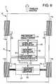
- FIG. 1is a schematic block diagram showing a vehicle mounted with a vehicle control apparatus.
- FIG. 2is a block diagram showing a configuration example of a lateral jerk calculation unit in the vehicle control apparatus shown in FIG. 1 .
- FIGS. 3A and 3Bare graphs provided to explain frequency response characteristics of the transfer function A [Expression 2] shown in FIG. 2 .
- FIGS. 4A and 4Bare graphs provided to explain frequency response characteristics of the transfer function A [Expression 3] shown in FIG. 2 .
- FIGS. 5A , 5 B and 5 Care graphs provided to explain the case where lateral jerk was calculated by a conventional method.
- FIGS. 6A and 6Bare graphs provided to explain the case where the lateral jerk was calculated by using the transfer function A.
- FIG. 7is a functional block diagram showing a configuration example of a breaking and driving force control unit in the vehicle control apparatus shown in FIG. 1 .
- FIG. 8is a flow chart showing a control calculation example to be carried out by a breaking and driving force control unit in the vehicle control apparatus shown in FIG. 1 .
- FIG. 9is a schematic block diagram showing a vehicle where other embodiment of a vehicle control apparatus is applied.
- FIG. 10is a functional block diagram showing a configuration example of a yaw moment control unit in the vehicle control apparatus shown in FIG. 8 .
- FIG. 11is a block diagram showing other configuration example of a lateral jerk calculation unit.
- FIGS. 12A and 12Bare graphs provided to explain frequency response characteristics of the transfer function B [Expression 4] shown in FIG. 11 .
- FIGS. 13A and 13Bare graphs provided to explain frequency response characteristics of the transfer function B [Expression 5] shown in FIG. 11 .
- FIGS. 14A , 14 B and 14 Care graphs provided to explain the case where the lateral jerk was calculated by using the transfer function B.
- FIGS. 15A , 15 B and 15 Care graphs provided to explain the case where the lane change was carried out so rapidly as a vehicle skids, in the case where the lateral jerk is calculated by using the transfer function B.
- FIG. 1is a schematic block diagram showing a vehicle 1 mounted with a vehicle control apparatus.
- a vehicle 1 shown in FIG. 1is a front-wheel-drive car, and is equipped with wheels 11 a , 11 b , 11 c and 11 d at front, rear, left and right of a vehicle, and the rotation driving force from a driving force generation apparatus 17 , which is configured by, for example, a gasoline engine (electrically-driven motor etc. may be acceptable) or transmission etc. is designed to be transmitted to the front wheels 11 a and 11 b .
- a wheel speed sensor 12for detecting rotation speed of the wheel (rotation number), and a break 18 are attached.
- a control unit 5having a built-in microcomputer and built-in electronic circuit parts for carrying out the vehicle control is equipped as a main configuration element of a vehicle control apparatus 3 of the present embodiment, as well as a roll angular velocity sensor 14 is allocated.
- the built-in microcomputer in the control unit 5is well known themselves, and equipped with CPU, ROM, RAM, IO and the like.
- the roll angular velocity sensor 14is one for detecting the roll angular velocity p of the vehicle 1 , and is configured, for example, by a gyro sensor.
- the control unit 5is equipped with a vehicle speed calculation unit 13 , where a wheal speed signal from a wheel speed sensor 12 attached at each of the wheels 11 a , 11 b , 11 c and 11 d is input, a lateral jerk calculation unit 15 , where a roll angular velocity signal from the roll angular velocity sensor 14 is input, and a breaking and driving force control unit 16 for carrying out vehicle control (here, breaking control and driving force control) based on lateral jerk calculated from this lateral jerk calculation unit 15 , as shown in a functional block diagram in FIG. 1 .
- vehicle speed calculation unit 13where a wheal speed signal from a wheel speed sensor 12 attached at each of the wheels 11 a , 11 b , 11 c and 11 d is input
- a lateral jerk calculation unit 15where a roll angular velocity signal from the roll angular velocity sensor 14 is input
- a breaking and driving force control unit 16for carrying out vehicle control (here, breaking control and driving
- the vehicle speed calculation unit 13calculates a vehicle speed V, which is a speed in a travelling direction of the vehicle 1 , based on rotation number of each of the wheels 11 a , 11 b , 11 c and 11 d detected by the wheel speed sensor 12 .
- a vehicle speed Va speed in a travelling direction of the vehicle 1
- Va, Vb, Vc and Vdwhich are the speeds of each of the wheels 11 a , 11 b , 11 c and 11 d in a travelling direction, are calculated by multiplying the radius to angular velocity of each of the wheels 11 a , 11 b , 11 c and 11 d .
- the vehicle speed Vmay be an average value of Va, Vb, Vc and Vd, or may be the lowest value of Va, Vb, Vc and Vd, in consideration of spinning possibility of some of the wheels of 11 a , 11 b , 11 c and 11 d , or may be the second lowest value thereof, or average value of the lowest value and the second lowest value, or the like.
- the lateral jerk calculation unit 15calculates (estimates) the lateral jerk Jy, based on the roll angular velocity p detected by the roll angular velocity sensor 14 . The detail on this lateral jerk calculation unit 15 will be described later.
- the breaking and driving force control unit 16calculates control command value for controlling a driving force generation unit 17 or the break 18 , based on vehicle speed or lateral jerk Jy or the like. The detail on this breaking and driving force control unit 16 will be described later.
- the lateral jerk calculation unit 15calculates, as shown in FIG. 2 , the lateral jerk Jy by using (a vehicle motion model 30 represented by) a transfer function A having the roll angular velocity p as input and the lateral jerk Jy as output.
- hheight from a roll center to center of gravity
- J y ⁇ ( s ) p ⁇ ( s )I x ⁇ s 2 + C x ⁇ s + K x - m s ⁇ gh m s ⁇ h ( 1 )
- the lateral jerk Jymay be calculated from the following Expression 2, by using relatively high frequency f (for example, 100 Hz).
- J y ⁇ ( s ) p ⁇ ( s )I x ⁇ s 2 + C x ⁇ s + K x - m s . ⁇ gh ( 1 / 2 ⁇ ⁇ ⁇ ⁇ f ) 2 ⁇ s 2 + ( 1 / 2 ⁇ ⁇ ⁇ ⁇ f ) ⁇ s + 1 ⁇ 1 m s ⁇ h ( 2 )
- FIGS. 3A and 3Bare graphs showing examples of frequency response characteristics of the transfer function A represented by the Expression 2, taking the frequency as abscissa axis, and the gain and the phase as ordinate axis, respectively.
- the transfer function Ahas the phase lead characteristics, and has the feature in calculating the lateral jerk Jy by a little advancing the phase of roll angular velocity p.
- J y ⁇ ( s ) p ⁇ ( s )T 1 ⁇ s + 1 T 2 ⁇ s + 1 ⁇ K x - m s ⁇ gh m s ⁇ h ( 3 )
- T 1 and T 2 in the Expression 3are set in advance so that the frequency response characteristics up to about 1 Hz becomes close to characteristics shown in FIGS. 3A and 3B .
- FIGS. 4A and 4Bare graphs showing examples of frequency response characteristics of the transfer function A represented by the Expression 3. From FIGS. 4A and 4B , it is understood that the phase lead characteristics is nearly the same as that shown in FIGS. 3A and 3B , up to about 1 Hz.
- FIGS. 5A to 5Cshow the cases according to a conventional method: FIG. 5A shows lateral acceleration sensor value in carrying out the lane change by a passenger car, and FIG. 5B shows value differentiated a signal of FIG. 5A , which is understood to have very large noise.
- a solid line of FIG. 5Cshows a value (calculated value) of lateral jerk determined by passing the differentiated value of FIG. 5B through a low-pass filter, and a broken line of FIG. 5C shows a true value of lateral jerk.
- the calculated value shown by the solid line in FIG. 5Chas a far delayed phase as compared with true value shown by the broken line, and it is understood that accuracy of lateral jerk determined by a conventional method is inferior.
- FIGS. 6A and 6Bare graphs showing the case according to the present embodiment used a transfer function A:
- FIG. 6Ashows, similarly to FIG. 5A , a roll angular velocity sensor value in carrying out the lane change by a passenger car.
- a solid line of FIG. 6Bshows a value (calculated value) of lateral jerk determined by passing the roll angular velocity value of FIG. 6A through the transfer function A having frequency response characteristics shown in FIGS. 4A and 4B
- a broken line of FIG. 6Bshows true value of lateral jerk.
- the calculated value shown by the solid line in FIG. 6Bis nearly coincident with true value shown by the broken line, and it is understood that accuracy of lateral jerk is good.
- the lateral jerk Jyis designed to be calculated by using the transfer function A having roll angular velocity p as input, therefore the lateral jerk having the good accuracy can be obtained.
- FIG. 7is a functional block diagram showing a detailed configuration example of a breaking and driving force control unit 16 for carrying out breaking and driving force control by using the lateral jerk Jy calculated as explained above.
- the breaking and driving force control unit 16is equipped with a driver request vehicle speed calculation unit 31 , an upper limit vehicle speed calculation unit 32 , and a breaking and driving force command value calculation unit 33 .
- the driver request vehicle speed calculation unit 31calculates the vehicle speed V 1 , which is expected in the case where the present breaking and driving force control is not carried out, from the present acceleration opening degree detected by an acceleration pedal sensor (not shown), and engine speed and transmission gear position in a driving force generation apparatus 17 , by using a map set in advance based on experimental results.
- the upper limit vehicle speed calculation unit 32calculates the upper limit value V 2 of the present vehicle speed, which is necessary for stably travelling a curve, by detecting the curvature ⁇ of the curve in a travelling direction (in the case or an arc, the curvature ⁇ becomes an inverse number of radius) and distance L up to the curve, from a car navigation or a camera or the like (not shown).
- an upper limit vehicle speed V 3 in a curveis calculated.
- the upper limit vehicle speed V 3 in a curvebrings the vehicle to upper limit vehicle speed, which is capable of travelling stably in the curve.
- the present upper limit vehicle speed V 2is calculated from upper limit vehicle speed V 3 in a curve and distance L up to the curve, and it is output from an upper limit vehicle speed calculator 32 .
- the present upper limit vehicle speed V 2brings the vehicle speed so as to decelerate smoothly before the curve.
- the present upper limit vehicle speed V 2may be calculated so as to decelerate while changing deceleration degree so as to make the absolute value of forward and afterward jerk small.
- V 2is each calculated based on curvature ⁇ at each position, and the smallest value among them is output from an upper limit vehicle speed calculation unit 32 .
- the breaking and driving force command value calculation unit 33outputs driving force command value for controlling the driving force generation apparatus 17 , and braking command value for controlling the break 18 .
- FIG. 8is a flow chart showing a control calculation example carried out by the breaking and driving force command value calculation unit 33 in the breaking and driving force control unit 16 .
- a difference amount ⁇ V 2is obtained by subtracting the present upper limit vehicle speed V 2 from the present vehicle speed V in the step 101 , and in the next step 102 , it is judged whether the difference amount ⁇ V 2 is positive or not, and in the case of positive, it is forwarded to the step 103 , and in the case of not positive, it is forwarded to the step 104 .
- the step 103outputs the breaking command value in response to the largeness of the difference amount ⁇ V 2 .
- the breaking command valueis set to such value, for example, that provides the stronger breaking with the larger difference amount ⁇ V 2 .
- step 104it is determined whether the break was applied before one cycle, and whether the lateral jerk Jy is near 0 or not. If the brake was applied before one cycle and the lateral jerk Jy is not near 0, it is forwarded to the step 105 . If the brake was not applied before one cycle, or the lateral jerk Jy is near 0, it is forwarded to the step 106 .
- the step 105outputs the breaking command value having the same largeness of breaking force as in one cycle before. It should be noted that in this step 105 , such command value may be output that the breaking force is gradually decreased from one cycle before.
- difference amount ⁇ V 1is obtained by subtracting the present vehicle speed V from driver request vehicle speed V 1 , and in the subsequent step 107 , it is judged whether the difference amount ⁇ V 1 is positive or not, and in the case of positive, it is forwarded to the step 108 , and in the case of not positive, it is forwarded to the step 109 .
- the step 108outputs the breaking command value that the breaking force becomes 0, and the driving force command value in response to largeness of ⁇ V 1 .
- the driving force command valueis set to such value, for example, that provides stronger driving force with the larger ⁇ V 1 .
- the step 109outputs the breaking command value that the breaking force becomes 0, and the driving force command value that driving force becomes 0. It should be noted that, in this step 109 , such command value may be output that the driving force is gradually decreased from one cycle before.
- FIG. 9is a schematic block diagram showing a vehicle 1 ′ where other embodiments of the vehicle control apparatus were applied.
- a vehicle 1 ′ shown in FIG. 9the same reference numbers are given to parts corresponding to each of parts of the vehicle 1 shown in FIG. 1 , to omit the duplicated explanation, and in the explanation below, different points will be provided mainly between the vehicle control apparatus 3 ′ of the present embodiment and the vehicle control apparatus 3 of the above embodiment.
- a control unit 5 ′having a built-in microcomputer and electronic circuit parts for carrying out vehicle control is equipped as a main configuration element of a vehicle control apparatus 3 ′ of the present embodiment, as well as the roll angular velocity sensor 14 is allocated.
- the control unit 5 ′is equipped with, as shown by a functional block diagram in FIG. 9 , a vehicle speed calculation unit 13 , where a wheal speed signal from a wheel speed sensor 12 attached at each of the wheels 11 a , 11 b , 11 c and 11 d is input, and a lateral jerk calculation unit 15 , where a roll angular velocity signal from the roll angular velocity sensor 14 is input, and a yaw moment control unit 19 for carrying out the vehicle control (here, yaw moment control) based on vehicle speed V and lateral jerk Jy or the like calculated by the vehicle speed calculation unit 13 and the lateral jerk calculation unit 15 .
- vehicle speed calculation unit 13where a wheal speed signal from a wheel speed sensor 12 attached at each of the wheels 11 a , 11 b , 11 c and 11 d is input
- a lateral jerk calculation unit 15where a roll angular velocity signal from the roll angular velocity sensor 14 is input
- the yaw moment control unit 19calculates the control command value for controlling a yaw moment generation mechanism 20 , which is built in the driving force generation apparatus 17 ′, based on vehicle speed V or lateral jerk Jy or the like.
- the yaw moment generation mechanism 20is a mechanism to generate yaw moment of the vehicle 1 ′, by generating torque difference between a left rear wheel 1 c and a right rear wheel 1 d .
- As for detail of the yaw moment generation mechanismrefer to, for example, JP-A-2007-139011, if necessary.
- the yaw moment control unit 19is equipped with a yaw angular acceleration calculation unit 41 , which calculates a yaw angular acceleration dr by differentiating a value of yaw angular speed r detected by the yaw angular sensor (not shown), a target yaw angular acceleration calculation unit 42 and a yaw moment command value calculation unit 43 .
- the yaw moment command value calculation unit 43outputs the yaw moment command value for generating the yaw moment in a direction to make close value of yaw angular acceleration dr and the target yaw angular acceleration dr 2 . That is, the yaw moment control unit 19 carries out the control to make close the value obtained by dividing the lateral jerk Jy with vehicle speed V, and the value of yaw angular acceleration.
- the yaw momentis generated in a direction for promoting turning round in starting turning round, and yaw moment is generated in a direction for suppressing turning round in ending turning round, therefore, it is capable of significantly enhancing response property and convergence of vehicle movement, in other words, the quick and correct reaction can be obtained without generation of large blurring of a vehicle to steering of a driver.
- FIG. 11shows the lateral jerk calculation unit 15 ′ with different configuration from a lateral jerk calculation unit 15 of the above embodiment.
- This lateral jerk calculation unit 15 ′calculates the lateral jerk Jy by using (a vehicle motion model 50 expressed by) the transfer function B having steering angle ⁇ detected by a steering angle sensor (not shown) as input and the lateral acceleration as output.
- nsteering gear ratio
- a y ′ ⁇ ( s ) ⁇ ⁇ ( s )′ ⁇ 2 ⁇ I z ⁇ K f ⁇ Vs 2 + 4 ⁇ ll r ⁇ K f ⁇ K r ⁇ s + 4 ⁇ lK f ⁇ K r ⁇ V m ⁇ ⁇ V ⁇ ⁇ I z ⁇ s 2 + ⁇ 2 ⁇ m ⁇ ( I f 2 ⁇ K f + l r 2 ⁇ K r ) + 2 ⁇ I z ⁇ ( K f + K r ) ⁇ ⁇ s + ⁇ 4 ⁇ l 2 ⁇ K f ⁇ K r V - 2 ⁇ m ⁇ ⁇ V ⁇ ( l f ⁇ K f - l r ⁇ K r ) ⁇ ⁇ 1 n ( 4 )
- FIGS. 12A and 12Bshow examples of frequency response characteristics of the transfer function B represented by the Expression 4.
- the transfer function Bis characterized in that characteristics thereof changes with vehicle speed V, and also has low-pass characteristics up to about 1 Hz.
- the transfer function Bmay be calculated by the following Expression 5 may be used, which is a simplified form of the Expression 4.
- a y ′ ⁇ ( s ) ⁇ ⁇ ( s )1 T 0 ⁇ s + 1 ⁇ 4 ⁇ l ⁇ ⁇ K f ⁇ K r ⁇ V 4 ⁇ ⁇ l 2 ⁇ K f ⁇ K r V - 2 ⁇ m ⁇ ⁇ V ⁇ ( l f ⁇ K f - l r ⁇ K r ) ⁇ 1 n ( 5 )
- T 0 of the above Expression 5is designed to be changed in response to vehicle speed V by using a map.
- the mapis set in advance so that the frequency response characteristics up to about 1 Hz becomes close to characteristics shown in FIGS. 12A and 12B .
- FIGS. 13A and 13Bshow examples of frequency response characteristics of the transfer function B represented by the Expression 5. As shown in FIGS. 13A and 13B , it is understood that it has low-pass characteristics up to about 1 Hz, nearly the same as in FIGS. 12A and 12B .
- An estimated lateral acceleration Ay′ calculated by the transfer function Bis processed by sequentially sending to a lateral acceleration limiting unit 52 , a differentiation unit 53 and a low-pass filtering unit 54 , which are equipped in a lateral jerk calculation unit 15 ′, and is taken out as the lateral jerk Jy, as shown in FIG. 11 . That is, in the lateral acceleration limiting unit 52 , it is limited to ⁇ Ay of lateral acceleration Ay detected by a lateral acceleration sensor (not shown) ( ⁇ Ay is, for example, 1 m/sec 2 ).
- the lateral acceleration limiting unit 52outputs (Ay+ ⁇ Ay), when Ay′ is larger than (Ay+ ⁇ Ay); outputs (Ay ⁇ Ay), when Ay′ is smaller than (Ay ⁇ Ay); and outputs Ay′ when Ay′ is none of these.
- Output of this lateral acceleration limiting unit 52is differentiated in the differentiation unit 53 , and the high frequency components of the value output from the differentiation unit 53 are removed in the subsequent low-pass filtering unit 54 .
- the cut-off frequency of the low-pass filtering unit 54is set so that noise is removed as much as possible, and set to frequency (for example, 3 Hz) not to give influence on control.
- the lateral acceleration limiting processing, differentiating processing and filtering processingare designed here to be carried out by a built-in microprocessor in the control unit 5 , however, it may be designed to be carried out by other electronic circuit as its substitution.
- FIG. 14Ashows steering angle sensor value in travelling similarly to in the case shown in FIG. 5 and FIG. 6 .
- the estimated lateral acceleration Ay′ calculated by inputting this steering angle sensor value to the transfer function B,is shown by a solid line in FIG. 14B
- the lateral acceleration sensor value Ayis shown by a broken line in FIG. 14B .
- the estimated lateral acceleration Ay′ shown by the solid line in FIG. 14B and the lateral acceleration sensor value Ay shown by the broken line Ayare nearly the same, and absolute value of difference between them is always within ⁇ Ay (1 m/s 2 ), therefore the output of the lateral acceleration limiting unit 52 is always the same as Ay′.
- FIG. 14Cshows a signal obtained by differentiating the output of the lateral acceleration limiting unit 52 by the differentiation unit 53 and after passing it through the low-pass filtering unit 54 , that is, shows a value (calculated value) of lateral jerk calculated by the lateral jerk calculation unit 15 ′ of the present embodiment, and the broken line of FIG. 14C is true value of lateral jerk.
- the calculated value shown by the solid line in FIG. 14Cis nearly coincident with true value shown by the broken line, and thus it is understood that the lateral jerk determined by the lateral jerk calculation unit 15 ′ of the present embodiment has a good accuracy.
- FIG. 15Ashows a steering angle sensor value in the case where the lane change was carried out so rapidly as a vehicle skids; a solid line of FIG. 15B shows the estimated lateral acceleration Ay′ calculated by inputting a signal (steering angle sensor value) of FIG. 15A to the transfer function B; and a broken line of FIG. 15B is the lateral acceleration sensor value Ay.
- FIG. 15Cshows a signal obtained by differentiating the output of lateral acceleration limiting unit 52 by the differentiation unit 53 and after passing it through the low-pass filtering unit 54 , that is, shows the value (calculated value) of lateral jerk determined by the lateral jerk calculation unit 15 ′ of the present embodiment, and the broken line of FIG. 15C is the true value of lateral jerk.
- the calculated value shown by the solid line in FIG. 15Cis nearly coincident with true value shown by the broken line, and thus it is understood that the lateral jerk determined by the lateral jerk calculation unit 15 ′ of the present embodiment has a good accuracy.
- the lateral jerkcan be calculated with high accuracy.
- the control to end deceleration or start accelerationcan be carried out adequately during a period when value of lateral jerk is near zero, and the control of acceleration and deceleration can be carried out without generation of uncomfortable feeling to a driver.
- the yaw momentcan be generated in a direction for promoting turning round (revolving) in starting turning round (revolving), and yaw moment can be generated in a direction for suppressing turning round (revolving) in ending turning round (revolving), therefore, it is capable of significantly enhancing response property and convergence of vehicle movement.
Landscapes
- Engineering & Computer Science (AREA)
- Automation & Control Theory (AREA)
- Transportation (AREA)
- Mechanical Engineering (AREA)
- Physics & Mathematics (AREA)
- Mathematical Physics (AREA)
- Regulating Braking Force (AREA)
- Control Of Driving Devices And Active Controlling Of Vehicle (AREA)
- Vehicle Body Suspensions (AREA)
Abstract
Description
Claims (4)
Applications Claiming Priority (2)
| Application Number | Priority Date | Filing Date | Title |
|---|---|---|---|
| JP2007-280808 | 2007-10-29 | ||
| JP2007280808AJP4997065B2 (en) | 2007-10-29 | 2007-10-29 | Vehicle control device |
Publications (2)
| Publication Number | Publication Date |
|---|---|
| US20090112404A1 US20090112404A1 (en) | 2009-04-30 |
| US7853366B2true US7853366B2 (en) | 2010-12-14 |
Family
ID=40280798
Family Applications (1)
| Application Number | Title | Priority Date | Filing Date |
|---|---|---|---|
| US12/259,948Expired - Fee RelatedUS7853366B2 (en) | 2007-10-29 | 2008-10-28 | Vehicle control apparatus |
Country Status (3)
| Country | Link |
|---|---|
| US (1) | US7853366B2 (en) |
| EP (1) | EP2055600B1 (en) |
| JP (1) | JP4997065B2 (en) |
Cited By (7)
| Publication number | Priority date | Publication date | Assignee | Title |
|---|---|---|---|---|
| US20110082627A1 (en)* | 2009-10-05 | 2011-04-07 | Tesla Motors, Inc. | Morphing Vehicle User Interface |
| US20110082616A1 (en)* | 2009-10-05 | 2011-04-07 | Tesla Motors, Inc. | Vehicle User Interface with Proximity Activation |
| US20110082619A1 (en)* | 2009-10-05 | 2011-04-07 | Tesla Motors, Inc. | Adaptive Soft Buttons for a Vehicle User Interface |
| US20110082618A1 (en)* | 2009-10-05 | 2011-04-07 | Tesla Motors, Inc. | Adaptive Audible Feedback Cues for a Vehicle User Interface |
| US20120209489A1 (en)* | 2009-10-23 | 2012-08-16 | Hitachi Automotive Systems, Ltd. | Vehicle Movement Controller |
| CN104571100A (en)* | 2015-01-28 | 2015-04-29 | 北京控制工程研究所 | Non-minimum-phase hypersonic vehicle control method |
| US10407035B1 (en) | 2016-08-03 | 2019-09-10 | Apple Inc. | Integrated chassis control |
Families Citing this family (11)
| Publication number | Priority date | Publication date | Assignee | Title |
|---|---|---|---|---|
| JP5143103B2 (en)* | 2009-09-30 | 2013-02-13 | 日立オートモティブシステムズ株式会社 | Vehicle motion control device |
| JP5690176B2 (en)* | 2011-03-11 | 2015-03-25 | 日立オートモティブシステムズ株式会社 | Inertial sensor |
| WO2012153367A1 (en)* | 2011-05-11 | 2012-11-15 | 日立オートモティブシステムズ株式会社 | Vehicle operation control device and vehicle operation control system |
| KR20130044727A (en)* | 2011-10-24 | 2013-05-03 | 현대모비스 주식회사 | Method for calculating request command of wheel alignment apparatus used motor driven power steering |
| JP2014148182A (en) | 2013-01-31 | 2014-08-21 | Hitachi Automotive Systems Ltd | Travel control unit of vehicle |
| JP6229376B2 (en)* | 2013-09-02 | 2017-11-15 | トヨタ自動車株式会社 | Vehicle driving situation determination device and vehicle driving situation determination method |
| JP2016182959A (en)* | 2016-06-30 | 2016-10-20 | 日立オートモティブシステムズ株式会社 | Motion control system of vehicle |
| US20200086885A1 (en) | 2017-06-15 | 2020-03-19 | Hitachi Automotive Systems, Ltd. | Vehicle Control Device |
| JP6568560B2 (en)* | 2017-09-15 | 2019-08-28 | 株式会社Subaru | Vehicle travel control device |
| JP6506812B2 (en)* | 2017-10-06 | 2019-04-24 | 日立オートモティブシステムズ株式会社 | Vehicle motion control device and motion control program |
| JP7150001B2 (en)* | 2020-12-28 | 2022-10-07 | 本田技研工業株式会社 | vehicle controller |
Citations (50)
| Publication number | Priority date | Publication date | Assignee | Title |
|---|---|---|---|---|
| JPH01160719A (en) | 1987-09-04 | 1989-06-23 | Toyota Motor Corp | Electronically controlled suspension device |
| EP0453771A2 (en) | 1990-04-27 | 1991-10-30 | Toyota Jidosha Kabushiki Kaisha | Roll control system in vehicle admissive of counter steering |
| US5088762A (en)* | 1989-09-29 | 1992-02-18 | Nissan Motor Company, Limited | Control system for active suspension which distributes load according to lateral acceleration |
| DE4221059A1 (en) | 1991-06-26 | 1993-01-21 | Naldec Kk | Control system for active suspension of vehicle - has lateral motion sensors with processing to determine if cornering is stable |
| US5895433A (en)* | 1996-05-23 | 1999-04-20 | General Motors Corporation | Vehicle chassis system control method and apparatus |
| US5925084A (en)* | 1995-12-27 | 1999-07-20 | Toyota Jidosha Kabushiki Kaisha | Attitude-supporting apparatus mounted on vehicle for sustaining attitude of passenger and method of sustaining attitude of passenger |
| US6038495A (en)* | 1998-02-06 | 2000-03-14 | Delco Electronics Corporation | Vehicle rollover sensing using short-term integration |
| US6175792B1 (en)* | 1998-02-03 | 2001-01-16 | Trw Inc. | Apparatus and method for improving dynamic response of an active roll control vehicle suspension system |
| US6282474B1 (en)* | 2000-06-04 | 2001-08-28 | Ford Global Technologies, Inc. | Method and apparatus for detecting rollover of an automotive vehicle |
| US6292759B1 (en)* | 1998-11-19 | 2001-09-18 | Delphi Technologies, Inc. | Vehicle attitude angle estimation using sensed signal blending |
| US6295493B1 (en)* | 1997-09-10 | 2001-09-25 | Nissan Motor Co., Ltd. | Vehicle roll rigidity control device |
| US20020040268A1 (en)* | 2000-09-29 | 2002-04-04 | Toyota Jidosha Kabushiki Kaisha | Apparatus for detecting rotational state of wheel |
| US20020056582A1 (en)* | 2000-09-25 | 2002-05-16 | Chubb Erik Christopher | Wheel lift identification for an automotive vehicle |
| US20020075139A1 (en)* | 2000-12-14 | 2002-06-20 | Toyota Jidosha Kabushiki Kaisha | Vehicle control apparatus and vehicle control method |
| US6415215B1 (en)* | 2000-02-23 | 2002-07-02 | Koyo Seiko Co., Ltd. | Vehicle attitude control apparatus |
| US20020087235A1 (en)* | 2000-12-28 | 2002-07-04 | Toyota Jidosha Kabushiki Kaisha | Rollover determining apparatus and methods |
| US20020099486A1 (en)* | 2001-01-19 | 2002-07-25 | Toyota Jidosha Kabushiki Kaisha | Systems and methods for controlling a vehicle-occupant protecting apparatus |
| US20020096003A1 (en)* | 2001-01-23 | 2002-07-25 | Toyota Jidosha Kabushiki Kaisha | Running condition control system for vehicle and method |
| US20020139599A1 (en)* | 2001-02-21 | 2002-10-03 | Jianbo Lu | Rollover stability control for an automotive vehicle using rear wheel steering and brake control |
| US6477480B1 (en)* | 2000-11-15 | 2002-11-05 | Ford Global Technologies, Inc. | Method and apparatus for determining lateral velocity of a vehicle |
| US20020173882A1 (en)* | 1999-09-06 | 2002-11-21 | Honda Giken Kogyo Kabushiki Kaisha | System for detecting inclination angle of vehicle body |
| US6529803B2 (en)* | 1999-12-21 | 2003-03-04 | Ford Global Technologies, Inc. | Roll over stability control for an automotive vehicle having rear wheel steering |
| US6584388B2 (en)* | 2001-11-08 | 2003-06-24 | Delphi Technologies, Inc. | Adaptive rollover detection apparatus and method |
| EP1386803A1 (en) | 2002-08-01 | 2004-02-04 | Ford Global Technologies, LLC | Wheel lifted and grounded identification for an automotive vehicle |
| US20040024509A1 (en)* | 2002-08-05 | 2004-02-05 | Salib Albert Chenouda | System and method for determining an amount of control for operating a rollover control system |
| US20040024505A1 (en)* | 2002-08-05 | 2004-02-05 | Salib Albert Chenouda | System and method for operating a rollover control system in a transition to a rollover condition |
| US20040162654A1 (en) | 2002-08-01 | 2004-08-19 | Jianbo Lu | System and method for determining a wheel departure angle for a rollover control system with respect to road roll rate and loading misalignment |
| JP2004243813A (en) | 2003-02-12 | 2004-09-02 | Honda Motor Co Ltd | Vehicle steering control device |
| US20040176893A1 (en)* | 2003-03-04 | 2004-09-09 | Denso Corporation | Apparatus and method for activating occupant restraint device |
| US20040193352A1 (en)* | 2003-03-31 | 2004-09-30 | Sentaro Ito | Control device for a vehicle |
| US20040199317A1 (en)* | 2003-02-25 | 2004-10-07 | Yoshihisa Ogata | Apparatus for detecting rollover of vehicle and apparatus for activating occupant protective device |
| US20040254710A1 (en)* | 2003-06-12 | 2004-12-16 | Nissan Motor Co., Ltd. | Vehicle rollover detection method and apparatus |
| US20050004730A1 (en)* | 2003-07-03 | 2005-01-06 | Mitsubishi Denki Kabushiki Kaisha | Vehicle-rollover detecting apparatus and vehicle-rollover detecting method |
| US20050027426A1 (en) | 2003-07-30 | 2005-02-03 | Toshihisa Kato | Vehicle motion control device |
| EP1514754A2 (en) | 1999-07-21 | 2005-03-16 | Denso Corporation | Slip angle estimating method and system for a vehicle |
| US20050080544A1 (en)* | 2003-10-08 | 2005-04-14 | Mitsubishi Denki Kabushiki Kaisha | Rollover determination apparatus for vehicles |
| US20050149240A1 (en)* | 2004-01-07 | 2005-07-07 | Tseng Hongtei E. | Attitude sensing system for an automotive vehicle relative to the road |
| US20050159864A1 (en) | 2004-01-16 | 2005-07-21 | Denso Corporation | Rollover judging device |
| US20050177296A1 (en) | 1999-12-21 | 2005-08-11 | Todd Brown | Roll over stability control for an automotive vehicle |
| EP1568521A2 (en) | 2004-02-26 | 2005-08-31 | Aisin Seiki Kabushiki Kaisha | Stabilizer control apparatus |
| US20050222728A1 (en)* | 2004-04-01 | 2005-10-06 | Hac Aleksander B | Feedforward control of motor vehicle roll angle |
| US20050256628A1 (en)* | 2002-08-05 | 2005-11-17 | Salib Albert C | System and method for operating a rollover control system during an elevated condition |
| US20050257981A1 (en)* | 2001-07-24 | 2005-11-24 | Motomi Iyoda | Rollover determination system and method |
| US20050273240A1 (en)* | 2004-06-02 | 2005-12-08 | Brown Todd A | System and method for determining desired yaw rate and lateral velocity for use in a vehicle dynamic control system |
| US20060069489A1 (en)* | 2004-09-27 | 2006-03-30 | Chen Hsien H | Motor vehicle control using a dynamic feedforward approach |
| US20060293826A1 (en)* | 2005-05-13 | 2006-12-28 | Samsung Electronics Co., Ltd. | Apparatus and method for measuring speed of a moving object |
| JP2007112367A (en) | 2005-10-24 | 2007-05-10 | Hitachi Ltd | Vehicle tire condition detection method and vehicle tire condition detection device |
| JP2007139011A (en) | 2005-11-16 | 2007-06-07 | Hitachi Ltd | Axle torque generator |
| US20070162202A1 (en) | 2006-01-12 | 2007-07-12 | Moshchuk Nikolai K | Roll stability indicator for vehicle rollover control |
| JP2007290650A (en) | 2006-04-27 | 2007-11-08 | Hitachi Ltd | Vehicle motion control device |
Family Cites Families (7)
| Publication number | Priority date | Publication date | Assignee | Title |
|---|---|---|---|---|
| JP2594126B2 (en)* | 1987-09-04 | 1997-03-26 | トヨタ自動車株式会社 | Electronic suspension system |
| JP3275320B2 (en)* | 1991-04-25 | 2002-04-15 | トヨタ自動車株式会社 | Wheel slip condition evaluation device |
| JP3124633B2 (en)* | 1992-08-05 | 2001-01-15 | 株式会社ユニシアジェックス | Vehicle suspension system |
| JP3608442B2 (en)* | 1999-07-15 | 2005-01-12 | トヨタ自動車株式会社 | Vehicle damping coefficient control device |
| US6789002B1 (en)* | 2003-05-19 | 2004-09-07 | Delphi Technologies, Inc. | Determination of vehicle payload condition |
| US7715965B2 (en)* | 2004-10-15 | 2010-05-11 | Ford Global Technologies | System and method for qualitatively determining vehicle loading conditions |
| JP4703219B2 (en)* | 2005-03-04 | 2011-06-15 | 三菱電機株式会社 | Image display device |
- 2007
- 2007-10-29JPJP2007280808Apatent/JP4997065B2/enactiveActive
- 2008
- 2008-10-27EPEP08018750Apatent/EP2055600B1/ennot_activeNot-in-force
- 2008-10-28USUS12/259,948patent/US7853366B2/ennot_activeExpired - Fee Related
Patent Citations (55)
| Publication number | Priority date | Publication date | Assignee | Title |
|---|---|---|---|---|
| JPH01160719A (en) | 1987-09-04 | 1989-06-23 | Toyota Motor Corp | Electronically controlled suspension device |
| JP2621390B2 (en) | 1987-09-04 | 1997-06-18 | トヨタ自動車株式会社 | Electronic suspension system |
| US5088762A (en)* | 1989-09-29 | 1992-02-18 | Nissan Motor Company, Limited | Control system for active suspension which distributes load according to lateral acceleration |
| EP0453771A2 (en) | 1990-04-27 | 1991-10-30 | Toyota Jidosha Kabushiki Kaisha | Roll control system in vehicle admissive of counter steering |
| DE4221059A1 (en) | 1991-06-26 | 1993-01-21 | Naldec Kk | Control system for active suspension of vehicle - has lateral motion sensors with processing to determine if cornering is stable |
| US5519611A (en) | 1991-06-26 | 1996-05-21 | Naldec Corporation | Suspension control apparatus for vehicle |
| US5925084A (en)* | 1995-12-27 | 1999-07-20 | Toyota Jidosha Kabushiki Kaisha | Attitude-supporting apparatus mounted on vehicle for sustaining attitude of passenger and method of sustaining attitude of passenger |
| US5895433A (en)* | 1996-05-23 | 1999-04-20 | General Motors Corporation | Vehicle chassis system control method and apparatus |
| US6295493B1 (en)* | 1997-09-10 | 2001-09-25 | Nissan Motor Co., Ltd. | Vehicle roll rigidity control device |
| US6175792B1 (en)* | 1998-02-03 | 2001-01-16 | Trw Inc. | Apparatus and method for improving dynamic response of an active roll control vehicle suspension system |
| US6038495A (en)* | 1998-02-06 | 2000-03-14 | Delco Electronics Corporation | Vehicle rollover sensing using short-term integration |
| US6292759B1 (en)* | 1998-11-19 | 2001-09-18 | Delphi Technologies, Inc. | Vehicle attitude angle estimation using sensed signal blending |
| EP1514754A2 (en) | 1999-07-21 | 2005-03-16 | Denso Corporation | Slip angle estimating method and system for a vehicle |
| US20020173882A1 (en)* | 1999-09-06 | 2002-11-21 | Honda Giken Kogyo Kabushiki Kaisha | System for detecting inclination angle of vehicle body |
| US20050177296A1 (en) | 1999-12-21 | 2005-08-11 | Todd Brown | Roll over stability control for an automotive vehicle |
| US6529803B2 (en)* | 1999-12-21 | 2003-03-04 | Ford Global Technologies, Inc. | Roll over stability control for an automotive vehicle having rear wheel steering |
| US6415215B1 (en)* | 2000-02-23 | 2002-07-02 | Koyo Seiko Co., Ltd. | Vehicle attitude control apparatus |
| US6282474B1 (en)* | 2000-06-04 | 2001-08-28 | Ford Global Technologies, Inc. | Method and apparatus for detecting rollover of an automotive vehicle |
| US20020056582A1 (en)* | 2000-09-25 | 2002-05-16 | Chubb Erik Christopher | Wheel lift identification for an automotive vehicle |
| US20020040268A1 (en)* | 2000-09-29 | 2002-04-04 | Toyota Jidosha Kabushiki Kaisha | Apparatus for detecting rotational state of wheel |
| US6477480B1 (en)* | 2000-11-15 | 2002-11-05 | Ford Global Technologies, Inc. | Method and apparatus for determining lateral velocity of a vehicle |
| US20020075139A1 (en)* | 2000-12-14 | 2002-06-20 | Toyota Jidosha Kabushiki Kaisha | Vehicle control apparatus and vehicle control method |
| US20020087235A1 (en)* | 2000-12-28 | 2002-07-04 | Toyota Jidosha Kabushiki Kaisha | Rollover determining apparatus and methods |
| US20020099486A1 (en)* | 2001-01-19 | 2002-07-25 | Toyota Jidosha Kabushiki Kaisha | Systems and methods for controlling a vehicle-occupant protecting apparatus |
| US20020096003A1 (en)* | 2001-01-23 | 2002-07-25 | Toyota Jidosha Kabushiki Kaisha | Running condition control system for vehicle and method |
| US20020139599A1 (en)* | 2001-02-21 | 2002-10-03 | Jianbo Lu | Rollover stability control for an automotive vehicle using rear wheel steering and brake control |
| US20050257981A1 (en)* | 2001-07-24 | 2005-11-24 | Motomi Iyoda | Rollover determination system and method |
| US6584388B2 (en)* | 2001-11-08 | 2003-06-24 | Delphi Technologies, Inc. | Adaptive rollover detection apparatus and method |
| EP1386803A1 (en) | 2002-08-01 | 2004-02-04 | Ford Global Technologies, LLC | Wheel lifted and grounded identification for an automotive vehicle |
| US7079928B2 (en)* | 2002-08-01 | 2006-07-18 | Ford Global Technologies, Llc | System and method for determining a wheel departure angle for a rollover control system with respect to road roll rate and loading misalignment |
| US20040162654A1 (en) | 2002-08-01 | 2004-08-19 | Jianbo Lu | System and method for determining a wheel departure angle for a rollover control system with respect to road roll rate and loading misalignment |
| US20040024509A1 (en)* | 2002-08-05 | 2004-02-05 | Salib Albert Chenouda | System and method for determining an amount of control for operating a rollover control system |
| US20040024505A1 (en)* | 2002-08-05 | 2004-02-05 | Salib Albert Chenouda | System and method for operating a rollover control system in a transition to a rollover condition |
| US20050256628A1 (en)* | 2002-08-05 | 2005-11-17 | Salib Albert C | System and method for operating a rollover control system during an elevated condition |
| US20050246085A1 (en)* | 2002-08-05 | 2005-11-03 | Salib Albert C | System and method for operating a rollover control system in a transition to a rollover condition |
| JP2004243813A (en) | 2003-02-12 | 2004-09-02 | Honda Motor Co Ltd | Vehicle steering control device |
| US20040199317A1 (en)* | 2003-02-25 | 2004-10-07 | Yoshihisa Ogata | Apparatus for detecting rollover of vehicle and apparatus for activating occupant protective device |
| US20040176893A1 (en)* | 2003-03-04 | 2004-09-09 | Denso Corporation | Apparatus and method for activating occupant restraint device |
| US20040193352A1 (en)* | 2003-03-31 | 2004-09-30 | Sentaro Ito | Control device for a vehicle |
| US20040254710A1 (en)* | 2003-06-12 | 2004-12-16 | Nissan Motor Co., Ltd. | Vehicle rollover detection method and apparatus |
| US20050004730A1 (en)* | 2003-07-03 | 2005-01-06 | Mitsubishi Denki Kabushiki Kaisha | Vehicle-rollover detecting apparatus and vehicle-rollover detecting method |
| US20050027426A1 (en) | 2003-07-30 | 2005-02-03 | Toshihisa Kato | Vehicle motion control device |
| US20050080544A1 (en)* | 2003-10-08 | 2005-04-14 | Mitsubishi Denki Kabushiki Kaisha | Rollover determination apparatus for vehicles |
| US20050149240A1 (en)* | 2004-01-07 | 2005-07-07 | Tseng Hongtei E. | Attitude sensing system for an automotive vehicle relative to the road |
| US20050159864A1 (en) | 2004-01-16 | 2005-07-21 | Denso Corporation | Rollover judging device |
| US20050192728A1 (en)* | 2004-02-26 | 2005-09-01 | Aisin Seiki Kabushiki Kaisha | Stabilizer control apparatus |
| EP1568521A2 (en) | 2004-02-26 | 2005-08-31 | Aisin Seiki Kabushiki Kaisha | Stabilizer control apparatus |
| US20050222728A1 (en)* | 2004-04-01 | 2005-10-06 | Hac Aleksander B | Feedforward control of motor vehicle roll angle |
| US20050273240A1 (en)* | 2004-06-02 | 2005-12-08 | Brown Todd A | System and method for determining desired yaw rate and lateral velocity for use in a vehicle dynamic control system |
| US20060069489A1 (en)* | 2004-09-27 | 2006-03-30 | Chen Hsien H | Motor vehicle control using a dynamic feedforward approach |
| US20060293826A1 (en)* | 2005-05-13 | 2006-12-28 | Samsung Electronics Co., Ltd. | Apparatus and method for measuring speed of a moving object |
| JP2007112367A (en) | 2005-10-24 | 2007-05-10 | Hitachi Ltd | Vehicle tire condition detection method and vehicle tire condition detection device |
| JP2007139011A (en) | 2005-11-16 | 2007-06-07 | Hitachi Ltd | Axle torque generator |
| US20070162202A1 (en) | 2006-01-12 | 2007-07-12 | Moshchuk Nikolai K | Roll stability indicator for vehicle rollover control |
| JP2007290650A (en) | 2006-04-27 | 2007-11-08 | Hitachi Ltd | Vehicle motion control device |
Non-Patent Citations (3)
| Title |
|---|
| Abe Masato, "Motion and Control of an Automobile", 2ND Edition, ages 52, 93 and 171 from Sanaido, (Four (4) pages). |
| European Search Report dated May 25, 2009 (Nine (9) pages). |
| Office Action dated May 19, 2010 (Five (5) pages). |
Cited By (12)
| Publication number | Priority date | Publication date | Assignee | Title |
|---|---|---|---|---|
| US20110082627A1 (en)* | 2009-10-05 | 2011-04-07 | Tesla Motors, Inc. | Morphing Vehicle User Interface |
| US20110082616A1 (en)* | 2009-10-05 | 2011-04-07 | Tesla Motors, Inc. | Vehicle User Interface with Proximity Activation |
| US20110082619A1 (en)* | 2009-10-05 | 2011-04-07 | Tesla Motors, Inc. | Adaptive Soft Buttons for a Vehicle User Interface |
| US20110082618A1 (en)* | 2009-10-05 | 2011-04-07 | Tesla Motors, Inc. | Adaptive Audible Feedback Cues for a Vehicle User Interface |
| US8818624B2 (en) | 2009-10-05 | 2014-08-26 | Tesla Motors, Inc. | Adaptive soft buttons for a vehicle user interface |
| US8892299B2 (en) | 2009-10-05 | 2014-11-18 | Tesla Motors, Inc. | Vehicle user interface with proximity activation |
| US9079498B2 (en) | 2009-10-05 | 2015-07-14 | Tesla Motors, Inc. | Morphing vehicle user interface |
| US20120209489A1 (en)* | 2009-10-23 | 2012-08-16 | Hitachi Automotive Systems, Ltd. | Vehicle Movement Controller |
| CN104571100A (en)* | 2015-01-28 | 2015-04-29 | 北京控制工程研究所 | Non-minimum-phase hypersonic vehicle control method |
| CN104571100B (en)* | 2015-01-28 | 2017-06-27 | 北京控制工程研究所 | A non-minimum phase hypersonic vehicle control method |
| US10407035B1 (en) | 2016-08-03 | 2019-09-10 | Apple Inc. | Integrated chassis control |
| US10919520B1 (en) | 2016-08-03 | 2021-02-16 | Apple Inc. | Integrated chassis control |
Also Published As
| Publication number | Publication date |
|---|---|
| EP2055600B1 (en) | 2013-01-16 |
| JP4997065B2 (en) | 2012-08-08 |
| EP2055600A3 (en) | 2009-06-24 |
| EP2055600A2 (en) | 2009-05-06 |
| JP2009107447A (en) | 2009-05-21 |
| US20090112404A1 (en) | 2009-04-30 |
Similar Documents
| Publication | Publication Date | Title |
|---|---|---|
| US7853366B2 (en) | Vehicle control apparatus | |
| JP4161923B2 (en) | Vehicle stabilization control system | |
| EP2433840B1 (en) | Motion control unit for vehicle based on jerk information | |
| CN111483467B (en) | A vehicle control method and device | |
| JP3946294B2 (en) | Braking force control device | |
| JP2002145037A (en) | Road surface friction coefficient estimation device for vehicles | |
| JP2008081006A (en) | Vehicle travel control device | |
| KR102164606B1 (en) | Lateral control parameter correction apparatus and method for autonomous vehicle | |
| US20160288787A1 (en) | Method for predicting the travel path of a motor vehicle and prediction apparatus | |
| JP4277907B2 (en) | Driving control device for automobile | |
| JP6577850B2 (en) | Vehicle control apparatus and vehicle control method | |
| JP2011105096A (en) | Vehicle dynamics control device | |
| JP2000292316A (en) | Estimation arithmetic device of center-of-gravity height of vehicle | |
| US20220227338A1 (en) | Vehicle control system | |
| JP3271956B2 (en) | Road surface friction coefficient estimation device for vehicles | |
| JP2022021309A (en) | Method for supporting driver of ego-vehicle when passing through curve ahead | |
| JP2010260544A (en) | Vehicle motion control method using jerk information | |
| CN110949373B (en) | Vehicle control method and system and vehicle | |
| JP2008260439A (en) | Vehicle behavior control apparatus and vehicle behavior control method | |
| US12358505B2 (en) | Vehicle control system | |
| US11840210B2 (en) | Vehicle control system | |
| EP4516566A1 (en) | Control device and program | |
| JP2019098753A (en) | Self-driving device and self-driving method | |
| JPH11117784A (en) | Vehicular position control device | |
| WO2024252717A1 (en) | Vehicle control device and vehicle control method |
Legal Events
| Date | Code | Title | Description |
|---|---|---|---|
| AS | Assignment | Owner name:HITACHI, LTD., JAPAN Free format text:ASSIGNMENT OF ASSIGNORS INTEREST;ASSIGNORS:IMURA, SHINYA;YOKOYAMA, ATSUSHI;TAKAHASHI, JUNYA;AND OTHERS;REEL/FRAME:022304/0435;SIGNING DATES FROM 20080905 TO 20080911 Owner name:HITACHI, LTD., JAPAN Free format text:ASSIGNMENT OF ASSIGNORS INTEREST;ASSIGNORS:IMURA, SHINYA;YOKOYAMA, ATSUSHI;TAKAHASHI, JUNYA;AND OTHERS;SIGNING DATES FROM 20080905 TO 20080911;REEL/FRAME:022304/0435 | |
| FEPP | Fee payment procedure | Free format text:PAYOR NUMBER ASSIGNED (ORIGINAL EVENT CODE: ASPN); ENTITY STATUS OF PATENT OWNER: LARGE ENTITY | |
| STCF | Information on status: patent grant | Free format text:PATENTED CASE | |
| FPAY | Fee payment | Year of fee payment:4 | |
| MAFP | Maintenance fee payment | Free format text:PAYMENT OF MAINTENANCE FEE, 8TH YEAR, LARGE ENTITY (ORIGINAL EVENT CODE: M1552) Year of fee payment:8 | |
| AS | Assignment | Owner name:HITACHI AUTOMOTIVE SYSTEMS, LTD., JAPAN Free format text:DEMERGER;ASSIGNOR:HITACHI, LTD.;REEL/FRAME:058960/0001 Effective date:20090701 | |
| AS | Assignment | Owner name:HITACHI ASTEMO, LTD., JAPAN Free format text:CHANGE OF NAME;ASSIGNOR:HITACHI AUTOMOTIVE SYSTEMS, LTD.;REEL/FRAME:058481/0935 Effective date:20210101 | |
| FEPP | Fee payment procedure | Free format text:MAINTENANCE FEE REMINDER MAILED (ORIGINAL EVENT CODE: REM.); ENTITY STATUS OF PATENT OWNER: LARGE ENTITY | |
| LAPS | Lapse for failure to pay maintenance fees | Free format text:PATENT EXPIRED FOR FAILURE TO PAY MAINTENANCE FEES (ORIGINAL EVENT CODE: EXP.); ENTITY STATUS OF PATENT OWNER: LARGE ENTITY | |
| STCH | Information on status: patent discontinuation | Free format text:PATENT EXPIRED DUE TO NONPAYMENT OF MAINTENANCE FEES UNDER 37 CFR 1.362 | |
| FP | Lapsed due to failure to pay maintenance fee | Effective date:20221214 |