US7853332B2 - Lead electrode for use in an MRI-safe implantable medical device - Google Patents
Lead electrode for use in an MRI-safe implantable medical deviceDownload PDFInfo
- Publication number
- US7853332B2 US7853332B2US11/117,882US11788205AUS7853332B2US 7853332 B2US7853332 B2US 7853332B2US 11788205 AUS11788205 AUS 11788205AUS 7853332 B2US7853332 B2US 7853332B2
- Authority
- US
- United States
- Prior art keywords
- section
- lead
- ring
- patient
- electrode
- Prior art date
- Legal status (The legal status is an assumption and is not a legal conclusion. Google has not performed a legal analysis and makes no representation as to the accuracy of the status listed.)
- Active, expires
Links
- 230000000638stimulationEffects0.000claimsdescription67
- 239000003990capacitorSubstances0.000claimsdescription24
- 238000002513implantationMethods0.000claimsdescription7
- 238000002560therapeutic procedureMethods0.000claimsdescription5
- 230000008878couplingEffects0.000claimsdescription4
- 238000010168coupling processMethods0.000claimsdescription4
- 238000005859coupling reactionMethods0.000claimsdescription4
- 238000002595magnetic resonance imagingMethods0.000description27
- 208000027418Wounds and injuryDiseases0.000description11
- 210000000278spinal cordAnatomy0.000description11
- 238000000034methodMethods0.000description7
- 210000001519tissueAnatomy0.000description7
- 239000004020conductorSubstances0.000description6
- 239000003989dielectric materialSubstances0.000description6
- 210000004556brainAnatomy0.000description5
- 239000000463materialSubstances0.000description4
- 229910052751metalInorganic materials0.000description4
- 239000002184metalSubstances0.000description4
- 230000003068static effectEffects0.000description4
- 208000002193PainDiseases0.000description3
- 230000005672electromagnetic fieldEffects0.000description3
- 239000012530fluidSubstances0.000description3
- 238000010438heat treatmentMethods0.000description3
- 238000003384imaging methodMethods0.000description3
- 229920000642polymerPolymers0.000description3
- 230000002829reductive effectEffects0.000description3
- KDLHZDBZIXYQEI-UHFFFAOYSA-NPalladiumChemical compound[Pd]KDLHZDBZIXYQEI-UHFFFAOYSA-N0.000description2
- 208000018737Parkinson diseaseDiseases0.000description2
- 239000004952PolyamideSubstances0.000description2
- 210000001015abdomenAnatomy0.000description2
- 238000000429assemblyMethods0.000description2
- 230000000712assemblyEffects0.000description2
- 238000010276constructionMethods0.000description2
- 230000003247decreasing effectEffects0.000description2
- 238000003745diagnosisMethods0.000description2
- 230000000694effectsEffects0.000description2
- 239000007943implantSubstances0.000description2
- 230000003993interactionEffects0.000description2
- 230000001537neural effectEffects0.000description2
- BASFCYQUMIYNBI-UHFFFAOYSA-NplatinumChemical compound[Pt]BASFCYQUMIYNBI-UHFFFAOYSA-N0.000description2
- 229920002647polyamidePolymers0.000description2
- 230000008569processEffects0.000description2
- 238000001356surgical procedureMethods0.000description2
- 206010010904ConvulsionDiseases0.000description1
- 208000033999Device damageDiseases0.000description1
- 101100437784Drosophila melanogaster bocks geneProteins0.000description1
- 206010021639IncontinenceDiseases0.000description1
- 208000016285Movement diseaseDiseases0.000description1
- 208000012902Nervous system diseaseDiseases0.000description1
- 208000025966Neurological diseaseDiseases0.000description1
- 239000004743PolypropyleneSubstances0.000description1
- 239000004809TeflonSubstances0.000description1
- 229920006362Teflon®Polymers0.000description1
- 230000002411adverseEffects0.000description1
- 229910045601alloyInorganic materials0.000description1
- 239000000956alloySubstances0.000description1
- 210000001217buttockAnatomy0.000description1
- 239000003985ceramic capacitorSubstances0.000description1
- 229910010293ceramic materialInorganic materials0.000description1
- 230000001010compromised effectEffects0.000description1
- 229920001940conductive polymerPolymers0.000description1
- 230000006378damageEffects0.000description1
- 230000001419dependent effectEffects0.000description1
- 230000002996emotional effectEffects0.000description1
- 206010015037epilepsyDiseases0.000description1
- 210000000609gangliaAnatomy0.000description1
- PCHJSUWPFVWCPO-UHFFFAOYSA-NgoldChemical compound[Au]PCHJSUWPFVWCPO-UHFFFAOYSA-N0.000description1
- 239000010931goldSubstances0.000description1
- 229910052737goldInorganic materials0.000description1
- 230000035876healingEffects0.000description1
- 229920001903high density polyethylenePolymers0.000description1
- 239000004700high-density polyethyleneSubstances0.000description1
- 125000004435hydrogen atomChemical group[H]*0.000description1
- 208000014674injuryDiseases0.000description1
- 238000009434installationMethods0.000description1
- 238000009413insulationMethods0.000description1
- 238000007913intrathecal administrationMethods0.000description1
- 230000005865ionizing radiationEffects0.000description1
- 238000002684laminectomyMethods0.000description1
- 239000003589local anesthetic agentSubstances0.000description1
- 238000004519manufacturing processMethods0.000description1
- 150000002739metalsChemical class0.000description1
- 210000003205muscleAnatomy0.000description1
- 210000005036nerveAnatomy0.000description1
- 230000000926neurological effectEffects0.000description1
- 229940124583pain medicationDrugs0.000description1
- 229910052763palladiumInorganic materials0.000description1
- 210000000578peripheral nerveAnatomy0.000description1
- 230000004962physiological conditionEffects0.000description1
- 229910052697platinumInorganic materials0.000description1
- 229920000768polyaminePolymers0.000description1
- 229920000515polycarbonatePolymers0.000description1
- 239000004417polycarbonateSubstances0.000description1
- -1polypropylenePolymers0.000description1
- 229920001155polypropylenePolymers0.000description1
- 229920001296polysiloxanePolymers0.000description1
- 230000009467reductionEffects0.000description1
- 229910052710siliconInorganic materials0.000description1
- 239000010703siliconSubstances0.000description1
- 208000019116sleep diseaseDiseases0.000description1
- 230000003238somatosensory effectEffects0.000description1
- 230000002861ventricularEffects0.000description1
Images


Classifications
- A—HUMAN NECESSITIES
- A61—MEDICAL OR VETERINARY SCIENCE; HYGIENE
- A61N—ELECTROTHERAPY; MAGNETOTHERAPY; RADIATION THERAPY; ULTRASOUND THERAPY
- A61N1/00—Electrotherapy; Circuits therefor
- A61N1/02—Details
- A61N1/04—Electrodes
- A61N1/05—Electrodes for implantation or insertion into the body, e.g. heart electrode
- A61N1/0526—Head electrodes
- A61N1/0529—Electrodes for brain stimulation
- A61N1/0534—Electrodes for deep brain stimulation
- A—HUMAN NECESSITIES
- A61—MEDICAL OR VETERINARY SCIENCE; HYGIENE
- A61N—ELECTROTHERAPY; MAGNETOTHERAPY; RADIATION THERAPY; ULTRASOUND THERAPY
- A61N1/00—Electrotherapy; Circuits therefor
- A61N1/02—Details
- A61N1/04—Electrodes
- A61N1/05—Electrodes for implantation or insertion into the body, e.g. heart electrode
- A61N1/0551—Spinal or peripheral nerve electrodes
- A61N1/0553—Paddle shaped electrodes, e.g. for laminotomy
- A—HUMAN NECESSITIES
- A61—MEDICAL OR VETERINARY SCIENCE; HYGIENE
- A61N—ELECTROTHERAPY; MAGNETOTHERAPY; RADIATION THERAPY; ULTRASOUND THERAPY
- A61N1/00—Electrotherapy; Circuits therefor
- A61N1/18—Applying electric currents by contact electrodes
- A61N1/32—Applying electric currents by contact electrodes alternating or intermittent currents
- A61N1/36—Applying electric currents by contact electrodes alternating or intermittent currents for stimulation
- A61N1/3605—Implantable neurostimulators for stimulating central or peripheral nerve system
- A61N1/36128—Control systems
- A61N1/36142—Control systems for improving safety
- A—HUMAN NECESSITIES
- A61—MEDICAL OR VETERINARY SCIENCE; HYGIENE
- A61N—ELECTROTHERAPY; MAGNETOTHERAPY; RADIATION THERAPY; ULTRASOUND THERAPY
- A61N1/00—Electrotherapy; Circuits therefor
- A61N1/02—Details
- A61N1/08—Arrangements or circuits for monitoring, protecting, controlling or indicating
- A61N1/086—Magnetic resonance imaging [MRI] compatible leads
Definitions
- the present inventiongenerally relates to implantable medical devices, and more particularly to an implantable MRI-safe lead of the type which includes a stimulation electrode for use in conjunction with an implantable medical device such as a neurostimulation system that when used in an MRI environment conveys energy induced at MRI frequencies to a patient's body in a safe manner.
- an implantable medical devicesuch as a neurostimulation system that when used in an MRI environment conveys energy induced at MRI frequencies to a patient's body in a safe manner.
- Implantable medical devicesare commonly used today to treat patients suffering from various ailments. Such implantable devices may be utilized to treat conditions such as pain, incontinence, sleep disorders, and movement disorders such as Parkinson's disease and epilepsy. Such therapies also appear promising in the treatment of a variety of psychological, emotional, and other physiological conditions.
- a neurostimulatordelivers mild electrical impulses to neural tissue using an electrical lead.
- electrical impulsesmay be directed to specific sites.
- Such neurostimulationmay result in effective pain relief and a reduction in the use of pain medications and/or repeat surgeries.
- SCSSpinal Cord Stimulation
- DBSDeep Brain Stimulation
- An SCS stimulatormay be implanted in the abdomen, upper buttock, or pectoral region of a patient and may include at least one extension running from the neurostimulator to the lead or leads which are placed somewhere along the spinal cord.
- Each of the leadscurrently contains from one to eight electrodes.
- Each extension(likewise to be discussed in detail below) is plugged into or connected to the neurostimulator at a proximal end thereof and is coupled to and interfaces with the lead or leads at a distal end of the extension.
- the implanted neurostimulation systemis configured to send mild electrical pulses to the spinal cord. These electrical pulses are delivered through the lead or leads to regions near the spinal cord or a nerve selected for stimulation.
- Each leadincludes a small insulated wire coupled to an electrode at the distal end thereof through which the electrical stimulation is delivered.
- the leadalso comprises a corresponding number of internal wires to provide separate electrical connection to each electrode such that each electrode may be selectively used to provide stimulation. Connection of the lead to an extension may be accomplished by means of a connector block including, for example, a series or combination of set screws, ball seals, etc.
- a DBS systemcomprises similar components (i.e. a neurostimulator, at least one extension, and at least one stimulation lead) and may be utilized to provide a variety of different types of electrical stimulation to reduce the occurrence or effects of Parkinson's disease, epileptic seizures, or other undesirable neurological events.
- the neurostimulatormay be implanted into the pectoral region of the patient.
- the extension or extensionsmay extend up through the patient's neck, and the leads/electrodes are implanted in the brain.
- the leadsmay interface with the extension just above the ear on both sides of the patient.
- the distal end of the leadmay contain from four to eight electrodes and, as was the case previously, the proximal end of the lead may be connected to the distal end of the extension and may be held in place by set screws.
- the proximal portion of the extensionplugs into the connector block of the neurostimulator.
- Magnetic resonance imagingis a relatively new and efficient technique that may be used in the diagnosis of many neurological disorders. It is an anatomical imaging tool which utilizes non-ionizing radiation (i.e. no x-rays or gamma rays) and provides a non-invasive method for the examination of internal structure and function. For example, MRI permits the study of the overall function of the heart in three dimensions significantly better than any other imaging method. Furthermore, imaging with tagging permits the non-invasive study of regional ventricular function.
- MRI scanningis widely used in the diagnosis of injuries to the head. In fact, the MRI is now considered by many to be the preferred standard of care, and failure to prescribe MRI scanning can be considered questionable. Approximately sixteen million MRIs were performed in 1996, followed by approximately twenty million in the year 2000. It is projected that forty million MRIs will be performed in 2004.
- a magnetcreates a strong magnetic field which aligns the protons of hydrogen atoms in the body and then exposes them to radio frequency (RF) energy from a transmitter portion of the scanner. This spins the various protons, and they produce a faint signal that is detected by a receiver portion of the scanner.
- RFradio frequency
- the main or static magnetic fieldmay typically vary between 0.2 and 3.0 Tesla. A nominal value of 1.5 Tesla is approximately equal to 15,000 Gauss which is 30,000 times greater than the Earth's magnetic field of approximately 0.5 Gauss.
- the time varying or gradient magnetic fieldmay have a maximum strength of approximately 40 milli-Tesla/meters at a frequency of 0-5 KHz.
- the RFmay, for example, produce thousands of watts at frequencies of between 8-215 MHz. For example, up to 20,000 watts may be produced at 64 MHz and a static magnetic field of 1.5 Tesla; that is, 20 times more power than a typical toaster.
- questionshave arisen regarding the potential risk associated with undesirable interaction between the MRI environment and the above-described neurostimulation systems; e.g. forces and torque on the implantable device within the MRI scanner caused by the static magnetic field, RF-induced heating, induced currents due to gradient magnetic fields, device damage, and image distortion.
- the problems associated with induced RF currents in the leadsare most deserving of attention since it has been found that the temperature in the leads can rise by as much as 25° Centigrade or higher in an MRI environment.
- a similar problemoccurs when a patient undergoes diathermy treatment employing RF energy to create eddy currents in the patient's tissue so as to heat the tissue and promote healing.
- currentmay also be produced in the implanted lead causing undesirable heating of the electrodes as described above.
- an implantable medical devicethat may be safely operated in an MRI environment. It would be further desirable to provide an implantable medical device such as a SCS or DBS neurostimulation system that may be operated in an MRI environment without the generation of significant undesirable heat in the leads due to induced RF currents. It would be further desirable to provide an MRI-safe, implantable lead that may be used in conjunction with known implantable medical devices wherein the stimulation electrodes shunt the energy induced in the electrodes during an MRI scan safely to a patient's body, thereby reducing the generation of unwanted heat at the leads stimulation electrodes.
- a medical electrode assemblyfor use on a lead configured to be implanted in a patient's body.
- the electrodecomprises a first section configured to contact the patient's body, and a second section capacitively coupled to the first section and configured to be electrically coupled to the patient's body.
- a pulse stimulation systemfor implantation into a patient's body.
- the systemcomprises a pulse generator, a conductive filer having a proximal end electrically coupled to the pulse generator and having a distal end, a lead body for housing the conductive filer, and a stimulation electrode configured on the lead body and electrically coupled to the distal end of the filer.
- the stimulation electrodecomprises a first section configured to contact the patient's body for delivering stimulation thereto, and a second section electrically coupled to the first section and configured to be capacitively coupled to the patient's body.
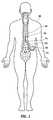
- FIG. 1illustrates a typical spinal cord stimulation system implanted in a patient
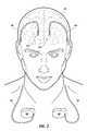
- FIG. 2illustrates a typical deep brain stimulation system implanted in a patient
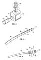
- FIG. 3is an isometric view of the distal end of the lead shown in FIG. 2 ;
- FIG. 4is an isometric view of the distal end of the extension shown in FIG. 2 ;
- FIG. 5is an isometric view of an example of a connector screw block suitable for connecting the lead of FIG. 3 to the extension shown in FIG. 4 ;
- FIG. 6is a top view of the lead shown in FIG. 2 ;
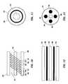
- FIGS. 7 and 8are cross-sectional views taken along lines 7 - 7 and 8 - 8 , respectively, in FIG. 6 ;
- FIG. 9is a top view of an alternate lead configuration
- FIGS. 10 and 11are longitudinal and radial cross-sectional views of a helically wound lead of the type shown in FIG. 6 ;
- FIGS. 12 and 13are longitudinal and radial cross-sectional views, respectively, of a cabled lead
- FIG. 14is an exploded view of a neurostimulation system
- FIG. 15is a cross-sectional view of the extension shown in FIG. 14 taken along line 15 - 15 ;
- FIGS. 16 , 17 , and 18are front, end, and isometric views, respectively, of an electrode in accordance with the present invention.
- FIG. 19is a side view of the distal end of a stimulation lead incorporating the electrode shown in FIGS. 16 , 17 , and 18 ;
- FIG. 20is a side view of a further embodiment of an electrode in accordance with the present invention.
- FIG. 21is a side view of a stimulation lead utilizing a floating electrode in accordance with the present invention.
- FIG. 22is a cross-sectional view illustrating a rolled capacitor
- FIG. 23is a side view of the distal end of a stimulation lead in accordance with an embodiment of the present invention.
- FIG. 24is a cross-sectional view of a further embodiment of a rolled capacitor
- FIG. 25is a cross-sectional view of a discoital capacitor for use in conjunction with the present invention.
- FIG. 26is an isometric view of yet another embodiment of the present invention.
- FIG. 1illustrates a typical SCS system implanted in a patient.
- the systemcomprises a pulse generator such as an SCS neurostimulator 20 , a lead extension 22 having a proximal end coupled to neurostimulator 20 as will be more fully described below, and a lead 24 having proximal end coupled to the distal end of extension 22 and having a distal end coupled to one or more electrodes 26 .
- Neurostimulator 20is typically placed in the abdomen of a patient 28 , and lead 24 is placed somewhere along spinal cord 30 .
- neurostimulator 20may have one or two leads each having four to eight electrodes.
- Such a systemmay also include a physician programmer and a patient programmer (not shown).
- Neurostimulator 20may be considered to be an implantable pulse generator of the type available from Medtronic, Inc. and capable of generating multiple pulses occurring either simultaneously or one pulse shifting in time with respect to the other, and having independently varying amplitudes and pulse widths.
- Neurostimulator 20contains a power source and the electronics for sending precise, electrical pulses to the spinal cord to provide the desired treatment therapy. While neurostimulator 20 typically provides electrical stimulation by way of pulses, other forms of stimulation may be used as continuous electrical stimulation.
- Lead 24is a small medical wire having special insulation thereon and includes one or more insulated electrical conductors each coupled at their proximal end to a connector and to contacts/electrodes 26 at its distal end. Some leads are designed to be inserted into a patient percutaneously (e.g. the Model 3487A Pisces—Quad® lead available from Medtronic, Inc.), and some are designed to be surgically implanted (e.g. Model 3998 Specify® lead, also available form Medtronic, Inc.). Lead 24 may contain a paddle at its distant end for housing electrodes 26 ; e.g. a Medtronic paddle having model number 3587A. Alternatively, electrodes 26 may comprise one or more ring contacts at the distal end of lead 24 as will be more fully described below.
- Electrodes 26may comprise one or more ring contacts at the distal end of lead 24 as will be more fully described below.
- lead 24is shown as being implanted in position to stimulate a specific site in spinal cord 30 , it could also be positioned along the peripheral nerve or adjacent neural tissue ganglia or may be positioned to stimulate muscle tissue. Furthermore, electrodes 26 may be epidural, intrathecal or placed into spinal cord 30 itself. Effective spinal cord stimulation may be achieved by any of these lead placements. While the lead connector at proximal end of lead 24 may be coupled directly to neurostimulator 20 , the lead connector is typically coupled to lead extension 22 as is shown in FIG. 1 . An example of a lead extension is Model 7495 available from Medtronic, Inc.
- a physician's programmerutilizes telemetry to communicate with the implanted neurostimulator 20 to enable the physician to program and manage a patient's therapy and troubleshoot the system.
- a typical physician's programmeris available from Medtronic, Inc. and bears Model No. 7432.
- a patient's programmeralso uses telemetry to communicate with neurostimulator 20 so as to enable the patient to manage some aspects of their own therapy as defined by the physician.
- An example of a patient programmeris Model 7434® 3 EZ Patient Programmer available from Medtronic, Inc.
- Implantation of a neurostimulatortypically begins with the implantation of at least one stimulation lead usually while the patient is under a local anesthetic. While there are many spinal cord lead designs utilized with a number of different implantation techniques, the largest distinction between leads revolves around how they are implanted. For example, surgical leads have been shown to be highly effective, but require a laminectomy for implantation. Percutaneous leads can be introduced through a needle, a much easier procedure. To simplify the following explanation, discussion will focus on percutaneous lead designs, although it will be understood by those skilled in the art that the inventive aspects are equally applicable to surgical leads.
- the lead's distal endis typically anchored to minimize movement of the lead after implantation.
- the lead's proximal endis typically configured to connect to a lead extension 22 . The proximal end of the lead extension is then connected to the neurostimulator 20 .
- FIG. 2illustrates a DBS system implanted in a patient 40 and comprises substantially the same components as does an SCS; that is, at least one neurostimulator, at least one extension, and at least one stimulation lead containing one or more electrodes.
- each neurostimulator 42is implanted in the pectoral region of the patient.
- Extensions 44are deployed up through the patient's neck, and leads 46 are implanted in the patient's brain is as shown at 48 .
- each of the leads 46is connected to its respective extension 44 just above the ear on both sides of patient 40 .
- FIG. 3is an isometric view of the distal end of lead 46 .
- four ring electrodes 48are positioned on the distal end of lead 46 and coupled to internal conductors of filers (not shown) contained within lead 46 .
- FIG. 4is an isometric view of the distal end of extension 44 , which includes a connector portion 45 having four internal contacts 47 .
- the proximal end of the DBS leadis shown in FIG. 3 , plugs into the distal connector 45 of extension 44 , and is held in place by means of, for example, a plurality (e.g. 4) of set screws 50 .
- lead 46terminates in a series of proximal electrical ring contacts 48 (only one of which is shown in FIG. 5 ).
- Lead 46may be inserted through an axially aligned series of openings 52 (again only one shown) in screw block 54 . With a lead 46 so inserted, a series of set screws (only one shown) are screwed into block 54 to drive contacts 48 against blocks 54 and secure and electrically couple the lead 46 . It should be appreciated, however, that other suitable methods for securing lead 46 to extension 44 may be employed.
- the proximal portion of extension 44is secured to neurostimulator 42 as is shown in FIGS. 1 and 2 .
- FIG. 6is a top view of lead 46 shown in FIG. 2 .
- FIGS. 7 and 8are cross-sectional views taken along lines 7 - 7 and 8 - 8 , respectively, in FIG. 6 .
- Distal end 60 of lead 46includes at least one electrode 62 (four are shown). As stated previously, up to eight electrodes may be utilized.
- Each of electrodes 62is preferably constructed as is shown in FIG. 8 . That is, electrode 62 may comprise a conductive ring 71 on the outer surface of the elongate tubing making up distal shaft 60 .
- Each electrode 62is electrically coupled to a longitudinal wire 66 (shown in FIGS. 7 and 8 ) each of which extends to a contact 64 at the proximal end of lead 46 .
- Longitudinal wires 66may be of a variety of configurations; e.g. discreet wires, printed circuit conductors, etc. From the arrangement shown in FIG. 6 , it should be clear that four conductors or filers run through the body of lead 46 to electrically connect the proximal electrodes 64 to the distal electrodes 62 . As will be further discussed below, the longitudinal conductors 66 may be spirally configured along the axis of lead 46 until they reach the connector contacts.
- the shaft of lead 46preferably has a lumen 68 extending therethrough for receiving a stylet that adds a measure of rigidity during installation of the lead.
- the shaftpreferably comprises a comparatively stiffer inner tubing member 70 (e.g. a polyamine, polyamide, high density polyethylene, polypropylene, polycarbonate or the like). Polyamide polymers are preferred.
- the shaftpreferably includes a comparatively softer outer tubing member 72 ; e.g. silicon or other suitable elastomeric polymer.
- Conductive rings 71are preferably of a biocompatible metal such as one selected from the noble group of metals, preferably palladium, platinum or gold and their alloys.
- FIG. 9illustrates an alternative lead 74 wherein distal end 76 is broader (e.g. paddle-shaped) to support a plurality of distal electrodes 78 .
- a lead of this typeis shown in FIG. 1 .
- distal electrodes 78are coupled to contacts 64 each respectively by means of an internal conductor or filer.
- a more detailed description of the leads shown in FIGS. 6 and 9may be found in U.S. Pat. No. 6,529,774 issued Mar. 4, 2003 and entitled “Extradural Leads, Neurostimulator Assemblies, and Processes of Using Them for Somatosensory and Brain Stimulation”.
- FIGS. 10 and 11are longitudinal and radial cross-sectional views, respectively, of a helically wound lead of the type shown in FIG. 6 .
- the leadcomprises an outer lead body 80 ; a plurality of helically wound, co-radial lead filers 82 ; and a stylet lumen 84 .
- a styletis a stiff, formable insert placed in the lead during implant so as to enable the physician to steer the lead to an appropriate location.
- FIG. 10illustrates four separate, co-radially wound filers 86 , 88 , 90 , and 92 which are electrically insulated from each other and electrically couple a single electrode 62 ( FIG. 6 ) to a single contact 64 ( FIG. 6 ).
- lead filers 82have a specific pitch and form a helix of a specific diameter.
- the helix diameteris relevant in determining the inductance of the lead.
- These filersthemselves also have a specific diameter and are made of a specific material.
- the filer diameter, material, pitch and helix diameterare relevant in determining the impedance of the lead.
- the inductancecontributes to a frequency dependent impedance.
- FIGS. 12 and 13are longitudinal and radially cross-sectional views, respectively, of a cabled lead.
- the leadcomprises outer lead body 94 , stylet lumen 96 , and a plurality (e.g. four to eight) of straight lead filers 98 .
- each straight filer 98may, if desired, be of a cable construction comprised of a plurality of insulated straight filers; e.g. a center filer surrounded by an additional six filers.
- FIG. 14is an exploded view of a neurostimulation system that includes an extension 100 configured to be coupled between a neurostimulator 102 and lead 104 .
- the proximal portion of extension 100comprises a connector 106 configured to be received or plugged into connector block 108 of neurostimulator 102 .
- the distal end of extension 100likewise comprises a connector 110 including internal contacts 111 and is configured to receive the proximal end of lead 104 having contacts 112 thereon.
- the distal end of lead 104includes distal electrodes 114 .
- FIG. 15is a cross-sectional view of extension 100 .
- Lead extension 100has a typical diameter of 0.1 inch, which is significantly larger than that of lead 104 so as to make extension 100 more durable than lead 104 .
- Extension 100differs from lead 104 also in that each filer 106 in the lead body is helically wound or coiled in its own lumen 108 and not co-radially wound with the rest of the filers as was the case in lead 104 .
- the diameter of typical percutaneous leadsis approximately 0.05 inch. This diameter is based upon the diameter of the needle utilized in the surgical procedure to deploy the lead and upon other clinical anatomical requirements.
- the length of such percutaneous SCS leadsis based upon other clinical anatomical requirements and is typically 28 centimeters; however, other lengths are utilized to meet particular needs of specific patients and to accommodate special implant locations.
- Lead lengthis an important factor in determining the suitability of using the lead in an MRI environment. For example, the greater length of the lead, the larger the effective loop area that is impacted by the electromagnetic field (e.g. the longer the lead, the larger the antenna). Furthermore, depending on the lead length, there can be standing wave effects that create areas of high current along the lead body. This can be problematic if the areas of high current are near the distal electrodes.
- the cable leadhas smaller DC resistance because the length of the straight filer is less than that of a coiled filer and the impedance at frequency is reduced because the inductance has been significantly reduced. It has been determined that the newer cabled filer designs tend to be more problematic in an MRI environment than do the wound helix filer designs. It should be noted that straight filers for cable leads sometimes comprise braided stranded wire that includes a number of smaller strands woven to make up each filer. This being the case, the number of strands could be varied to alter the impedance.
- the electromagnetic fields within an MRI environmentproduce RF currents in the leads that can result in undesirable temperature increases at the leads stimulation electrodes. It has been discovered that this temperature increase can be reduced by providing stimulation electrodes having effective surface areas that increase in an MRI environment.
- FIGS. 16 , 17 , and 18are front, end, and isometric views of a stimulation electrode 110 for use in an MRI-safe stimulation lead.
- the stimulation electrodecomprises a first ring portion 112 having a predetermined outer diameter substantially equal to the outer diameter of lead body 104 ( FIG. 19 ).
- a second ring portion 116extends from portion 112 and has an outer diameter smaller than that of the first ring portion. Opening 118 extends through both ring portions to permit conductive filers (not shown) to pass there through.
- FIG. 19is a side view of the distal end of a stimulation lead 104 that has positioned thereon four electrodes 110 of the type previously described in connection with FIGS. 16 , 17 , and 18 .
- lead 104includes a lead body 120 having an outer diameter substantially equal to that of the first ring portion 112 , and these first ring portions serve as the stimulation electrodes 114 in FIG. 14 .
- second ring portions 116have a smaller outer diameter, they are covered by lead body 120 ; i.e. the surface of the second ring portions 116 is covered by a layer of the dielectric lead body material. Thus, the second ring portions are shown in dotted line format in FIG. 19 .
- the electrodemay be manufactured with a dielectric layer over the outer surface of the second ring portion.
- the outer diameter of the dielectric layerwould have an outer diameter substantially equal to the outer diameter of lead body 120 .
- the stimulation electrodesDuring an MRI scan, energy is created in the stimulation lead, and some of that energy exits the lead through the stimulation electrodes in the form of current. This current in the stimulation electrodes can cause the temperature of the electrodes to increase to an undesirable level. By increasing the surface area of the stimulation electrodes, the current density in the stimulation electrodes is decreased thereby decreasing the temperature of the electrodes.
- the stimulation electrodeBy utilizing the second ring portion 116 , the stimulation electrode has been effectively extended to be longer than just the stimulation portion of the electrode. The extended portion has a smaller diameter and is covered by a thin layer of dielectric material as above described.
- the second ring portion 116 and the dielectric material thereonform a capacitor with body tissue and/or fluids. The resulting capacitor becomes conductive at MRI frequencies.
- the stimulation electrodeshave an effective surface area larger than the surface area of their respective first ring portions 112 and the resulting lower density current may be safely dissipated into body tissue or fluid.
- the material used to cover the second ring portion 116may be any type of a biocompatible, non-conductive polymer; preferably a silicone or Teflon type of polymer as these are widely used as lead jackets.
- the thickness of the layeri.e. the difference between the outer radii of the first and second ring portions
- second ring portion 116can be flexible and therefore not significantly increase the stiffness of the distal end of the lead.
- second portion 116may be in the form of a coil as shown in FIG. 20 .
- second portion 116may be configured as a braid, fenestrated tube, or bellows.
- heat generated at MRI frequenciescan be dissipated by means of a shunt and a floating electrode.
- FIG. 21which is similar to the lead shown in FIG. 14 where like elements are denoted by line reference numerals. That is, lead 104 has a plurality of proximal contacts 112 and a plurality of stimulation electrodes 114 .
- the lead shown in FIG. 21also comprises a floating electrode 124 that is placed somewhere along the length of lead 104 , preferably proximate the stimulation electrodes 114 .
- Floating electrode 124is not used for stimulation but is configured to be capacitively coupled to the stimulation electrodes 114 so as to increase the effective surface area of the electrodes in the high frequency environment of an MRI scan. It should be noted that, if desired, floating electrode 124 may have a layer of dielectric material disposed thereon and thereby be capacitively coupled to the patient's body.
- capacitive coupling between floating electrode 124 and stimulation electrodes 114may be accomplished by configuring a capacitor within each stimulation electrode 114 (i.e. an electrode capacitor) and then electrically coupling the electrode capacitor to floating electrode 124 .
- a capacitor within each stimulation electrode 114i.e. an electrode capacitor
- Thismay be accomplished using a rolled capacitor construction 126 shown in cross-section in FIG. 22 wherein the outer capacitor roll or plate 128 comprises the stimulation electrode and an inner roll or plate 130 comprises in inner capacitor plate.
- the space between the outer roll 128 and inner roll 130may comprise a dielectric material 129 to complete the capacitor. It is then only necessary to electrically couple each of the electrode capacitors to floating electrode 124 . This may be accomplished by means of a wire 132 coupled to each electrode capacitor (i.e.
- inner roll or plate 132may comprise multiple coils or turns 131 as shown in FIG. 24 .
- the space between coils and platescomprises dielectric material 129 .
- a ceramic capacitore.g. a discoital capacitor
- a capacitoris comprised of inner and outer plates 134 and 136 separated by a ceramic material 138 . This capacitor is then positioned within stimulation electrode 114 such that plate 134 is electrically coupled to electrode 114 .
- Each of the electrode/capacitor assemblies thus formedmay be electrically coupled together and to floating electrode 124 by, for example, a single wire 132 as shown in FIG. 23 .
- Discoital capacitorsare well known and further discussion is not deemed necessary; however, the interested reader is referred to U.S. Pat. No. 6,660,116 issued Dec. 9, 2003 and entitled “Capacitive Filtered Feedthrough Array for an Implantable Medical Device”.
- FIG. 26illustrates yet another embodiment of the present invention.
- Floating contact 124is provided with a conductive extension 140 that extends through stimulation electrodes 114 in capacitor forming relationship therewith.
- the area between each stimulation electrode 114 and extension 140is occupied by a dielectric material.
- the capacitors formed by stimulation electrodes 114 and extension 140will conduct induced current to floating electrode 124 via extension 140 . This current is then dissipated into a patient's body tissue or fluid at a low current density, thus reducing unwanted heating of the stimulation electrodes 114 .
Landscapes
- Health & Medical Sciences (AREA)
- Neurology (AREA)
- Neurosurgery (AREA)
- General Health & Medical Sciences (AREA)
- Life Sciences & Earth Sciences (AREA)
- Veterinary Medicine (AREA)
- Engineering & Computer Science (AREA)
- Biomedical Technology (AREA)
- Nuclear Medicine, Radiotherapy & Molecular Imaging (AREA)
- Radiology & Medical Imaging (AREA)
- Public Health (AREA)
- Animal Behavior & Ethology (AREA)
- Heart & Thoracic Surgery (AREA)
- Cardiology (AREA)
- Psychology (AREA)
- Orthopedic Medicine & Surgery (AREA)
- Electrotherapy Devices (AREA)
Abstract
Description
Claims (18)
Priority Applications (7)
| Application Number | Priority Date | Filing Date | Title |
|---|---|---|---|
| US11/117,882US7853332B2 (en) | 2005-04-29 | 2005-04-29 | Lead electrode for use in an MRI-safe implantable medical device |
| EP06721067.4AEP1874396B1 (en) | 2005-04-29 | 2006-02-23 | Lead electrode for use in an mri-safe implantable medical device |
| PCT/US2006/006754WO2006118640A1 (en) | 2005-04-29 | 2006-02-23 | Lead electrode for use in an mri-safe implantable medical device |
| US12/954,585US8849417B2 (en) | 2005-04-29 | 2010-11-24 | Lead electrode for use in an MRI-safe implantable medical device |
| US14/500,298US9517341B2 (en) | 2005-04-29 | 2014-09-29 | Lead electrode for use in an MRI-safe implantable medical device |
| US15/376,615US10004897B2 (en) | 2005-04-29 | 2016-12-12 | Lead electrode for use in an MRI-safe implantable medical device |
| US16/007,117US10426954B2 (en) | 2005-04-29 | 2018-06-13 | Lead electrode for use in an MRI-safe implantable medical device |
Applications Claiming Priority (1)
| Application Number | Priority Date | Filing Date | Title |
|---|---|---|---|
| US11/117,882US7853332B2 (en) | 2005-04-29 | 2005-04-29 | Lead electrode for use in an MRI-safe implantable medical device |
Related Child Applications (1)
| Application Number | Title | Priority Date | Filing Date |
|---|---|---|---|
| US12/954,585ContinuationUS8849417B2 (en) | 2005-04-29 | 2010-11-24 | Lead electrode for use in an MRI-safe implantable medical device |
Publications (2)
| Publication Number | Publication Date |
|---|---|
| US20060247747A1 US20060247747A1 (en) | 2006-11-02 |
| US7853332B2true US7853332B2 (en) | 2010-12-14 |
Family
ID=36645335
Family Applications (5)
| Application Number | Title | Priority Date | Filing Date |
|---|---|---|---|
| US11/117,882Active2027-05-05US7853332B2 (en) | 2005-04-29 | 2005-04-29 | Lead electrode for use in an MRI-safe implantable medical device |
| US12/954,585Active2028-01-04US8849417B2 (en) | 2005-04-29 | 2010-11-24 | Lead electrode for use in an MRI-safe implantable medical device |
| US14/500,298Expired - Fee RelatedUS9517341B2 (en) | 2005-04-29 | 2014-09-29 | Lead electrode for use in an MRI-safe implantable medical device |
| US15/376,615Expired - LifetimeUS10004897B2 (en) | 2005-04-29 | 2016-12-12 | Lead electrode for use in an MRI-safe implantable medical device |
| US16/007,117Expired - LifetimeUS10426954B2 (en) | 2005-04-29 | 2018-06-13 | Lead electrode for use in an MRI-safe implantable medical device |
Family Applications After (4)
| Application Number | Title | Priority Date | Filing Date |
|---|---|---|---|
| US12/954,585Active2028-01-04US8849417B2 (en) | 2005-04-29 | 2010-11-24 | Lead electrode for use in an MRI-safe implantable medical device |
| US14/500,298Expired - Fee RelatedUS9517341B2 (en) | 2005-04-29 | 2014-09-29 | Lead electrode for use in an MRI-safe implantable medical device |
| US15/376,615Expired - LifetimeUS10004897B2 (en) | 2005-04-29 | 2016-12-12 | Lead electrode for use in an MRI-safe implantable medical device |
| US16/007,117Expired - LifetimeUS10426954B2 (en) | 2005-04-29 | 2018-06-13 | Lead electrode for use in an MRI-safe implantable medical device |
Country Status (3)
| Country | Link |
|---|---|
| US (5) | US7853332B2 (en) |
| EP (1) | EP1874396B1 (en) |
| WO (1) | WO2006118640A1 (en) |
Cited By (51)
| Publication number | Priority date | Publication date | Assignee | Title |
|---|---|---|---|---|
| US20110196448A1 (en)* | 2007-01-18 | 2011-08-11 | Medtronic, Inc. | Bi-directional connector assembly for an implantable medical device |
| US8027736B2 (en)* | 2005-04-29 | 2011-09-27 | Medtronic, Inc. | Lead electrode for use in an MRI-safe implantable medical device |
| US8369930B2 (en) | 2009-06-16 | 2013-02-05 | MRI Interventions, Inc. | MRI-guided devices and MRI-guided interventional systems that can track and generate dynamic visualizations of the devices in near real time |
| US8868208B2 (en) | 2012-10-23 | 2014-10-21 | Medtronic, Inc. | MR-compatible implantable medical lead |
| US8954168B2 (en) | 2012-06-01 | 2015-02-10 | Cardiac Pacemakers, Inc. | Implantable device lead including a distal electrode assembly with a coiled component |
| US8958889B2 (en) | 2012-08-31 | 2015-02-17 | Cardiac Pacemakers, Inc. | MRI compatible lead coil |
| US8983623B2 (en) | 2012-10-18 | 2015-03-17 | Cardiac Pacemakers, Inc. | Inductive element for providing MRI compatibility in an implantable medical device lead |
| US9050457B2 (en) | 2009-12-31 | 2015-06-09 | Cardiac Pacemakers, Inc. | MRI conditionally safe lead with low-profile conductor for longitudinal expansion |
| US9084883B2 (en) | 2009-03-12 | 2015-07-21 | Cardiac Pacemakers, Inc. | Thin profile conductor assembly for medical device leads |
| US9186499B2 (en) | 2009-04-30 | 2015-11-17 | Medtronic, Inc. | Grounding of a shield within an implantable medical lead |
| US9199077B2 (en) | 2009-12-31 | 2015-12-01 | Cardiac Pacemakers, Inc. | MRI conditionally safe lead with multi-layer conductor |
| US9254380B2 (en) | 2009-10-19 | 2016-02-09 | Cardiac Pacemakers, Inc. | MRI compatible tachycardia lead |
| US9259572B2 (en) | 2007-04-25 | 2016-02-16 | Medtronic, Inc. | Lead or lead extension having a conductive body and conductive body contact |
| US9259290B2 (en) | 2009-06-08 | 2016-02-16 | MRI Interventions, Inc. | MRI-guided surgical systems with proximity alerts |
| US9302101B2 (en) | 2004-03-30 | 2016-04-05 | Medtronic, Inc. | MRI-safe implantable lead |
| US9463317B2 (en) | 2012-04-19 | 2016-10-11 | Medtronic, Inc. | Paired medical lead bodies with braided conductive shields having different physical parameter values |
| US9504821B2 (en) | 2014-02-26 | 2016-11-29 | Cardiac Pacemakers, Inc. | Construction of an MRI-safe tachycardia lead |
| US9517341B2 (en) | 2005-04-29 | 2016-12-13 | Medtronic, Inc. | Lead electrode for use in an MRI-safe implantable medical device |
| US20170135709A1 (en)* | 2015-11-18 | 2017-05-18 | Shockwave Medical, Inc. | Shock wave electrodes |
| US9731119B2 (en) | 2008-03-12 | 2017-08-15 | Medtronic, Inc. | System and method for implantable medical device lead shielding |
| US9750944B2 (en) | 2009-12-30 | 2017-09-05 | Cardiac Pacemakers, Inc. | MRI-conditionally safe medical device lead |
| US9802037B2 (en) | 2015-03-05 | 2017-10-31 | Bradley D. Vilims | Tension loop for a spinal cord stimulator |
| US9808613B2 (en) | 2012-08-24 | 2017-11-07 | Boston Scientific Neuromodulation Corporation | Systems and methods for improving RF compatibility of electrical stimulation leads |
| US9993638B2 (en) | 2013-12-14 | 2018-06-12 | Medtronic, Inc. | Devices, systems and methods to reduce coupling of a shield and a conductor within an implantable medical lead |
| US10155111B2 (en) | 2014-07-24 | 2018-12-18 | Medtronic, Inc. | Methods of shielding implantable medical leads and implantable medical lead extensions |
| US10279171B2 (en) | 2014-07-23 | 2019-05-07 | Medtronic, Inc. | Methods of shielding implantable medical leads and implantable medical lead extensions |
| US10398893B2 (en) | 2007-02-14 | 2019-09-03 | Medtronic, Inc. | Discontinuous conductive filler polymer-matrix composites for electromagnetic shielding |
| US10478618B2 (en) | 2015-03-05 | 2019-11-19 | Bradley D. Vilims | Adjustable length tension sleeve for electrical or thermal stimulation device |
| US10682178B2 (en) | 2012-06-27 | 2020-06-16 | Shockwave Medical, Inc. | Shock wave balloon catheter with multiple shock wave sources |
| US11076874B2 (en) | 2012-08-06 | 2021-08-03 | Shockwave Medical, Inc. | Low profile electrodes for an angioplasty shock wave catheter |
| US11478261B2 (en) | 2019-09-24 | 2022-10-25 | Shockwave Medical, Inc. | System for treating thrombus in body lumens |
| US11622780B2 (en) | 2017-11-17 | 2023-04-11 | Shockwave Medical, Inc. | Low profile electrodes for a shock wave catheter |
| US11672976B2 (en) | 2019-10-10 | 2023-06-13 | Saluda Medical Pty Limited | Lead for an active implantable medical device with decoy |
| US11992232B2 (en) | 2020-10-27 | 2024-05-28 | Shockwave Medical, Inc. | System for treating thrombus in body lumens |
| US12023098B2 (en) | 2021-10-05 | 2024-07-02 | Shockwave Medical, Inc. | Lesion crossing shock wave catheter |
| US12035932B1 (en) | 2023-04-21 | 2024-07-16 | Shockwave Medical, Inc. | Intravascular lithotripsy catheter with slotted emitter bands |
| US12096950B2 (en) | 2012-09-13 | 2024-09-24 | Shockwave Medical, Inc. | Shockwave catheter system with energy control |
| US12102342B2 (en) | 2008-11-05 | 2024-10-01 | Shockwave Medical, Inc. | Shockwave valvuloplasty catheter system |
| US12114874B2 (en) | 2018-06-21 | 2024-10-15 | Shockwave Medical, Inc. | System for treating occlusions in body lumens |
| US12144516B2 (en) | 2016-10-06 | 2024-11-19 | Shockwave Medical, Inc. | Aortic leaflet repair using shock wave applicators |
| US12178458B1 (en) | 2024-05-16 | 2024-12-31 | Shockwave Medical, Inc. | Guidewireless shock wave catheters |
| US12193691B2 (en) | 2012-09-13 | 2025-01-14 | Shockwave Medical, Inc. | Shock wave catheter system with energy control |
| US12220141B2 (en) | 2023-06-29 | 2025-02-11 | Shockwave Medical, Inc. | Catheter system with independently controllable bubble and arc generation |
| US12232754B2 (en) | 2017-06-19 | 2025-02-25 | Shockwave Medical, Inc. | Device and method for generating forward directed shock waves |
| US12274460B2 (en) | 2019-09-24 | 2025-04-15 | Shockwave Medical, Inc. | Lesion crossing shock wave catheter |
| US12290268B2 (en) | 2023-03-31 | 2025-05-06 | Shockwave Medical, Inc. | Shockwave catheters for treating rhinosinusitis |
| US12310605B2 (en) | 2012-08-08 | 2025-05-27 | Shockwave Medical, Inc. | Shock wave valvuloplasty with multiple balloons |
| US12402899B2 (en) | 2023-11-30 | 2025-09-02 | Shockwave Medical, Inc. | Systems, devices, and methods for generating shock waves in a forward direction |
| US12426938B2 (en) | 2019-09-24 | 2025-09-30 | Shockwave Medical, Inc. | Low profile electrodes for a shock wave catheter |
| US12426904B2 (en) | 2023-11-17 | 2025-09-30 | Shockwave Medical, Inc. | Intravascular lithotripsy catheter with oscillating impactor |
| US12433620B2 (en) | 2024-02-23 | 2025-10-07 | Shockwave Medical, Inc. | Locus emitter shock wave catheter devices with increased longevity and higher sonic output |
Families Citing this family (90)
| Publication number | Priority date | Publication date | Assignee | Title |
|---|---|---|---|---|
| US8244370B2 (en)* | 2001-04-13 | 2012-08-14 | Greatbatch Ltd. | Band stop filter employing a capacitor and an inductor tank circuit to enhance MRI compatibility of active medical devices |
| US20050288753A1 (en)* | 2003-08-25 | 2005-12-29 | Biophan Technologies, Inc. | Medical device with an electrically conductive anti-antenna member |
| US20050288750A1 (en)* | 2003-08-25 | 2005-12-29 | Biophan Technologies, Inc. | Medical device with an electrically conductive anti-antenna member |
| US6949929B2 (en)* | 2003-06-24 | 2005-09-27 | Biophan Technologies, Inc. | Magnetic resonance imaging interference immune device |
| US20050283214A1 (en)* | 2003-08-25 | 2005-12-22 | Biophan Technologies, Inc. | Medical device with an electrically conductive anti-antenna member |
| US20050283167A1 (en)* | 2003-08-25 | 2005-12-22 | Biophan Technologies, Inc. | Medical device with an electrically conductive anti-antenna member |
| US9295828B2 (en) | 2001-04-13 | 2016-03-29 | Greatbatch Ltd. | Self-resonant inductor wound portion of an implantable lead for enhanced MRI compatibility of active implantable medical devices |
| WO2002083016A1 (en) | 2001-04-13 | 2002-10-24 | Surgi-Vision, Inc. | Systems and methods for magnetic-resonance-guided interventional procedures |
| US7388378B2 (en)* | 2003-06-24 | 2008-06-17 | Medtronic, Inc. | Magnetic resonance imaging interference immune device |
| US20050288755A1 (en)* | 2003-08-25 | 2005-12-29 | Biophan Technologies, Inc. | Medical device with an electrically conductive anti-antenna member |
| US20050288756A1 (en)* | 2003-08-25 | 2005-12-29 | Biophan Technologies, Inc. | Medical device with an electrically conductive anti-antenna member |
| US20050288754A1 (en)* | 2003-08-25 | 2005-12-29 | Biophan Technologies, Inc. | Medical device with an electrically conductive anti-antenna member |
| US20050283213A1 (en)* | 2003-08-25 | 2005-12-22 | Biophan Technologies, Inc. | Medical device with an electrically conductive anti-antenna member |
| US20050288757A1 (en)* | 2003-08-25 | 2005-12-29 | Biophan Technologies, Inc. | Medical device with an electrically conductive anti-antenna member |
| US8868212B2 (en) | 2003-08-25 | 2014-10-21 | Medtronic, Inc. | Medical device with an electrically conductive anti-antenna member |
| US9155877B2 (en) | 2004-03-30 | 2015-10-13 | Medtronic, Inc. | Lead electrode for use in an MRI-safe implantable medical device |
| US8989840B2 (en) | 2004-03-30 | 2015-03-24 | Medtronic, Inc. | Lead electrode for use in an MRI-safe implantable medical device |
| US7877150B2 (en) | 2004-03-30 | 2011-01-25 | Medtronic, Inc. | Lead electrode for use in an MRI-safe implantable medical device |
| US7844343B2 (en) | 2004-03-30 | 2010-11-30 | Medtronic, Inc. | MRI-safe implantable medical device |
| WO2006023700A2 (en)* | 2004-08-20 | 2006-03-02 | Biophan Technologies, Inc. | Magnetic resonance imaging interference immune device |
| US8014867B2 (en) | 2004-12-17 | 2011-09-06 | Cardiac Pacemakers, Inc. | MRI operation modes for implantable medical devices |
| US8280526B2 (en) | 2005-02-01 | 2012-10-02 | Medtronic, Inc. | Extensible implantable medical lead |
| US20070299490A1 (en)* | 2006-06-23 | 2007-12-27 | Zhongping Yang | Radiofrequency (rf)-shunted sleeve head and use in electrical stimulation leads |
| US9020610B2 (en)* | 2006-06-23 | 2015-04-28 | Medtronic, Inc. | Electrode system with shunt electrode |
| US7734354B1 (en) | 2006-08-04 | 2010-06-08 | Advanced Neuromodulation Systems, Inc. | Stimulation lead, stimulation system, and method for limiting MRI induced current in a stimulation lead |
| US7610101B2 (en) | 2006-11-30 | 2009-10-27 | Cardiac Pacemakers, Inc. | RF rejecting lead |
| US7962224B1 (en)* | 2007-02-05 | 2011-06-14 | Advanced Neuromodulation Systems, Inc. | Stimulation lead, stimulation system, and method for limiting MRI-induced current in a stimulation lead |
| US10537730B2 (en) | 2007-02-14 | 2020-01-21 | Medtronic, Inc. | Continuous conductive materials for electromagnetic shielding |
| WO2008117383A1 (en)* | 2007-03-23 | 2008-10-02 | Fujitsu Limited | Electronic device, electronic apparatus mounting electronic device, article mounting electronic device, and method for manufacturing electronic device |
| US8103347B2 (en) | 2007-04-25 | 2012-01-24 | Advanced Neuromodulation Systems, Inc. | Implantable pulse generator comprising MRI current limiting windings in header structure |
| EP2198317A2 (en)* | 2007-09-24 | 2010-06-23 | Boston Scientific Limited | Mri phase visualization of interventional devices |
| US8032230B1 (en) | 2007-10-09 | 2011-10-04 | Advanced Neuromodulation Systems, Inc. | Stimulation lead, stimulation system, and method for limiting MRI induced current in a stimulation lead |
| US8275464B2 (en) | 2007-12-06 | 2012-09-25 | Cardiac Pacemakers, Inc. | Leads with high surface resistance |
| US8032228B2 (en) | 2007-12-06 | 2011-10-04 | Cardiac Pacemakers, Inc. | Method and apparatus for disconnecting the tip electrode during MRI |
| US8086321B2 (en) | 2007-12-06 | 2011-12-27 | Cardiac Pacemakers, Inc. | Selectively connecting the tip electrode during therapy for MRI shielding |
| AU2008335462B2 (en)* | 2007-12-06 | 2014-02-20 | Cardiac Pacemakers, Inc. | Implantable lead having a variable coil conductor pitch |
| WO2009076169A2 (en)* | 2007-12-06 | 2009-06-18 | Cardiac Pacemakers, Inc. | Implantable lead with shielding |
| WO2009100003A1 (en) | 2008-02-06 | 2009-08-13 | Cardiac Pacemakers, Inc. | Lead with mri compatible design features |
| US8311637B2 (en)* | 2008-02-11 | 2012-11-13 | Cardiac Pacemakers, Inc. | Magnetic core flux canceling of ferrites in MRI |
| US8255055B2 (en)* | 2008-02-11 | 2012-08-28 | Cardiac Pacemakers, Inc. | MRI shielding in electrodes using AC pacing |
| US8160717B2 (en) | 2008-02-19 | 2012-04-17 | Cardiac Pacemakers, Inc. | Model reference identification and cancellation of magnetically-induced voltages in a gradient magnetic field |
| US10080889B2 (en) | 2009-03-19 | 2018-09-25 | Greatbatch Ltd. | Low inductance and low resistance hermetically sealed filtered feedthrough for an AIMD |
| US9108066B2 (en) | 2008-03-20 | 2015-08-18 | Greatbatch Ltd. | Low impedance oxide resistant grounded capacitor for an AIMD |
| EP2110156B1 (en)* | 2008-04-14 | 2016-11-02 | Biotronik CRM Patent AG | Field decoupling element for use with an implantable lead and implantable medical device |
| WO2009134901A1 (en)* | 2008-04-30 | 2009-11-05 | Medtronic, Inc. | Magnetic resonance imaging shunt electrodes with self-healing coatings |
| US8103360B2 (en)* | 2008-05-09 | 2012-01-24 | Foster Arthur J | Medical lead coil conductor with spacer element |
| US8571661B2 (en) | 2008-10-02 | 2013-10-29 | Cardiac Pacemakers, Inc. | Implantable medical device responsive to MRI induced capture threshold changes |
| US8335570B2 (en)* | 2008-10-09 | 2012-12-18 | Boston Scientific Neuromodulation Corporation | Electrical stimulation leads having RF compatibility and methods of use and manufacture |
| CN102186532A (en)* | 2008-10-15 | 2011-09-14 | 皇家飞利浦电子股份有限公司 | Probe for implantable electro-stimulation device |
| US20100106215A1 (en)* | 2008-10-23 | 2010-04-29 | Stubbs Scott R | Systems and methods to detect implantable medical device configuaration changes affecting mri conditional safety |
| EP2398553B1 (en) | 2009-02-19 | 2015-07-22 | Cardiac Pacemakers, Inc. | Systems for providing arrhythmia therapy in mri environments |
| US8521304B2 (en)* | 2009-06-15 | 2013-08-27 | Pacesetter, Inc. | MRI compatible implantable lead with a distributed band stop filter |
| ES2547713T3 (en) | 2009-06-26 | 2015-10-08 | Cardiac Pacemakers, Inc. | Bypass of a medical device that includes a single-coil coil with improved torque transmission capacity and reduced RM heating |
| US8601672B2 (en)* | 2009-07-31 | 2013-12-10 | Advanced Neuromodulation Systems, Inc. | Method for fabricating a stimulation lead to reduce MRI heating |
| US8538553B2 (en)* | 2009-10-06 | 2013-09-17 | Pacesetter, Inc. | MRI compatible implantable lead |
| US8335572B2 (en) | 2009-10-08 | 2012-12-18 | Cardiac Pacemakers, Inc. | Medical device lead including a flared conductive coil |
| WO2011043898A2 (en)* | 2009-10-09 | 2011-04-14 | Cardiac Pacemakers, Inc. | Mri compatible medical device lead including transmission line notch filters |
| US8554338B2 (en)* | 2009-11-05 | 2013-10-08 | Pacesetter, Inc. | MRI-compatible implantable lead having a heat spreader and method of using same |
| US9014815B2 (en)* | 2009-11-19 | 2015-04-21 | Medtronic, Inc. | Electrode assembly in a medical electrical lead |
| JP5558583B2 (en) | 2009-12-08 | 2014-07-23 | カーディアック ペースメイカーズ, インコーポレイテッド | Implantable medical device including automatic tachycardia detection and control in an MRI environment |
| US20110144722A1 (en)* | 2009-12-10 | 2011-06-16 | Pacesetter, Inc. | Mri-compatible implantable lead with improved lc resonant component |
| US20110152990A1 (en)* | 2009-12-22 | 2011-06-23 | Pacesetter, Inc. | Mri compatible lead employing multiple miniature inductors |
| US8406895B2 (en)* | 2009-12-30 | 2013-03-26 | Cardiac Pacemakers, Inc. | Implantable electrical lead including a cooling assembly to dissipate MRI induced electrode heat |
| US8306630B2 (en)* | 2009-12-30 | 2012-11-06 | Cardiac Pacemakers, Inc. | Apparatus to selectively increase medical device lead inner conductor inductance |
| US9126031B2 (en) | 2010-04-30 | 2015-09-08 | Medtronic, Inc. | Medical electrical lead with conductive sleeve head |
| US8825181B2 (en) | 2010-08-30 | 2014-09-02 | Cardiac Pacemakers, Inc. | Lead conductor with pitch and torque control for MRI conditionally safe use |
| US8965482B2 (en) | 2010-09-30 | 2015-02-24 | Nevro Corporation | Systems and methods for positioning implanted devices in a patient |
| US8805519B2 (en) | 2010-09-30 | 2014-08-12 | Nevro Corporation | Systems and methods for detecting intrathecal penetration |
| US8630718B2 (en) | 2010-11-18 | 2014-01-14 | Cardiac Pacemakers, Inc. | Insulative structure for MRI compatible leads |
| US11198014B2 (en) | 2011-03-01 | 2021-12-14 | Greatbatch Ltd. | Hermetically sealed filtered feedthrough assembly having a capacitor with an oxide resistant electrical connection to an active implantable medical device housing |
| US10596369B2 (en) | 2011-03-01 | 2020-03-24 | Greatbatch Ltd. | Low equivalent series resistance RF filter for an active implantable medical device |
| US10272252B2 (en) | 2016-11-08 | 2019-04-30 | Greatbatch Ltd. | Hermetic terminal for an AIMD having a composite brazed conductive lead |
| US10350421B2 (en) | 2013-06-30 | 2019-07-16 | Greatbatch Ltd. | Metallurgically bonded gold pocket pad for grounding an EMI filter to a hermetic terminal for an active implantable medical device |
| US9427596B2 (en) | 2013-01-16 | 2016-08-30 | Greatbatch Ltd. | Low impedance oxide resistant grounded capacitor for an AIMD |
| US9931514B2 (en) | 2013-06-30 | 2018-04-03 | Greatbatch Ltd. | Low impedance oxide resistant grounded capacitor for an AIMD |
| US8666512B2 (en) | 2011-11-04 | 2014-03-04 | Cardiac Pacemakers, Inc. | Implantable medical device lead including inner coil reverse-wound relative to shocking coil |
| AU2013211937B2 (en) | 2012-01-25 | 2016-07-28 | Nevro Corporation | Lead anchors and associated systems and methods |
| AU2013249088B2 (en) | 2012-04-20 | 2015-12-03 | Cardiac Pacemakers, Inc. | Implantable medical device lead including a unifilar coiled cable |
| USRE46699E1 (en) | 2013-01-16 | 2018-02-06 | Greatbatch Ltd. | Low impedance oxide resistant grounded capacitor for an AIMD |
| US9265935B2 (en) | 2013-06-28 | 2016-02-23 | Nevro Corporation | Neurological stimulation lead anchors and associated systems and methods |
| WO2015123249A1 (en) | 2014-02-11 | 2015-08-20 | Cardiac Pacemakers, Inc | Rf shield for an implantable lead |
| US10798205B2 (en)* | 2016-04-13 | 2020-10-06 | Facebook, Inc. | Cache system for live broadcast streaming |
| EP3454935B1 (en) | 2016-05-11 | 2024-07-24 | Inspire Medical Systems, Inc. | Attenuation arrangement for implantable medical device |
| US10249415B2 (en) | 2017-01-06 | 2019-04-02 | Greatbatch Ltd. | Process for manufacturing a leadless feedthrough for an active implantable medical device |
| US10980999B2 (en) | 2017-03-09 | 2021-04-20 | Nevro Corp. | Paddle leads and delivery tools, and associated systems and methods |
| US10912945B2 (en) | 2018-03-22 | 2021-02-09 | Greatbatch Ltd. | Hermetic terminal for an active implantable medical device having a feedthrough capacitor partially overhanging a ferrule for high effective capacitance area |
| US10905888B2 (en) | 2018-03-22 | 2021-02-02 | Greatbatch Ltd. | Electrical connection for an AIMD EMI filter utilizing an anisotropic conductive layer |
| WO2019191423A1 (en) | 2018-03-29 | 2019-10-03 | Nevro Corp. | Leads having sidewall openings, and associated systems and methods |
| US11040195B2 (en)* | 2018-11-16 | 2021-06-22 | Pacesetter, Inc. | Systems and methods for reducing RF heating in implantable leads |
| US20230056111A1 (en)* | 2021-08-19 | 2023-02-23 | Boston Scientific Neuromodulation Corporation | Capacitive contacts for an electrical stimulation system and methods of making and using |
Citations (188)
| Publication number | Priority date | Publication date | Assignee | Title |
|---|---|---|---|---|
| US3788329A (en) | 1972-04-17 | 1974-01-29 | Medtronic Inc | Body implantable lead |
| US3915174A (en) | 1972-11-28 | 1975-10-28 | Thomas A Preston | Pacing apparatus and improved catheter |
| US4038990A (en) | 1975-11-19 | 1977-08-02 | Medtronic, Inc. | Cautery protection circuit for a heart pacemaker |
| US4220813A (en) | 1977-09-26 | 1980-09-02 | Medical Components Corp. | Terminal for medical instrument |
| US4280507A (en) | 1979-06-27 | 1981-07-28 | Hewlett-Packard Company | Patient cable with distributed resistance protection in conductors |
| US4320763A (en) | 1979-10-10 | 1982-03-23 | Telectronics Pty. Limited | Protection device for pacemaker implantees |
| US4383225A (en) | 1979-07-06 | 1983-05-10 | Ferdy Mayer | Cables with high immunity to electro-magnetic pulses (EMP) |
| US4628942A (en) | 1984-10-11 | 1986-12-16 | Case Western Reserve University | Asymmetric shielded two electrode cuff |
| US4711027A (en) | 1983-12-15 | 1987-12-08 | Cordis Corporation | Implantable lead construction |
| US4726379A (en) | 1985-11-14 | 1988-02-23 | Cardiac Control Systems, Inc. | Cardiac pacer with switching circuit for isolation |
| US4852585A (en) | 1980-08-08 | 1989-08-01 | Darox Corporation | Tin-stannous chloride electrode element |
| US4920980A (en) | 1987-09-14 | 1990-05-01 | Cordis Corporation | Catheter with controllable tip |
| US4947866A (en) | 1988-02-16 | 1990-08-14 | Medtronic, Inc. | Medical electrical lead |
| US4951672A (en) | 1985-07-02 | 1990-08-28 | General Electric Company | Controlled impedance monitoring lead wires |
| US4991583A (en) | 1986-08-13 | 1991-02-12 | Siemens-Pacesetter, Inc. | Pacemaker having independently programmable electrode configuration for pacing and sensing and method for operation thereof |
| US5012045A (en) | 1988-03-03 | 1991-04-30 | Sumitomo Electric Industries, Ltd. | Cable with an overall shield |
| US5018523A (en) | 1990-04-23 | 1991-05-28 | Cardiac Pacemakers, Inc. | Apparatus for common mode stimulation with bipolar sensing |
| US5020544A (en) | 1989-11-01 | 1991-06-04 | Cardiac Pacemakers, Inc. | Low energy defibrillation electrode |
| US5020545A (en) | 1990-01-23 | 1991-06-04 | Siemens-Pacesetter, Inc. | Cardiac lead assembly and method of attaching a cardiac lead assembly |
| US5036862A (en) | 1987-04-06 | 1991-08-06 | Cordis Corporation | Implantable, self-retaining lead |
| US5040544A (en) | 1988-02-16 | 1991-08-20 | Medtronic, Inc. | Medical electrical lead and method of manufacture |
| US5063932A (en) | 1989-10-03 | 1991-11-12 | Mieczyslaw Mirowski | Controlled discharge defibrillation electrode |
| US5197468A (en) | 1990-02-13 | 1993-03-30 | Proctor Paul W | Device for protecting an electronic prosthesis from adverse effects of RF and/or electrostatic energy |
| US5217010A (en) | 1991-05-28 | 1993-06-08 | The Johns Hopkins University | Ecg amplifier and cardiac pacemaker for use during magnetic resonance imaging |
| US5246438A (en) | 1988-11-25 | 1993-09-21 | Sensor Electronics, Inc. | Method of radiofrequency ablation |
| US5260128A (en) | 1989-12-11 | 1993-11-09 | Kabushiki Kaisha Riken | Electromagnetic shielding sheet |
| US5271417A (en) | 1990-01-23 | 1993-12-21 | Cardiac Pacemakers, Inc. | Defibrillation electrode having smooth current distribution |
| US5314459A (en) | 1990-01-23 | 1994-05-24 | Cardiac Pacemakers, Inc. | Defibrillation electrode system having smooth current distribution with floating electrode |
| US5323776A (en) | 1992-10-15 | 1994-06-28 | Picker International, Inc. | MRI compatible pulse oximetry system |
| US5335657A (en) | 1991-05-03 | 1994-08-09 | Cyberonics, Inc. | Therapeutic treatment of sleep disorder by nerve stimulation |
| US5349133A (en) | 1992-10-19 | 1994-09-20 | Electronic Development, Inc. | Magnetic and electric field shield |
| EP0624383A1 (en) | 1993-05-11 | 1994-11-17 | ARIES S.r.l. | A neural stimulator |
| US5366496A (en) | 1993-04-01 | 1994-11-22 | Cardiac Pacemakers, Inc. | Subcutaneous shunted coil electrode |
| US5374778A (en) | 1992-11-02 | 1994-12-20 | Sumitomo Wiring Systems, Ltd. | Wire harness |
| US5417719A (en) | 1993-08-25 | 1995-05-23 | Medtronic, Inc. | Method of using a spinal cord stimulation lead |
| US5458629A (en) | 1994-02-18 | 1995-10-17 | Medtronic, Inc. | Implantable lead ring electrode and method of making |
| US5466252A (en) | 1992-10-02 | 1995-11-14 | W. L. Gore & Associates, Inc. | Implantable lead |
| US5476496A (en) | 1993-06-01 | 1995-12-19 | Pacesetter Ab | Implantable medical electrode system having an indifferent electrode formed as a part of the electrode insulator sleeve |
| US5504274A (en) | 1994-09-20 | 1996-04-02 | United Technologies Corporation | Lightweight braided shielding for wiring harnesses |
| US5514172A (en) | 1994-08-31 | 1996-05-07 | Pacesetter, Inc. | Multi-conductor lead including a connector with an interlocking insulator |
| US5515848A (en) | 1991-10-22 | 1996-05-14 | Pi Medical Corporation | Implantable microelectrode |
| US5523578A (en) | 1995-03-22 | 1996-06-04 | Herskovic; Arnold | Electromagnetic radiation shielding arrangement and method for radiation therapy patients |
| US5527348A (en) | 1995-02-03 | 1996-06-18 | Medtronic, Inc. | Magnetically permeable E-shield and method of connection thereto |
| US5591218A (en) | 1993-08-11 | 1997-01-07 | Ela Medical, S.A. | Current limiter for implantable electronic device lead |
| US5594304A (en)* | 1995-07-31 | 1997-01-14 | Woodhead Industries, Inc. | Portable fluorescent lamp for use in special applications |
| US5609622A (en) | 1993-02-01 | 1997-03-11 | W. L. Gore & Associates, Inc. | Implantable electrode with conductive polytetrafluoroethylene elecrode |
| US5629622A (en) | 1995-07-11 | 1997-05-13 | Hewlett-Packard Company | Magnetic field sense system for the protection of connected electronic devices |
| US5649965A (en) | 1994-12-30 | 1997-07-22 | Ela Medical S.A. | Protection against electromagnetic perturbations of external origin for a active implantable device |
| US5662697A (en) | 1995-10-17 | 1997-09-02 | Pacesetter, Inc. | Transvenous internal cardiac defibrillation apparatus having lead and electrode providing even distribution of electrical charge |
| US5676694A (en) | 1996-06-07 | 1997-10-14 | Medtronic, Inc. | Medical electrical lead |
| US5683435A (en) | 1995-11-13 | 1997-11-04 | Pacesetter, Inc. | Implantable medical device having shielded and filtered feedthrough assembly and methods for making such assembly |
| US5697958A (en) | 1995-06-07 | 1997-12-16 | Intermedics, Inc. | Electromagnetic noise detector for implantable medical devices |
| US5697909A (en) | 1992-01-07 | 1997-12-16 | Arthrocare Corporation | Methods and apparatus for surgical cutting |
| US5702437A (en) | 1996-04-10 | 1997-12-30 | Medtronic Inc. | Implantable lead with wires carried by body |
| US5722998A (en) | 1995-06-07 | 1998-03-03 | Intermedics, Inc. | Apparatus and method for the control of an implantable medical device |
| US5727552A (en) | 1996-01-11 | 1998-03-17 | Medtronic, Inc. | Catheter and electrical lead location system |
| US5751539A (en) | 1996-04-30 | 1998-05-12 | Maxwell Laboratories, Inc. | EMI filter for human implantable heart defibrillators and pacemakers |
| US5782241A (en) | 1993-04-22 | 1998-07-21 | O.D.A.M. Office De Distribution D'appareils Medicaux (Sa) | Sensor device for electrocardiogram |
| US5814076A (en) | 1996-02-09 | 1998-09-29 | Cardiac Control Systems, Inc. | Apparatus for improved cardiac pacing and sensing using extracardiac indifferent electrode configurations |
| US5827997A (en) | 1994-09-30 | 1998-10-27 | Chung; Deborah D. L. | Metal filaments for electromagnetic interference shielding |
| US5830136A (en) | 1996-10-31 | 1998-11-03 | Nellcor Puritan Bennett Incorporated | Gel pad optical sensor |
| US5842966A (en) | 1990-05-04 | 1998-12-01 | Bio-Magnetic Therapy Systems, Inc. | Treatment of arthritis with magnetic field therapy |
| EP0713714A3 (en) | 1994-11-22 | 1999-01-27 | Ventritex, Inc. | Correlator based electromagnetic interference responsive control system useful in medical devices |
| US5905627A (en) | 1997-09-10 | 1999-05-18 | Maxwell Energy Products, Inc. | Internally grounded feedthrough filter capacitor |
| US5927345A (en) | 1996-04-30 | 1999-07-27 | Target Therapeutics, Inc. | Super-elastic alloy braid structure |
| US5954760A (en) | 1997-05-07 | 1999-09-21 | Pacesetter Ab | Helical winding for a cardiac lead |
| US5964705A (en) | 1997-08-22 | 1999-10-12 | Image-Guided Drug Delivery System, Inc. | MR-compatible medical devices |
| US5970429A (en) | 1997-08-08 | 1999-10-19 | Lucent Technologies, Inc. | Method and apparatus for measuring electrical noise in devices |
| US6033408A (en) | 1996-07-30 | 2000-03-07 | Midas Rex, L.P. | Resecting tool for magnetic field environment |
| US6055457A (en) | 1998-03-13 | 2000-04-25 | Medtronic, Inc. | Single pass A-V lead with active fixation device |
| US6101417A (en) | 1998-05-12 | 2000-08-08 | Pacesetter, Inc. | Implantable electrical device incorporating a magnetoresistive magnetic field sensor |
| US6195267B1 (en) | 1999-06-23 | 2001-02-27 | Ericsson Inc. | Gel structure for combined EMI shielding and thermal control of microelectronic assemblies |
| US6198972B1 (en) | 1997-04-30 | 2001-03-06 | Medtronic, Inc. | Control of externally induced current in implantable medical devices |
| US6258071B1 (en) | 1995-08-31 | 2001-07-10 | Jocelyn Asher Simon Brookes | Magnetic resonance-compatible needle |
| US6265466B1 (en) | 1999-02-12 | 2001-07-24 | Eikos, Inc. | Electromagnetic shielding composite comprising nanotubes |
| US6284971B1 (en) | 1998-11-25 | 2001-09-04 | Johns Hopkins University School Of Medicine | Enhanced safety coaxial cables |
| US6302740B1 (en) | 1996-04-18 | 2001-10-16 | Interconnect Ab | Shielded cable and connector assembly |
| US6348070B1 (en) | 1998-04-17 | 2002-02-19 | Med-El Elektromedizinische Gerate Ges.M.B.H | Magnetic-interference-free surgical prostheses |
| US20020032468A1 (en) | 1996-04-30 | 2002-03-14 | Hill Michael R.S. | Method and system for endotracheal/esophageal stimulation prior to and during a medical procedure |
| US20020038135A1 (en) | 2000-04-20 | 2002-03-28 | Connelly Patrick R. | MRI-resistant implantable device |
| US6424234B1 (en) | 1998-09-18 | 2002-07-23 | Greatbatch-Sierra, Inc. | Electromagnetic interference (emi) filter and process for providing electromagnetic compatibility of an electronic device while in the presence of an electromagnetic emitter operating at the same frequency |
| US20020116029A1 (en) | 2001-02-20 | 2002-08-22 | Victor Miller | MRI-compatible pacemaker with power carrying photonic catheter and isolated pulse generating electronics providing VOO functionality |
| US20020116033A1 (en) | 2001-02-20 | 2002-08-22 | Wilson Greatbatch | Controllable, wearable MRI-compatible cardiac pacemaker with pulse carrying photonic catheter and VOO functionality |
| US20020116034A1 (en) | 2001-02-20 | 2002-08-22 | Victor Miller | Controllable, wearable MRI-compatible pacemaker with power carrying photonic catheter and VOO functionality |
| US6471699B1 (en) | 1993-10-14 | 2002-10-29 | Ep Technologies, Inc. | Systems and methods for forming elongated lesion patterns in body tissue using straight or curvilinear electrode elements |
| US6488704B1 (en) | 2001-05-07 | 2002-12-03 | Biomed Solutions, Llc | Implantable particle measuring apparatus |
| US20020183740A1 (en) | 1992-08-12 | 2002-12-05 | Vidamed, Inc. | Medical probe device and method relationship to copending application |
| US20020188345A1 (en) | 2001-06-06 | 2002-12-12 | Pacetti Stephen Dirk | MRI compatible stent |
| US6494916B1 (en) | 2001-07-30 | 2002-12-17 | Biomed Solutions, Llc | Apparatus for replacing musculo-skeletal parts |
| US6501991B1 (en) | 2000-06-21 | 2002-12-31 | Medtronic, Inc. | Electrically-isolated multiple conductor lead body |
| US6503648B1 (en) | 2001-03-26 | 2003-01-07 | Biomed Solutions, Llc | Implantable fuel cell |
| EP1273922A1 (en) | 2001-07-06 | 2003-01-08 | Max-Planck-Gesellschaft zur Förderung der Wissenschaften e.V. | Methods and devices for measuring electrical currents |
| US20030009207A1 (en) | 2001-07-09 | 2003-01-09 | Paspa Paul M. | Implantable medical lead |
| US6506972B1 (en) | 2002-01-22 | 2003-01-14 | Nanoset, Llc | Magnetically shielded conductor |
| US20030014080A1 (en) | 2001-06-28 | 2003-01-16 | Baudino Michael D. | Low impedance implantable extension for a neurological electrical stimulator |
| US20030036776A1 (en) | 2000-04-20 | 2003-02-20 | Foster Thomas H. | MRI-compatible implantable device |
| US6529774B1 (en) | 2000-11-09 | 2003-03-04 | Neuropace, Inc. | Extradural leads, neurostimulator assemblies, and processes of using them for somatosensory and brain stimulation |
| US6538191B1 (en) | 2001-09-26 | 2003-03-25 | Biomed Solutions, Llc | Photocell with fluorescent conversion layer |
| US20030083570A1 (en) | 2001-10-31 | 2003-05-01 | Cho Yong Kyun | Alternative sensing method for implantable medical device in magnetic resonance imaging device |
| US20030083726A1 (en) | 2001-10-31 | 2003-05-01 | Medtronic, Inc. | Method and apparatus for shunting induced currents in an electrical lead |
| US20030083723A1 (en) | 2001-10-31 | 2003-05-01 | Wilkinson Jeffrey D. | Apparatus and method for shunting induced currents in an electrical lead |
| US20030109901A1 (en) | 2001-12-11 | 2003-06-12 | Wilson Greatbatch | Photonic pacemaker-cardiac monitor |
| US20030120148A1 (en) | 2001-12-26 | 2003-06-26 | Pacetti Stephen D. | MRI compatible guide wire |
| US20030120197A1 (en) | 2001-05-28 | 2003-06-26 | Takashi Kaneko | Composite material for medical applications, tube for medical applications and medical instrument |
| US20030117787A1 (en) | 2001-10-17 | 2003-06-26 | Laird Technologies, Inc. | Method and apparatus for EMI shielding |
| US20030144705A1 (en) | 2002-01-29 | 2003-07-31 | Medtronic, Inc. | Methods and apparatus for controlling a pacing system in the presence of EMI |
| US20030144719A1 (en) | 2002-01-29 | 2003-07-31 | Zeijlemaker Volkert A. | Method and apparatus for shielding wire for MRI resistant electrode systems |
| US20030144704A1 (en) | 2002-01-29 | 2003-07-31 | Terry Michael B. | Method and apparatus for detecting static magnetic fields |
| US20030140931A1 (en) | 2002-01-29 | 2003-07-31 | Zeijlemaker Volkert A. | Medical implantable system for reducing magnetic resonance effects |
| US20030144717A1 (en) | 2002-01-28 | 2003-07-31 | Hagele Richard J. | Ceramic cardiac electrodes |
| US20030144716A1 (en) | 2002-01-29 | 2003-07-31 | Reinke James D. | Method and apparatus for shunting induced currents in an electrical lead |
| US20030144720A1 (en) | 2002-01-29 | 2003-07-31 | Villaseca Eduardo H. | Electromagnetic trap for a lead |
| US20030144718A1 (en) | 2002-01-29 | 2003-07-31 | Zeijlemaker Volkert A. | Method and apparatus for shielding coating for MRI resistant electrode systems |
| WO2003063954A1 (en) | 2002-01-29 | 2003-08-07 | Medtronic, Inc. | Conditioning of coupled electromagnetic signals on a lead |
| US6640137B2 (en) | 2002-03-15 | 2003-10-28 | Biomed Solutions Llc | Biothermal power source for implantable devices |
| US20030204217A1 (en) | 2002-04-25 | 2003-10-30 | Wilson Greatbatch | MRI-safe cardiac stimulation device |
| WO2003092326A1 (en) | 2002-04-23 | 2003-11-06 | Cochlear Limited | Mri-compatible cochlear implant |
| EP0760196B1 (en) | 1995-03-09 | 2003-11-12 | Cochlear Limited | Implant device with electrostatic discharge protection |
| US20030225331A1 (en) | 2002-01-23 | 2003-12-04 | The Regents Of The University Of California | Implantable thermal treatment method and apparatus |
| US6660116B2 (en) | 2000-03-01 | 2003-12-09 | Medtronic, Inc. | Capacitive filtered feedthrough array for an implantable medical device |
| US6675033B1 (en) | 1999-04-15 | 2004-01-06 | Johns Hopkins University School Of Medicine | Magnetic resonance imaging guidewire probe |
| US20040020674A1 (en) | 2002-06-14 | 2004-02-05 | Laird Technologies, Inc. | Composite EMI shield |
| US6689835B2 (en) | 2001-04-27 | 2004-02-10 | General Electric Company | Conductive plastic compositions and method of manufacture thereof |
| US6695761B2 (en) | 2002-01-30 | 2004-02-24 | Biomed Solutions, Llc | Apparatus for assisting a heart |
| WO2003075797A3 (en) | 2002-03-14 | 2004-03-04 | Angiomed Ag | Mri compatible stent and method of manufacturing the same_______ |
| US6708051B1 (en) | 1998-11-10 | 2004-03-16 | Compumedics Limited | FMRI compatible electrode and electrode placement techniques |
| US6711440B2 (en) | 2002-04-11 | 2004-03-23 | Biophan Technologies, Inc. | MRI-compatible medical device with passive generation of optical sensing signals |
| US6713671B1 (en) | 2002-01-22 | 2004-03-30 | Nanoset, Llc | Magnetically shielded assembly |
| US20040068307A1 (en) | 2000-02-08 | 2004-04-08 | Gyrus Medical Limited | Surgical instrument |
| US6725092B2 (en) | 2002-04-25 | 2004-04-20 | Biophan Technologies, Inc. | Electromagnetic radiation immune medical assist device adapter |
| US6741892B1 (en) | 2000-03-10 | 2004-05-25 | Advanced Bionics Corporation | Movable contact locking mechanism for spinal cord stimulator lead connector |
| US6750055B1 (en) | 2001-03-07 | 2004-06-15 | Biomed Solutions Llc | Implantable artificial organ and physiological monitoring system |
| WO2004052448A1 (en) | 2002-12-09 | 2004-06-24 | Northstar Neuroscience, Inc. | System and method for treating parkinson's disease and other movement disorders |
| US6765144B1 (en) | 2002-01-22 | 2004-07-20 | Nanoset, Llc | Magnetic resonance imaging coated assembly |
| US6768053B1 (en) | 2002-01-09 | 2004-07-27 | Nanoset, Llc | Optical fiber assembly |
| US6792316B2 (en) | 1999-10-08 | 2004-09-14 | Advanced Neuromodulation Systems, Inc. | Cardiac implant cable having a coaxial lead |
| US6793642B2 (en) | 2001-05-07 | 2004-09-21 | Biomed Solutions, Llc | Flow cytometer |
| WO2004073040A3 (en) | 2003-02-13 | 2004-10-07 | Medtronic Inc | Esd protection circuit |
| US20040199069A1 (en) | 2003-04-02 | 2004-10-07 | Connelly Patrick R. | Device and method for preventing magnetic resonance imaging induced damage |
| EP1466576A1 (en) | 2003-04-11 | 2004-10-13 | Chen, Yi-Ying | Method and apparatus for using a varying frequency signal to stimulate the human body |
| US6815609B1 (en) | 2002-12-18 | 2004-11-09 | Nanoset, Llc | Nanomagnetic composition |
| US20040246655A1 (en)* | 2003-03-31 | 2004-12-09 | Rubycon Corporation | Flat aluminum electrolytic capacitor and method of manufacturing the same |
| US20040263174A1 (en) | 2003-06-24 | 2004-12-30 | Biophan Technologies, Inc. | Magnetic resonance imaging interference immune device |
| US6844492B1 (en) | 2002-01-22 | 2005-01-18 | Nanoset, Llc | Magnetically shielded conductor |
| US6845267B2 (en) | 2000-09-28 | 2005-01-18 | Advanced Bionics Corporation | Systems and methods for modulation of circulatory perfusion by electrical and/or drug stimulation |
| US6869683B2 (en) | 2001-05-07 | 2005-03-22 | Shin-Etsu Chemical Co., Ltd. | Electromagnetic wave absorber |
| US20050065587A1 (en) | 2003-09-24 | 2005-03-24 | Mark Gryzwa | Implantable lead with magnetic jacket |
| US6872882B2 (en) | 2001-07-16 | 2005-03-29 | W.E.T. Automotive Systems Ag | Areal electric conductor comprising a constriction |
| US20050070972A1 (en) | 2003-09-26 | 2005-03-31 | Wahlstrand Carl D. | Energy shunt for producing an MRI-safe implantable medical device |
| US6879861B2 (en) | 2000-12-21 | 2005-04-12 | Medtronic, Inc. | Polymeric materials with improved dielectric breakdown strength |
| US20050080471A1 (en) | 2003-08-28 | 2005-04-14 | Yougandh Chitre | Lead body construction |
| US6895280B2 (en) | 1999-07-27 | 2005-05-17 | Advanced Bionics Corporation | Rechargeable spinal cord stimulator system |
| US6920361B2 (en) | 2003-02-14 | 2005-07-19 | Medtronic, Inc. | Reverse wound electrodes |
| US6922590B1 (en) | 2000-11-21 | 2005-07-26 | Advanced Bionics Corporation | Systems and methods for treatment of diabetes by electrical brain stimulation and/or drug infusion |
| US20050222647A1 (en)* | 2004-03-30 | 2005-10-06 | Wahlstrand Carl D | Lead electrode for use in an MRI-safe implantable medical device |
| US20050222658A1 (en) | 2004-03-30 | 2005-10-06 | Medtronic, Inc. | Lead electrode for use in an MRI-safe implantable medical device |
| US20050222642A1 (en) | 2004-03-30 | 2005-10-06 | Medtronic, Inc. | Lead electrode for use in an MRI-safe implantable medical device |
| US20050222659A1 (en) | 2004-03-30 | 2005-10-06 | Medtronic, Inc. | Lead electrode for use in an MRI-safe implantable medical device |
| US20050222656A1 (en) | 2004-03-30 | 2005-10-06 | Wahlstrand Carl D | MRI-safe implantable medical device |
| US20050222657A1 (en) | 2004-03-30 | 2005-10-06 | Wahlstrand Carl D | MRI-safe implantable lead |
| WO2005102447A1 (en) | 2004-03-30 | 2005-11-03 | Medtronic, Inc. | Mri-safe implantable lead |
| US6980865B1 (en) | 2002-01-22 | 2005-12-27 | Nanoset, Llc | Implantable shielded medical device |
| US6982378B2 (en) | 2003-03-07 | 2006-01-03 | Hewlett-Packard Development Company, L.P. | Lossy coating for reducing electromagnetic emissions |
| US6999821B2 (en) | 2002-01-18 | 2006-02-14 | Pacesetter, Inc. | Body implantable lead including one or more conductive polymer electrodes and methods for fabricating same |
| US6999818B2 (en) | 2003-05-23 | 2006-02-14 | Greatbatch-Sierra, Inc. | Inductor capacitor EMI filter for human implant applications |
| US20060155270A1 (en) | 2002-11-27 | 2006-07-13 | Hancock Christopher P | Tissue ablation apparatus and method of ablating tissue |
| US7103413B2 (en) | 2002-07-12 | 2006-09-05 | Cardiac Pacemakers, Inc. | Ferrite core telemetry coil for implantable medical device |
| US20060200218A1 (en) | 2005-02-01 | 2006-09-07 | Wahlstrand Carl D | Extensible implantable medical lead |
| US7118693B2 (en) | 2001-07-27 | 2006-10-10 | Eikos, Inc. | Conformal coatings comprising carbon nanotubes |
| US20060247748A1 (en) | 2005-04-29 | 2006-11-02 | Medtronic, Inc. | Lead electrode for use in an MRI-safe implantable medical device |
| WO2006118640A1 (en) | 2005-04-29 | 2006-11-09 | Medtronic, Inc. | Lead electrode for use in an mri-safe implantable medical device |
| US7162302B2 (en) | 2002-03-04 | 2007-01-09 | Nanoset Llc | Magnetically shielded assembly |
| EP1424095B1 (en) | 2002-11-26 | 2007-01-10 | Greatbatch-Hittman, Incorporated | Nanotube coatings for implantable electrodes |
| US20070106332A1 (en) | 2005-11-04 | 2007-05-10 | Stephen Denker | MRI Compatible Implanted Electronic Medical Device |
| US7233825B2 (en) | 2003-02-15 | 2007-06-19 | Medtronic, Inc. | Impedance measurement in implanted device |
| US20070185556A1 (en) | 2002-04-11 | 2007-08-09 | Williams Terrell M | Medical electrical lead body designs incorporating energy dissipating shunt |
| US7257449B2 (en) | 2001-05-30 | 2007-08-14 | Cardiac Pacemakers, Inc. | Extendable/retractable lead having downsized lead body |
| US7282260B2 (en) | 1998-09-11 | 2007-10-16 | Unitech, Llc | Electrically conductive and electromagnetic radiation absorptive coating compositions and the like |
| US7292894B2 (en) | 2002-09-27 | 2007-11-06 | Medtronic, Inc. | Methods and apparatus for joining small diameter conductors within medical electrical leads |
| US7319901B2 (en) | 2005-03-31 | 2008-01-15 | Medtronic, Inc. | Optional telemetry antenna for implantable medical devices |
| US20080033497A1 (en) | 2005-11-04 | 2008-02-07 | Cherik Bulkes | Mri compatible implanted electronic medical device and lead |
| US20080039709A1 (en) | 2004-08-09 | 2008-02-14 | Karmarkar Parag V | Implantable Mri compatible Stimulation Leads And Antennas And Related Systems And Methods |
| US7363090B2 (en) | 2001-04-13 | 2008-04-22 | Greatbatch Ltd. | Band stop filter employing a capacitor and an inductor tank circuit to enhance MRI compatibility of active implantable medical devices |
| US7389148B1 (en) | 2004-05-05 | 2008-06-17 | Pacesetter, Inc. | Electrode design for defibrillation and/or sensing capabilities |
| US20080195187A1 (en) | 2007-02-14 | 2008-08-14 | Bernard Li | Discontinuous conductive filler polymer-matrix composites for electromagnetic shielding |
| US20080195186A1 (en) | 2007-02-14 | 2008-08-14 | Bernard Li | Continuous conductive materials for electromagnetic shielding |
| US20080269863A1 (en) | 2007-04-25 | 2008-10-30 | Medtronic, Inc. | Lead or lead extension having a conductive body and conductive body contact |
| US7591831B2 (en) | 2001-09-28 | 2009-09-22 | Boston Scientific Scimed, Inc. | Medical devices comprising nanocomposites |
Family Cites Families (15)
| Publication number | Priority date | Publication date | Assignee | Title |
|---|---|---|---|---|
| DE3713369A1 (en)* | 1987-04-21 | 1988-11-10 | Kortec Ag | CHARGING MATERIAL PREHEATER FOR PREHEATING CHARGING MATERIAL FROM A METALLURGICAL MELTING UNIT |
| US5483022A (en) | 1994-04-12 | 1996-01-09 | Ventritex, Inc. | Implantable conductor coil formed from cabled composite wire |
| JP3594144B2 (en)* | 1995-08-30 | 2004-11-24 | 株式会社デンソー | Fuel supply device |
| US5741892A (en)* | 1996-07-30 | 1998-04-21 | Basf Aktiengesellschaft | Pentapeptides as antitumor agents |
| US5851226A (en) | 1996-10-22 | 1998-12-22 | Medtronic, Inc. | Temporary transvenous endocardial lead |
| US5725092A (en)* | 1997-04-17 | 1998-03-10 | Spears; Gregory Irvin | Portable storage rack |
| US5950055A (en)* | 1997-04-18 | 1999-09-07 | Ricoh Company, Ltd. | Powder pump and image forming apparatus having the powder pump and method therefor |
| US6785736B1 (en) | 2000-09-12 | 2004-08-31 | International Business Machines Corporation | Method and system for optimizing the network path of mobile programs |
| US20020068135A1 (en)* | 2000-12-05 | 2002-06-06 | Fischer James R. | Structural element cover with disguised closure mechanism |
| US20020128889A1 (en) | 2000-12-23 | 2002-09-12 | Kroeger Dann E. | System, method and article of manufacture for a pro-active manager in an integrated scheduling and document management framework |
| DE10138707C2 (en) | 2001-08-07 | 2003-10-16 | Siemens Ag | Endorectal prostate biopsy device |
| US6815492B2 (en) | 2001-08-29 | 2004-11-09 | Shin-Etsu Chemical Co., Ltd. | Rubber parts for aircraft |
| US20050033374A1 (en)* | 2002-09-06 | 2005-02-10 | Medtronic, Inc. | Method, system and device for treating disorders of the pelvic floor by electrical stimulation of and the delivery of drugs to various nerves or tissues |
| US7380148B2 (en) | 2004-02-19 | 2008-05-27 | Dell Products L.P. | System and method for information handling system multimedia mode boot optimization |
| US20080269865A1 (en) | 2006-08-07 | 2008-10-30 | Xtent, Inc. | Custom Length Stent Apparatus |
- 2005
- 2005-04-29USUS11/117,882patent/US7853332B2/enactiveActive
- 2006
- 2006-02-23EPEP06721067.4Apatent/EP1874396B1/ennot_activeNot-in-force
- 2006-02-23WOPCT/US2006/006754patent/WO2006118640A1/enactiveApplication Filing
- 2010
- 2010-11-24USUS12/954,585patent/US8849417B2/enactiveActive
- 2014
- 2014-09-29USUS14/500,298patent/US9517341B2/ennot_activeExpired - Fee Related
- 2016
- 2016-12-12USUS15/376,615patent/US10004897B2/ennot_activeExpired - Lifetime
- 2018
- 2018-06-13USUS16/007,117patent/US10426954B2/ennot_activeExpired - Lifetime
Patent Citations (244)
| Publication number | Priority date | Publication date | Assignee | Title |
|---|---|---|---|---|
| US3788329A (en) | 1972-04-17 | 1974-01-29 | Medtronic Inc | Body implantable lead |
| US3915174A (en) | 1972-11-28 | 1975-10-28 | Thomas A Preston | Pacing apparatus and improved catheter |
| US4038990A (en) | 1975-11-19 | 1977-08-02 | Medtronic, Inc. | Cautery protection circuit for a heart pacemaker |
| US4220813A (en) | 1977-09-26 | 1980-09-02 | Medical Components Corp. | Terminal for medical instrument |
| US4280507A (en) | 1979-06-27 | 1981-07-28 | Hewlett-Packard Company | Patient cable with distributed resistance protection in conductors |
| US4383225A (en) | 1979-07-06 | 1983-05-10 | Ferdy Mayer | Cables with high immunity to electro-magnetic pulses (EMP) |
| US4320763A (en) | 1979-10-10 | 1982-03-23 | Telectronics Pty. Limited | Protection device for pacemaker implantees |
| US4852585A (en) | 1980-08-08 | 1989-08-01 | Darox Corporation | Tin-stannous chloride electrode element |
| US4711027A (en) | 1983-12-15 | 1987-12-08 | Cordis Corporation | Implantable lead construction |
| US4628942A (en) | 1984-10-11 | 1986-12-16 | Case Western Reserve University | Asymmetric shielded two electrode cuff |
| US4951672A (en) | 1985-07-02 | 1990-08-28 | General Electric Company | Controlled impedance monitoring lead wires |
| US4726379A (en) | 1985-11-14 | 1988-02-23 | Cardiac Control Systems, Inc. | Cardiac pacer with switching circuit for isolation |
| US4991583A (en) | 1986-08-13 | 1991-02-12 | Siemens-Pacesetter, Inc. | Pacemaker having independently programmable electrode configuration for pacing and sensing and method for operation thereof |
| US5036862A (en) | 1987-04-06 | 1991-08-06 | Cordis Corporation | Implantable, self-retaining lead |
| US4920980A (en) | 1987-09-14 | 1990-05-01 | Cordis Corporation | Catheter with controllable tip |
| US4947866A (en) | 1988-02-16 | 1990-08-14 | Medtronic, Inc. | Medical electrical lead |
| US5040544A (en) | 1988-02-16 | 1991-08-20 | Medtronic, Inc. | Medical electrical lead and method of manufacture |
| US5012045A (en) | 1988-03-03 | 1991-04-30 | Sumitomo Electric Industries, Ltd. | Cable with an overall shield |
| US5370644A (en) | 1988-11-25 | 1994-12-06 | Sensor Electronics, Inc. | Radiofrequency ablation catheter |
| US5246438A (en) | 1988-11-25 | 1993-09-21 | Sensor Electronics, Inc. | Method of radiofrequency ablation |
| US5063932A (en) | 1989-10-03 | 1991-11-12 | Mieczyslaw Mirowski | Controlled discharge defibrillation electrode |
| US5020544A (en) | 1989-11-01 | 1991-06-04 | Cardiac Pacemakers, Inc. | Low energy defibrillation electrode |
| US5260128A (en) | 1989-12-11 | 1993-11-09 | Kabushiki Kaisha Riken | Electromagnetic shielding sheet |
| US5271417A (en) | 1990-01-23 | 1993-12-21 | Cardiac Pacemakers, Inc. | Defibrillation electrode having smooth current distribution |
| US5020545A (en) | 1990-01-23 | 1991-06-04 | Siemens-Pacesetter, Inc. | Cardiac lead assembly and method of attaching a cardiac lead assembly |
| US5314459A (en) | 1990-01-23 | 1994-05-24 | Cardiac Pacemakers, Inc. | Defibrillation electrode system having smooth current distribution with floating electrode |
| US5197468A (en) | 1990-02-13 | 1993-03-30 | Proctor Paul W | Device for protecting an electronic prosthesis from adverse effects of RF and/or electrostatic energy |
| US5018523A (en) | 1990-04-23 | 1991-05-28 | Cardiac Pacemakers, Inc. | Apparatus for common mode stimulation with bipolar sensing |
| US5842966A (en) | 1990-05-04 | 1998-12-01 | Bio-Magnetic Therapy Systems, Inc. | Treatment of arthritis with magnetic field therapy |
| US5335657A (en) | 1991-05-03 | 1994-08-09 | Cyberonics, Inc. | Therapeutic treatment of sleep disorder by nerve stimulation |
| US5217010A (en) | 1991-05-28 | 1993-06-08 | The Johns Hopkins University | Ecg amplifier and cardiac pacemaker for use during magnetic resonance imaging |
| US5515848A (en) | 1991-10-22 | 1996-05-14 | Pi Medical Corporation | Implantable microelectrode |
| US5697909A (en) | 1992-01-07 | 1997-12-16 | Arthrocare Corporation | Methods and apparatus for surgical cutting |
| US20020183740A1 (en) | 1992-08-12 | 2002-12-05 | Vidamed, Inc. | Medical probe device and method relationship to copending application |
| US5466252A (en) | 1992-10-02 | 1995-11-14 | W. L. Gore & Associates, Inc. | Implantable lead |
| US5323776A (en) | 1992-10-15 | 1994-06-28 | Picker International, Inc. | MRI compatible pulse oximetry system |
| US5349133A (en) | 1992-10-19 | 1994-09-20 | Electronic Development, Inc. | Magnetic and electric field shield |
| US5374778A (en) | 1992-11-02 | 1994-12-20 | Sumitomo Wiring Systems, Ltd. | Wire harness |
| US5609622A (en) | 1993-02-01 | 1997-03-11 | W. L. Gore & Associates, Inc. | Implantable electrode with conductive polytetrafluoroethylene elecrode |
| US5366496A (en) | 1993-04-01 | 1994-11-22 | Cardiac Pacemakers, Inc. | Subcutaneous shunted coil electrode |
| US5782241A (en) | 1993-04-22 | 1998-07-21 | O.D.A.M. Office De Distribution D'appareils Medicaux (Sa) | Sensor device for electrocardiogram |
| EP0624383A1 (en) | 1993-05-11 | 1994-11-17 | ARIES S.r.l. | A neural stimulator |
| US5476496A (en) | 1993-06-01 | 1995-12-19 | Pacesetter Ab | Implantable medical electrode system having an indifferent electrode formed as a part of the electrode insulator sleeve |
| US5591218A (en) | 1993-08-11 | 1997-01-07 | Ela Medical, S.A. | Current limiter for implantable electronic device lead |
| US5417719A (en) | 1993-08-25 | 1995-05-23 | Medtronic, Inc. | Method of using a spinal cord stimulation lead |
| US6471699B1 (en) | 1993-10-14 | 2002-10-29 | Ep Technologies, Inc. | Systems and methods for forming elongated lesion patterns in body tissue using straight or curvilinear electrode elements |
| US5458629A (en) | 1994-02-18 | 1995-10-17 | Medtronic, Inc. | Implantable lead ring electrode and method of making |
| US5514172A (en) | 1994-08-31 | 1996-05-07 | Pacesetter, Inc. | Multi-conductor lead including a connector with an interlocking insulator |
| US5504274A (en) | 1994-09-20 | 1996-04-02 | United Technologies Corporation | Lightweight braided shielding for wiring harnesses |
| US5827997A (en) | 1994-09-30 | 1998-10-27 | Chung; Deborah D. L. | Metal filaments for electromagnetic interference shielding |
| EP0713714A3 (en) | 1994-11-22 | 1999-01-27 | Ventritex, Inc. | Correlator based electromagnetic interference responsive control system useful in medical devices |
| US5649965A (en) | 1994-12-30 | 1997-07-22 | Ela Medical S.A. | Protection against electromagnetic perturbations of external origin for a active implantable device |
| US5527348A (en) | 1995-02-03 | 1996-06-18 | Medtronic, Inc. | Magnetically permeable E-shield and method of connection thereto |
| EP0760196B1 (en) | 1995-03-09 | 2003-11-12 | Cochlear Limited | Implant device with electrostatic discharge protection |
| US5523578A (en) | 1995-03-22 | 1996-06-04 | Herskovic; Arnold | Electromagnetic radiation shielding arrangement and method for radiation therapy patients |
| US5697958A (en) | 1995-06-07 | 1997-12-16 | Intermedics, Inc. | Electromagnetic noise detector for implantable medical devices |
| US5722998A (en) | 1995-06-07 | 1998-03-03 | Intermedics, Inc. | Apparatus and method for the control of an implantable medical device |
| US5629622A (en) | 1995-07-11 | 1997-05-13 | Hewlett-Packard Company | Magnetic field sense system for the protection of connected electronic devices |
| US5594304A (en)* | 1995-07-31 | 1997-01-14 | Woodhead Industries, Inc. | Portable fluorescent lamp for use in special applications |
| US6258071B1 (en) | 1995-08-31 | 2001-07-10 | Jocelyn Asher Simon Brookes | Magnetic resonance-compatible needle |
| US5662697A (en) | 1995-10-17 | 1997-09-02 | Pacesetter, Inc. | Transvenous internal cardiac defibrillation apparatus having lead and electrode providing even distribution of electrical charge |
| US5683435A (en) | 1995-11-13 | 1997-11-04 | Pacesetter, Inc. | Implantable medical device having shielded and filtered feedthrough assembly and methods for making such assembly |
| US5727552A (en) | 1996-01-11 | 1998-03-17 | Medtronic, Inc. | Catheter and electrical lead location system |
| US5814076A (en) | 1996-02-09 | 1998-09-29 | Cardiac Control Systems, Inc. | Apparatus for improved cardiac pacing and sensing using extracardiac indifferent electrode configurations |
| US5702437A (en) | 1996-04-10 | 1997-12-30 | Medtronic Inc. | Implantable lead with wires carried by body |
| US6302740B1 (en) | 1996-04-18 | 2001-10-16 | Interconnect Ab | Shielded cable and connector assembly |
| US5751539A (en) | 1996-04-30 | 1998-05-12 | Maxwell Laboratories, Inc. | EMI filter for human implantable heart defibrillators and pacemakers |
| US20020032468A1 (en) | 1996-04-30 | 2002-03-14 | Hill Michael R.S. | Method and system for endotracheal/esophageal stimulation prior to and during a medical procedure |
| US5927345A (en) | 1996-04-30 | 1999-07-27 | Target Therapeutics, Inc. | Super-elastic alloy braid structure |
| US5676694A (en) | 1996-06-07 | 1997-10-14 | Medtronic, Inc. | Medical electrical lead |
| US6033408A (en) | 1996-07-30 | 2000-03-07 | Midas Rex, L.P. | Resecting tool for magnetic field environment |
| US5830136A (en) | 1996-10-31 | 1998-11-03 | Nellcor Puritan Bennett Incorporated | Gel pad optical sensor |
| US6209764B1 (en) | 1997-04-30 | 2001-04-03 | Medtronic, Inc. | Control of externally induced current in implantable medical devices |
| US6198972B1 (en) | 1997-04-30 | 2001-03-06 | Medtronic, Inc. | Control of externally induced current in implantable medical devices |
| US5954760A (en) | 1997-05-07 | 1999-09-21 | Pacesetter Ab | Helical winding for a cardiac lead |
| US5970429A (en) | 1997-08-08 | 1999-10-19 | Lucent Technologies, Inc. | Method and apparatus for measuring electrical noise in devices |
| US5964705A (en) | 1997-08-22 | 1999-10-12 | Image-Guided Drug Delivery System, Inc. | MR-compatible medical devices |
| US5905627A (en) | 1997-09-10 | 1999-05-18 | Maxwell Energy Products, Inc. | Internally grounded feedthrough filter capacitor |
| US6055457A (en) | 1998-03-13 | 2000-04-25 | Medtronic, Inc. | Single pass A-V lead with active fixation device |
| US6348070B1 (en) | 1998-04-17 | 2002-02-19 | Med-El Elektromedizinische Gerate Ges.M.B.H | Magnetic-interference-free surgical prostheses |
| US6101417A (en) | 1998-05-12 | 2000-08-08 | Pacesetter, Inc. | Implantable electrical device incorporating a magnetoresistive magnetic field sensor |
| US7282260B2 (en) | 1998-09-11 | 2007-10-16 | Unitech, Llc | Electrically conductive and electromagnetic radiation absorptive coating compositions and the like |
| US6424234B1 (en) | 1998-09-18 | 2002-07-23 | Greatbatch-Sierra, Inc. | Electromagnetic interference (emi) filter and process for providing electromagnetic compatibility of an electronic device while in the presence of an electromagnetic emitter operating at the same frequency |
| US6708051B1 (en) | 1998-11-10 | 2004-03-16 | Compumedics Limited | FMRI compatible electrode and electrode placement techniques |
| US6284971B1 (en) | 1998-11-25 | 2001-09-04 | Johns Hopkins University School Of Medicine | Enhanced safety coaxial cables |
| US6265466B1 (en) | 1999-02-12 | 2001-07-24 | Eikos, Inc. | Electromagnetic shielding composite comprising nanotubes |
| US6675033B1 (en) | 1999-04-15 | 2004-01-06 | Johns Hopkins University School Of Medicine | Magnetic resonance imaging guidewire probe |
| US6195267B1 (en) | 1999-06-23 | 2001-02-27 | Ericsson Inc. | Gel structure for combined EMI shielding and thermal control of microelectronic assemblies |
| US6895280B2 (en) | 1999-07-27 | 2005-05-17 | Advanced Bionics Corporation | Rechargeable spinal cord stimulator system |
| US6792316B2 (en) | 1999-10-08 | 2004-09-14 | Advanced Neuromodulation Systems, Inc. | Cardiac implant cable having a coaxial lead |
| US20040068307A1 (en) | 2000-02-08 | 2004-04-08 | Gyrus Medical Limited | Surgical instrument |
| US6660116B2 (en) | 2000-03-01 | 2003-12-09 | Medtronic, Inc. | Capacitive filtered feedthrough array for an implantable medical device |
| US6741892B1 (en) | 2000-03-10 | 2004-05-25 | Advanced Bionics Corporation | Movable contact locking mechanism for spinal cord stimulator lead connector |
| US6795730B2 (en) | 2000-04-20 | 2004-09-21 | Biophan Technologies, Inc. | MRI-resistant implantable device |
| US20020038135A1 (en) | 2000-04-20 | 2002-03-28 | Connelly Patrick R. | MRI-resistant implantable device |
| US20030036776A1 (en) | 2000-04-20 | 2003-02-20 | Foster Thomas H. | MRI-compatible implantable device |
| US6501991B1 (en) | 2000-06-21 | 2002-12-31 | Medtronic, Inc. | Electrically-isolated multiple conductor lead body |
| US6845267B2 (en) | 2000-09-28 | 2005-01-18 | Advanced Bionics Corporation | Systems and methods for modulation of circulatory perfusion by electrical and/or drug stimulation |
| US6529774B1 (en) | 2000-11-09 | 2003-03-04 | Neuropace, Inc. | Extradural leads, neurostimulator assemblies, and processes of using them for somatosensory and brain stimulation |
| US6922590B1 (en) | 2000-11-21 | 2005-07-26 | Advanced Bionics Corporation | Systems and methods for treatment of diabetes by electrical brain stimulation and/or drug infusion |
| US6879861B2 (en) | 2000-12-21 | 2005-04-12 | Medtronic, Inc. | Polymeric materials with improved dielectric breakdown strength |
| US6763268B2 (en) | 2001-02-20 | 2004-07-13 | Biophan Technologies, Inc. | Electromagnetic interference immune tissue invasive system |
| US20020138102A1 (en) | 2001-02-20 | 2002-09-26 | Weiner Michael L. | Electromagnetic interference immune tissue invasive system |
| US20020116029A1 (en) | 2001-02-20 | 2002-08-22 | Victor Miller | MRI-compatible pacemaker with power carrying photonic catheter and isolated pulse generating electronics providing VOO functionality |
| US20020138112A1 (en) | 2001-02-20 | 2002-09-26 | Connelly Patrick R. | Electromagnetic interference immune tissue invasive system |
| US20020116028A1 (en) | 2001-02-20 | 2002-08-22 | Wilson Greatbatch | MRI-compatible pacemaker with pulse carrying photonic catheter providing VOO functionality |
| US20020116033A1 (en) | 2001-02-20 | 2002-08-22 | Wilson Greatbatch | Controllable, wearable MRI-compatible cardiac pacemaker with pulse carrying photonic catheter and VOO functionality |
| US20020133086A1 (en) | 2001-02-20 | 2002-09-19 | Connelly Patrick R. | Electromagnetic interference immune tissue invasive system |
| US6718203B2 (en) | 2001-02-20 | 2004-04-06 | Biophan Technologies, Inc. | Electromagnetic interference immune tissue invasive system |
| US6718207B2 (en) | 2001-02-20 | 2004-04-06 | Biophan Technologies, Inc. | Electromagnetic interference immune tissue invasive system |
| US20020116034A1 (en) | 2001-02-20 | 2002-08-22 | Victor Miller | Controllable, wearable MRI-compatible pacemaker with power carrying photonic catheter and VOO functionality |
| US20020133216A1 (en) | 2001-02-20 | 2002-09-19 | Connelly Patrick R. | Electromagnetic interference immune tissue invasive system |
| US6757566B2 (en) | 2001-02-20 | 2004-06-29 | Biophan Technologies, Inc. | Electromagnetic interference immune tissue invasive system |
| US20020133199A1 (en) | 2001-02-20 | 2002-09-19 | Macdonald Stuart G. | Electromagnetic interference immune tissue invasive system |
| US20020133208A1 (en) | 2001-02-20 | 2002-09-19 | Connelly Patrick R. | Electromagnetic interference immune tissue invasive system |
| US6760628B2 (en) | 2001-02-20 | 2004-07-06 | Biophan Technologies, Inc. | Electromagnetic interference immune tissue invasive system |
| US6901290B2 (en) | 2001-02-20 | 2005-05-31 | Biophan Technologies, Inc. | Electromagnetic interference immune tissue invasive system |
| US20020133200A1 (en) | 2001-02-20 | 2002-09-19 | Weiner Michael L. | Electromagnetic interference immune tissue invasive system |
| US20020133202A1 (en) | 2001-02-20 | 2002-09-19 | Connelly Patrick R. | Electromagnetic interference immune tissue invasive system |
| US6778856B2 (en) | 2001-02-20 | 2004-08-17 | Biophan Technologies, Inc. | Electromagnetic interference immune tissue invasive system |
| US20020138107A1 (en) | 2001-02-20 | 2002-09-26 | Weiner Michael L. | Electromagnetic interference immune tissue invasive system |
| US20050159661A1 (en) | 2001-02-20 | 2005-07-21 | Biophan Technologies, Inc. | Electromagnetic interference immune tissue invasive system |
| US20020128689A1 (en) | 2001-02-20 | 2002-09-12 | Connelly Patrick R. | Electromagnetic interference immune tissue invasive system |
| US20020138108A1 (en) | 2001-02-20 | 2002-09-26 | Weiner Michael L. | Electromagnetic interference immune tissue invasive system |
| US6795736B2 (en) | 2001-02-20 | 2004-09-21 | Biophan Technologies, Inc. | Electromagnetic interference immune tissue invasive system |
| US20020128691A1 (en) | 2001-02-20 | 2002-09-12 | Connelly Patrick R. | Electromagnetic interference immune tissue invasive system |
| US20020138110A1 (en) | 2001-02-20 | 2002-09-26 | Connelly Patrick R. | Electromagnetic interference immune tissue invasive system |
| US20020133211A1 (en) | 2001-02-20 | 2002-09-19 | Weiner Michael L. | Electromagnetic interference immune tissue invasive system |
| US20020133201A1 (en) | 2001-02-20 | 2002-09-19 | Connelly Patrick R. | Electromagnetic interference immune tissue invasive system |
| US6750055B1 (en) | 2001-03-07 | 2004-06-15 | Biomed Solutions Llc | Implantable artificial organ and physiological monitoring system |
| US6503648B1 (en) | 2001-03-26 | 2003-01-07 | Biomed Solutions, Llc | Implantable fuel cell |
| US7363090B2 (en) | 2001-04-13 | 2008-04-22 | Greatbatch Ltd. | Band stop filter employing a capacitor and an inductor tank circuit to enhance MRI compatibility of active implantable medical devices |
| US6689835B2 (en) | 2001-04-27 | 2004-02-10 | General Electric Company | Conductive plastic compositions and method of manufacture thereof |
| US6869683B2 (en) | 2001-05-07 | 2005-03-22 | Shin-Etsu Chemical Co., Ltd. | Electromagnetic wave absorber |
| US6488704B1 (en) | 2001-05-07 | 2002-12-03 | Biomed Solutions, Llc | Implantable particle measuring apparatus |
| US6793642B2 (en) | 2001-05-07 | 2004-09-21 | Biomed Solutions, Llc | Flow cytometer |
| US20030120197A1 (en) | 2001-05-28 | 2003-06-26 | Takashi Kaneko | Composite material for medical applications, tube for medical applications and medical instrument |
| US7257449B2 (en) | 2001-05-30 | 2007-08-14 | Cardiac Pacemakers, Inc. | Extendable/retractable lead having downsized lead body |
| US20020188345A1 (en) | 2001-06-06 | 2002-12-12 | Pacetti Stephen Dirk | MRI compatible stent |
| US20030014080A1 (en) | 2001-06-28 | 2003-01-16 | Baudino Michael D. | Low impedance implantable extension for a neurological electrical stimulator |
| EP1273922A1 (en) | 2001-07-06 | 2003-01-08 | Max-Planck-Gesellschaft zur Förderung der Wissenschaften e.V. | Methods and devices for measuring electrical currents |
| US20030009207A1 (en) | 2001-07-09 | 2003-01-09 | Paspa Paul M. | Implantable medical lead |
| US6872882B2 (en) | 2001-07-16 | 2005-03-29 | W.E.T. Automotive Systems Ag | Areal electric conductor comprising a constriction |
| US7118693B2 (en) | 2001-07-27 | 2006-10-10 | Eikos, Inc. | Conformal coatings comprising carbon nanotubes |
| US6494916B1 (en) | 2001-07-30 | 2002-12-17 | Biomed Solutions, Llc | Apparatus for replacing musculo-skeletal parts |
| US6538191B1 (en) | 2001-09-26 | 2003-03-25 | Biomed Solutions, Llc | Photocell with fluorescent conversion layer |
| US7591831B2 (en) | 2001-09-28 | 2009-09-22 | Boston Scientific Scimed, Inc. | Medical devices comprising nanocomposites |
| US20030117787A1 (en) | 2001-10-17 | 2003-06-26 | Laird Technologies, Inc. | Method and apparatus for EMI shielding |
| US20030083723A1 (en) | 2001-10-31 | 2003-05-01 | Wilkinson Jeffrey D. | Apparatus and method for shunting induced currents in an electrical lead |
| US20030083570A1 (en) | 2001-10-31 | 2003-05-01 | Cho Yong Kyun | Alternative sensing method for implantable medical device in magnetic resonance imaging device |
| WO2003037429A1 (en) | 2001-10-31 | 2003-05-08 | Medtronic,Inc. | Alternative sensing method for implantable medical device in magnetic resonance imaging device |
| US20030083726A1 (en) | 2001-10-31 | 2003-05-01 | Medtronic, Inc. | Method and apparatus for shunting induced currents in an electrical lead |
| US20030109901A1 (en) | 2001-12-11 | 2003-06-12 | Wilson Greatbatch | Photonic pacemaker-cardiac monitor |
| US20030135114A1 (en) | 2001-12-26 | 2003-07-17 | Pacetti Stephen D. | MRI compatible guide wire |
| US20030120148A1 (en) | 2001-12-26 | 2003-06-26 | Pacetti Stephen D. | MRI compatible guide wire |
| US6768053B1 (en) | 2002-01-09 | 2004-07-27 | Nanoset, Llc | Optical fiber assembly |
| US6999821B2 (en) | 2002-01-18 | 2006-02-14 | Pacesetter, Inc. | Body implantable lead including one or more conductive polymer electrodes and methods for fabricating same |
| US6980865B1 (en) | 2002-01-22 | 2005-12-27 | Nanoset, Llc | Implantable shielded medical device |
| US20050182471A1 (en) | 2002-01-22 | 2005-08-18 | Xingwu Wang | Magnetically shielded conductor |
| US6930242B1 (en) | 2002-01-22 | 2005-08-16 | Nanoset, Llc | Magnetically shielded conductor |
| US6506972B1 (en) | 2002-01-22 | 2003-01-14 | Nanoset, Llc | Magnetically shielded conductor |
| US6906256B1 (en) | 2002-01-22 | 2005-06-14 | Nanoset, Llc | Nanomagnetic shielding assembly |
| US6713671B1 (en) | 2002-01-22 | 2004-03-30 | Nanoset, Llc | Magnetically shielded assembly |
| US6844492B1 (en) | 2002-01-22 | 2005-01-18 | Nanoset, Llc | Magnetically shielded conductor |
| US6673999B1 (en) | 2002-01-22 | 2004-01-06 | Nanoset Llc | Magnetically shielded assembly |
| US6765144B1 (en) | 2002-01-22 | 2004-07-20 | Nanoset, Llc | Magnetic resonance imaging coated assembly |
| US20030225331A1 (en) | 2002-01-23 | 2003-12-04 | The Regents Of The University Of California | Implantable thermal treatment method and apparatus |
| US20030144717A1 (en) | 2002-01-28 | 2003-07-31 | Hagele Richard J. | Ceramic cardiac electrodes |
| US20030144720A1 (en) | 2002-01-29 | 2003-07-31 | Villaseca Eduardo H. | Electromagnetic trap for a lead |
| WO2003063952A3 (en) | 2002-01-29 | 2003-12-04 | Medtronic Inc | Method and apparatus for shielding against mri disturbances |
| US20030144721A1 (en) | 2002-01-29 | 2003-07-31 | Villaseca Eduardo H. | Conditioning of coupled electromagnetic signals on a lead |
| US20030144718A1 (en) | 2002-01-29 | 2003-07-31 | Zeijlemaker Volkert A. | Method and apparatus for shielding coating for MRI resistant electrode systems |
| WO2003063954A1 (en) | 2002-01-29 | 2003-08-07 | Medtronic, Inc. | Conditioning of coupled electromagnetic signals on a lead |
| US20030144716A1 (en) | 2002-01-29 | 2003-07-31 | Reinke James D. | Method and apparatus for shunting induced currents in an electrical lead |
| US20030144719A1 (en) | 2002-01-29 | 2003-07-31 | Zeijlemaker Volkert A. | Method and apparatus for shielding wire for MRI resistant electrode systems |
| WO2003063955A1 (en) | 2002-01-29 | 2003-08-07 | Medtronic, Inc. | Electromagnetic trap for a lead |
| US20030140931A1 (en) | 2002-01-29 | 2003-07-31 | Zeijlemaker Volkert A. | Medical implantable system for reducing magnetic resonance effects |
| US20030144704A1 (en) | 2002-01-29 | 2003-07-31 | Terry Michael B. | Method and apparatus for detecting static magnetic fields |
| WO2003063957A3 (en) | 2002-01-29 | 2003-11-06 | Medtronic Inc | Method and apparatus for shielding wire for mri resistant electrode systems |
| WO2003063953A3 (en) | 2002-01-29 | 2003-10-16 | Medtronic Inc | Method and apparatus for shunting induced currents in an electrical lead |
| WO2003063956A2 (en) | 2002-01-29 | 2003-08-07 | Medtronic,Inc. | Medical implantable system for reducing magnetic resonance effects |
| WO2003063948A3 (en) | 2002-01-29 | 2003-10-16 | Medtronic Inc | Method and apparatus for detecting static magnetic fields |
| US20030144705A1 (en) | 2002-01-29 | 2003-07-31 | Medtronic, Inc. | Methods and apparatus for controlling a pacing system in the presence of EMI |
| US6695761B2 (en) | 2002-01-30 | 2004-02-24 | Biomed Solutions, Llc | Apparatus for assisting a heart |
| US7162302B2 (en) | 2002-03-04 | 2007-01-09 | Nanoset Llc | Magnetically shielded assembly |
| WO2003075797A3 (en) | 2002-03-14 | 2004-03-04 | Angiomed Ag | Mri compatible stent and method of manufacturing the same_______ |
| US6640137B2 (en) | 2002-03-15 | 2003-10-28 | Biomed Solutions Llc | Biothermal power source for implantable devices |
| US6711440B2 (en) | 2002-04-11 | 2004-03-23 | Biophan Technologies, Inc. | MRI-compatible medical device with passive generation of optical sensing signals |
| US20070185556A1 (en) | 2002-04-11 | 2007-08-09 | Williams Terrell M | Medical electrical lead body designs incorporating energy dissipating shunt |
| WO2003092326A1 (en) | 2002-04-23 | 2003-11-06 | Cochlear Limited | Mri-compatible cochlear implant |
| US20030204217A1 (en) | 2002-04-25 | 2003-10-30 | Wilson Greatbatch | MRI-safe cardiac stimulation device |
| US6725092B2 (en) | 2002-04-25 | 2004-04-20 | Biophan Technologies, Inc. | Electromagnetic radiation immune medical assist device adapter |
| WO2003095022A2 (en) | 2002-05-10 | 2003-11-20 | Medtronic, Inc. | Methods and apparatus for controlling a pacing system in the presence of emi |
| US20040020674A1 (en) | 2002-06-14 | 2004-02-05 | Laird Technologies, Inc. | Composite EMI shield |
| US7103413B2 (en) | 2002-07-12 | 2006-09-05 | Cardiac Pacemakers, Inc. | Ferrite core telemetry coil for implantable medical device |
| US7292894B2 (en) | 2002-09-27 | 2007-11-06 | Medtronic, Inc. | Methods and apparatus for joining small diameter conductors within medical electrical leads |
| EP1424095B1 (en) | 2002-11-26 | 2007-01-10 | Greatbatch-Hittman, Incorporated | Nanotube coatings for implantable electrodes |
| US20060155270A1 (en) | 2002-11-27 | 2006-07-13 | Hancock Christopher P | Tissue ablation apparatus and method of ablating tissue |
| WO2004052448A1 (en) | 2002-12-09 | 2004-06-24 | Northstar Neuroscience, Inc. | System and method for treating parkinson's disease and other movement disorders |
| US6864418B2 (en) | 2002-12-18 | 2005-03-08 | Nanoset, Llc | Nanomagnetically shielded substrate |
| US6971391B1 (en) | 2002-12-18 | 2005-12-06 | Nanoset, Llc | Protective assembly |
| US6815609B1 (en) | 2002-12-18 | 2004-11-09 | Nanoset, Llc | Nanomagnetic composition |
| WO2004073040A3 (en) | 2003-02-13 | 2004-10-07 | Medtronic Inc | Esd protection circuit |
| US6920361B2 (en) | 2003-02-14 | 2005-07-19 | Medtronic, Inc. | Reverse wound electrodes |
| US7233825B2 (en) | 2003-02-15 | 2007-06-19 | Medtronic, Inc. | Impedance measurement in implanted device |
| US6982378B2 (en) | 2003-03-07 | 2006-01-03 | Hewlett-Packard Development Company, L.P. | Lossy coating for reducing electromagnetic emissions |
| US20040246655A1 (en)* | 2003-03-31 | 2004-12-09 | Rubycon Corporation | Flat aluminum electrolytic capacitor and method of manufacturing the same |
| US20050113876A1 (en) | 2003-04-02 | 2005-05-26 | Biophan Technologies, Inc. | Device and method for preventing magnetic-resonance imaging induced damage |
| US20040199069A1 (en) | 2003-04-02 | 2004-10-07 | Connelly Patrick R. | Device and method for preventing magnetic resonance imaging induced damage |
| US7015393B2 (en) | 2003-04-02 | 2006-03-21 | Biophan Technologies, Inc. | Device and method for preventing magnetic-resonance imaging induced damage |
| EP1466576A1 (en) | 2003-04-11 | 2004-10-13 | Chen, Yi-Ying | Method and apparatus for using a varying frequency signal to stimulate the human body |
| US6999818B2 (en) | 2003-05-23 | 2006-02-14 | Greatbatch-Sierra, Inc. | Inductor capacitor EMI filter for human implant applications |
| US20040263174A1 (en) | 2003-06-24 | 2004-12-30 | Biophan Technologies, Inc. | Magnetic resonance imaging interference immune device |
| US6949929B2 (en) | 2003-06-24 | 2005-09-27 | Biophan Technologies, Inc. | Magnetic resonance imaging interference immune device |
| US7123013B2 (en) | 2003-06-24 | 2006-10-17 | Biophan Technologies, Inc. | Magnetic resonance imaging interference immune device |
| US20050080471A1 (en) | 2003-08-28 | 2005-04-14 | Yougandh Chitre | Lead body construction |
| US20050065587A1 (en) | 2003-09-24 | 2005-03-24 | Mark Gryzwa | Implantable lead with magnetic jacket |
| US20050070972A1 (en) | 2003-09-26 | 2005-03-31 | Wahlstrand Carl D. | Energy shunt for producing an MRI-safe implantable medical device |
| WO2005030322A1 (en) | 2003-09-26 | 2005-04-07 | Medtronic, Inc. | Energy shunt for producing an mri-safe implantable medical device |
| US20050222657A1 (en) | 2004-03-30 | 2005-10-06 | Wahlstrand Carl D | MRI-safe implantable lead |
| US20050222659A1 (en) | 2004-03-30 | 2005-10-06 | Medtronic, Inc. | Lead electrode for use in an MRI-safe implantable medical device |
| US20050222658A1 (en) | 2004-03-30 | 2005-10-06 | Medtronic, Inc. | Lead electrode for use in an MRI-safe implantable medical device |
| US20050222647A1 (en)* | 2004-03-30 | 2005-10-06 | Wahlstrand Carl D | Lead electrode for use in an MRI-safe implantable medical device |
| WO2005102447A1 (en) | 2004-03-30 | 2005-11-03 | Medtronic, Inc. | Mri-safe implantable lead |
| US20050222642A1 (en) | 2004-03-30 | 2005-10-06 | Medtronic, Inc. | Lead electrode for use in an MRI-safe implantable medical device |
| WO2005102445A1 (en) | 2004-03-30 | 2005-11-03 | Medtronic, Inc. | Lead electrode for use in an mri-safe implantable medical device |
| WO2005102446A1 (en) | 2004-03-30 | 2005-11-03 | Medtronic, Inc. | Lead electrode for use in an mri-safe implantable medical device |
| US20050222656A1 (en) | 2004-03-30 | 2005-10-06 | Wahlstrand Carl D | MRI-safe implantable medical device |
| US7389148B1 (en) | 2004-05-05 | 2008-06-17 | Pacesetter, Inc. | Electrode design for defibrillation and/or sensing capabilities |
| US20080039709A1 (en) | 2004-08-09 | 2008-02-14 | Karmarkar Parag V | Implantable Mri compatible Stimulation Leads And Antennas And Related Systems And Methods |
| US20060200218A1 (en) | 2005-02-01 | 2006-09-07 | Wahlstrand Carl D | Extensible implantable medical lead |
| WO2006093685A1 (en) | 2005-02-25 | 2006-09-08 | Medtronic, Inc. | Lead electrode for use in an mri-safe implantable medical device |
| US7319901B2 (en) | 2005-03-31 | 2008-01-15 | Medtronic, Inc. | Optional telemetry antenna for implantable medical devices |
| WO2006118641A1 (en) | 2005-04-29 | 2006-11-09 | Medtronic, Inc. | Lead electrode for use in an mri-safe implantable medical device |
| WO2006118640A1 (en) | 2005-04-29 | 2006-11-09 | Medtronic, Inc. | Lead electrode for use in an mri-safe implantable medical device |
| US20060247748A1 (en) | 2005-04-29 | 2006-11-02 | Medtronic, Inc. | Lead electrode for use in an MRI-safe implantable medical device |
| US20070106332A1 (en) | 2005-11-04 | 2007-05-10 | Stephen Denker | MRI Compatible Implanted Electronic Medical Device |
| US20080033497A1 (en) | 2005-11-04 | 2008-02-07 | Cherik Bulkes | Mri compatible implanted electronic medical device and lead |
| US20080195187A1 (en) | 2007-02-14 | 2008-08-14 | Bernard Li | Discontinuous conductive filler polymer-matrix composites for electromagnetic shielding |
| US20080195186A1 (en) | 2007-02-14 | 2008-08-14 | Bernard Li | Continuous conductive materials for electromagnetic shielding |
| WO2008100840A1 (en) | 2007-02-14 | 2008-08-21 | Medtronic, Inc. | Continuous conductive materials for electromagnetic shielding |
| WO2008100839A1 (en) | 2007-02-14 | 2008-08-21 | Medtronic, Inc. | Discontinuous conductive filler polymer-matrix composites for electromagnetic shielding |
| US20080269863A1 (en) | 2007-04-25 | 2008-10-30 | Medtronic, Inc. | Lead or lead extension having a conductive body and conductive body contact |
| WO2008134196A1 (en) | 2007-04-25 | 2008-11-06 | Medtronic, Inc. | Lead or lead extension having a conductive body and conductive body contact |
Non-Patent Citations (164)
| Title |
|---|
| Baker, K. et al.; "Evaluation of Specific Absorption Rate as a Dosimeter of MRI-Related Implant Heating"; Journal of Magnetic Resonance Imaging 20:315-320 (2004). |
| Baker, K. et al.; "Neurostimulation Systems: Assessment of Magnetic Field Interactions, Associated with 1.5- and 3-Tesla MR Systems":, 2004 Annual Meeting of the Int'l Soci . . . . |
| Chung, D.D.L., "Carbon Fiber Composites", 1994, chapter 1, p. 8, table 1.2, Elsevier, ISBN: 978-0-7506-9169-7. |
| Chung, D.D.L., Comparison of Submicron-Diameter Carbon Filaments and Conventional Carbon Fibers as Fillers in Composite Materials, Carbon 39 (2001) pp. 1119-1125, Elsevier Science Ltd. |
| Chung, D.D.L., Electromagnetic Interference Shielding Effectiveness of Carbon Materials, Carbon 29 (2001) pp. 279-285, Elsevier Science Ltd. |
| Finelli, D. et al.; "MR Imaging-Related Heating of Deep Brain Stimulation Electrodes: In Vitro Study"; AJNR AM J Neuroadiol 23:1, Nov./Dec. 2002. |
| International Search Report for PCT/US04/040082. |
| International Search Report for PCT/US04/041201. |
| International Search Report for PCT/US04/042081. |
| International Search Report for PCT/US05/000322. |
| International Search Report for PCT/US06/005535. |
| International Search Report for PCT/US06/005539. |
| International Search Report for PCT/US06/006755. |
| International Search Report for PCT/US08/053540. |
| International Search Report for PCT/US08/053541. |
| International Search Report for PCT/US08/059358. |
| International Search Report for PCT/US2006/006754. |
| Jou, W.S. "A Novel Structure of Woven Continuous-Carbon Fiber Composites with High Electromagnetic Shielding", Journal of Electronic Materials, vol. 33, No. 3, Mar. 1, 2004, pp. 162-170(9), Minerals, Metals and Materials Society, http://findarticles.com/p/articles/mi-qu3776/is-200403/ai-n9405-582/print. |
| Jou, W.S. "A Novel Structure of Woven Continuous-Carbon Fiber Composites with High Electromagnetic Shielding", Journal of Electronic Materials, vol. 33, No. 3, Mar. 1, 2004, pp. 162-170(9), Minerals, Metals and Materials Society, http://findarticles.com/p/articles/mi—qu3776/is—200403/ai—n9405—582/print. |
| Kolin, et al., "An Electromagnetic Catheter Flow Meter for Determination of Blood Flow in Major Arteries," Department of Biophysics, Physiology, and Radiology, University of California School of Medicine (Los Angeles) Jan. 19, 1988, Proc. N.A.S. vol. 59, pp. 808-815. |
| Kolin, et al., "An Electromagnetic Intravascular Blood-Flow Sensor", Department of Biophysics, University of California School of Medicine (Los Angeles), Mar. 20, 1967, Proc. N.A.S., vol. 57, pp. 1331-1337. |
| Kolin, et al., "Miniaturization of the Electromagnetic Blood Flow Meter and Its Use for the Recording of Circulatory Responses of Conscious Animals to Sensory Stimuli", Department of Biophysics, University of California at Los Angeles, Aug. 1959, Proc. N.A.S. vol. 45(8), pp. 1312-1321. |
| Medtronic Active Product Family and Procedure Solution Brochure. |
| Medtronic Neurostimulation Systems Brochure. |
| PCT/US04/041201: search report and written opinion dated Mar. 16, 2005. |
| PCT/US04/31638: IPRP dated Apr. 6, 2006. |
| PCT/US04/31638: search report and written opinion dated Jan. 17, 2005. |
| PCT/US04/40082: IPRP dated Mar. 5, 2006. |
| PCT/US04/40082: response to written opinion dated Mar. 15, 2005. |
| PCT/US04/40082: search report and written opinion dated Mar. 15, 2005. |
| PCT/US04/42081: IPRP dated. |
| PCT/US04/42081: response to second written opinion dated Mar. 10, 2006. |
| PCT/US04/42081: response to written opinion dated Mar. 14, 2005. |
| PCT/US04/42081: search report and written opinion dated Mar. 14, 2005. |
| PCT/US04/42081: second written opinion dated Mar. 10, 2006. |
| PCT/US05/00322: IPRP dated Jul. 5, 2006. |
| PCT/US05/00322: response to written opinion dated Mar. 30, 2005. |
| PCT/US05/00322: search report and written opinion dated Mar. 30, 2005. |
| PCT/US05/00322: second written opinion dated Apr. 18, 2006. |
| PCT/US05/0322: response to second written opinion dated Apr. 18, 2006. |
| PCT/US06/05535: IPRP dated Sep. 7, 2007. |
| PCT/US06/05535: search report and written opinion dated May 31, 2006. |
| PCT/US06/05539: IPRP dated Jun. 28, 2007. |
| PCT/US06/05539: response to written opinion dated Feb. 15, 2006. |
| PCT/US06/05539: search report and written opinion dated Feb. 15, 2006. |
| PCT/US06/06754: IPRP dated Jun. 2, 2007. |
| PCT/US06/06754: response to written opinion dated Jul. 24, 2006. |
| PCT/US06/06754: search report and written opinion dated Jul. 24, 2006. |
| PCT/US06/06755: IPRP dated Aug. 21, 2007. |
| PCT/US06/06755: response to written opinion dated Jul. 24, 2006. |
| PCT/US06/06755: search report and written opinion dated Jul. 24, 2006. |
| PCT/US08/53540: IPRP dated Aug. 27, 2009. |
| PCT/US08/53540: search report and written opinion dated Jul. 17, 2008. |
| PCT/US08/53541: search report and written opinion dated Jun. 27, 2008. |
| PCT/US08/59358: search report and written opinion dated Jul. 14, 2008. |
| Rezai, A. et al.; "Neurostimulation System Used for Deep Brain Stimulation (DBS): MR Safety Issues and Implications of Failing to Follow Safety Recommendations" Investigati . . . . |
| Rezai, A. et al.; "Neurostimulation Systems for Deep Brain Stimulation in Vitro Evaluation of Magnetic Resonance Imaging-Related Heating at 1.5 Tesla"; Journal of Magnetic . . . . |
| U.S. Appl. No. 10/945,739 non-final office action dated Aug. 23, 2006. |
| U.S. Appl. No. 10/945,739 response to non-final office action dated Aug. 23, 2006. |
| U.S. Appl. No. 10/945,739: advisory action dated Jul. 28, 2008. |
| U.S. Appl. No. 10/945,739: corrected amendment dated May 23, 2008. |
| U.S. Appl. No. 10/945,739: final office action dated May 1, 2008. |
| U.S. Appl. No. 10/945,739: final office action dated May 22, 2009. |
| U.S. Appl. No. 10/945,739: non-final office action dated Aug. 19, 2008. |
| U.S. Appl. No. 10/945,739: non-final office action dated Dec. 6, 2007. |
| U.S. Appl. No. 10/945,739: non-final office action dated Feb. 20, 2007. |
| U.S. Appl. No. 10/945,739: non-final office action dated Sep. 28, 2009. |
| U.S. Appl. No. 10/945,739: RCE and response to final office action dated May 1, 2008. |
| U.S. Appl. No. 10/945,739: RCE and response to final office action dated May 22, 2009. |
| U.S. Appl. No. 10/945,739: response to non-final dated Feb. 20, 2007. |
| U.S. Appl. No. 10/945,739: response to non-final office action dated Aug. 19, 2008. |
| U.S. Appl. No. 10/945,739: response to non-final office action dated Dec. 6, 2007. |
| U.S. Appl. No. 10/945,739: response to non-final office action dated Sep. 28, 2009. |
| U.S. Appl. No. 10/946,968: final rejection dated Apr. 20, 2007. |
| U.S. Appl. No. 10/946,968: non-final office action dated Aug. 29, 2006. |
| U.S. Appl. No. 10/946,968: response to non-final office action dated Aug. 29, 2006. |
| U.S. Appl. No. 10/981,092: response to restriction requirement dated Aug. 25, 2006. |
| U.S. Appl. No. 10/981,092: restriction requirement dated Aug. 25, 2006. |
| U.S. Appl. No. 10/993,195: advisory action dated Dec. 18, 2009. |
| U.S. Appl. No. 10/993,195: final office action dated May 8, 2007. |
| U.S. Appl. No. 10/993,195: final office action dated Oct. 6, 2009. |
| U.S. Appl. No. 10/993,195: non-final office action dated Dec. 6, 2006. |
| U.S. Appl. No. 10/993,195: non-final office action dated Feb. 25, 2009. |
| U.S. Appl. No. 10/993,195: non-final office action dated Jul. 26, 2007. |
| U.S. Appl. No. 10/993,195: non-final office action dated May 30, 2008. |
| U.S. Appl. No. 10/993,195: panel decision dated Mar. 10, 2010. |
| U.S. Appl. No. 10/993,195: pre-appeal brief dated Feb. 5, 2010. |
| U.S. Appl. No. 10/993,195: response to final office action dated May 8, 2007. |
| U.S. Appl. No. 10/993,195: response to final office action dated Oct. 6, 2009. |
| U.S. Appl. No. 10/993,195: response to non-final office action dated Dec. 6, 2006. |
| U.S. Appl. No. 10/993,195: response to non-final office action dated Feb. 25, 2009. |
| U.S. Appl. No. 10/993,195: response to non-final office action dated Jul. 26, 2007. |
| U.S. Appl. No. 10/993,195: response to non-final office action dated May 30, 2008. |
| U.S. Appl. No. 10/993,195: response to restriction requirement dated Oct. 27, 2006. |
| U.S. Appl. No. 10/993,195: restriction requirement dated Oct. 27, 2006. |
| U.S. Appl. No. 11/009,862: final office action dated Apr. 9, 2009. |
| U.S. Appl. No. 11/009,862: final office action dated Feb. 25, 2010. |
| U.S. Appl. No. 11/009,862: final office action dated May 22, 2008. |
| U.S. Appl. No. 11/009,862: non-final office action dated Aug. 3, 2009. |
| U.S. Appl. No. 11/009,862: non-final office action dated Oct. 2, 2007. |
| U.S. Appl. No. 11/009,862: non-final office action dated Oct. 27, 2008. |
| U.S. Appl. No. 11/009,862: RCE and response to final office action dated Apr. 9, 2009. |
| U.S. Appl. No. 11/009,862: RCE and response to final office action dated May 22, 2008. |
| U.S. Appl. No. 11/009,862: RCE and response to final office dated Feb. 25, 2010. |
| U.S. Appl. No. 11/009,862: response to non-final office action dated Aug. 3, 2009. |
| U.S. Appl. No. 11/009,862: response to non-final office action dated Oct. 2, 2007. |
| U.S. Appl. No. 11/009,862: response to non-final office action dated Oct. 27, 2008. |
| U.S. Appl. No. 11/009,862: response to restriction requirement dated Aug. 8, 2007. |
| U.S. Appl. No. 11/009,862: restriction requirement dated Aug. 8, 2007. |
| U.S. Appl. No. 11/067,024: final office action dated Mar. 18, 2009. |
| U.S. Appl. No. 11/067,024: non-final office action dated Apr. 7, 2008. |
| U.S. Appl. No. 11/067,024: non-final office action dated Jul. 6, 2009. |
| U.S. Appl. No. 11/067,024: RCE and response to final office action dated Mar. 18, 2009. |
| U.S. Appl. No. 11/067,024: response to non-final office action dated Apr. 7, 2008. |
| U.S. Appl. No. 11/067,024: response to non-final office action dated Jul. 6, 2009. |
| U.S. Appl. No. 11/067,024: response to restriction requirement dated Mar. 6, 2008. |
| U.S. Appl. No. 11/067,024: restriction requirement dated Mar. 6, 2008. |
| U.S. Appl. No. 11/071,136: final office action dated Aug. 1, 2007. |
| U.S. Appl. No. 11/071,136: final office action dated Feb. 19, 2010. |
| U.S. Appl. No. 11/071,136: final office action dated May 14, 2008. |
| U.S. Appl. No. 11/071,136: non-final office action dated Feb. 13, 2009. |
| U.S. Appl. No. 11/071,136: non-final office action dated Feb. 23, 2007. |
| U.S. Appl. No. 11/071,136: non-final office action dated Oct. 19, 2007. |
| U.S. Appl. No. 11/071,136: RCE and response to final office action dated Feb. 19, 2010. |
| U.S. Appl. No. 11/071,136: RCE and response to final office action dated May 14, 2008. |
| U.S. Appl. No. 11/071,136: response to final office action dated Aug. 1, 2007. |
| U.S. Appl. No. 11/071,136: response to non-final office action dated Feb. 13, 2009. |
| U.S. Appl. No. 11/071,136: response to non-final office action dated Feb. 23, 2007. |
| U.S. Appl. No. 11/071,136: response to non-final office action dated Oct. 19, 2007. |
| U.S. Appl. No. 11/071,136: response to restriction requirement dated Oct. 31, 2008. |
| U.S. Appl. No. 11/071,136: restriction requirement dated Oct. 31, 2008. |
| U.S. Appl. No. 11/117,894: final office action dated May 2, 2008. |
| U.S. Appl. No. 11/117,894: final office action dated May 28, 2009. |
| U.S. Appl. No. 11/117,894: non-final office action dated Dec. 11, 2007. |
| U.S. Appl. No. 11/117,894: non-final office action dated Dec. 2, 2008. |
| U.S. Appl. No. 11/117,894: non-final office action dated Mar. 31, 2010. |
| U.S. Appl. No. 11/117,894: RCE and response to final office action dated May 2, 2008. |
| U.S. Appl. No. 11/117,894: RCE and response to final office action dated May 28, 2009. |
| U.S. Appl. No. 11/117,894: response to non-final office action dated Dec. 11, 2007. |
| U.S. Appl. No. 11/117,894: response to non-final office action dated Dec. 2, 2008. |
| U.S. Appl. No. 11/117,894: response to non-final office action dated Mar. 31, 2010. |
| U.S. Appl. No. 11/117,894: restriction requirement dated Nov. 24, 2009. |
| U.S. Appl. No. 11/117,894; response to restriction requirement dated Nov. 24, 2009. |
| U.S. Appl. No. 11/346,486: final office action dated Jan. 12, 2010. |
| U.S. Appl. No. 11/346,486: non-final office action dated Apr. 2, 2009. |
| U.S. Appl. No. 11/346,486: RCE and response to final office action dated Jan. 12, 2010. |
| U.S. Appl. No. 11/346,486: response to non-final office action dated Apr. 2, 2009. |
| U.S. Appl. No. 11/346,486: response to non-final office action dated Sep. 26, 2008. |
| U.S. Appl. No. 11/346,486: response to restriction requirement dated Aug. 6, 2008. |
| U.S. Appl. No. 11/346,486: restriction requirement dated Aug. 6, 2008. |
| U.S. Appl. No. 11/346,486; non-final office action dated Sep. 26, 2008. |
| U.S. Appl. No. 11/674,992: final office action dated Oct. 29, 2009. |
| U.S. Appl. No. 11/674,992: non-final office action dated Mar. 19, 2009. |
| U.S. Appl. No. 11/674,992: RCE and response to final office action dated Oct. 29, 2009. |
| U.S. Appl. No. 11/674,992: response to non-final office action dated Mar. 19, 2009. |
| U.S. Appl. No. 11/674,995: final office action dated Oct. 29, 2009. |
| U.S. Appl. No. 11/674,995: non-final office action dated Mar. 19, 2009. |
| U.S. Appl. No. 11/674,995: RCE and response to final office action dated Oct. 29, 2009. |
| U.S. Appl. No. 11/674,995: response to non-final office action dated Mar. 19, 2009. |
| U.S. Appl. No. 11/739,787: final office action dated May 13, 2010. |
| U.S. Appl. No. 11/739,787: non-final office action dated Jan. 11, 2010. |
| U.S. Appl. No. 11/739,787: non-final office action dated Jun. 12, 2009. |
| U.S. Appl. No. 11/739,787: response to non-final office action dated Jan. 11, 2010. |
| U.S. Appl. No. 11/739,787: response to non-final office action dated Jun. 12, 2009. |
Cited By (84)
| Publication number | Priority date | Publication date | Assignee | Title |
|---|---|---|---|---|
| US9302101B2 (en) | 2004-03-30 | 2016-04-05 | Medtronic, Inc. | MRI-safe implantable lead |
| US8504170B2 (en)* | 2005-04-29 | 2013-08-06 | Medtronic, Inc. | Lead electrode for use in an MRI-safe implantable medical device |
| US8027736B2 (en)* | 2005-04-29 | 2011-09-27 | Medtronic, Inc. | Lead electrode for use in an MRI-safe implantable medical device |
| US20120010689A1 (en)* | 2005-04-29 | 2012-01-12 | Medtronic, Inc. | Lead electrode for use in an mri-safe implantable medical device |
| US9265940B2 (en)* | 2005-04-29 | 2016-02-23 | Medtronic, Inc. | Lead electrode for use in an MRI-safe implantable medical device |
| US9517341B2 (en) | 2005-04-29 | 2016-12-13 | Medtronic, Inc. | Lead electrode for use in an MRI-safe implantable medical device |
| US8364268B2 (en) | 2007-01-18 | 2013-01-29 | Medtronic, Inc. | Bi-directional connector assembly for an implantable medical device |
| US20110196448A1 (en)* | 2007-01-18 | 2011-08-11 | Medtronic, Inc. | Bi-directional connector assembly for an implantable medical device |
| US10398893B2 (en) | 2007-02-14 | 2019-09-03 | Medtronic, Inc. | Discontinuous conductive filler polymer-matrix composites for electromagnetic shielding |
| US9259572B2 (en) | 2007-04-25 | 2016-02-16 | Medtronic, Inc. | Lead or lead extension having a conductive body and conductive body contact |
| US9731119B2 (en) | 2008-03-12 | 2017-08-15 | Medtronic, Inc. | System and method for implantable medical device lead shielding |
| US10413721B2 (en)* | 2008-03-12 | 2019-09-17 | Medtronic, Inc. | System and method for implantable medical device lead shielding |
| US20170368335A1 (en)* | 2008-03-12 | 2017-12-28 | Medtronic, Inc. | System and method for implantable medical device lead shielding |
| US12102342B2 (en) | 2008-11-05 | 2024-10-01 | Shockwave Medical, Inc. | Shockwave valvuloplasty catheter system |
| US9084883B2 (en) | 2009-03-12 | 2015-07-21 | Cardiac Pacemakers, Inc. | Thin profile conductor assembly for medical device leads |
| US12409320B2 (en) | 2009-04-30 | 2025-09-09 | Medtronic, Inc. | Termination of a shield within an implantable medical lead |
| US9272136B2 (en) | 2009-04-30 | 2016-03-01 | Medtronic, Inc. | Grounding of a shield within an implantable medical lead |
| US9186499B2 (en) | 2009-04-30 | 2015-11-17 | Medtronic, Inc. | Grounding of a shield within an implantable medical lead |
| US9629998B2 (en) | 2009-04-30 | 2017-04-25 | Medtronics, Inc. | Establishing continuity between a shield within an implantable medical lead and a shield within an implantable lead extension |
| US9205253B2 (en) | 2009-04-30 | 2015-12-08 | Medtronic, Inc. | Shielding an implantable medical lead |
| US9216286B2 (en) | 2009-04-30 | 2015-12-22 | Medtronic, Inc. | Shielded implantable medical lead with guarded termination |
| US9220893B2 (en) | 2009-04-30 | 2015-12-29 | Medtronic, Inc. | Shielded implantable medical lead with reduced torsional stiffness |
| US9452284B2 (en) | 2009-04-30 | 2016-09-27 | Medtronic, Inc. | Termination of a shield within an implantable medical lead |
| US10035014B2 (en) | 2009-04-30 | 2018-07-31 | Medtronic, Inc. | Steering an implantable medical lead via a rotational coupling to a stylet |
| US10086194B2 (en) | 2009-04-30 | 2018-10-02 | Medtronic, Inc. | Termination of a shield within an implantable medical lead |
| US9259290B2 (en) | 2009-06-08 | 2016-02-16 | MRI Interventions, Inc. | MRI-guided surgical systems with proximity alerts |
| US9439735B2 (en) | 2009-06-08 | 2016-09-13 | MRI Interventions, Inc. | MRI-guided interventional systems that can track and generate dynamic visualizations of flexible intrabody devices in near real time |
| US8886288B2 (en) | 2009-06-16 | 2014-11-11 | MRI Interventions, Inc. | MRI-guided devices and MRI-guided interventional systems that can track and generate dynamic visualizations of the devices in near real time |
| US8825133B2 (en) | 2009-06-16 | 2014-09-02 | MRI Interventions, Inc. | MRI-guided catheters |
| US8768433B2 (en) | 2009-06-16 | 2014-07-01 | MRI Interventions, Inc. | MRI-guided devices and MRI-guided interventional systems that can track and generate dynamic visualizations of the devices in near real time |
| US8396532B2 (en) | 2009-06-16 | 2013-03-12 | MRI Interventions, Inc. | MRI-guided devices and MRI-guided interventional systems that can track and generate dynamic visualizations of the devices in near real time |
| US8369930B2 (en) | 2009-06-16 | 2013-02-05 | MRI Interventions, Inc. | MRI-guided devices and MRI-guided interventional systems that can track and generate dynamic visualizations of the devices in near real time |
| US9254380B2 (en) | 2009-10-19 | 2016-02-09 | Cardiac Pacemakers, Inc. | MRI compatible tachycardia lead |
| US9750944B2 (en) | 2009-12-30 | 2017-09-05 | Cardiac Pacemakers, Inc. | MRI-conditionally safe medical device lead |
| US9050457B2 (en) | 2009-12-31 | 2015-06-09 | Cardiac Pacemakers, Inc. | MRI conditionally safe lead with low-profile conductor for longitudinal expansion |
| US9199077B2 (en) | 2009-12-31 | 2015-12-01 | Cardiac Pacemakers, Inc. | MRI conditionally safe lead with multi-layer conductor |
| US9463317B2 (en) | 2012-04-19 | 2016-10-11 | Medtronic, Inc. | Paired medical lead bodies with braided conductive shields having different physical parameter values |
| US8954168B2 (en) | 2012-06-01 | 2015-02-10 | Cardiac Pacemakers, Inc. | Implantable device lead including a distal electrode assembly with a coiled component |
| US9333344B2 (en) | 2012-06-01 | 2016-05-10 | Cardiac Pacemakers, Inc. | Implantable device lead including a distal electrode assembly with a coiled component |
| US10682178B2 (en) | 2012-06-27 | 2020-06-16 | Shockwave Medical, Inc. | Shock wave balloon catheter with multiple shock wave sources |
| US11696799B2 (en) | 2012-06-27 | 2023-07-11 | Shockwave Medical, Inc. | Shock wave balloon catheter with multiple shock wave sources |
| US12114923B2 (en) | 2012-06-27 | 2024-10-15 | Shockwave Medical, Inc. | Shock wave balloon catheter with multiple shock wave sources |
| US11076874B2 (en) | 2012-08-06 | 2021-08-03 | Shockwave Medical, Inc. | Low profile electrodes for an angioplasty shock wave catheter |
| US12226111B2 (en) | 2012-08-06 | 2025-02-18 | Shockwave Medical, Inc. | Low profile electrodes for an angioplasty shock wave catheter |
| US12310605B2 (en) | 2012-08-08 | 2025-05-27 | Shockwave Medical, Inc. | Shock wave valvuloplasty with multiple balloons |
| US9808613B2 (en) | 2012-08-24 | 2017-11-07 | Boston Scientific Neuromodulation Corporation | Systems and methods for improving RF compatibility of electrical stimulation leads |
| US8958889B2 (en) | 2012-08-31 | 2015-02-17 | Cardiac Pacemakers, Inc. | MRI compatible lead coil |
| US12193691B2 (en) | 2012-09-13 | 2025-01-14 | Shockwave Medical, Inc. | Shock wave catheter system with energy control |
| US12096950B2 (en) | 2012-09-13 | 2024-09-24 | Shockwave Medical, Inc. | Shockwave catheter system with energy control |
| US8983623B2 (en) | 2012-10-18 | 2015-03-17 | Cardiac Pacemakers, Inc. | Inductive element for providing MRI compatibility in an implantable medical device lead |
| US9504822B2 (en) | 2012-10-18 | 2016-11-29 | Cardiac Pacemakers, Inc. | Inductive element for providing MRI compatibility in an implantable medical device lead |
| US9089695B2 (en) | 2012-10-23 | 2015-07-28 | Medtronic, Inc. | MR-compatible implantable medical lead |
| US8868208B2 (en) | 2012-10-23 | 2014-10-21 | Medtronic, Inc. | MR-compatible implantable medical lead |
| US9993638B2 (en) | 2013-12-14 | 2018-06-12 | Medtronic, Inc. | Devices, systems and methods to reduce coupling of a shield and a conductor within an implantable medical lead |
| US9682231B2 (en) | 2014-02-26 | 2017-06-20 | Cardiac Pacemakers, Inc. | Construction of an MRI-safe tachycardia lead |
| US9504821B2 (en) | 2014-02-26 | 2016-11-29 | Cardiac Pacemakers, Inc. | Construction of an MRI-safe tachycardia lead |
| US10279171B2 (en) | 2014-07-23 | 2019-05-07 | Medtronic, Inc. | Methods of shielding implantable medical leads and implantable medical lead extensions |
| US10155111B2 (en) | 2014-07-24 | 2018-12-18 | Medtronic, Inc. | Methods of shielding implantable medical leads and implantable medical lead extensions |
| US10478618B2 (en) | 2015-03-05 | 2019-11-19 | Bradley D. Vilims | Adjustable length tension sleeve for electrical or thermal stimulation device |
| US9802037B2 (en) | 2015-03-05 | 2017-10-31 | Bradley D. Vilims | Tension loop for a spinal cord stimulator |
| US11337713B2 (en) | 2015-11-18 | 2022-05-24 | Shockwave Medical, Inc. | Shock wave electrodes |
| US12245782B2 (en) | 2015-11-18 | 2025-03-11 | Shockwave Medical, Inc. | Shock wave electrodes |
| US20170135709A1 (en)* | 2015-11-18 | 2017-05-18 | Shockwave Medical, Inc. | Shock wave electrodes |
| US10555744B2 (en)* | 2015-11-18 | 2020-02-11 | Shockware Medical, Inc. | Shock wave electrodes |
| US12064129B2 (en) | 2015-11-18 | 2024-08-20 | Shockwave Medical, Inc. | Shock wave electrodes |
| US12144516B2 (en) | 2016-10-06 | 2024-11-19 | Shockwave Medical, Inc. | Aortic leaflet repair using shock wave applicators |
| US12232754B2 (en) | 2017-06-19 | 2025-02-25 | Shockwave Medical, Inc. | Device and method for generating forward directed shock waves |
| US11622780B2 (en) | 2017-11-17 | 2023-04-11 | Shockwave Medical, Inc. | Low profile electrodes for a shock wave catheter |
| US12232752B2 (en) | 2017-11-17 | 2025-02-25 | Shockwave Medical, Inc. | Low profile electrodes for a shock wave catheter |
| US12114874B2 (en) | 2018-06-21 | 2024-10-15 | Shockwave Medical, Inc. | System for treating occlusions in body lumens |
| US12426938B2 (en) | 2019-09-24 | 2025-09-30 | Shockwave Medical, Inc. | Low profile electrodes for a shock wave catheter |
| US11478261B2 (en) | 2019-09-24 | 2022-10-25 | Shockwave Medical, Inc. | System for treating thrombus in body lumens |
| US12402897B2 (en) | 2019-09-24 | 2025-09-02 | Shockwave Medical, Inc. | System for treating thrombus in body lumens |
| US12274460B2 (en) | 2019-09-24 | 2025-04-15 | Shockwave Medical, Inc. | Lesion crossing shock wave catheter |
| US11672976B2 (en) | 2019-10-10 | 2023-06-13 | Saluda Medical Pty Limited | Lead for an active implantable medical device with decoy |
| US11992232B2 (en) | 2020-10-27 | 2024-05-28 | Shockwave Medical, Inc. | System for treating thrombus in body lumens |
| US12023098B2 (en) | 2021-10-05 | 2024-07-02 | Shockwave Medical, Inc. | Lesion crossing shock wave catheter |
| US12290268B2 (en) | 2023-03-31 | 2025-05-06 | Shockwave Medical, Inc. | Shockwave catheters for treating rhinosinusitis |
| US12035932B1 (en) | 2023-04-21 | 2024-07-16 | Shockwave Medical, Inc. | Intravascular lithotripsy catheter with slotted emitter bands |
| US12220141B2 (en) | 2023-06-29 | 2025-02-11 | Shockwave Medical, Inc. | Catheter system with independently controllable bubble and arc generation |
| US12426904B2 (en) | 2023-11-17 | 2025-09-30 | Shockwave Medical, Inc. | Intravascular lithotripsy catheter with oscillating impactor |
| US12402899B2 (en) | 2023-11-30 | 2025-09-02 | Shockwave Medical, Inc. | Systems, devices, and methods for generating shock waves in a forward direction |
| US12433620B2 (en) | 2024-02-23 | 2025-10-07 | Shockwave Medical, Inc. | Locus emitter shock wave catheter devices with increased longevity and higher sonic output |
| US12178458B1 (en) | 2024-05-16 | 2024-12-31 | Shockwave Medical, Inc. | Guidewireless shock wave catheters |
Also Published As
| Publication number | Publication date |
|---|---|
| US20170087357A1 (en) | 2017-03-30 |
| US10426954B2 (en) | 2019-10-01 |
| US8849417B2 (en) | 2014-09-30 |
| EP1874396B1 (en) | 2013-10-02 |
| US20150018899A1 (en) | 2015-01-15 |
| US20060247747A1 (en) | 2006-11-02 |
| WO2006118640A1 (en) | 2006-11-09 |
| US20180304073A1 (en) | 2018-10-25 |
| EP1874396A1 (en) | 2008-01-09 |
| US20110071599A1 (en) | 2011-03-24 |
| US9517341B2 (en) | 2016-12-13 |
| US10004897B2 (en) | 2018-06-26 |
Similar Documents
| Publication | Publication Date | Title |
|---|---|---|
| US10426954B2 (en) | Lead electrode for use in an MRI-safe implantable medical device | |
| US9265940B2 (en) | Lead electrode for use in an MRI-safe implantable medical device | |
| US10391308B2 (en) | MRI-safe implantable medical device | |
| US7174219B2 (en) | Lead electrode for use in an MRI-safe implantable medical device | |
| US7877150B2 (en) | Lead electrode for use in an MRI-safe implantable medical device | |
| US9302101B2 (en) | MRI-safe implantable lead | |
| US8989840B2 (en) | Lead electrode for use in an MRI-safe implantable medical device | |
| EP1742701B1 (en) | Electrode for use in an mri-safe implantable medical device |
Legal Events
| Date | Code | Title | Description |
|---|---|---|---|
| AS | Assignment | Owner name:MEDTRONIC, INC., MINNESOTA Free format text:ASSIGNMENT OF ASSIGNORS INTEREST;ASSIGNORS:OLSEN, JAMES M.;HRDLICKA, GREGORY A.;WAHLSTRAND, CARL D.;AND OTHERS;SIGNING DATES FROM 20050426 TO 20050427;REEL/FRAME:016525/0036 Owner name:MEDTRONIC, INC., MINNESOTA Free format text:ASSIGNMENT OF ASSIGNORS INTEREST;ASSIGNORS:OLSEN, JAMES M.;HRDLICKA, GREGORY A.;WAHLSTRAND, CARL D.;AND OTHERS;REEL/FRAME:016525/0036;SIGNING DATES FROM 20050426 TO 20050427 | |
| STCF | Information on status: patent grant | Free format text:PATENTED CASE | |
| FPAY | Fee payment | Year of fee payment:4 | |
| MAFP | Maintenance fee payment | Free format text:PAYMENT OF MAINTENANCE FEE, 8TH YEAR, LARGE ENTITY (ORIGINAL EVENT CODE: M1552) Year of fee payment:8 | |
| MAFP | Maintenance fee payment | Free format text:PAYMENT OF MAINTENANCE FEE, 12TH YEAR, LARGE ENTITY (ORIGINAL EVENT CODE: M1553); ENTITY STATUS OF PATENT OWNER: LARGE ENTITY Year of fee payment:12 |