US7852752B2 - Method and apparatus for designing backup communication path, and computer product - Google Patents
Method and apparatus for designing backup communication path, and computer productDownload PDFInfo
- Publication number
- US7852752B2 US7852752B2US10/878,085US87808504AUS7852752B2US 7852752 B2US7852752 B2US 7852752B2US 87808504 AUS87808504 AUS 87808504AUS 7852752 B2US7852752 B2US 7852752B2
- Authority
- US
- United States
- Prior art keywords
- communication
- communication path
- backup
- node
- failure
- Prior art date
- Legal status (The legal status is an assumption and is not a legal conclusion. Google has not performed a legal analysis and makes no representation as to the accuracy of the status listed.)
- Expired - Fee Related, expires
Links
Images


Classifications
- H—ELECTRICITY
- H04—ELECTRIC COMMUNICATION TECHNIQUE
- H04J—MULTIPLEX COMMUNICATION
- H04J14/00—Optical multiplex systems
- H04J14/02—Wavelength-division multiplex systems
- H04J14/0227—Operation, administration, maintenance or provisioning [OAMP] of WDM networks, e.g. media access, routing or wavelength allocation
- H—ELECTRICITY
- H04—ELECTRIC COMMUNICATION TECHNIQUE
- H04L—TRANSMISSION OF DIGITAL INFORMATION, e.g. TELEGRAPHIC COMMUNICATION
- H04L45/00—Routing or path finding of packets in data switching networks
- H04L45/22—Alternate routing
- H—ELECTRICITY
- H04—ELECTRIC COMMUNICATION TECHNIQUE
- H04L—TRANSMISSION OF DIGITAL INFORMATION, e.g. TELEGRAPHIC COMMUNICATION
- H04L45/00—Routing or path finding of packets in data switching networks
- H04L45/28—Routing or path finding of packets in data switching networks using route fault recovery
- H—ELECTRICITY
- H04—ELECTRIC COMMUNICATION TECHNIQUE
- H04L—TRANSMISSION OF DIGITAL INFORMATION, e.g. TELEGRAPHIC COMMUNICATION
- H04L45/00—Routing or path finding of packets in data switching networks
- H04L45/62—Wavelength based
- H—ELECTRICITY
- H04—ELECTRIC COMMUNICATION TECHNIQUE
- H04J—MULTIPLEX COMMUNICATION
- H04J14/00—Optical multiplex systems
- H04J14/02—Wavelength-division multiplex systems
- H04J14/0278—WDM optical network architectures
- H04J14/0284—WDM mesh architectures
Definitions
- the present inventionrelates to a technology for deciding a backup communication path in a communication network to take care of one or more failures in the link or the communication nodes.
- the communication traffics in the backbone networksis dramatically increasing along with upcoming of various new services and demands and wide spreading of the Internet.
- large capacity and high speed backbone networksare being designed based on the WDM (Wavelength Division Multiplexing) technique.
- the OXC (Optical Cross Connect) and the OADM (Optical Add-Drop Multiplexer)are being developed further for efficient operations by flexible control of mesh type network and sharing of preliminary wavelength, and construction of a new communication infrastructure and introduction of services are expected.
- the present inventorsare doing research on preplan type failure recovery system which realizes high-speed failure recovery in the WDM network (see “Study on preplan type failure recovery system” Yasuki Fujii, Keiji Miyazaki, Kohhei Iseda, Shingakugihou TM2000-60, pp. 67-72, November 2000).
- failure informationis sequentially notified from a communication node which has detected the failure to adjacent communication nodes with respect to communication nodes where backup communication path information is previously registered (it is called flooding) so that each communication node set up a communication path in parallel according to the set backup communication path information.
- time taken for dynamically searching a backup communication pathcan be reduced and fast service recovery can be expected.
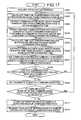
- FIG. 24is a diagram to explain such a preplan type failure recovery system.
- FIG. 24explains a network based on an optical path which transmits/receives an optical signal between terminals, particularly a network where the WDM technique is employed to multiplex a plurality of optical signals in an optical fiber and the OXC (Optical Cross Connect) is used for relaying.
- WDMWideband Division Multiple Access
- OXCOptical Cross Connect
- FIG. 24represents a case in which communication is preformed on an active communication path 3 between a communication node 1 and a communication node 2 .
- Each communication nodeis constructed by an optical cross connect as an optical switch.
- the communication path 3has communication nodes 17 , 10 , 12 , and 14 . Assuming that a failure 11 occurs between the communication nodes 10 and 12 , the downstream communication node 12 detects the failure.
- the optical cross connectcomprises a function of switching a connection state between a port at an optical signal inputting unit side and a port at an optical signal outputting unit side by adjusting an angle of an incorporated mirror (not shown).
- the communication node 12which has detected the failure, transfers a failure notification message 13 containing failure portion information to a communication node 14 , and the communication node 14 further notifies it to an adjacent communication node 15 , so that the message is sequentially notified to adjacent communication nodes (flooding).
- the communication nodes 15 and 16 on the backup communication path and the communication nodes 14 and 17 that switch the communication pathtransfer a failure notification message to all the adjacent communication nodes except the communication node that has received it only when the failure notification message is received for the first time. Then, the communication path is switched from the active communication path 3 to a backup communication path 4 according to the previously registered backup communication path information.
- the communication nodes 15 and 16 on the backup communication path on the set backup communication path or the communication nodes 14 and 17 that switch the communication pathare far away from the failure detected communication node 12 and it takes much time to receive the failure notification message, which largely causes delay of the communication path recovery.
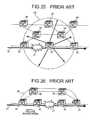
- FIG. 25is a schematic to explain a conventional backup communication path design system.
- communicationis performed on an active communication path of communication nodes 20 , 22 , and 23 .
- a time for transferring a failure notification message from a downstream communication node 22 to each communication nodeis calculated for a failure 21 between the communication nodes 20 and 22 .
- a communication node group which is present in an area 29 where the failure notification message can be transferred within the given limit timeis used to search for a backup communication path.
- the communication nodesare excluded from the communication node group to be retrieved.
- MPLSMulti-Protocol Label Switching
- an upstream communication node in the communication link where the failure has occurreddetects the failure occurrence and transmits a failure notification message to the downstream along the active communication path.
- the switching communication node which has received the failure notification messageswitches the communication path to the previously registered backup communication path.
- FIG. 26is a schematic of a conventional system of switching to a backup communication path in the MPLS communication network.
- communicationis performed on an active communication path 37 made of communication nodes 33 , 30 , 32 , and 34 .
- the upstream communication node 30 where the failure 31 has occurreddetects the failure, and transmits a failure notification message to the communication node 33 where a backup communication path 38 is set.
- the communication node 33 which has received the failure notification messageswitches the communication path to the backup communication path 38 .
- the communication node 33 which switches the communication pathis far away from the communication node 30 which has detected the failure and it takes much time to receive the failure notification message, which causes delay of the communication path recovery. But, as explained in FIG. 25 , a communication node which switches the communication path is selected from the communication node group on the active communication path 37 , which does not exceed the given limit time, to set the backup communication path so that the problem can be solved.
- a backup communication path design methodis a method in which backup communication path information is previously registered in each communication node of a communication network having a plurality of communication nodes, when a communication link failure or communication node failure occurs, a failure detected communication node transmits a failure notification message containing failure portion information to each communication node and a communication node which has received the failure notification message set up a communication path in parallel.
- the methodincludes selecting a communication node where a time for transferring the failure notification message from a plurality of failure detected communication nodes that detect a plurality of failures on an active communication path to be protected is within a predetermined time; and searching, using the communication nodes selected, for a common backup communication path that bypasses the failures.
- a backup communication path design apparatusis a device in which backup communication path information is previously registered in each communication node of a communication network having a plurality of communication nodes, when a communication link failure or communication node failure occurs, a failure detected communication node transmits a failure notification message containing failure portion information to each communication node and a communication node which has received the failure notification message set up a communication path in parallel.
- the apparatusincludes a selecting unit that selects a communication node where a time for transferring the failure notification message from a plurality of failure detected communication nodes that detect a plurality of failures on an active communication path to be protected is within a predetermined time; and a searching unit that searches, using the communication nodes selected, a common backup communication path that bypasses the failures.
- a computer program according to still another aspect of the present inventionrealizes the method according to the present invention on a computer.
- FIG. 1is a schematic to explain a backup communication path design processing according to a first embodiment of the present invention
- FIG. 2is a functional block diagram of a management communication node according to the first embodiment
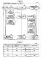
- FIG. 3is an example of contents of topology information shown in FIG. 2 ;
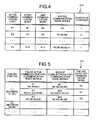
- FIG. 4is an example of contents of active communication path information shown in FIG. 2 ;
- FIG. 5is an example of contents of backup communication path information shown in FIG. 2 ;
- FIG. 6is a flowchart of a backup communication path design processing according to the first embodiment
- FIG. 7is a schematic to explain a failure notification area to which a failure notification message is transmitted from two adjacent communication nodes
- FIG. 8is a schematic to explain a backup communication path design processing according to a second embodiment of the present invention.
- FIG. 9is a functional block diagram of a management communication node according to the second embodiment.
- FIG. 10is a flowchart to explain a process procedure of the backup communication path design processing according to the second embodiment
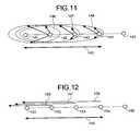
- FIG. 11is a schematic to explain a design processing of a backup communication path where switching is performed by flooding a failure notification message
- FIG. 12is a schematic to explain a design processing of a backup communication path where switching is performed by transferring a failure notification message to upstream communication nodes;
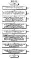
- FIG. 13is a flowchart to explain a process procedure of a backup communication path design processing according to a third embodiment of the present invention.
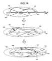
- FIG. 14is a schematic to explain a segment setting processing according to the third embodiment.
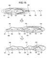
- FIG. 15is a schematic to explain a segment setting processing in which communication links are to be protected.
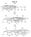
- FIG. 16is a schematic to explain a segment setting processing in which communication nodes are to be protected.
- FIG. 17is a flowchart to explain a process procedure of a backup communication path design processing according to a fourth embodiment of the present invention.
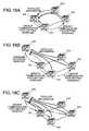
- FIG. 18Ais a schematic to explain a signaling processing of backup communication path setting which a management communication node performs on other communication nodes;
- FIG. 18Bis a schematic to explain a signaling processing of backup communication path setting which a management server performs on communication nodes;
- FIG. 18Cis a schematic to explain a backup communication path setting processing which the management server performs on communication nodes
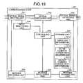
- FIG. 19is a functional block diagram of a communication node according to a fifth embodiment of the present invention.
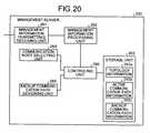
- FIG. 20is a functional block diagram of a management server according to the fifth embodiment.
- FIG. 21is a schematic to explain a control signal communication network and a user data communication network according to a sixth embodiment of the present invention.
- FIG. 22depicts functional block diagrams of a control signal communication node and a user data communication node according to the sixth embodiment
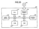
- FIG. 23is a block diagram to explain a structure of a computer according to a variant of the embodiments.
- FIG. 24is a diagram to explain a conventional preplan type failure recovery system
- FIG. 25is a diagram to explain a conventional backup communication path design system.
- FIG. 26is a diagram to explain a conventional system of switching to a backup communication path in the MPLS communication network.
- FIG. 1is a schematic to explain a backup communication path design processing according to a first embodiment of the present invention.
- communication nodes 47 and 48where a time for transferring a failure notification message from a plurality of failure detected communication nodes 42 , 43 , 44 , and 45 which detect a plurality of failures on an active communication path 40 to be protected is within a predetermined time are selected, and the selected communication nodes 47 and 48 are used to search for a backup communication path common to each failure which bypasses the failures.
- the failuremeans a failure in a communication link or in a communication node.
- a communication node connected to the communication linktransmits a failure notification message.
- the communication node where the failure has occurredtransmits a failure notification message, or when it is impossible, a communication node adjacent to the communication node where the failure has occurred transmits a failure notification message.
- a failure notification messageWhen a failure occurs in the communication node of the active communication path, a communication node downstream the failure detects the failure and transmits a failure notification message.
- failure notification areas 51 to 54 containing communication nodes where a time for transferring a failure notification message from each failure detected communication node 42 to 45 on the active communication path 40 is within a predetermined timeare obtained for each failure detected communication node 42 to 45 .
- the communication nodes 47 and 48 commonly contained in each failure notification area 51 to 54are extracted, and the extracted communication nodes 47 and 48 are used to design a common backup communication path which bypasses a plurality of failures which have occurred on the active communication path 40 to be protected.
- a communication node 49is outside the failure notification areas 51 and 52 respectively corresponding to the failure detected communication nodes 42 and 43 , it is excluded from the communication nodes which are used to construct the backup communication path.
- a communication node 50does not belong to any failure notification area 51 to 54 , it is excluded from the communication nodes which are used to construct the backup communication path.
- the time for transferring a failure notification messageis calculated from a sum of a propagation delay time when the transferred failure notification message passes through the communication link and a time for which the transferred failure notification message is input/output in each communication node.
- a failure recovery time required when a failure occursis composed of a time for transferring the failure notification message and a backup communication path switching time in which each communication node which has received the failure notification message switches to the backup communication path.
- the failure recovery timeis reduced by placing an upper limit on a time obtained by subtracting the backup communication path switching time from the failure recovery time, that is, the time for transferring the failure notification message.
- the common backup communication path which bypasses each failureis designed, thereby it is possible to design the backup communication path which recovers the communication within a predetermined recovery time while restricting communication resources on the failures on the communication path.
- the backup communication path designing processingis performed by the management communication node that manages the backup communication path.
- the management communication nodedesigns the backup communication path, and then transmits a backup communication path setting signaling message which requests information on the backup communication path and setting of the backup communication path on other communication nodes constructing the backup communication path.
- FIG. 2is a functional block diagram of a management communication node 60 according to the first embodiment.
- the management communication node 60has an optical signal inputting unit 61 , an optical switching unit 62 , an optical signal outputting unit 63 , a message receiving unit 64 , a message processing unit 65 , a message transmitting unit 66 , a storage unit 67 , an input monitoring unit 68 , a communication node selecting unit 69 , a backup communication path designing unit 70 , and a controlling unit 71 .
- the optical signal inputting unit 61is a receiving unit that receives an optical signal from an adjacent upstream communication node
- the optical signal outputting unit 63is an outputting unit that outputs the received optical signal to an adjacent downstream communication node.
- the optical switching unit 62is a switching unit that performs switching to the backup communication path when a failure occurs on the active communication path and the switching to the backup communication path is required in the communication node.
- a plurality of communication linksare connected to the optical signal inputting unit 61 and the optical signal outputting unit 63 , respectively, and one of the communication links is selected by the optical switching unit 62 to transmit/receive various data.
- the message receiving unit 64is a receiving unit that receives a failure notification message transmitted from an adjacent communication node.
- the failure notification messagecontains failure portion information for specifying a link where the failure has occurred.
- the massage processing unit 65is a processing unit that holds the failure notification message received by the message receiving unit 64 .
- the message processing unit 65holds only the first received failure notification message.
- the message processing unit 65retrieves the held failure notification messages, and determines whether or not the failure notification message newly received by the message receiving unit 64 is overlapped with the already-received failure notification message. In other words, the message processing unit 65 determines whether or not the failure notification message received in the message receiving unit 64 is the new failure notification message.
- the message processing unit 65issues an instruction of transmitting the failure notification message to the message transmitting unit 66 .
- the message transmitting unit 66transmits the failure notification message to the adjacent communication nodes based on the instruction from the message processing unit 65 .
- the message processing unit 65issues the instruction to the message transmitting unit 66 , and then refers to backup communication path information 67 c stored in the storage unit 67 described later and issues an instruction of switching the communication path from the active communication path to the backup communication path to the optical switching unit 62 .
- the message processing unit 65creates a failure notification message containing information on the failure on the communication link basis and the failure detected communication node (self-communication node), and causes the message transmitting unit 66 to transmit the created failure notification message.
- the failure notification messageis notified to other communication nodes by flooding.
- the message processing unit 65performs backup communication path setting signaling for transmitting the backup communication path information and a request signal for setting the backup communication path based on the information with respect to the communication nodes which belong to the backup communication path.
- a protocolsuch as RSVP-TE (Resource reSerVation Protocol with Traffic Engineering) is used for the backup communication path setting signaling.
- the message processing unit 65transmits a message for requesting to transmit topology information to the other communication nodes via the message transmitting unit 66 , and acquires the correspondingly transmitted topology information and stores it in the storage unit 67 as the topology information 67 a .
- a protocolsuch as OSPF (Open Shortest Path First) is used for the information collecting.
- the storage unit 67is a storage device capable of storing various information, and stores the topology information 67 a , active communication path information 67 b , and backup communication path information 67 c .
- the topology information 67 ais information indicating topology of the optical communication network where the backup communication path is to be designed.
- FIG. 3is a diagram to explain one example of the topology information 67 a shown in FIG. 2 .
- the topology information 67 ais information collected by the message processing unit 66 or information where user inputted information is stored.
- the topology information 67 ais information on the communication link which connects the communication nodes constructing the optical communication network, and contains information on the communication link, one communication node connected through the communication link, the other communication node connected through the communication link, and a length of the communication link.
- the active communication path information 67 bis information on the active communication path set on the optical communication network.
- FIG. 4is a diagram to explain one example of the active communication path information 67 b shown in FIG. 2 .
- the active communication path information 67 bis composed of information on the active communication path, the start communication node of the active communication path, the end communication node of the active communication path, a routed communication node series present between the start communication node and the end communication node, and the number of channels.
- the backup communication path information 67 cis information on the backup communication path for switching from the active communication path when a failure occurs.
- FIG. 5is a diagram to explain one example of the backup communication path information 67 c shown in FIG. 2 .
- the backup communication path information 67 ccontains information on the failure portion, the failed active communication path, the backup communication path, and the failure detected communication node.
- the failure portionmeans that a portion where a failure occurs in the optical communication network is indicated by the communication link (between communication node-communication node). For example, a communication link L 1 (between N 1 -N 2 ) indicates that a failure has occurred in the communication link L 1 between the communication node N 1 and the communication node N 2 .
- the failed active communication pathmeans that the active communication path containing the failure potion is indicated by a communication node series.
- P 1 (N 1 , N 2 )indicates the failed active communication path where the communication node N 1 is the start point and the communication node N 2 is the end point.
- the backup communication pathis a communication path which is previously determined so as to correspond to the failed active communication path on one-to-one basis and which is a switch destination when a failure occurs.
- the backup communication pathis indicated by the communication node series.
- SP 1N 1 , N 4 , N 5 , N 2
- SP 1indicates the backup communication path where the communication node N 1 is the start point, the communication node 4 and the communication node 5 are routed, and the communication node N 2 is the end point.
- the failure detected communication nodeis a communication node which is positioned downstream with respect to the failure which has occurred on the active communication path and detects the failure by disconnection (disable reception) of the optical signal.
- each communication node which has received the failure notification messagerefers to the backup communication path information 67 c , and switches the communication path from the failed active communication path P 1 to the backup communication path SP 1 .
- the input monitoring unit 68is a monitoring unit that monitors a state of an optical signal input into the optical signal inputting unit 61 .
- the input monitoring unit 68makes a request to the message processing unit 65 to transmit a failure notification message.
- the communication node selecting unit 69is a selecting unit that selects a communication node where the time for transferring the failure notification message from a plurality of failure detected communication nodes on the active communication path to be protected, which detect the failures, is within a predetermined time.
- the time for transferring the failure notification messageis calculated by assuming the sum of the propagation delay time when the transferred failure notification message passes through the communication link and the time for which the transferred failure notification message is input/output in each communication node as the communication cost, and using a communication path search algorithm represented by Dijkstra or the like.
- the backup communication path designing unit 70is a designing unit that uses communication nodes selected by the communication node selecting unit 69 to design the common backup communication path which bypasses a plurality of failures when the failures occur.
- the backup communication path designing unit 70designs the backup communication path whose bypass distance is the minimum by assuming a distance of the communication link as a cost and using the communication path search algorithm represented by Dijkstra or the like.
- the backup communication path designing unit 70designs the backup communication path whose additional preliminary communication capacity is the minimum.
- the preliminary communication capacityis a communication capacity which has been reserved for the bypass communication. Even when a plurality of backup communication paths are set for one communication link, since the backup communication paths are remarkably rare used at the same time, the capacity of the backup communication path which consumes the communication capacity most is only saved.
- the backup communication path designing unit 70may design the backup communication path whose distance between the start communication node and the end communication node on the active communication path is maximum or minimum.
- the backup communication path designing unit 70designs the backup communication path whose additional preliminary communication capacity is the minimum by setting the additional preliminary communication capacity obtained by subtracting the preliminary communication capacity already reserved by the other backup communication path from the preliminary communication capacity required for setting a new backup communication path as the cost of each communication link, and applying the communication path search algorithm represented by Dijkstra or the like.
- the backup communication path designing unit 70stores information on the designed backup communication path in the storage unit 67 as the backup communication path information 67 c.
- the backup communication path designing unit 70instructs the message processing unit 65 to perform backup communication path setting signaling on the communication nodes which belong to the backup communication path.
- the controlling unit 72is a controlling unit that performs the entire control of the management communication node 60 and controls transmission/reception of various data between the respective functioning units.
- the functional structure of the management communication node 60 that designs the backup communication pathhas been explained, but the functional structure of other communication node may employ a functioning unit that designs the backup communication path from the functioning unit of the management communication node 60 , that is, a functioning unit where the communication node selecting unit 69 and the backup communication path designing unit 70 are excluded.
- the message processing unit of the other communication nodehas a function of, when the backup communication path setting signaling is received from other communication node, setting the backup communication path on the self-communication node and performing the backup communication path setting signaling on the adjacent communication nodes which belong to the backup communication path.
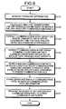
- FIG. 6is a flowchart to explain the process procedure of the backup communication path design processing according to the first embodiment.
- the communication node selecting unit 69first acquires the topology information 67 a stored in the storage unit 67 (step S 101 ), and calculates a time for transferring a failure notification message from a failure portion ⁇ i ⁇ in each communication link on the active communication path to be protected (step S 102 ).
- the communication node selecting unit 69extracts a communication node group ⁇ Gi ⁇ where the transfer time is within a designed time for each failure portion ⁇ i ⁇ (step S 103 ), and further extracts a communication node group commonly contained in each extracted node group ⁇ i ⁇ as a backup path enabled node group G (step S 104 ).
- the backup communication path designing unit 70searches for the backup communication path which is constructed by the communication nodes belonging to the backup path enabled node group G and conforms to a predetermined reference (step S 105 ).
- the predetermined referencemeans a backup communication path design reference such as a minimum bypass distance, a minimum preliminary communication capacity, a maximum distance between the start and end communication nodes, or a minimum distance between the start and end communication nodes.
- the backup communication path designing unit 70stores the searched backup communication path in the backup communication path information 67 c (step S 106 ), and the message processing unit 65 transmits a request of setting the backup communication path to other communication nodes (step S 107 ), and the backup communication path setting processing is terminated.
- the communication node selecting unit 69selects the communication node where the time for transferring a failure notification message from a plurality of failure detected communication nodes which detect the failures on the active communication path to be protected is within a predetermined time, and the backup communication path designing unit 70 uses the selected communication nodes to search for the common backup communication path which bypasses a plurality of failures when the failures occur.
- the backup communication pathwhich recovers the communication within a predetermined recovery time while restricting the communication resources with respect to the failures on the communication path.
- the communication node selecting unit 69calculates the time for transferring the failure notification message based on the propagation delay time when the transferred failure notification message passes through the communication link and the time for which the transferred failure notification message is input/output in each communication node. Thus, the required recovery time can be accurately calculated.
- the backup communication path designing unit 70uses the communication nodes selected by the communication node selecting unit 69 to search for the backup communication path whose distance between the start communication node and the end communication node on the active communication path is maximum.
- the distance of the backup communication pathis made large so that the backup communication is easily shared and the communication resources can be restricted.
- the backup communication path designing unit 70uses the communication nodes selected by the communication node selecting unit 69 to search for the backup communication path whose distance between the start communication node and the end communication node is the minimum.
- the distance of the backup communication pathis made small so that the recovery time can be reduced.
- the backup communication path designing unit 70searches for the backup communication path whose bypass distance is the minimum.
- the propagation delay of a signal due to increase in the communication distancecan be restricted.
- the backup communication path designing unit 70searches for the backup communication path whose preliminary communication capacity reserved for failure bypassing is the minimum.
- the backup communication path whose communication resources are restrictedcan be designed.
- the message processing unit 65transmits a request signal for requesting to set the backup communication path in the communication nodes contained in the backup communication path based on the information on the backup communication path searched by the backup communication path designing unit 70 , and performs the path setting signaling which requests to transfer the request signal to the adjacent communication nodes of the communication node.
- the communication node 60can design the backup communication path to set the backup communication path on the other communication nodes.
- the backup communication path capable of recovering the communication within the predetermined recovery timeis designed when the communication node downstream a failure portion detects the failure according to the first embodiment, when each communication link makes bidirectional communication, the backup communication path capable of recovering the communication within the predetermined recovery time may be designed when any one of the communication nodes across the failure portion detects the failure.
- FIG. 7is a schematic to explain a failure notification area to which a failure notification message is transferred from two adjacent communication nodes
- FIG. 8is a schematic to explain the backup communication path design processing according to the second embodiment.
- a communication node groupwhere the time for transferring a failure notification message from one of communication nodes 81 and 83 on an active communication path 80 that detects a failure 82 is within a predetermined time is first extracted in the backup communication path design processing.
- an area contained in either one of an area 90 where the failure notification message is transferred from the communication node 81 within the designated limit time and an area 91 where the failure notification message is transferred from the communication node 83 within the designated limit timeis set as the failure notification area. This processing is performed on each communication link on the active communication path to be protected to set the failure notification area for each communication link.
- communication nodes 106 and 107 commonly contained in each set failure notification areaare extracted, and the extracted communication nodes 106 and 107 are used to design a common backup communication path which bypasses a plurality of failures occurring on an active communication path 100 to be protected.
- a communication node 108Since a communication node 108 is outside a failure notification area 110 corresponding to communication nodes 101 and 102 and a failure notification area 111 corresponding to communication nodes 102 and 103 , it is excluded from the communication nodes used for constructing the backup communication path. Similarly, since a communication node 109 does not belong to any one of the failure notification areas 110 to 113 , it is excluded from the communication nodes used for constructing the backup communication path.
- FIG. 9is a diagram to explain a functional structure or a management communication node 73 according to the second embodiment. A detailed explanation on the functioning units having the same functions as the functioning units explained in FIG. 2 will be omitted.
- the management communication node 120has optical signal inputting/outputting units 121 and 123 , an optical switching unit 122 , message transmitting/receiving units 124 and 126 , a message processing unit 125 , a storage unit 127 , input monitoring units 128 and 129 , a communication node selecting unit 130 , a backup communication path designing unit 131 , and a controlling unit 132 .
- the optical signal inputting/outputting unit 121is an inputting/outputting unit that receives an optical signal from an adjacent upstream communication node and outputs the optical signal received by the optical signal inputting/outputting unit 123 to an adjacent downstream communication node.
- the optical signal inputting/outputting unit 123is an inputting/outputting unit that receives an optical signal from an adjacent upstream communication node and outputs the optical signal received by the optical signal inputting/outputting unit 121 to an adjacent downstream communication node.
- the optical switching unit 122is a functioning unit corresponding to the function of the optical switching unit 62 explained in FIG. 2 , and is a switching unit that, when a failure occurs on the active communication path and switching to a backup communication path is required in the communication node, switches to the backup communication path.
- the message transmitting/receiving units 124 and 126are a transmitting/receiving unit that receives a failure notification message transmitted from an adjacent communication node and transmits the failure notification message to another adjacent communication node.
- the message processing unit 125is a functioning unit corresponding to the function of the message processing unit 65 explained in FIG. 2 , and is a processing unit that holds the failure notification message received by the message transmitting/receiving units 124 and 126 .
- the message processing unit 125retrieves the held failure notification message and determines whether or not the failure notification message newly received by the message transmitting/receiving unit 124 or 126 is overlapped with the already received failure notification message.
- the message processing unit 125issues an instruction of transmitting the failure notification message to the message transmitting/receiving unit 124 or 126 .
- the message processing unit 125issues the instruction to the message transmitting/receiving unit 124 or 126 , and then refers to backup communication path information 127 c stored in the storage unit 127 and outputs an instruction of switching the communication path to the optical switching unit 122 .
- the message processing unit 125creates a failure notification message containing information on the failure on the communication link basis and the failure detected communication node (self-communication node), and causes the message transmitting/receiving unit 124 or 126 to transmit the created failure notification message.
- the message processing unit 125transmits the backup communication path information 127 c designed by the backup communication path designing unit 131 to the communication nodes which belong to the backup communication path, and performs backup communication path setting signaling which requests the communication nodes to set the backup communication path based on the transmitted backup communication path information 127 c.
- the message processing unit 125transmits a message for requesting other communication node to transmit the topology information via the message transmitting/receiving units 124 and 126 , and acquires the correspondingly transmitted topology information and stores it in the storage unit 127 as the topology information 127 a.
- the storage unit 127is a functioning unit corresponding to the function of the storage unit 67 explained in FIG. 2 , and stores the topology information 127 a , active communication path information 127 b , and the backup communication path information 127 c .
- the topology information 127 a , the active communication path information 127 b , and the backup communication path information 127 care information similar to the topology information 67 a , the active communication path information 67 b , and the backup communication path information 67 c explained in FIGS. 3 , 4 , and 5 .
- the input monitoring units 128 and 129are a monitoring unit that monitors a state of an optical signal input into the optical signal inputting/outputting units 121 and 123 , respectively.
- the input monitoring unit 128 or 129requests the message processing unit 125 to transmit a failure notification message.
- the communication node selecting unit 130extracts the communication node group where the time for transferring a failure notification message from any one of the failure detected communication nodes that detect a single failure is within a predetermined time for each failure, and selects a communication node commonly contained in the communication node group extracted for each failure.
- the failure notification areawhere the time for transferring a failure notification message from one of the two communication nodes that detect a failure is within a predetermined time is calculated, and a communication node group commonly contained in the calculated failure notification area is extracted for each failure.
- the backup communication path designing unit 131is a functioning unit corresponding to the function of the backup communication path designing unit 70 explained in FIG. 2 , and is a designing unit that uses the communication nodes selected by the communication node selecting unit 130 to design the common backup communication path which bypasses a plurality of failures when the failures occur based on the design reference such as a minimum bypass distance, a minimum preliminary communication capacity, a maximum distance between the start and end communication nodes, or a minimum distance between the start and end communication nodes.
- the controlling unit 132is a functioning unit corresponding to the function of the controlling unit 71 explained in FIG. 2 , and a controlling unit that performs the entire control of the management communication node 120 such as controlling transmission/reception of various data between the respective functioning units.
- FIG. 10is a flowchart to explain the process procedure of the backup communication path design processing according to the second embodiment.
- the communication node selecting unit 130first acquires the topology information 127 a stored in the storage unit 127 (step S 201 ), and calculates the time for transferring a failure notification message from each failure detected communication node on the active communication path to be protected (step S 202 ).
- the communication node selecting unit 130extracts the communication node group ⁇ Gi ⁇ where the time for transferring a failure notification message from either one failure detected communication node out of a pair ⁇ i ⁇ of the two adjacent failure detected communication nodes, which is connected through the communication link, is within a predetermined time for each failure detected communication node pair ⁇ i ⁇ (step S 203 ), and extracts a communication node group commonly contained in each extracted node group ⁇ Gi ⁇ as the backup path enabled node group G (step S 204 ).
- the backup communication path designing unit 131searches for the backup communication path which is constructed by the communication nodes belonging to the backup path enabled node group G and conforms to a predetermined reference (step S 205 ).
- the predetermined referenceis a backup communication path design reference such as a minimum bypass distance, a minimum preliminary communication capacity, a maximum distance between the start and end communication nodes, or a minimum distance between the start and end communication nodes.
- the backup communication path designing unit 131stores the searched backup communication path in the backup communication path information 127 c (step S 206 ), the message processing unit 125 transmits a request of setting the backup communication path to other communication nodes (step S 207 ), and the backup communication path setting processing is terminated.
- the communication node selecting unit 130extracts the communication node where the time for transferring a failure notification message from any one of the failure detected communication nodes that detect a single failure on the active communication path to be protected is within a predetermined time for each failure, and selects the communication node commonly contained in the extracted communication node for each failure. Therefore, it is possible to design the backup communication path which recovers the communication within a predetermined recovery time while restricting the communication resources for the failures on the communication path even in the communication network composed of the communication links where bidirectional communication is performed.
- the backup path enabled node group capable of transferring a failure notification message within a predetermined timeis extracted and the communication nodes commonly contained in the extracted backup path enabled node group are used to design the backup communication path. But in a communication network where when a switching communication node on the active communication path receives a failure notification message, the communication path is switched to the previously registered backup communication path as in the MPLS communication network, a bypass communication node assuming as the start communication node the communication node on the active communication path where the time for transferring a failure notification message from the failure detected communication node is within a predetermined time may be searched for.
- a bypass communication nodeis searched for that selects a communication node on the active communication path where the time for transferring a failure notification message from a failure detected communication node is within a predetermined time and assumes the selected communication node as the start communication node.
- FIG. 11is a schematic to explain the backup communication path design processing where switching is performed by flooding a failure notification message.
- a communication node 141where the time for transferring a failure notification message by flooding from a plurality of failure detected communication nodes 142 , 143 , and 144 that detect the failures on an active communication path 140 to be protected is within a predetermined time is selected, and a backup communication path which assumes the selected communication node 141 as the start communication node is searched for.
- failure notification areas 146 , 147 , and 148 to which the failure notification message is transferred from each of the failure detected communication nodes 142 , 143 , and 144 on the active communication path 140 to be protected within a designated limit timeare set, and the backup communication path which assumes the communication node 141 commonly contained in each of the failure notification areas 146 , 147 , and 148 as the start communication node is searched for.
- the candidates of the backup communication path having the start communication node on the active communication pathare previously registered.
- the start communication node of the backup communication pathis determined according to the processing so that the backup communication path to be actually used is extracted.
- FIG. 12is a schematic to explain a design processing of the backup communication path where switching is performed by transferring a failure notification message to upstream communication nodes.
- FIG. 11explains the case where the failure detected communication node floods the failure notification message, but
- FIG. 12explains a case where the failure notification message is transferred to the upstream communication nodes along the active communication path.
- a communication node 151where the time for transferring a failure notification massage to the upstream communication nodes along the active communication path from a plurality of failure detected communication nodes 152 , 153 , and 154 that detect the failures on an active communication path 150 to be protected is within a predetermined time is selected, and a backup communication path which assumes the selected communication node 151 as the start communication node is searched for.
- failure notification areas 156 , 157 , and 158where a failure notification message is transferred from each of the failure detected communication nodes 152 , 153 , and 154 on the active communication path 150 to be protected along the active communication path within a designated limit time are set and a backup communication path which assumes the communication node 151 commonly contained in each of the failure notification areas 156 , 157 , and 158 as the start communication node is searched for.
- the candidates of the backup communication path having the start communication node on the active communication pathare previously registered, and the start communication node of the backup communication path is determined according to the processing so that the backup communication path to be actually used is extracted.
- a functional structure of the management communication node according to the third embodimentis almost similar to the functional structure of the management communication node 60 according to the first embodiment shown in FIG. 2 .
- the message transmitting unit according to the third embodimenttransfers a failure notification message to the communication nodes on the active communication path by flooding as shown in FIG. 11 .
- the message transmitting unit according to the third embodimenttransfers a failure notification message to the communication nodes on the active communication path along the active communication path.
- the backup communication path information stored in the storage unit according to the third embodimentstores not only information on the already defined backup communication path but also information on the communication path which has the start communication node on the active communication path and which is to be a candidate of the backup communication path.
- the communication node selecting unit according to the third embodimentselects a communication node on the active communication path where the time for transferring a failure notification message from a plurality of failure detected communication nodes which detect the failures[K 1 ] on the active communication path to be protected is within a predetermined time.
- the backup communication path designing unitsearches for the backup communication path which assumes the communication node selected by the communication node selecting unit as the start communication node from the candidates of the backup communication path previously stored in the backup communication path information.
- the numeral of the message transmitting unit according to the third embodimentis assumed as 66 a
- the numeral of the backup communication path information according to the third embodimentis assumed as 67 c 1
- the numeral of the communication node selecting unit according to the third embodimentis assumed as 69 a
- the numeral of the backup communication path designing unit according to the third embodimentis assumed as 70 a , and an explanation based thereon will be given.
- the other functioning unitsare denoted with like numerals identical to those of the respective functioning units in FIG. 2 .
- FIG. 13is a flowchart to explain the process procedure of the backup communication path design processing according to the third embodiment.
- the communication node selecting unit 69 afirst acquires the topology information 67 a stored in the storage unit 67 (step S 301 ), and calculates a time for transferring a failure notification message to the failure portion ⁇ i ⁇ of each communication link on the active communication path to be protected (step S 302 ).
- the time for transferring a failure notification messageis a transfer time when the failure notification message is transferred from the failure detected communication node by flooding or transferred to other communication nodes along the active communication path as explained in FIG. 11 or 12 .
- the communication node selecting unit 69 aextracts the communication node group ⁇ Gi ⁇ where the transfer time is within a designated time for each failure portion ⁇ i ⁇ (step S 303 ), and further extracts the communication node group commonly contained in each extracted node group ⁇ Gi ⁇ as the backup path enabled node group G (step S 304 ).
- the backup communication path designing unit 70 aacquires the information on the backup communication path which is to be a candidate from the backup communication path information 67 c 1 (step S 305 ), and searches for the backup communication path which assumes the communication node belonging to the backup path enabled node group G as the start communication node and conforms to a predetermined reference (step S 306 ).
- the predetermined referenceis a design reference such as a minimum bypass distance, a minimum preliminary communication capacity, a maximum distance between the start and end communication nodes, or a minimum distance between the start and end communication nodes.
- the backup communication path designing unit 70 astores the searched backup communication path in the backup communication path information 67 c 1 (step S 307 ), the message processing unit 65 transmits a request of setting the backup communication path to other communication nodes (step S 308 ), and the backup communication path setting processing is terminated.
- the communication node selecting unit 69 aselects the communication node on the active communication path where the time for transferring a failure notification message from a plurality of failure detected communication nodes which detect the failures on the active communication path to be protected is within a predetermined time, and the backup communication path designing unit 70 a searches for the backup communication path which assumes the communication node selected by the communication node selecting unit 69 a as the start communication node. Therefore, it is possible to design the backup communication path which recovers the communication within a predetermined time while restricting the communication resources for the failures on the communication path even in the backup communication path switching system such as the MPLS communication network.
- the backup communication path common to each failure, which bypasses the failures on the active communication path to be protectedis designed according to the first to the third embodiments. But when one bypass communication pass cannot bypass all the failure assumed portions on the active communication path to be protected, the backup communication path may be divided into several segments to design the backup communication path which bypasses the failures for each segment. In a fourth embodiment of the present invention, there will be explained a case where the backup communication path is divided into several segments and the backup communication path which bypasses the failures for each segment is designed.
- FIG. 14is a schematic to explain the segment setting processing according to the fourth embodiment.
- a failure notification area 166 containing the communication nodes where the time for transferring a failure notification message from a failure detected communication node 162 on an active communication path 160 to be protected is within a predetermined timeis obtained, and the communication nodes contained in the failure notification area 166 are used to search for a backup communication path 167 .
- a failure notification area 168 containing the communication nodes where the time for transferring a failure notification message from a failure detected communication node 163 adjacent to the failure detected communication node 162 is within a predetermined timeis obtained, and the communication nodes commonly contained in the failure notification areas 166 and 168 are used to search for the backup communication path which bypasses the failures detected by the failure notification nodes 162 and 163 .
- a searched backup communication path 169is set as a new backup communication path.
- a failure notification area 170 of a failure detected communication node 164 adjacent to the failure detected communication node 163is further obtained, and the communication nodes commonly contained in the failure notification areas 166 , 168 , and 170 are used to search for the backup communication path which bypasses each failure detected by the failure notification nodes 162 , 163 , and 164 .
- the backup communication path 169is set as a segment capable of bypassing a failure in a section of the active communication path sandwiched by the communication node 161 and the failure detected communication node 164 .
- a failure which is bypassed by the processingmay be any failure which occurs in the communication link or in the communication node.
- FIG. 15is a schematic to explain a segment setting processing which is to protect the communication link
- FIG. 16is a schematic to explain a segment setting processing which is to protect the communication node.
- FIG. 15explains a state where when the communication link of the active communication path having communication nodes 181 to 187 is to be protected, a segment 188 of the backup communication path which bypasses the failures in the communication link detected by the failure detected communication nodes 182 , 183 , and 184 (a communication link failure between the failure detected communication nodes 181 and 182 , a communication link failure between the failure detected communication nodes 182 and 183 , and a communication link failure between the failure detected communication nodes 183 and 184 ) is searched for.
- the segment 188 of the backup communication pathprotects the communication link failures in the section 180 sandwiched by the communication node 181 and the failure detected communication node 184 .
- the second segment 191 of the backup communication pathprotects the communication link failures in a section 190 sandwiched by the failure detected communication node 184 and the failure detected communication node 186 .
- Each segmentis set to protect the communication link of the active communication path to be protected without being overlapped with other segment like the segment 188 and the segment 191 of the backup communication path shown in FIG. 15 so that the communication resources can be utilized efficiently to cope with the communication link failures.
- FIG. 16explains a state where when communication nodes 202 to 207 on the active communication path are to be protected, a segment 208 of the backup communication path which bypasses the failures of the communication nodes 202 and 203 detected by the failure detected communication nodes 202 and 203 is searched for.
- the segment 208 of the backup communication pathis assumed to be an area 200 constructed by the failure detected communication nodes 202 and 203 .
- a segment 211 of the backup communication path which bypasses the failures of the communication nodes 204 and 205 detected by the failure detected communication nodes 204 and 205is searched for.
- the segment 211 of the backup communication pathis to be an area 210 constructed by the failure detected communication node 204 and the failure detected communication node 205 .
- a new segment 214 of the backup communication pathwhich protects the communication nodes such as the failure detected communication nodes 206 and 207 (which protects the communication failure in an area 213 ) is similarly searched for.
- Each segmentis set such that the start or end communication node of each segment on the backup communication path is protected by other segment like the segment 208 and the segment 211 of the backup communication path shown in FIG. 16 , and the segment 211 and the segment 214 , thereby the communication node failures can be accurately coped with.
- searching for the backup communication pathis begun from the start communication node of the active communication path to be protected in the structures shown in FIGS. 15 and 16 .
- searching for the backup communication pathmay be begun from the end communication node of the active communication path.
- searching for the backup communication pathmay be begun from both the start communication node and the end communication node of the active communication path.
- the functional structure of the management communication node according to the fourth embodimentis almost similar to the functional structure of the management communication node 60 according to the first embodiment shown in FIG. 2 .
- the backup communication path information stored in the storage unit according to the fourth embodimentstores the information on the backup communication path divided into each segment.
- the communication node selecting unitselects the communication node commonly contained in the failure notification area of each failure detection node as explained using FIG. 15 or FIG. 16 , and the backup communication path designing unit according to the fourth embodiment uses the communication nodes selected by the communication node selecting unit to divide into segments and retrieve for the backup communication path which bypasses a plurality of failures on the active communication path to be protected.
- the numeral of the backup communication path information according to the fourth embodimentis assumed as 67 c 2
- the numeral of the communication node selecting unit according to the fourth embodimentis assumed as 69 b
- the numeral of the backup communication path designing unit according to the fourth embodimentis assumed as 70 b , and an explanation based thereon will be given.
- the other functioning unitsare denoted with like numerals identical to those of the respective functioning units in FIG. 2 .
- FIG. 17is a flowchart to explain the process procedure of the backup communication path design processing according to the fourth embodiment.
- the communication node selecting unit 69 bfirst acquires the topology information 67 a stored in the storage unit 67 (step S 401 ), and calculates a time for transferring a failure notification message from each communication node on the active communication path to be protected (step S 402 ).
- the communication node selecting unit 69 bextracts a communication node group where the time for transferring a failure notification message from the failure detected communication node is within a designated time (step S 403 ), and further searches for the backup communication path which is constructed by the communication nodes contained in each extracted node group and conforms to a predetermined reference (step S 404 ).
- the predetermined referenceis a backup communication path design reference such as a minimum bypass distance, a minimum preliminary communication capacity, a maximum distance between the start and end communication nodes, and a minimum distance between the start and end communication nodes.
- the communication node selecting unit 69 bcalculates a time for transferring a failure notification message from the failure detection node adjacent to the failure detection node (step S 405 ), and extracts a communication node group where the time for transferring a failure notification message from the adjacent failure detected communication nodes is within a designated time (step S 406 ).
- the backup communication path designing unit 70 buses the communication nodes commonly contained in each extracted communication node group to search for the backup communication path which bypasses each failure detected by each failure detected communication node where the communication node group has been extracted and conforms to the predetermined reference (step S 407 ).
- the backup communication path designing unit 70 bchecks whether or not the backup communication path capable of bypassing each failure has been successfully searched for (step S 408 ).
- the processingproceeds to step S 405 , where the communication node selecting unit 69 b further calculates the time for transferring a failure notification message from the adjacent communication node and continues the subsequent processing.
- the backup communication path designing unit 70 bsets the backup communication path which has already been searched for successfully as segments (step S 409 ), and checks whether or not the failure detection node on the active communication path to be protected is further present adjacently (step S 410 ).
- step S 410When the failure detected communication node on the active communication path to be protected is further present adjacently (step S 410 , Yes), the processing proceeds to step S 402 , where the communication node selecting unit 69 b calculates the time for transferring a failure notification message from the failure detected communication node, and continues the subsequent processing.
- the backup communication path designing unit 70 bstores the information on the backup communication path for each segment, which has been searched for successfully, in the backup communication path information 67 c 2 (step S 411 ). Then, the message processing unit 65 transmits a request of setting the backup communication path to other communication nodes (step S 412 ), and the backup communication path setting processing is terminated.
- the backup communication path designing unit 70 buses the communication nodes selected by the communication node selecting unit 69 b to divide the backup communication path into a plurality of segments and search for the backup communication path which bypasses a plurality of failures on the active communication path to be protected. Therefore, even when the failures on the active communication path to be protected cannot be bypassed by one backup communication path, the backup communication path is designed for each segment so that the bypass enable path can be designed.
- the backup communication path designing unit 70 bsequentially adds adjacent communication nodes to set a segment where the number of communication nodes between the start communication node and the end communication node in the segment on the backup communication path is the maximum. Therefore, the distance of the segment on the backup communication path is made large so that the backup communication path is easily shared and the communication resources can be restricted.
- each segmentcan be set easily and efficiently.
- each segmentcan be set easily and efficiently.
- each segmentcan be set easily and efficiently.
- the backup communication path designing unit 70 bsince when the backup communication path for a communication link failure is searched for, the backup communication path designing unit 70 b sets a plurality of segments which protect the communication link of the active communication path to be protected without being overlapped with other segment, the communication resources can be efficiently used to cope with the communication link failure.
- the backup communication path designing unit 70 bsets a plurality of segments where the start or end communication node of each segment on the backup communication path is protected by other segment, the communication node failure can be accurately coped with.
- the backup communication pathis designed by the management communication node in the first to the fourth embodiments
- the backup communication pathmay be designed by a management server that manages the backup communication path.
- the management server that manages the backup communication pathdesigns the backup communication path.
- FIG. 18Ais a schematic to explain a backup communication path setting signaling processing which the management communication node performs for other communication nodes
- FIG. 18Bis a schematic to explain the backup communication path setting signaling processing which the management server performs for other communication nodes
- FIG. 18Cis a schematic to explain the backup communication path setting processing which the management server performs for other communication nodes.
- FIG. 18Aexplains a case where a management communication node 220 collects the topology information of each communication node and designs the backup communication path based on the collected topology information as explained in the first to the fourth embodiments.
- the management communication node 220performs the backup communication path setting signaling which requests a communication node 221 constructing the backup communication path to set information on the designed backup communication path and the backup communication path as a bypass path to be actually used.
- the communication node 221 which has been subjected to the backup communication path setting signalingfurther performs the backup communication path setting signaling on a communication node 222 constructing the backup communication path.
- the processingis performed on each communication node constructing the backup communication path so that the backup communication path can be set.
- FIG. 18Bexplains a case where a management server 230 that manages the backup communication path designs the backup communication path based on the topology information collected from each communication node.
- the management server 230transmits the information on the designed backup communication path to a communication node 231 , and requests the communication node 231 to activate the backup communication path setting signaling which requests each communication node to set the backup communication path as a bypass path to be actually used.
- the communication node 231which has received the request of activating the backup communication path setting signaling performs the backup communication path setting signaling on other communication node 232 constructing the backup communication path. This processing is performed on each communication node constructing the backup communication path so that the backup communication path can be set.
- FIG. 18Cexplains a case where the management server 230 that manages the backup communication path designs the backup communication path based on the topology information collected from each communication node similarly as in FIG. 18B , but FIG. 18C is different in that the management server 230 directly makes a request of setting the backup communication path to each communication node 241 constructing the designed backup communication path.
- FIG. 19is a functional block diagram of the communication node 231 shown in FIG. 18B .
- the communication node 231has an optical signal inputting unit 251 , an optical switching unit 252 , an optical signal outputting unit 253 , a message receiving unit 254 , a message processing unit 255 , a message transmitting unit 256 , a storage unit 257 , an input monitoring unit 258 , and a controlling unit 259 .
- a detailed descriptionwill be omitted on the functioning units having the same functions as those of the functioning units explained in FIG. 2 .
- the optical signal inputting unit 251is a receiving unit that receives an optical signal from an adjacent upstream communication node
- the optical signal outputting unit 253is an outputting unit that outputs the received optical signal to an adjacent downstream communication node.
- the optical switching unit 252is a switching unit that, when a failure occurs on the active communication path and switching to a backup communication path is required in the communication node, switches to the backup communication path.
- the message receiving unit 254is a receiving unit that receives a failure notification message transmitted from an adjacent communication node or a request of activating the backup communication path setting signaling transmitted from the management server 230
- the message transmitting unit 256is a transmitting unit that transmits a failure notification message to adjacent communication nodes and transmits the topology information on the self-communication node to the management server 230 .
- the message processing unit 255is a processing unit that holds a failure notification message received in the message receiving unit 254 .
- the message processing unit 255retrieves the held failure notification message to determine whether or not a failure notification message newly received by the message receiving unit 254 is overlapped with the already received failure notification message.
- the message processing unit 255issues an instruction of transmitting the failure notification message to the message transmitting unit 256 .
- the message processing unit 255issues the instruction to the message transmitting unit 256 , and then refers to backup communication path information 257 c stored in the storage unit 257 and issues an instruction of switching the communication path to the optical switching unit 252 .
- the message processing unit 255creates a failure notification message containing the information on the failures on the communication link basis and a failure detected communication node (self-communication node), and causes the message transmitting unit 256 to transmit the created failure notification message.
- the message processing unit 255transmits the information on the backup communication path designed by the management server 230 to each communication node, and performs the backup communication path setting signaling which requests the communication nodes constructing the backup communication path to set the backup communication path based on the transmitted backup communication path information.
- the backup communication path setting signalingis received from other communication node, the backup communication path is set in the self-communication node, and the backup communication path setting signaling is performed on the adjacent communication nodes which belong to the backup communication path.
- the storage unit 257stores the topology information 257 a , active communication path information 257 b , and the backup communication path information 257 c .
- the topology information 257 ais data in which the topology information of each communication node is stored.
- the active communication path information 257 bis information on the active communication path set on the optical communication network.
- the backup communication path information 257 cis information on the backup communication path designed by the management server 230 .
- the input monitoring unit 258is a monitoring unit that monitors a state of an optical signal input into the optical signal inputting unit 251 .
- the controlling unit 259is a controlling unit that performs the entire control of the communication node 231 , and controls transmission/reception of various data between the respective functioning units.
- FIG. 20is a functional block diagram of the management server 230 shown in FIG. 18B .
- the management server 230has a management information transmitting/receiving unit 261 , a management information processing unit 262 , a storage unit 263 , a communication node selecting unit 264 , a backup communication path designing unit 265 , and a controlling unit 266 .
- the management information transmitting/receiving unit 261is a transmitting/receiving unit that receives the topology information and the like transmitted from each communication node and transmits the backup communication path information or a request of activating the backup communication path setting signaling to the communication nodes.
- the management information processing unit 262stores the topology information received from each communication node in the storage unit 263 as the topology information 263 a .
- the management information processing unit 262is a processing unit that instructs the management information transmitting/receiving unit 261 to transmit the information on the backup communication path designed by the backup communication path designing unit 265 and the request of activating the backup communication path setting signaling.
- the management information processing unit 262transmits a message for requesting each communication node to transmit the topology information via the management information transmitting/receiving unit 261 , and acquires the correspondingly transmitted topology information to store it in the storage unit 263 as the topology information 263 a .
- the information collectinguses a protocol such as SNMP (Simple Network Management Protocol).
- the storage unit 263is a storage unit that stores the topology information 263 a , active communication path information 263 b , and backup communication path information 263 c .
- the topology information 263 ais data in which the topology information collected from each communication node is stored.
- the active communication path information 257 bis information on the active communication path set on the optical communication network.
- the backup communication path information 257 cis information on the backup communication path designed by the management server 230 .
- the communication node selecting unit 264is a selecting unit that selects a communication node on the active communication path to be protected, where the time for transferring a failure notification message from a plurality of failure detected communication nodes which detect the failures is within a predetermined time.
- the backup communication path designing unit 265is a designing unit that uses the communication nodes selected by the communication node selecting unit 264 to design the common backup communication path which bypasses a plurality of failures when the failures occur.
- the controlling unit 266is a controlling unit that performs the entire control of the management server 230 , and controls transmission/reception of various data between the respective functioning units.
- the functional structures of the management server 240 and the communication nodes 241 to 244 shown in FIG. 18Care almost similar to those of the management server 231 and the communication nodes 231 to 234 shown in FIGS. 19 and 20 .
- the message processing units of the communication nodes 241 to 244are different from the message processing units 255 of the communication nodes 231 to 234 in that when a request of setting the backup communication path is received from the management server 240 with the information on the backup communication path designed by the management server 240 , the information on the backup communication path is stored in the storage unit as the backup communication path information to set the backup communication path.
- the management information processing unit of the management server 240is different from the management information processing unit 262 of the management server 230 in that it instructs the management information processing unit to create the setting information which requests to set the backup communication path based on the information on the backup communication path designed by the backup communication path designing unit of the management server 240 and to transmit it to each communication node belonging to the backup communication path.
- the management information processing unit 262 of the management server 230transmits a request signal for requesting the communication nodes contained in the backup communication path to set the backup communication path based on the information on the backup communication path searched for by the backup communication path designing unit 265 , and activates in the communication nodes the path setting signaling which requests to transfer the request signal to adjacent communication nodes of the communication node. Therefore, the backup communication path can be designed by the management server independent of the communication node so that processing loads of the communication nodes can be reduced.
- the management information processing unit of the management server 240transmits a request signal for requesting each communication node contained in the backup communication path to set the backup communication path based on the information on the backup communication path searched for by the backup communication path designing unit. Therefore, the backup communication path can be designed by the management server independent of the communication node, and the management server directly requests each communication node to set the backup communication path so that processing loads of the communication nodes can be reduced.
- control signal communication network where control signals such as failure notification messages are communicated and the user data communication network where user data is communicatedare the same communication network in the first to the fifth embodiments, the control signal communication network and the user data communication network may be separate communication networks.
- control signal communication network and the user data communication networkare separate communication networks.
- FIG. 21is a schematic to explain the control signal communication network and the user data communication network according to the sixth embodiment.
- each user data communication node 272 to 278 that communicates user datais connected by a user data communication network 270
- each control signal communication node 279 to 284 that communicates a control signalis connected by a control signal communication network 271 .
- Each communication link constructing the user data communication network 270does not necessarily correspond to each communication link constructing the control signal communication network 271 .
- a communication link on the control signal communication network 271 corresponding to a communication link connecting the user data communication nodes 276 and 277is not present.
- each communication link constructing the user data communication network 270corresponds to each communication link constructing the control signal communication network 271
- the same communication networkmay be logically divided into the user data communication network 270 and the control signal communication network 271 to be utilized.
- a failure 274occurs on the active communication path, a user data communication node 275 which has detected the failure 274 notifies that the failure 274 has been detected to the control signal communication node 281 , and the control signal communication node 281 which has received the notification transmits a failure notification message to other adjacent control signal communication nodes by flooding.
- a control signal communication node groupwhere a time for transferring a failure notification message via the control signal communication network 271 to each control signal communication node is within a designated predetermined time is extracted based on the topology information of the control signal communication network 271 after the failure has been detected by the user data communication node which detects a plurality of failures.
- the topology information of the user data communication node group corresponding to the extracted control signal communication node groupis used to search for the backup communication path which bypasses a plurality of failures on the user data communication network.
- FIG. 22is a schematic to explain the functional structures of the control signal communication node and the user data communication node according to the sixth embodiment.
- the control signal communication node shown in FIG. 22is a management communication node having a function of designing a backup communication path.
- the user data communication node 300is constructed to be connected to a control signal communication node 290 so as to notify the detected failure.
- the control signal communication node 290has a message receiving unit 291 , a message processing unit 292 , a message transmitting unit 293 , an information transmitting/receiving unit 294 , a storage unit 295 , a communication node selecting unit 296 , a backup communication path designing unit 297 , and a controlling unit 298 .
- the message receiving unit 291is a receiving unit that receives a failure notification message transmitted from the adjacent control signal communication nodes and the backup communication path setting signaling
- the message transmitting unit 293is a transmitting unit that performs a processing of transmitting a failure notification message to the adjacent control signal communication nodes or a processing of transmitting the topology information on the self-communication node to the control signal communication nodes which design the backup communication path.
- the message processing unit 292is a processing unit that holds the failure notification message received in the message receiving unit 291 .
- the message processing unit 292retrieves the held failure notification message to determine whether or not a failure notification message newly received by the message receiving unit 291 is overlapped with the already received failure notification message.
- the message processing unit 292issues to the message transmitting unit 293 an instruction of transmitting the failure notification message.
- the message processing unit 292issues the instruction to the message transmitting unit 293 , and then refers to backup communication path information 295 c stored in the storage unit 295 and issues an instruction of switching the communication path to the backup communication path to the optical switching unit 252 of the user data communication node 300 via the information transmitting/receiving unit 294 .
- the message processing unit 292creates a failure notification message containing the information on the failure portion on the communication link basis and the user data communication node 300 which has detected the failure, and instructs the message transmitting unit 293 to transmit the created failure notification message.
- the message processing unit 292transmits the information on the backup communication path designed by the backup communication path designing unit 297 to each communication node, and performs the backup communication path setting signaling on the communication nodes constructing the backup communication path so as to set the backup communication path based on the transmitted backup communication path information.
- the message processing unit 292transmits a message for requesting to transmit the topology information to other control signal communication nodes via the message transmitting unit 293 , and acquires the correspondingly transmitted topology information to store it in the storage unit 295 as the topology information 295 a.
- the information transmitting/receiving unit 294is a transmitting/receiving unit that transmits/receives various information such as failure detection information with the user data communication node 300 .
- the storage unit 295is a storage unit that stores the topology information 295 a , active communication path information 295 b , and the backup communication path information 295 c.
- the topology information 295 ais data in which the information on the topology of each control signal communication node and each user data communication node is stored. Specifically, as explained in FIG. 3 , the communication link information of each control signal communication node and each user data communication node is stored. Since the user data communication network 270 and the control signal communication network 271 are separated, the topology information 295 a stores a table indicating the relationship between the control signal communication node and the user data communication node connected thereto.
- the active communication path information 295 bis information on the active communication path set on the optical communication network.
- the backup communication path information 295 cis information on the backup communication path designed by the management server 230 .
- the communication node selecting unit 296is a selecting unit that selects a control signal communication node where a time for transferring a failure notification message via the control signal communication network constructed by the control signal communication nodes from a plurality of user data communication nodes which detect the failures on the active communication path to be protected is within a predetermined time.
- the backup communication path designing unit 297is a designing unit that uses the user data communication nodes corresponding to the control signal communication nodes selected by the communication node selecting unit 296 to design the backup communication path on the user data communication network which bypasses a plurality of failures when the failures occur.
- the controlling unit 298is a controlling unit that performs the entire control of the control signal communication node 290 , and controls transmission/reception of various data between the respective functioning units.
- the user data communication node 300has an optical signal inputting unit 301 , an optical switching unit 302 , an optical signal outputting unit 303 , an information transmitting/receiving unit 304 , an input monitoring unit 305 , and a controlling unit 306 .
- the optical signal inputting unit 301is a receiving unit that receives an optical signal from an adjacent upstream communication node
- the optical signal outputting unit 303is an outputting unit that outputs the received optical signal to an adjacent downstream communication node.
- the optical switching unit 302is a switching unit that, when a failure occurs on the active communication path and switching to the backup communication path is required in the communication node, switches to the backup communication path.
- the information transmitting/receiving unit 304is a transmitting/receiving unit that transmits/receives various information such as failure detection information with the control signal communication node 290
- the input monitoring unit 305is a monitoring unit that monitors a state of an optical signal input in the optical signal inputting unit 301 .
- the input monitoring unit 305notifies that the failure has been detected to the message processing unit 292 of the control signal communication node 290 via the information transmitting/receiving unit 304 , and instructs to transmit the failure notification message.
- the controlling unit 306is a controlling unit that performs the entire control of the user data communication node 300 , and controls transmission/reception of various data between the respective functioning units.
- control signal communication node 290that designs the backup communication path
- functional structure of other control signal communication nodemay employ a functioning unit that designs the backup communication path from the functioning unit of the control signal communication node 290 , that is, a functioning unit where the communication node selecting unit 296 and the backup communication path designing unit 297 are excluded.
- the message processing unit of the other communication nodewhen the backup communication path setting signaling is received from the other communication node, the message processing unit of the other communication node has a function of setting the backup communication path in the self-communication node and performing the backup communication path setting signaling on the adjacent communication nodes which belong to the backup communication path.
- control signal communication node 290 and the user data communication node 300are the separate apparatuses here, but the functions of the control signal communication node 290 and the user data communication node 300 can be realized in a single communication node apparatus.
- the communication node selecting unit 296 of the control signal communication node 290selects a control signal communication node where the time for transferring a failure notification message via the control signal communication network 271 that transmits a control signal from a plurality of failures detected communication nodes on the active communication path to be protected is within a predetermined time, and the backup communication path designing unit 297 of the control signal communication node 290 uses the control signal communication nodes selected by the communication node selecting unit 296 to search for the backup communication path of the user data communication network 270 that bypasses a plurality of failures when the failures occur.
- the design processing of the backup communication path that bypasses a plurality of failuresis applied to the communication network constructed by optical fiber cables in the first to the sixth embodiments
- the present inventionis not limited thereto and may be applied to the communication network constructed by other transmission medium such as a metallic (lead wire) cable.
- a computer program that realizes the functions of the bypass path design apparatus and the bypass path design methodis recorded in a computer readable recording medium 500 shown in FIG. 23 , and the program recorded in the recording medium 500 may be read and executed by a computer 400 to realize each function of the embodiments.
- the computer 400is constructed by a CPU (Central Processing Unit) 410 that executes the program, an input device 420 such as keyboard or mouse, a ROM (Read Only Memory) 430 that stores various data, a RAM (Random Access Memory) 440 that stores arithmetic parameter, a reading device 450 that reads the program from the recording medium 500 , an output device 460 such as a display, and a bus 470 that connects the respective devices.
- a CPUCentral Processing Unit
- ROMRead Only Memory
- RAMRandom Access Memory
- the CPU 410reads the program recorded in the recording medium 500 via the reading device 450 , and then executes the program to realize the functions.
- the recording medium 500may employ an optical disk, a flexible disk, a hard disk, and the like.
- the programmay be introduced into the computer 400 via a network such as the Internet.
- a backup communication path which recovers communication within a predetermined recovery timecan be designed while restricting communication resources for the failures on the communication path.
- the backup communication pathcan be easily shared by increasing the distance of the backup communication path to restrict the communication resources.
- the recovery timecan be reduced.
- the propagation delay of a signal due to increase in the communication distancecan be restricted.
- the backup communication path which restricts the communication resourcescan be designed.
- the backup communication path which recovers the communication within a predetermined recovery timecan be designed while restricting the communication resources for the failures on the communication path even in the communication network composed of the communication links where bidirectional communication is performed.
- the backup communication path which recovers the communication within a predetermined timecan be designed while restricting the communication resources for the failures on the communication path even in the backup communication path switching system such as the MPLS communication network.
- the backup communication pathis designed for each segment so that the bypass enable path can be designed even when the failures on the active communication path to be protected cannot be bypassed by a single backup communication path.
- the backup communication pathis easily shared by increasing the distance of the segment in the backup communication path and the communication resources can be restricted.
- each segmentcan be set easily and efficiently.
- the communication resourcescan be used efficiently to cope with the communication link failure.
- the backup communication path which recovers the communication within a predetermined recovery timecan be designed while restricting the communication resources for the failures on the data communication path even when the communication network that transmits a control signal and the communication network that makes data communication are separate.
- the backup communication pathis designed by the communication node itself and the backup communication path can be set in other communication node.
- the backup communication pathcan be designed by the management server independent of the communication node and processing loads of the communication node can be reduced.
- the backup communication pathcan be designed by the management server independent of the communication node and that the management server directly requests each communication node to set the backup communication path so that the processing load of the communication node can be reduced.
Landscapes
- Engineering & Computer Science (AREA)
- Computer Networks & Wireless Communication (AREA)
- Signal Processing (AREA)
- Data Exchanges In Wide-Area Networks (AREA)
- Maintenance And Management Of Digital Transmission (AREA)
Abstract
Description
Claims (21)
Applications Claiming Priority (2)
| Application Number | Priority Date | Filing Date | Title |
|---|---|---|---|
| JP2003390969AJP4209758B2 (en) | 2003-11-20 | 2003-11-20 | Detour communication route design method |
| JP2003-390969 | 2003-11-20 |
Publications (2)
| Publication Number | Publication Date |
|---|---|
| US20050111350A1 US20050111350A1 (en) | 2005-05-26 |
| US7852752B2true US7852752B2 (en) | 2010-12-14 |
Family
ID=34587464
Family Applications (1)
| Application Number | Title | Priority Date | Filing Date |
|---|---|---|---|
| US10/878,085Expired - Fee RelatedUS7852752B2 (en) | 2003-11-20 | 2004-06-28 | Method and apparatus for designing backup communication path, and computer product |
Country Status (3)
| Country | Link |
|---|---|
| US (1) | US7852752B2 (en) |
| JP (1) | JP4209758B2 (en) |
| CN (1) | CN100525285C (en) |
Cited By (145)
| Publication number | Priority date | Publication date | Assignee | Title |
|---|---|---|---|---|
| US20090028561A1 (en)* | 2006-07-03 | 2009-01-29 | Huawei Technologies Co., Ltd. | Method, system and node device for realizing service protection in automatically switched optical network |
| US20090222687A1 (en)* | 2008-03-03 | 2009-09-03 | Nortel Networks Limited | Method and system for telecommunication apparatus fast fault notification |
| US20140189837A1 (en)* | 2011-07-15 | 2014-07-03 | Deutsche Telekom Ag | Method to enhance high availability in a secure telecommunications network, and telecommunications network comprising a plurality of remote nodes |
| US9608740B2 (en) | 2015-07-15 | 2017-03-28 | At&T Intellectual Property I, L.P. | Method and apparatus for launching a wave mode that mitigates interference |
| US9615269B2 (en) | 2014-10-02 | 2017-04-04 | At&T Intellectual Property I, L.P. | Method and apparatus that provides fault tolerance in a communication network |
| US9640850B2 (en) | 2015-06-25 | 2017-05-02 | At&T Intellectual Property I, L.P. | Methods and apparatus for inducing a non-fundamental wave mode on a transmission medium |
| US9667317B2 (en) | 2015-06-15 | 2017-05-30 | At&T Intellectual Property I, L.P. | Method and apparatus for providing security using network traffic adjustments |
| US9674711B2 (en) | 2013-11-06 | 2017-06-06 | At&T Intellectual Property I, L.P. | Surface-wave communications and methods thereof |
| US9685992B2 (en) | 2014-10-03 | 2017-06-20 | At&T Intellectual Property I, L.P. | Circuit panel network and methods thereof |
| US9705610B2 (en) | 2014-10-21 | 2017-07-11 | At&T Intellectual Property I, L.P. | Transmission device with impairment compensation and methods for use therewith |
| US9705561B2 (en) | 2015-04-24 | 2017-07-11 | At&T Intellectual Property I, L.P. | Directional coupling device and methods for use therewith |
| US9722318B2 (en) | 2015-07-14 | 2017-08-01 | At&T Intellectual Property I, L.P. | Method and apparatus for coupling an antenna to a device |
| US9729197B2 (en) | 2015-10-01 | 2017-08-08 | At&T Intellectual Property I, L.P. | Method and apparatus for communicating network management traffic over a network |
| US9735833B2 (en) | 2015-07-31 | 2017-08-15 | At&T Intellectual Property I, L.P. | Method and apparatus for communications management in a neighborhood network |
| US9742521B2 (en) | 2014-11-20 | 2017-08-22 | At&T Intellectual Property I, L.P. | Transmission device with mode division multiplexing and methods for use therewith |
| US9742462B2 (en) | 2014-12-04 | 2017-08-22 | At&T Intellectual Property I, L.P. | Transmission medium and communication interfaces and methods for use therewith |
| US9749013B2 (en) | 2015-03-17 | 2017-08-29 | At&T Intellectual Property I, L.P. | Method and apparatus for reducing attenuation of electromagnetic waves guided by a transmission medium |
| US9749053B2 (en) | 2015-07-23 | 2017-08-29 | At&T Intellectual Property I, L.P. | Node device, repeater and methods for use therewith |
| US9748626B2 (en) | 2015-05-14 | 2017-08-29 | At&T Intellectual Property I, L.P. | Plurality of cables having different cross-sectional shapes which are bundled together to form a transmission medium |
| US9762289B2 (en) | 2014-10-14 | 2017-09-12 | At&T Intellectual Property I, L.P. | Method and apparatus for transmitting or receiving signals in a transportation system |
| US9769020B2 (en) | 2014-10-21 | 2017-09-19 | At&T Intellectual Property I, L.P. | Method and apparatus for responding to events affecting communications in a communication network |
| US9769128B2 (en) | 2015-09-28 | 2017-09-19 | At&T Intellectual Property I, L.P. | Method and apparatus for encryption of communications over a network |
| US9768833B2 (en) | 2014-09-15 | 2017-09-19 | At&T Intellectual Property I, L.P. | Method and apparatus for sensing a condition in a transmission medium of electromagnetic waves |
| US9780834B2 (en) | 2014-10-21 | 2017-10-03 | At&T Intellectual Property I, L.P. | Method and apparatus for transmitting electromagnetic waves |
| US9788326B2 (en) | 2012-12-05 | 2017-10-10 | At&T Intellectual Property I, L.P. | Backhaul link for distributed antenna system |
| US9787412B2 (en) | 2015-06-25 | 2017-10-10 | At&T Intellectual Property I, L.P. | Methods and apparatus for inducing a fundamental wave mode on a transmission medium |
| US9793954B2 (en) | 2015-04-28 | 2017-10-17 | At&T Intellectual Property I, L.P. | Magnetic coupling device and methods for use therewith |
| US9793955B2 (en) | 2015-04-24 | 2017-10-17 | At&T Intellectual Property I, Lp | Passive electrical coupling device and methods for use therewith |
| US9793951B2 (en) | 2015-07-15 | 2017-10-17 | At&T Intellectual Property I, L.P. | Method and apparatus for launching a wave mode that mitigates interference |
| US9800327B2 (en) | 2014-11-20 | 2017-10-24 | At&T Intellectual Property I, L.P. | Apparatus for controlling operations of a communication device and methods thereof |
| US9820146B2 (en) | 2015-06-12 | 2017-11-14 | At&T Intellectual Property I, L.P. | Method and apparatus for authentication and identity management of communicating devices |
| US9838078B2 (en) | 2015-07-31 | 2017-12-05 | At&T Intellectual Property I, L.P. | Method and apparatus for exchanging communication signals |
| US9838896B1 (en) | 2016-12-09 | 2017-12-05 | At&T Intellectual Property I, L.P. | Method and apparatus for assessing network coverage |
| US9847850B2 (en) | 2014-10-14 | 2017-12-19 | At&T Intellectual Property I, L.P. | Method and apparatus for adjusting a mode of communication in a communication network |
| US9847566B2 (en) | 2015-07-14 | 2017-12-19 | At&T Intellectual Property I, L.P. | Method and apparatus for adjusting a field of a signal to mitigate interference |
| US9853342B2 (en) | 2015-07-14 | 2017-12-26 | At&T Intellectual Property I, L.P. | Dielectric transmission medium connector and methods for use therewith |
| US9860075B1 (en) | 2016-08-26 | 2018-01-02 | At&T Intellectual Property I, L.P. | Method and communication node for broadband distribution |
| US9866276B2 (en) | 2014-10-10 | 2018-01-09 | At&T Intellectual Property I, L.P. | Method and apparatus for arranging communication sessions in a communication system |
| US9865911B2 (en) | 2015-06-25 | 2018-01-09 | At&T Intellectual Property I, L.P. | Waveguide system for slot radiating first electromagnetic waves that are combined into a non-fundamental wave mode second electromagnetic wave on a transmission medium |
| US9866309B2 (en) | 2015-06-03 | 2018-01-09 | At&T Intellectual Property I, Lp | Host node device and methods for use therewith |
| US9871282B2 (en) | 2015-05-14 | 2018-01-16 | At&T Intellectual Property I, L.P. | At least one transmission medium having a dielectric surface that is covered at least in part by a second dielectric |
| US9871558B2 (en) | 2014-10-21 | 2018-01-16 | At&T Intellectual Property I, L.P. | Guided-wave transmission device and methods for use therewith |
| US9871283B2 (en) | 2015-07-23 | 2018-01-16 | At&T Intellectual Property I, Lp | Transmission medium having a dielectric core comprised of plural members connected by a ball and socket configuration |
| US9876571B2 (en) | 2015-02-20 | 2018-01-23 | At&T Intellectual Property I, Lp | Guided-wave transmission device with non-fundamental mode propagation and methods for use therewith |
| US9876605B1 (en) | 2016-10-21 | 2018-01-23 | At&T Intellectual Property I, L.P. | Launcher and coupling system to support desired guided wave mode |
| US9876264B2 (en) | 2015-10-02 | 2018-01-23 | At&T Intellectual Property I, Lp | Communication system, guided wave switch and methods for use therewith |
| US9882257B2 (en) | 2015-07-14 | 2018-01-30 | At&T Intellectual Property I, L.P. | Method and apparatus for launching a wave mode that mitigates interference |
| US9887447B2 (en) | 2015-05-14 | 2018-02-06 | At&T Intellectual Property I, L.P. | Transmission medium having multiple cores and methods for use therewith |
| US9893795B1 (en) | 2016-12-07 | 2018-02-13 | At&T Intellectual Property I, Lp | Method and repeater for broadband distribution |
| US9906269B2 (en) | 2014-09-17 | 2018-02-27 | At&T Intellectual Property I, L.P. | Monitoring and mitigating conditions in a communication network |
| US9904535B2 (en) | 2015-09-14 | 2018-02-27 | At&T Intellectual Property I, L.P. | Method and apparatus for distributing software |
| US9912382B2 (en) | 2015-06-03 | 2018-03-06 | At&T Intellectual Property I, Lp | Network termination and methods for use therewith |
| US9912033B2 (en) | 2014-10-21 | 2018-03-06 | At&T Intellectual Property I, Lp | Guided wave coupler, coupling module and methods for use therewith |
| US9912027B2 (en) | 2015-07-23 | 2018-03-06 | At&T Intellectual Property I, L.P. | Method and apparatus for exchanging communication signals |
| US9912419B1 (en) | 2016-08-24 | 2018-03-06 | At&T Intellectual Property I, L.P. | Method and apparatus for managing a fault in a distributed antenna system |
| US9911020B1 (en) | 2016-12-08 | 2018-03-06 | At&T Intellectual Property I, L.P. | Method and apparatus for tracking via a radio frequency identification device |
| US9913139B2 (en) | 2015-06-09 | 2018-03-06 | At&T Intellectual Property I, L.P. | Signal fingerprinting for authentication of communicating devices |
| US9917341B2 (en) | 2015-05-27 | 2018-03-13 | At&T Intellectual Property I, L.P. | Apparatus and method for launching electromagnetic waves and for modifying radial dimensions of the propagating electromagnetic waves |
| US9930668B2 (en) | 2013-05-31 | 2018-03-27 | At&T Intellectual Property I, L.P. | Remote distributed antenna system |
| US9927517B1 (en) | 2016-12-06 | 2018-03-27 | At&T Intellectual Property I, L.P. | Apparatus and methods for sensing rainfall |
| US9929755B2 (en) | 2015-07-14 | 2018-03-27 | At&T Intellectual Property I, L.P. | Method and apparatus for coupling an antenna to a device |
| US9948355B2 (en) | 2014-10-21 | 2018-04-17 | At&T Intellectual Property I, L.P. | Apparatus for providing communication services and methods thereof |
| US9948354B2 (en) | 2015-04-28 | 2018-04-17 | At&T Intellectual Property I, L.P. | Magnetic coupling device with reflective plate and methods for use therewith |
| US9948333B2 (en) | 2015-07-23 | 2018-04-17 | At&T Intellectual Property I, L.P. | Method and apparatus for wireless communications to mitigate interference |
| US20180107504A1 (en)* | 2016-10-14 | 2018-04-19 | Fujitsu Limited | Setting method for server apparatus and server apparatus |
| US9954286B2 (en) | 2014-10-21 | 2018-04-24 | At&T Intellectual Property I, L.P. | Guided-wave transmission device with non-fundamental mode propagation and methods for use therewith |
| US9954287B2 (en) | 2014-11-20 | 2018-04-24 | At&T Intellectual Property I, L.P. | Apparatus for converting wireless signals and electromagnetic waves and methods thereof |
| US9967173B2 (en) | 2015-07-31 | 2018-05-08 | At&T Intellectual Property I, L.P. | Method and apparatus for authentication and identity management of communicating devices |
| US9973940B1 (en) | 2017-02-27 | 2018-05-15 | At&T Intellectual Property I, L.P. | Apparatus and methods for dynamic impedance matching of a guided wave launcher |
| US9991580B2 (en) | 2016-10-21 | 2018-06-05 | At&T Intellectual Property I, L.P. | Launcher and coupling system for guided wave mode cancellation |
| US9997819B2 (en) | 2015-06-09 | 2018-06-12 | At&T Intellectual Property I, L.P. | Transmission medium and method for facilitating propagation of electromagnetic waves via a core |
| US9999038B2 (en) | 2013-05-31 | 2018-06-12 | At&T Intellectual Property I, L.P. | Remote distributed antenna system |
| US9998870B1 (en) | 2016-12-08 | 2018-06-12 | At&T Intellectual Property I, L.P. | Method and apparatus for proximity sensing |
| US10009063B2 (en) | 2015-09-16 | 2018-06-26 | At&T Intellectual Property I, L.P. | Method and apparatus for use with a radio distributed antenna system having an out-of-band reference signal |
| US10009067B2 (en) | 2014-12-04 | 2018-06-26 | At&T Intellectual Property I, L.P. | Method and apparatus for configuring a communication interface |
| US10020844B2 (en) | 2016-12-06 | 2018-07-10 | T&T Intellectual Property I, L.P. | Method and apparatus for broadcast communication via guided waves |
| US10027397B2 (en) | 2016-12-07 | 2018-07-17 | At&T Intellectual Property I, L.P. | Distributed antenna system and methods for use therewith |
| US10027398B2 (en) | 2015-06-11 | 2018-07-17 | At&T Intellectual Property I, Lp | Repeater and methods for use therewith |
| US10033108B2 (en) | 2015-07-14 | 2018-07-24 | At&T Intellectual Property I, L.P. | Apparatus and methods for generating an electromagnetic wave having a wave mode that mitigates interference |
| US10044409B2 (en) | 2015-07-14 | 2018-08-07 | At&T Intellectual Property I, L.P. | Transmission medium and methods for use therewith |
| US10069535B2 (en) | 2016-12-08 | 2018-09-04 | At&T Intellectual Property I, L.P. | Apparatus and methods for launching electromagnetic waves having a certain electric field structure |
| US10079661B2 (en) | 2015-09-16 | 2018-09-18 | At&T Intellectual Property I, L.P. | Method and apparatus for use with a radio distributed antenna system having a clock reference |
| US10090594B2 (en) | 2016-11-23 | 2018-10-02 | At&T Intellectual Property I, L.P. | Antenna system having structural configurations for assembly |
| US10090606B2 (en) | 2015-07-15 | 2018-10-02 | At&T Intellectual Property I, L.P. | Antenna system with dielectric array and methods for use therewith |
| US10103422B2 (en) | 2016-12-08 | 2018-10-16 | At&T Intellectual Property I, L.P. | Method and apparatus for mounting network devices |
| US10103801B2 (en) | 2015-06-03 | 2018-10-16 | At&T Intellectual Property I, L.P. | Host node device and methods for use therewith |
| US10135145B2 (en) | 2016-12-06 | 2018-11-20 | At&T Intellectual Property I, L.P. | Apparatus and methods for generating an electromagnetic wave along a transmission medium |
| US10136434B2 (en) | 2015-09-16 | 2018-11-20 | At&T Intellectual Property I, L.P. | Method and apparatus for use with a radio distributed antenna system having an ultra-wideband control channel |
| US10135146B2 (en) | 2016-10-18 | 2018-11-20 | At&T Intellectual Property I, L.P. | Apparatus and methods for launching guided waves via circuits |
| US10135147B2 (en) | 2016-10-18 | 2018-11-20 | At&T Intellectual Property I, L.P. | Apparatus and methods for launching guided waves via an antenna |
| US10139820B2 (en) | 2016-12-07 | 2018-11-27 | At&T Intellectual Property I, L.P. | Method and apparatus for deploying equipment of a communication system |
| US10144036B2 (en) | 2015-01-30 | 2018-12-04 | At&T Intellectual Property I, L.P. | Method and apparatus for mitigating interference affecting a propagation of electromagnetic waves guided by a transmission medium |
| US10148016B2 (en) | 2015-07-14 | 2018-12-04 | At&T Intellectual Property I, L.P. | Apparatus and methods for communicating utilizing an antenna array |
| US10170840B2 (en) | 2015-07-14 | 2019-01-01 | At&T Intellectual Property I, L.P. | Apparatus and methods for sending or receiving electromagnetic signals |
| US10168695B2 (en) | 2016-12-07 | 2019-01-01 | At&T Intellectual Property I, L.P. | Method and apparatus for controlling an unmanned aircraft |
| US10178445B2 (en) | 2016-11-23 | 2019-01-08 | At&T Intellectual Property I, L.P. | Methods, devices, and systems for load balancing between a plurality of waveguides |
| US10205655B2 (en) | 2015-07-14 | 2019-02-12 | At&T Intellectual Property I, L.P. | Apparatus and methods for communicating utilizing an antenna array and multiple communication paths |
| US10225025B2 (en) | 2016-11-03 | 2019-03-05 | At&T Intellectual Property I, L.P. | Method and apparatus for detecting a fault in a communication system |
| US10224634B2 (en) | 2016-11-03 | 2019-03-05 | At&T Intellectual Property I, L.P. | Methods and apparatus for adjusting an operational characteristic of an antenna |
| US10243270B2 (en) | 2016-12-07 | 2019-03-26 | At&T Intellectual Property I, L.P. | Beam adaptive multi-feed dielectric antenna system and methods for use therewith |
| US10243784B2 (en) | 2014-11-20 | 2019-03-26 | At&T Intellectual Property I, L.P. | System for generating topology information and methods thereof |
| US10264586B2 (en) | 2016-12-09 | 2019-04-16 | At&T Mobility Ii Llc | Cloud-based packet controller and methods for use therewith |
| US10291334B2 (en) | 2016-11-03 | 2019-05-14 | At&T Intellectual Property I, L.P. | System for detecting a fault in a communication system |
| US10291311B2 (en) | 2016-09-09 | 2019-05-14 | At&T Intellectual Property I, L.P. | Method and apparatus for mitigating a fault in a distributed antenna system |
| US10298293B2 (en) | 2017-03-13 | 2019-05-21 | At&T Intellectual Property I, L.P. | Apparatus of communication utilizing wireless network devices |
| US10305190B2 (en) | 2016-12-01 | 2019-05-28 | At&T Intellectual Property I, L.P. | Reflecting dielectric antenna system and methods for use therewith |
| US10312567B2 (en) | 2016-10-26 | 2019-06-04 | At&T Intellectual Property I, L.P. | Launcher with planar strip antenna and methods for use therewith |
| US10320586B2 (en) | 2015-07-14 | 2019-06-11 | At&T Intellectual Property I, L.P. | Apparatus and methods for generating non-interfering electromagnetic waves on an insulated transmission medium |
| US10326494B2 (en) | 2016-12-06 | 2019-06-18 | At&T Intellectual Property I, L.P. | Apparatus for measurement de-embedding and methods for use therewith |
| US10326689B2 (en) | 2016-12-08 | 2019-06-18 | At&T Intellectual Property I, L.P. | Method and system for providing alternative communication paths |
| US10340600B2 (en) | 2016-10-18 | 2019-07-02 | At&T Intellectual Property I, L.P. | Apparatus and methods for launching guided waves via plural waveguide systems |
| US10340983B2 (en) | 2016-12-09 | 2019-07-02 | At&T Intellectual Property I, L.P. | Method and apparatus for surveying remote sites via guided wave communications |
| US10341142B2 (en) | 2015-07-14 | 2019-07-02 | At&T Intellectual Property I, L.P. | Apparatus and methods for generating non-interfering electromagnetic waves on an uninsulated conductor |
| US10340573B2 (en) | 2016-10-26 | 2019-07-02 | At&T Intellectual Property I, L.P. | Launcher with cylindrical coupling device and methods for use therewith |
| US10340601B2 (en) | 2016-11-23 | 2019-07-02 | At&T Intellectual Property I, L.P. | Multi-antenna system and methods for use therewith |
| US10340603B2 (en) | 2016-11-23 | 2019-07-02 | At&T Intellectual Property I, L.P. | Antenna system having shielded structural configurations for assembly |
| US10355367B2 (en) | 2015-10-16 | 2019-07-16 | At&T Intellectual Property I, L.P. | Antenna structure for exchanging wireless signals |
| US10359749B2 (en) | 2016-12-07 | 2019-07-23 | At&T Intellectual Property I, L.P. | Method and apparatus for utilities management via guided wave communication |
| US10361489B2 (en) | 2016-12-01 | 2019-07-23 | At&T Intellectual Property I, L.P. | Dielectric dish antenna system and methods for use therewith |
| US10374316B2 (en) | 2016-10-21 | 2019-08-06 | At&T Intellectual Property I, L.P. | System and dielectric antenna with non-uniform dielectric |
| US10382976B2 (en) | 2016-12-06 | 2019-08-13 | At&T Intellectual Property I, L.P. | Method and apparatus for managing wireless communications based on communication paths and network device positions |
| US10389029B2 (en) | 2016-12-07 | 2019-08-20 | At&T Intellectual Property I, L.P. | Multi-feed dielectric antenna system with core selection and methods for use therewith |
| US10389037B2 (en) | 2016-12-08 | 2019-08-20 | At&T Intellectual Property I, L.P. | Apparatus and methods for selecting sections of an antenna array and use therewith |
| US10404563B2 (en)* | 2016-01-21 | 2019-09-03 | Fujitsu Limited | Method for analysis, analyzer, and non-transitory computer-readable recording medium having stored therein analysis program |
| US10411356B2 (en) | 2016-12-08 | 2019-09-10 | At&T Intellectual Property I, L.P. | Apparatus and methods for selectively targeting communication devices with an antenna array |
| US10439675B2 (en) | 2016-12-06 | 2019-10-08 | At&T Intellectual Property I, L.P. | Method and apparatus for repeating guided wave communication signals |
| US10446936B2 (en) | 2016-12-07 | 2019-10-15 | At&T Intellectual Property I, L.P. | Multi-feed dielectric antenna system and methods for use therewith |
| US10498044B2 (en) | 2016-11-03 | 2019-12-03 | At&T Intellectual Property I, L.P. | Apparatus for configuring a surface of an antenna |
| US10530505B2 (en) | 2016-12-08 | 2020-01-07 | At&T Intellectual Property I, L.P. | Apparatus and methods for launching electromagnetic waves along a transmission medium |
| US10535928B2 (en) | 2016-11-23 | 2020-01-14 | At&T Intellectual Property I, L.P. | Antenna system and methods for use therewith |
| US10547348B2 (en) | 2016-12-07 | 2020-01-28 | At&T Intellectual Property I, L.P. | Method and apparatus for switching transmission mediums in a communication system |
| US20200092209A1 (en)* | 2018-09-13 | 2020-03-19 | International Business Machines Corporation | Optimizing application throughput |
| US10601494B2 (en) | 2016-12-08 | 2020-03-24 | At&T Intellectual Property I, L.P. | Dual-band communication device and method for use therewith |
| US10637149B2 (en) | 2016-12-06 | 2020-04-28 | At&T Intellectual Property I, L.P. | Injection molded dielectric antenna and methods for use therewith |
| US10650940B2 (en) | 2015-05-15 | 2020-05-12 | At&T Intellectual Property I, L.P. | Transmission medium having a conductive material and methods for use therewith |
| US10694379B2 (en) | 2016-12-06 | 2020-06-23 | At&T Intellectual Property I, L.P. | Waveguide system with device-based authentication and methods for use therewith |
| US10727599B2 (en) | 2016-12-06 | 2020-07-28 | At&T Intellectual Property I, L.P. | Launcher with slot antenna and methods for use therewith |
| US10755542B2 (en) | 2016-12-06 | 2020-08-25 | At&T Intellectual Property I, L.P. | Method and apparatus for surveillance via guided wave communication |
| US10777873B2 (en) | 2016-12-08 | 2020-09-15 | At&T Intellectual Property I, L.P. | Method and apparatus for mounting network devices |
| US10797781B2 (en) | 2015-06-03 | 2020-10-06 | At&T Intellectual Property I, L.P. | Client node device and methods for use therewith |
| US10811767B2 (en) | 2016-10-21 | 2020-10-20 | At&T Intellectual Property I, L.P. | System and dielectric antenna with convex dielectric radome |
| US10819035B2 (en) | 2016-12-06 | 2020-10-27 | At&T Intellectual Property I, L.P. | Launcher with helical antenna and methods for use therewith |
| US10916969B2 (en) | 2016-12-08 | 2021-02-09 | At&T Intellectual Property I, L.P. | Method and apparatus for providing power using an inductive coupling |
| US10938108B2 (en) | 2016-12-08 | 2021-03-02 | At&T Intellectual Property I, L.P. | Frequency selective multi-feed dielectric antenna system and methods for use therewith |
| US11032819B2 (en) | 2016-09-15 | 2021-06-08 | At&T Intellectual Property I, L.P. | Method and apparatus for use with a radio distributed antenna system having a control channel reference signal |
Families Citing this family (23)
| Publication number | Priority date | Publication date | Assignee | Title |
|---|---|---|---|---|
| US8099481B2 (en)* | 2003-12-16 | 2012-01-17 | Alcatel Lucent | System and method for resolving hubs and like devices in network topology |
| KR100943620B1 (en)* | 2004-06-25 | 2010-02-24 | 삼성전자주식회사 | Resource Allocation Method in Multi-carrier-based Communication Systems |
| JP4520802B2 (en)* | 2004-09-09 | 2010-08-11 | 株式会社日立製作所 | Storage network management server, storage network management method, storage network management program, and storage network management system |
| JP4473700B2 (en)* | 2004-11-02 | 2010-06-02 | 富士通株式会社 | Packet transmission apparatus and packet transmission method |
| US7171070B1 (en)* | 2005-02-04 | 2007-01-30 | At&T Corp. | Arrangement for low cost path protection for optical communications networks |
| US7260100B1 (en)* | 2005-08-08 | 2007-08-21 | Rockwell Collins, Inc. | System and method for net formation and merging in ad hoc networks |
| US7596083B2 (en)* | 2005-11-30 | 2009-09-29 | At&T Intellectual Property I, L.P. | Network element recovery process |
| JP4816142B2 (en)* | 2006-03-01 | 2011-11-16 | 日本電気株式会社 | Path switching control system, computer system, and path switching control method |
| US8886831B2 (en)* | 2006-04-05 | 2014-11-11 | Cisco Technology, Inc. | System and methodology for fast link failover based on remote upstream failures |
| JP4688757B2 (en)* | 2006-08-23 | 2011-05-25 | 株式会社日立製作所 | Communication path failure recovery method |
| CN101155433B (en)* | 2006-09-30 | 2010-04-21 | 华为技术有限公司 | Service protection method and routing device |
| US8305884B2 (en)* | 2007-09-14 | 2012-11-06 | Ciena Corporation | Systems and methods for a self-healing carrier ethernet topology |
| US8300523B2 (en)* | 2008-07-28 | 2012-10-30 | Cisco Technology, Inc. | Multi-chasis ethernet link aggregation |
| JPWO2010038624A1 (en) | 2008-10-03 | 2012-03-01 | 日本電気株式会社 | COMMUNICATION SYSTEM, NODE DEVICE, COMMUNICATION METHOD FOR COMMUNICATION SYSTEM, AND PROGRAM |
| CN101877665B (en) | 2009-04-29 | 2013-12-18 | 华为技术有限公司 | Ring network protection method, network node and ring network |
| WO2012176340A1 (en)* | 2011-06-23 | 2012-12-27 | Nec Corporation | A controller, a communication system, a communication method, and a storage medium for storing a communication program |
| CN102523594B (en)* | 2011-11-30 | 2014-11-05 | 中国科学院微电子研究所 | Method and system for acquiring node loss information based on ZigBee protocol |
| CN104521190B (en)* | 2013-07-26 | 2017-10-17 | 华为技术有限公司 | A kind of method and device of reserved relay resource |
| CN105471613B (en)* | 2014-09-10 | 2020-03-10 | 中兴通讯股份有限公司 | Method, device and system for establishing temporary channel |
| CN105827419B (en) | 2015-01-05 | 2020-03-10 | 华为技术有限公司 | Method, equipment and controller for processing forwarding equipment fault |
| CN105553735B (en)* | 2015-12-24 | 2018-10-12 | 迈普通信技术股份有限公司 | A kind of pile system fault handling method, equipment and pile system |
| CN108199955B (en)* | 2016-12-08 | 2021-11-12 | 中兴通讯股份有限公司 | Route establishing method and device |
| CN120414527B (en)* | 2025-07-01 | 2025-09-02 | 广东威顺电力工程有限公司 | Method and system for transferring load along fault line of branch line of power distribution network |
Citations (12)
| Publication number | Priority date | Publication date | Assignee | Title |
|---|---|---|---|---|
| US20020131362A1 (en)* | 2001-03-16 | 2002-09-19 | Ross Callon | Network routing using link failure information |
| JP2002281068A (en) | 2001-03-21 | 2002-09-27 | Fujitsu Ltd | Detour route design method for communication networks |
| US6490245B2 (en)* | 1998-07-06 | 2002-12-03 | Alcatel Canada Inc. | Method and apparatus for recovering from a signalling failure in a switched connection data transmission network |
| US20030063613A1 (en)* | 2001-09-28 | 2003-04-03 | Carpini Walter Joseph | Label switched communication network and system and method for path restoration |
| US6674713B1 (en)* | 1999-02-23 | 2004-01-06 | Cisco Technology, Inc. | Method and apparatus for providing continuous voice and call communications between a data network and a telephony network |
| US20040071085A1 (en)* | 2000-11-28 | 2004-04-15 | Oded Shaham | System and method for a transmission rate controller |
| US20040190441A1 (en)* | 2003-03-31 | 2004-09-30 | Alfakih Abdo Y. | Restoration time in mesh networks |
| US20040190444A1 (en)* | 2002-01-31 | 2004-09-30 | Richard Trudel | Shared mesh signaling method and apparatus |
| US20050013242A1 (en)* | 2003-07-18 | 2005-01-20 | Feihong Chen | Methods and devices for re-routing traffic |
| US6934249B1 (en)* | 1997-04-01 | 2005-08-23 | Cisco Technology, Inc. | Method and system for minimizing the connection set up time in high speed packet switching networks |
| US7012888B2 (en)* | 2002-08-16 | 2006-03-14 | Nuasis Corporation | High availability VoIP subsystem |
| US7197008B1 (en)* | 2002-07-05 | 2007-03-27 | Atrica Israel Ltd. | End-to-end notification of local protection using OAM protocol |
- 2003
- 2003-11-20JPJP2003390969Apatent/JP4209758B2/ennot_activeExpired - Fee Related
- 2004
- 2004-06-28USUS10/878,085patent/US7852752B2/ennot_activeExpired - Fee Related
- 2004-10-14CNCNB2004100837351Apatent/CN100525285C/ennot_activeExpired - Fee Related
Patent Citations (13)
| Publication number | Priority date | Publication date | Assignee | Title |
|---|---|---|---|---|
| US6934249B1 (en)* | 1997-04-01 | 2005-08-23 | Cisco Technology, Inc. | Method and system for minimizing the connection set up time in high speed packet switching networks |
| US6490245B2 (en)* | 1998-07-06 | 2002-12-03 | Alcatel Canada Inc. | Method and apparatus for recovering from a signalling failure in a switched connection data transmission network |
| US6674713B1 (en)* | 1999-02-23 | 2004-01-06 | Cisco Technology, Inc. | Method and apparatus for providing continuous voice and call communications between a data network and a telephony network |
| US20040071085A1 (en)* | 2000-11-28 | 2004-04-15 | Oded Shaham | System and method for a transmission rate controller |
| US20020131362A1 (en)* | 2001-03-16 | 2002-09-19 | Ross Callon | Network routing using link failure information |
| JP2002281068A (en) | 2001-03-21 | 2002-09-27 | Fujitsu Ltd | Detour route design method for communication networks |
| US20030063613A1 (en)* | 2001-09-28 | 2003-04-03 | Carpini Walter Joseph | Label switched communication network and system and method for path restoration |
| US20040190444A1 (en)* | 2002-01-31 | 2004-09-30 | Richard Trudel | Shared mesh signaling method and apparatus |
| US20040208118A1 (en)* | 2002-01-31 | 2004-10-21 | Deboer Evert E | Shared mesh signaling algorithm and apparatus |
| US7197008B1 (en)* | 2002-07-05 | 2007-03-27 | Atrica Israel Ltd. | End-to-end notification of local protection using OAM protocol |
| US7012888B2 (en)* | 2002-08-16 | 2006-03-14 | Nuasis Corporation | High availability VoIP subsystem |
| US20040190441A1 (en)* | 2003-03-31 | 2004-09-30 | Alfakih Abdo Y. | Restoration time in mesh networks |
| US20050013242A1 (en)* | 2003-07-18 | 2005-01-20 | Feihong Chen | Methods and devices for re-routing traffic |
Non-Patent Citations (9)
| Title |
|---|
| J.P. Lang et al. RSVP-TE Extensions in Support of End-to-End GMPLS-based Recovery. CCAMP Working Group. May 2003. |
| Norihiko Shinomiya, et al. "TMWS2001-18 A Study on Restorable Photonic Network Design with Flooding Time Constraints for Failure Notification" The Third Telecommunicaton Management Workshop, Mar. 2001. |
| Notice of Rejection mailed Jul. 8, 2008, from the corresponding Japanese Application. |
| Ping Pan et al. Fast Reroute Extensions to RSVP-TE for LSP Tunnels. Jul. 2, 2003. |
| R. Rabbat, et al. Optical Network Failure Recovery Requirements. CCAMP Working Group. Jun. 2003. |
| Richard Rabbat et al. Fault Notification Protocol for GMPLS-Based Recovery. CCAMP Working Group. Jun. 2003. |
| Shinya Kano, et al. Path Computation Algorithm for Fast Recovery in Optical Networks. The Institute of Electronics Information and Communication Engineers. May 22, 2003. |
| T. Souyima et al. Extensions to LMP for Flooding-based Fault Notification . CCAMP Working Group. Jun. 2003. |
| Yasuki Fujii, et al. A Study on Path Restoration Method Based on Pre-planned Configuration. The Institute of Electronics, Information and Communication Engineers. Nov. 2000. |
Cited By (169)
| Publication number | Priority date | Publication date | Assignee | Title |
|---|---|---|---|---|
| US20090028561A1 (en)* | 2006-07-03 | 2009-01-29 | Huawei Technologies Co., Ltd. | Method, system and node device for realizing service protection in automatically switched optical network |
| US8463120B2 (en)* | 2006-07-03 | 2013-06-11 | Huawei Technologies Co., Ltd. | Method, system and node device for realizing service protection in automatically switched optical network |
| US20090222687A1 (en)* | 2008-03-03 | 2009-09-03 | Nortel Networks Limited | Method and system for telecommunication apparatus fast fault notification |
| US7953016B2 (en)* | 2008-03-03 | 2011-05-31 | Nortel Networks Limited | Method and system for telecommunication apparatus fast fault notification |
| US20140189837A1 (en)* | 2011-07-15 | 2014-07-03 | Deutsche Telekom Ag | Method to enhance high availability in a secure telecommunications network, and telecommunications network comprising a plurality of remote nodes |
| US9451457B2 (en)* | 2011-07-15 | 2016-09-20 | Deutsche Telekom Ag | Method to enhance high availability in a secure telecommunications network, and telecommunications network comprising a plurality of remote nodes |
| US9788326B2 (en) | 2012-12-05 | 2017-10-10 | At&T Intellectual Property I, L.P. | Backhaul link for distributed antenna system |
| US9930668B2 (en) | 2013-05-31 | 2018-03-27 | At&T Intellectual Property I, L.P. | Remote distributed antenna system |
| US9999038B2 (en) | 2013-05-31 | 2018-06-12 | At&T Intellectual Property I, L.P. | Remote distributed antenna system |
| US10051630B2 (en) | 2013-05-31 | 2018-08-14 | At&T Intellectual Property I, L.P. | Remote distributed antenna system |
| US10091787B2 (en) | 2013-05-31 | 2018-10-02 | At&T Intellectual Property I, L.P. | Remote distributed antenna system |
| US9674711B2 (en) | 2013-11-06 | 2017-06-06 | At&T Intellectual Property I, L.P. | Surface-wave communications and methods thereof |
| US9768833B2 (en) | 2014-09-15 | 2017-09-19 | At&T Intellectual Property I, L.P. | Method and apparatus for sensing a condition in a transmission medium of electromagnetic waves |
| US9906269B2 (en) | 2014-09-17 | 2018-02-27 | At&T Intellectual Property I, L.P. | Monitoring and mitigating conditions in a communication network |
| US10063280B2 (en) | 2014-09-17 | 2018-08-28 | At&T Intellectual Property I, L.P. | Monitoring and mitigating conditions in a communication network |
| US9615269B2 (en) | 2014-10-02 | 2017-04-04 | At&T Intellectual Property I, L.P. | Method and apparatus that provides fault tolerance in a communication network |
| US9973416B2 (en) | 2014-10-02 | 2018-05-15 | At&T Intellectual Property I, L.P. | Method and apparatus that provides fault tolerance in a communication network |
| US9685992B2 (en) | 2014-10-03 | 2017-06-20 | At&T Intellectual Property I, L.P. | Circuit panel network and methods thereof |
| US9866276B2 (en) | 2014-10-10 | 2018-01-09 | At&T Intellectual Property I, L.P. | Method and apparatus for arranging communication sessions in a communication system |
| US9847850B2 (en) | 2014-10-14 | 2017-12-19 | At&T Intellectual Property I, L.P. | Method and apparatus for adjusting a mode of communication in a communication network |
| US9762289B2 (en) | 2014-10-14 | 2017-09-12 | At&T Intellectual Property I, L.P. | Method and apparatus for transmitting or receiving signals in a transportation system |
| US9705610B2 (en) | 2014-10-21 | 2017-07-11 | At&T Intellectual Property I, L.P. | Transmission device with impairment compensation and methods for use therewith |
| US9960808B2 (en) | 2014-10-21 | 2018-05-01 | At&T Intellectual Property I, L.P. | Guided-wave transmission device and methods for use therewith |
| US9912033B2 (en) | 2014-10-21 | 2018-03-06 | At&T Intellectual Property I, Lp | Guided wave coupler, coupling module and methods for use therewith |
| US9769020B2 (en) | 2014-10-21 | 2017-09-19 | At&T Intellectual Property I, L.P. | Method and apparatus for responding to events affecting communications in a communication network |
| US9871558B2 (en) | 2014-10-21 | 2018-01-16 | At&T Intellectual Property I, L.P. | Guided-wave transmission device and methods for use therewith |
| US9948355B2 (en) | 2014-10-21 | 2018-04-17 | At&T Intellectual Property I, L.P. | Apparatus for providing communication services and methods thereof |
| US9780834B2 (en) | 2014-10-21 | 2017-10-03 | At&T Intellectual Property I, L.P. | Method and apparatus for transmitting electromagnetic waves |
| US9954286B2 (en) | 2014-10-21 | 2018-04-24 | At&T Intellectual Property I, L.P. | Guided-wave transmission device with non-fundamental mode propagation and methods for use therewith |
| US9876587B2 (en) | 2014-10-21 | 2018-01-23 | At&T Intellectual Property I, L.P. | Transmission device with impairment compensation and methods for use therewith |
| US9954287B2 (en) | 2014-11-20 | 2018-04-24 | At&T Intellectual Property I, L.P. | Apparatus for converting wireless signals and electromagnetic waves and methods thereof |
| US9800327B2 (en) | 2014-11-20 | 2017-10-24 | At&T Intellectual Property I, L.P. | Apparatus for controlling operations of a communication device and methods thereof |
| US9749083B2 (en) | 2014-11-20 | 2017-08-29 | At&T Intellectual Property I, L.P. | Transmission device with mode division multiplexing and methods for use therewith |
| US9742521B2 (en) | 2014-11-20 | 2017-08-22 | At&T Intellectual Property I, L.P. | Transmission device with mode division multiplexing and methods for use therewith |
| US10243784B2 (en) | 2014-11-20 | 2019-03-26 | At&T Intellectual Property I, L.P. | System for generating topology information and methods thereof |
| US10009067B2 (en) | 2014-12-04 | 2018-06-26 | At&T Intellectual Property I, L.P. | Method and apparatus for configuring a communication interface |
| US9742462B2 (en) | 2014-12-04 | 2017-08-22 | At&T Intellectual Property I, L.P. | Transmission medium and communication interfaces and methods for use therewith |
| US10144036B2 (en) | 2015-01-30 | 2018-12-04 | At&T Intellectual Property I, L.P. | Method and apparatus for mitigating interference affecting a propagation of electromagnetic waves guided by a transmission medium |
| US9876570B2 (en) | 2015-02-20 | 2018-01-23 | At&T Intellectual Property I, Lp | Guided-wave transmission device with non-fundamental mode propagation and methods for use therewith |
| US9876571B2 (en) | 2015-02-20 | 2018-01-23 | At&T Intellectual Property I, Lp | Guided-wave transmission device with non-fundamental mode propagation and methods for use therewith |
| US9749013B2 (en) | 2015-03-17 | 2017-08-29 | At&T Intellectual Property I, L.P. | Method and apparatus for reducing attenuation of electromagnetic waves guided by a transmission medium |
| US9705561B2 (en) | 2015-04-24 | 2017-07-11 | At&T Intellectual Property I, L.P. | Directional coupling device and methods for use therewith |
| US9831912B2 (en) | 2015-04-24 | 2017-11-28 | At&T Intellectual Property I, Lp | Directional coupling device and methods for use therewith |
| US9793955B2 (en) | 2015-04-24 | 2017-10-17 | At&T Intellectual Property I, Lp | Passive electrical coupling device and methods for use therewith |
| US10224981B2 (en) | 2015-04-24 | 2019-03-05 | At&T Intellectual Property I, Lp | Passive electrical coupling device and methods for use therewith |
| US9948354B2 (en) | 2015-04-28 | 2018-04-17 | At&T Intellectual Property I, L.P. | Magnetic coupling device with reflective plate and methods for use therewith |
| US9793954B2 (en) | 2015-04-28 | 2017-10-17 | At&T Intellectual Property I, L.P. | Magnetic coupling device and methods for use therewith |
| US9748626B2 (en) | 2015-05-14 | 2017-08-29 | At&T Intellectual Property I, L.P. | Plurality of cables having different cross-sectional shapes which are bundled together to form a transmission medium |
| US9871282B2 (en) | 2015-05-14 | 2018-01-16 | At&T Intellectual Property I, L.P. | At least one transmission medium having a dielectric surface that is covered at least in part by a second dielectric |
| US9887447B2 (en) | 2015-05-14 | 2018-02-06 | At&T Intellectual Property I, L.P. | Transmission medium having multiple cores and methods for use therewith |
| US10650940B2 (en) | 2015-05-15 | 2020-05-12 | At&T Intellectual Property I, L.P. | Transmission medium having a conductive material and methods for use therewith |
| US9917341B2 (en) | 2015-05-27 | 2018-03-13 | At&T Intellectual Property I, L.P. | Apparatus and method for launching electromagnetic waves and for modifying radial dimensions of the propagating electromagnetic waves |
| US9967002B2 (en) | 2015-06-03 | 2018-05-08 | At&T Intellectual I, Lp | Network termination and methods for use therewith |
| US9912381B2 (en) | 2015-06-03 | 2018-03-06 | At&T Intellectual Property I, Lp | Network termination and methods for use therewith |
| US9935703B2 (en) | 2015-06-03 | 2018-04-03 | At&T Intellectual Property I, L.P. | Host node device and methods for use therewith |
| US10103801B2 (en) | 2015-06-03 | 2018-10-16 | At&T Intellectual Property I, L.P. | Host node device and methods for use therewith |
| US10812174B2 (en) | 2015-06-03 | 2020-10-20 | At&T Intellectual Property I, L.P. | Client node device and methods for use therewith |
| US9866309B2 (en) | 2015-06-03 | 2018-01-09 | At&T Intellectual Property I, Lp | Host node device and methods for use therewith |
| US10050697B2 (en) | 2015-06-03 | 2018-08-14 | At&T Intellectual Property I, L.P. | Host node device and methods for use therewith |
| US9912382B2 (en) | 2015-06-03 | 2018-03-06 | At&T Intellectual Property I, Lp | Network termination and methods for use therewith |
| US10797781B2 (en) | 2015-06-03 | 2020-10-06 | At&T Intellectual Property I, L.P. | Client node device and methods for use therewith |
| US9913139B2 (en) | 2015-06-09 | 2018-03-06 | At&T Intellectual Property I, L.P. | Signal fingerprinting for authentication of communicating devices |
| US9997819B2 (en) | 2015-06-09 | 2018-06-12 | At&T Intellectual Property I, L.P. | Transmission medium and method for facilitating propagation of electromagnetic waves via a core |
| US10142010B2 (en) | 2015-06-11 | 2018-11-27 | At&T Intellectual Property I, L.P. | Repeater and methods for use therewith |
| US10027398B2 (en) | 2015-06-11 | 2018-07-17 | At&T Intellectual Property I, Lp | Repeater and methods for use therewith |
| US9820146B2 (en) | 2015-06-12 | 2017-11-14 | At&T Intellectual Property I, L.P. | Method and apparatus for authentication and identity management of communicating devices |
| US9667317B2 (en) | 2015-06-15 | 2017-05-30 | At&T Intellectual Property I, L.P. | Method and apparatus for providing security using network traffic adjustments |
| US10069185B2 (en) | 2015-06-25 | 2018-09-04 | At&T Intellectual Property I, L.P. | Methods and apparatus for inducing a non-fundamental wave mode on a transmission medium |
| US9787412B2 (en) | 2015-06-25 | 2017-10-10 | At&T Intellectual Property I, L.P. | Methods and apparatus for inducing a fundamental wave mode on a transmission medium |
| US9865911B2 (en) | 2015-06-25 | 2018-01-09 | At&T Intellectual Property I, L.P. | Waveguide system for slot radiating first electromagnetic waves that are combined into a non-fundamental wave mode second electromagnetic wave on a transmission medium |
| US9640850B2 (en) | 2015-06-25 | 2017-05-02 | At&T Intellectual Property I, L.P. | Methods and apparatus for inducing a non-fundamental wave mode on a transmission medium |
| US9853342B2 (en) | 2015-07-14 | 2017-12-26 | At&T Intellectual Property I, L.P. | Dielectric transmission medium connector and methods for use therewith |
| US9929755B2 (en) | 2015-07-14 | 2018-03-27 | At&T Intellectual Property I, L.P. | Method and apparatus for coupling an antenna to a device |
| US10148016B2 (en) | 2015-07-14 | 2018-12-04 | At&T Intellectual Property I, L.P. | Apparatus and methods for communicating utilizing an antenna array |
| US10320586B2 (en) | 2015-07-14 | 2019-06-11 | At&T Intellectual Property I, L.P. | Apparatus and methods for generating non-interfering electromagnetic waves on an insulated transmission medium |
| US10205655B2 (en) | 2015-07-14 | 2019-02-12 | At&T Intellectual Property I, L.P. | Apparatus and methods for communicating utilizing an antenna array and multiple communication paths |
| US10170840B2 (en) | 2015-07-14 | 2019-01-01 | At&T Intellectual Property I, L.P. | Apparatus and methods for sending or receiving electromagnetic signals |
| US9882257B2 (en) | 2015-07-14 | 2018-01-30 | At&T Intellectual Property I, L.P. | Method and apparatus for launching a wave mode that mitigates interference |
| US10033108B2 (en) | 2015-07-14 | 2018-07-24 | At&T Intellectual Property I, L.P. | Apparatus and methods for generating an electromagnetic wave having a wave mode that mitigates interference |
| US9722318B2 (en) | 2015-07-14 | 2017-08-01 | At&T Intellectual Property I, L.P. | Method and apparatus for coupling an antenna to a device |
| US10341142B2 (en) | 2015-07-14 | 2019-07-02 | At&T Intellectual Property I, L.P. | Apparatus and methods for generating non-interfering electromagnetic waves on an uninsulated conductor |
| US9847566B2 (en) | 2015-07-14 | 2017-12-19 | At&T Intellectual Property I, L.P. | Method and apparatus for adjusting a field of a signal to mitigate interference |
| US10044409B2 (en) | 2015-07-14 | 2018-08-07 | At&T Intellectual Property I, L.P. | Transmission medium and methods for use therewith |
| US9608740B2 (en) | 2015-07-15 | 2017-03-28 | At&T Intellectual Property I, L.P. | Method and apparatus for launching a wave mode that mitigates interference |
| US10090606B2 (en) | 2015-07-15 | 2018-10-02 | At&T Intellectual Property I, L.P. | Antenna system with dielectric array and methods for use therewith |
| US9793951B2 (en) | 2015-07-15 | 2017-10-17 | At&T Intellectual Property I, L.P. | Method and apparatus for launching a wave mode that mitigates interference |
| US9749053B2 (en) | 2015-07-23 | 2017-08-29 | At&T Intellectual Property I, L.P. | Node device, repeater and methods for use therewith |
| US9871283B2 (en) | 2015-07-23 | 2018-01-16 | At&T Intellectual Property I, Lp | Transmission medium having a dielectric core comprised of plural members connected by a ball and socket configuration |
| US9948333B2 (en) | 2015-07-23 | 2018-04-17 | At&T Intellectual Property I, L.P. | Method and apparatus for wireless communications to mitigate interference |
| US9806818B2 (en) | 2015-07-23 | 2017-10-31 | At&T Intellectual Property I, Lp | Node device, repeater and methods for use therewith |
| US9912027B2 (en) | 2015-07-23 | 2018-03-06 | At&T Intellectual Property I, L.P. | Method and apparatus for exchanging communication signals |
| US9838078B2 (en) | 2015-07-31 | 2017-12-05 | At&T Intellectual Property I, L.P. | Method and apparatus for exchanging communication signals |
| US9735833B2 (en) | 2015-07-31 | 2017-08-15 | At&T Intellectual Property I, L.P. | Method and apparatus for communications management in a neighborhood network |
| US9967173B2 (en) | 2015-07-31 | 2018-05-08 | At&T Intellectual Property I, L.P. | Method and apparatus for authentication and identity management of communicating devices |
| US9904535B2 (en) | 2015-09-14 | 2018-02-27 | At&T Intellectual Property I, L.P. | Method and apparatus for distributing software |
| US10079661B2 (en) | 2015-09-16 | 2018-09-18 | At&T Intellectual Property I, L.P. | Method and apparatus for use with a radio distributed antenna system having a clock reference |
| US10009063B2 (en) | 2015-09-16 | 2018-06-26 | At&T Intellectual Property I, L.P. | Method and apparatus for use with a radio distributed antenna system having an out-of-band reference signal |
| US10136434B2 (en) | 2015-09-16 | 2018-11-20 | At&T Intellectual Property I, L.P. | Method and apparatus for use with a radio distributed antenna system having an ultra-wideband control channel |
| US9769128B2 (en) | 2015-09-28 | 2017-09-19 | At&T Intellectual Property I, L.P. | Method and apparatus for encryption of communications over a network |
| US9729197B2 (en) | 2015-10-01 | 2017-08-08 | At&T Intellectual Property I, L.P. | Method and apparatus for communicating network management traffic over a network |
| US9876264B2 (en) | 2015-10-02 | 2018-01-23 | At&T Intellectual Property I, Lp | Communication system, guided wave switch and methods for use therewith |
| US10355367B2 (en) | 2015-10-16 | 2019-07-16 | At&T Intellectual Property I, L.P. | Antenna structure for exchanging wireless signals |
| US10404563B2 (en)* | 2016-01-21 | 2019-09-03 | Fujitsu Limited | Method for analysis, analyzer, and non-transitory computer-readable recording medium having stored therein analysis program |
| US9912419B1 (en) | 2016-08-24 | 2018-03-06 | At&T Intellectual Property I, L.P. | Method and apparatus for managing a fault in a distributed antenna system |
| US9860075B1 (en) | 2016-08-26 | 2018-01-02 | At&T Intellectual Property I, L.P. | Method and communication node for broadband distribution |
| US10291311B2 (en) | 2016-09-09 | 2019-05-14 | At&T Intellectual Property I, L.P. | Method and apparatus for mitigating a fault in a distributed antenna system |
| US11032819B2 (en) | 2016-09-15 | 2021-06-08 | At&T Intellectual Property I, L.P. | Method and apparatus for use with a radio distributed antenna system having a control channel reference signal |
| US20180107504A1 (en)* | 2016-10-14 | 2018-04-19 | Fujitsu Limited | Setting method for server apparatus and server apparatus |
| US10802859B2 (en)* | 2016-10-14 | 2020-10-13 | Fujitsu Limited | Setting method for server apparatus and server apparatus for load balancing |
| US10135147B2 (en) | 2016-10-18 | 2018-11-20 | At&T Intellectual Property I, L.P. | Apparatus and methods for launching guided waves via an antenna |
| US10135146B2 (en) | 2016-10-18 | 2018-11-20 | At&T Intellectual Property I, L.P. | Apparatus and methods for launching guided waves via circuits |
| US10340600B2 (en) | 2016-10-18 | 2019-07-02 | At&T Intellectual Property I, L.P. | Apparatus and methods for launching guided waves via plural waveguide systems |
| US9876605B1 (en) | 2016-10-21 | 2018-01-23 | At&T Intellectual Property I, L.P. | Launcher and coupling system to support desired guided wave mode |
| US10374316B2 (en) | 2016-10-21 | 2019-08-06 | At&T Intellectual Property I, L.P. | System and dielectric antenna with non-uniform dielectric |
| US9991580B2 (en) | 2016-10-21 | 2018-06-05 | At&T Intellectual Property I, L.P. | Launcher and coupling system for guided wave mode cancellation |
| US10811767B2 (en) | 2016-10-21 | 2020-10-20 | At&T Intellectual Property I, L.P. | System and dielectric antenna with convex dielectric radome |
| US10340573B2 (en) | 2016-10-26 | 2019-07-02 | At&T Intellectual Property I, L.P. | Launcher with cylindrical coupling device and methods for use therewith |
| US10312567B2 (en) | 2016-10-26 | 2019-06-04 | At&T Intellectual Property I, L.P. | Launcher with planar strip antenna and methods for use therewith |
| US10615889B2 (en) | 2016-11-03 | 2020-04-07 | At&T Intellectual Property I, L.P. | System for detecting a fault in a communication system |
| US10225025B2 (en) | 2016-11-03 | 2019-03-05 | At&T Intellectual Property I, L.P. | Method and apparatus for detecting a fault in a communication system |
| US10224634B2 (en) | 2016-11-03 | 2019-03-05 | At&T Intellectual Property I, L.P. | Methods and apparatus for adjusting an operational characteristic of an antenna |
| US10498044B2 (en) | 2016-11-03 | 2019-12-03 | At&T Intellectual Property I, L.P. | Apparatus for configuring a surface of an antenna |
| US10291334B2 (en) | 2016-11-03 | 2019-05-14 | At&T Intellectual Property I, L.P. | System for detecting a fault in a communication system |
| US10340601B2 (en) | 2016-11-23 | 2019-07-02 | At&T Intellectual Property I, L.P. | Multi-antenna system and methods for use therewith |
| US10090594B2 (en) | 2016-11-23 | 2018-10-02 | At&T Intellectual Property I, L.P. | Antenna system having structural configurations for assembly |
| US10178445B2 (en) | 2016-11-23 | 2019-01-08 | At&T Intellectual Property I, L.P. | Methods, devices, and systems for load balancing between a plurality of waveguides |
| US10340603B2 (en) | 2016-11-23 | 2019-07-02 | At&T Intellectual Property I, L.P. | Antenna system having shielded structural configurations for assembly |
| US10535928B2 (en) | 2016-11-23 | 2020-01-14 | At&T Intellectual Property I, L.P. | Antenna system and methods for use therewith |
| US10305190B2 (en) | 2016-12-01 | 2019-05-28 | At&T Intellectual Property I, L.P. | Reflecting dielectric antenna system and methods for use therewith |
| US10361489B2 (en) | 2016-12-01 | 2019-07-23 | At&T Intellectual Property I, L.P. | Dielectric dish antenna system and methods for use therewith |
| US10819035B2 (en) | 2016-12-06 | 2020-10-27 | At&T Intellectual Property I, L.P. | Launcher with helical antenna and methods for use therewith |
| US10727599B2 (en) | 2016-12-06 | 2020-07-28 | At&T Intellectual Property I, L.P. | Launcher with slot antenna and methods for use therewith |
| US10020844B2 (en) | 2016-12-06 | 2018-07-10 | T&T Intellectual Property I, L.P. | Method and apparatus for broadcast communication via guided waves |
| US10135145B2 (en) | 2016-12-06 | 2018-11-20 | At&T Intellectual Property I, L.P. | Apparatus and methods for generating an electromagnetic wave along a transmission medium |
| US10694379B2 (en) | 2016-12-06 | 2020-06-23 | At&T Intellectual Property I, L.P. | Waveguide system with device-based authentication and methods for use therewith |
| US10326494B2 (en) | 2016-12-06 | 2019-06-18 | At&T Intellectual Property I, L.P. | Apparatus for measurement de-embedding and methods for use therewith |
| US9927517B1 (en) | 2016-12-06 | 2018-03-27 | At&T Intellectual Property I, L.P. | Apparatus and methods for sensing rainfall |
| US10439675B2 (en) | 2016-12-06 | 2019-10-08 | At&T Intellectual Property I, L.P. | Method and apparatus for repeating guided wave communication signals |
| US10755542B2 (en) | 2016-12-06 | 2020-08-25 | At&T Intellectual Property I, L.P. | Method and apparatus for surveillance via guided wave communication |
| US10637149B2 (en) | 2016-12-06 | 2020-04-28 | At&T Intellectual Property I, L.P. | Injection molded dielectric antenna and methods for use therewith |
| US10382976B2 (en) | 2016-12-06 | 2019-08-13 | At&T Intellectual Property I, L.P. | Method and apparatus for managing wireless communications based on communication paths and network device positions |
| US10243270B2 (en) | 2016-12-07 | 2019-03-26 | At&T Intellectual Property I, L.P. | Beam adaptive multi-feed dielectric antenna system and methods for use therewith |
| US10547348B2 (en) | 2016-12-07 | 2020-01-28 | At&T Intellectual Property I, L.P. | Method and apparatus for switching transmission mediums in a communication system |
| US10389029B2 (en) | 2016-12-07 | 2019-08-20 | At&T Intellectual Property I, L.P. | Multi-feed dielectric antenna system with core selection and methods for use therewith |
| US9893795B1 (en) | 2016-12-07 | 2018-02-13 | At&T Intellectual Property I, Lp | Method and repeater for broadband distribution |
| US10359749B2 (en) | 2016-12-07 | 2019-07-23 | At&T Intellectual Property I, L.P. | Method and apparatus for utilities management via guided wave communication |
| US10446936B2 (en) | 2016-12-07 | 2019-10-15 | At&T Intellectual Property I, L.P. | Multi-feed dielectric antenna system and methods for use therewith |
| US10139820B2 (en) | 2016-12-07 | 2018-11-27 | At&T Intellectual Property I, L.P. | Method and apparatus for deploying equipment of a communication system |
| US10168695B2 (en) | 2016-12-07 | 2019-01-01 | At&T Intellectual Property I, L.P. | Method and apparatus for controlling an unmanned aircraft |
| US10027397B2 (en) | 2016-12-07 | 2018-07-17 | At&T Intellectual Property I, L.P. | Distributed antenna system and methods for use therewith |
| US10601494B2 (en) | 2016-12-08 | 2020-03-24 | At&T Intellectual Property I, L.P. | Dual-band communication device and method for use therewith |
| US10938108B2 (en) | 2016-12-08 | 2021-03-02 | At&T Intellectual Property I, L.P. | Frequency selective multi-feed dielectric antenna system and methods for use therewith |
| US10326689B2 (en) | 2016-12-08 | 2019-06-18 | At&T Intellectual Property I, L.P. | Method and system for providing alternative communication paths |
| US10916969B2 (en) | 2016-12-08 | 2021-02-09 | At&T Intellectual Property I, L.P. | Method and apparatus for providing power using an inductive coupling |
| US10389037B2 (en) | 2016-12-08 | 2019-08-20 | At&T Intellectual Property I, L.P. | Apparatus and methods for selecting sections of an antenna array and use therewith |
| US10530505B2 (en) | 2016-12-08 | 2020-01-07 | At&T Intellectual Property I, L.P. | Apparatus and methods for launching electromagnetic waves along a transmission medium |
| US9911020B1 (en) | 2016-12-08 | 2018-03-06 | At&T Intellectual Property I, L.P. | Method and apparatus for tracking via a radio frequency identification device |
| US10103422B2 (en) | 2016-12-08 | 2018-10-16 | At&T Intellectual Property I, L.P. | Method and apparatus for mounting network devices |
| US10411356B2 (en) | 2016-12-08 | 2019-09-10 | At&T Intellectual Property I, L.P. | Apparatus and methods for selectively targeting communication devices with an antenna array |
| US10777873B2 (en) | 2016-12-08 | 2020-09-15 | At&T Intellectual Property I, L.P. | Method and apparatus for mounting network devices |
| US9998870B1 (en) | 2016-12-08 | 2018-06-12 | At&T Intellectual Property I, L.P. | Method and apparatus for proximity sensing |
| US10069535B2 (en) | 2016-12-08 | 2018-09-04 | At&T Intellectual Property I, L.P. | Apparatus and methods for launching electromagnetic waves having a certain electric field structure |
| US10264586B2 (en) | 2016-12-09 | 2019-04-16 | At&T Mobility Ii Llc | Cloud-based packet controller and methods for use therewith |
| US9838896B1 (en) | 2016-12-09 | 2017-12-05 | At&T Intellectual Property I, L.P. | Method and apparatus for assessing network coverage |
| US10340983B2 (en) | 2016-12-09 | 2019-07-02 | At&T Intellectual Property I, L.P. | Method and apparatus for surveying remote sites via guided wave communications |
| US9973940B1 (en) | 2017-02-27 | 2018-05-15 | At&T Intellectual Property I, L.P. | Apparatus and methods for dynamic impedance matching of a guided wave launcher |
| US10298293B2 (en) | 2017-03-13 | 2019-05-21 | At&T Intellectual Property I, L.P. | Apparatus of communication utilizing wireless network devices |
| US10798005B2 (en)* | 2018-09-13 | 2020-10-06 | International Business Machines Corporation | Optimizing application throughput |
| US20200092209A1 (en)* | 2018-09-13 | 2020-03-19 | International Business Machines Corporation | Optimizing application throughput |
Also Published As
| Publication number | Publication date |
|---|---|
| JP2005159434A (en) | 2005-06-16 |
| JP4209758B2 (en) | 2009-01-14 |
| US20050111350A1 (en) | 2005-05-26 |
| CN1620055A (en) | 2005-05-25 |
| CN100525285C (en) | 2009-08-05 |
Similar Documents
| Publication | Publication Date | Title |
|---|---|---|
| US7852752B2 (en) | Method and apparatus for designing backup communication path, and computer product | |
| US8750706B2 (en) | Shared photonic mesh | |
| JP7367795B2 (en) | Optical network management device | |
| US8693880B2 (en) | Wavelength path communication node apparatus, wavelength path communication control method, and recording medium | |
| JP3887195B2 (en) | Ring switching method and apparatus | |
| JP4688757B2 (en) | Communication path failure recovery method | |
| US7411964B2 (en) | Communication network, path setting method and recording medium having path setting program recorded thereon | |
| JP7684248B2 (en) | Network management device and path setting method | |
| JP5586597B2 (en) | Link diversity and load balancing across digital and optical express-thru nodes | |
| US7639615B2 (en) | Communication path restoration method based on preplanned network note configuration | |
| US7995914B2 (en) | Method and system for providing fault recovery using composite transport groups | |
| US20070041316A1 (en) | Method and apparatus for restoring a network | |
| JP3744362B2 (en) | Ring formation method and failure recovery method in network, and node address assignment method during ring formation | |
| US9680564B2 (en) | Protection in metro optical networks | |
| US20030169692A1 (en) | System and method of fault restoration in communication networks | |
| CN103843293A (en) | Communication system, sending device, communication device, failure notification method and non-temporary computer-readable medium storing program | |
| JP2010226393A (en) | Path setting method and system by autonomous distributed control, and communication apparatus | |
| CN101155063B (en) | A service protection method and routing device | |
| US20140040476A1 (en) | Method and system for network restructuring in multilayer network | |
| JP4422568B2 (en) | Optical cross-connect device and optical transmission system | |
| JP3259770B2 (en) | Failure recovery method and transmission device by detecting / switching optical path end failure in wavelength division multiplexing transmission network | |
| JP2009188673A (en) | Transmission apparatus and path setting method | |
| US7804788B2 (en) | Ring type network system including a function of setting up a path | |
| JP2000209244A (en) | Fault recovery method due to path end switching in wavelength division multiplex transmission network and transmitter | |
| JP2008103893A (en) | Communication system and failure recovery method |
Legal Events
| Date | Code | Title | Description |
|---|---|---|---|
| AS | Assignment | Owner name:FUJITSU LIMITED, JAPAN Free format text:ASSIGNMENT OF ASSIGNORS INTEREST;ASSIGNOR:KANO, SHINYA;REEL/FRAME:015528/0694 Effective date:20040519 | |
| FEPP | Fee payment procedure | Free format text:PAYOR NUMBER ASSIGNED (ORIGINAL EVENT CODE: ASPN); ENTITY STATUS OF PATENT OWNER: LARGE ENTITY | |
| STCF | Information on status: patent grant | Free format text:PATENTED CASE | |
| FPAY | Fee payment | Year of fee payment:4 | |
| FEPP | Fee payment procedure | Free format text:7.5 YR SURCHARGE - LATE PMT W/IN 6 MO, LARGE ENTITY (ORIGINAL EVENT CODE: M1555) | |
| MAFP | Maintenance fee payment | Free format text:PAYMENT OF MAINTENANCE FEE, 8TH YEAR, LARGE ENTITY (ORIGINAL EVENT CODE: M1552) Year of fee payment:8 | |
| FEPP | Fee payment procedure | Free format text:MAINTENANCE FEE REMINDER MAILED (ORIGINAL EVENT CODE: REM.); ENTITY STATUS OF PATENT OWNER: LARGE ENTITY | |
| LAPS | Lapse for failure to pay maintenance fees | Free format text:PATENT EXPIRED FOR FAILURE TO PAY MAINTENANCE FEES (ORIGINAL EVENT CODE: EXP.); ENTITY STATUS OF PATENT OWNER: LARGE ENTITY | |
| STCH | Information on status: patent discontinuation | Free format text:PATENT EXPIRED DUE TO NONPAYMENT OF MAINTENANCE FEES UNDER 37 CFR 1.362 | |
| FP | Lapsed due to failure to pay maintenance fee | Effective date:20221214 |