US7852630B2 - Heat dissipating device - Google Patents
Heat dissipating deviceDownload PDFInfo
- Publication number
- US7852630B2 US7852630B2US12/191,532US19153208AUS7852630B2US 7852630 B2US7852630 B2US 7852630B2US 19153208 AUS19153208 AUS 19153208AUS 7852630 B2US7852630 B2US 7852630B2
- Authority
- US
- United States
- Prior art keywords
- heat
- heat sink
- base
- thermoelectric cooler
- heat pipe
- Prior art date
- Legal status (The legal status is an assumption and is not a legal conclusion. Google has not performed a legal analysis and makes no representation as to the accuracy of the status listed.)
- Active, expires
Links
- 238000001816coolingMethods0.000claimsabstractdescription17
- 230000017525heat dissipationEffects0.000claimsabstractdescription10
- 238000007664blowingMethods0.000claims1
- 238000000034methodMethods0.000abstractdescription5
- XLYOFNOQVPJJNP-UHFFFAOYSA-NwaterSubstancesOXLYOFNOQVPJJNP-UHFFFAOYSA-N0.000abstractdescription3
- 239000000463materialSubstances0.000description1
Images


Classifications
- F—MECHANICAL ENGINEERING; LIGHTING; HEATING; WEAPONS; BLASTING
- F25—REFRIGERATION OR COOLING; COMBINED HEATING AND REFRIGERATION SYSTEMS; HEAT PUMP SYSTEMS; MANUFACTURE OR STORAGE OF ICE; LIQUEFACTION SOLIDIFICATION OF GASES
- F25B—REFRIGERATION MACHINES, PLANTS OR SYSTEMS; COMBINED HEATING AND REFRIGERATION SYSTEMS; HEAT PUMP SYSTEMS
- F25B21/00—Machines, plants or systems, using electric or magnetic effects
- F—MECHANICAL ENGINEERING; LIGHTING; HEATING; WEAPONS; BLASTING
- F28—HEAT EXCHANGE IN GENERAL
- F28D—HEAT-EXCHANGE APPARATUS, NOT PROVIDED FOR IN ANOTHER SUBCLASS, IN WHICH THE HEAT-EXCHANGE MEDIA DO NOT COME INTO DIRECT CONTACT
- F28D15/00—Heat-exchange apparatus with the intermediate heat-transfer medium in closed tubes passing into or through the conduit walls ; Heat-exchange apparatus employing intermediate heat-transfer medium or bodies
- F28D15/02—Heat-exchange apparatus with the intermediate heat-transfer medium in closed tubes passing into or through the conduit walls ; Heat-exchange apparatus employing intermediate heat-transfer medium or bodies in which the medium condenses and evaporates, e.g. heat pipes
- F28D15/0233—Heat-exchange apparatus with the intermediate heat-transfer medium in closed tubes passing into or through the conduit walls ; Heat-exchange apparatus employing intermediate heat-transfer medium or bodies in which the medium condenses and evaporates, e.g. heat pipes the conduits having a particular shape, e.g. non-circular cross-section, annular
- F—MECHANICAL ENGINEERING; LIGHTING; HEATING; WEAPONS; BLASTING
- F28—HEAT EXCHANGE IN GENERAL
- F28D—HEAT-EXCHANGE APPARATUS, NOT PROVIDED FOR IN ANOTHER SUBCLASS, IN WHICH THE HEAT-EXCHANGE MEDIA DO NOT COME INTO DIRECT CONTACT
- F28D15/00—Heat-exchange apparatus with the intermediate heat-transfer medium in closed tubes passing into or through the conduit walls ; Heat-exchange apparatus employing intermediate heat-transfer medium or bodies
- F28D15/02—Heat-exchange apparatus with the intermediate heat-transfer medium in closed tubes passing into or through the conduit walls ; Heat-exchange apparatus employing intermediate heat-transfer medium or bodies in which the medium condenses and evaporates, e.g. heat pipes
- F28D15/0275—Arrangements for coupling heat-pipes together or with other structures, e.g. with base blocks; Heat pipe cores
- H—ELECTRICITY
- H01—ELECTRIC ELEMENTS
- H01L—SEMICONDUCTOR DEVICES NOT COVERED BY CLASS H10
- H01L23/00—Details of semiconductor or other solid state devices
- H01L23/34—Arrangements for cooling, heating, ventilating or temperature compensation ; Temperature sensing arrangements
- H01L23/38—Cooling arrangements using the Peltier effect
- H—ELECTRICITY
- H01—ELECTRIC ELEMENTS
- H01L—SEMICONDUCTOR DEVICES NOT COVERED BY CLASS H10
- H01L23/00—Details of semiconductor or other solid state devices
- H01L23/34—Arrangements for cooling, heating, ventilating or temperature compensation ; Temperature sensing arrangements
- H01L23/42—Fillings or auxiliary members in containers or encapsulations selected or arranged to facilitate heating or cooling
- H01L23/427—Cooling by change of state, e.g. use of heat pipes
- H—ELECTRICITY
- H01—ELECTRIC ELEMENTS
- H01L—SEMICONDUCTOR DEVICES NOT COVERED BY CLASS H10
- H01L23/00—Details of semiconductor or other solid state devices
- H01L23/34—Arrangements for cooling, heating, ventilating or temperature compensation ; Temperature sensing arrangements
- H01L23/46—Arrangements for cooling, heating, ventilating or temperature compensation ; Temperature sensing arrangements involving the transfer of heat by flowing fluids
- H01L23/467—Arrangements for cooling, heating, ventilating or temperature compensation ; Temperature sensing arrangements involving the transfer of heat by flowing fluids by flowing gases, e.g. air
- F—MECHANICAL ENGINEERING; LIGHTING; HEATING; WEAPONS; BLASTING
- F25—REFRIGERATION OR COOLING; COMBINED HEATING AND REFRIGERATION SYSTEMS; HEAT PUMP SYSTEMS; MANUFACTURE OR STORAGE OF ICE; LIQUEFACTION SOLIDIFICATION OF GASES
- F25B—REFRIGERATION MACHINES, PLANTS OR SYSTEMS; COMBINED HEATING AND REFRIGERATION SYSTEMS; HEAT PUMP SYSTEMS
- F25B2321/00—Details of machines, plants or systems, using electric or magnetic effects
- F25B2321/02—Details of machines, plants or systems, using electric or magnetic effects using Peltier effects; using Nernst-Ettinghausen effects
- F25B2321/021—Control thereof
- F—MECHANICAL ENGINEERING; LIGHTING; HEATING; WEAPONS; BLASTING
- F25—REFRIGERATION OR COOLING; COMBINED HEATING AND REFRIGERATION SYSTEMS; HEAT PUMP SYSTEMS; MANUFACTURE OR STORAGE OF ICE; LIQUEFACTION SOLIDIFICATION OF GASES
- F25B—REFRIGERATION MACHINES, PLANTS OR SYSTEMS; COMBINED HEATING AND REFRIGERATION SYSTEMS; HEAT PUMP SYSTEMS
- F25B2321/00—Details of machines, plants or systems, using electric or magnetic effects
- F25B2321/02—Details of machines, plants or systems, using electric or magnetic effects using Peltier effects; using Nernst-Ettinghausen effects
- F25B2321/025—Removal of heat
- F25B2321/0252—Removal of heat by liquids or two-phase fluids
- F—MECHANICAL ENGINEERING; LIGHTING; HEATING; WEAPONS; BLASTING
- F25—REFRIGERATION OR COOLING; COMBINED HEATING AND REFRIGERATION SYSTEMS; HEAT PUMP SYSTEMS; MANUFACTURE OR STORAGE OF ICE; LIQUEFACTION SOLIDIFICATION OF GASES
- F25D—REFRIGERATORS; COLD ROOMS; ICE-BOXES; COOLING OR FREEZING APPARATUS NOT OTHERWISE PROVIDED FOR
- F25D23/00—General constructional features
- F25D23/006—General constructional features for mounting refrigerating machinery components
- H—ELECTRICITY
- H01—ELECTRIC ELEMENTS
- H01L—SEMICONDUCTOR DEVICES NOT COVERED BY CLASS H10
- H01L2924/00—Indexing scheme for arrangements or methods for connecting or disconnecting semiconductor or solid-state bodies as covered by H01L24/00
- H01L2924/0001—Technical content checked by a classifier
- H01L2924/0002—Not covered by any one of groups H01L24/00, H01L24/00 and H01L2224/00
- Y—GENERAL TAGGING OF NEW TECHNOLOGICAL DEVELOPMENTS; GENERAL TAGGING OF CROSS-SECTIONAL TECHNOLOGIES SPANNING OVER SEVERAL SECTIONS OF THE IPC; TECHNICAL SUBJECTS COVERED BY FORMER USPC CROSS-REFERENCE ART COLLECTIONS [XRACs] AND DIGESTS
- Y02—TECHNOLOGIES OR APPLICATIONS FOR MITIGATION OR ADAPTATION AGAINST CLIMATE CHANGE
- Y02B—CLIMATE CHANGE MITIGATION TECHNOLOGIES RELATED TO BUILDINGS, e.g. HOUSING, HOUSE APPLIANCES OR RELATED END-USER APPLICATIONS
- Y02B30/00—Energy efficient heating, ventilation or air conditioning [HVAC]
Definitions
- the present inventionrelates a heat dissipating device, and particularly relates to a heat dissipating device for an interface card.
- air cooling deviceswhich employ fans to blow a cooling air flow for carrying heat off thereby cooling heat generating electronic components
- electronic componentsare becoming smaller in size and more powerful in function. That is, more and more heat produces in a unit area.
- air cooling devicescan't meet the increasingly requirement of heat dissipation.
- available mounting space for air cooling devicesis limited. Therefore, air cooling devices can't be applied in these applications.
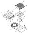
- the heat dissipating deviceincludes a base 10 for adsorbing heat generated by a heat generating member (not shown).
- a number of heat pipes 20are connected to the base 10 , and one end of each heat pipe 20 is inserted into a first heat sink 30 .
- the heat dissipating devicefurther includes a thermoelectric cooling module 40 mounted on the base 10 .
- a second heat sink 50is mounted on the thermoelectric cooling module 40 .
- a fan 60is disposed on the second heat sink 50 .
- the heat generated by the heat generating memberfirstly spreads to the base 10 , and the heat pipe 20 conducts the heat to the thermoelectric cooling module 40 . Finally, the heat reaches the first heat sink 30 and the second heat sink 50 , and the fan 60 dissipates the heat to the ambient atmosphere.
- the heat dissipating devicecan meet a general heat dissipating requirement of interface cards. However, the heat dissipating device also has some shortages.
- the thermoelectric cooling module 40because of the thermoelectric cooling module 40 is in direct contact with the base 10 , thus a temperature at a joint of the thermoelectric cooling module 40 and the base 10 is greatly less than a temperature of the heat pipe 20 . As a result, most of the heat generated by the heat generating member is conducted to the thermoelectric cooling module 40 . A heat dissipating ability of the heat pipe 20 is not fully used and a heat dissipating efficiency is very low.
- the thermoelectric cooling module 40is in contact with the heat generating member, therefore water generated by the thermoelectric cooling module 40 during a heat dissipating process may reaches to the heat generating member and finally cause a short circuit of the heat generating member.
- an objection of the present inventionis to provide a heat dissipating device that is capable of meeting different heat dissipating requirements in different conditions and has a high efficiency.
- a heat dissipation devicein one embodiment, includes a base, a first heat pipe, a first heat sink, a second heat pipe, a thermoelectric cooler and a second heat sink.
- the first heat pipeincludes a first end and a second end. The first end of the first heat pipe is connected to the base. The second end of the first heat pipe is connected to a bottom of the first heat sink.
- the second heat pipeincludes a first end and a second end. The first end of the second heat pipe is connected to the base. The second end of the second heat pipe is connected to a top end of the thermoelectric cooler.
- the second heat sinkis mounted on a bottom of the thermoelectric cooler and located at a side of the first heat sink.
- thermoelectric coolerspaces apart from the heat generating member. As such, the water generated by the thermoelectric cooler during a cooling process won't spread to the heat generating member and a short circuit of the heat generating member can be avoided.
- FIG. 1is an exploded perspective view of a conventional heat dissipating device
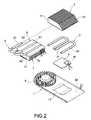
- FIG. 2is an exploded perspective view of a heat dissipating device in accordance an embodiment of the present invention
- FIG. 3is an assembled perspective view of the heat dissipating device of FIG. 2 ;
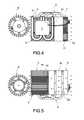
- FIG. 4is a top view showing an operation state of the heat dissipating device of FIG. 2 ;
- FIG. 5is a bottom view showing an operation state of the heat dissipating device of FIG. 2 ;
- FIG. 6is a flow chart of an operation procedure of a thermoelectric cooler in the heat dissipating device of FIG. 2 .
- FIGS. 2 and 3illustrate an exploded perspective view and an assembled perspective view of a heat dissipating device for mounting on a plate 1 in accordance with a first embodiment.
- the heat dissipating deviceincludes a base 2 .
- the base 2is a flat plate, and the base 2 is placed on a through groove 11 formed in the plate 1 .
- a surface of the base 2is in direct contact with a heat generating member (not shown) and another surface of the base 2 is attached to at least one first heat pipe 3 .
- the heat dissipating deviceincludes two first heat pipes 3 .
- the first heat pipe 3is flat and in “U” shape.
- a flat end surface of the first heat sink 3 that adjoins the base 2forms a substantial first end 31
- another opposite flat end surface of the first heat sink 3forms a second end 32 .
- the second end 32 of the first heat pipeis mounted on a first heat sink 4 , which includes a number of heat dissipating fins 41 .
- Each of the heat dissipating fins 41is spaced apart from adjacent heat dissipating fins 41 .
- Each two adjacent heat dissipating fins 41define an air flow passage 42 between thereof.
- a second heat pipe 5is also mounted on the base 2 .
- the heat dissipating deviceincludes two second heat pipes 5 .
- the second heat pipe 5includes a first end 51 and an opposite second end 52 .
- the first end 51is flat and is placed on the base 2 for adsorbing heat from the base 2 .
- the second end 52 of the second heat pipe 5is connected to a thermoelectric cooler 6 .
- a side of the thermoelectric cooler 6is connected to a first temperature sensor 91 and a second temperature sensor 92 using electrical wires.
- the first temperature sensor 91is mounted on the base 2 and the second temperature sensor 92 is mounted on a back side of the plate 1 .
- the first temperature sensor 91is configured for measuring a temperature of the base 2
- the second temperature sensor 92is configured for measuring a temperature of the working environment of the heat dissipating device.
- the thermoelectric cooler 6includes a first surface 61 and an opposite second surface 62 .
- the first surface 61is configured for absorbing heat from the second heat pipe 5 .
- the second surface 62is in contact with a second heat sink 7 .
- the second heat sink 7is disposed on the plate 1 and is adjacent to the first heat sink 4 .
- the second heat sink 7also includes a number of heat dissipating fins 71 .
- Each of the heat dissipating fins 71is spaced apart from adjacent heat dissipating fins 41 .
- Each two adjacent heat dissipating fins 41define an air flow passage 72 between thereof.
- the air flow passage 72is parallel to a respective air flow passage 42 .
- the heat dissipating devicefurther includes a fan 8 mounted on a side of the plate 1 .
- the fan 8blows an air flow along a direction that is parallel to the air flow passage 42 of the first heat sink 4 and the air flow passage 72 of the second heat sink 7 .
- the air flow generated by the fan 8can easily passes through the first heat sink 4 and the second heat sink 7 .
- FIGS. 4 and 5illustrate a top view and a bottom view of an operation procedure of the heat dissipating device respectively.
- the base 2adsorbs heat and transfers the heat to the first heat pipe 3 .
- the first heat pipe 3conducts the heat to the first heat sink 4 , and finally, the air flow generated by the fan 8 flows through the air flow passage 42 of the first heat sink 4 , carries the heat on surfaces of the heat dissipating fins 41 and spread it into outer atmosphere.
- the temperature of the heat generating member(not shown) is maintained at a low level.
- the second heat pipe 5efficiently adsorbs heat from the base 2 and transfers the heat from the first end 51 to the thermoelectric cooler 6 that is connected to the second 52 of the second heat pipe 5 .
- the first surface 61 of the thermoelectric cooler 6adsorbs heat from the second end 52 of the second heat pipe 5 and the thermoelectric cooler 6 efficiently transfers the heat to the second surface 62 .
- the heat at the second surface 62 of the thermoelectric cooler 6spreads to the second heat sink 7 and finally dissipates into ambient atmosphere by the heat dissipating fins 71 of the second heat sink 7 .
- the fan 8produces an air flow that flows through the air flow passage 72 of the second heat sink 7 , and carries heat off the heat dissipating fins 71 .
- a high heat dissipating efficiencycan be achieved by combining the first heat pipe 3 and the second heat pipe 7 .
- FIG. 6a controlling flow of the heat dissipating device is illustrated.
- step 100a temperature T 1 of the heat generating member is measured using the first temperature sensor.
- step 102a working temperature T 2 of the heat generating member is measured using the second temperature sensor.
- step 104an inner system of the thermoelectric cooler compares T 1 and T 2 .
- thermoelectric coolerstarts to work when T 1 is greater than T 2 , and then steps 100 to 104 are repeated.
- thermoelectric coolerstops when T 1 is less or equal to T 2 , and then the steps 100 to 104 are repeated.
Landscapes
- Engineering & Computer Science (AREA)
- Physics & Mathematics (AREA)
- General Engineering & Computer Science (AREA)
- Thermal Sciences (AREA)
- Mechanical Engineering (AREA)
- Condensed Matter Physics & Semiconductors (AREA)
- General Physics & Mathematics (AREA)
- Computer Hardware Design (AREA)
- Microelectronics & Electronic Packaging (AREA)
- Power Engineering (AREA)
- Sustainable Development (AREA)
- Life Sciences & Earth Sciences (AREA)
- Cooling Or The Like Of Electrical Apparatus (AREA)
- Cooling Or The Like Of Semiconductors Or Solid State Devices (AREA)
Abstract
Description
Claims (7)
Applications Claiming Priority (3)
| Application Number | Priority Date | Filing Date | Title |
|---|---|---|---|
| TW96217785U | 2007-10-24 | ||
| TW096217785 | 2007-10-24 | ||
| TW096217785UTWM331867U (en) | 2007-10-24 | 2007-10-24 | Heat dissipation device |
Publications (2)
| Publication Number | Publication Date |
|---|---|
| US20090109621A1 US20090109621A1 (en) | 2009-04-30 |
| US7852630B2true US7852630B2 (en) | 2010-12-14 |
Family
ID=40582521
Family Applications (1)
| Application Number | Title | Priority Date | Filing Date |
|---|---|---|---|
| US12/191,532Active2029-04-01US7852630B2 (en) | 2007-10-24 | 2008-08-14 | Heat dissipating device |
Country Status (2)
| Country | Link |
|---|---|
| US (1) | US7852630B2 (en) |
| TW (1) | TWM331867U (en) |
Cited By (7)
| Publication number | Priority date | Publication date | Assignee | Title |
|---|---|---|---|---|
| US20110180240A1 (en)* | 2010-01-23 | 2011-07-28 | Fu Zhun Precision Industry (Shen Zhen) Co., Ltd. | Centrifugal blower and heat dissipation device incorporating the same |
| US20110232877A1 (en)* | 2010-03-23 | 2011-09-29 | Celsia Technologies Taiwan, Inc. | Compact vapor chamber and heat-dissipating module having the same |
| US20130291564A1 (en)* | 2011-01-13 | 2013-11-07 | Sheetak, Inc. | Thermoelectric cooling systems |
| US20150070837A1 (en)* | 2013-09-09 | 2015-03-12 | Cooler Master Co., Ltd. | Heat-dissipating device for interface card |
| US10303228B2 (en)* | 2017-04-21 | 2019-05-28 | Evga Corporation | Multi-directional cooling structure for interface card |
| US11300333B2 (en)* | 2017-04-25 | 2022-04-12 | Lg Electronics Inc. | Cold water generation module for water treatment apparatus |
| US20220136778A1 (en)* | 2020-11-05 | 2022-05-05 | Vast Glory Electronics & Hardware & Plastic(Hui Zhou) Ltd. | Heat pipe and heat dissipation structure |
Families Citing this family (10)
| Publication number | Priority date | Publication date | Assignee | Title |
|---|---|---|---|---|
| CN103398494B (en)* | 2008-03-05 | 2017-03-01 | 史泰克公司 | Cooling system and the method for operation thermoelectric cooling system |
| US20110000224A1 (en)* | 2008-03-19 | 2011-01-06 | Uttam Ghoshal | Metal-core thermoelectric cooling and power generation device |
| IN2012DN01366A (en) | 2009-07-17 | 2015-06-05 | Sheetak Inc | |
| JP5647416B2 (en)* | 2010-01-12 | 2014-12-24 | 本田技研工業株式会社 | Heating element temperature estimation device |
| EP2807432A1 (en)* | 2011-11-17 | 2014-12-03 | Sheetak, Inc. | Method and apparatus for thermoelectric cooling of fluids |
| CN103543804A (en)* | 2012-07-13 | 2014-01-29 | 鸿富锦精密工业(深圳)有限公司 | Heat dissipation device |
| KR101509937B1 (en)* | 2013-10-11 | 2015-04-07 | 현대자동차주식회사 | Heat exchanger with thermoelectric element and method for producing the same |
| JP6079806B2 (en)* | 2015-03-23 | 2017-02-15 | 日本電気株式会社 | Cooling structure and apparatus |
| JP6667544B2 (en)* | 2015-10-08 | 2020-03-18 | 古河電気工業株式会社 | heatsink |
| TWI860545B (en)* | 2022-09-16 | 2024-11-01 | 奇鋐科技股份有限公司 | Thermal module |
Citations (4)
| Publication number | Priority date | Publication date | Assignee | Title |
|---|---|---|---|---|
| US6181556B1 (en)* | 1999-07-21 | 2001-01-30 | Richard K. Allman | Thermally-coupled heat dissipation apparatus for electronic devices |
| US20050174737A1 (en)* | 2001-12-30 | 2005-08-11 | Ronen Meir | Quiet cooling system for a computer |
| US20060164808A1 (en)* | 2005-01-21 | 2006-07-27 | Nvidia Corporation | Cooling system for computer hardware |
| US20090279251A1 (en)* | 2008-05-12 | 2009-11-12 | Fu Zhun Precision Industry (Shen Zhen) Co., Ltd. | Heat dissipation device with heat pipe |
- 2007
- 2007-10-24TWTW096217785Upatent/TWM331867U/ennot_activeIP Right Cessation
- 2008
- 2008-08-14USUS12/191,532patent/US7852630B2/enactiveActive
Patent Citations (4)
| Publication number | Priority date | Publication date | Assignee | Title |
|---|---|---|---|---|
| US6181556B1 (en)* | 1999-07-21 | 2001-01-30 | Richard K. Allman | Thermally-coupled heat dissipation apparatus for electronic devices |
| US20050174737A1 (en)* | 2001-12-30 | 2005-08-11 | Ronen Meir | Quiet cooling system for a computer |
| US20060164808A1 (en)* | 2005-01-21 | 2006-07-27 | Nvidia Corporation | Cooling system for computer hardware |
| US20090279251A1 (en)* | 2008-05-12 | 2009-11-12 | Fu Zhun Precision Industry (Shen Zhen) Co., Ltd. | Heat dissipation device with heat pipe |
Cited By (8)
| Publication number | Priority date | Publication date | Assignee | Title |
|---|---|---|---|---|
| US20110180240A1 (en)* | 2010-01-23 | 2011-07-28 | Fu Zhun Precision Industry (Shen Zhen) Co., Ltd. | Centrifugal blower and heat dissipation device incorporating the same |
| US20110232877A1 (en)* | 2010-03-23 | 2011-09-29 | Celsia Technologies Taiwan, Inc. | Compact vapor chamber and heat-dissipating module having the same |
| US20130291564A1 (en)* | 2011-01-13 | 2013-11-07 | Sheetak, Inc. | Thermoelectric cooling systems |
| US20150070837A1 (en)* | 2013-09-09 | 2015-03-12 | Cooler Master Co., Ltd. | Heat-dissipating device for interface card |
| US10303228B2 (en)* | 2017-04-21 | 2019-05-28 | Evga Corporation | Multi-directional cooling structure for interface card |
| US11300333B2 (en)* | 2017-04-25 | 2022-04-12 | Lg Electronics Inc. | Cold water generation module for water treatment apparatus |
| US20220136778A1 (en)* | 2020-11-05 | 2022-05-05 | Vast Glory Electronics & Hardware & Plastic(Hui Zhou) Ltd. | Heat pipe and heat dissipation structure |
| US11774180B2 (en)* | 2020-11-05 | 2023-10-03 | Vast Glory Electronics & Hardware & Plastic(Hui Zhou) Ltd. | Heat pipe and heat dissipation structure |
Also Published As
| Publication number | Publication date |
|---|---|
| TWM331867U (en) | 2008-05-01 |
| US20090109621A1 (en) | 2009-04-30 |
Similar Documents
| Publication | Publication Date | Title |
|---|---|---|
| US7852630B2 (en) | Heat dissipating device | |
| US7891411B2 (en) | Heat dissipation device having a fan for dissipating heat generated by at least two electronic components | |
| US8579016B2 (en) | Heat dissipation device with heat pipe | |
| US6860321B2 (en) | Heat-dissipating device | |
| US7613001B1 (en) | Heat dissipation device with heat pipe | |
| US20080247136A1 (en) | Heat dissipation apparatus for heat producing device | |
| US7806167B2 (en) | Heat dissipation device | |
| US7697293B1 (en) | Heat dissipation device | |
| US20070146990A1 (en) | Heat dissipating assembly | |
| US7363966B2 (en) | Heat dissipating device | |
| US20070195500A1 (en) | Heat dissipation apparatus | |
| US20080055854A1 (en) | Heat dissipation device | |
| US20080130228A1 (en) | Heat dissipation device | |
| US20070279867A1 (en) | Heat dissipating assembly of heat dissipating device | |
| US20090059604A1 (en) | Heat dissipation device for light emitting diode module | |
| US20080117597A1 (en) | Light emitting diode module having a thermal management element | |
| US7447027B2 (en) | Hybrid heat dissipation device | |
| US20080289799A1 (en) | Heat dissipation device with a heat pipe | |
| US6542370B1 (en) | Heat dissipating device for a CPU | |
| US20080190587A1 (en) | Heat-dissipating module | |
| US7753110B2 (en) | Heat dissipation device | |
| US6882532B2 (en) | Double-winged radiator for central processing unit | |
| US20090166006A1 (en) | Heat dissipation device | |
| US20060185821A1 (en) | Thermal dissipation device | |
| US7002795B2 (en) | Low noise heatsink |
Legal Events
| Date | Code | Title | Description |
|---|---|---|---|
| AS | Assignment | Owner name:COOLER MASTER CO., LTD, TAIWAN Free format text:ASSIGNMENT OF ASSIGNORS INTEREST;ASSIGNOR:CHENG, CHIA-CHUN;REEL/FRAME:021389/0978 Effective date:20080718 | |
| STCF | Information on status: patent grant | Free format text:PATENTED CASE | |
| FEPP | Fee payment procedure | Free format text:PAYOR NUMBER ASSIGNED (ORIGINAL EVENT CODE: ASPN); ENTITY STATUS OF PATENT OWNER: LARGE ENTITY | |
| AS | Assignment | Owner name:CHEMTRON RESEARCH LLC, DELAWARE Free format text:ASSIGNMENT OF ASSIGNORS INTEREST;ASSIGNOR:COOLER MASTER CO., LTD.;REEL/FRAME:027567/0332 Effective date:20111116 | |
| FPAY | Fee payment | Year of fee payment:4 | |
| MAFP | Maintenance fee payment | Free format text:PAYMENT OF MAINTENANCE FEE, 8TH YEAR, LARGE ENTITY (ORIGINAL EVENT CODE: M1552) Year of fee payment:8 | |
| MAFP | Maintenance fee payment | Free format text:PAYMENT OF MAINTENANCE FEE, 12TH YEAR, LARGE ENTITY (ORIGINAL EVENT CODE: M1553); ENTITY STATUS OF PATENT OWNER: LARGE ENTITY Year of fee payment:12 |