US7852233B2 - Driver notification system, device, and associated method - Google Patents
Driver notification system, device, and associated methodDownload PDFInfo
- Publication number
- US7852233B2 US7852233B2US11/771,718US77171807AUS7852233B2US 7852233 B2US7852233 B2US 7852233B2US 77171807 AUS77171807 AUS 77171807AUS 7852233 B2US7852233 B2US 7852233B2
- Authority
- US
- United States
- Prior art keywords
- hazard
- signals
- vehicle
- indication
- transmitter
- Prior art date
- Legal status (The legal status is an assumption and is not a legal conclusion. Google has not performed a legal analysis and makes no representation as to the accuracy of the status listed.)
- Expired - Fee Related, expires
Links
Images


Classifications
- G—PHYSICS
- G08—SIGNALLING
- G08G—TRAFFIC CONTROL SYSTEMS
- G08G1/00—Traffic control systems for road vehicles
- G08G1/09—Arrangements for giving variable traffic instructions
- G08G1/0962—Arrangements for giving variable traffic instructions having an indicator mounted inside the vehicle, e.g. giving voice messages
- G08G1/0967—Systems involving transmission of highway information, e.g. weather, speed limits
- G08G1/096766—Systems involving transmission of highway information, e.g. weather, speed limits where the system is characterised by the origin of the information transmission
- G08G1/096783—Systems involving transmission of highway information, e.g. weather, speed limits where the system is characterised by the origin of the information transmission where the origin of the information is a roadside individual element
Definitions
- FIG. 4Bis an illustration of a device carried by a traffic sign associated with a potential hazard according to another embodiment
- FIG. 4Dis an illustration of a device carried by a pedestrian according to another embodiment
- the transmission and reception of the activation signals 17 and hazard signals 18is performed wirelessly.
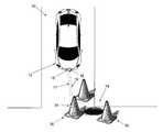
- the potential hazards 14may remain passive, or in a state in which the potential hazards 14 are not generating or transmitting hazard signals 18 , until the device associated with a particular potential hazard 14 receives an activation signal 17 , indicating the presence of a vehicle in the vicinity.
- the device associated with the potential hazard 14may generate hazard signals 18 to alert the vehicle of the potential hazard 14 .
- the vehicle transmitter 15may be transmitting activation signals 17 continuously as the vehicle is traveling.
- the transmitter 15may be powered by a mobile power source of the vehicle (not shown), such as an engine or battery.
Landscapes
- Life Sciences & Earth Sciences (AREA)
- Atmospheric Sciences (AREA)
- Physics & Mathematics (AREA)
- General Physics & Mathematics (AREA)
- Traffic Control Systems (AREA)
Abstract
Description
Claims (25)
Priority Applications (2)
| Application Number | Priority Date | Filing Date | Title |
|---|---|---|---|
| US11/771,718US7852233B2 (en) | 2007-06-29 | 2007-06-29 | Driver notification system, device, and associated method |
| US12/917,858US8436746B2 (en) | 2007-06-29 | 2010-11-02 | Driver notification system, device, and associated method |
Applications Claiming Priority (1)
| Application Number | Priority Date | Filing Date | Title |
|---|---|---|---|
| US11/771,718US7852233B2 (en) | 2007-06-29 | 2007-06-29 | Driver notification system, device, and associated method |
Related Child Applications (1)
| Application Number | Title | Priority Date | Filing Date |
|---|---|---|---|
| US12/917,858ContinuationUS8436746B2 (en) | 2007-06-29 | 2010-11-02 | Driver notification system, device, and associated method |
Publications (2)
| Publication Number | Publication Date |
|---|---|
| US20090002193A1 US20090002193A1 (en) | 2009-01-01 |
| US7852233B2true US7852233B2 (en) | 2010-12-14 |
Family
ID=40159733
Family Applications (2)
| Application Number | Title | Priority Date | Filing Date |
|---|---|---|---|
| US11/771,718Expired - Fee RelatedUS7852233B2 (en) | 2007-06-29 | 2007-06-29 | Driver notification system, device, and associated method |
| US12/917,858Expired - Fee RelatedUS8436746B2 (en) | 2007-06-29 | 2010-11-02 | Driver notification system, device, and associated method |
Family Applications After (1)
| Application Number | Title | Priority Date | Filing Date |
|---|---|---|---|
| US12/917,858Expired - Fee RelatedUS8436746B2 (en) | 2007-06-29 | 2010-11-02 | Driver notification system, device, and associated method |
Country Status (1)
| Country | Link |
|---|---|
| US (2) | US7852233B2 (en) |
Cited By (15)
| Publication number | Priority date | Publication date | Assignee | Title |
|---|---|---|---|---|
| US20100063648A1 (en)* | 2008-09-11 | 2010-03-11 | Noel Wayne Anderson | Distributed knowledge base program for vehicular localization and work-site management |
| US20100063626A1 (en)* | 2008-09-11 | 2010-03-11 | Noel Wayne Anderson | Distributed knowledge base for vehicular localization and work-site management |
| US20100063673A1 (en)* | 2008-09-11 | 2010-03-11 | Noel Wayne Anderson | Multi-vehicle high integrity perception |
| US20100063663A1 (en)* | 2008-09-11 | 2010-03-11 | Jonathan Louis Tolstedt | Leader-follower fully autonomous vehicle with operator on side |
| US20100194592A1 (en)* | 2009-02-04 | 2010-08-05 | Raymond Yim | Method and System for Disseminating Vehicle and Road Related Information in Multi-Hop Broadcast Networks |
| US8031085B1 (en)* | 2010-04-15 | 2011-10-04 | Deere & Company | Context-based sound generation |
| US8392065B2 (en) | 2008-09-11 | 2013-03-05 | Deere & Company | Leader-follower semi-autonomous vehicle with operator on side |
| DE102011118966A1 (en) | 2011-11-19 | 2013-05-23 | Valeo Schalter Und Sensoren Gmbh | Communication apparatus e.g. mobile telephone, for e.g. wirelessly transmitting data for e.g. motor car, has sensor for detecting velocity of apparatus that receives and analyzes data containing information about current speed road users |
| US8478493B2 (en) | 2008-09-11 | 2013-07-02 | Deere & Company | High integrity perception program |
| US8818567B2 (en) | 2008-09-11 | 2014-08-26 | Deere & Company | High integrity perception for machine localization and safeguarding |
| US8878660B2 (en) | 2011-06-28 | 2014-11-04 | Nissan North America, Inc. | Vehicle meter cluster |
| US8989972B2 (en) | 2008-09-11 | 2015-03-24 | Deere & Company | Leader-follower fully-autonomous vehicle with operator on side |
| US9026315B2 (en) | 2010-10-13 | 2015-05-05 | Deere & Company | Apparatus for machine coordination which maintains line-of-site contact |
| US9188980B2 (en) | 2008-09-11 | 2015-11-17 | Deere & Company | Vehicle with high integrity perception system |
| US9235214B2 (en) | 2008-09-11 | 2016-01-12 | Deere & Company | Distributed knowledge base method for vehicular localization and work-site management |
Families Citing this family (12)
| Publication number | Priority date | Publication date | Assignee | Title |
|---|---|---|---|---|
| US8525694B2 (en)* | 2010-12-21 | 2013-09-03 | Ford Global Technologies, Llc | Radio frequency identification object tracking |
| US8947219B2 (en) | 2011-04-22 | 2015-02-03 | Honda Motors Co., Ltd. | Warning system with heads up display |
| IL213373A (en) | 2011-06-05 | 2016-11-30 | Greenroad Driving Tech Ltd | Method and device for providing advanced warning to a vehicle driver |
| US9342989B2 (en)* | 2012-06-29 | 2016-05-17 | Bae Systems Information And Electronic Systems Integration Inc. | Radio-enabled collision avoidance system |
| DE102013005073A1 (en)* | 2013-03-22 | 2014-09-25 | Volkswagen Aktiengesellschaft | Method and warning device for securing a danger spot, especially in road traffic |
| US9141107B2 (en)* | 2013-04-10 | 2015-09-22 | Google Inc. | Mapping active and inactive construction zones for autonomous driving |
| US20150100189A1 (en)* | 2013-10-07 | 2015-04-09 | Ford Global Technologies, Llc | Vehicle-to-infrastructure communication |
| EP3257034B1 (en) | 2015-02-10 | 2020-04-08 | Ridar Systems LLC | Proximity awareness system for motor vehicles |
| US10933807B2 (en)* | 2018-11-28 | 2021-03-02 | International Business Machines Corporation | Visual hazard avoidance through an on-road projection system for vehicles |
| JP7318576B2 (en)* | 2020-03-18 | 2023-08-01 | トヨタ自動車株式会社 | Information processing device, information processing system, program, and vehicle |
| KR20230173724A (en)* | 2021-04-27 | 2023-12-27 | 모셔널 에이디 엘엘씨 | Improving ride comfort in various traffic scenarios for autonomous vehicles |
| US20220410802A1 (en)* | 2021-06-28 | 2022-12-29 | Sarah Aladas | System and method for aiding a person in locating vehicles and equipment |
Citations (8)
| Publication number | Priority date | Publication date | Assignee | Title |
|---|---|---|---|---|
| US3840868A (en)* | 1972-04-27 | 1974-10-08 | Vidar Labor Inc | Intrusion detecting apparatus |
| US5400045A (en)* | 1988-04-01 | 1995-03-21 | Yazaki Corporation | Indication display unit for a vehicle |
| US5515026A (en)* | 1994-01-28 | 1996-05-07 | Ewert; Roger D. | Total alert driver safety system |
| US5889475A (en)* | 1997-03-19 | 1999-03-30 | Klosinski; Stefan | Warning system for emergency vehicles |
| US6472978B1 (en)* | 2000-11-24 | 2002-10-29 | Yokogawa Electric Corporation | Traffic system to prevent from accidents |
| US20030020880A1 (en)* | 2000-07-27 | 2003-01-30 | Peter Knoll | Display device |
| US20040217869A1 (en)* | 2003-03-26 | 2004-11-04 | Michel Bouchard | Vehicle proximity alarm system and method |
| US20050073438A1 (en)* | 2003-09-23 | 2005-04-07 | Rodgers Charles E. | System and method for providing pedestrian alerts |
Family Cites Families (1)
| Publication number | Priority date | Publication date | Assignee | Title |
|---|---|---|---|---|
| US5506584A (en)* | 1995-02-15 | 1996-04-09 | Northrop Grumman Corporation | Radar sensor/processor for intelligent vehicle highway systems |
- 2007
- 2007-06-29USUS11/771,718patent/US7852233B2/ennot_activeExpired - Fee Related
- 2010
- 2010-11-02USUS12/917,858patent/US8436746B2/ennot_activeExpired - Fee Related
Patent Citations (8)
| Publication number | Priority date | Publication date | Assignee | Title |
|---|---|---|---|---|
| US3840868A (en)* | 1972-04-27 | 1974-10-08 | Vidar Labor Inc | Intrusion detecting apparatus |
| US5400045A (en)* | 1988-04-01 | 1995-03-21 | Yazaki Corporation | Indication display unit for a vehicle |
| US5515026A (en)* | 1994-01-28 | 1996-05-07 | Ewert; Roger D. | Total alert driver safety system |
| US5889475A (en)* | 1997-03-19 | 1999-03-30 | Klosinski; Stefan | Warning system for emergency vehicles |
| US20030020880A1 (en)* | 2000-07-27 | 2003-01-30 | Peter Knoll | Display device |
| US6472978B1 (en)* | 2000-11-24 | 2002-10-29 | Yokogawa Electric Corporation | Traffic system to prevent from accidents |
| US20040217869A1 (en)* | 2003-03-26 | 2004-11-04 | Michel Bouchard | Vehicle proximity alarm system and method |
| US20050073438A1 (en)* | 2003-09-23 | 2005-04-07 | Rodgers Charles E. | System and method for providing pedestrian alerts |
Cited By (24)
| Publication number | Priority date | Publication date | Assignee | Title |
|---|---|---|---|---|
| US8560145B2 (en) | 2008-09-11 | 2013-10-15 | Deere & Company | Distributed knowledge base program for vehicular localization and work-site management |
| US8195358B2 (en) | 2008-09-11 | 2012-06-05 | Deere & Company | Multi-vehicle high integrity perception |
| US20100063673A1 (en)* | 2008-09-11 | 2010-03-11 | Noel Wayne Anderson | Multi-vehicle high integrity perception |
| US20100063663A1 (en)* | 2008-09-11 | 2010-03-11 | Jonathan Louis Tolstedt | Leader-follower fully autonomous vehicle with operator on side |
| US9188980B2 (en) | 2008-09-11 | 2015-11-17 | Deere & Company | Vehicle with high integrity perception system |
| US8989972B2 (en) | 2008-09-11 | 2015-03-24 | Deere & Company | Leader-follower fully-autonomous vehicle with operator on side |
| US8392065B2 (en) | 2008-09-11 | 2013-03-05 | Deere & Company | Leader-follower semi-autonomous vehicle with operator on side |
| US8229618B2 (en) | 2008-09-11 | 2012-07-24 | Deere & Company | Leader-follower fully autonomous vehicle with operator on side |
| US8200428B2 (en) | 2008-09-11 | 2012-06-12 | Deere & Company | Multi-vehicle high integrity perception |
| US9274524B2 (en) | 2008-09-11 | 2016-03-01 | Deere & Company | Method for machine coordination which maintains line-of-site contact |
| US20100063626A1 (en)* | 2008-09-11 | 2010-03-11 | Noel Wayne Anderson | Distributed knowledge base for vehicular localization and work-site management |
| US8195342B2 (en) | 2008-09-11 | 2012-06-05 | Deere & Company | Distributed knowledge base for vehicular localization and work-site management |
| US9235214B2 (en) | 2008-09-11 | 2016-01-12 | Deere & Company | Distributed knowledge base method for vehicular localization and work-site management |
| US8467928B2 (en) | 2008-09-11 | 2013-06-18 | Deere & Company | Multi-vehicle high integrity perception |
| US8478493B2 (en) | 2008-09-11 | 2013-07-02 | Deere & Company | High integrity perception program |
| US8224500B2 (en) | 2008-09-11 | 2012-07-17 | Deere & Company | Distributed knowledge base program for vehicular localization and work-site management |
| US8666587B2 (en) | 2008-09-11 | 2014-03-04 | Deere & Company | Multi-vehicle high integrity perception |
| US8818567B2 (en) | 2008-09-11 | 2014-08-26 | Deere & Company | High integrity perception for machine localization and safeguarding |
| US20100063648A1 (en)* | 2008-09-11 | 2010-03-11 | Noel Wayne Anderson | Distributed knowledge base program for vehicular localization and work-site management |
| US20100194592A1 (en)* | 2009-02-04 | 2010-08-05 | Raymond Yim | Method and System for Disseminating Vehicle and Road Related Information in Multi-Hop Broadcast Networks |
| US8031085B1 (en)* | 2010-04-15 | 2011-10-04 | Deere & Company | Context-based sound generation |
| US9026315B2 (en) | 2010-10-13 | 2015-05-05 | Deere & Company | Apparatus for machine coordination which maintains line-of-site contact |
| US8878660B2 (en) | 2011-06-28 | 2014-11-04 | Nissan North America, Inc. | Vehicle meter cluster |
| DE102011118966A1 (en) | 2011-11-19 | 2013-05-23 | Valeo Schalter Und Sensoren Gmbh | Communication apparatus e.g. mobile telephone, for e.g. wirelessly transmitting data for e.g. motor car, has sensor for detecting velocity of apparatus that receives and analyzes data containing information about current speed road users |
Also Published As
| Publication number | Publication date |
|---|---|
| US8436746B2 (en) | 2013-05-07 |
| US20090002193A1 (en) | 2009-01-01 |
| US20110043376A1 (en) | 2011-02-24 |
Similar Documents
| Publication | Publication Date | Title |
|---|---|---|
| US7852233B2 (en) | Driver notification system, device, and associated method | |
| US8669857B2 (en) | Hand-held device integration for automobile safety | |
| US9677893B2 (en) | Vehicular navigation system updating based on object presence/absence | |
| US7099774B2 (en) | GPS based vehicle warning and location system | |
| US7042345B2 (en) | Intelligent vehicle apparatus and method for using the apparatus | |
| US20180286232A1 (en) | Traffic control using sound signals | |
| US20070005245A1 (en) | Biometric apparatus and method | |
| CN108307295A (en) | The method and apparatus for avoiding accident for vulnerable road user | |
| JP2009531766A (en) | Warning device and method | |
| US20050035878A1 (en) | Early warning system for approaching emergency vehicle | |
| KR20190101909A (en) | Viechle radar system for sensing danger | |
| KR20140034724A (en) | Hazard warning system for vehicles | |
| JP2002123896A (en) | Vehicle collision warning device | |
| US20090005988A1 (en) | Vehicle pursuit caution light | |
| JP6799984B2 (en) | Road-to-vehicle information communication system | |
| US20040155795A1 (en) | Systems and methods for motor vehicle-based emergency/hazard detection | |
| KR101855301B1 (en) | Vehicle entry alarm system in traffic-walking dangerous zone and its operating method | |
| KR102262879B1 (en) | Blind spot detection and notification method according to the driving path characteristics of the vehicle | |
| CN104412312A (en) | Communication device and communication method for vehicle | |
| US20020175829A1 (en) | System and method for warning of an upcoming precautionary zone | |
| JP2005200001A (en) | Safe restraint system and method based on navigation | |
| JP5458315B2 (en) | Vehicle alarm device | |
| US20180372864A1 (en) | Method for Broadcasting a User's Location to Vehicle Operators Using Wireless Communication | |
| JP2010065402A (en) | Safety system for road and alarm method | |
| KR101874123B1 (en) | Vehicle and portable terminal for communicating with the vehicle |
Legal Events
| Date | Code | Title | Description |
|---|---|---|---|
| AS | Assignment | Owner name:MCI COMMUNICATIONS SERVICES, INC., VIRGINIA Free format text:ASSIGNMENT OF ASSIGNORS INTEREST;ASSIGNOR:CEMPER, KIRK E.;REEL/FRAME:019513/0476 Effective date:20070629 | |
| AS | Assignment | Owner name:VERIZON PATENT AND LICENSING INC., NEW JERSEY Free format text:ASSIGNMENT OF ASSIGNORS INTEREST;ASSIGNOR:MCI COMMUNICATIONS SERVICES, INC.;REEL/FRAME:023250/0376 Effective date:20090801 Owner name:VERIZON PATENT AND LICENSING INC.,NEW JERSEY Free format text:ASSIGNMENT OF ASSIGNORS INTEREST;ASSIGNOR:MCI COMMUNICATIONS SERVICES, INC.;REEL/FRAME:023250/0376 Effective date:20090801 | |
| STCF | Information on status: patent grant | Free format text:PATENTED CASE | |
| FPAY | Fee payment | Year of fee payment:4 | |
| MAFP | Maintenance fee payment | Free format text:PAYMENT OF MAINTENANCE FEE, 8TH YEAR, LARGE ENTITY (ORIGINAL EVENT CODE: M1552) Year of fee payment:8 | |
| FEPP | Fee payment procedure | Free format text:MAINTENANCE FEE REMINDER MAILED (ORIGINAL EVENT CODE: REM.); ENTITY STATUS OF PATENT OWNER: LARGE ENTITY | |
| LAPS | Lapse for failure to pay maintenance fees | Free format text:PATENT EXPIRED FOR FAILURE TO PAY MAINTENANCE FEES (ORIGINAL EVENT CODE: EXP.); ENTITY STATUS OF PATENT OWNER: LARGE ENTITY | |
| STCH | Information on status: patent discontinuation | Free format text:PATENT EXPIRED DUE TO NONPAYMENT OF MAINTENANCE FEES UNDER 37 CFR 1.362 | |
| FP | Lapsed due to failure to pay maintenance fee | Effective date:20221214 |