US7852170B2 - Adaptive impedance matching apparatus, system and method with improved dynamic range - Google Patents
Adaptive impedance matching apparatus, system and method with improved dynamic rangeDownload PDFInfo
- Publication number
- US7852170B2 US7852170B2US12/287,599US28759908AUS7852170B2US 7852170 B2US7852170 B2US 7852170B2US 28759908 AUS28759908 AUS 28759908AUS 7852170 B2US7852170 B2US 7852170B2
- Authority
- US
- United States
- Prior art keywords
- voltage
- variable
- output port
- capacitors
- matching network
- Prior art date
- Legal status (The legal status is an assumption and is not a legal conclusion. Google has not performed a legal analysis and makes no representation as to the accuracy of the status listed.)
- Active
Links
- 238000000034methodMethods0.000titleclaimsdescription23
- 230000003044adaptive effectEffects0.000titleclaimsdescription11
- 230000005405multipoleEffects0.000claimsabstractdescription4
- 239000003990capacitorSubstances0.000claimsdescription40
- 230000008878couplingEffects0.000claimsdescription11
- 238000010168coupling processMethods0.000claimsdescription11
- 238000005859coupling reactionMethods0.000claimsdescription11
- 239000004065semiconductorSubstances0.000claimsdescription7
- 238000010079rubber tappingMethods0.000claimsdescription6
- 230000015654memoryEffects0.000description15
- 229910044991metal oxideInorganic materials0.000description15
- 150000004706metal oxidesChemical class0.000description15
- 239000002131composite materialSubstances0.000description12
- 239000003989dielectric materialSubstances0.000description12
- 239000000463materialSubstances0.000description12
- -1BaCaZrTiO3Inorganic materials0.000description11
- 239000000395magnesium oxideSubstances0.000description11
- CPLXHLVBOLITMK-UHFFFAOYSA-Nmagnesium oxideInorganic materials[Mg]=OCPLXHLVBOLITMK-UHFFFAOYSA-N0.000description11
- 229910052454barium strontium titanateInorganic materials0.000description10
- AXZKOIWUVFPNLO-UHFFFAOYSA-Nmagnesium;oxygen(2-)Chemical compound[O-2].[Mg+2]AXZKOIWUVFPNLO-UHFFFAOYSA-N0.000description10
- 229910052751metalInorganic materials0.000description9
- 239000002184metalSubstances0.000description9
- 229910052914metal silicateInorganic materials0.000description9
- 150000002739metalsChemical class0.000description9
- 229910052839forsteriteInorganic materials0.000description8
- 230000006870functionEffects0.000description8
- 239000011777magnesiumSubstances0.000description8
- 239000011575calciumSubstances0.000description6
- 239000000919ceramicSubstances0.000description6
- 229910002971CaTiO3Inorganic materials0.000description5
- 229910017676MgTiO3Inorganic materials0.000description5
- 229910052791calciumInorganic materials0.000description5
- 229910052744lithiumInorganic materials0.000description5
- 229910052749magnesiumInorganic materials0.000description5
- 239000000203mixtureSubstances0.000description5
- 238000012545processingMethods0.000description5
- 239000000654additiveSubstances0.000description4
- 229910052788bariumInorganic materials0.000description4
- WMWLMWRWZQELOS-UHFFFAOYSA-Nbismuth(iii) oxideChemical compoundO=[Bi]O[Bi]=OWMWLMWRWZQELOS-UHFFFAOYSA-N0.000description4
- 239000000872bufferSubstances0.000description4
- 150000001875compoundsChemical class0.000description4
- 230000006872improvementEffects0.000description4
- TWNQGVIAIRXVLR-UHFFFAOYSA-Noxo(oxoalumanyloxy)alumaneChemical compoundO=[Al]O[Al]=OTWNQGVIAIRXVLR-UHFFFAOYSA-N0.000description4
- 230000000737periodic effectEffects0.000description4
- 229910052700potassiumInorganic materials0.000description4
- 229910052708sodiumInorganic materials0.000description4
- 239000011734sodiumSubstances0.000description4
- 229910052712strontiumInorganic materials0.000description4
- 229910052882wollastoniteInorganic materials0.000description4
- 229910026161MgAl2O4Inorganic materials0.000description3
- 229910003383SrSiO3Inorganic materials0.000description3
- 230000005540biological transmissionEffects0.000description3
- 230000001413cellular effectEffects0.000description3
- 238000010586diagramMethods0.000description3
- 239000010408filmSubstances0.000description3
- 229910052748manganeseInorganic materials0.000description3
- 239000011572manganeseSubstances0.000description3
- 238000004519manufacturing processMethods0.000description3
- 230000003287optical effectEffects0.000description3
- 150000004760silicatesChemical class0.000description3
- 229910052596spinelInorganic materials0.000description3
- 239000010409thin filmSubstances0.000description3
- 238000012546transferMethods0.000description3
- 229910015846BaxSr1-xTiO3Inorganic materials0.000description2
- 229910004774CaSnO3Inorganic materials0.000description2
- 229910002976CaZrO3Inorganic materials0.000description2
- PWHULOQIROXLJO-UHFFFAOYSA-NManganeseChemical compound[Mn]PWHULOQIROXLJO-UHFFFAOYSA-N0.000description2
- VYPSYNLAJGMNEJ-UHFFFAOYSA-NSilicium dioxideChemical compoundO=[Si]=OVYPSYNLAJGMNEJ-UHFFFAOYSA-N0.000description2
- 229910002370SrTiO3Inorganic materials0.000description2
- 229910010252TiO3Inorganic materials0.000description2
- 150000004645aluminatesChemical class0.000description2
- 229910052782aluminiumInorganic materials0.000description2
- 230000008901benefitEffects0.000description2
- 229910052790berylliumInorganic materials0.000description2
- 229910052792caesiumInorganic materials0.000description2
- 229910010293ceramic materialInorganic materials0.000description2
- 230000008859changeEffects0.000description2
- 239000000470constituentSubstances0.000description2
- 238000013461designMethods0.000description2
- 238000005516engineering processMethods0.000description2
- 229910052730franciumInorganic materials0.000description2
- MRELNEQAGSRDBK-UHFFFAOYSA-Nlanthanum oxideInorganic materials[O-2].[O-2].[O-2].[La+3].[La+3]MRELNEQAGSRDBK-UHFFFAOYSA-N0.000description2
- NUJOXMJBOLGQSY-UHFFFAOYSA-Nmanganese dioxideChemical compoundO=[Mn]=ONUJOXMJBOLGQSY-UHFFFAOYSA-N0.000description2
- KTUFCUMIWABKDW-UHFFFAOYSA-Noxo(oxolanthaniooxy)lanthanumChemical compoundO=[La]O[La]=OKTUFCUMIWABKDW-UHFFFAOYSA-N0.000description2
- RVTZCBVAJQQJTK-UHFFFAOYSA-Noxygen(2-);zirconium(4+)Chemical compound[O-2].[O-2].[Zr+4]RVTZCBVAJQQJTK-UHFFFAOYSA-N0.000description2
- 230000008569processEffects0.000description2
- 229910052705radiumInorganic materials0.000description2
- 229910001404rare earth metal oxideInorganic materials0.000description2
- 229910052701rubidiumInorganic materials0.000description2
- 229910052710siliconInorganic materials0.000description2
- VWDWKYIASSYTQR-UHFFFAOYSA-Nsodium nitrateChemical compound[Na+].[O-][N+]([O-])=OVWDWKYIASSYTQR-UHFFFAOYSA-N0.000description2
- 229910052719titaniumInorganic materials0.000description2
- 229910052721tungstenInorganic materials0.000description2
- 229910052726zirconiumInorganic materials0.000description2
- 229910001928zirconium oxideInorganic materials0.000description2
- 229910002929BaSnO3Inorganic materials0.000description1
- 229910004829CaWO4Inorganic materials0.000description1
- 229910052684CeriumInorganic materials0.000description1
- XEEYBQQBJWHFJM-UHFFFAOYSA-NIronChemical compound[Fe]XEEYBQQBJWHFJM-UHFFFAOYSA-N0.000description1
- 229910003334KNbO3Inorganic materials0.000description1
- 229910007562Li2SiO3Inorganic materials0.000description1
- 229910003327LiNbO3Inorganic materials0.000description1
- 229910012463LiTaO3Inorganic materials0.000description1
- WHXSMMKQMYFTQS-UHFFFAOYSA-NLithiumChemical compound[Li]WHXSMMKQMYFTQS-UHFFFAOYSA-N0.000description1
- 229910052779NeodymiumInorganic materials0.000description1
- 229910003781PbTiO3Inorganic materials0.000description1
- 229910052777PraseodymiumInorganic materials0.000description1
- 108010001267Protein SubunitsProteins0.000description1
- 239000004115Sodium SilicateSubstances0.000description1
- 229910004481Ta2O3Inorganic materials0.000description1
- 229920002253TannatePolymers0.000description1
- RTAQQCXQSZGOHL-UHFFFAOYSA-NTitaniumChemical compound[Ti]RTAQQCXQSZGOHL-UHFFFAOYSA-N0.000description1
- MCMNRKCIXSYSNV-UHFFFAOYSA-NZrO2Inorganic materialsO=[Zr]=OMCMNRKCIXSYSNV-UHFFFAOYSA-N0.000description1
- AZJLMWQBMKNUKB-UHFFFAOYSA-N[Zr].[La]Chemical compound[Zr].[La]AZJLMWQBMKNUKB-UHFFFAOYSA-N0.000description1
- 238000010521absorption reactionMethods0.000description1
- 230000009471actionEffects0.000description1
- 230000000996additive effectEffects0.000description1
- 229910052656albiteInorganic materials0.000description1
- 229910000287alkaline earth metal oxideInorganic materials0.000description1
- 229910052661anorthiteInorganic materials0.000description1
- 229910021523barium zirconateInorganic materials0.000description1
- 229910052797bismuthInorganic materials0.000description1
- BRPQOXSCLDDYGP-UHFFFAOYSA-Ncalcium oxideChemical compound[O-2].[Ca+2]BRPQOXSCLDDYGP-UHFFFAOYSA-N0.000description1
- 239000000292calcium oxideSubstances0.000description1
- ODINCKMPIJJUCX-UHFFFAOYSA-Ncalcium oxideInorganic materials[Ca]=OODINCKMPIJJUCX-UHFFFAOYSA-N0.000description1
- 229910052804chromiumInorganic materials0.000description1
- 229910052681coesiteInorganic materials0.000description1
- 238000004891communicationMethods0.000description1
- 229910052906cristobaliteInorganic materials0.000description1
- 230000001934delayEffects0.000description1
- 229920005994diacetyl cellulosePolymers0.000description1
- 229910052637diopsideInorganic materials0.000description1
- 230000000694effectsEffects0.000description1
- 230000005684electric fieldEffects0.000description1
- 230000002708enhancing effectEffects0.000description1
- 229910000174eucryptiteInorganic materials0.000description1
- 230000002349favourable effectEffects0.000description1
- 239000011521glassSubstances0.000description1
- 229910052735hafniumInorganic materials0.000description1
- JYTUFVYWTIKZGR-UHFFFAOYSA-Nholmium oxideInorganic materials[O][Ho]O[Ho][O]JYTUFVYWTIKZGR-UHFFFAOYSA-N0.000description1
- 229910052909inorganic silicateInorganic materials0.000description1
- 229910052746lanthanumInorganic materials0.000description1
- 229910052745leadInorganic materials0.000description1
- HTUMBQDCCIXGCV-UHFFFAOYSA-Nlead oxideChemical compound[O-2].[Pb+2]HTUMBQDCCIXGCV-UHFFFAOYSA-N0.000description1
- YEXPOXQUZXUXJW-UHFFFAOYSA-Nlead(II) oxideInorganic materials[Pb]=OYEXPOXQUZXUXJW-UHFFFAOYSA-N0.000description1
- 230000007774longtermEffects0.000description1
- 238000013507mappingMethods0.000description1
- 238000012986modificationMethods0.000description1
- 230000004048modificationEffects0.000description1
- 229910052750molybdenumInorganic materials0.000description1
- PLDDOISOJJCEMH-UHFFFAOYSA-Nneodymium oxideInorganic materials[O-2].[O-2].[O-2].[Nd+3].[Nd+3]PLDDOISOJJCEMH-UHFFFAOYSA-N0.000description1
- 229910052758niobiumInorganic materials0.000description1
- 230000010363phase shiftEffects0.000description1
- 230000000135prohibitive effectEffects0.000description1
- 229910052761rare earth metalInorganic materials0.000description1
- 150000002910rare earth metalsChemical class0.000description1
- 230000009467reductionEffects0.000description1
- 239000003870refractory metalSubstances0.000description1
- 229910052706scandiumInorganic materials0.000description1
- 239000000377silicon dioxideSubstances0.000description1
- 229910052911sodium silicateInorganic materials0.000description1
- 235000019351sodium silicatesNutrition0.000description1
- 125000005402stannate groupChemical group0.000description1
- 230000003068static effectEffects0.000description1
- 229910052682stishoviteInorganic materials0.000description1
- 229910014031strontium zirconium oxideInorganic materials0.000description1
- 239000000126substanceSubstances0.000description1
- 229910052715tantalumInorganic materials0.000description1
- 229910052718tinInorganic materials0.000description1
- 230000009466transformationEffects0.000description1
- 229910052723transition metalInorganic materials0.000description1
- 229910000314transition metal oxideInorganic materials0.000description1
- 150000003624transition metalsChemical class0.000description1
- 238000013519translationMethods0.000description1
- 229910052905tridymiteInorganic materials0.000description1
- WFKWXMTUELFFGS-UHFFFAOYSA-NtungstenChemical compound[W]WFKWXMTUELFFGS-UHFFFAOYSA-N0.000description1
- 239000010937tungstenSubstances0.000description1
- 229910052720vanadiumInorganic materials0.000description1
- 230000000007visual effectEffects0.000description1
- 229910052844willemiteInorganic materials0.000description1
- FIXNOXLJNSSSLJ-UHFFFAOYSA-Nytterbium(III) oxideInorganic materialsO=[Yb]O[Yb]=OFIXNOXLJNSSSLJ-UHFFFAOYSA-N0.000description1
- 229910052727yttriumInorganic materials0.000description1
- 229910052845zirconInorganic materials0.000description1
Images


Classifications
- H—ELECTRICITY
- H04—ELECTRIC COMMUNICATION TECHNIQUE
- H04B—TRANSMISSION
- H04B1/00—Details of transmission systems, not covered by a single one of groups H04B3/00 - H04B13/00; Details of transmission systems not characterised by the medium used for transmission
- H04B1/02—Transmitters
- H04B1/04—Circuits
- H04B1/0458—Arrangements for matching and coupling between power amplifier and antenna or between amplifying stages
- H—ELECTRICITY
- H01—ELECTRIC ELEMENTS
- H01Q—ANTENNAS, i.e. RADIO AERIALS
- H01Q1/00—Details of, or arrangements associated with, antennas
- H01Q1/12—Supports; Mounting means
- H01Q1/22—Supports; Mounting means by structural association with other equipment or articles
- H01Q1/24—Supports; Mounting means by structural association with other equipment or articles with receiving set
- H01Q1/241—Supports; Mounting means by structural association with other equipment or articles with receiving set used in mobile communications, e.g. GSM
- H01Q1/242—Supports; Mounting means by structural association with other equipment or articles with receiving set used in mobile communications, e.g. GSM specially adapted for hand-held use
- H01Q1/243—Supports; Mounting means by structural association with other equipment or articles with receiving set used in mobile communications, e.g. GSM specially adapted for hand-held use with built-in antennas
- H—ELECTRICITY
- H01—ELECTRIC ELEMENTS
- H01Q—ANTENNAS, i.e. RADIO AERIALS
- H01Q1/00—Details of, or arrangements associated with, antennas
- H01Q1/50—Structural association of antennas with earthing switches, lead-in devices or lightning protectors
- H—ELECTRICITY
- H03—ELECTRONIC CIRCUITRY
- H03H—IMPEDANCE NETWORKS, e.g. RESONANT CIRCUITS; RESONATORS
- H03H7/00—Multiple-port networks comprising only passive electrical elements as network components
- H03H7/38—Impedance-matching networks
- H03H7/40—Automatic matching of load impedance to source impedance
- H—ELECTRICITY
- H03—ELECTRONIC CIRCUITRY
- H03H—IMPEDANCE NETWORKS, e.g. RESONANT CIRCUITS; RESONATORS
- H03H7/00—Multiple-port networks comprising only passive electrical elements as network components
- H03H7/38—Impedance-matching networks
- H03H2007/386—Multiple band impedance matching
Definitions
- an adaptive impedance matching moduleis to adaptively maximize the RF power transfer from its input port to an arbitrary load impedance ZL that changes as a function of time.
- An embodiment of the present inventionprovides an apparatus, comprising an RF matching network connected to at least one RF input port and at least one RF output port and including one or more voltage or current controlled variable reactive elements, a voltage detector connected to the at least one RF output port via a variable voltage divider to determine the voltage at the at least one RF output port and provide voltage information to a controller that controls a bias driving circuit which provides bias voltage or bias current to the RF matching network, and wherein the RF matching network is adapted to maximize RF power transferred from the at least one RF input port to the at least one RF output port by varying the voltage or current to the voltage or current controlled variable reactive elements to maximize the RF voltage at the at least one RF output port.
- the voltage detectormay be a diode detector and wherein the variable voltage divider connected to the voltage detector may be adapted to improve the dynamic range of the apparatus.
- a loop controllermay be associated with the variable voltage divider to make the variable voltage divider programmable and the variable voltage divider may be implemented using a multi-pole RF switch to select one of a plurality of different resistances.
- the variable voltage dividermay be operable to allow a detector coupled to the output port to be more isolated at higher power levels and improve linearity of the module for high signal levels.
- the RF output nodemay be connected to a shunt RF branch comprising a series string of capacitors and by selectively tapping into various circuit nodes along the string, a variable output voltage divider is obtained.
- tapping into various circuit nodesmay be accomplished using a digitally controlled RF switch and the RF switch may be selected from the group consisting of: FETs, MEMS or PIN diodes.
- a method of adaptive impedance matchingcomprising connecting an RF matching network to at least one RF input port and at least one RF output port and including one or more voltage or current controlled variable reactive elements, using a voltage detector connected to the at least one RF output port via a variable voltage divider to determine the voltage at the at least one RF output port and providing the voltage information to a controller that controls a bias driving circuit which provides bias voltage or bias current to the RF matching network, and adapting the RF matching network to maximize RF power transferred from the at least one RF input port to the at least one RF output port by varying the voltage or current to the voltage or current controlled variable reactive elements to maximize the RF voltage at the at least one RF output port.
- a machine-accessible mediumthat provides instructions, which when accessed, cause a machine to perform operations comprising connecting an RF matching network to at least one RF input port and at least one RF output port and including one or more voltage or current controlled variable reactive elements, using a voltage detector connected to the at least one RF output port via a variable voltage divider to determine the voltage at the at least one RF output port and providing the voltage information to a controller that controls a bias driving circuit which provides voltage or current bias to the RF matching network, and adapting the RF matching network to maximize RF power transferred from the at least one RF input port to the at least one RF output port by varying the voltage or current to the voltage or current controlled variable reactive elements to maximize the RF voltage at the at least one RF output port.
- FIG. 1illustrates a block diagram of an adaptive impedance matching module AIMM control system of one embodiment of the present invention
- FIG. 2illustrates a control system for a multi-port adaptive impedance matching module of one embodiment of the present invention
- FIG. 3shows an implementation of an AIMM closed loop control system of one embodiment of the present invention
- FIG. 4is a block diagram of an adaptive impedance matching module (AIMM) with a variable voltage divider for improved dynamic range of one embodiment of the present invention
- FIG. 5illustrates an embodiment of an enhanced dynamic range AIMM control system
- FIG. 6shows a second embodiment of an enhanced dynamic range AIMM control system.
- An algorithmis here, and generally, considered to be a self-consistent sequence of acts or operations leading to a desired result. These include physical manipulations of physical quantities. Usually, though not necessarily, these quantities take the form of electrical or magnetic signals capable of being stored, transferred, combined, compared, and otherwise manipulated. It has proven convenient at times, principally for reasons of common usage, to refer to these signals as bits, values, elements, symbols, characters, terms, numbers or the like. It should be understood, however, that all of these and similar terms are to be associated with the appropriate physical quantities and are merely convenient labels applied to these quantities.
- Embodiments of the present inventionmay include apparatuses for performing the operations herein.
- An apparatusmay be specially constructed for the desired purposes, or it may comprise a general purpose computing device selectively activated or reconfigured by a program stored in the device.
- a programmay be stored on a storage medium, such as, but not limited to, any type of disk including floppy disks, optical disks, compact disc read only memories (CD-ROMs), magnetic-optical disks, read-only memories (ROMs), random access memories (RAMs), electrically programmable read-only memories (EPROMs), electrically erasable and programmable read only memories (EEPROMs), magnetic or optical cards, or any other type of media suitable for storing electronic instructions, and capable of being coupled to a system bus for a computing device.
- a storage mediumsuch as, but not limited to, any type of disk including floppy disks, optical disks, compact disc read only memories (CD-ROMs), magnetic-optical disks, read-only memories (ROMs), random access memories (
- Coupledmay be used to indicate that two or more elements are in direct physical or electrical contact with each other.
- Connectedmay be used to indicate that two or more elements are in direct physical or electrical contact with each other.
- Connectedmay be used to indicate that two or more elements are in either direct or indirect (with other intervening elements between them) physical or electrical contact with each other, and/or that the two or more elements co-operate or interact with each other (e.g. as in a cause an effect relationship).
- An embodiment of the present inventionprovides closed-loop control of an adaptive impedance matching module (AIMM).
- the RF output node voltage of the AIMM tuner circuitmay be monitored and maximized to insure the best available impedance match to arbitrary load impedance.
- improvement in dynamic rangemay be achieved by adaptively changing the RF coupling level between the voltage sensed at the output port (antenna side) of the matching network and the voltage provided to the detector.
- This coupling levelmay be controlled by a processor which also does the closed loop tuning.
- a simple voltage dividercomprised of resistors and a digitally controlled RF switch may be used to realize variable coupling levels, although the present invention is not limited in this respect.
- Another means of realizing variable coupling levelsis to digitally switch between different tap points in a series string of variables capacitors which form a shunt voltage tunable dielectric capacitor at the output node of the AIMM tuner.
- FIG. 1shown generally as 100 , is an AIMM block diagram.
- the RF matching network 110may contain inductors and capacitors required to transform the arbitrary load impedance Z L 135 to an impedance equal to or close to a defined system impedance, such as 50 ohms.
- the net benefit of this transformationis an improvement in the level of power transferred to the load Z L 135 , and a reduction in the level of reflected power from the RF input port 105 .
- This second benefitis also known as an improvement in the input mismatch loss where mismatch loss is defined as (1 ⁇
- the RF matching network 110may contain one or more variable reactive elements which are voltage controlled.
- the variable reactive elementsmay be, although are not required to be, variable capacitances, variable inductances, or both.
- the variable capacitorsmay be semiconductor varactors, MEMS varactors, MEMS switched capacitors, ferroelectric capacitors, or any other technology that implements a variable capacitance.
- the variable inductorsmay be switched inductors using various types of RF switches including MEMS-based switches.
- the reactive elementsmay be current controlled rather than voltage controlled without departing from the spirit and scope of the present invention.
- variable capacitors of the RF matching networkmay be tunable integrated circuits, such as voltage tunable dielectric capacitors or Parascan Tunable Capacitors (PTCs).
- PTCsParascan Tunable Capacitors
- Each tunable capacitormay be realized as a series network of capacitors which are all tuned using a common tuning voltage.
- the RF voltage detector 130 of FIG. 1may be used to monitor the magnitude of the output nodal voltage.
- the fundamental concept used in this control systemis that the RF power transferred to the arbitrary load impedance 135 is maximized when the RF voltage magnitude at the output port 115 is maximized. It is the understanding of this concept that allows one to remove the directional coupler conventionally located in series with the input port and to thus simplifying the architecture of the control system. A directional coupler is undesirable for numerous reasons:
- the RF voltage detector 130may be comprised of a diode detector, a temperature compensated diode detector, a logarithmic amplifier, or any other means to detect an RF voltage magnitude. The phase of the RF voltage is not required.
- the controller 125accepts as an input the information associated with the detected RF output 115 voltage. The controller 125 provides one or more outputs that control the bias voltage driver circuits.
- the controller 125may be digitally-based such as a microprocessor, a digital signal processor, or an ASIC, or any other digital state machine. The controller may also be an analog-based system.
- the bias voltage driver circuit 120is a means of mapping control signals that are output from the controller 125 to a voltage range that is compatible with the tunable reactive elements in the RF matching network 110 .
- the driver circuitmay be an application specific integrated circuit (ASIC) whose function is to accept digital signals from the controller 125 and then output one or more analog voltages for one or more tunable reactive elements in the RF matching circuit 110 .
- ASICapplication specific integrated circuit
- the driver circuit 120may provide a wider range of analog tuning voltages than what is used as a power supply voltage by the controller 125 . Hence the driver circuit 120 may perform the functions of voltage translation and voltage scaling.
- the purpose of the control system shown in FIG. 1is to monitor the output RF voltage magnitude and to use this information as an input to an algorithm that adjusts the tuning voltages provided to the tunable reactive elements in the RF matching network 110 .
- the algorithmadjusts the reactances to maximize the RF output 115 voltage.
- the algorithmmay be a scalar multi-dimensional maximization algorithm where the independent variables are the tuning voltages for the reactive elements.
- Some embodiments of the operation of the tuning algorithm of the present inventionmay increase performance of a network and/or enable it to perform in systems that might otherwise make it difficult for the system to make all the required system specifications.
- GSM, EDGE and WCDMA systemshave specification limiting the allowable phase shifts within a transmit burst.
- TRPtotal radiated power
- the AIMM tuning algorithmcan contain the following attributes: 1—Limit the number of tuning “steps” that are taken within a transmit burst, or limit the steps to only be allowed between bursts (when the transmitter is disabled). This can be accomplished easily by putting time delays in the algorithm, or to only allow tuning when a Tx Enable line in the transmitter is low.
- the simplified control system shown in FIG. 1is illustrated using a 2 port RF matching network.
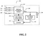
- this control systemis extensible to multi-port RF matching networks as shown in FIG. 2 , generally as 200 .
- N transmittersdrive the N input ports 205 , 210 , 215 and 220 , and that each input port is coupled to the single RF output port 240 using RF circuits that contain variable reactive elements.
- the objective of the control systemremains the same, to maximize the RF output voltage magnitude, and thus to optimize the power transfer from the nth input port to the arbitrary load impedance.
- the RF voltage detector 245 , controller 235 and bias voltage driver circuit 230functions as described above with reference to FIG. 1 and in the embodiment of FIG. 2 , the RF matching networks is a multi-port RF matching network 225 .
- the arbitrary load impedance Z L 250may be a multi-band antenna in a mobile wireless device and the multi-port matching network 225 may be a diplexer whose function is to route the signal between two or more paths by virtue of the signal frequency.
- variable capacitorssuch as, but not limited to, PTCs
- PTCsthe variable capacitors
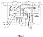
- 325 and 330 and inductors 305 and 310may be built into a multichip module 300 containing a detector 360 , an ADC 365 , a processor 355 , DACs 370 , voltage buffers, and charge pump 335 .
- This multichip module 300may be designed with a closed loop feedback system to maximize the RF voltage across the output node by adjusting all the PTC 320 , 325 and 330 bias voltages, and doing so independently.
- the RF matching networkmay be comprised of inductors L 1 310 , L 2 305 and variable capacitors PTC 1 320 , PTC 2 325 and PTC 3 330 .
- each variable capacitormay itself be a complex network.
- the RF voltage detector 360 in this AIMMmay be comprised of a resistive voltage divider (5K ⁇ /50 ⁇ ) and the simple diode detector.
- the controllermay be comprised of the analog-to-digital converter or ADC 1 355 , the microprocessor 355 , plus the digital-to-analog converters DAC 1 370 , DAC 2 375 and DAC 3 380 .
- the controllermay use external signals such as knowledge of frequency, Tx or Rx mode, or other available signals in the operation of its control algorithm.
- the bias voltage driver circuitmay be comprised of a DC-to-DC converter such as the charge pump 335 , in addition to the three analog buffers whose output voltage is labeled V bias1 , 385 , V bias 390 , and V bias3 395 .
- the DC-to-DC voltage convertermay be needed to supply a higher bias voltage from the analog buffers than what is normally required to power the processor 355 .
- the charge pumpmay supply a voltage in the range of 10 volts to 50 volts, and in some embodiments, both positive and negative supply voltages may be used.
- the RF matching network shown in FIG. 2is representative of many possible circuit topologies. Shown in FIG. 2 is a ladder network, but other topologies such as a T or Pi network may be used.
- the variable reactive elementsare shown in shunt connections but that is not a restriction, as they may be used in series in other applications.
- three independent variable capacitancesare shown in this RF matching network. However, fewer or more variable reactive elements may be used depending on the complexity needed to meet RF specifications.
- the inductors for the RF matching networkare shown to be included in the AIMM multichip module. In practice, this may not always be the case. If the module is extremely small, it may be more convenient to use external inductors for the matching network. External inductors may have a higher Q factor than smaller inductors that are able to be integrated on the module.
- the lowest cost RF voltage detectoris a simple diode detector, but it has a limited dynamic range of about 25 dB.
- Logarithmic amplifiersthat detect the signal envelope
- the variable voltage divider 430may be added between the RF output port 435 and the RF voltage detector 425 . It is controlled by the loop controller 420 (microprocessor, ASIC, etc), and therefore it is a programmable voltage divider.
- Bias voltage driver circuit 415 and RF matching network 410operate as described above with respect to FIG. 1 .
- an embodiment of the present inventionprovides a simple resistive voltage divider 550 which is implemented using a three-pole RF switch 560 to select one of three different resistances: R 1 530 , R 2 535 , or R 3 540 .
- typical valuesmay be 100 ⁇ , 1K ⁇ , and 10 K ⁇ .
- a typical value for R 4 565may be 50 ⁇ which would be a desirable value for most RF detector designs. Assuming a high input impedance for the detector 555 , the voltage coupling levels would then be 1 ⁇ 3, 1/21, and 1/201.
- variable voltage divider 550will allow the detector input port 505 to be more isolated at the higher power levels. This will improve linearity of the module for high signal levels.
- FIG. 6generally at 600 are the functional blocks of a variable voltage divider 640 , and the RF matching network 610 may be combined in hardware to some degree by understanding that the output node 625 of the matching network 610 may be connected to a shunt RF branch comprised of a series string of capacitors 660 and to impedance 635 .
- An input node for RF in 605may also be connected to the RF matching network 610 .
- This series string 660may be a RF voltage divider 640 , and by selectively tapping into various circuit nodes along the string, one may obtain a variable output voltage divider 640 . In an embodiment of the present invention, this is done with a digitally controlled RF switch 630 .
- the switch 630may be realized with FETs, MEMS, PIN diodes, or any other RF switch technology.
- RF voltage detector 655 and controller 620Associated with variable voltage divider 640 is RF voltage detector 655 and controller 620 , which is further connected to RF matching network 610 via bias voltage driver circuit 615 .
- the resistance of R 1 645will need to be much higher (>10 ⁇ ) than the reactance of the string of series capacitors 660 between the tap point and ground.
- An alternative circuit to FIG. 6would have the resistor R 1 645 moved to the capacitor side of the switch SW 1 630 and placed in each of the three lines going to the tap points. This will allow the resistors to be built on-chip with the tunable IC used in the matching network.
- Resister R 4may also be utilized at 650 .
- Some embodiments of the inventionmay be implemented, for example, using a machine-readable medium or article which may store an instruction or a set of instructions that, if executed by a machine, for example, by the system of FIG. 1 or FIG. 2 , by controller 125 and 235 in communication with bias voltage driver circuit 120 and 230 , by processor 355 of FIG. 3 , or by other suitable machines, cause the machine to perform a method and/or operations in accordance with embodiments of the invention.
- Such machinemay include, for example, any suitable processing platform, computing platform, computing device, processing device, computing system, processing system, computer, processor, or the like, and may be implemented using any suitable combination of hardware and/or software.
- the machine-readable medium or articlemay include, for example, any suitable type of memory unit, memory device, memory article, memory medium, storage device, storage article, storage medium and/or storage unit, for example, memory, removable or non-removable media, erasable or non-erasable media, writeable or re-writeable media, digital or analog media, hard disk, floppy disk, Compact Disk Read Only Memory (CD-ROM), Compact Disk Recordable (CD-R), Compact Disk Re-Writeable (CD-RW), optical disk, magnetic media, various types of Digital Versatile Disks (DVDs), a tape, a cassette, or the like.
- the instructionsmay include any suitable type of code, for example, source code, compiled code, interpreted code, executable code, static code, dynamic code, or the like, and may be implemented using any suitable high-level, low-level, object-oriented, visual, compiled and/or interpreted programming language, e.g., C, C++, Java, BASIC, Pascal, Fortran, Cobol, assembly language, machine code, or the like.
- codefor example, source code, compiled code, interpreted code, executable code, static code, dynamic code, or the like
- suitable high-level, low-level, object-oriented, visual, compiled and/or interpreted programming languagee.g., C, C++, Java, BASIC, Pascal, Fortran, Cobol, assembly language, machine code, or the like.
- An embodiment of the present inventionprovides a machine-accessible medium that provides instructions, which when accessed, cause a machine to perform operations comprising adapting an RF matching network to maximize RF power transferred from at least one RF input port to at least one RF output port by controlling the variation of the voltage or current to voltage or current controlled variable reactive elements in said RF matching network to maximize the RF voltage at said at least one RF output port.
- the machine-accessible medium of the present inventionmay further comprise said instructions causing said machine to perform operations further comprising receiving information from a voltage detector connected to said at least one RF output port which determines the voltage at said at least one RF output port and providing voltage information to a controller that controls a bias driving circuit which provides voltage or current bias to said RF matching network.
- Embodiments of the present inventionmay be implemented by software, by hardware, or by any combination of software and/or hardware as may be suitable for specific applications or in accordance with specific design requirements.
- Embodiments of the inventionmay include units and/or sub-units, which may be separate of each other or combined together, in whole or in part, and may be implemented using specific, multi-purpose or general processors or controllers, or devices as are known in the art.
- Some embodiments of the inventionmay include buffers, registers, stacks, storage units and/or memory units, for temporary or long-term storage of data or in order to facilitate the operation of a specific embodiment.
- BSTmay be used as a tunable dielectric material that may be used in a tunable dielectric capacitor of the present invention.
- Paratek Microwave, Inc.has developed and continues to develop tunable dielectric materials that may be utilized in embodiments of the present invention and thus the present invention is not limited to using BST material.
- This family of tunable dielectric materialsmay be referred to as Parascan®.
- Parascan®as used herein is a trademarked term indicating a tunable dielectric material developed by the assignee of the present invention.
- Parascan® tunable dielectric materialshave been described in several patents.
- Barium strontium titanate(BaTiO3-SrTiO3), also referred to as BSTO, is used for its high dielectric constant (200-6,000) and large change in dielectric constant with applied voltage (25-75 percent with a field of 2 Volts/micron).
- Tunable dielectric materials including barium strontium titanateare disclosed in U.S. Pat. No. 5,312,790 to Sengupta, et al. entitled “Ceramic Ferroelectric Material”; U.S. Pat. No.
- Barium strontium titanate of the formula Ba x Sr 1-x TiO 3is a preferred electronically tunable dielectric material due to its favorable tuning characteristics, low Curie temperatures and low microwave loss properties.
- xcan be any value from 0 to 1, preferably from about 0.15 to about 0.6. More preferably, x is from 0.3 to 0.6.
- Other electronically tunable dielectric materialsmay be used partially or entirely in place of barium strontium titanate.
- An exampleis Ba x Ca 1-x TiO 3 , where x is in a range from about 0.2 to about 0.8, preferably from about 0.4 to about 0.6.
- Additional electronically tunable ferroelectricsinclude Pb x Zr 1-x TiO 3 (PZT) where x ranges from about 0.0 to about 1.0, Pb x Zr 1-x SrTiO 3 where x ranges from about 0.05 to about 0.4, KTa x Nb 1-x O 3 where x ranges from about 0.0 to about 1.0, lead lanthanum zirconium titanate (PLZT), PbTiO 3 , BaCaZrTiO 3 , NaNO 3 , KNbO 3 , LiNbO 3 , LiTaO 3 , PbNb 2 O 6 , PbTa 2 O 6 , KSr(NbO 3 ) and NaBa 2 (NbO 3 )5KH 2 PO 4 , and mixtures and compositions thereof.
- PZTPb x Zr 1-x TiO 3
- Pb x Zr 1-x SrTiO 3where x ranges from about 0.05 to about
- these materialscan be combined with low loss dielectric materials, such as magnesium oxide (MgO), aluminum oxide (Al 2 O 3 ), and zirconium oxide (ZrO 2 ), and/or with additional doping elements, such as manganese (MN), iron (Fe), and tungsten (W), or with other alkali earth metal oxides (i.e. calcium oxide, etc.), transition metal oxides, silicates, niobates, tantalates, aluminates, zirconnates, and titanates to further reduce the dielectric loss.
- MgOmagnesium oxide
- Al 2 O 3aluminum oxide
- ZrO 2zirconium oxide
- additional doping elementssuch as manganese (MN), iron (Fe), and tungsten (W), or with other alkali earth metal oxides (i.e. calcium oxide, etc.), transition metal oxides, silicates, niobates, tantalates, aluminates, zirconnates, and titanates to further reduce the dielectric loss.
- the tunable dielectric materialscan also be combined with one or more non-tunable dielectric materials.
- the non-tunable phase(s)may include MgO, MgAl 2 O 4 , MgTiO 3 , Mg 2 SiO 4 , CaSiO 3 , MgSrZrTiO 6 , CaTiO 3 , Al 2 O 3 , Sio 2 and/or other metal silicates such as BaSiO 3 and SrSiO 3 .
- the non-tunable dielectric phasesmay be any combination of the above, e.g., MgO combined with MgTiO 3 , MgO combined with MgSrZrTiO 6 , MgO combined with Mg 2 SiO 4 , MgO combined with Mg 2 SiO 4 , Mg 2 SiO 4 combined with CaTiO 3 and the like.
- minor additivesin amounts of from about 0.1 to about 5 weight percent can be added to the composites to additionally improve the electronic properties of the films.
- These minor additivesinclude oxides such as zirconnates, tannates, rare earths, niobates and tantalates.
- the minor additivesmay include CaZrO 3 , BaZrO 3 , SrZrO 3 , BaSnO 3 , CaSnO 3 , MgSnO 3 , Bi2O 3 /2SnO 2 , Nd 2 O 3 , Pr 7 O 11 , Yb 2 O 3 , H o2 O 3 , La 2 O 3 , MgNb 2 O 6 , SrNb 2 O 6 , BaNb 2 O 6 , MgTa 2 O 6 , BaTa 2 O 6 and Ta 2 O 3 .
- Films of tunable dielectric compositesmay comprise Ba1-xSrxTiO3, where x is from 0.3 to 0.7 in combination with at least one non-tunable dielectric phase selected from MgO, MgTiO 3 , MgZrO 3 , MgSrZrTiO 6 , Mg 2 SiO 4 , CaSiO 3 , MgAl 2 O 4 , CaTiO 3 , Al 2 O 3 , SiO 2 , BaSiO 3 and SrSiO 3 .
- These compositionscan be BSTO and one of these components, or two or more of these components in quantities from 0.25 weight percent to 80 weight percent with BSTO weight ratios of 99.75 weight percent to 20 weight percent.
- the electronically tunable materialsmay also include at least one metal silicate phase.
- the metal silicatesmay include metals from Group 2A of the Periodic Table, i.e., Be, Mg, Ca, Sr, Ba and Ra, preferably Mg, Ca, Sr and Ba.
- Preferred metal silicatesinclude Mg 2 SiO 4 , CaSiO 3 , BaSiO 3 and SrSiO 3 .
- the present metal silicatesmay include metals from Group 1A, i.e., Li, Na, K, Rb, Cs and Fr, preferably Li, Na and K.
- such metal silicatesmay include sodium silicates such as Na 2 SiO 3 and NaSiO 3 -5H 2 O, and lithium-containing silicates such as LiAlSiO 4 , Li2SiO 3 and Li 4 SiO 4 .
- Metals from Groups 3A, 4A and some transition metals of the Periodic Tablemay also be suitable constituents of the metal silicate phase.
- Additional metal silicatesmay include Al 2 Si 2 O 7 , ZrSiO 4 , KalSi 3 O 8 , NaAlSi 3 O 8 , CaAl 2 Si 2 O 8 , CaMgSi 2 O 6 , BaTiSi 3 O 9 and Zn 2 SiO 4 .
- the above tunable materialscan be tuned at room temperature by controlling an electric field that is applied across the materials.
- the electronically tunable materialscan include at least two additional metal oxide phases.
- the additional metal oxidesmay include metals from Group 2A of the Periodic Table, i.e., Mg, Ca, Sr, Ba, Be and Ra, preferably Mg, Ca, Sr and Ba.
- the additional metal oxidesmay also include metals from Group 1A, i.e., Li, Na, K, Rb, Cs and Fr, preferably Li, Na and K.
- Metals from other Groups of the Periodic Tablemay also be suitable constituents of the metal oxide phases.
- refractory metalssuch as Ti, V, Cr, Mn, Zr, Nb, Mo, Hf, Ta and W may be used.
- metalssuch as Al, Si, Sn, Pb and Bi may be used.
- the metal oxide phasesmay comprise rare earth metals such as Sc, Y, La, Ce, Pr, Nd and the like.
- the additional metal oxidesmay include, for example, zirconnates, silicates, titanates, aluminates, stannates, niobates, tantalates and rare earth oxides.
- Preferred additional metal oxidesinclude Mg 2 SiO 4 , MgO, CaTiO 3 , MgZrSrTiO 6 , MgTiO 3 , MgA 12 O 4 , WO3, SnTiO 4 , ZrTiO 4 , CaSiO 3 , CaSnO 3 , CaWO 4 , CaZrO 3 , MgTa 2 O 6 , MgZrO 3 , MnO 2 , PbO, Bi 2 O 3 and La 2 O 3 .
- Particularly preferred additional metal oxidesinclude Mg 2 SiO 4 , MgO, CaTiO 3 , MgZrSrTiO 6 , MgTiO 3 , MgAl 2 O 4 , MgTa 2 O 6 and MgZrO 3 .
- the additional metal oxide phasesare typically present in total amounts of from about 1 to about 80 weight percent of the material, preferably from about 3 to about 65 weight percent, and more preferably from about 5 to about 60 weight percent.
- the additional metal oxidescomprise from about 10 to about 50 total weight percent of the material.
- the individual amount of each additional metal oxidemay be adjusted to provide the desired properties.
- their weight ratiosmay vary, for example, from about 1:100 to about 100:1, typically from about 1:10 to about 10:1 or from about 1:5 to about 5:1.
- metal oxides in total amounts of from 1 to 80 weight percentare typically used, smaller additive amounts of from 0.01 to 1 weight percent may be used for some applications.
- the additional metal oxide phasescan include at least two Mg-containing compounds.
- the materialmay optionally include Mg-free compounds, for example, oxides of metals selected from Si, Ca, Zr, Ti, Al and/or rare earths.
Landscapes
- Engineering & Computer Science (AREA)
- Computer Networks & Wireless Communication (AREA)
- Signal Processing (AREA)
- Transmitters (AREA)
- Amplifiers (AREA)
Abstract
Description
- (1) The cost of the coupler,
- (2) The physical size of the directional coupler may be prohibitive: Broadband couplers are typically ¼ of a guide wavelength in total transmission line length at their mid-band frequency. For a 900 MHz band and an effective dielectric constant of 4, the total line length needs to be about 1.64 inches.
- (3) The directivity of the directional coupler sets the lower limit on the achievable input return loss of the RF matching network. For instance, a directional coupler with 20 db of coupling will limit the input return loss for the AIMM to about −20 dB.
- (4) Directional couplers have limited operational bandwidth, where the directivity meets a certain specification. In some applications, the AIMM may need to work at different frequency bands separated by an octave or more, such as at 900 MHz and 1900 MHz in a commercial mobile phone.
- 2—Limit the allowed tuning to avoid certain matching impedances, or put the tuner in a “default” position when the cellular handset transmitter is at the full power step. By doing so at the highest power level, we can avoid having the handset antenna couple higher power into the human tissue near the phone's antenna. It is only at the highest power level where the SAR limit typically becomes an issue, and by limiting the effectiveness of the AIMM tuner at this power level, we can avoid the possibility of causing the handset to exceed the SAR limits.
- 3—In order to allow the AIMM tuner to achieve the optimal match as quickly as possible, a memory system could be engaged in which the optimal match is stored for each frequency band, or perhaps even for each group of channels, and this memorized optimal match is used as the starting position any time the phone is directed to that particular band or channel. This memory could also remember operating positions such as flip-open or flip-closed in order to better “guess” the best starting position for the matching network.
Claims (29)
Priority Applications (4)
| Application Number | Priority Date | Filing Date | Title |
|---|---|---|---|
| US12/287,599US7852170B2 (en) | 2006-11-08 | 2008-10-10 | Adaptive impedance matching apparatus, system and method with improved dynamic range |
| US12/939,110US8680934B2 (en) | 2006-11-08 | 2010-11-03 | System for establishing communication with a mobile device server |
| US14/169,599US9419581B2 (en) | 2006-11-08 | 2014-01-31 | Adaptive impedance matching apparatus, system and method with improved dynamic range |
| US15/205,595US10020828B2 (en) | 2006-11-08 | 2016-07-08 | Adaptive impedance matching apparatus, system and method with improved dynamic range |
Applications Claiming Priority (2)
| Application Number | Priority Date | Filing Date | Title |
|---|---|---|---|
| US11/594,309US7535312B2 (en) | 2006-11-08 | 2006-11-08 | Adaptive impedance matching apparatus, system and method with improved dynamic range |
| US12/287,599US7852170B2 (en) | 2006-11-08 | 2008-10-10 | Adaptive impedance matching apparatus, system and method with improved dynamic range |
Related Parent Applications (1)
| Application Number | Title | Priority Date | Filing Date |
|---|---|---|---|
| US11/594,309DivisionUS7535312B2 (en) | 2006-11-08 | 2006-11-08 | Adaptive impedance matching apparatus, system and method with improved dynamic range |
Related Child Applications (1)
| Application Number | Title | Priority Date | Filing Date |
|---|---|---|---|
| US12/939,110ContinuationUS8680934B2 (en) | 2006-11-08 | 2010-11-03 | System for establishing communication with a mobile device server |
Publications (2)
| Publication Number | Publication Date |
|---|---|
| US20090039976A1 US20090039976A1 (en) | 2009-02-12 |
| US7852170B2true US7852170B2 (en) | 2010-12-14 |
Family
ID=39359238
Family Applications (5)
| Application Number | Title | Priority Date | Filing Date |
|---|---|---|---|
| US11/594,309Active2027-03-23US7535312B2 (en) | 2006-11-08 | 2006-11-08 | Adaptive impedance matching apparatus, system and method with improved dynamic range |
| US12/287,599ActiveUS7852170B2 (en) | 2006-11-08 | 2008-10-10 | Adaptive impedance matching apparatus, system and method with improved dynamic range |
| US12/939,110Active2027-10-19US8680934B2 (en) | 2006-11-08 | 2010-11-03 | System for establishing communication with a mobile device server |
| US14/169,599Active2027-08-31US9419581B2 (en) | 2006-11-08 | 2014-01-31 | Adaptive impedance matching apparatus, system and method with improved dynamic range |
| US15/205,595ActiveUS10020828B2 (en) | 2006-11-08 | 2016-07-08 | Adaptive impedance matching apparatus, system and method with improved dynamic range |
Family Applications Before (1)
| Application Number | Title | Priority Date | Filing Date |
|---|---|---|---|
| US11/594,309Active2027-03-23US7535312B2 (en) | 2006-11-08 | 2006-11-08 | Adaptive impedance matching apparatus, system and method with improved dynamic range |
Family Applications After (3)
| Application Number | Title | Priority Date | Filing Date |
|---|---|---|---|
| US12/939,110Active2027-10-19US8680934B2 (en) | 2006-11-08 | 2010-11-03 | System for establishing communication with a mobile device server |
| US14/169,599Active2027-08-31US9419581B2 (en) | 2006-11-08 | 2014-01-31 | Adaptive impedance matching apparatus, system and method with improved dynamic range |
| US15/205,595ActiveUS10020828B2 (en) | 2006-11-08 | 2016-07-08 | Adaptive impedance matching apparatus, system and method with improved dynamic range |
Country Status (1)
| Country | Link |
|---|---|
| US (5) | US7535312B2 (en) |
Cited By (70)
| Publication number | Priority date | Publication date | Assignee | Title |
|---|---|---|---|---|
| US20100001768A1 (en)* | 2007-01-18 | 2010-01-07 | Adrianus Van Bezooijen | MEMS Capacitor Circuit and Method |
| US20100182216A1 (en)* | 2009-01-22 | 2010-07-22 | Edgar Schmidhammer | Adaptive Impedance Matching Circuit and Method for Matching for Duplex Operation Standards |
| US20110043298A1 (en)* | 2006-11-08 | 2011-02-24 | Paratek Microwave, Inc. | System for establishing communication with a mobile device server |
| US8217732B2 (en) | 2006-11-08 | 2012-07-10 | Paratek Microwave, Inc. | Method and apparatus for adaptive impedance matching |
| US8269683B2 (en) | 2006-01-14 | 2012-09-18 | Research In Motion Rf, Inc. | Adaptively tunable antennas and method of operation therefore |
| US8299867B2 (en) | 2006-11-08 | 2012-10-30 | Research In Motion Rf, Inc. | Adaptive impedance matching module |
| US8325097B2 (en) | 2006-01-14 | 2012-12-04 | Research In Motion Rf, Inc. | Adaptively tunable antennas and method of operation therefore |
| US8421548B2 (en) | 2008-09-24 | 2013-04-16 | Research In Motion Rf, Inc. | Methods for tuning an adaptive impedance matching network with a look-up table |
| US8457569B2 (en) | 2007-05-07 | 2013-06-04 | Research In Motion Rf, Inc. | Hybrid techniques for antenna retuning utilizing transmit and receive power information |
| US8472888B2 (en) | 2009-08-25 | 2013-06-25 | Research In Motion Rf, Inc. | Method and apparatus for calibrating a communication device |
| US8620236B2 (en) | 2007-04-23 | 2013-12-31 | Blackberry Limited | Techniques for improved adaptive impedance matching |
| US8620246B2 (en) | 2006-01-14 | 2013-12-31 | Blackberry Limited | Adaptive impedance matching module (AIMM) control architectures |
| US8655286B2 (en) | 2011-02-25 | 2014-02-18 | Blackberry Limited | Method and apparatus for tuning a communication device |
| US8693963B2 (en) | 2000-07-20 | 2014-04-08 | Blackberry Limited | Tunable microwave devices with auto-adjusting matching circuit |
| USRE44998E1 (en) | 2000-07-20 | 2014-07-08 | Blackberry Limited | Optimized thin film capacitors |
| US8798555B2 (en) | 2007-11-14 | 2014-08-05 | Blackberry Limited | Tuning matching circuits for transmitter and receiver bands as a function of the transmitter metrics |
| US8803631B2 (en) | 2010-03-22 | 2014-08-12 | Blackberry Limited | Method and apparatus for adapting a variable impedance network |
| US8860525B2 (en) | 2010-04-20 | 2014-10-14 | Blackberry Limited | Method and apparatus for managing interference in a communication device |
| US8948889B2 (en) | 2012-06-01 | 2015-02-03 | Blackberry Limited | Methods and apparatus for tuning circuit components of a communication device |
| US9026062B2 (en) | 2009-10-10 | 2015-05-05 | Blackberry Limited | Method and apparatus for managing operations of a communication device |
| US9196459B2 (en) | 2014-01-10 | 2015-11-24 | Reno Technologies, Inc. | RF impedance matching network |
| US9231643B2 (en) | 2011-02-18 | 2016-01-05 | Blackberry Limited | Method and apparatus for radio antenna frequency tuning |
| US9246223B2 (en) | 2012-07-17 | 2016-01-26 | Blackberry Limited | Antenna tuning for multiband operation |
| US9263806B2 (en) | 2010-11-08 | 2016-02-16 | Blackberry Limited | Method and apparatus for tuning antennas in a communication device |
| US9306533B1 (en) | 2015-02-20 | 2016-04-05 | Reno Technologies, Inc. | RF impedance matching network |
| US9350405B2 (en) | 2012-07-19 | 2016-05-24 | Blackberry Limited | Method and apparatus for antenna tuning and power consumption management in a communication device |
| US9362891B2 (en) | 2012-07-26 | 2016-06-07 | Blackberry Limited | Methods and apparatus for tuning a communication device |
| US9374113B2 (en) | 2012-12-21 | 2016-06-21 | Blackberry Limited | Method and apparatus for adjusting the timing of radio antenna tuning |
| US9406444B2 (en) | 2005-11-14 | 2016-08-02 | Blackberry Limited | Thin film capacitors |
| US9413066B2 (en) | 2012-07-19 | 2016-08-09 | Blackberry Limited | Method and apparatus for beam forming and antenna tuning in a communication device |
| US9496122B1 (en) | 2014-01-10 | 2016-11-15 | Reno Technologies, Inc. | Electronically variable capacitor and RF matching network incorporating same |
| US9525412B2 (en) | 2015-02-18 | 2016-12-20 | Reno Technologies, Inc. | Switching circuit |
| US9697991B2 (en) | 2014-01-10 | 2017-07-04 | Reno Technologies, Inc. | RF impedance matching network |
| US9716311B2 (en) | 2011-05-16 | 2017-07-25 | Blackberry Limited | Method and apparatus for tuning a communication device |
| US9729122B2 (en) | 2015-02-18 | 2017-08-08 | Reno Technologies, Inc. | Switching circuit |
| US9755641B1 (en) | 2014-01-10 | 2017-09-05 | Reno Technologies, Inc. | High speed high voltage switching circuit |
| US9769826B2 (en) | 2011-08-05 | 2017-09-19 | Blackberry Limited | Method and apparatus for band tuning in a communication device |
| US9844127B2 (en) | 2014-01-10 | 2017-12-12 | Reno Technologies, Inc. | High voltage switching circuit |
| US9853363B2 (en) | 2012-07-06 | 2017-12-26 | Blackberry Limited | Methods and apparatus to control mutual coupling between antennas |
| US9865432B1 (en) | 2014-01-10 | 2018-01-09 | Reno Technologies, Inc. | RF impedance matching network |
| US10003393B2 (en) | 2014-12-16 | 2018-06-19 | Blackberry Limited | Method and apparatus for antenna selection |
| US10340879B2 (en) | 2015-02-18 | 2019-07-02 | Reno Technologies, Inc. | Switching circuit |
| US10404295B2 (en) | 2012-12-21 | 2019-09-03 | Blackberry Limited | Method and apparatus for adjusting the timing of radio antenna tuning |
| US10431428B2 (en) | 2014-01-10 | 2019-10-01 | Reno Technologies, Inc. | System for providing variable capacitance |
| US10455729B2 (en) | 2014-01-10 | 2019-10-22 | Reno Technologies, Inc. | Enclosure cooling system |
| US20190334633A1 (en)* | 2016-06-28 | 2019-10-31 | Patrick Adamo | Antenna Status Remote Monitoring System |
| US10483090B2 (en) | 2017-07-10 | 2019-11-19 | Reno Technologies, Inc. | Restricted capacitor switching |
| US10692699B2 (en) | 2015-06-29 | 2020-06-23 | Reno Technologies, Inc. | Impedance matching with restricted capacitor switching |
| US10714314B1 (en) | 2017-07-10 | 2020-07-14 | Reno Technologies, Inc. | Impedance matching network and method |
| US10727029B2 (en) | 2017-07-10 | 2020-07-28 | Reno Technologies, Inc | Impedance matching using independent capacitance and frequency control |
| US10984986B2 (en) | 2015-06-29 | 2021-04-20 | Reno Technologies, Inc. | Impedance matching network and method |
| US11081316B2 (en) | 2015-06-29 | 2021-08-03 | Reno Technologies, Inc. | Impedance matching network and method |
| US11101110B2 (en) | 2017-07-10 | 2021-08-24 | Reno Technologies, Inc. | Impedance matching network and method |
| US11114280B2 (en) | 2017-07-10 | 2021-09-07 | Reno Technologies, Inc. | Impedance matching with multi-level power setpoint |
| US11150283B2 (en) | 2015-06-29 | 2021-10-19 | Reno Technologies, Inc. | Amplitude and phase detection circuit |
| US11289307B2 (en) | 2017-07-10 | 2022-03-29 | Reno Technologies, Inc. | Impedance matching network and method |
| US11315758B2 (en) | 2017-07-10 | 2022-04-26 | Reno Technologies, Inc. | Impedance matching using electronically variable capacitance and frequency considerations |
| US11335540B2 (en) | 2015-06-29 | 2022-05-17 | Reno Technologies, Inc. | Impedance matching network and method |
| US11342161B2 (en) | 2015-06-29 | 2022-05-24 | Reno Technologies, Inc. | Switching circuit with voltage bias |
| US11342160B2 (en) | 2015-06-29 | 2022-05-24 | Reno Technologies, Inc. | Filter for impedance matching |
| US11393659B2 (en) | 2017-07-10 | 2022-07-19 | Reno Technologies, Inc. | Impedance matching network and method |
| US11398370B2 (en) | 2017-07-10 | 2022-07-26 | Reno Technologies, Inc. | Semiconductor manufacturing using artificial intelligence |
| US11476091B2 (en) | 2017-07-10 | 2022-10-18 | Reno Technologies, Inc. | Impedance matching network for diagnosing plasma chamber |
| US11521831B2 (en) | 2019-05-21 | 2022-12-06 | Reno Technologies, Inc. | Impedance matching network and method with reduced memory requirements |
| US11521833B2 (en) | 2017-07-10 | 2022-12-06 | Reno Technologies, Inc. | Combined RF generator and RF solid-state matching network |
| US11631570B2 (en) | 2015-02-18 | 2023-04-18 | Reno Technologies, Inc. | Switching circuit |
| US12119206B2 (en) | 2015-02-18 | 2024-10-15 | Asm America, Inc. | Switching circuit |
| US12272522B2 (en) | 2017-07-10 | 2025-04-08 | Asm America, Inc. | Resonant filter for solid state RF impedance matching network |
| US12334307B2 (en) | 2017-07-10 | 2025-06-17 | Asm Ip Holding B.V. | Power control for rf impedance matching network |
| US12444573B2 (en) | 2022-04-18 | 2025-10-14 | Asm America, Inc. | Impedance matching network and method |
Families Citing this family (38)
| Publication number | Priority date | Publication date | Assignee | Title |
|---|---|---|---|---|
| US20090267703A1 (en)* | 2008-04-23 | 2009-10-29 | Andrzej May | Dynamically adaptable impedance matching circuitry between an electro-optical load and a driving source |
| US8447255B2 (en)* | 2008-10-28 | 2013-05-21 | Sony Ericsson Mobile Communications Ab | Variable impedance matching network and method for the same |
| US8774743B2 (en)* | 2009-10-14 | 2014-07-08 | Blackberry Limited | Dynamic real-time calibration for antenna matching in a radio frequency receiver system |
| US8285228B2 (en)* | 2010-04-12 | 2012-10-09 | Mediatek Inc. | Signal transmitting circuit and related method |
| US8294632B2 (en)* | 2010-05-18 | 2012-10-23 | Sony Ericsson Mobile Communications Ab | Antenna interface circuits including tunable impedance matching networks, electronic devices incorporating the same, and methods of tuning antenna interface circuits |
| US8294514B2 (en) | 2010-09-24 | 2012-10-23 | St-Ericsson Sa | Calibrate output matching for correct output power |
| WO2012129348A2 (en)* | 2011-03-21 | 2012-09-27 | Wispry, Inc. | Simple and minimally invasive methods and systems for sensing and computing load impedance |
| US8674782B2 (en)* | 2011-03-31 | 2014-03-18 | Texas Instruments Incorporated | RF impedance detection using two point voltage sampling |
| CA2836419C (en)* | 2011-05-16 | 2016-11-29 | Gregory MENDOLIA | Method and apparatus for tuning a communication device |
| US8626083B2 (en) | 2011-05-16 | 2014-01-07 | Blackberry Limited | Method and apparatus for tuning a communication device |
| KR101294434B1 (en)* | 2011-07-28 | 2013-08-07 | 엘지이노텍 주식회사 | Impedance matching apparatus and impedance matching method |
| CN103891047B (en)* | 2011-10-26 | 2017-04-05 | 株式会社村田制作所 | Variable-capacitance element and high-frequency element |
| CN103891046B (en)* | 2011-10-26 | 2016-05-04 | 株式会社村田制作所 | communication circuit |
| US9002278B2 (en)* | 2012-02-29 | 2015-04-07 | Htc Corporation | Simple automatic antenna tuning system and method |
| EP2722996B1 (en) | 2012-10-22 | 2014-12-17 | BlackBerry Limited | Method and apparatus for radio frequency tuning utilizing a determined use case |
| US9851384B2 (en) | 2012-11-22 | 2017-12-26 | Qualcomm Incorporated | Multi-band impedance detector |
| JP5713150B2 (en)* | 2013-03-29 | 2015-05-07 | 株式会社村田製作所 | Variable capacitance element and communication device |
| WO2014184676A2 (en)* | 2013-04-15 | 2014-11-20 | Schrader Electronics Limited | Multi-frequency tire pressure monitoring detector |
| US9537217B2 (en)* | 2013-09-27 | 2017-01-03 | Blackberry Limited | Broadband capacitively-loaded tunable antenna |
| US9985353B1 (en) | 2013-09-30 | 2018-05-29 | Ethertronics, Inc. | Antenna system for metallized devices |
| US11452982B2 (en) | 2015-10-01 | 2022-09-27 | Milton Roy, Llc | Reactor for liquid and gas and method of use |
| EP3356026B1 (en) | 2015-10-01 | 2022-11-09 | Milton Roy, LLC | Plasma reactor for liquid and gas |
| US12296313B2 (en) | 2015-10-01 | 2025-05-13 | Milton Roy, Llc | System and method for formulating medical treatment effluents |
| US10882021B2 (en) | 2015-10-01 | 2021-01-05 | Ion Inject Technology Llc | Plasma reactor for liquid and gas and method of use |
| US10187968B2 (en)* | 2015-10-08 | 2019-01-22 | Ion Inject Technology Llc | Quasi-resonant plasma voltage generator |
| US10046300B2 (en) | 2015-12-09 | 2018-08-14 | Ion Inject Technology Llc | Membrane plasma reactor |
| US9548734B1 (en)* | 2015-12-26 | 2017-01-17 | Intel Corporation | Smart impedance matching for high-speed I/O |
| US10431889B2 (en)* | 2016-04-22 | 2019-10-01 | The Charles Stark Draper Laboratory, Inc. | Low-loss compact transmit impedance matching tuning technique |
| FR3053185A1 (en) | 2016-06-22 | 2017-12-29 | Tekcem | METHOD FOR THE AUTOMATIC ADJUSTMENT OF A TUNABLE ADAPTATION CIRCUIT, AND AUTOMATIC TUNING SYSTEM USING THE SAME. |
| FR3053546A1 (en) | 2016-06-30 | 2018-01-05 | Tekcem | METHOD OF AUTOMATICALLY ADJUSTING A TUNABLE ADAPTATION CIRCUIT, AND AUTOMATIC TUNING SYSTEM USING THE SAME |
| TWI625043B (en)* | 2017-02-16 | 2018-05-21 | Antenna matching device of dual-frequency tire pressure sensor | |
| US9973940B1 (en) | 2017-02-27 | 2018-05-15 | At&T Intellectual Property I, L.P. | Apparatus and methods for dynamic impedance matching of a guided wave launcher |
| US10044380B1 (en) | 2017-10-18 | 2018-08-07 | Tekcem | Method for automatic adjustment of a tunable passive antenna and a tuning unit, and apparatus for radio communication using this method |
| US9991911B1 (en) | 2017-10-19 | 2018-06-05 | Tekcem | Method for automatically adjusting a tunable passive antenna and a tuning unit, and apparatus for radio communication using this method |
| US10305192B1 (en) | 2018-08-13 | 2019-05-28 | At&T Intellectual Property I, L.P. | System and method for launching guided electromagnetic waves with impedance matching |
| WO2020139681A1 (en)* | 2018-12-26 | 2020-07-02 | Avx Corporation | System and method for controlling a voltage tunable multilayer capacitor |
| EP3886243B1 (en) | 2020-03-27 | 2025-10-15 | Nokia Technologies Oy | A radio-frequency switching apparatus |
| CN117500138B (en)* | 2023-10-19 | 2024-04-26 | 国电投核力同创(北京)科技有限公司 | Beam load dynamic matching method for low-frequency, high-energy and high-current accelerator |
Citations (126)
| Publication number | Priority date | Publication date | Assignee | Title |
|---|---|---|---|---|
| US2745067A (en) | 1951-06-28 | 1956-05-08 | True Virgil | Automatic impedance matching apparatus |
| US3117279A (en) | 1962-06-04 | 1964-01-07 | Collins Radio Co | Automatically controlled antenna tuning and loading system |
| US3160832A (en) | 1961-12-22 | 1964-12-08 | Collins Radio Co | Automatic coupling and impedance matching network |
| US3390337A (en) | 1966-03-15 | 1968-06-25 | Avco Corp | Band changing and automatic tuning apparatus for transmitter tau-pad output filter |
| US3443231A (en) | 1966-04-27 | 1969-05-06 | Gulf General Atomic Inc | Impedance matching system |
| US3509500A (en) | 1966-12-05 | 1970-04-28 | Avco Corp | Automatic digital tuning apparatus |
| US3571716A (en) | 1968-04-16 | 1971-03-23 | Motorola Inc | Electronically tuned antenna system |
| US3590385A (en) | 1969-07-25 | 1971-06-29 | Avco Corp | Semi-automatic tuning circuit for an antenna coupler |
| US3601717A (en) | 1969-11-20 | 1971-08-24 | Gen Dynamics Corp | System for automatically matching a radio frequency power output circuit to a load |
| US3794941A (en) | 1972-05-08 | 1974-02-26 | Hughes Aircraft Co | Automatic antenna impedance tuner including digital control circuits |
| US3919644A (en) | 1970-02-02 | 1975-11-11 | Gen Dynamics Corp | Automatic antenna coupler utilizing system for measuring the real part of the complex impedance or admittance presented by an antenna or other network |
| US3990024A (en) | 1975-01-06 | 1976-11-02 | Xerox Corporation | Microstrip/stripline impedance transformer |
| US3995237A (en) | 1974-10-15 | 1976-11-30 | Cincinnati Electronics Corporation | Automatic matching method and apparatus |
| US4186359A (en) | 1977-08-22 | 1980-01-29 | Tx Rx Systems Inc. | Notch filter network |
| US4201960A (en) | 1978-05-24 | 1980-05-06 | Motorola, Inc. | Method for automatically matching a radio frequency transmitter to an antenna |
| US4227256A (en) | 1978-01-06 | 1980-10-07 | Quadracast Systems, Inc. | AM Broadcast tuner with automatic gain control |
| US4493112A (en) | 1981-11-19 | 1985-01-08 | Rockwell International Corporation | Antenna tuner discriminator |
| US4799066A (en) | 1985-07-26 | 1989-01-17 | The Marconi Company Limited | Impedance matching arrangement |
| US5032805A (en) | 1989-10-23 | 1991-07-16 | The United States Of America As Represented By The Secretary Of The Army | RF phase shifter |
| US5142255A (en) | 1990-05-07 | 1992-08-25 | The Texas A&M University System | Planar active endfire radiating elements and coplanar waveguide filters with wide electronic tuning bandwidth |
| US5195045A (en) | 1991-02-27 | 1993-03-16 | Astec America, Inc. | Automatic impedance matching apparatus and method |
| US5200826A (en) | 1990-06-21 | 1993-04-06 | Samsung Electronics Co., Ltd. | TV signal receiving double conversion television tuner system having automatic gain control provisions |
| US5212463A (en) | 1992-07-22 | 1993-05-18 | The United States Of America As Represented By The Secretary Of The Army | Planar ferro-electric phase shifter |
| US5258728A (en) | 1987-09-30 | 1993-11-02 | Fujitsu Ten Limited | Antenna circuit for a multi-band antenna |
| US5301358A (en) | 1988-12-05 | 1994-04-05 | Seiko Corp. | Automatic antenna tuning method and apparatus |
| US5307033A (en) | 1993-01-19 | 1994-04-26 | The United States Of America As Represented By The Secretary Of The Army | Planar digital ferroelectric phase shifter |
| US5312790A (en) | 1993-06-09 | 1994-05-17 | The United States Of America As Represented By The Secretary Of The Army | Ceramic ferroelectric material |
| US5334958A (en) | 1993-07-06 | 1994-08-02 | The United States Of America As Represented By The Secretary Of The Army | Microwave ferroelectric phase shifters and methods for fabricating the same |
| US5409889A (en) | 1993-05-03 | 1995-04-25 | Das; Satyendranath | Ferroelectric high Tc superconductor RF phase shifter |
| US5430417A (en) | 1991-07-05 | 1995-07-04 | Aft Advanced Ferrite Technology Gmbh | Tunable matching network |
| US5446447A (en) | 1994-02-16 | 1995-08-29 | Motorola, Inc. | RF tagging system including RF tags with variable frequency resonant circuits |
| US5451567A (en) | 1994-03-30 | 1995-09-19 | Das; Satyendranath | High power ferroelectric RF phase shifter |
| US5451914A (en) | 1994-07-05 | 1995-09-19 | Motorola, Inc. | Multi-layer radio frequency transformer |
| US5457394A (en) | 1993-04-12 | 1995-10-10 | The Regents Of The University Of California | Impulse radar studfinder |
| US5472935A (en) | 1992-12-01 | 1995-12-05 | Yandrofski; Robert M. | Tuneable microwave devices incorporating high temperature superconducting and ferroelectric films |
| US5479139A (en) | 1995-04-19 | 1995-12-26 | The United States Of America As Represented By The Secretary Of The Army | System and method for calibrating a ferroelectric phase shifter |
| US5496795A (en) | 1994-08-16 | 1996-03-05 | Das; Satyendranath | High TC superconducting monolithic ferroelectric junable b and pass filter |
| US5502372A (en) | 1994-10-07 | 1996-03-26 | Hughes Aircraft Company | Microstrip diagnostic probe for thick metal flared notch and ridged waveguide radiators |
| US5524281A (en) | 1988-03-31 | 1996-06-04 | Wiltron Company | Apparatus and method for measuring the phase and magnitude of microwave signals |
| US5561407A (en) | 1995-01-31 | 1996-10-01 | The United States Of America As Represented By The Secretary Of The Army | Single substrate planar digital ferroelectric phase shifter |
| US5564086A (en) | 1993-11-29 | 1996-10-08 | Motorola, Inc. | Method and apparatus for enhancing an operating characteristic of a radio transmitter |
| US5593495A (en) | 1994-06-16 | 1997-01-14 | Sharp Kabushiki Kaisha | Method for manufacturing thin film of composite metal-oxide dielectric |
| US5635433A (en) | 1995-09-11 | 1997-06-03 | The United States Of America As Represented By The Secretary Of The Army | Ceramic ferroelectric composite material-BSTO-ZnO |
| US5635434A (en) | 1995-09-11 | 1997-06-03 | The United States Of America As Represented By The Secretary Of The Army | Ceramic ferroelectric composite material-BSTO-magnesium based compound |
| US5640042A (en) | 1995-12-14 | 1997-06-17 | The United States Of America As Represented By The Secretary Of The Army | Thin film ferroelectric varactor |
| US5679624A (en) | 1995-02-24 | 1997-10-21 | Das; Satyendranath | High Tc superconductive KTN ferroelectric time delay device |
| US5689219A (en) | 1994-06-30 | 1997-11-18 | Nokia Telecommunications Oy | Summing network |
| US5694134A (en) | 1992-12-01 | 1997-12-02 | Superconducting Core Technologies, Inc. | Phased array antenna system including a coplanar waveguide feed arrangement |
| US5693429A (en) | 1995-01-20 | 1997-12-02 | The United States Of America As Represented By The Secretary Of The Army | Electronically graded multilayer ferroelectric composites |
| US5699071A (en) | 1991-03-26 | 1997-12-16 | Sumitomo Chemical Company, Limited | Glass antenna system for automobile |
| US5766697A (en) | 1995-12-08 | 1998-06-16 | The United States Of America As Represented By The Secretary Of The Army | Method of making ferrolectric thin film composites |
| US5786727A (en) | 1996-10-15 | 1998-07-28 | Motorola, Inc. | Multi-stage high efficiency linear power amplifier and method therefor |
| US5830591A (en) | 1996-04-29 | 1998-11-03 | Sengupta; Louise | Multilayered ferroelectric composite waveguides |
| US5846893A (en) | 1995-12-08 | 1998-12-08 | Sengupta; Somnath | Thin film ferroelectric composites and method of making |
| US5874926A (en) | 1996-03-11 | 1999-02-23 | Murata Mfg Co. Ltd | Matching circuit and antenna apparatus |
| US5886867A (en) | 1995-03-21 | 1999-03-23 | Northern Telecom Limited | Ferroelectric dielectric for integrated circuit applications at microwave frequencies |
| EP0909024A2 (en) | 1997-10-07 | 1999-04-14 | Sharp Kabushiki Kaisha | Impedance matching device |
| US5990766A (en) | 1996-06-28 | 1999-11-23 | Superconducting Core Technologies, Inc. | Electrically tunable microwave filters |
| US6009124A (en) | 1997-09-22 | 1999-12-28 | Intel Corporation | High data rate communications network employing an adaptive sectored antenna |
| US6020787A (en) | 1995-06-07 | 2000-02-01 | Motorola, Inc. | Method and apparatus for amplifying a signal |
| US6029075A (en) | 1997-04-17 | 2000-02-22 | Manoj K. Bhattacharygia | High Tc superconducting ferroelectric variable time delay devices of the coplanar type |
| US6045932A (en) | 1998-08-28 | 2000-04-04 | The Regents Of The Universitiy Of California | Formation of nonlinear dielectric films for electrically tunable microwave devices |
| US6061025A (en) | 1995-12-07 | 2000-05-09 | Atlantic Aerospace Electronics Corporation | Tunable microstrip patch antenna and control system therefor |
| US6074971A (en) | 1998-11-13 | 2000-06-13 | The United States Of America As Represented By The Secretary Of The Army | Ceramic ferroelectric composite materials with enhanced electronic properties BSTO-Mg based compound-rare earth oxide |
| US6096127A (en) | 1997-02-28 | 2000-08-01 | Superconducting Core Technologies, Inc. | Tuneable dielectric films having low electrical losses |
| US6100733A (en) | 1998-06-09 | 2000-08-08 | Siemens Aktiengesellschaft | Clock latency compensation circuit for DDR timing |
| US6101102A (en) | 1999-04-28 | 2000-08-08 | Raytheon Company | Fixed frequency regulation circuit employing a voltage variable dielectric capacitor |
| US6133883A (en) | 1998-11-17 | 2000-10-17 | Xertex Technologies, Inc. | Wide band antenna having unitary radiator/ground plane |
| US6377217B1 (en) | 1999-09-14 | 2002-04-23 | Paratek Microwave, Inc. | Serially-fed phased array antennas with dielectric phase shifters |
| US6377440B1 (en) | 2000-09-12 | 2002-04-23 | Paratek Microwave, Inc. | Dielectric varactors with offset two-layer electrodes |
| US6377142B1 (en) | 1998-10-16 | 2002-04-23 | Paratek Microwave, Inc. | Voltage tunable laminated dielectric materials for microwave applications |
| US6404614B1 (en) | 2000-05-02 | 2002-06-11 | Paratek Microwave, Inc. | Voltage tuned dielectric varactors with bottom electrodes |
| US6415562B1 (en) | 1998-11-09 | 2002-07-09 | Benchmark Outdoor Products, Inc. | Artificial board |
| US6466774B1 (en) | 1998-07-21 | 2002-10-15 | Hitachi, Ltd. | Wireless handset |
| US6492883B2 (en) | 2000-11-03 | 2002-12-10 | Paratek Microwave, Inc. | Method of channel frequency allocation for RF and microwave duplexers |
| US20020193088A1 (en) | 2001-06-19 | 2002-12-19 | Lg Electronics Inc. | Frequency matching method and apparatus for mobile systems |
| US20020191703A1 (en) | 2001-03-23 | 2002-12-19 | Fuyun Ling | Method and apparatus for utilizing channel state information in a wireless communication system |
| US6514895B1 (en) | 2000-06-15 | 2003-02-04 | Paratek Microwave, Inc. | Electronically tunable ceramic materials including tunable dielectric and metal silicate phases |
| US6525630B1 (en) | 1999-11-04 | 2003-02-25 | Paratek Microwave, Inc. | Microstrip tunable filters tuned by dielectric varactors |
| US6531936B1 (en) | 1998-10-16 | 2003-03-11 | Paratek Microwave, Inc. | Voltage tunable varactors and tunable devices including such varactors |
| US6535076B2 (en) | 2001-05-15 | 2003-03-18 | Silicon Valley Bank | Switched charge voltage driver and method for applying voltage to tunable dielectric devices |
| US6535722B1 (en) | 1998-07-09 | 2003-03-18 | Sarnoff Corporation | Television tuner employing micro-electro-mechanically-switched tuning matrix |
| US6538603B1 (en) | 2000-07-21 | 2003-03-25 | Paratek Microwave, Inc. | Phased array antennas incorporating voltage-tunable phase shifters |
| US6556102B1 (en) | 1999-11-18 | 2003-04-29 | Paratek Microwave, Inc. | RF/microwave tunable delay line |
| US6570462B2 (en) | 2000-11-08 | 2003-05-27 | Research In Motion Limited | Adaptive tuning device and method utilizing a surface acoustic wave device for tuning a wireless communication device |
| US6590541B1 (en) | 1998-12-11 | 2003-07-08 | Robert Bosch Gmbh | Half-loop antenna |
| US6590468B2 (en) | 2000-07-20 | 2003-07-08 | Paratek Microwave, Inc. | Tunable microwave devices with auto-adjusting matching circuit |
| US6597265B2 (en) | 2000-11-14 | 2003-07-22 | Paratek Microwave, Inc. | Hybrid resonator microstrip line filters |
| US6657595B1 (en) | 2002-05-09 | 2003-12-02 | Motorola, Inc. | Sensor-driven adaptive counterpoise antenna system |
| US20030232607A1 (en) | 2002-03-25 | 2003-12-18 | Canon Kabushiki Kaisha | Wireless transmitter with reduced power consumption |
| US20040009754A1 (en) | 2002-07-12 | 2004-01-15 | Smith Edward Lee | Apparatus and methods for tuning antenna impedance using transmitter and receiver parameters |
| US6710651B2 (en) | 2001-10-22 | 2004-03-23 | Kyocera Wireless Corp. | Systems and methods for controlling output power in a communication device |
| US6737179B2 (en) | 2000-06-16 | 2004-05-18 | Paratek Microwave, Inc. | Electronically tunable dielectric composite thick films and methods of making same |
| US20040137950A1 (en) | 2001-03-23 | 2004-07-15 | Thomas Bolin | Built-in, multi band, multi antenna system |
| US6765540B2 (en) | 2001-04-11 | 2004-07-20 | Kyocera Wireless Corp. | Tunable antenna matching circuit |
| US6774077B2 (en) | 2001-01-24 | 2004-08-10 | Paratek Microwave, Inc. | Electronically tunable, low-loss ceramic materials including a tunable dielectric phase and multiple metal oxide phases |
| US6795712B1 (en) | 2000-09-20 | 2004-09-21 | Skyworks Solutions, Inc. | System for allowing a TDMA/CDMA portable transceiver to operate with closed loop power control |
| US20040202399A1 (en) | 2001-10-26 | 2004-10-14 | Lake Shore Cryotronics, Inc. | System and method for measuring physical, chemical and biological stimuli using vertical cavity surface emitting lasers with integrated tuner |
| US20040257293A1 (en) | 2003-05-28 | 2004-12-23 | Ulrich Friedrich | Circuit arrangement with simplified input circuit for phase modulation in a backscattering transponder |
| US6845126B2 (en) | 2001-01-26 | 2005-01-18 | Telefonaktiebolaget L.M. Ericsson (Publ) | System and method for adaptive antenna impedance matching |
| US20050042994A1 (en) | 1997-03-14 | 2005-02-24 | Kabushiki Kaisha Toshiba | Radio apparatus |
| US6862432B1 (en) | 1999-07-27 | 2005-03-01 | Lg Electronics Inc. | Antenna impedance matching device and method for a portable radio telephone |
| US6868260B2 (en) | 2000-03-18 | 2005-03-15 | Siemens Aktiengesellschaft | Radio station with optimized impedance |
| US20050093624A1 (en) | 2001-10-22 | 2005-05-05 | Tim Forrester | Systems and methods for controlling output power in a communication device |
| US6905989B2 (en) | 2001-06-01 | 2005-06-14 | Paratek Microwave, Inc. | Tunable dielectric compositions including low loss glass |
| US6907234B2 (en) | 2001-10-26 | 2005-06-14 | Microsoft Corporation | System and method for automatically tuning an antenna |
| US6920315B1 (en) | 2000-03-22 | 2005-07-19 | Ericsson Inc. | Multiple antenna impedance optimization |
| US6946847B2 (en) | 2002-02-08 | 2005-09-20 | Daihen Corporation | Impedance matching device provided with reactance-impedance table |
| US20050215204A1 (en) | 2004-03-29 | 2005-09-29 | Wallace Raymond C | Adaptive interference filtering |
| US6961368B2 (en) | 2001-01-26 | 2005-11-01 | Ericsson Inc. | Adaptive antenna optimization network |
| US6965837B2 (en) | 2002-10-18 | 2005-11-15 | Nokia Corporation | Method and arrangement for detecting load mismatch, and a radio device utilizing the same |
| US20050282503A1 (en) | 2004-06-21 | 2005-12-22 | M/A-Com, Inc. | Combined matching and filter circuit |
| US20060160501A1 (en) | 2000-07-20 | 2006-07-20 | Greg Mendolia | Tunable microwave devices with auto-adjusting matching circuit |
| US20060183442A1 (en) | 2005-02-17 | 2006-08-17 | Henry Chang | Mobile station acquisition state antenna tuning systems and methods |
| US7113614B2 (en) | 1993-11-18 | 2006-09-26 | Digimarc Corporation | Embedding auxiliary signals with multiple components into media signals |
| US20060281423A1 (en) | 2004-10-15 | 2006-12-14 | Caimi Frank M | Methods and Apparatuses for Adaptively Controlling Antenna Parameters to Enhance Efficiency and Maintain Antenna Size Compactness |
| US7151411B2 (en) | 2004-03-17 | 2006-12-19 | Paratek Microwave, Inc. | Amplifier system and method |
| US20070013483A1 (en) | 2005-07-15 | 2007-01-18 | Allflex U.S.A. Inc. | Passive dynamic antenna tuning circuit for a radio frequency identification reader |
| US7176845B2 (en) | 2002-02-12 | 2007-02-13 | Kyocera Wireless Corp. | System and method for impedance matching an antenna to sub-bands in a communication band |
| US7180467B2 (en) | 2002-02-12 | 2007-02-20 | Kyocera Wireless Corp. | System and method for dual-band antenna matching |
| US20070042734A1 (en) | 2005-08-17 | 2007-02-22 | Samsung Electronics Co., Ltd. | Tuner and broadcasting signal receiver including the same |
| US20070080888A1 (en) | 2005-05-31 | 2007-04-12 | Farrokh Mohamadi | Control of an Integrated Beamforming Array Using Near-Field-Coupled or Far-Field-Coupled Commands |
| US20070197180A1 (en) | 2006-01-14 | 2007-08-23 | Mckinzie William E Iii | Adaptive impedance matching module (AIMM) control architectures |
| US7339527B2 (en) | 2002-11-20 | 2008-03-04 | Nokia Corporation | Controllable antenna arrangement |
| US20080055016A1 (en) | 2006-03-08 | 2008-03-06 | Wispry Inc. | Tunable impedance matching networks and tunable diplexer matching systems |
| US7426373B2 (en) | 2005-01-11 | 2008-09-16 | The Boeing Company | Electrically tuned resonance circuit using piezo and magnetostrictive materials |
Family Cites Families (357)
| Publication number | Priority date | Publication date | Assignee | Title |
|---|---|---|---|---|
| US3742279A (en) | 1971-02-10 | 1973-06-26 | Burroughs Corp | Segmented electrode display panel having closed structure |
| US3749491A (en) | 1972-02-07 | 1973-07-31 | Stromberg Datagraphix Inc | Microfiche duplicator |
| US4383441A (en) | 1981-07-20 | 1983-05-17 | Ford Motor Company | Method for generating a table of engine calibration control values |
| FR2517493A1 (en) | 1981-11-27 | 1983-06-03 | Thomson Csf | OPTIMUM IMPEDANCE DETECTION DEVICE FOR ANODE LOAD OF A TUBE TRANSMITTER IN A HIGH FREQUENCY TRANSMISSION CHAIN |
| US4509019A (en) | 1983-01-27 | 1985-04-02 | At&T Bell Laboratories | Tunable active filter |
| US4777490A (en) | 1986-04-22 | 1988-10-11 | General Electric Company | Monolithic antenna with integral pin diode tuning |
| US4965607A (en) | 1987-04-30 | 1990-10-23 | Br Communications, Inc. | Antenna coupler |
| JPH0277580A (en) | 1988-09-12 | 1990-03-16 | Sekisui Chem Co Ltd | Production of ceramic coated body |
| US4970478A (en) | 1989-06-14 | 1990-11-13 | Honeywell, Inc. | Matched microwave variable attenuator |
| FI83717C (en) | 1989-09-25 | 1991-08-12 | Nokia Mobile Phones Ltd | Procedure for tuning and compensating power levels in a radiophone |
| US4980656A (en) | 1989-12-01 | 1990-12-25 | Motorola, Inc. | Active input impedance tuner for compensating for power loss |
| US5276912A (en) | 1990-02-06 | 1994-01-04 | Motorola, Inc. | Radio frequency power amplifier having variable output power |
| JPH03276901A (en) | 1990-03-27 | 1991-12-09 | Mitsubishi Electric Corp | Hybrid integrated circuit device |
| US5136478A (en) | 1990-08-03 | 1992-08-04 | Quadri Electronics Corporation | Solid electrolyte capacitor and method of making |
| JP3086512B2 (en) | 1990-11-14 | 2000-09-11 | エリクソン−ジーイー モービル コミュニケーションズ ホールディング インコーポレイテッド | Transmitter and its power amplifier circuit |
| US5177670A (en) | 1991-02-08 | 1993-01-05 | Hitachi, Ltd. | Capacitor-carrying semiconductor module |
| US5216392A (en) | 1991-07-05 | 1993-06-01 | Motorola, Inc. | Automatically controlled varactor tuned matching networks for a crystal filter |
| CA2071715A1 (en) | 1991-07-15 | 1993-01-16 | Gary George Sanford | Directional scanning circular phased array antenna |
| US5215463A (en) | 1991-11-05 | 1993-06-01 | Marshall Albert H | Disappearing target |
| US5310358A (en) | 1992-12-22 | 1994-05-10 | The Whitaker Corporation | Computer docking system |
| US5561086A (en) | 1993-06-18 | 1996-10-01 | Lsi Logic Corporation | Techniques for mounting semiconductor dies in die-receiving areas having support structure having notches |
| US5371473A (en) | 1993-09-10 | 1994-12-06 | Hughes Aircraft Company | Thermally stable ALC for pulsed output amplifier |
| US5448252A (en) | 1994-03-15 | 1995-09-05 | The United States Of America As Represented By The Secretary Of The Air Force | Wide bandwidth microstrip patch antenna |
| US5548837A (en) | 1994-03-28 | 1996-08-20 | Hess; Garry C. | Method and apparatus for producing diversity gain of a received signal |
| GB2289989B (en) | 1994-05-25 | 1999-01-06 | Nokia Mobile Phones Ltd | Adaptive antenna matching |
| US5583359A (en) | 1995-03-03 | 1996-12-10 | Northern Telecom Limited | Capacitor structure for an integrated circuit |
| US6384785B1 (en) | 1995-05-29 | 2002-05-07 | Nippon Telegraph And Telephone Corporation | Heterogeneous multi-lamination microstrip antenna |
| US5589844A (en) | 1995-06-06 | 1996-12-31 | Flash Comm, Inc. | Automatic antenna tuner for low-cost mobile radio |
| JPH0969724A (en) | 1995-09-01 | 1997-03-11 | Kokusai Chodendo Sangyo Gijutsu Kenkyu Center | Wide frequency band high temperature superconductor mixer antenna |
| US5777581A (en) | 1995-12-07 | 1998-07-07 | Atlantic Aerospace Electronics Corporation | Tunable microstrip patch antennas |
| US5982099A (en) | 1996-03-29 | 1999-11-09 | Lam Research Corporation | Method of and apparatus for igniting a plasma in an r.f. plasma processor |
| DE19614655B4 (en) | 1996-04-13 | 2007-03-01 | Telefunken Radio Communication Systems Gmbh & Co. Kg | Antenna tuner |
| JPH09321526A (en) | 1996-05-27 | 1997-12-12 | Kokusai Electric Co Ltd | Adaptive array antenna |
| US5812572A (en) | 1996-07-01 | 1998-09-22 | Pacific Fiberoptics, Inc. | Intelligent fiberoptic transmitters and methods of operating and manufacturing the same |
| US5768691A (en) | 1996-08-07 | 1998-06-16 | Nokia Mobile Phones Limited | Antenna switching circuits for radio telephones |
| US5963871A (en) | 1996-10-04 | 1999-10-05 | Telefonaktiebolaget Lm Ericsson | Retractable multi-band antennas |
| US5892482A (en) | 1996-12-06 | 1999-04-06 | Raytheon Company | Antenna mutual coupling neutralizer |
| JPH10209722A (en) | 1997-01-20 | 1998-08-07 | Seiko Epson Corp | High frequency circuit and method of manufacturing the same |
| US5926751A (en) | 1997-02-19 | 1999-07-20 | Motorola, Inc. | Method and apparatus for receiving communication signals |
| US5880635A (en) | 1997-04-16 | 1999-03-09 | Sony Corporation | Apparatus for optimizing the performance of a power amplifier |
| KR100247005B1 (en) | 1997-05-19 | 2000-04-01 | 윤종용 | Impedance matching apparatus which is controled by electric signal in rf amplifier |
| US6414562B1 (en) | 1997-05-27 | 2002-07-02 | Motorola, Inc. | Circuit and method for impedance matching |
| US5969582A (en) | 1997-07-03 | 1999-10-19 | Ericsson Inc. | Impedance matching circuit for power amplifier |
| US6127908A (en) | 1997-11-17 | 2000-10-03 | Massachusetts Institute Of Technology | Microelectro-mechanical system actuator device and reconfigurable circuits utilizing same |
| DE19753932A1 (en) | 1997-12-05 | 1999-06-10 | Cit Alcatel | Method for determining the direction of reception by means of a group antenna, base station and radio system |
| US6628962B1 (en) | 1997-12-24 | 2003-09-30 | Mitsubishi Denki Kabushiki Kaisha | PDA antenna device for switching between antennae of a PDA unit based on detected use condition |
| US6125266A (en) | 1997-12-31 | 2000-09-26 | Nokia Mobile Phones Limited | Dual band architectures for mobile stations having transmitter linearization feedback |
| US5929717A (en) | 1998-01-09 | 1999-07-27 | Lam Research Corporation | Method of and apparatus for minimizing plasma instability in an RF processor |
| US5940030A (en) | 1998-03-18 | 1999-08-17 | Lucent Technologies, Inc. | Steerable phased-array antenna having series feed network |
| US5973568A (en) | 1998-06-01 | 1999-10-26 | Motorola Inc. | Power amplifier output module for dual-mode digital systems |
| US6133868A (en) | 1998-06-05 | 2000-10-17 | Metawave Communications Corporation | System and method for fully self-contained calibration of an antenna array |
| US6541812B2 (en) | 1998-06-19 | 2003-04-01 | Micron Technology, Inc. | Capacitor and method for forming the same |
| WO2000001030A1 (en) | 1998-06-26 | 2000-01-06 | Racal Antennas Limited | Signal coupling methods and arrangements |
| US6242989B1 (en)* | 1998-09-12 | 2001-06-05 | Agere Systems Guardian Corp. | Article comprising a multi-port variable capacitor |
| US6600456B2 (en) | 1998-09-21 | 2003-07-29 | Tantivy Communications, Inc. | Adaptive antenna for use in wireless communication systems |
| JP2000124066A (en) | 1998-10-13 | 2000-04-28 | Oki Electric Ind Co Ltd | Microchip capacitor and method of mounting thereof |
| US6337664B1 (en) | 1998-10-21 | 2002-01-08 | Paul E. Mayes | Tuning circuit for edge-loaded nested resonant radiators that provides switching among several wide frequency bands |
| TW396502B (en) | 1998-10-27 | 2000-07-01 | Prec Instr Devl Ctr Nsc Execut | capacitor containing amorphous and poly-crystalline ferroelectric films, its fabrication, and method for forming the amorphous ferroelectric film |
| US6172385B1 (en) | 1998-10-30 | 2001-01-09 | International Business Machines Corporation | Multilayer ferroelectric capacitor structure |
| US6724890B1 (en) | 1998-11-24 | 2004-04-20 | Premisenet Incorporated | Adaptive transmission line impedance matching device and method |
| US6343208B1 (en) | 1998-12-16 | 2002-01-29 | Telefonaktiebolaget Lm Ericsson (Publ) | Printed multi-band patch antenna |
| US6281847B1 (en) | 1998-12-17 | 2001-08-28 | Southern Methodist University | Electronically steerable and direction finding microstrip array antenna |
| US6266528B1 (en) | 1998-12-23 | 2001-07-24 | Arraycomm, Inc. | Performance monitor for antenna arrays |
| DE19902029A1 (en) | 1999-01-20 | 2000-07-27 | Philips Corp Intellectual Pty | Withstand voltage thin film capacitor with interdigital structure |
| US6064865A (en) | 1999-03-01 | 2000-05-16 | Ford Motor Company | Proportional diversity radio receiver system with dynamic noise-controlled antenna phasers |
| US6978126B1 (en) | 1999-06-07 | 2005-12-20 | Johnson Controls Technology Company | Transceiver with closed loop control of antenna tuning and power level |
| US6556814B1 (en) | 1999-07-22 | 2003-04-29 | Motorola, Inc. | Memory-based amplifier load adjust system |
| US6438360B1 (en) | 1999-07-22 | 2002-08-20 | Motorola, Inc. | Amplifier system with load control to produce an amplitude envelope |
| EP1079296A2 (en) | 1999-08-06 | 2001-02-28 | Lucent Technologies Inc. | Electronically steerable embedded laptop computer antenna array |
| US6408190B1 (en) | 1999-09-01 | 2002-06-18 | Telefonaktiebolaget Lm Ericsson (Publ) | Semi built-in multi-band printed antenna |
| US6640085B1 (en) | 1999-09-01 | 2003-10-28 | Xm Satellite Radio Inc. | Electronically steerable antenna array using user-specified location data for maximum signal reception based on elevation angle |
| US6215644B1 (en) | 1999-09-09 | 2001-04-10 | Jds Uniphase Inc. | High frequency tunable capacitors |
| US6507476B1 (en) | 1999-11-01 | 2003-01-14 | International Business Machines Corporation | Tuneable ferroelectric decoupling capacitor |
| KR20010108226A (en) | 1999-12-15 | 2001-12-07 | 다니구찌 이찌로오, 기타오카 다카시 | Impedance matching circuit and antenna using impedance matching circuit |
| US6281748B1 (en) | 2000-01-14 | 2001-08-28 | Motorola, Inc. | Method of and apparatus for modulation dependent signal amplification |
| US6417537B1 (en) | 2000-01-18 | 2002-07-09 | Micron Technology, Inc. | Metal oxynitride capacitor barrier layer |
| US6724611B1 (en) | 2000-03-29 | 2004-04-20 | Intel Corporation | Multi-layer chip capacitor |
| US6452776B1 (en) | 2000-04-06 | 2002-09-17 | Intel Corporation | Capacitor with defect isolation and bypass |
| US6822312B2 (en) | 2000-04-07 | 2004-11-23 | Koninklijke Philips Electronics N.V. | Interdigitated multilayer capacitor structure for deep sub-micron CMOS |
| GB0013156D0 (en) | 2000-06-01 | 2000-07-19 | Koninkl Philips Electronics Nv | Dual band patch antenna |
| US8744384B2 (en) | 2000-07-20 | 2014-06-03 | Blackberry Limited | Tunable microwave devices with auto-adjusting matching circuit |
| EP1182778A1 (en) | 2000-07-21 | 2002-02-27 | Semiconductor Ideas to The Market (ItoM) BV | Receiver comprising a digitally controlled capacitor bank |
| US6943078B1 (en) | 2000-08-31 | 2005-09-13 | Micron Technology, Inc. | Method and structure for reducing leakage current in capacitors |
| US6906653B2 (en) | 2000-10-18 | 2005-06-14 | Linear Cell Design Co., Ltd. | Digital to analog converter with a weighted capacitive circuit |
| US6529088B2 (en) | 2000-12-26 | 2003-03-04 | Vistar Telecommunications Inc. | Closed loop antenna tuning system |
| US6964296B2 (en) | 2001-02-07 | 2005-11-15 | Modine Manufacturing Company | Heat exchanger |
| US6989750B2 (en) | 2001-02-12 | 2006-01-24 | Symbol Technologies, Inc. | Radio frequency identification architecture |
| US7142811B2 (en) | 2001-03-16 | 2006-11-28 | Aura Communications Technology, Inc. | Wireless communication over a transducer device |
| US7333778B2 (en) | 2001-03-21 | 2008-02-19 | Ericsson Inc. | System and method for current-mode amplitude modulation |
| US20020167963A1 (en) | 2001-03-27 | 2002-11-14 | Mario Joa-Ng | Method and apparatus for spread spectrum medium access protocol with collision avoidance using controlled time of arrival |
| US6806553B2 (en) | 2001-03-30 | 2004-10-19 | Kyocera Corporation | Tunable thin film capacitor |
| US6829481B2 (en) | 2001-05-15 | 2004-12-07 | Novatel Wireless, Inc. | Systems and methods for intelligent inter-system handoff |
| US7224943B2 (en) | 2001-05-21 | 2007-05-29 | Nokia Corporation | Communication system and method using transmit diversity |
| US20020183013A1 (en) | 2001-05-25 | 2002-12-05 | Auckland David T. | Programmable radio frequency sub-system with integrated antennas and filters and wireless communication device using same |
| WO2003015214A1 (en) | 2001-08-10 | 2003-02-20 | Southern Methodist University | Microstrip antenna employing width discontinuities |
| US6608603B2 (en) | 2001-08-24 | 2003-08-19 | Broadcom Corporation | Active impedance matching in communications systems |
| CN1572045A (en) | 2001-08-31 | 2005-01-26 | 纽约市哥伦比亚大学托管会 | Systems and methods for providing optimized patch antenna excitation for mutually coupled patches |
| US6934557B2 (en) | 2001-09-27 | 2005-08-23 | Kabushiki Kaisha Toshiba | Portable type radio equipment |
| FR2831717A1 (en) | 2001-10-25 | 2003-05-02 | France Telecom | INTERFERENCE ELIMINATION METHOD AND SYSTEM FOR MULTISENSOR ANTENNA |
| US7106715B1 (en) | 2001-11-16 | 2006-09-12 | Vixs Systems, Inc. | System for providing data to multiple devices and method thereof |
| US6683341B1 (en) | 2001-12-05 | 2004-01-27 | Agile Materials & Technologies, Inc. | Voltage-variable capacitor with increased current conducting perimeter |
| US6661638B2 (en) | 2001-12-07 | 2003-12-09 | Avaya Technology Corp. | Capacitor employing both fringe and plate capacitance and method of manufacture thereof |
| JP3928421B2 (en) | 2001-12-13 | 2007-06-13 | 三菱電機株式会社 | Transmission output control apparatus and control method |
| US6650295B2 (en) | 2002-01-28 | 2003-11-18 | Nokia Corporation | Tunable antenna for wireless communication terminals |
| US7184727B2 (en) | 2002-02-12 | 2007-02-27 | Kyocera Wireless Corp. | Full-duplex antenna system and method |
| US6987493B2 (en) | 2002-04-15 | 2006-01-17 | Paratek Microwave, Inc. | Electronically steerable passive array antenna |
| US7107033B2 (en) | 2002-04-17 | 2006-09-12 | Paratek Microwave, Inc. | Smart radio incorporating Parascan® varactors embodied within an intelligent adaptive RF front end |
| US6922330B2 (en) | 2002-04-18 | 2005-07-26 | Medtronic, Inc. | Implantable medical device having flat electrolytic capacitor fabricated with laser welded anode sheets |
| US6914487B1 (en) | 2002-04-19 | 2005-07-05 | National Semiconductor Corporation | Method and system for providing power management in a radio frequency power amplifier using adaptive envelope tracking |
| US6706632B2 (en) | 2002-04-25 | 2004-03-16 | Micron Technology, Inc. | Methods for forming capacitor structures; and methods for removal of organic materials |
| US6747522B2 (en) | 2002-05-03 | 2004-06-08 | Silicon Laboratories, Inc. | Digitally controlled crystal oscillator with integrated coarse and fine control |
| US6765536B2 (en) | 2002-05-09 | 2004-07-20 | Motorola, Inc. | Antenna with variably tuned parasitic element |
| JP4096294B2 (en) | 2002-05-14 | 2008-06-04 | 日本電気株式会社 | Mobile phone equipment |
| US6819052B2 (en) | 2002-05-31 | 2004-11-16 | Nagano Japan Radio Co., Ltd. | Coaxial type impedance matching device and impedance detecting method for plasma generation |
| US6882245B2 (en) | 2002-06-05 | 2005-04-19 | Rf Stream Corporation | Frequency discrete LC filter bank |
| WO2003107704A1 (en) | 2002-06-13 | 2003-12-24 | Docomo Communications Laboratories Europe Gmbh | Proactive deployment of decision mechanisms for optimal handover |
| US20040232982A1 (en) | 2002-07-19 | 2004-11-25 | Ikuroh Ichitsubo | RF front-end module for wireless communication devices |
| US6762723B2 (en) | 2002-11-08 | 2004-07-13 | Motorola, Inc. | Wireless communication device having multiband antenna |
| US6992543B2 (en) | 2002-11-22 | 2006-01-31 | Raytheon Company | Mems-tuned high power, high efficiency, wide bandwidth power amplifier |
| JP2004179419A (en) | 2002-11-27 | 2004-06-24 | Toshiba Corp | Semiconductor device and manufacturing method thereof |
| DE10258805B4 (en) | 2002-12-16 | 2005-03-24 | Siemens Ag | Method for reducing the radiation exposure of an antenna |
| US6933893B2 (en) | 2002-12-27 | 2005-08-23 | Motorola, Inc. | Electronically tunable planar antenna and method of tuning the same |
| US7212789B2 (en) | 2002-12-30 | 2007-05-01 | Motorola, Inc. | Tunable duplexer |
| US7369828B2 (en) | 2003-02-05 | 2008-05-06 | Paratek Microwave, Inc. | Electronically tunable quad-band antennas for handset applications |
| TWI222212B (en) | 2003-03-17 | 2004-10-11 | Taiwan Semiconductor Mfg | Crown-type capacitor and its manufacturing method |
| US6949442B2 (en) | 2003-05-05 | 2005-09-27 | Infineon Technologies Ag | Methods of forming MIM capacitors |
| US6868757B2 (en)* | 2003-05-20 | 2005-03-22 | Huck International, Inc. | Blind fastener and nose assembly for installation of the blind fastener |
| US7280856B2 (en) | 2003-05-24 | 2007-10-09 | Samsung Electronics Co., Ltd. | Portable terminal having tuner for changing radiation pattern |
| TWI234973B (en) | 2003-07-01 | 2005-06-21 | Benq Corp | A data throughput adjusting method |
| US7202747B2 (en) | 2003-08-05 | 2007-04-10 | Agile Materials And Technologies, Inc. | Self-tuning variable impedance circuit for impedance matching of power amplifiers |
| US7512386B2 (en) | 2003-08-29 | 2009-03-31 | Nokia Corporation | Method and apparatus providing integrated load matching using adaptive power amplifier compensation |
| JP2005130441A (en) | 2003-09-29 | 2005-05-19 | Mitsubishi Materials Corp | Wireless interface apparatus |
| US7039370B2 (en) | 2003-10-16 | 2006-05-02 | Flarion Technologies, Inc. | Methods and apparatus of providing transmit and/or receive diversity with multiple antennas in wireless communication systems |
| KR100980598B1 (en)* | 2003-11-27 | 2010-09-07 | 가부시키가이샤 다이헨 | High frequency power supply system |
| GB2409582B (en) | 2003-12-24 | 2007-04-18 | Nokia Corp | Antenna for mobile communication terminals |
| JP4937495B2 (en) | 2003-12-25 | 2012-05-23 | 新光電気工業株式会社 | Capacitor device, electronic component mounting structure, and method of manufacturing capacitor device |
| US7218186B2 (en) | 2004-01-02 | 2007-05-15 | Scientific Components Corporation | Directional coupler |
| US7557507B2 (en) | 2004-01-05 | 2009-07-07 | Au Optronics Corporation | Electrode and method of manufacture |
| JP4525965B2 (en) | 2004-01-06 | 2010-08-18 | ルネサスエレクトロニクス株式会社 | Semiconductor device |
| WO2005074093A1 (en) | 2004-01-29 | 2005-08-11 | Bozidar Konjevic Lisac | Method and device for supplying a charge with electric energy recovery |
| US7508898B2 (en) | 2004-02-10 | 2009-03-24 | Bitwave Semiconductor, Inc. | Programmable radio transceiver |
| TWI373925B (en) | 2004-02-10 | 2012-10-01 | Tridev Res L L C | Tunable resonant circuit, tunable voltage controlled oscillator circuit, tunable low noise amplifier circuit and method of tuning a resonant circuit |
| GB2411078B (en) | 2004-02-10 | 2009-02-04 | Samsung Electronics Co Ltd | Mobile communications |
| US7596357B2 (en) | 2004-02-27 | 2009-09-29 | Kyocera Corporation | High-frequency switching circuit, high-frequency module, and wireless communications device |
| US7747226B2 (en) | 2004-04-13 | 2010-06-29 | Sony Ericsson Mobile Communications Ab | Portable electronic devices including multi-mode matching circuits and methods of operating the same |
| JP2005311762A (en) | 2004-04-22 | 2005-11-04 | Matsushita Electric Ind Co Ltd | Variable matching circuit |
| US7109924B2 (en) | 2004-05-18 | 2006-09-19 | Sony Ericsson Mobile Communications Ab | Multi-band antenna systems including a plurality of separate low-band frequency antennas, wireless terminals and radiotelephones incorporating the same |
| US8385910B2 (en) | 2004-05-20 | 2013-02-26 | Qualcomm Incorporated | Systems and methods for testing signal processing control |
| US20050264455A1 (en) | 2004-05-26 | 2005-12-01 | Nokia Corporation | Actively tunable planar antenna |
| JP4199697B2 (en) | 2004-05-31 | 2008-12-17 | パナソニック株式会社 | Portable radio |
| US7202821B2 (en) | 2004-06-18 | 2007-04-10 | Matsushita Electric Industrial Co., Ltd. | Antenna |
| DE102004033268A1 (en) | 2004-07-09 | 2006-02-02 | Atmel Germany Gmbh | RF circuit |
| DE102004036878B4 (en) | 2004-07-29 | 2008-04-10 | Dräger Safety AG & Co. KGaA | Method and device for radio transmission of signals generated close to the body |
| ATE470271T1 (en) | 2004-09-09 | 2010-06-15 | Epcos Ag | IMPROVEMENTS IN OR RELATING TO ANTENNA MATCHING IN VIDEO RECEIVER |
| SE528088C2 (en) | 2004-09-13 | 2006-08-29 | Amc Centurion Ab | Antenna device and portable radio communication device including such antenna device |
| US8000737B2 (en) | 2004-10-15 | 2011-08-16 | Sky Cross, Inc. | Methods and apparatuses for adaptively controlling antenna parameters to enhance efficiency and maintain antenna size compactness |
| JP4975291B2 (en) | 2004-11-09 | 2012-07-11 | 株式会社ダイヘン | Impedance matching device |
| US7362266B2 (en) | 2004-12-07 | 2008-04-22 | Lockheed Martin Corporation | Mutual coupling method for calibrating a phased array |
| KR100773929B1 (en) | 2004-12-27 | 2007-11-07 | 엘지전자 주식회사 | Switching antenna matching device and terminal thereof |
| US7528674B2 (en) | 2005-01-31 | 2009-05-05 | Panasonic Corporation | Mobile radio apparatus capable of adaptive impedance matching |
| JP2006229333A (en) | 2005-02-15 | 2006-08-31 | Sony Corp | Wireless communication device |
| US8396431B2 (en) | 2005-02-17 | 2013-03-12 | Kyocera Corporation | Mobile station traffic state antenna tuning systems and methods |
| US7392092B2 (en) | 2005-02-28 | 2008-06-24 | Cardiac Pacemakers, Inc. | Method and apparatus for operating a diversity antenna system for communicating with implantable medical device |
| US20060205368A1 (en) | 2005-03-14 | 2006-09-14 | Motorola, Inc. | Selecting an optimal antenna according to an operating state of a device |
| JP2006295375A (en) | 2005-04-07 | 2006-10-26 | Hitachi Metals Ltd | High frequency circuit and communication system using the same |
| JP4651441B2 (en) | 2005-04-11 | 2011-03-16 | 株式会社エヌ・ティ・ティ・ドコモ | Mobile communication system and mobile device |
| US7132989B1 (en) | 2005-05-04 | 2006-11-07 | Kyocera Wireless Corp. | Apparatus, system, and method for adjusting antenna characteristics using tunable parasitic elements |
| WO2007000578A2 (en) | 2005-06-25 | 2007-01-04 | Omni-Id Limited | Electromagnetic radiation decoupler |
| JP4345719B2 (en) | 2005-06-30 | 2009-10-14 | ソニー株式会社 | ANTENNA DEVICE AND WIRELESS COMMUNICATION DEVICE |
| US7535080B2 (en) | 2005-06-30 | 2009-05-19 | Intel Corporation | Reducing parasitic mutual capacitances |
| US7453114B2 (en) | 2005-08-05 | 2008-11-18 | Sbe, Inc. | Segmented end electrode capacitor and method of segmenting an end electrode of a capacitor |
| JP4707495B2 (en) | 2005-08-09 | 2011-06-22 | 株式会社東芝 | Antenna device and radio device |
| US8416745B2 (en) | 2005-08-22 | 2013-04-09 | Qualcomm Incorporated | Open-loop power adjustment for CQI repointing based on RL quality indicators |
| US7640040B2 (en) | 2005-08-22 | 2009-12-29 | Kyocera Corporation | Systems and methods for tuning an antenna configuration in a mobile communication device |
| US7515575B1 (en) | 2005-08-26 | 2009-04-07 | Kineto Wireless, Inc. | Intelligent access point scanning with self-learning capability |
| US20080094149A1 (en) | 2005-09-22 | 2008-04-24 | Sungsung Electronics Co., Ltd. | Power amplifier matching circuit and method using tunable mems devices |
| US7332980B2 (en) | 2005-09-22 | 2008-02-19 | Samsung Electronics Co., Ltd. | System and method for a digitally tunable impedance matching network |
| DE102005047155B4 (en) | 2005-09-30 | 2011-05-19 | Infineon Technologies Ag | Transmission arrangement and method for impedance matching |
| US7592961B2 (en) | 2005-10-21 | 2009-09-22 | Sanimina-Sci Corporation | Self-tuning radio frequency identification antenna system |
| US8666445B2 (en) | 2005-10-25 | 2014-03-04 | Kyocera Corporation | Apparatus, system, and method for transmission antenna switching in a portable communication device |
| US20070111681A1 (en) | 2005-11-14 | 2007-05-17 | Alberth William P Jr | Transmit power allocation in wireless communication devices |
| US9406444B2 (en) | 2005-11-14 | 2016-08-02 | Blackberry Limited | Thin film capacitors |
| US7869186B2 (en) | 2005-11-14 | 2011-01-11 | Paratek Microwave, Inc. | High Q and low stress capacitor electrode array |
| US7427949B2 (en) | 2005-12-05 | 2008-09-23 | M/A-Com, Inc. | System and method of using absorber-walls for mutual coupling reduction between microstrip antennas or brick wall antennas |
| WO2007070508A2 (en) | 2005-12-13 | 2007-06-21 | Marcio Marc Abreu | Biologically fit wearable electronics apparatus and methods |
| KR100752280B1 (en) | 2005-12-14 | 2007-08-28 | 삼성전자주식회사 | Device for matching frequency of antenna automatically in wireless terminal |
| US7697913B2 (en) | 2005-12-19 | 2010-04-13 | Delphi Technologies, Inc. | Dual tuner diversity for background processing and to reduce multipath distortion |
| US7555276B2 (en) | 2005-12-19 | 2009-06-30 | Sony Ericsson Mobile Communications Ab | Devices, methods, and computer program products for controlling power transfer to an antenna in a wireless mobile terminal |
| KR100645526B1 (en) | 2005-12-21 | 2006-11-15 | 주식회사 팬택 | Method for outputting signal using a plurality of antennas in mobile communication terminal and mobile communication terminal employing the method |
| KR100842633B1 (en) | 2006-01-09 | 2008-06-30 | 삼성전자주식회사 | Method for selecting a visited network to be used by a terminal in a wireless communication system and system therefor |
| US8125399B2 (en) | 2006-01-14 | 2012-02-28 | Paratek Microwave, Inc. | Adaptively tunable antennas incorporating an external probe to monitor radiated power |
| US8325097B2 (en) | 2006-01-14 | 2012-12-04 | Research In Motion Rf, Inc. | Adaptively tunable antennas and method of operation therefore |
| EP1976131A4 (en) | 2006-01-20 | 2011-08-03 | Panasonic Corp | MOBILE TERMINAL DEVICE |
| US8199731B2 (en) | 2006-01-25 | 2012-06-12 | Motorola Mobility, Inc. | Method and apparatus for facilitating switched packet data services on multiple networks |
| US20070182636A1 (en) | 2006-02-06 | 2007-08-09 | Nokia Corporation | Dual band trace antenna for WLAN frequencies in a mobile phone |
| US7671693B2 (en) | 2006-02-17 | 2010-03-02 | Samsung Electronics Co., Ltd. | System and method for a tunable impedance matching network |
| US7548208B2 (en) | 2006-02-24 | 2009-06-16 | Palm, Inc. | Internal diversity antenna architecture |
| US7856228B2 (en) | 2006-02-28 | 2010-12-21 | At&T Mobility Ii Llc | Measurement, collection, distribution and reporting of atmospheric data |
| JP4695210B2 (en) | 2006-04-28 | 2011-06-08 | テレフオンアクチーボラゲット エル エム エリクソン(パブル) | Method and apparatus for coupling elimination of closely spaced antennas |
| KR101229564B1 (en) | 2006-06-12 | 2013-02-04 | 삼성전자주식회사 | power control and scheduling method considering neighbor interference for communication systems |
| US7603092B2 (en) | 2006-06-19 | 2009-10-13 | Motorola, Inc. | Estimation of CINR and RSSI in a wireless communication system |
| US7468638B1 (en) | 2006-06-20 | 2008-12-23 | Marvell International Ltd. | Transmit/receive switch device |
| US8478344B2 (en) | 2006-06-21 | 2013-07-02 | Broadcom Corporation | Power recovery circuit based on partial standing waves |
| KR100742343B1 (en) | 2006-07-04 | 2007-07-25 | 삼성전자주식회사 | Uncoupled Multiband Antenna |
| US7936307B2 (en) | 2006-07-24 | 2011-05-03 | Nokia Corporation | Cover antennas |
| US7567782B2 (en) | 2006-07-28 | 2009-07-28 | Freescale Semiconductor, Inc. | Re-configurable impedance matching and harmonic filter system |
| US7760699B1 (en) | 2006-08-05 | 2010-07-20 | Sandeep Malik | System and method for efficient transmission of electronic information |
| EP2084778A4 (en) | 2006-09-05 | 2010-06-09 | Sony Ericsson Mobile Comm Ab | Antenna system and method for operating an antenna system |
| US7639199B2 (en) | 2006-09-22 | 2009-12-29 | Broadcom Corporation | Programmable antenna with programmable impedance matching and methods for use therewith |
| US7792548B2 (en) | 2006-09-28 | 2010-09-07 | Broadcom Corporation | Multiple frequency antenna array for use with an RF transmitter or transceiver |
| US8280323B2 (en) | 2006-10-11 | 2012-10-02 | Bae Systems Information And Electronic Systems Integration Inc. | Fuzzy logic control of an RF power amplifier for automatic self-tuning |
| AU2007312944A1 (en) | 2006-10-17 | 2008-04-24 | Altec Lansing Australia Pty Ltd | Configuring and connecting to a media wireless network |
| US8774079B2 (en) | 2006-10-26 | 2014-07-08 | Qualcomm Incorporated | Repeater techniques for multiple input multiple output utilizing beam formers |
| US7535312B2 (en)* | 2006-11-08 | 2009-05-19 | Paratek Microwave, Inc. | Adaptive impedance matching apparatus, system and method with improved dynamic range |
| US8299867B2 (en) | 2006-11-08 | 2012-10-30 | Research In Motion Rf, Inc. | Adaptive impedance matching module |
| US7714676B2 (en) | 2006-11-08 | 2010-05-11 | Paratek Microwave, Inc. | Adaptive impedance matching apparatus, system and method |
| US20080111748A1 (en) | 2006-11-10 | 2008-05-15 | Dunn Doug L | Antenna system having plural selectable antenna feed points and method of operation thereof |
| FI119404B (en) | 2006-11-15 | 2008-10-31 | Pulse Finland Oy | Built-in multi-band antenna |
| KR100740177B1 (en) | 2006-11-27 | 2007-07-16 | (주)카이로넷 | Method and apparatus for compensating mismatch of transmitter using nonlinear envelope detector |
| US20080158076A1 (en) | 2006-12-28 | 2008-07-03 | Broadcom Corporation | Dynamically adjustable narrow bandwidth antenna for wide band systems |
| JP4571988B2 (en) | 2007-01-19 | 2010-10-27 | パナソニック株式会社 | Array antenna device and wireless communication device |
| US20110043328A1 (en) | 2007-01-29 | 2011-02-24 | Fred Bassali | Advanced Vehicular Universal Transmitter Using Time Domain With Vehicle LocationLoggin System |
| US7409245B1 (en)* | 2007-01-30 | 2008-08-05 | Cardiac Pacemakers, Inc. | Variable antenna matching network for an implantable antenna |
| TW200835056A (en) | 2007-02-15 | 2008-08-16 | Advanced Connectek Inc | Loop-type coupling antenna |
| US7764932B2 (en) | 2007-03-14 | 2010-07-27 | Broadcom Corporation | Antenna system for use within a wireless communication device |
| US20080233869A1 (en) | 2007-03-19 | 2008-09-25 | Thomas Baker | Method and system for a single-chip fm tuning system for transmit and receive antennas |
| US7917104B2 (en) | 2007-04-23 | 2011-03-29 | Paratek Microwave, Inc. | Techniques for improved adaptive impedance matching |
| JP2008278219A (en) | 2007-04-27 | 2008-11-13 | Toshiba Corp | Antenna device |
| US20080274706A1 (en) | 2007-05-01 | 2008-11-06 | Guillaume Blin | Techniques for antenna retuning utilizing transmit power information |
| US8213886B2 (en) | 2007-05-07 | 2012-07-03 | Paratek Microwave, Inc. | Hybrid techniques for antenna retuning utilizing transmit and receive power information |
| US20080285729A1 (en) | 2007-05-16 | 2008-11-20 | Jay Glasgow | Communication Modalities Management |
| JP2008287674A (en) | 2007-05-21 | 2008-11-27 | Olympus Corp | Information processor, client device, information processing system and service connection method |
| US8224400B2 (en) | 2007-05-31 | 2012-07-17 | Hewlett-Packard Development Company, L.P. | Systems and techniques for reducing power consumption in a mobile computing device |
| US8583065B2 (en) | 2007-06-07 | 2013-11-12 | Vishay Intertechnology, Inc. | Digitally controlled antenna tuning circuit for radio frequency receivers |
| US8126410B2 (en) | 2007-06-07 | 2012-02-28 | Vishay Intertechnology, Inc. | Miniature sub-resonant multi-band VHF-UHF antenna |
| US8711102B2 (en) | 2007-06-15 | 2014-04-29 | Microsoft Corporation | Graphical communication user interface with graphical position user input mechanism for selecting a display image |
| US7567129B2 (en) | 2007-06-29 | 2009-07-28 | Intel Corporation | Monolithic flexible power amplifier using integrated tunable matching networks |
| US8764702B2 (en) | 2007-07-05 | 2014-07-01 | Baxter International Inc. | Dialysis system having dual patient line connection and prime |
| JP4966125B2 (en) | 2007-07-27 | 2012-07-04 | 株式会社東芝 | Antenna device and radio |
| US7830320B2 (en) | 2007-08-20 | 2010-11-09 | Ethertronics, Inc. | Antenna with active elements |
| FI120427B (en) | 2007-08-30 | 2009-10-15 | Pulse Finland Oy | Adjustable multiband antenna |
| US7786819B2 (en) | 2007-08-31 | 2010-08-31 | Nokia Corporation | Apparatus comprising an antenna element, which efficiently performs at both a first resonant frequency band and a second resonant frequency band, method and computer program therefore |
| US8073500B2 (en) | 2007-09-21 | 2011-12-06 | Kyocera Corporation | Detecting the presence of multiple communication access technologies |
| FI20075690A0 (en) | 2007-10-01 | 2007-10-01 | Nokia Corp | Signal pre-distortion in radio transmitters |
| US7986924B2 (en) | 2007-10-31 | 2011-07-26 | Lg Electronics Inc. | Impedance control apparatus and method for portable mobile communication terminal |
| US7991363B2 (en) | 2007-11-14 | 2011-08-02 | Paratek Microwave, Inc. | Tuning matching circuits for transmitter and receiver bands as a function of transmitter metrics |
| WO2009066132A1 (en) | 2007-11-20 | 2009-05-28 | Nokia Corporation | User-executable antenna array calibration |
| US20090149136A1 (en) | 2007-12-05 | 2009-06-11 | Broadcom Corporation | Terminal with Programmable Antenna and Methods for use Therewith |
| JP4358886B2 (en) | 2008-01-10 | 2009-11-04 | パナソニック株式会社 | Wireless communication device |
| US20090180403A1 (en) | 2008-01-11 | 2009-07-16 | Bogdan Tudosoiu | Multi-band and multi-mode radio frequency front-end module architecture |
| US9024700B2 (en) | 2008-02-28 | 2015-05-05 | Peregrine Semiconductor Corporation | Method and apparatus for use in digitally tuning a capacitor in an integrated circuit device |
| US8614646B2 (en) | 2008-03-14 | 2013-12-24 | Qualcomm Incorporated | Adaptive tunable antennas for wireless devices |
| US8351874B2 (en) | 2008-04-08 | 2013-01-08 | Telefonaktiebolaget Lm Ericsson (Publ) | System and method for adaptive antenna impedance matching |
| US8112043B2 (en) | 2008-04-11 | 2012-02-07 | Infineon Technologies Ag | Radio frequency communication devices and methods |
| KR20090110669A (en) | 2008-04-18 | 2009-10-22 | 주식회사 에이디알에프코리아 | Variable gain flatness compensation circuit for repeaters, variable gain flatness compensation device for repeaters and method thereof |
| US7911345B2 (en) | 2008-05-12 | 2011-03-22 | General Electric Company | Methods and systems for calibration of RFID sensors |
| WO2009155966A1 (en) | 2008-06-23 | 2009-12-30 | Nokia Corporation | Tunable antenna arrangement |
| PL2304843T3 (en) | 2008-06-26 | 2019-08-30 | Nokia Technologies Oy | An apparatus, method and computer program for wireless communication |
| US8065242B2 (en) | 2008-07-23 | 2011-11-22 | Yahoo! Inc. | Decision tree coalescing for document ranking |
| US8350763B2 (en) | 2008-08-14 | 2013-01-08 | Rappaport Theodore S | Active antennas for multiple bands in wireless portable devices |
| US8068798B2 (en) | 2008-08-15 | 2011-11-29 | Sony Ericsson Mobile Communications Ab | Full closed loop auto antenna tuning for wireless communications |
| CN101821902B (en) | 2008-09-11 | 2012-12-19 | 香港应用科技研究院有限公司 | System and method for improving antenna isolation using coupling elements |
| US8072285B2 (en) | 2008-09-24 | 2011-12-06 | Paratek Microwave, Inc. | Methods for tuning an adaptive impedance matching network with a look-up table |
| US8260207B2 (en) | 2008-09-30 | 2012-09-04 | Spidercloud Wireless, Inc. | Measuring communicating and using interference information |
| DE102008050743B4 (en) | 2008-10-08 | 2016-11-17 | Qualcomm Technologies, Inc. (N.D.Ges.D. Staates Delaware) | Impedance matching circuit for adapting planar antennas |
| JP5260749B2 (en) | 2008-10-23 | 2013-08-14 | ザ プロクター アンド ギャンブル カンパニー | Material distribution system and manufacturing method thereof |
| US20100107067A1 (en) | 2008-10-27 | 2010-04-29 | Nokia Corporation | Input on touch based user interfaces |
| US8447255B2 (en) | 2008-10-28 | 2013-05-21 | Sony Ericsson Mobile Communications Ab | Variable impedance matching network and method for the same |
| US8174341B2 (en) | 2008-12-01 | 2012-05-08 | Toyota Motor Engineering & Manufacturing North America, Inc. | Thin film based split resonator tunable metamaterial |
| JP4670970B2 (en) | 2009-01-28 | 2011-04-13 | ソニー株式会社 | Display input device |
| JP5412871B2 (en) | 2009-02-24 | 2014-02-12 | 富士通株式会社 | Antenna, radiation pattern switching method thereof, and wireless communication apparatus |
| US8320850B1 (en) | 2009-03-18 | 2012-11-27 | Rf Micro Devices, Inc. | Power control loop using a tunable antenna matching circuit |
| US8803474B2 (en) | 2009-03-25 | 2014-08-12 | Qualcomm Incorporated | Optimization of wireless power devices |
| US8086174B2 (en) | 2009-04-10 | 2011-12-27 | Nextivity, Inc. | Short-range cellular booster |
| DE102009018648B4 (en) | 2009-04-23 | 2018-11-29 | Snaptrack, Inc. | Front end module with antenna tuner |
| US8170510B2 (en) | 2009-05-29 | 2012-05-01 | Intel Mobile Communications GmbH | Minimizing mutual coupling |
| US8232925B2 (en) | 2009-05-29 | 2012-07-31 | Intel Mobile Communications GmbH | Impedance tuning of transmitting and receiving antennas |
| US8135354B2 (en) | 2009-06-02 | 2012-03-13 | Symbol Technologies, Inc. | Method and system for chopped antenna impedance measurements with an RFID radio |
| US9087281B2 (en) | 2009-06-12 | 2015-07-21 | Impinj, Inc. | Dual-frequency RFID tag with isolated inputs |
| CN101640949B (en) | 2009-06-29 | 2012-07-25 | 惠州Tcl移动通信有限公司 | Multi-antenna wireless transceiving device |
| EP2284946B1 (en) | 2009-07-17 | 2013-11-20 | BlackBerry Limited | Multi-slot antenna and mobile device |
| US20110012792A1 (en) | 2009-07-17 | 2011-01-20 | Motorola, Inc. | Antenna arrangement for multimode communication device |
| US20110014879A1 (en) | 2009-07-17 | 2011-01-20 | Motorola, Inc. | Customized antenna arrangement |
| JP5418042B2 (en) | 2009-07-27 | 2014-02-19 | 富士通株式会社 | COMMUNICATION CONTROL DEVICE, MOBILE TERMINAL DEVICE, AND RADIO COMMUNICATION METHOD |
| US8331254B2 (en) | 2009-07-29 | 2012-12-11 | Telefonaktiebolaget L M Ericsson (Publ) | Interference-aware resource assignment in communication systems |
| US7996035B2 (en) | 2009-08-17 | 2011-08-09 | Sony Corporation | Matching circuit for adaptive impedance matching in radio |
| US8472888B2 (en) | 2009-08-25 | 2013-06-25 | Research In Motion Rf, Inc. | Method and apparatus for calibrating a communication device |
| WO2011024280A1 (en) | 2009-08-27 | 2011-03-03 | 株式会社 東芝 | Antenna device and communication device |
| US8442457B2 (en) | 2009-09-08 | 2013-05-14 | Google Inc. | System and method for adaptive beamforming for specific absorption rate control |
| US8131232B2 (en) | 2009-10-09 | 2012-03-06 | Texas Instruments Incorporated | Method and apparatus for antenna tuning |
| US9026062B2 (en) | 2009-10-10 | 2015-05-05 | Blackberry Limited | Method and apparatus for managing operations of a communication device |
| US8190109B2 (en) | 2009-10-14 | 2012-05-29 | Research In Motion Limited | Dynamic real-time calibration for antenna matching in a radio frequency transmitter system |
| US8774743B2 (en) | 2009-10-14 | 2014-07-08 | Blackberry Limited | Dynamic real-time calibration for antenna matching in a radio frequency receiver system |
| US8204446B2 (en) | 2009-10-29 | 2012-06-19 | Motorola Mobility, Inc. | Adaptive antenna tuning systems and methods |
| EP2522074A1 (en) | 2009-11-09 | 2012-11-14 | Epcos AG | Impedance circuit and method for signal transformation |
| US8483632B2 (en) | 2009-11-13 | 2013-07-09 | Motorola Mobility Llc | Radiated power control systems and methods in wireless communication devices |
| US8774067B2 (en) | 2009-11-17 | 2014-07-08 | Nokia Corporation | Antenna impedance stabilization with stabilization load in second antenna circuitry |
| US8706053B2 (en) | 2009-11-19 | 2014-04-22 | Sony Corporation | Communications circuitry for an electronic device |
| JP5532847B2 (en) | 2009-11-20 | 2014-06-25 | 船井電機株式会社 | Multi-antenna device and portable device |
| JP5531582B2 (en) | 2009-11-27 | 2014-06-25 | 富士通株式会社 | Antenna and wireless communication device |
| US8543176B1 (en) | 2009-12-08 | 2013-09-24 | Cellco Partnership | Method and system for optimizing impedance match in a mobile communication device |
| US20110249760A1 (en) | 2009-12-21 | 2011-10-13 | Qualcomm Incorporated | Antenna selection based on measurements in a wireless device |
| KR101629519B1 (en) | 2010-01-22 | 2016-06-14 | 삼성전자주식회사 | Method and apparatus for scheduling resource allocation to contorl inter-cell interference in a cellular communication system |
| US20110195679A1 (en) | 2010-02-11 | 2011-08-11 | Qualcomm Incorporated | Ic component benchmarking without external references |
| WO2011102143A1 (en) | 2010-02-19 | 2011-08-25 | パナソニック株式会社 | Antenna device and portable wireless terminal equipped with same |
| GB201003456D0 (en) | 2010-03-02 | 2010-04-14 | Trw Ltd | Current sensor error compensation |
| US8803631B2 (en) | 2010-03-22 | 2014-08-12 | Blackberry Limited | Method and apparatus for adapting a variable impedance network |
| US9112277B2 (en) | 2010-03-23 | 2015-08-18 | Rf Micro Devices, Inc. | Adaptive antenna neutralization network |
| JP5901612B2 (en) | 2010-04-20 | 2016-04-13 | ブラックベリー リミテッド | Method and apparatus for managing interference in a communication device |
| US20110256857A1 (en) | 2010-04-20 | 2011-10-20 | Intersil Americas Inc. | Systems and Methods for Improving Antenna Isolation Using Signal Cancellation |
| US8644779B2 (en) | 2010-05-12 | 2014-02-04 | Samsung Electronics Co., Ltd. | Apparatus and method for antenna matching in mobile device |
| US8294632B2 (en) | 2010-05-18 | 2012-10-23 | Sony Ericsson Mobile Communications Ab | Antenna interface circuits including tunable impedance matching networks, electronic devices incorporating the same, and methods of tuning antenna interface circuits |
| WO2011148225A1 (en) | 2010-05-24 | 2011-12-01 | Nokia Corporation | Apparatus, methods, computer programs and computer readable storage mediums for wireless communication |
| US8923168B2 (en) | 2010-06-03 | 2014-12-30 | Broadcom Corporation | Front end module with an antenna tuning unit |
| US8446318B2 (en) | 2010-06-22 | 2013-05-21 | Shirook Ali | Controlling a beamforming antenna using reconfigurable parasitic elements |
| US9083405B2 (en) | 2010-06-29 | 2015-07-14 | Telefonaktiebolaget L M Ericsson (Publ) | Uplink switched antenna transmit diversity method and apparatus |
| US8553563B2 (en) | 2010-08-13 | 2013-10-08 | Blackberry Limited | Methods and apparatus to limit reporting of neighbor cell measurements |
| CN201765685U (en) | 2010-08-19 | 2011-03-16 | 西北工业大学 | A Sensing Node Circuit Adapting to Multiple Types of Sensors |
| TWI407691B (en) | 2010-08-24 | 2013-09-01 | Htc Corp | Antenna module and impedance matching method thereof |
| US8712348B2 (en) | 2010-09-01 | 2014-04-29 | Samsung Electronics Co., Ltd. | Apparatus and method for controlling a tunable matching network in a wireless network |
| TWI452850B (en) | 2010-09-29 | 2014-09-11 | Asustek Comp Inc | Antenna matching circuit control device |
| US20120084537A1 (en) | 2010-09-30 | 2012-04-05 | International Business Machines Corporation | System and method for execution based filtering of instructions of a processor to manage dynamic code optimization |
| KR101682384B1 (en) | 2010-10-13 | 2016-12-05 | 삼성전자 주식회사 | Method and apparatus for optimizing radio frequency transmission performance according to network |
| KR20160104102A (en) | 2010-10-13 | 2016-09-02 | 에프코스 아게 | Antenna and rf front-end arrangement |
| US8947302B2 (en) | 2010-11-05 | 2015-02-03 | Apple Inc. | Antenna system with antenna swapping and antenna tuning |
| US9379454B2 (en) | 2010-11-08 | 2016-06-28 | Blackberry Limited | Method and apparatus for tuning antennas in a communication device |
| WO2012067622A1 (en) | 2010-11-19 | 2012-05-24 | Research In Motion Limited | Dynamic real-time calibration for antenna matching in a radio frequency receiver system |
| DE112010006030T5 (en) | 2010-11-25 | 2013-09-05 | Epcos Ag | Mobile communication device with improved antenna performance |
| US8587495B2 (en) | 2010-12-07 | 2013-11-19 | Motorola Solutions, Inc. | Multiple-input multiple-output (MIMO) antenna system |
| WO2012085932A2 (en) | 2010-12-20 | 2012-06-28 | Muthukumar Prasad | Smart rf signal quality enhancement system for mobile device with active dynamic radiation pattern achieved by sensing device proximity environment with property, position, orientation, signal quality and operating modes |
| US8712340B2 (en) | 2011-02-18 | 2014-04-29 | Blackberry Limited | Method and apparatus for radio antenna frequency tuning |
| US8655286B2 (en) | 2011-02-25 | 2014-02-18 | Blackberry Limited | Method and apparatus for tuning a communication device |
| US8938026B2 (en) | 2011-03-22 | 2015-01-20 | Intel IP Corporation | System and method for tuning an antenna in a wireless communication device |
| US9722324B2 (en) | 2011-03-15 | 2017-08-01 | Blackberry Limited | Method and apparatus to control mutual coupling and correlation for multi-antenna applications |
| US8594584B2 (en) | 2011-05-16 | 2013-11-26 | Blackberry Limited | Method and apparatus for tuning a communication device |
| US8626083B2 (en) | 2011-05-16 | 2014-01-07 | Blackberry Limited | Method and apparatus for tuning a communication device |
| TWI423601B (en) | 2011-05-30 | 2014-01-11 | Ralink Technology Corp | Rf processing circuit and wireless communication device using the same |
| US8929838B2 (en) | 2011-06-30 | 2015-01-06 | Motorola Mobility Llc | System and methods for adaptive antenna optimization |
| US8712355B2 (en) | 2011-08-30 | 2014-04-29 | Motorola Mobility Llc | Antenna tuning on an impedance trajectory |
| US8502329B2 (en) | 2011-09-01 | 2013-08-06 | Solid State System Co., Ltd. | Micro-electro-mechanical systems (MEMS) device and method for fabricating the same |
| US9673520B2 (en) | 2011-09-28 | 2017-06-06 | Sony Corporation | Multi-band wireless terminals with multiple antennas along an end portion, and related multi-band antenna systems |
| US9583824B2 (en) | 2011-09-28 | 2017-02-28 | Sony Corporation | Multi-band wireless terminals with a hybrid antenna along an end portion, and related multi-band antenna systems |
| US9331723B2 (en) | 2011-11-14 | 2016-05-03 | Blackberry Limited | Perturbation-based dynamic measurement of antenna impedance in real-time |
| US8995936B2 (en) | 2011-11-14 | 2015-03-31 | Ethertronics, Inc. | Communication system with band, mode, impedance and linearization self-adjustment |
| US9041617B2 (en) | 2011-12-20 | 2015-05-26 | Apple Inc. | Methods and apparatus for controlling tunable antenna systems |
| US9331720B2 (en) | 2012-01-30 | 2016-05-03 | Qualcomm Incorporated | Combined directional coupler and impedance matching circuit |
| US9307489B2 (en) | 2012-02-20 | 2016-04-05 | Apple Inc. | Methods and apparatus for preferred data traffic (application) mode |
| US8773019B2 (en) | 2012-02-23 | 2014-07-08 | Mks Instruments, Inc. | Feedback control and coherency of multiple power supplies in radio frequency power delivery systems for pulsed mode schemes in thin film processing |
| US9281849B2 (en) | 2012-03-26 | 2016-03-08 | Google Technology Holdings LLC | Method and apparatus for compensating for phase shift in a communication device |
| US9203139B2 (en) | 2012-05-04 | 2015-12-01 | Apple Inc. | Antenna structures having slot-based parasitic elements |
| US8948889B2 (en) | 2012-06-01 | 2015-02-03 | Blackberry Limited | Methods and apparatus for tuning circuit components of a communication device |
| EP3131157B1 (en) | 2012-07-17 | 2021-02-24 | NXP USA, Inc. | Antenna tuning for multiband operation |
| US9350405B2 (en) | 2012-07-19 | 2016-05-24 | Blackberry Limited | Method and apparatus for antenna tuning and power consumption management in a communication device |
| JP2014116883A (en) | 2012-12-12 | 2014-06-26 | Sony Corp | Antenna device and communication device |
| US10404295B2 (en) | 2012-12-21 | 2019-09-03 | Blackberry Limited | Method and apparatus for adjusting the timing of radio antenna tuning |
| US9374113B2 (en) | 2012-12-21 | 2016-06-21 | Blackberry Limited | Method and apparatus for adjusting the timing of radio antenna tuning |
| US9473194B2 (en) | 2014-02-27 | 2016-10-18 | Skywoods Solutions, Inc. | Systems, devices and methods related to radio-frequency step attenuators |
- 2006
- 2006-11-08USUS11/594,309patent/US7535312B2/enactiveActive
- 2008
- 2008-10-10USUS12/287,599patent/US7852170B2/enactiveActive
- 2010
- 2010-11-03USUS12/939,110patent/US8680934B2/enactiveActive
- 2014
- 2014-01-31USUS14/169,599patent/US9419581B2/enactiveActive
- 2016
- 2016-07-08USUS15/205,595patent/US10020828B2/enactiveActive
Patent Citations (136)
| Publication number | Priority date | Publication date | Assignee | Title |
|---|---|---|---|---|
| US2745067A (en) | 1951-06-28 | 1956-05-08 | True Virgil | Automatic impedance matching apparatus |
| US3160832A (en) | 1961-12-22 | 1964-12-08 | Collins Radio Co | Automatic coupling and impedance matching network |
| US3117279A (en) | 1962-06-04 | 1964-01-07 | Collins Radio Co | Automatically controlled antenna tuning and loading system |
| US3390337A (en) | 1966-03-15 | 1968-06-25 | Avco Corp | Band changing and automatic tuning apparatus for transmitter tau-pad output filter |
| US3443231A (en) | 1966-04-27 | 1969-05-06 | Gulf General Atomic Inc | Impedance matching system |
| US3509500A (en) | 1966-12-05 | 1970-04-28 | Avco Corp | Automatic digital tuning apparatus |
| US3571716A (en) | 1968-04-16 | 1971-03-23 | Motorola Inc | Electronically tuned antenna system |
| US3590385A (en) | 1969-07-25 | 1971-06-29 | Avco Corp | Semi-automatic tuning circuit for an antenna coupler |
| US3601717A (en) | 1969-11-20 | 1971-08-24 | Gen Dynamics Corp | System for automatically matching a radio frequency power output circuit to a load |
| US3919644A (en) | 1970-02-02 | 1975-11-11 | Gen Dynamics Corp | Automatic antenna coupler utilizing system for measuring the real part of the complex impedance or admittance presented by an antenna or other network |
| US3794941A (en) | 1972-05-08 | 1974-02-26 | Hughes Aircraft Co | Automatic antenna impedance tuner including digital control circuits |
| US3995237A (en) | 1974-10-15 | 1976-11-30 | Cincinnati Electronics Corporation | Automatic matching method and apparatus |
| US3990024A (en) | 1975-01-06 | 1976-11-02 | Xerox Corporation | Microstrip/stripline impedance transformer |
| US4186359A (en) | 1977-08-22 | 1980-01-29 | Tx Rx Systems Inc. | Notch filter network |
| US4227256A (en) | 1978-01-06 | 1980-10-07 | Quadracast Systems, Inc. | AM Broadcast tuner with automatic gain control |
| US4201960A (en) | 1978-05-24 | 1980-05-06 | Motorola, Inc. | Method for automatically matching a radio frequency transmitter to an antenna |
| US4493112A (en) | 1981-11-19 | 1985-01-08 | Rockwell International Corporation | Antenna tuner discriminator |
| US4799066A (en) | 1985-07-26 | 1989-01-17 | The Marconi Company Limited | Impedance matching arrangement |
| US5258728A (en) | 1987-09-30 | 1993-11-02 | Fujitsu Ten Limited | Antenna circuit for a multi-band antenna |
| US5524281A (en) | 1988-03-31 | 1996-06-04 | Wiltron Company | Apparatus and method for measuring the phase and magnitude of microwave signals |
| US5301358A (en) | 1988-12-05 | 1994-04-05 | Seiko Corp. | Automatic antenna tuning method and apparatus |
| US5032805A (en) | 1989-10-23 | 1991-07-16 | The United States Of America As Represented By The Secretary Of The Army | RF phase shifter |
| US5142255A (en) | 1990-05-07 | 1992-08-25 | The Texas A&M University System | Planar active endfire radiating elements and coplanar waveguide filters with wide electronic tuning bandwidth |
| US5200826A (en) | 1990-06-21 | 1993-04-06 | Samsung Electronics Co., Ltd. | TV signal receiving double conversion television tuner system having automatic gain control provisions |
| US5195045A (en) | 1991-02-27 | 1993-03-16 | Astec America, Inc. | Automatic impedance matching apparatus and method |
| US5699071A (en) | 1991-03-26 | 1997-12-16 | Sumitomo Chemical Company, Limited | Glass antenna system for automobile |
| US5430417A (en) | 1991-07-05 | 1995-07-04 | Aft Advanced Ferrite Technology Gmbh | Tunable matching network |
| US5212463A (en) | 1992-07-22 | 1993-05-18 | The United States Of America As Represented By The Secretary Of The Army | Planar ferro-electric phase shifter |
| US5694134A (en) | 1992-12-01 | 1997-12-02 | Superconducting Core Technologies, Inc. | Phased array antenna system including a coplanar waveguide feed arrangement |
| US5472935A (en) | 1992-12-01 | 1995-12-05 | Yandrofski; Robert M. | Tuneable microwave devices incorporating high temperature superconducting and ferroelectric films |
| US5307033A (en) | 1993-01-19 | 1994-04-26 | The United States Of America As Represented By The Secretary Of The Army | Planar digital ferroelectric phase shifter |
| US5457394A (en) | 1993-04-12 | 1995-10-10 | The Regents Of The University Of California | Impulse radar studfinder |
| US5409889A (en) | 1993-05-03 | 1995-04-25 | Das; Satyendranath | Ferroelectric high Tc superconductor RF phase shifter |
| US5486491A (en) | 1993-06-09 | 1996-01-23 | The United States Of America As Represented By The Secretary Of The Army | Ceramic ferroelectric composite material - BSTO-ZrO2 |
| US5312790A (en) | 1993-06-09 | 1994-05-17 | The United States Of America As Represented By The Secretary Of The Army | Ceramic ferroelectric material |
| US5427988A (en) | 1993-06-09 | 1995-06-27 | The United States Of America As Represented By The Secretary Of The Army | Ceramic ferroelectric composite material - BSTO-MgO |
| US5334958A (en) | 1993-07-06 | 1994-08-02 | The United States Of America As Represented By The Secretary Of The Army | Microwave ferroelectric phase shifters and methods for fabricating the same |
| US7113614B2 (en) | 1993-11-18 | 2006-09-26 | Digimarc Corporation | Embedding auxiliary signals with multiple components into media signals |
| US5564086A (en) | 1993-11-29 | 1996-10-08 | Motorola, Inc. | Method and apparatus for enhancing an operating characteristic of a radio transmitter |
| US5446447A (en) | 1994-02-16 | 1995-08-29 | Motorola, Inc. | RF tagging system including RF tags with variable frequency resonant circuits |
| US5451567A (en) | 1994-03-30 | 1995-09-19 | Das; Satyendranath | High power ferroelectric RF phase shifter |
| US5593495A (en) | 1994-06-16 | 1997-01-14 | Sharp Kabushiki Kaisha | Method for manufacturing thin film of composite metal-oxide dielectric |
| US5689219A (en) | 1994-06-30 | 1997-11-18 | Nokia Telecommunications Oy | Summing network |
| US5451914A (en) | 1994-07-05 | 1995-09-19 | Motorola, Inc. | Multi-layer radio frequency transformer |
| US5496795A (en) | 1994-08-16 | 1996-03-05 | Das; Satyendranath | High TC superconducting monolithic ferroelectric junable b and pass filter |
| US5502372A (en) | 1994-10-07 | 1996-03-26 | Hughes Aircraft Company | Microstrip diagnostic probe for thick metal flared notch and ridged waveguide radiators |
| US5693429A (en) | 1995-01-20 | 1997-12-02 | The United States Of America As Represented By The Secretary Of The Army | Electronically graded multilayer ferroelectric composites |
| US5561407A (en) | 1995-01-31 | 1996-10-01 | The United States Of America As Represented By The Secretary Of The Army | Single substrate planar digital ferroelectric phase shifter |
| US5679624A (en) | 1995-02-24 | 1997-10-21 | Das; Satyendranath | High Tc superconductive KTN ferroelectric time delay device |
| US5886867A (en) | 1995-03-21 | 1999-03-23 | Northern Telecom Limited | Ferroelectric dielectric for integrated circuit applications at microwave frequencies |
| US5479139A (en) | 1995-04-19 | 1995-12-26 | The United States Of America As Represented By The Secretary Of The Army | System and method for calibrating a ferroelectric phase shifter |
| US6020787A (en) | 1995-06-07 | 2000-02-01 | Motorola, Inc. | Method and apparatus for amplifying a signal |
| US5635434A (en) | 1995-09-11 | 1997-06-03 | The United States Of America As Represented By The Secretary Of The Army | Ceramic ferroelectric composite material-BSTO-magnesium based compound |
| US5635433A (en) | 1995-09-11 | 1997-06-03 | The United States Of America As Represented By The Secretary Of The Army | Ceramic ferroelectric composite material-BSTO-ZnO |
| US6061025A (en) | 1995-12-07 | 2000-05-09 | Atlantic Aerospace Electronics Corporation | Tunable microstrip patch antenna and control system therefor |
| US5846893A (en) | 1995-12-08 | 1998-12-08 | Sengupta; Somnath | Thin film ferroelectric composites and method of making |
| US5766697A (en) | 1995-12-08 | 1998-06-16 | The United States Of America As Represented By The Secretary Of The Army | Method of making ferrolectric thin film composites |
| US5640042A (en) | 1995-12-14 | 1997-06-17 | The United States Of America As Represented By The Secretary Of The Army | Thin film ferroelectric varactor |
| US5874926A (en) | 1996-03-11 | 1999-02-23 | Murata Mfg Co. Ltd | Matching circuit and antenna apparatus |
| US5830591A (en) | 1996-04-29 | 1998-11-03 | Sengupta; Louise | Multilayered ferroelectric composite waveguides |
| US5990766A (en) | 1996-06-28 | 1999-11-23 | Superconducting Core Technologies, Inc. | Electrically tunable microwave filters |
| US5786727A (en) | 1996-10-15 | 1998-07-28 | Motorola, Inc. | Multi-stage high efficiency linear power amplifier and method therefor |
| US6096127A (en) | 1997-02-28 | 2000-08-01 | Superconducting Core Technologies, Inc. | Tuneable dielectric films having low electrical losses |
| US20050042994A1 (en) | 1997-03-14 | 2005-02-24 | Kabushiki Kaisha Toshiba | Radio apparatus |
| US6029075A (en) | 1997-04-17 | 2000-02-22 | Manoj K. Bhattacharygia | High Tc superconducting ferroelectric variable time delay devices of the coplanar type |
| US6009124A (en) | 1997-09-22 | 1999-12-28 | Intel Corporation | High data rate communications network employing an adaptive sectored antenna |
| EP0909024A2 (en) | 1997-10-07 | 1999-04-14 | Sharp Kabushiki Kaisha | Impedance matching device |
| US6100733A (en) | 1998-06-09 | 2000-08-08 | Siemens Aktiengesellschaft | Clock latency compensation circuit for DDR timing |
| US6535722B1 (en) | 1998-07-09 | 2003-03-18 | Sarnoff Corporation | Television tuner employing micro-electro-mechanically-switched tuning matrix |
| US6466774B1 (en) | 1998-07-21 | 2002-10-15 | Hitachi, Ltd. | Wireless handset |
| US6045932A (en) | 1998-08-28 | 2000-04-04 | The Regents Of The Universitiy Of California | Formation of nonlinear dielectric films for electrically tunable microwave devices |
| US6377142B1 (en) | 1998-10-16 | 2002-04-23 | Paratek Microwave, Inc. | Voltage tunable laminated dielectric materials for microwave applications |
| US6531936B1 (en) | 1998-10-16 | 2003-03-11 | Paratek Microwave, Inc. | Voltage tunable varactors and tunable devices including such varactors |
| US6415562B1 (en) | 1998-11-09 | 2002-07-09 | Benchmark Outdoor Products, Inc. | Artificial board |
| US6074971A (en) | 1998-11-13 | 2000-06-13 | The United States Of America As Represented By The Secretary Of The Army | Ceramic ferroelectric composite materials with enhanced electronic properties BSTO-Mg based compound-rare earth oxide |
| US6133883A (en) | 1998-11-17 | 2000-10-17 | Xertex Technologies, Inc. | Wide band antenna having unitary radiator/ground plane |
| US6590541B1 (en) | 1998-12-11 | 2003-07-08 | Robert Bosch Gmbh | Half-loop antenna |
| US6101102A (en) | 1999-04-28 | 2000-08-08 | Raytheon Company | Fixed frequency regulation circuit employing a voltage variable dielectric capacitor |
| US6862432B1 (en) | 1999-07-27 | 2005-03-01 | Lg Electronics Inc. | Antenna impedance matching device and method for a portable radio telephone |
| US6377217B1 (en) | 1999-09-14 | 2002-04-23 | Paratek Microwave, Inc. | Serially-fed phased array antennas with dielectric phase shifters |
| US6525630B1 (en) | 1999-11-04 | 2003-02-25 | Paratek Microwave, Inc. | Microstrip tunable filters tuned by dielectric varactors |
| US6556102B1 (en) | 1999-11-18 | 2003-04-29 | Paratek Microwave, Inc. | RF/microwave tunable delay line |
| US6868260B2 (en) | 2000-03-18 | 2005-03-15 | Siemens Aktiengesellschaft | Radio station with optimized impedance |
| US6920315B1 (en) | 2000-03-22 | 2005-07-19 | Ericsson Inc. | Multiple antenna impedance optimization |
| US6404614B1 (en) | 2000-05-02 | 2002-06-11 | Paratek Microwave, Inc. | Voltage tuned dielectric varactors with bottom electrodes |
| US6514895B1 (en) | 2000-06-15 | 2003-02-04 | Paratek Microwave, Inc. | Electronically tunable ceramic materials including tunable dielectric and metal silicate phases |
| US6737179B2 (en) | 2000-06-16 | 2004-05-18 | Paratek Microwave, Inc. | Electronically tunable dielectric composite thick films and methods of making same |
| US6759918B2 (en) | 2000-07-20 | 2004-07-06 | Paratek Microwave, Inc. | Tunable microwave devices with auto-adjusting matching circuit |
| US6864757B2 (en) | 2000-07-20 | 2005-03-08 | Paratek Microwave, Inc. | Tunable microwave devices with auto-adjusting matching circuit |
| US6590468B2 (en) | 2000-07-20 | 2003-07-08 | Paratek Microwave, Inc. | Tunable microwave devices with auto-adjusting matching circuit |
| US20060160501A1 (en) | 2000-07-20 | 2006-07-20 | Greg Mendolia | Tunable microwave devices with auto-adjusting matching circuit |
| US6538603B1 (en) | 2000-07-21 | 2003-03-25 | Paratek Microwave, Inc. | Phased array antennas incorporating voltage-tunable phase shifters |
| US6377440B1 (en) | 2000-09-12 | 2002-04-23 | Paratek Microwave, Inc. | Dielectric varactors with offset two-layer electrodes |
| US6795712B1 (en) | 2000-09-20 | 2004-09-21 | Skyworks Solutions, Inc. | System for allowing a TDMA/CDMA portable transceiver to operate with closed loop power control |
| US6492883B2 (en) | 2000-11-03 | 2002-12-10 | Paratek Microwave, Inc. | Method of channel frequency allocation for RF and microwave duplexers |
| US6570462B2 (en) | 2000-11-08 | 2003-05-27 | Research In Motion Limited | Adaptive tuning device and method utilizing a surface acoustic wave device for tuning a wireless communication device |
| US6597265B2 (en) | 2000-11-14 | 2003-07-22 | Paratek Microwave, Inc. | Hybrid resonator microstrip line filters |
| US6774077B2 (en) | 2001-01-24 | 2004-08-10 | Paratek Microwave, Inc. | Electronically tunable, low-loss ceramic materials including a tunable dielectric phase and multiple metal oxide phases |
| US6961368B2 (en) | 2001-01-26 | 2005-11-01 | Ericsson Inc. | Adaptive antenna optimization network |
| US6845126B2 (en) | 2001-01-26 | 2005-01-18 | Telefonaktiebolaget L.M. Ericsson (Publ) | System and method for adaptive antenna impedance matching |
| US20040137950A1 (en) | 2001-03-23 | 2004-07-15 | Thomas Bolin | Built-in, multi band, multi antenna system |
| US20020191703A1 (en) | 2001-03-23 | 2002-12-19 | Fuyun Ling | Method and apparatus for utilizing channel state information in a wireless communication system |
| US7009455B2 (en) | 2001-04-11 | 2006-03-07 | Kyocera Wireless Corp. | Tunable power amplifier matching circuit |
| US6825818B2 (en) | 2001-04-11 | 2004-11-30 | Kyocera Wireless Corp. | Tunable matching circuit |
| US6859104B2 (en) | 2001-04-11 | 2005-02-22 | Kyocera Wireless Corp. | Tunable power amplifier matching circuit |
| US7221327B2 (en) | 2001-04-11 | 2007-05-22 | Kyocera Wireless Corp. | Tunable matching circuit |
| US6765540B2 (en) | 2001-04-11 | 2004-07-20 | Kyocera Wireless Corp. | Tunable antenna matching circuit |
| US6535076B2 (en) | 2001-05-15 | 2003-03-18 | Silicon Valley Bank | Switched charge voltage driver and method for applying voltage to tunable dielectric devices |
| US6905989B2 (en) | 2001-06-01 | 2005-06-14 | Paratek Microwave, Inc. | Tunable dielectric compositions including low loss glass |
| US20020193088A1 (en) | 2001-06-19 | 2002-12-19 | Lg Electronics Inc. | Frequency matching method and apparatus for mobile systems |
| US7071776B2 (en) | 2001-10-22 | 2006-07-04 | Kyocera Wireless Corp. | Systems and methods for controlling output power in a communication device |
| US20050093624A1 (en) | 2001-10-22 | 2005-05-05 | Tim Forrester | Systems and methods for controlling output power in a communication device |
| US6710651B2 (en) | 2001-10-22 | 2004-03-23 | Kyocera Wireless Corp. | Systems and methods for controlling output power in a communication device |
| US20040202399A1 (en) | 2001-10-26 | 2004-10-14 | Lake Shore Cryotronics, Inc. | System and method for measuring physical, chemical and biological stimuli using vertical cavity surface emitting lasers with integrated tuner |
| US6907234B2 (en) | 2001-10-26 | 2005-06-14 | Microsoft Corporation | System and method for automatically tuning an antenna |
| US6946847B2 (en) | 2002-02-08 | 2005-09-20 | Daihen Corporation | Impedance matching device provided with reactance-impedance table |
| US7180467B2 (en) | 2002-02-12 | 2007-02-20 | Kyocera Wireless Corp. | System and method for dual-band antenna matching |
| US7176845B2 (en) | 2002-02-12 | 2007-02-13 | Kyocera Wireless Corp. | System and method for impedance matching an antenna to sub-bands in a communication band |
| US20030232607A1 (en) | 2002-03-25 | 2003-12-18 | Canon Kabushiki Kaisha | Wireless transmitter with reduced power consumption |
| US6657595B1 (en) | 2002-05-09 | 2003-12-02 | Motorola, Inc. | Sensor-driven adaptive counterpoise antenna system |
| US6993297B2 (en) | 2002-07-12 | 2006-01-31 | Sony Ericsson Mobile Communications Ab | Apparatus and methods for tuning antenna impedance using transmitter and receiver parameters |
| US20040009754A1 (en) | 2002-07-12 | 2004-01-15 | Smith Edward Lee | Apparatus and methods for tuning antenna impedance using transmitter and receiver parameters |
| US6965837B2 (en) | 2002-10-18 | 2005-11-15 | Nokia Corporation | Method and arrangement for detecting load mismatch, and a radio device utilizing the same |
| US7339527B2 (en) | 2002-11-20 | 2008-03-04 | Nokia Corporation | Controllable antenna arrangement |
| US20040257293A1 (en) | 2003-05-28 | 2004-12-23 | Ulrich Friedrich | Circuit arrangement with simplified input circuit for phase modulation in a backscattering transponder |
| US7151411B2 (en) | 2004-03-17 | 2006-12-19 | Paratek Microwave, Inc. | Amplifier system and method |
| US20050215204A1 (en) | 2004-03-29 | 2005-09-29 | Wallace Raymond C | Adaptive interference filtering |
| US20050282503A1 (en) | 2004-06-21 | 2005-12-22 | M/A-Com, Inc. | Combined matching and filter circuit |
| US20060281423A1 (en) | 2004-10-15 | 2006-12-14 | Caimi Frank M | Methods and Apparatuses for Adaptively Controlling Antenna Parameters to Enhance Efficiency and Maintain Antenna Size Compactness |
| US7426373B2 (en) | 2005-01-11 | 2008-09-16 | The Boeing Company | Electrically tuned resonance circuit using piezo and magnetostrictive materials |
| US20060183442A1 (en) | 2005-02-17 | 2006-08-17 | Henry Chang | Mobile station acquisition state antenna tuning systems and methods |
| US20070080888A1 (en) | 2005-05-31 | 2007-04-12 | Farrokh Mohamadi | Control of an Integrated Beamforming Array Using Near-Field-Coupled or Far-Field-Coupled Commands |
| US20070013483A1 (en) | 2005-07-15 | 2007-01-18 | Allflex U.S.A. Inc. | Passive dynamic antenna tuning circuit for a radio frequency identification reader |
| US20070042734A1 (en) | 2005-08-17 | 2007-02-22 | Samsung Electronics Co., Ltd. | Tuner and broadcasting signal receiver including the same |
| US20070197180A1 (en) | 2006-01-14 | 2007-08-23 | Mckinzie William E Iii | Adaptive impedance matching module (AIMM) control architectures |
| US20080055016A1 (en) | 2006-03-08 | 2008-03-06 | Wispry Inc. | Tunable impedance matching networks and tunable diplexer matching systems |
Cited By (137)
| Publication number | Priority date | Publication date | Assignee | Title |
|---|---|---|---|---|
| USRE44998E1 (en) | 2000-07-20 | 2014-07-08 | Blackberry Limited | Optimized thin film capacitors |
| US9948270B2 (en) | 2000-07-20 | 2018-04-17 | Blackberry Limited | Tunable microwave devices with auto-adjusting matching circuit |
| US9431990B2 (en) | 2000-07-20 | 2016-08-30 | Blackberry Limited | Tunable microwave devices with auto-adjusting matching circuit |
| US9768752B2 (en) | 2000-07-20 | 2017-09-19 | Blackberry Limited | Tunable microwave devices with auto-adjusting matching circuit |
| US8896391B2 (en) | 2000-07-20 | 2014-11-25 | Blackberry Limited | Tunable microwave devices with auto-adjusting matching circuit |
| US8693963B2 (en) | 2000-07-20 | 2014-04-08 | Blackberry Limited | Tunable microwave devices with auto-adjusting matching circuit |
| US8744384B2 (en) | 2000-07-20 | 2014-06-03 | Blackberry Limited | Tunable microwave devices with auto-adjusting matching circuit |
| US9406444B2 (en) | 2005-11-14 | 2016-08-02 | Blackberry Limited | Thin film capacitors |
| US10163574B2 (en) | 2005-11-14 | 2018-12-25 | Blackberry Limited | Thin films capacitors |
| US8942657B2 (en) | 2006-01-14 | 2015-01-27 | Blackberry Limited | Adaptive matching network |
| US10177731B2 (en) | 2006-01-14 | 2019-01-08 | Blackberry Limited | Adaptive matching network |
| US9853622B2 (en) | 2006-01-14 | 2017-12-26 | Blackberry Limited | Adaptive matching network |
| US8405563B2 (en) | 2006-01-14 | 2013-03-26 | Research In Motion Rf, Inc. | Adaptively tunable antennas incorporating an external probe to monitor radiated power |
| US8325097B2 (en) | 2006-01-14 | 2012-12-04 | Research In Motion Rf, Inc. | Adaptively tunable antennas and method of operation therefore |
| US8269683B2 (en) | 2006-01-14 | 2012-09-18 | Research In Motion Rf, Inc. | Adaptively tunable antennas and method of operation therefore |
| US8620246B2 (en) | 2006-01-14 | 2013-12-31 | Blackberry Limited | Adaptive impedance matching module (AIMM) control architectures |
| US8620247B2 (en) | 2006-01-14 | 2013-12-31 | Blackberry Limited | Adaptive impedance matching module (AIMM) control architectures |
| US10050598B2 (en) | 2006-11-08 | 2018-08-14 | Blackberry Limited | Method and apparatus for adaptive impedance matching |
| US8217732B2 (en) | 2006-11-08 | 2012-07-10 | Paratek Microwave, Inc. | Method and apparatus for adaptive impedance matching |
| US8680934B2 (en)* | 2006-11-08 | 2014-03-25 | Blackberry Limited | System for establishing communication with a mobile device server |
| US8564381B2 (en) | 2006-11-08 | 2013-10-22 | Blackberry Limited | Method and apparatus for adaptive impedance matching |
| US8558633B2 (en) | 2006-11-08 | 2013-10-15 | Blackberry Limited | Method and apparatus for adaptive impedance matching |
| US9130543B2 (en) | 2006-11-08 | 2015-09-08 | Blackberry Limited | Method and apparatus for adaptive impedance matching |
| US20110043298A1 (en)* | 2006-11-08 | 2011-02-24 | Paratek Microwave, Inc. | System for establishing communication with a mobile device server |
| US9419581B2 (en) | 2006-11-08 | 2016-08-16 | Blackberry Limited | Adaptive impedance matching apparatus, system and method with improved dynamic range |
| US8299867B2 (en) | 2006-11-08 | 2012-10-30 | Research In Motion Rf, Inc. | Adaptive impedance matching module |
| US10020828B2 (en) | 2006-11-08 | 2018-07-10 | Blackberry Limited | Adaptive impedance matching apparatus, system and method with improved dynamic range |
| US9722577B2 (en) | 2006-11-08 | 2017-08-01 | Blackberry Limited | Method and apparatus for adaptive impedance matching |
| US8233856B2 (en)* | 2007-01-18 | 2012-07-31 | Epcos Ag | MEMS capacitor circuit and method |
| US20100001768A1 (en)* | 2007-01-18 | 2010-01-07 | Adrianus Van Bezooijen | MEMS Capacitor Circuit and Method |
| US9698748B2 (en) | 2007-04-23 | 2017-07-04 | Blackberry Limited | Adaptive impedance matching |
| US8620236B2 (en) | 2007-04-23 | 2013-12-31 | Blackberry Limited | Techniques for improved adaptive impedance matching |
| US8781417B2 (en) | 2007-05-07 | 2014-07-15 | Blackberry Limited | Hybrid techniques for antenna retuning utilizing transmit and receive power information |
| US9119152B2 (en) | 2007-05-07 | 2015-08-25 | Blackberry Limited | Hybrid techniques for antenna retuning utilizing transmit and receive power information |
| US8457569B2 (en) | 2007-05-07 | 2013-06-04 | Research In Motion Rf, Inc. | Hybrid techniques for antenna retuning utilizing transmit and receive power information |
| USRE48435E1 (en) | 2007-11-14 | 2021-02-09 | Nxp Usa, Inc. | Tuning matching circuits for transmitter and receiver bands as a function of the transmitter metrics |
| US8798555B2 (en) | 2007-11-14 | 2014-08-05 | Blackberry Limited | Tuning matching circuits for transmitter and receiver bands as a function of the transmitter metrics |
| USRE47412E1 (en) | 2007-11-14 | 2019-05-28 | Blackberry Limited | Tuning matching circuits for transmitter and receiver bands as a function of the transmitter metrics |
| US9698758B2 (en) | 2008-09-24 | 2017-07-04 | Blackberry Limited | Methods for tuning an adaptive impedance matching network with a look-up table |
| US8421548B2 (en) | 2008-09-24 | 2013-04-16 | Research In Motion Rf, Inc. | Methods for tuning an adaptive impedance matching network with a look-up table |
| US8674783B2 (en) | 2008-09-24 | 2014-03-18 | Blackberry Limited | Methods for tuning an adaptive impedance matching network with a look-up table |
| US8957742B2 (en) | 2008-09-24 | 2015-02-17 | Blackberry Limited | Methods for tuning an adaptive impedance matching network with a look-up table |
| US9054772B2 (en)* | 2009-01-22 | 2015-06-09 | Qualcomm Technologies, Inc. | Adaptive impedance matching circuit and method for matching for duplex operation standards |
| US20100182216A1 (en)* | 2009-01-22 | 2010-07-22 | Edgar Schmidhammer | Adaptive Impedance Matching Circuit and Method for Matching for Duplex Operation Standards |
| US8787845B2 (en) | 2009-08-25 | 2014-07-22 | Blackberry Limited | Method and apparatus for calibrating a communication device |
| US8472888B2 (en) | 2009-08-25 | 2013-06-25 | Research In Motion Rf, Inc. | Method and apparatus for calibrating a communication device |
| US9020446B2 (en) | 2009-08-25 | 2015-04-28 | Blackberry Limited | Method and apparatus for calibrating a communication device |
| US9853663B2 (en) | 2009-10-10 | 2017-12-26 | Blackberry Limited | Method and apparatus for managing operations of a communication device |
| US9026062B2 (en) | 2009-10-10 | 2015-05-05 | Blackberry Limited | Method and apparatus for managing operations of a communication device |
| US10659088B2 (en) | 2009-10-10 | 2020-05-19 | Nxp Usa, Inc. | Method and apparatus for managing operations of a communication device |
| US9608591B2 (en) | 2010-03-22 | 2017-03-28 | Blackberry Limited | Method and apparatus for adapting a variable impedance network |
| US8803631B2 (en) | 2010-03-22 | 2014-08-12 | Blackberry Limited | Method and apparatus for adapting a variable impedance network |
| US9742375B2 (en) | 2010-03-22 | 2017-08-22 | Blackberry Limited | Method and apparatus for adapting a variable impedance network |
| US10615769B2 (en) | 2010-03-22 | 2020-04-07 | Blackberry Limited | Method and apparatus for adapting a variable impedance network |
| US9548716B2 (en) | 2010-03-22 | 2017-01-17 | Blackberry Limited | Method and apparatus for adapting a variable impedance network |
| US10263595B2 (en) | 2010-03-22 | 2019-04-16 | Blackberry Limited | Method and apparatus for adapting a variable impedance network |
| US8860526B2 (en) | 2010-04-20 | 2014-10-14 | Blackberry Limited | Method and apparatus for managing interference in a communication device |
| US8860525B2 (en) | 2010-04-20 | 2014-10-14 | Blackberry Limited | Method and apparatus for managing interference in a communication device |
| US9941922B2 (en) | 2010-04-20 | 2018-04-10 | Blackberry Limited | Method and apparatus for managing interference in a communication device |
| US9564944B2 (en) | 2010-04-20 | 2017-02-07 | Blackberry Limited | Method and apparatus for managing interference in a communication device |
| US9450637B2 (en) | 2010-04-20 | 2016-09-20 | Blackberry Limited | Method and apparatus for managing interference in a communication device |
| US9263806B2 (en) | 2010-11-08 | 2016-02-16 | Blackberry Limited | Method and apparatus for tuning antennas in a communication device |
| US9698858B2 (en) | 2011-02-18 | 2017-07-04 | Blackberry Limited | Method and apparatus for radio antenna frequency tuning |
| US10979095B2 (en) | 2011-02-18 | 2021-04-13 | Nxp Usa, Inc. | Method and apparatus for radio antenna frequency tuning |
| US9935674B2 (en) | 2011-02-18 | 2018-04-03 | Blackberry Limited | Method and apparatus for radio antenna frequency tuning |
| US9231643B2 (en) | 2011-02-18 | 2016-01-05 | Blackberry Limited | Method and apparatus for radio antenna frequency tuning |
| US9473216B2 (en) | 2011-02-25 | 2016-10-18 | Blackberry Limited | Method and apparatus for tuning a communication device |
| US8655286B2 (en) | 2011-02-25 | 2014-02-18 | Blackberry Limited | Method and apparatus for tuning a communication device |
| US10218070B2 (en) | 2011-05-16 | 2019-02-26 | Blackberry Limited | Method and apparatus for tuning a communication device |
| US9716311B2 (en) | 2011-05-16 | 2017-07-25 | Blackberry Limited | Method and apparatus for tuning a communication device |
| US10624091B2 (en) | 2011-08-05 | 2020-04-14 | Blackberry Limited | Method and apparatus for band tuning in a communication device |
| US9769826B2 (en) | 2011-08-05 | 2017-09-19 | Blackberry Limited | Method and apparatus for band tuning in a communication device |
| US8948889B2 (en) | 2012-06-01 | 2015-02-03 | Blackberry Limited | Methods and apparatus for tuning circuit components of a communication device |
| US9671765B2 (en) | 2012-06-01 | 2017-06-06 | Blackberry Limited | Methods and apparatus for tuning circuit components of a communication device |
| US9853363B2 (en) | 2012-07-06 | 2017-12-26 | Blackberry Limited | Methods and apparatus to control mutual coupling between antennas |
| US9246223B2 (en) | 2012-07-17 | 2016-01-26 | Blackberry Limited | Antenna tuning for multiband operation |
| US9413066B2 (en) | 2012-07-19 | 2016-08-09 | Blackberry Limited | Method and apparatus for beam forming and antenna tuning in a communication device |
| US9350405B2 (en) | 2012-07-19 | 2016-05-24 | Blackberry Limited | Method and apparatus for antenna tuning and power consumption management in a communication device |
| US9941910B2 (en) | 2012-07-19 | 2018-04-10 | Blackberry Limited | Method and apparatus for antenna tuning and power consumption management in a communication device |
| US9362891B2 (en) | 2012-07-26 | 2016-06-07 | Blackberry Limited | Methods and apparatus for tuning a communication device |
| US9768810B2 (en) | 2012-12-21 | 2017-09-19 | Blackberry Limited | Method and apparatus for adjusting the timing of radio antenna tuning |
| US9374113B2 (en) | 2012-12-21 | 2016-06-21 | Blackberry Limited | Method and apparatus for adjusting the timing of radio antenna tuning |
| US10700719B2 (en) | 2012-12-21 | 2020-06-30 | Nxp Usa, Inc. | Method and apparatus for adjusting the timing of radio antenna tuning |
| US10404295B2 (en) | 2012-12-21 | 2019-09-03 | Blackberry Limited | Method and apparatus for adjusting the timing of radio antenna tuning |
| US11189466B2 (en) | 2014-01-10 | 2021-11-30 | Reno Technologies, Inc. | High voltage switching circuit |
| US9865432B1 (en) | 2014-01-10 | 2018-01-09 | Reno Technologies, Inc. | RF impedance matching network |
| US11195698B2 (en) | 2014-01-10 | 2021-12-07 | Reno Technologies, Inc. | RF impedance matching circuit and systems and methods incorporating same |
| US9196459B2 (en) | 2014-01-10 | 2015-11-24 | Reno Technologies, Inc. | RF impedance matching network |
| US9697991B2 (en) | 2014-01-10 | 2017-07-04 | Reno Technologies, Inc. | RF impedance matching network |
| US9844127B2 (en) | 2014-01-10 | 2017-12-12 | Reno Technologies, Inc. | High voltage switching circuit |
| US10707057B2 (en) | 2014-01-10 | 2020-07-07 | Reno Technologies, Inc. | RF impedance matching circuit and systems and methods incorporating same |
| US9755641B1 (en) | 2014-01-10 | 2017-09-05 | Reno Technologies, Inc. | High speed high voltage switching circuit |
| US10431428B2 (en) | 2014-01-10 | 2019-10-01 | Reno Technologies, Inc. | System for providing variable capacitance |
| US10455729B2 (en) | 2014-01-10 | 2019-10-22 | Reno Technologies, Inc. | Enclosure cooling system |
| US10460912B2 (en) | 2014-01-10 | 2019-10-29 | Reno Technologies, Inc. | RF impedance matching circuit and systems and methods incorporating same |
| US9496122B1 (en) | 2014-01-10 | 2016-11-15 | Reno Technologies, Inc. | Electronically variable capacitor and RF matching network incorporating same |
| US12334306B2 (en) | 2014-01-10 | 2025-06-17 | Asm America, Inc. | RF impedance matching network |
| US10026594B2 (en) | 2014-01-10 | 2018-07-17 | Reno Technologies, Inc. | RF impedance matching network |
| US10003393B2 (en) | 2014-12-16 | 2018-06-19 | Blackberry Limited | Method and apparatus for antenna selection |
| US10651918B2 (en) | 2014-12-16 | 2020-05-12 | Nxp Usa, Inc. | Method and apparatus for antenna selection |
| US11631570B2 (en) | 2015-02-18 | 2023-04-18 | Reno Technologies, Inc. | Switching circuit |
| US9525412B2 (en) | 2015-02-18 | 2016-12-20 | Reno Technologies, Inc. | Switching circuit |
| US10340879B2 (en) | 2015-02-18 | 2019-07-02 | Reno Technologies, Inc. | Switching circuit |
| US12119206B2 (en) | 2015-02-18 | 2024-10-15 | Asm America, Inc. | Switching circuit |
| US10217608B2 (en) | 2015-02-18 | 2019-02-26 | Reno Technologies, Inc. | Switching circuit for RF currents |
| US9729122B2 (en) | 2015-02-18 | 2017-08-08 | Reno Technologies, Inc. | Switching circuit |
| US9306533B1 (en) | 2015-02-20 | 2016-04-05 | Reno Technologies, Inc. | RF impedance matching network |
| US9584090B2 (en) | 2015-02-20 | 2017-02-28 | Reno Technologies, Inc. | RF impedance matching network |
| US11342161B2 (en) | 2015-06-29 | 2022-05-24 | Reno Technologies, Inc. | Switching circuit with voltage bias |
| US10692699B2 (en) | 2015-06-29 | 2020-06-23 | Reno Technologies, Inc. | Impedance matching with restricted capacitor switching |
| US10984986B2 (en) | 2015-06-29 | 2021-04-20 | Reno Technologies, Inc. | Impedance matching network and method |
| US11081316B2 (en) | 2015-06-29 | 2021-08-03 | Reno Technologies, Inc. | Impedance matching network and method |
| US11335540B2 (en) | 2015-06-29 | 2022-05-17 | Reno Technologies, Inc. | Impedance matching network and method |
| US11342160B2 (en) | 2015-06-29 | 2022-05-24 | Reno Technologies, Inc. | Filter for impedance matching |
| US11150283B2 (en) | 2015-06-29 | 2021-10-19 | Reno Technologies, Inc. | Amplitude and phase detection circuit |
| US20190334633A1 (en)* | 2016-06-28 | 2019-10-31 | Patrick Adamo | Antenna Status Remote Monitoring System |
| US11948775B2 (en) | 2017-07-10 | 2024-04-02 | Asm America, Inc. | Combined RF generator and RF solid-state matching network |
| US11521833B2 (en) | 2017-07-10 | 2022-12-06 | Reno Technologies, Inc. | Combined RF generator and RF solid-state matching network |
| US11289307B2 (en) | 2017-07-10 | 2022-03-29 | Reno Technologies, Inc. | Impedance matching network and method |
| US11315758B2 (en) | 2017-07-10 | 2022-04-26 | Reno Technologies, Inc. | Impedance matching using electronically variable capacitance and frequency considerations |
| US11101110B2 (en) | 2017-07-10 | 2021-08-24 | Reno Technologies, Inc. | Impedance matching network and method |
| US10741364B1 (en) | 2017-07-10 | 2020-08-11 | Reno Technologies, Inc. | Impedance matching network and method |
| US10727029B2 (en) | 2017-07-10 | 2020-07-28 | Reno Technologies, Inc | Impedance matching using independent capacitance and frequency control |
| US11393659B2 (en) | 2017-07-10 | 2022-07-19 | Reno Technologies, Inc. | Impedance matching network and method |
| US11398370B2 (en) | 2017-07-10 | 2022-07-26 | Reno Technologies, Inc. | Semiconductor manufacturing using artificial intelligence |
| US11476091B2 (en) | 2017-07-10 | 2022-10-18 | Reno Technologies, Inc. | Impedance matching network for diagnosing plasma chamber |
| US11264210B2 (en) | 2017-07-10 | 2022-03-01 | Reno Technologies, Inc. | Impedance matching network and method |
| US10483090B2 (en) | 2017-07-10 | 2019-11-19 | Reno Technologies, Inc. | Restricted capacitor switching |
| US12334307B2 (en) | 2017-07-10 | 2025-06-17 | Asm Ip Holding B.V. | Power control for rf impedance matching network |
| US11557461B2 (en) | 2017-07-10 | 2023-01-17 | Reno Technologies, Inc. | Impedance matching network |
| US10720309B1 (en) | 2017-07-10 | 2020-07-21 | Reno Technologies, Inc. | Impedance matching network and method |
| US11114280B2 (en) | 2017-07-10 | 2021-09-07 | Reno Technologies, Inc. | Impedance matching with multi-level power setpoint |
| US10714314B1 (en) | 2017-07-10 | 2020-07-14 | Reno Technologies, Inc. | Impedance matching network and method |
| US12272522B2 (en) | 2017-07-10 | 2025-04-08 | Asm America, Inc. | Resonant filter for solid state RF impedance matching network |
| US11521831B2 (en) | 2019-05-21 | 2022-12-06 | Reno Technologies, Inc. | Impedance matching network and method with reduced memory requirements |
| US11538662B2 (en) | 2019-05-21 | 2022-12-27 | Reno Technologies, Inc. | Impedance matching network and method with reduced memory requirements |
| US12444573B2 (en) | 2022-04-18 | 2025-10-14 | Asm America, Inc. | Impedance matching network and method |
Also Published As
| Publication number | Publication date |
|---|---|
| US20080106350A1 (en) | 2008-05-08 |
| US20110043298A1 (en) | 2011-02-24 |
| US7535312B2 (en) | 2009-05-19 |
| US8680934B2 (en) | 2014-03-25 |
| US20140145902A1 (en) | 2014-05-29 |
| US10020828B2 (en) | 2018-07-10 |
| US20090039976A1 (en) | 2009-02-12 |
| US20160322991A1 (en) | 2016-11-03 |
| US9419581B2 (en) | 2016-08-16 |
Similar Documents
| Publication | Publication Date | Title |
|---|---|---|
| US10020828B2 (en) | Adaptive impedance matching apparatus, system and method with improved dynamic range | |
| US10050598B2 (en) | Method and apparatus for adaptive impedance matching | |
| US8299867B2 (en) | Adaptive impedance matching module | |
| US7917104B2 (en) | Techniques for improved adaptive impedance matching | |
| US9948270B2 (en) | Tunable microwave devices with auto-adjusting matching circuit | |
| US7652546B2 (en) | Ferroelectric varactors suitable for capacitive shunt switching |
Legal Events
| Date | Code | Title | Description |
|---|---|---|---|
| AS | Assignment | Owner name:PARATEK MICROWAVE, INC., MARYLAND Free format text:ASSIGNMENT OF ASSIGNORS INTEREST;ASSIGNOR:MCKINZIE, WILLIAM E., III;REEL/FRAME:021749/0459 Effective date:20061108 | |
| STCF | Information on status: patent grant | Free format text:PATENTED CASE | |
| FEPP | Fee payment procedure | Free format text:PAT HOLDER NO LONGER CLAIMS SMALL ENTITY STATUS, ENTITY STATUS SET TO UNDISCOUNTED (ORIGINAL EVENT CODE: STOL); ENTITY STATUS OF PATENT OWNER: LARGE ENTITY | |
| AS | Assignment | Owner name:RESEARCH IN MOTION RF, INC., DELAWARE Free format text:CHANGE OF NAME;ASSIGNOR:PARATEK MICROWAVE, INC.;REEL/FRAME:028686/0432 Effective date:20120608 | |
| SULP | Surcharge for late payment | ||
| AS | Assignment | Owner name:BLACKBERRY LIMITED, ONTARIO Free format text:ASSIGNMENT OF ASSIGNORS INTEREST;ASSIGNOR:RESEARCH IN MOTION CORPORATION;REEL/FRAME:030909/0933 Effective date:20130710 Owner name:RESEARCH IN MOTION CORPORATION, DELAWARE Free format text:ASSIGNMENT OF ASSIGNORS INTEREST;ASSIGNOR:RESEARCH IN MOTION RF, INC.;REEL/FRAME:030909/0908 Effective date:20130709 | |
| FPAY | Fee payment | Year of fee payment:4 | |
| MAFP | Maintenance fee payment | Free format text:PAYMENT OF MAINTENANCE FEE, 8TH YEAR, LARGE ENTITY (ORIGINAL EVENT CODE: M1552) Year of fee payment:8 | |
| AS | Assignment | Owner name:NXP USA, INC., TEXAS Free format text:ASSIGNMENT OF ASSIGNORS INTEREST;ASSIGNOR:BLACKBERRY LIMITED;REEL/FRAME:052095/0443 Effective date:20200228 | |
| MAFP | Maintenance fee payment | Free format text:PAYMENT OF MAINTENANCE FEE, 12TH YEAR, LARGE ENTITY (ORIGINAL EVENT CODE: M1553); ENTITY STATUS OF PATENT OWNER: LARGE ENTITY Year of fee payment:12 |