US7850734B2 - Sliding intervertebral implant - Google Patents
Sliding intervertebral implantDownload PDFInfo
- Publication number
- US7850734B2 US7850734B2US11/869,798US86979807AUS7850734B2US 7850734 B2US7850734 B2US 7850734B2US 86979807 AUS86979807 AUS 86979807AUS 7850734 B2US7850734 B2US 7850734B2
- Authority
- US
- United States
- Prior art keywords
- wall
- curved
- side wall
- curved side
- front wall
- Prior art date
- Legal status (The legal status is an assumption and is not a legal conclusion. Google has not performed a legal analysis and makes no representation as to the accuracy of the status listed.)
- Expired - Fee Related, expires
Links
Images


Classifications
- A—HUMAN NECESSITIES
- A61—MEDICAL OR VETERINARY SCIENCE; HYGIENE
- A61F—FILTERS IMPLANTABLE INTO BLOOD VESSELS; PROSTHESES; DEVICES PROVIDING PATENCY TO, OR PREVENTING COLLAPSING OF, TUBULAR STRUCTURES OF THE BODY, e.g. STENTS; ORTHOPAEDIC, NURSING OR CONTRACEPTIVE DEVICES; FOMENTATION; TREATMENT OR PROTECTION OF EYES OR EARS; BANDAGES, DRESSINGS OR ABSORBENT PADS; FIRST-AID KITS
- A61F2/00—Filters implantable into blood vessels; Prostheses, i.e. artificial substitutes or replacements for parts of the body; Appliances for connecting them with the body; Devices providing patency to, or preventing collapsing of, tubular structures of the body, e.g. stents
- A61F2/02—Prostheses implantable into the body
- A61F2/30—Joints
- A61F2/44—Joints for the spine, e.g. vertebrae, spinal discs
- A61F2/4455—Joints for the spine, e.g. vertebrae, spinal discs for the fusion of spinal bodies, e.g. intervertebral fusion of adjacent spinal bodies, e.g. fusion cages
- A—HUMAN NECESSITIES
- A61—MEDICAL OR VETERINARY SCIENCE; HYGIENE
- A61F—FILTERS IMPLANTABLE INTO BLOOD VESSELS; PROSTHESES; DEVICES PROVIDING PATENCY TO, OR PREVENTING COLLAPSING OF, TUBULAR STRUCTURES OF THE BODY, e.g. STENTS; ORTHOPAEDIC, NURSING OR CONTRACEPTIVE DEVICES; FOMENTATION; TREATMENT OR PROTECTION OF EYES OR EARS; BANDAGES, DRESSINGS OR ABSORBENT PADS; FIRST-AID KITS
- A61F2/00—Filters implantable into blood vessels; Prostheses, i.e. artificial substitutes or replacements for parts of the body; Appliances for connecting them with the body; Devices providing patency to, or preventing collapsing of, tubular structures of the body, e.g. stents
- A61F2/02—Prostheses implantable into the body
- A61F2/28—Bones
- A61F2002/2835—Bone graft implants for filling a bony defect or an endoprosthesis cavity, e.g. by synthetic material or biological material
- A—HUMAN NECESSITIES
- A61—MEDICAL OR VETERINARY SCIENCE; HYGIENE
- A61F—FILTERS IMPLANTABLE INTO BLOOD VESSELS; PROSTHESES; DEVICES PROVIDING PATENCY TO, OR PREVENTING COLLAPSING OF, TUBULAR STRUCTURES OF THE BODY, e.g. STENTS; ORTHOPAEDIC, NURSING OR CONTRACEPTIVE DEVICES; FOMENTATION; TREATMENT OR PROTECTION OF EYES OR EARS; BANDAGES, DRESSINGS OR ABSORBENT PADS; FIRST-AID KITS
- A61F2/00—Filters implantable into blood vessels; Prostheses, i.e. artificial substitutes or replacements for parts of the body; Appliances for connecting them with the body; Devices providing patency to, or preventing collapsing of, tubular structures of the body, e.g. stents
- A61F2/02—Prostheses implantable into the body
- A61F2/30—Joints
- A61F2002/30001—Additional features of subject-matter classified in A61F2/28, A61F2/30 and subgroups thereof
- A61F2002/30316—The prosthesis having different structural features at different locations within the same prosthesis; Connections between prosthetic parts; Special structural features of bone or joint prostheses not otherwise provided for
- A61F2002/30329—Connections or couplings between prosthetic parts, e.g. between modular parts; Connecting elements
- A61F2002/30383—Connections or couplings between prosthetic parts, e.g. between modular parts; Connecting elements made by laterally inserting a protrusion, e.g. a rib into a complementarily-shaped groove
- A—HUMAN NECESSITIES
- A61—MEDICAL OR VETERINARY SCIENCE; HYGIENE
- A61F—FILTERS IMPLANTABLE INTO BLOOD VESSELS; PROSTHESES; DEVICES PROVIDING PATENCY TO, OR PREVENTING COLLAPSING OF, TUBULAR STRUCTURES OF THE BODY, e.g. STENTS; ORTHOPAEDIC, NURSING OR CONTRACEPTIVE DEVICES; FOMENTATION; TREATMENT OR PROTECTION OF EYES OR EARS; BANDAGES, DRESSINGS OR ABSORBENT PADS; FIRST-AID KITS
- A61F2/00—Filters implantable into blood vessels; Prostheses, i.e. artificial substitutes or replacements for parts of the body; Appliances for connecting them with the body; Devices providing patency to, or preventing collapsing of, tubular structures of the body, e.g. stents
- A61F2/02—Prostheses implantable into the body
- A61F2/30—Joints
- A61F2002/30001—Additional features of subject-matter classified in A61F2/28, A61F2/30 and subgroups thereof
- A61F2002/30316—The prosthesis having different structural features at different locations within the same prosthesis; Connections between prosthetic parts; Special structural features of bone or joint prostheses not otherwise provided for
- A61F2002/30329—Connections or couplings between prosthetic parts, e.g. between modular parts; Connecting elements
- A61F2002/30476—Connections or couplings between prosthetic parts, e.g. between modular parts; Connecting elements locked by an additional locking mechanism
- A—HUMAN NECESSITIES
- A61—MEDICAL OR VETERINARY SCIENCE; HYGIENE
- A61F—FILTERS IMPLANTABLE INTO BLOOD VESSELS; PROSTHESES; DEVICES PROVIDING PATENCY TO, OR PREVENTING COLLAPSING OF, TUBULAR STRUCTURES OF THE BODY, e.g. STENTS; ORTHOPAEDIC, NURSING OR CONTRACEPTIVE DEVICES; FOMENTATION; TREATMENT OR PROTECTION OF EYES OR EARS; BANDAGES, DRESSINGS OR ABSORBENT PADS; FIRST-AID KITS
- A61F2/00—Filters implantable into blood vessels; Prostheses, i.e. artificial substitutes or replacements for parts of the body; Appliances for connecting them with the body; Devices providing patency to, or preventing collapsing of, tubular structures of the body, e.g. stents
- A61F2/02—Prostheses implantable into the body
- A61F2/30—Joints
- A61F2002/30001—Additional features of subject-matter classified in A61F2/28, A61F2/30 and subgroups thereof
- A61F2002/30316—The prosthesis having different structural features at different locations within the same prosthesis; Connections between prosthetic parts; Special structural features of bone or joint prostheses not otherwise provided for
- A61F2002/30535—Special structural features of bone or joint prostheses not otherwise provided for
- A61F2002/30537—Special structural features of bone or joint prostheses not otherwise provided for adjustable
- A61F2002/3055—Special structural features of bone or joint prostheses not otherwise provided for adjustable for adjusting length
- A—HUMAN NECESSITIES
- A61—MEDICAL OR VETERINARY SCIENCE; HYGIENE
- A61F—FILTERS IMPLANTABLE INTO BLOOD VESSELS; PROSTHESES; DEVICES PROVIDING PATENCY TO, OR PREVENTING COLLAPSING OF, TUBULAR STRUCTURES OF THE BODY, e.g. STENTS; ORTHOPAEDIC, NURSING OR CONTRACEPTIVE DEVICES; FOMENTATION; TREATMENT OR PROTECTION OF EYES OR EARS; BANDAGES, DRESSINGS OR ABSORBENT PADS; FIRST-AID KITS
- A61F2/00—Filters implantable into blood vessels; Prostheses, i.e. artificial substitutes or replacements for parts of the body; Appliances for connecting them with the body; Devices providing patency to, or preventing collapsing of, tubular structures of the body, e.g. stents
- A61F2/02—Prostheses implantable into the body
- A61F2/30—Joints
- A61F2002/30001—Additional features of subject-matter classified in A61F2/28, A61F2/30 and subgroups thereof
- A61F2002/30316—The prosthesis having different structural features at different locations within the same prosthesis; Connections between prosthetic parts; Special structural features of bone or joint prostheses not otherwise provided for
- A61F2002/30535—Special structural features of bone or joint prostheses not otherwise provided for
- A61F2002/30579—Special structural features of bone or joint prostheses not otherwise provided for with mechanically expandable devices, e.g. fixation devices
- A—HUMAN NECESSITIES
- A61—MEDICAL OR VETERINARY SCIENCE; HYGIENE
- A61F—FILTERS IMPLANTABLE INTO BLOOD VESSELS; PROSTHESES; DEVICES PROVIDING PATENCY TO, OR PREVENTING COLLAPSING OF, TUBULAR STRUCTURES OF THE BODY, e.g. STENTS; ORTHOPAEDIC, NURSING OR CONTRACEPTIVE DEVICES; FOMENTATION; TREATMENT OR PROTECTION OF EYES OR EARS; BANDAGES, DRESSINGS OR ABSORBENT PADS; FIRST-AID KITS
- A61F2220/00—Fixations or connections for prostheses classified in groups A61F2/00 - A61F2/26 or A61F2/82 or A61F9/00 or A61F11/00 or subgroups thereof
- A61F2220/0025—Connections or couplings between prosthetic parts, e.g. between modular parts; Connecting elements
- A—HUMAN NECESSITIES
- A61—MEDICAL OR VETERINARY SCIENCE; HYGIENE
- A61F—FILTERS IMPLANTABLE INTO BLOOD VESSELS; PROSTHESES; DEVICES PROVIDING PATENCY TO, OR PREVENTING COLLAPSING OF, TUBULAR STRUCTURES OF THE BODY, e.g. STENTS; ORTHOPAEDIC, NURSING OR CONTRACEPTIVE DEVICES; FOMENTATION; TREATMENT OR PROTECTION OF EYES OR EARS; BANDAGES, DRESSINGS OR ABSORBENT PADS; FIRST-AID KITS
- A61F2250/00—Special features of prostheses classified in groups A61F2/00 - A61F2/26 or A61F2/82 or A61F9/00 or A61F11/00 or subgroups thereof
- A61F2250/0004—Special features of prostheses classified in groups A61F2/00 - A61F2/26 or A61F2/82 or A61F9/00 or A61F11/00 or subgroups thereof adjustable
- A61F2250/0007—Special features of prostheses classified in groups A61F2/00 - A61F2/26 or A61F2/82 or A61F9/00 or A61F11/00 or subgroups thereof adjustable for adjusting length
Definitions
- the embodiments hereingenerally relate to medical devices, and, more particularly, to a sliding intervertebral implant used during orthopedic surgeries.
- Spinal fusion proceduresmay comprise the entire removal of the degenerated intervertebral disc between two adjacent vertebrae and the insertion of an implant within the intervertebral space.
- the implantmay be positioned to maintain the spine alignment and the height and angle of the intervertebral space by pushing the vertebrae apart from each other, which helps in providing stability and proper maneuvering of the spine.
- fusion materialmay be placed within the intervertebral space, which along with the body's natural cells, promotes bone formation. The fusion occurs between the endplates of the vertebrae.
- spinal fusion cagesA variety of implants of different configurations for intervertebral space have been developed to accomplish the spinal fusion surgeries. Some examples include spinal fusion cages, threaded bone dowels, stepped bone dowels, etc.
- the spinal fusion cagesare mostly used as they are easy to handle. However, these cages offer some limitations.
- the spinal fusion cagesgenerally do not maintain the spine alignment and the angle and height of the intervertebral space, thus the natural curvature of the spine may be changed. Also, it is typically very difficult to insert a spinal fusion cage into the vertebrae as they contain intricately combined parts.
- the wedge implantsalso suffer from certain drawbacks such as limited ability to prevent rotational forces between the vertebrae.
- intervertebral space implantsare designed for either one-piece or multiple-pieces.
- the implantsare generally not accommodated to extend their surface contact in situ.
- those partsare separated with rotational joints or expanded in heights (towards adjacent vertebral bodies).
- thesetend to lack translation for all directions or have a limitation of rotation to increase the moment arm.
- these devicesare typically unable to sustain forces from the adjacent vertebrae and provide sufficient stability to the spine. Accordingly, there remains a need for a new intervertebral implant to restore motion in a patient's back in a controlled manner while permitting natural motion with stability.
- an embodiment hereinprovides a sliding intervertebral implant comprising an inner member adapted to connect to an intervertebral space between two adjacent vertebrae, wherein the inner member comprises a front wall comprising a leg positioned on a lateral edge of the front wall; a first curved side wall connected to the front wall; a second curved side wall positioned opposite to the first curved side wall and behind the leg; an upper curved wall; and a lower curved wall positioned opposite to the upper curved wall.
- the implantfurther comprises an outer member slidably attached to the inner member, wherein the outer member comprises a top curved wall matching an arcuate shape of the upper curved wall of the inner member; a bottom curved wall matching an arcuate shape of the lower curved wall of the inner member; a truncated inclined side wall connected to each of the top curved wall and the bottom curved wall; and a guide wall positioned opposite to the truncated inclined side wall and comprising a plurality of oppositely positioned grooves, the guide wall being connected to each of the top curved wall and the bottom curved wall, wherein the second curved side wall of the inner member is adapted to slide in the plurality of oppositely positioned grooves of the guide wall of the outer member within a limitation of a pre-set curvature, wherein the pre-set curvature is based on a pattern of an outer shape of the intervertebral space.
- each of the first curved side wall and the second curved side wall of the inner membercomprise a gap.
- each of the upper curved wall, the lower curved wall of the inner member, and the second curved side wallare preferably greater in length than the first curved side wall.
- a height of the leg of the front wallmay be substantially equal to a height of the first curved side wall.
- the height of each of the leg of the front wall and the first curved side wallis greater than a height of each of the front wall and the second curved side wall.
- the front wallmay comprise a gap positioned offset from a center portion of the front wall.
- the inner member and the outer memberare preferably adapted to articulate from an extended position to a non-extended position as the inner member slides into the outer member.
- the first curved side wall of the inner memberis adapted to connect to the truncated inclined side wall of the outer member in the non-extended position.
- a sliding intervertebral implantcomprising a first member adapted to connect to an intervertebral space between two adjacent vertebrae, wherein the first member has a curved configuration and comprises a pair of curved side walls connected to each of a front wall, an upper curved wall, and a lower curved wall, wherein a length of a first curved side wall is less than a length of each of a second curved side wall, the upper curved wall, and the lower curved wall, and wherein an edge of the second curved side wall is offset from an edge of the front wall; and a second member slidably attached to the first member, wherein the second member has a curved configuration and comprises a top and bottom curved wall each connected to a truncated inclined side wall and a guide wall positioned opposite to the truncated inclined side wall, wherein the guide wall comprises a plurality of oppositely positioned grooves, wherein the second curved side wall of the first member is adapted to slide in the plurality of opposite
- each of the first curved side wall and the second curved side wall of the first membermay comprise a gap.
- the front wallcomprises a leg positioned along an edge of the front wall adjacent to the second curved side wall, and wherein a height of the leg of the front wall is substantially equal to a height of the first curved side wall.
- the height of each of the leg of the front wall and the first curved side wallmay be greater than a height of each of the front wall and the second curved side wall.
- the front wallcomprises a gap positioned offset from a center portion of the front wall.
- first member and the second membermay be adapted to articulate from an extended position to a non-extended position as the first member slides into the second member.
- first curved side wall of the first membermay be adapted to connect to the truncated inclined side wall of the second member in the non-extended position.
- Another embodimentprovides a method of performing a surgical procedure, wherein the method comprises engaging an intervertebral sliding implant in a non-extended position to a vertebral body, wherein the intervertebral sliding implant comprises a first member adapted to connect to an intervertebral space between two adjacent vertebrae, wherein the first member has a curved configuration and comprises a pair of curved side walls connected to each of a front wall, an upper curved wall, and a lower curved wall, wherein a length of a first curved side wall is less than a length of each of a second curved side wall, the upper curved wall, and the lower curved wall, and wherein an edge of the second curved side wall is offset from an edge of the front wall.
- the implantfurther comprises a second member slidably attached to the first member, wherein the second member has a curved configuration and comprises a top and bottom curved wall each connected to a truncated inclined side wall and a guide wall positioned opposite to the truncated inclined side wall, wherein the guide wall comprises a plurality of oppositely positioned grooves.
- the methodfurther comprises adjusting the inner member according to the intervertebral space of the vertebral body; aligning the second curved side wall of the first member in the plurality of grooves of the second member; and sliding the second curved side wall of the first member in the plurality of grooves of the second member within a limitation of a pre-set curvature to an extended position, wherein the pre-set curvature is based on a pattern of an outer shape of the intervertebral space.
- the front wallcomprises a leg positioned along an edge of the front wall adjacent to the second curved side wall, and wherein a height of the leg of the front wall is substantially equal to a height of the first curved side wall.
- the height of each of the leg of the front wall and the first curved side wallmay be greater than a height of each of the front wall and the second curved side wall.
- the first member and the second membermay be adapted to articulate from an extended position to a non-extended position as the first member slides into the second member, and wherein the first curved side wall of the first member is adapted to connect to the truncated inclined side wall of the second member in the non-extended position.
- each of the front wall, the first curved side wall, and the second curved side wall of the first membercomprise a gap
- the methodmay further comprise inserting bone fusion material in the sliding intervertebral implant through each the gap in the non-extended position.
- FIGS. 1A through 1Dillustrate a perspective view, a front view, a side view, and a top view, respectively, of an inner member of a sliding intervertebral implant according to an embodiment herein;
- FIGS. 2A through 2Dillustrate a perspective view, a front view, a side view, and a top view, respectively, of an outer member of a sliding intervertebral implant according to an embodiment herein.
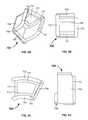
- FIGS. 3A through 3Dillustrate a perspective view, a front view, a side view, and a top view, respectively, of an assembled sliding intervertebral implant including the inner member of FIGS. 1A through 1D and the outer member of FIGS. 2A through 2D in a non-extended position according to an embodiment herein;
- FIGS. 4A through 4Dillustrate a perspective view, a front view, a side view, and a top view, respectively, of the assembled sliding intervertebral implant of FIGS. 3A through 3D in an extended position according to an embodiment herein;
- FIG. 5is a process flow diagram illustrating a method of performing a surgical procedure according to an embodiment herein.
- the embodiments hereinachieve this by providing a sliding intervertebral implant that attaches to a vertebral body, whereby the sliding intervertebral implant includes an inner member and an outer member that slide with respect to one another within a limitation of a pre-set curvature to an extended position, wherein the pre-set curvature is based on a pattern of an outer shape of the intervertebral space (i.e., space between vertebral bodies).
- FIGS. 1A through 1Dillustrate a perspective view, a front view, a side view, and a top view, respectively, of an inner member 600 of a sliding intervertebral implant 800 (as shown in FIGS. 3A through 4D ) according to an embodiment herein.
- the inner member 600includes a front wall 602 having a first rectangular gap 604 , a leg 605 connected to the front wall 602 and having an upper portion 606 and a lower portion 608 positioned opposite to the upper portion 606 .
- the inner member 600further includes a first curved side wall 610 having a second rectangular gap 612 , a second curved side wall 614 positioned opposite to the first curved side wall 610 and having a third rectangular gap 616 , a lower curved wall 618 , and an upper curved wall 620 .
- FIG. 1Ais a three dimensional perspective view of the inner member 600 .
- the first curved sidewall 610 having the second rectangular gap 612is coupled to the right side of the front wall 602 having the first rectangular gap 604 .
- the second curved side wall 614 having the third rectangular gap 616is coupled to the left side of the front wall 602 .
- the upper curved wall 620is coupled to the upper side of the front wall 602 and the lower curved wall 618 is coupled to the lower side of the front wall 602 .
- the length of the lower curved wall 618is smaller than that of the upper curved wall 620 thereby creating an overall arcuate shape for the inner member 600 .
- FIG. 1Ais a three dimensional perspective view of the inner member 600 .
- the first curved sidewall 610 having the second rectangular gap 612is coupled to the right side of the front wall 602 having the first rectangular gap 604 .
- the second curved side wall 614 having the third rectangular gap 616is coupled to the left side of
- FIG. 1Bis the front view of the inner member 600 , which illustrates the front wall 602 with the first rectangular gap 604 , and the leg 605 with the upper portion 606 and the lower portion 608 . Additionally, the upper portion 611 and lower portion 613 of the first curved side wall 610 is also shown having a height substantially equal to the height of the leg 605 .
- FIG. 1Cis the side view of the inner member 600 , which shows the first curved side wall 610 with the second rectangular gap 612 , the lower curved wall 618 , and the upper curved wall 620 .
- each of the lower curved wall 618 and the upper curved wall 620are longer than the first curved side wall 610 thereby creating a notch 615 in the first curved side wall 610 . Additionally, the height of the first curved side wall 610 is greater than the height defined by the distance between the lower curved wall 618 and the upper curved wall 620 .
- FIG. 1Dis the top view which shows the upper portion 606 of the leg 605 , the second curved sidewall 610 with the notch 615 , and the upper curved wall 620 .
- the first rectangular gap 604 , second rectangular gap 612 , and third rectangular gap 616permit bone and/or other materials (e.g., bone morphogenetic protein (BMP)) to be packed in the implant 800 (of FIGS. 4A through 4D ) once implanted in the human body.
- BMPbone morphogenetic protein
- FIGS. 2A through 2Dillustrate a perspective view, a front view, a side view, and a top view, respectively, of the outer member 700 according to an embodiment herein.
- the outer member 700forms a component of the sliding intervertebral implant 800 (as shown in FIGS. 3A through 4D ).
- the outer member 700includes a top curved wall 702 , a bottom curved wall 704 , an inclined side wall 706 , a back wall 708 , and a guide wall 710 having a rectangular gap 712 and two grooves 714 , 716 .
- FIG. 2Ais the three dimensional perspective view of the outer member 700 .
- the outer member 700generally has an open geometry as the inclined side wall 706 is truncated.
- FIG. 2Bis the front view of the outer member 700 , which shows the top curved wall 702 , the bottom curved wall 704 , the inclined side wall 706 , the back wall 708 , and the third sidewall 710 .
- FIG. 2Cis the side view of the outer member 700 , which illustrates the top curved wall 702 , the bottom curved wall 704 , the inclined side wall 706 , and the guide wall 710 having the rectangular gap 712 and the two grooves 714 , 716 .
- the length of the top curved wall 702is longer than the length of the bottom curved wall 704 to create an arcuate shape to the outer member 700 .
- the length of each of the top curved wall 702 and the bottom curved wall 704is larger than the length of the guide wall 710 .
- FIG. 2Dis the top view of the outer member 700 , which shows the upper side of top curved wall 702 , the inclined side wall 706 , and the guide wall 710 .
- the rectangular gap 712permits bone and/or other materials (e.g., bone morphogenetic protein (BMP)) to be packed in the implant 800 (of FIGS. 4A through 4D ) once implanted in the human body.
- BMPbone
- FIGS. 3A through 3Dillustrate a perspective view, a front view, a side view, and a top view respectively of a sliding intervertebral implant 800 having the inner member 600 and the outer member 700 in a non-extended position according to an embodiment herein.
- FIG. 3Ais the perspective view of the sliding intervertebral implant 800 .
- the inner member 600 and the outer member 700are shown interconnected with each other.
- the top curved wall 702 and the bottom curved wall 704 of the outer member 700accommodate the inner member 600 .
- the first curved side wall 610is attached with the inclined side wall 706 .
- FIG. 3Ais the front view of the sliding intervertebral implant 800 .
- the top curved wall 702 and the bottom curved wall 704are fixed over the upper curved wall 620 and the lower curved wall 618 of FIGS. 1A and 1C .
- FIG. 3Cis the side view of the sliding intervertebral implant 800 .
- the first curved side wall 610is connected to the inclined side wall 706 .
- FIG. 3Dis the top view.
- the first leg 606 and the first curved side wall 610 of the inner member 600are connected to the guide wall 710 and the inclined side wall 706 of the outer member 700 .
- the inner member 600 and the outer member 700 of the sliding intervertebral implant 800have open geometries for accommodating more surface contact. When the sliding intervertebral implant 800 is inserted into the intervertebral space, the inner member 600 and the outer member 700 remain in the non-extended position; however the members 600 , 700 may slide with respect to one another after insertion to sustain forces from the adjacent vertebrae.
- the insertioncan be performed by placing a long-extendable insertion device (not shown) in the second rectangular gap 612 . After the insertion, the insertion device will slide down to position the outer member 700 . Another option is that the insertion device holds the front wall 602 in place. After the insertion, the extendable portion of the insertion device pushes the outer member 700 into the desired position.
- FIGS. 4A through 4Dillustrate a perspective view, a front view, a side view, and a top view, respectively, of the sliding intervertebral implant 800 of having the inner member 600 and the outer member 700 in an extendable position according to an embodiment herein.
- FIG. 4Ais the perspective view of the sliding intervertebral implant 800 .
- both the inner 600 and the outer member 700are in their fully extended positions.
- the inner member 600slides through the outer member 700 in an arcuate path by the help of the first curved side wall 610 , which along with the upper curved wall 620 slides into the outer member 700 .
- FIG. 4Cis the side view of the sliding intervertebral implant 800 .
- the upper curved wall 620 and the lower curved wall 618 of the inner member 600slide into the outer member 700 by the help of the grooves 714 and 716 .
- the curved shape of the first curved side wall 610 of the inner member 600matches with the curved shape of the top curved wall 702 and the bottom curved wall 704 of the outer member 700 .
- FIG. 4Dis the top view illustrating the top curved wall 702 of the outer member 700 sliding over the upper curved wall of the inner member 600 .
- the final surface contact of the implant 800does not change (e.g., may remain in the non-extended position of FIGS. 3A through 3D ).
- the inner member 600may fully slide and form an extended position such as an arced structure.
- This arced structuremay increase a length of supporting surface between two adjacent vertebrae by increasing a length of the intervertebral implant 800 .
- insertse.g. bone, morphogenetic protein (BMP), etc
- BMPmorphogenetic protein
- pinning meansmay be applied to the implant 800 to ensure that the inner member 600 is not longitudinally disengaged from the outer member 700 .
- the pinning meansmay include a clamp, a pin, a screw, or any other known mechanism suitable for retaining the inner member 600 to the outer member 700 .
- the inclined side wall 706 of the outer member 700prevents the inner member 600 from laterally disengaging from the outer member 700 .
- FIG. 5is a process flow that illustrates a method of performing a surgical procedure according to an embodiment herein, wherein the method comprises engaging ( 501 ) an intervertebral sliding implant in a non-extended position to a vertebral body, wherein the intervertebral sliding implant 800 comprises a first member 600 adapted to connect to an intervertebral space (not shown) between two adjacent vertebrae (not shown), wherein the first member 600 has a curved configuration and comprises a pair of curved side walls 610 , 614 connected to each of a front wall 602 , an upper curved wall 620 , and a lower curved wall 618 , wherein a length of a first curved side wall 610 is less than a length of each of a second curved side wall 614 , the upper curved wall 620 , and the lower curved wall 618 , and wherein an edge of the second curved side wall 614 is offset from an edge of the
- the implant 800further includes a second member 700 slidably attached to the first member 600 , wherein the second member 700 has a curved configuration and comprises a top 702 and bottom 704 curved wall each connected to a truncated inclined side wall 706 and a guide wall 710 positioned opposite to the truncated inclined side wall 706 , wherein the guide wall 710 comprises a plurality of oppositely positioned grooves 714 , 716 .
- the methodfurther comprises adjusting ( 503 ) the inner member 600 according to the intervertebral space (not shown) of the vertebral body (not shown); aligning ( 505 ) the second curved side wall 614 of the first member 600 in the plurality of grooves 714 , 716 of the second member 700 ; and sliding ( 507 ) the second curved side wall 614 of the first member 600 in the plurality of grooves 714 , 716 of the second member 700 within a limitation of a pre-set curvature to an extended position, wherein the pre-set curvature is based on a pattern of an outer shape of the intervertebral space (not shown).
- the front wall 602comprises a leg 605 positioned along an edge of the front wall 602 adjacent to the second curved side wall 614 , and wherein a height of the leg 605 of the front wall 602 is substantially equal to a height of the first curved side wall 610 .
- the height of each of the leg 605 of the front wall 602 and the first curved side wall 610may be greater than a height of each of the front wall 602 and the second curved side wall 614 .
- first member 600 and the second member 700may be adapted to articulate from an extended position to a non-extended position as the first member 600 slides into the second member 700 , and wherein the first curved side wall 610 of the first member 600 is adapted to connect to the truncated inclined side wall 706 of the second member 700 in the non-extended position.
- each of the front wall 602 , the first curved side wall 610 , and the second curved side wall 614 of the first member 600comprise a gap 604 , 612 , 616 , respectively, wherein the method may further comprise inserting bone fusion material in the sliding intervertebral implant 800 through each the gap 604 , 612 , 616 in the non-extended position.
Landscapes
- Health & Medical Sciences (AREA)
- Engineering & Computer Science (AREA)
- Biomedical Technology (AREA)
- Neurology (AREA)
- Orthopedic Medicine & Surgery (AREA)
- Cardiology (AREA)
- Oral & Maxillofacial Surgery (AREA)
- Transplantation (AREA)
- Heart & Thoracic Surgery (AREA)
- Vascular Medicine (AREA)
- Life Sciences & Earth Sciences (AREA)
- Animal Behavior & Ethology (AREA)
- General Health & Medical Sciences (AREA)
- Public Health (AREA)
- Veterinary Medicine (AREA)
- Prostheses (AREA)
Abstract
Description
Claims (20)
Priority Applications (2)
| Application Number | Priority Date | Filing Date | Title |
|---|---|---|---|
| US11/869,798US7850734B2 (en) | 2007-10-10 | 2007-10-10 | Sliding intervertebral implant |
| US12/938,922US8273128B2 (en) | 2007-10-10 | 2010-11-03 | Sliding intervertebral implant method |
Applications Claiming Priority (1)
| Application Number | Priority Date | Filing Date | Title |
|---|---|---|---|
| US11/869,798US7850734B2 (en) | 2007-10-10 | 2007-10-10 | Sliding intervertebral implant |
Related Child Applications (1)
| Application Number | Title | Priority Date | Filing Date |
|---|---|---|---|
| US12/938,922DivisionUS8273128B2 (en) | 2007-10-10 | 2010-11-03 | Sliding intervertebral implant method |
Publications (2)
| Publication Number | Publication Date |
|---|---|
| US20090099659A1 US20090099659A1 (en) | 2009-04-16 |
| US7850734B2true US7850734B2 (en) | 2010-12-14 |
Family
ID=40534985
Family Applications (2)
| Application Number | Title | Priority Date | Filing Date |
|---|---|---|---|
| US11/869,798Expired - Fee RelatedUS7850734B2 (en) | 2007-10-10 | 2007-10-10 | Sliding intervertebral implant |
| US12/938,922Expired - Fee RelatedUS8273128B2 (en) | 2007-10-10 | 2010-11-03 | Sliding intervertebral implant method |
Family Applications After (1)
| Application Number | Title | Priority Date | Filing Date |
|---|---|---|---|
| US12/938,922Expired - Fee RelatedUS8273128B2 (en) | 2007-10-10 | 2010-11-03 | Sliding intervertebral implant method |
Country Status (1)
| Country | Link |
|---|---|
| US (2) | US7850734B2 (en) |
Cited By (18)
| Publication number | Priority date | Publication date | Assignee | Title |
|---|---|---|---|---|
| US20100256764A1 (en)* | 2009-04-01 | 2010-10-07 | Industrial Technology Research Institute | Spinal cage and implanting method thereof |
| US8147554B2 (en)* | 2008-10-13 | 2012-04-03 | Globus Medical, Inc. | Intervertebral spacer |
| US8801793B2 (en) | 2011-01-18 | 2014-08-12 | Warsaw Orthopedic, Inc. | Interbody containment implant |
| USD731061S1 (en) | 2012-11-28 | 2015-06-02 | Nuvasive, Inc. | Intervertebral implant |
| US20150265422A1 (en)* | 2011-07-14 | 2015-09-24 | Nlt Spine Ltd. | Laterally Deflectable Implant |
| US9198765B1 (en) | 2011-10-31 | 2015-12-01 | Nuvasive, Inc. | Expandable spinal fusion implants and related methods |
| US9216096B2 (en) | 2010-03-16 | 2015-12-22 | Pinnacle Spine Group, Llc | Intervertebral implants and related tools |
| US9380932B1 (en) | 2011-11-02 | 2016-07-05 | Pinnacle Spine Group, Llc | Retractor devices for minimally invasive access to the spine |
| US9445918B1 (en) | 2012-10-22 | 2016-09-20 | Nuvasive, Inc. | Expandable spinal fusion implants and related instruments and methods |
| US9468536B1 (en) | 2011-11-02 | 2016-10-18 | Nuvasive, Inc. | Spinal fusion implants and related methods |
| US9820865B2 (en) | 2013-10-31 | 2017-11-21 | Nlt Spine Ltd. | Adjustable implant |
| US10070970B2 (en) | 2013-03-14 | 2018-09-11 | Pinnacle Spine Group, Llc | Interbody implants and graft delivery systems |
| US10149770B2 (en) | 2013-07-09 | 2018-12-11 | Seaspine, Inc. | Orthopedic implant with adjustable angle between tissue contact surfaces |
| USD847339S1 (en) | 2017-06-26 | 2019-04-30 | Advanced Research System, LLC | Spinal fusion cage |
| US10492923B2 (en) | 2014-06-25 | 2019-12-03 | Seaspine, Inc. | Expanding implant with hinged arms |
| USD879295S1 (en) | 2017-02-13 | 2020-03-24 | Advance Research System, Llc | Spinal fusion cage |
| US11058551B2 (en) | 2016-12-16 | 2021-07-13 | Advance Research System, Llc | Interbody implant with concave profiled nose |
| US11737888B1 (en) | 2019-09-19 | 2023-08-29 | Advance Research System, Llc | Spinal fusion implant system and method |
Families Citing this family (52)
| Publication number | Priority date | Publication date | Assignee | Title |
|---|---|---|---|---|
| US6793678B2 (en) | 2002-06-27 | 2004-09-21 | Depuy Acromed, Inc. | Prosthetic intervertebral motion disc having dampening |
| AU2004212942A1 (en) | 2003-02-14 | 2004-09-02 | Depuy Spine, Inc. | In-situ formed intervertebral fusion device |
| US20040267367A1 (en) | 2003-06-30 | 2004-12-30 | Depuy Acromed, Inc | Intervertebral implant with conformable endplate |
| US8636802B2 (en) | 2004-03-06 | 2014-01-28 | DePuy Synthes Products, LLC | Dynamized interspinal implant |
| WO2008070863A2 (en) | 2006-12-07 | 2008-06-12 | Interventional Spine, Inc. | Intervertebral implant |
| US8900307B2 (en) | 2007-06-26 | 2014-12-02 | DePuy Synthes Products, LLC | Highly lordosed fusion cage |
| EP2237748B1 (en) | 2008-01-17 | 2012-09-05 | Synthes GmbH | An expandable intervertebral implant |
| US8936641B2 (en) | 2008-04-05 | 2015-01-20 | DePuy Synthes Products, LLC | Expandable intervertebral implant |
| US9526620B2 (en) | 2009-03-30 | 2016-12-27 | DePuy Synthes Products, Inc. | Zero profile spinal fusion cage |
| KR101687435B1 (en) | 2009-07-06 | 2016-12-19 | 신세스 게엠바하 | Expandable fixation assemblies |
| US8840668B1 (en) | 2009-11-11 | 2014-09-23 | Nuvasive, Inc. | Spinal implants, instruments and related methods |
| US8740983B1 (en) | 2009-11-11 | 2014-06-03 | Nuvasive, Inc. | Spinal fusion implants and related methods |
| US9393129B2 (en) | 2009-12-10 | 2016-07-19 | DePuy Synthes Products, Inc. | Bellows-like expandable interbody fusion cage |
| US9421109B2 (en) | 2010-01-13 | 2016-08-23 | Jcbd, Llc | Systems and methods of fusing a sacroiliac joint |
| US9333090B2 (en) | 2010-01-13 | 2016-05-10 | Jcbd, Llc | Systems for and methods of fusing a sacroiliac joint |
| CA3002234C (en) | 2010-01-13 | 2020-07-28 | Jcbd, Llc | Sacroiliac joint fixation fusion system |
| WO2014015309A1 (en) | 2012-07-20 | 2014-01-23 | Jcbd, Llc | Orthopedic anchoring system and methods |
| US9381045B2 (en) | 2010-01-13 | 2016-07-05 | Jcbd, Llc | Sacroiliac joint implant and sacroiliac joint instrument for fusing a sacroiliac joint |
| US9907560B2 (en) | 2010-06-24 | 2018-03-06 | DePuy Synthes Products, Inc. | Flexible vertebral body shavers |
| US8979860B2 (en) | 2010-06-24 | 2015-03-17 | DePuy Synthes Products. LLC | Enhanced cage insertion device |
| US8623091B2 (en) | 2010-06-29 | 2014-01-07 | DePuy Synthes Products, LLC | Distractible intervertebral implant |
| US20120078372A1 (en) | 2010-09-23 | 2012-03-29 | Thomas Gamache | Novel implant inserter having a laterally-extending dovetail engagement feature |
| US9402732B2 (en) | 2010-10-11 | 2016-08-02 | DePuy Synthes Products, Inc. | Expandable interspinous process spacer implant |
| US9248028B2 (en) | 2011-09-16 | 2016-02-02 | DePuy Synthes Products, Inc. | Removable, bone-securing cover plate for intervertebral fusion cage |
| EP2877127B1 (en) | 2012-07-26 | 2019-08-21 | Synthes GmbH | Expandable implant |
| US9717601B2 (en) | 2013-02-28 | 2017-08-01 | DePuy Synthes Products, Inc. | Expandable intervertebral implant, system, kit and method |
| US9522070B2 (en) | 2013-03-07 | 2016-12-20 | Interventional Spine, Inc. | Intervertebral implant |
| US10433880B2 (en) | 2013-03-15 | 2019-10-08 | Jcbd, Llc | Systems and methods for fusing a sacroiliac joint and anchoring an orthopedic appliance |
| WO2014146018A1 (en) | 2013-03-15 | 2014-09-18 | Jcbd, Llc | Systems and methods for fusing a sacroiliac joint and anchoring an orthopedic appliance |
| US9717539B2 (en) | 2013-07-30 | 2017-08-01 | Jcbd, Llc | Implants, systems, and methods for fusing a sacroiliac joint |
| US10245087B2 (en) | 2013-03-15 | 2019-04-02 | Jcbd, Llc | Systems and methods for fusing a sacroiliac joint and anchoring an orthopedic appliance |
| US9826986B2 (en) | 2013-07-30 | 2017-11-28 | Jcbd, Llc | Systems for and methods of preparing a sacroiliac joint for fusion |
| USD745159S1 (en) | 2013-10-10 | 2015-12-08 | Nuvasive, Inc. | Intervertebral implant |
| US9801546B2 (en) | 2014-05-27 | 2017-10-31 | Jcbd, Llc | Systems for and methods of diagnosing and treating a sacroiliac joint disorder |
| USD858769S1 (en) | 2014-11-20 | 2019-09-03 | Nuvasive, Inc. | Intervertebral implant |
| US11426290B2 (en) | 2015-03-06 | 2022-08-30 | DePuy Synthes Products, Inc. | Expandable intervertebral implant, system, kit and method |
| US9913727B2 (en) | 2015-07-02 | 2018-03-13 | Medos International Sarl | Expandable implant |
| EP3474784A2 (en) | 2016-06-28 | 2019-05-01 | Eit Emerging Implant Technologies GmbH | Expandable and angularly adjustable intervertebral cages with articulating joint |
| US11510788B2 (en) | 2016-06-28 | 2022-11-29 | Eit Emerging Implant Technologies Gmbh | Expandable, angularly adjustable intervertebral cages |
| US10258483B2 (en)* | 2016-08-19 | 2019-04-16 | Degen Medical, Inc. | Laminate implantable medical devices |
| US10537436B2 (en) | 2016-11-01 | 2020-01-21 | DePuy Synthes Products, Inc. | Curved expandable cage |
| US10888433B2 (en) | 2016-12-14 | 2021-01-12 | DePuy Synthes Products, Inc. | Intervertebral implant inserter and related methods |
| US10398563B2 (en) | 2017-05-08 | 2019-09-03 | Medos International Sarl | Expandable cage |
| US11344424B2 (en) | 2017-06-14 | 2022-05-31 | Medos International Sarl | Expandable intervertebral implant and related methods |
| US10940016B2 (en) | 2017-07-05 | 2021-03-09 | Medos International Sarl | Expandable intervertebral fusion cage |
| US11801144B2 (en) | 2017-09-14 | 2023-10-31 | Degen Medical, Inc. | Methods of making medical devices |
| US10603055B2 (en) | 2017-09-15 | 2020-03-31 | Jcbd, Llc | Systems for and methods of preparing and fusing a sacroiliac joint |
| US11446156B2 (en) | 2018-10-25 | 2022-09-20 | Medos International Sarl | Expandable intervertebral implant, inserter instrument, and related methods |
| US11426286B2 (en) | 2020-03-06 | 2022-08-30 | Eit Emerging Implant Technologies Gmbh | Expandable intervertebral implant |
| US11850160B2 (en) | 2021-03-26 | 2023-12-26 | Medos International Sarl | Expandable lordotic intervertebral fusion cage |
| US11752009B2 (en) | 2021-04-06 | 2023-09-12 | Medos International Sarl | Expandable intervertebral fusion cage |
| US12090064B2 (en) | 2022-03-01 | 2024-09-17 | Medos International Sarl | Stabilization members for expandable intervertebral implants, and related systems and methods |
Citations (7)
| Publication number | Priority date | Publication date | Assignee | Title |
|---|---|---|---|---|
| US6773460B2 (en) | 2000-12-05 | 2004-08-10 | Roger P. Jackson | Anterior variable expandable fusion cage |
| US6830589B2 (en) | 1999-06-23 | 2004-12-14 | Zimmer Spine, Inc. | Expandable fusion device and method |
| US6893464B2 (en) | 2002-03-05 | 2005-05-17 | The Regents Of The University Of California | Method and apparatus for providing an expandable spinal fusion cage |
| US7018415B1 (en) | 2002-09-23 | 2006-03-28 | Sdgi Holdings, Inc. | Expandable spinal fusion device and methods of promoting spinal fusion |
| US7083650B2 (en) | 2004-05-13 | 2006-08-01 | Moskowitz Nathan C | Artificial expansile total lumbar and thoracic discs for posterior placement without supplemental instrumentation and its adaptation for anterior placement of artificial cervical, thoracic and lumbar discs |
| US7094257B2 (en) | 2003-02-14 | 2006-08-22 | Zimmer Spine, Inc. | Expandable intervertebral implant cage |
| US7217293B2 (en) | 2003-11-21 | 2007-05-15 | Warsaw Orthopedic, Inc. | Expandable spinal implant |
Family Cites Families (2)
| Publication number | Priority date | Publication date | Assignee | Title |
|---|---|---|---|---|
| US5290312A (en)* | 1991-09-03 | 1994-03-01 | Alphatec | Artificial vertebral body |
| US6648917B2 (en) | 2001-10-17 | 2003-11-18 | Medicinelodge, Inc. | Adjustable bone fusion implant and method |
- 2007
- 2007-10-10USUS11/869,798patent/US7850734B2/ennot_activeExpired - Fee Related
- 2010
- 2010-11-03USUS12/938,922patent/US8273128B2/ennot_activeExpired - Fee Related
Patent Citations (7)
| Publication number | Priority date | Publication date | Assignee | Title |
|---|---|---|---|---|
| US6830589B2 (en) | 1999-06-23 | 2004-12-14 | Zimmer Spine, Inc. | Expandable fusion device and method |
| US6773460B2 (en) | 2000-12-05 | 2004-08-10 | Roger P. Jackson | Anterior variable expandable fusion cage |
| US6893464B2 (en) | 2002-03-05 | 2005-05-17 | The Regents Of The University Of California | Method and apparatus for providing an expandable spinal fusion cage |
| US7018415B1 (en) | 2002-09-23 | 2006-03-28 | Sdgi Holdings, Inc. | Expandable spinal fusion device and methods of promoting spinal fusion |
| US7094257B2 (en) | 2003-02-14 | 2006-08-22 | Zimmer Spine, Inc. | Expandable intervertebral implant cage |
| US7217293B2 (en) | 2003-11-21 | 2007-05-15 | Warsaw Orthopedic, Inc. | Expandable spinal implant |
| US7083650B2 (en) | 2004-05-13 | 2006-08-01 | Moskowitz Nathan C | Artificial expansile total lumbar and thoracic discs for posterior placement without supplemental instrumentation and its adaptation for anterior placement of artificial cervical, thoracic and lumbar discs |
Cited By (31)
| Publication number | Priority date | Publication date | Assignee | Title |
|---|---|---|---|---|
| US8147554B2 (en)* | 2008-10-13 | 2012-04-03 | Globus Medical, Inc. | Intervertebral spacer |
| US8840648B2 (en)* | 2009-04-01 | 2014-09-23 | Industrial Technology Research Institute | Spinal cage and implanting method thereof |
| US20100256764A1 (en)* | 2009-04-01 | 2010-10-07 | Industrial Technology Research Institute | Spinal cage and implanting method thereof |
| US9788973B2 (en) | 2010-03-16 | 2017-10-17 | Pinnacle Spine Group, Llc | Spinal implant |
| US9216096B2 (en) | 2010-03-16 | 2015-12-22 | Pinnacle Spine Group, Llc | Intervertebral implants and related tools |
| US9649203B2 (en) | 2010-03-16 | 2017-05-16 | Pinnacle Spine Group, Llc | Methods of post-filling an intervertebral implant |
| US8801793B2 (en) | 2011-01-18 | 2014-08-12 | Warsaw Orthopedic, Inc. | Interbody containment implant |
| US20150265422A1 (en)* | 2011-07-14 | 2015-09-24 | Nlt Spine Ltd. | Laterally Deflectable Implant |
| US10617530B2 (en) | 2011-07-14 | 2020-04-14 | Seaspine, Inc. | Laterally deflectable implant |
| US12029655B2 (en) | 2011-07-14 | 2024-07-09 | Seaspine, Inc. | Laterally deflectable implant |
| US9532884B2 (en) | 2011-07-14 | 2017-01-03 | Nlt Spine Ltd. | Laterally deflectable implant |
| US9655744B1 (en) | 2011-10-31 | 2017-05-23 | Nuvasive, Inc. | Expandable spinal fusion implants and related methods |
| US9198765B1 (en) | 2011-10-31 | 2015-12-01 | Nuvasive, Inc. | Expandable spinal fusion implants and related methods |
| US9380932B1 (en) | 2011-11-02 | 2016-07-05 | Pinnacle Spine Group, Llc | Retractor devices for minimally invasive access to the spine |
| US9468536B1 (en) | 2011-11-02 | 2016-10-18 | Nuvasive, Inc. | Spinal fusion implants and related methods |
| US10098753B1 (en) | 2011-11-02 | 2018-10-16 | Nuvasive, Inc. | Spinal fusion implants and related methods |
| US12048635B2 (en) | 2012-10-22 | 2024-07-30 | Nuvasive, Inc. | Expandable spinal fusion implant, related instruments and methods |
| US9445918B1 (en) | 2012-10-22 | 2016-09-20 | Nuvasive, Inc. | Expandable spinal fusion implants and related instruments and methods |
| US11399954B2 (en) | 2012-10-22 | 2022-08-02 | Nuvasive, Inc. | Expandable spinal fusion implant, related instruments and methods |
| US10350084B1 (en) | 2012-10-22 | 2019-07-16 | Nuvasive, Inc. | Expandable spinal fusion implant, related instruments and methods |
| USD731061S1 (en) | 2012-11-28 | 2015-06-02 | Nuvasive, Inc. | Intervertebral implant |
| US10070970B2 (en) | 2013-03-14 | 2018-09-11 | Pinnacle Spine Group, Llc | Interbody implants and graft delivery systems |
| US10149770B2 (en) | 2013-07-09 | 2018-12-11 | Seaspine, Inc. | Orthopedic implant with adjustable angle between tissue contact surfaces |
| US9820865B2 (en) | 2013-10-31 | 2017-11-21 | Nlt Spine Ltd. | Adjustable implant |
| US10492923B2 (en) | 2014-06-25 | 2019-12-03 | Seaspine, Inc. | Expanding implant with hinged arms |
| US11622866B2 (en) | 2014-06-25 | 2023-04-11 | Seaspine, Inc. | Expanding implant with hinged arms |
| US11058551B2 (en) | 2016-12-16 | 2021-07-13 | Advance Research System, Llc | Interbody implant with concave profiled nose |
| USD879295S1 (en) | 2017-02-13 | 2020-03-24 | Advance Research System, Llc | Spinal fusion cage |
| USD923178S1 (en) | 2017-02-13 | 2021-06-22 | Advance Research System, Llc | Spinal fusion cage |
| USD847339S1 (en) | 2017-06-26 | 2019-04-30 | Advanced Research System, LLC | Spinal fusion cage |
| US11737888B1 (en) | 2019-09-19 | 2023-08-29 | Advance Research System, Llc | Spinal fusion implant system and method |
Also Published As
| Publication number | Publication date |
|---|---|
| US20090099659A1 (en) | 2009-04-16 |
| US20110046738A1 (en) | 2011-02-24 |
| US8273128B2 (en) | 2012-09-25 |
Similar Documents
| Publication | Publication Date | Title |
|---|---|---|
| US7850734B2 (en) | Sliding intervertebral implant | |
| US20210298916A1 (en) | Expandable interbody implant | |
| US11696838B2 (en) | Systems and methods for inserting an expandable intervertebral device | |
| JP7057688B2 (en) | Dilating interbody implants and joint-driven inserters, and how to use them | |
| US7037339B2 (en) | Modular spinal fusion device | |
| ES2361377T3 (en) | SYSTEM TO RESTORE AND CONSERVE THE INTERVERTEBRAL ANATOMY. | |
| US8579976B2 (en) | Expandable cage for vertebral surgery involving lumbar intersomatic fusion by a transforaminal posterior approach | |
| JP5891231B2 (en) | Surgical graft with guide rail | |
| US10278831B2 (en) | Expandable intervertebral fusion device | |
| US20090093882A1 (en) | Sliding interbody device | |
| EP1372540B1 (en) | Intervertebral space implant for use in spinal fusion procedures | |
| US8778025B2 (en) | Rotatable cam lift for an expandable bone cage | |
| ES2350584T3 (en) | VERTEBRAL SURGERY SYSTEMS. | |
| CN1972647B (en) | Systems and techniques for restoring and maintaining intervertebral anatomy | |
| ES2300404T3 (en) | INTERSOMATIC CASE FOR BACK FUSION SURGERY OF THE LUMBAR COLUMN. | |
| EP3354233A1 (en) | Total ankle replacement prosthesis | |
| US20090149957A1 (en) | Modular lateral expansion device | |
| US20090182428A1 (en) | Flanged interbody device | |
| KR20080072757A (en) | Device for inserting prosthesis between intervertebral disc prosthesis and vertebra | |
| JP6817297B2 (en) | Expandable and adjustable interbody fusion devices and methods | |
| KR20200011636A (en) | Space expanding intervertebral fusion cage device | |
| JP7539277B2 (en) | Intervertebral implant and system including an intervertebral implant and an insertion device - Patents.com | |
| JP2022051708A (en) | Implant, insertion device for inserting implant, system of implant and insertion device, plate assembly for connecting with implant, system of implant and plate assembly, and kit comprising these |
Legal Events
| Date | Code | Title | Description |
|---|---|---|---|
| AS | Assignment | Owner name:CUSTOM SPINE, INC., NEW JERSEY Free format text:ASSIGNMENT OF ASSIGNORS INTEREST;ASSIGNORS:OH, YOUNGHOON;ABDELGANY, MAHMOUD F.;REEL/FRAME:019938/0248 Effective date:20071004 | |
| STCF | Information on status: patent grant | Free format text:PATENTED CASE | |
| FPAY | Fee payment | Year of fee payment:4 | |
| AS | Assignment | Owner name:EXWORKS ASSET HOLDINGS, LLC, ILLINOIS Free format text:ASSIGNMENT OF ASSIGNORS INTEREST;ASSIGNOR:CUSTOM SPINE, INC.;REEL/FRAME:036208/0526 Effective date:20150717 | |
| AS | Assignment | Owner name:CUSTOM SPINE ACQUISITION, INC., GEORGIA Free format text:ASSIGNMENT OF ASSIGNORS INTEREST;ASSIGNOR:EXWORKS ASSET HOLDINGS LLC;REEL/FRAME:037915/0959 Effective date:20160114 | |
| AS | Assignment | Owner name:ANTARES CAPITAL LP, AS AGENT, ILLINOIS Free format text:SECURITY INTEREST;ASSIGNOR:CUSTOM SPINE ACQUISITION, INC.;REEL/FRAME:038581/0722 Effective date:20160429 | |
| AS | Assignment | Owner name:CORTLAND CAPITAL MARKET SERVICES LLC, AS AGENT, IL Free format text:SECURITY INTEREST;ASSIGNOR:CUSTOM SPINE ACQUISITION, INC.;REEL/FRAME:038608/0230 Effective date:20160429 | |
| MAFP | Maintenance fee payment | Free format text:PAYMENT OF MAINTENANCE FEE, 8TH YR, SMALL ENTITY (ORIGINAL EVENT CODE: M2552) Year of fee payment:8 | |
| FEPP | Fee payment procedure | Free format text:MAINTENANCE FEE REMINDER MAILED (ORIGINAL EVENT CODE: REM.); ENTITY STATUS OF PATENT OWNER: SMALL ENTITY | |
| LAPS | Lapse for failure to pay maintenance fees | Free format text:PATENT EXPIRED FOR FAILURE TO PAY MAINTENANCE FEES (ORIGINAL EVENT CODE: EXP.); ENTITY STATUS OF PATENT OWNER: SMALL ENTITY | |
| STCH | Information on status: patent discontinuation | Free format text:PATENT EXPIRED DUE TO NONPAYMENT OF MAINTENANCE FEES UNDER 37 CFR 1.362 | |
| FP | Lapsed due to failure to pay maintenance fee | Effective date:20221214 | |
| AS | Assignment | Owner name:CUSTOM SPINE ACQUISITION, INC., CALIFORNIA Free format text:RELEASE BY SECURED PARTY;ASSIGNOR:CORTLAND CAPITAL MARKET SERVICES LLC, AS AGENT;REEL/FRAME:067605/0717 Effective date:20240531 Owner name:CUSTOM SPINE ACQUISITION, INC., CALIFORNIA Free format text:RELEASE BY SECURED PARTY;ASSIGNOR:ANTARES CAPITAL LP, AS ADMINISTRATIVE AGENT;REEL/FRAME:067605/0646 Effective date:20240531 |