US7850301B2 - Eyewear frames with magnetic lens attachements - Google Patents
Eyewear frames with magnetic lens attachementsDownload PDFInfo
- Publication number
- US7850301B2 US7850301B2US11/658,390US65839007AUS7850301B2US 7850301 B2US7850301 B2US 7850301B2US 65839007 AUS65839007 AUS 65839007AUS 7850301 B2US7850301 B2US 7850301B2
- Authority
- US
- United States
- Prior art keywords
- lens
- frame
- cavity
- magnets
- lenses
- Prior art date
- Legal status (The legal status is an assumption and is not a legal conclusion. Google has not performed a legal analysis and makes no representation as to the accuracy of the status listed.)
- Active, expires
Links
Images


Classifications
- G—PHYSICS
- G02—OPTICS
- G02C—SPECTACLES; SUNGLASSES OR GOGGLES INSOFAR AS THEY HAVE THE SAME FEATURES AS SPECTACLES; CONTACT LENSES
- G02C1/00—Assemblies of lenses with bridges or browbars
- G02C1/02—Bridge or browbar secured to lenses without the use of rims
- G—PHYSICS
- G02—OPTICS
- G02C—SPECTACLES; SUNGLASSES OR GOGGLES INSOFAR AS THEY HAVE THE SAME FEATURES AS SPECTACLES; CONTACT LENSES
- G02C1/00—Assemblies of lenses with bridges or browbars
- G02C1/04—Bridge or browbar secured to or integral with partial rims, e.g. with partially-flexible rim for holding lens
- G—PHYSICS
- G02—OPTICS
- G02C—SPECTACLES; SUNGLASSES OR GOGGLES INSOFAR AS THEY HAVE THE SAME FEATURES AS SPECTACLES; CONTACT LENSES
- G02C1/00—Assemblies of lenses with bridges or browbars
- G02C1/10—Special mounting grooves in the rim or on the lens
- G—PHYSICS
- G02—OPTICS
- G02C—SPECTACLES; SUNGLASSES OR GOGGLES INSOFAR AS THEY HAVE THE SAME FEATURES AS SPECTACLES; CONTACT LENSES
- G02C2200/00—Generic mechanical aspects applicable to one or more of the groups G02C1/00 - G02C5/00 and G02C9/00 - G02C13/00 and their subgroups
- G02C2200/02—Magnetic means
- G—PHYSICS
- G02—OPTICS
- G02C—SPECTACLES; SUNGLASSES OR GOGGLES INSOFAR AS THEY HAVE THE SAME FEATURES AS SPECTACLES; CONTACT LENSES
- G02C2200/00—Generic mechanical aspects applicable to one or more of the groups G02C1/00 - G02C5/00 and G02C9/00 - G02C13/00 and their subgroups
- G02C2200/08—Modular frames, easily exchangeable frame parts and lenses
Definitions
- the present inventionrelates to eyewear frames with magnetic lens attachments. More particularly, the present invention relates to eyeglass frames with interchangeable prescription or plano lenses and/or plano shields that can be interchanged by the user in a simple, and convenient manner and that are easily releasably attached to the frame.
- a typical pair of eyeglassesincludes a pair of lenses or a single shield mounted to a frame that may include rims around the lenses; a brow bar; a bridge piece connecting the inner ends of the rims; and two temple pieces attached to the outer ends of the rims for resting the glasses on the user.
- Lensesare typically mounted to the eyeglass frame by a screw or other fastening device that tightens the rim around the lens.
- the screwIn the conventional configuration, the screw must be removed before the lens may be removed.
- the screwis often small and identifying the size and type of screw can require the user to strain his or her eyes. Removing the screw requires that the user have a screw driver or other tool that fits the particular screw in that pair of eyewear. Users will often not have the proper screwdriver.
- the screwis broken or stripped, the user must then find a suitable replacement screw.
- An object of the present inventionis to provide a magnetic coupling system for eyeglass lenses. More specifically, it is an object of the present invention to provide an interchangeable magnetic lens system.
- a further object of the present inventionis to provide magnetic material attached to an eyeglass frame for releasably coupling lenses to the frame.
- Another object of the inventionis to provide magnets attached to the lenses for attracting to the magnetic forces of the magnetic material in the eyeglass frame.
- Yet another object of the inventionis to provide user-friendly and interchangeable magnetic lenses for eyeglasses.
- Still another object of the inventionis to provide various coupling methods for securing the magnetic lenses to the frames that have the magnetic material.
- Another object of the inventionis to allow the user to change their lenses easily, as opposed to relying on an optician or eyecare professional to change the lenses.
- Yet another object of the inventionis to provide interchangeable magnetic lenses or shields with different treatment tints or coatings.
- a single shield-type lens or a pair of interchangeable lensesthat may be placed in position in eyeglass frames using magnetic members to lock the respective lenses in place.
- the lensesmay be embedded with or otherwise support magnets or a magnetic material.
- the magnets or magnetic material in the lensesare attracted to corresponding magnets or magnetic material in a pair of eyeglass frames.
- the lenses and framesmay both be mounted with permanent magnets.
- either the lenses or the framemay have permanent magnets secured to one or the other, while the other of the lenses and the frame may have secured to it, or may be made of, magnetically attractive material, such as ferrous metal.
- the magnets or magnetic materialcan be positioned at various points of the frame and lens, such as in the annular areas or inner circumference of the frame and in the brow bar or nosepiece.
- the lensesare easily removable, providing a rapid and simple interchange of lenses.
- the magnets or magnetic material in the lensescan be mounted in a number of ways, including a 3-piece mounted frame, generally suitable for rimless frames. Another option is to provide a lens that fits into frames having a closed annular shelf with magnets on opposite sides, where the shelf prevents the lens from falling backwards out of the frame.
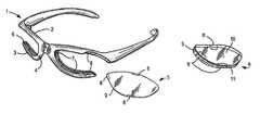
- FIG. 1 ais a front view of a pair of eyewear frames and detached lens, both comprising magnets according to a first embodiment of the invention
- FIG. 1 bis a front view of a lens with magnets or magnetic material embedded therein;
- FIG. 1 cis a side view of a lens having no magnets or magnetic material
- FIG. 1 dis a front view of a lens with magnets or magnetic material secured to the lens so that said magnets or magnetic material protrude beyond the edge of the lens;
- FIG. 2is a front view of a pair of eyewear frames, as seen in FIG. 1 , with the lenses mounted to the frame;
- FIGS. 3 a and 3 bare cross-sectional views of the eyewear frames, as seen in FIGS. 1 and 2 , at the point of magnetic attachment;
- FIG. 4is a front view of a ‘blade’-style frame with magnetic lenses
- FIGS. 5 a - 5 care front views of an alternative embodiment having magnets protruding from the top and nasal area of the lenses, which are received into pockets containing magnetic material on the horizontal arm and nose piece of the frame;
- FIG. 5 dis a cross-sectional view of a T-shaped magnetic attachment extending from the lens and received into a corresponding pocket of the frame, according to another embodiment of the present invention.
- FIG. 6 ais a perspective view of a pair of eyewear frames according to another embodiment of the invention.
- FIG. 6 bis a perspective view of a lens according to an embodiment of the invention.
- FIG. 6 cis a cross-section of the frame and lens of the embodiment shown in FIG. 6 a;
- FIG. 7is a front view of a partial eyewear frame having magnets glued into the rims according to all embodiments illustrated;
- FIGS. 8 a - 8 dare sectional views of magnets embedded in channels in the lens rims of frames in different embodiments of the present invention.
- FIGS. 9 a - 9 dare side views of magnets or magnetic material secured to various lenses
- FIGS. 10 a - 10 bare front views of an embodiment of the present invention in a blade-style frame
- FIG. 11 ais a front view of a semi-rimmed frame embodiment of the present invention.
- FIG. 11 bis a side view of portions of a partial rim, which were shown in FIG. 11 a , according to another embodiment of the present invention.
- FIG. 11 cis a front view of a lens, which was shown in FIG. 11 a , according to another embodiment of the present invention.
- FIG. 11 dis a side view of a lens, as shown in FIG. 11 c , according to an embodiment of the present invention.
- FIG. 11 eis a front view of a lens and partial rim, which were shown in FIG. 11 a , according to another embodiment of the present invention.
- FIGS. 12 a - 12 c ′show a three-piece-mount embodiment of the present invention
- FIG. 13is a front view of a magnetic rimlock closure embodiment of the present invention.
- FIGS. 14 a - 14 care front and side views of an embodiment of the present invention with a slide pin
- FIGS. 15 a - 15 hare front and side/sectional views of the various shapes of magnets possible with the various methods of attachment;
- FIG. 16 ais a perspective view of an embodiment of the present invention having a goggle-style frame and two shield-style lenses;
- FIG. 16 bis a cross-sectional view of an embodiment of the present invention having a goggle-style frame and two shield-style lenses;
- FIG. 16 cis a front view of a pair of lenses that could be combined with the embodiment shown in FIG. 16 a;
- FIG. 17 ais a front view of a lens with a wire surrounding its edge
- FIG. 17 bis a front view of a lens with a wire surrounding its edge and a magnet or magnetic material embedded in the lens;
- FIG. 17 cis a perspective view of a wire partially embedded in a groove in the edge of a lens.
- FIG. 17 dis a top view of the lens in FIG. 17 b.
- the term “lens”will be understood to include eyeglass lenses of a variety of shapes and sizes as well as one or more shield style lenses.
- the term “frame”will be understood to include blade-style frames, goggle-style frames, conventional frames, and any other style of eyewear frame.
- the term “plano lens”shall refer to lenses and shields that are not made to fill a wearer's prescription.
- the term “prescription lens”shall refer to lenses and shields that are made to fill a wearer's prescription as used in this description. “Plano lens” and “prescription lens” are used interchangeably throughout this specification.
- magnetsrefer to magnets or material that has magnetic properties or is capable of attracting a magnet. As such, “magnets,” “magnetic member,” “magnetized material,” and “magnetic material,” are interchangeable in this description.
- a “magnetic member” as used hereinis a component of an eyeglass assembly that is either a magnet or is made from magnetically attractive material.
- An “eyeglass assembly,” as used in this description,refers to an assembled pair of eyeglasses including a frame and at least one lens.
- FIG. 1 ashows an embodiment of the present invention.
- a pair of eyeglass frames 1includes at least one magnet or element of magnetically attractive material 7 embedded in the frame 1 .
- each side of the frame 1includes a portion of a rim 2 and 3 for supporting a lens 5 .
- Each rim portion 2 and 3includes a recess 6 into which a lens 5 may be received.
- the recess 6may extend toward the nosepiece 4 .
- Magnets or magnetically attractive material 7are embedded into the recesses 6 in the rim portions 2 and 3 of the frame 1 .
- at least one magnet or element of magnetically attractive material 7is located on each side in the recess 6 of the frame 1 that may receive a lens 5 .
- Magnets or magnetic material having opposing and attractive forces 8are attached to the corresponding ends of the eyeglass lenses 5 such that, when the lenses 5 are held close to the frames 1 , the attractive forces of the positively and negatively charged magnets pull the magnets 8 of the lenses 5 towards the magnets 7 of the frames 1 .
- the magnets 7are preferably embedded in the recess 6 of the frames 1 and the corresponding edge(s) 9 of each of the lenses 5 . This formation of the magnets provides a fully seated lens that is held in place through magnetic forces, as seen in FIG. 2 .
- FIG. 1 bshows a lens with magnets or magnetic material 8 embedded therein.
- a lens 5has a front surface 10 , a rear surface 11 and an edge 9 .
- FIG. 1 cshows a lens 5 laying on its rear surface 11 , with its edge 9 facing the reader, and its front surface 10 pointing toward the top of the page.
- the lens 5 in FIG. 1 cis similar to the lens in FIG. 1 b with no magnets or magnetic material embedded in the lens 5 .
- the magnets or magnetic material 8 secured to the lens 5lies flush with the edge 9 of the lens 5 .
- the magnets or magnetic material 8may be flush with the front 10 or rear 11 surfaces of the lens 5 .
- the lensmay cover the magnet or magnetic material as long as the magnet or magnetic material, when assembled, is sufficiently close to the corresponding magnets or magnetic material in the frame that the magnets or magnetic material in the frame and the lens attract one another.
- FIG. 1 dshows another lens according to the present invention. Magnets or magnetic material 8 protrude beyond the edge 9 of the lens 5 .
- FIG. 2shows a front view of an assembled eyeglass frame assembly according to an embodiment of the present invention.
- the frame 1contains magnets or magnetic material 7 embedded therein.
- the lens 5also contains magnets or magnetic material 8 embedded therein. The attractive forces between the magnets or magnetic material in the frame 7 and the magnets or magnetic material in the lenses 8 secure the lenses 5 to the frame 1 .
- the cross-sectional view of FIG. 3 adepicts the point of contact between the lens 5 and the frames 1 .
- the frames 1include a first 2 and a second 3 rim section.
- the first 2 and second 3 rim sectionshave a recess 6 for receiving the lens 5 .
- the recesses 6are shaped to fit the contour of the lens edges. Typically the recesses 6 are U-shaped, for receiving an end of a lens 5 .
- the nose piece 4may also have a recess and contain magnetic material. Magnets or magnetic material 8 are secured to the outside of the lens 5 , and are positioned near the magnets 7 in the frame 1 .
- the figureshows the front surface of the eyeglasses with the front surface of the lens 10 facing toward the reader. The location of the edge 9 of the lens 5 can also be seen in the cross-section.
- FIG. 3 billustrates a cross-section of the eyewear illustrated in FIG. 3 a , but with a first and a second magnet 8 embedded in the lens 5 .
- the magnetic lens 5is snugly fitted to the frame 1 so as to not accidentally eject during normal use of the frame 1 .
- the magnets or magnetically attractive materialmay be embedded in the lenses so as to be flush with the surface of the lenses.
- the lenseswould be received into a recess similar to that shown in FIGS. 1 a , 2 , 3 a , and 3 b , but without a lower rim section.
- FIG. 4shows another embodiment of the present invention. It is possible to attach lenses 5 containing magnets or magnetic material to ‘blade’-style frames 12 .
- a ‘blade’-style frame 12is a winged frame conventionally designed so that there are no rims surrounding the lower arcuate surfaces of the lenses 5 .
- a ‘blade’-style framelooks like a pair of lenses bordered by wings. Only the upper and nasal sections of the lenses 5 are engaged by the frame 12 .
- the points of contact between the frame 12 and the lenses 5comprise a first section of a recess located in the horizontal bridge portion 47 of the frame 12 and a second section of a recess located in the side wall adjacent to a nosepiece 4 .
- FIG. 5 ashows an embodiment of the present invention.
- the ‘blade’-style frame 12as seen in FIG. 4 , can receive lenses 5 in a recess 6 of the upper rim portion 2 of the frame 12 and in a recess 6 in the side wall adjacent the nosepiece 4 .
- the lens 5includes tabs 13 protruding from the edge of the lens 5 . Magnets or magnetic material may comprise or be attached to the tabs 13 .
- FIG. 5 bshows the same embodiment of the present invention as FIG. 5 a , with the lens in place in the frame.
- the frame 12has magnets 7 positioned in the recess of the upper rim portion 2 of the frame 12 and the nosepiece 4 .
- a lens 5is positioned in the frame 12 , preparing for the magnetic forces of the magnets or magnetic material embedded in the frame 7 and the magnets or magnetic material 8 embedded in the lens 5 to attract.
- the lens 5has been inserted upwards into the recess in the upper rim portion 2 of the frame 12 where the tabs are received.
- a second magnet embedded in a recess 6 in the upper rim portion 2 of the frame 12pulls the tab 13 up into place creating a slight mechanical stop, resisting the lens 5 from sliding out of the groove 6 .
- the lens 5is positioned into a recess 6 of the upper rim portion 2 of frame 12 and slid towards the nosepiece 4 . Once in this position, the attractive forces of the opposing magnets, positioned in the lens 5 and frame 12 , secure the lens 5 to the frame 12 . Additionally, the magnet in the lens 5 locks into the recess 6 and resists the lens 5 from dislodging out of the ‘blade’-style frame 12 .
- FIG. 5 dshows another embodiment of the present invention.
- the lens 5can comprise one magnet located at the portion of the lens 5 that attaches to the frame near the nasal area 4 and one mechanical “T” attachment 14 at the top.
- the frame 12has magnets 7 positioned in the upper rim portion 2 of the frame 12 and the nosepiece 4 .
- FIGS. 6 a - 6 cshow another embodiment of the present invention.
- the frame 1may include a full rim 21 encompassing a lens 5 .
- the lens 5must be inserted from either the front 15 or the back, as opposed to being slid into the frame 1 from the side as with the embodiment shown in FIGS. 1-3 .
- the frame 1does not have a channel-recess, but rather has a stepped interior surface 22 that provides a mechanical stop for the lens 5 when inserted, as shown in FIG. 6 c .
- the stepmay be a raised back wall so that the lens may only be removed through the front of the frame.
- the step 23may be a front wall so that the lens 5 may only be removed through the back of the frame 1 .
- the lens 5with embedded magnets 8 near the edge 9 , is inserted into a frame 1 with a raised front or back wall and positioned so that the magnets 8 of the lens 5 align with the magnets 7 in the frame 1 .
- the lenses 5are inserted from the front or back accordingly, and are held into place by the magnetic force of the magnets on both the frame 1 and lenses 5 .
- FIG. 7shows another embodiment of the present invention. Similar to the previously described embodiments, the magnets 7 can be secured to the frame 1 of the eyeglasses. Magnets or magnetic material 8 are also secured to the lens 5 . The magnets or magnetic material 7 secured to the frame 1 are embedded in a recess, so that they lie flush with the surface of the frame 1 . This allows the magnets or magnetic material 7 secured to the frame 1 to attract the magnets or magnetic material secured to the lens 5 , while allowing the lens 5 to fit flush to the frame 1 .
- the recess in the framedoes not need to span the length of the horizontal arm.
- Magnets protruding from the edge of the lenssuch as the magnets visible in FIG. 1 d , could be received in one or more recesses in the horizontal arm of a frame.
- magnets or magnetic materialcorresponding to the magnets or magnetic material protruding from the edge of the lens, could be secured inside of recesses in the horizontal arm of the frame that are contoured to fit the protrusions on the lens. The protrusions of the lens would then fit inside of these recesses in the horizontal arm of the frame.
- FIGS. 8 a - 8 fshow arrangements of magnets in the recesses of the frame.
- the recesscan be of any shape.
- a recess having a square shape 26 and a recess having a triangular shape 16are shown.
- rectangular magnets 7are positioned in a square-shaped recess 26 in a frame 1 so that a magnet is secured to each side of the recess.
- a rectangular magnet 7is positioned at the top of a square-shaped recess 26 . Rectangular magnets need not be used.
- FIG. 8 cshows a triangular-shaped magnet or magnets 18 secured to a frame having a triangular-shaped recess 16 .
- FIG. 8 dshows a triangular-shaped magnet 18 and recess 16 where the triangular shaped magnet 18 is not secured to all surfaces of the triangular-shaped recess 16 .
- the frame recesses in the rimsthere are many ways to configure the frame recesses in the rims to accept various types of lenses. There are even more possible ways to attach magnets to these different rim styles. The embodiments described are not intended to limit the combinations of magnetic placements and recesses in the rims.
- the horizontal arm of the framecould contain a protruding magnet or a protrusion with a magnet or magnetic material secured thereto and the lens may contain a recess with a magnet or magnetic material.
- magnetscan be secured to prescription or plano lenses.
- the lens 5 and the magnet 8are of equal thickness, however the magnets or magnetically attractive material secured to the lens may be thinner or thicker than the lens. Additionally, the magnets or magnetically attractive material may be a thin plate that is form-fitted into a shallow indentation in the edge of the lenses as shown in FIG. 9 b.
- magnets 8it is also possible to press-fit the magnets 8 to lenses 5 having a notched surface, such as the lens 5 in FIG. 9 c .
- the notched surface of the lens 5is covered with a magnet that can be pressed over the lens 5 to create a corresponding surface for attaching the lens 5 to a frame.
- a magnet having a similar shapecan be attached to a frame having a similar shape as this lens.
- Magnetscan be positioned on any side of the frame or recess and can be of any suitable shape. Magnets 8 can be attached to lenses having arcuate surfaces, such as the lens 5 in FIG. 9 a . Magnets can also be attached to lenses having notches 19 that project away from the arcuate surface, such as the lens 5 in FIG. 9 b . In either respect, the magnets are attached to the substantially arcuate portions of the lenses, not the notched portions. There is preferably a first magnet attached to the upper surface of the frame and a second magnet attached to the interim surface, close to the nosepiece. More than one magnet can be attached to either the lens or the frame.
- FIG. 10 ashows a front view of another embodiment of the present invention.
- a lens 5is secured to a frame 1 .
- Magnets or magnetic material 8 secured to the lens 5attracts magnets or magnetic material 7 secured to the frame 1 .
- the magnets or magnetic material 7 secured to the frame 1are recessed in a channel in the frame 1 so that the magnets or magnetic material lie flush with the surface of the frame 1 and the top of the lens 5 .
- FIG. 10 bshows a front view of another embodiment of the present invention.
- a lens 5is secured to a frame 1 .
- Magnets or magnetic material 8 secured to the lens 5attracts magnets or magnetic material 7 secured to the frame 1 .
- the magnets or magnetic material 7 secured to the frame 1are recessed in a channel in the frame 1 so that the magnets lie flush with the surface of the frame 1 and the top of the lens 5 .
- a notch 46 cut in the lens 5is received in a similarly shaped recess in the frame 1 and assists in securing the lens 5 to the frame 1 .
- FIGS. 11 a - 11 eAnother type of eyeglass frame that benefits from attaching magnetic lenses 5 to a frame having magnetic surfaces is the semi-rimmed frame 27 , as illustrated in FIGS. 11 a - 11 e .
- the frames 27are typically metal rims 28 with substantially arcuate surfaces corresponding to the lower halves of the lenses 5 , as seen in FIG. 11 a . Only the lower portions of the lenses 5 and parts of the sides of the lenses 5 are covered by the frame 27 . The remainder of the lens 5 , the upper substantially arcuate surface, is rimless.
- this embodimentis not only limited to the lower portion of the lens being covered by the frame, but may include other partial sections of the lens, such as the top half of the lens covered by frame.
- magnets 7are embedded in the side surfaces 29 of the rims 28 , towards the corners of the lenses 5 , as shown in FIG. 11 b and 11 c .
- the lens 5could similarly be attached to the semi-rimmed frame by embedding magnets in the portion of the rim 28 encompassing the bottom surfaces of the lenses 5 and securing corresponding magnets 8 in the bottom portion of the lenses 5 .
- Magnets, or magnetic material, 8are attached to the edges 9 of the lenses 5 , as shown in FIG. 11 c , to match the corresponding bevel of the frame, as shown in FIG. 11 b (square groove, substantially v-shaped groove, or round wire).
- the metal or molded wire of the eyeglass frames 27is typically constructed from a square groove, a substantially v-shaped groove, or a round wire, also illustrated in FIG. 11 b .
- FIG. 11 eshows a front view of the lens and the semi-rimmed frame of FIG. 11 a disassembled.
- FIGS. 12 a - 12 c ′another type of magnetic attachment, illustrated in FIGS. 12 a - 12 c ′, is associated with the three-piece mount, also referred to as a rimless mount.
- the three-piece mountinvolves a frame constructed without rims or eye wires.
- the three-piece mounthas three pieces: the bridge bar 32 , the temple or endpieces 31 , and the lenses 5 .
- Rimless mountstypically include two lenses 5 connected with a bridge bar 32 that attaches to the inner edge of the lenses 5 , and temple or endpieces 31 that are attached to the outer edge of the lenses 5 .
- the magnets in a three-piece mountlink the three pieces to each other.
- the bridge bar 32connects to the inner comers and/or edges of the lenses 5
- the temple or endpieces 31connect to the outer corners or edges of the lenses 5 .
- the magnets 8 secured to the lenses 5 in the three-piece mount embodiment shown in FIGS. 12 a - 12 bare attached to areas of each lens 5 defined by first and second indentations, collectively 30 , on the front and rear surfaces at the inner and outer comers of the lenses 5 .
- the magnets 8are located directly between the first and second indentations, towards the inner and outer layers of the lens, as seen in FIGS. 12 a and 12 b , so as to attract the magnetic surfaces 7 of the frame pieces.
- FIG. 12 bThe preferred method of attaching the lenses 5 to the bridge bar 32 is illustrated in FIG. 12 b , where the magnets secured to the bridge bar 33 are located in the slot 48 of the bridge bar 32 , furthest from the edge of the bridge bar 32 .
- This slot 48will preferably be closest to the inner corners of the lenses 5 when the forces of the magnets in the bridge bar 33 pull the opposing magnets in the inner comers of the lenses 8 towards the bridge bar magnets 33 .
- the attractive forces of the magnetsincrease when the magnets are close to each other and prevent the three-piece mount from unlinking.
- the lenses 5can be encompassed by metal around the edge of the lens, with at least one magnet located in the bridge bar 32 only. In such an embodiment, there is no need for magnetic members in the temple pieces.
- the bridge bar 32can be metal with at least one magnet secured to the lens 5 .
- each temple or endpiece and bridge bar 32includes a magnet or magnetic material 33 , on a first end, closest to the outer corner or edge of each lens 5 .
- the magnets attached to the temple or endpieces 31 or bridge bar 32protrude towards the outer corners of the lenses 5 for attracting the corresponding magnets embedded in the lenses 5 .
- This reactionis similar to the reaction between the magnets in the bridge bar and the magnets at the inner corners of the lenses 5 .
- This variationcan also be achieved in the opposite direction, with the magnet or protrusion in the rear of the lens 5 .
- the magnets or magnetic material 33 in the temple endpieces 31it is possible for the magnets or magnetic material 33 in the temple endpieces 31 to be positioned at the base of the endpieces 31 , towards the furthest end of the slot 48 with respect to the lenses 5 .
- Lenses 5have magnets 8 attached to the outermost edge of the recess towards the endpiece.
- magnets 8 and 33pull themselves together, securing lenses 5 into endpieces 31 .
- a complimentary configurationcan be at the bridge and lens locations, 32 and 30 .
- the magnets 33are positioned on either the upper or lower portion of the recess, towards the first end, closest to the lenses 5 .
- FIG. 13Another embodiment of the invention is a magnetic rimlock closure, illustrated in FIG. 13 .
- magnets 35are secured to the rims 36 of the frames 34 in the distal comers, at the side opposite the brow bar.
- the magnetsare attached at the site where the frames 34 are generally locked—the rimlock. This is also the location where the temple pieces 37 are connected to the rims 36 .
- the magnetreplaces the screw as the locking feature.
- the upper and lower sections of the frameseparate at the temple corners.
- a screwconnects the upper and lower sections.
- the magnets 35are applied to the ends of the frames 34 .
- the magnetic rimlockeliminates the need for a screw to lock the frames 34 at this junction because the magnetic forces secure the ends of the frame. Since the magnets 35 are attached to both ends of the frame, it is possible to use this magnetic rimlock method with frames of any suitable shape, including, but not limited to, a round or v-shaped eye wire. In this embodiment, it is not necessary that the lenses have magnets embedded therein. The lenses may be received in a recess in the rims of the frames 34 and held securely in place upon the closing and magnetic locking of the rimlock. Persons of skill in the art will appreciate that the rimlock can also be at the nasal bridge portion of the frame and not only at the temple or endpiece portion of the frame.
- FIGS. 14 a - cAnother embodiment of the magnetic attachment method of the present invention is the combination of a magnet with a non-magnetic pin 38 as illustrated in FIGS. 14 a - c . It is possible to attach a non-magnetic pin 38 to the upper substantially arcuate surface of the lens, as seen in FIG. 14 a . This pin 38 would be received in a frame 1 having a slot 39 or channel, such as the frame 1 in FIG. 14 c .
- the lens 5is supplied with a magnet 8 on its inner surface, closest to the brow bar, for coupling to a magnet embedded in the frame 1 .
- the lens 5is also secured to the frame 1 with a slide pin 38 , as seen in FIG. 14 c , which moves into a slot 39 in the frame 1 for securing the lens 5 .
- the pin 38can be a substantially T-shaped pin that would lock into place when the lens 5 is positioned into the frame 1 .
- the magnets or magnetically attractive material described in the above methods of attachmentcan be formed of any suitable magnetic material known in the art and may be contoured and shaped in any manner.
- the magnetsare typically lightweight so as not to burden the user with heavy frames.
- the magnetscan be any shape, including, but not limited to, trapezoid ( FIG. 15 a ), rectangle ( FIG. 15 b ), round ( FIG. 15 c ), crescent ( FIG. 15 d ), square ( FIG. 15 e ), v-shape ( FIG. 15 f ), and triangle ( FIG. 15 g ).
- the magnets or magnetically attractive materialmay be embedded into the lenses and the frames, glued into the lenses or the frames, pressed and expansion-fit into the lenses and the frames, or fitted into the lenses and frames by any other suitable method.
- the magnetscan be received by channels, or recesses, for coupling to opposing magnetic surfaces. It is also possible to use the magnets as surfaces for restrictive substances, such as glue, so the magnet can be secured to lenses or frames.
- FIG. 16 ashows the present invention in a goggle embodiment.
- Magnets or elements of magnetic material 8are secured to a shield-style lens 40 suitable for mounting in a goggle-style frame 41 .
- Oppositely charged magnets or magnetic material 7are secured to the goggle-style frame 41 .
- the oppositely charged magnets or magnetic material 7 in the goggle-style frame 41are placed so that the magnets or magnetic material 8 in the shield-style lenses align with the magnets 7 in the frame 41 when the lens 40 is mounted to the frame 41 .
- the attractive forces between the magnets or the magnets and magnetic materialcouple the lens to the frame.
- FIG. 16 bshows a cross-section of a goggle frame with double-lenses mounted in the frame.
- FIG. 16 ashows magnets or magnetic material 8 secured to the sides of the shield-style lens 40
- magnets or magnetic materialcould be secured to any portion of a shield-style lens 40 as long as the magnets or magnetic material secured to the lens correspond in location to magnets or magnetic material secured to the frame.
- lens styles other than shield-style lensesmay be secured to a goggle-style frame through the use of magnets in accordance with the present invention. An example of such a lens style is shown in FIG. 16 c .
- one lens of any stylemay be permanently attached to the frame with or without magnets while a second lens of any style may be releaseably attached to the same frame using magnets according to the present invention. It may be desirable to combine shield-style lenses with conventionally shaped lenses in a goggle style frame.
- FIG. 17 ashows another embodiment of the present invention.
- a lens 5is surrounded by a wire 42 on the edge 9 of the lens 5 .
- a wire 42may also be used as magnetic material so that coupling the lens to the frame may be accomplished by securing at least one magnet to the frame and no magnets to the lens.
- a wire 42may also wrap over the top of a magnetic member to secure the magnetic member 8 to the lens 5 , as shown in FIG. 17 b and 17 d .
- FIG. 17 bshows another embodiment of the present invention.
- a wire 42surrounds a lens 5 .
- a magnet or magnetic material 8is embedded in the lens 5 . Oppositely charged magnets or magnetic material are secured to the frame that the lens is to be mounted to.
- the oppositely charged magnets in the frameshould be placed so that the magnets or magnetic material 8 in the lens align with the magnets in the frame when the lens is mounted to the frame.
- the attractive forces between the magnets or the magnets and magnetic materialcouple the lens to the frame.
- a wire 42may also be embedded in a groove in the lens as shown in FIG. 17 c .
- a wiremay also be used to snap into the frame to assist the magnetic attractive forces in securing the lens to the frame.
Landscapes
- Physics & Mathematics (AREA)
- Health & Medical Sciences (AREA)
- General Physics & Mathematics (AREA)
- Ophthalmology & Optometry (AREA)
- Optics & Photonics (AREA)
- Eyeglasses (AREA)
Abstract
Description
Claims (8)
Priority Applications (4)
| Application Number | Priority Date | Filing Date | Title |
|---|---|---|---|
| US11/658,390US7850301B2 (en) | 2006-01-13 | 2007-01-11 | Eyewear frames with magnetic lens attachements |
| US12/772,110US8092007B2 (en) | 2006-01-13 | 2010-04-30 | Eyewear frames with magnetic lens attachments |
| US13/250,053US8641188B2 (en) | 2006-01-13 | 2011-09-30 | Eyewear frames with magnetic lens attachments |
| US13/841,565US20130271722A1 (en) | 2006-01-13 | 2013-03-15 | Eyewear frames with magnetic lens attachments |
Applications Claiming Priority (3)
| Application Number | Priority Date | Filing Date | Title |
|---|---|---|---|
| US75856206P | 2006-01-13 | 2006-01-13 | |
| US11/658,390US7850301B2 (en) | 2006-01-13 | 2007-01-11 | Eyewear frames with magnetic lens attachements |
| PCT/US2007/000681WO2007084311A2 (en) | 2006-01-13 | 2007-01-11 | Eyewear frames with magnetic lens attachments |
Related Parent Applications (1)
| Application Number | Title | Priority Date | Filing Date |
|---|---|---|---|
| PCT/US2007/000681A-371-Of-InternationalWO2007084311A2 (en) | 2006-01-13 | 2007-01-11 | Eyewear frames with magnetic lens attachments |
Related Child Applications (1)
| Application Number | Title | Priority Date | Filing Date |
|---|---|---|---|
| US12/772,110Continuation-In-PartUS8092007B2 (en) | 2006-01-13 | 2010-04-30 | Eyewear frames with magnetic lens attachments |
Publications (2)
| Publication Number | Publication Date |
|---|---|
| US20090257019A1 US20090257019A1 (en) | 2009-10-15 |
| US7850301B2true US7850301B2 (en) | 2010-12-14 |
Family
ID=38288106
Family Applications (1)
| Application Number | Title | Priority Date | Filing Date |
|---|---|---|---|
| US11/658,390Active2029-03-22US7850301B2 (en) | 2006-01-13 | 2007-01-11 | Eyewear frames with magnetic lens attachements |
Country Status (8)
| Country | Link |
|---|---|
| US (1) | US7850301B2 (en) |
| EP (1) | EP1971893A4 (en) |
| JP (1) | JP2009524081A (en) |
| CN (1) | CN101384946B (en) |
| AU (1) | AU2007207830B2 (en) |
| CA (1) | CA2636895C (en) |
| TW (1) | TWI388894B (en) |
| WO (1) | WO2007084311A2 (en) |
Cited By (92)
| Publication number | Priority date | Publication date | Assignee | Title |
|---|---|---|---|---|
| US20110007263A1 (en)* | 2006-01-13 | 2011-01-13 | Dichiara Carmine | Eyewear frames with magnetic lens attachments |
| US20120019770A1 (en)* | 2006-01-13 | 2012-01-26 | Liberty Sport, Inc. | Eyewear frames with magnetic lens attachments |
| US8371905B1 (en)* | 2010-03-10 | 2013-02-12 | Zoom Focus Eyewear, LLC | Magnetically attached spectacle lens with hidden magnets and method |
| US8408695B2 (en) | 2008-07-03 | 2013-04-02 | Oakley, Inc. | Floating lens mounting system |
| US20130185849A1 (en)* | 2012-01-24 | 2013-07-25 | The Burton Corporation | Magnetic goggle lens attachment |
| US8545011B2 (en) | 2009-10-02 | 2013-10-01 | Luxottica Group S.P.A. | Eyeglass with interchangeable ornamentation |
| US20130271722A1 (en)* | 2006-01-13 | 2013-10-17 | Switch Vision, Llc | Eyewear frames with magnetic lens attachments |
| US20130321757A1 (en)* | 2012-05-30 | 2013-12-05 | Lin-Yun Chen | Eyeglasses |
| US8661562B2 (en) | 2010-03-19 | 2014-03-04 | Oakley, Inc. | Eyewear with rigid lens support |
| US8668330B2 (en) | 2010-08-13 | 2014-03-11 | Oakley, Inc. | Eyewear with lens retention mechanism |
| US8746877B2 (en) | 2009-01-09 | 2014-06-10 | Oakley, Inc. | Eyewear with enhanced ballistic resistance |
| US8960420B2 (en) | 2012-03-09 | 2015-02-24 | Switch Vision Llc | Lens pod |
| USD725177S1 (en) | 2012-03-19 | 2015-03-24 | Switch Vision Llc | Eyewear |
| US9104043B2 (en) | 2012-03-09 | 2015-08-11 | Switch Vision Llc | Detachable lenses for eyewear |
| US9122078B2 (en) | 2011-12-01 | 2015-09-01 | Oakley, Inc. | Releasable earstem mounting mechanism for eyewear |
| US9188792B2 (en) | 2011-09-22 | 2015-11-17 | Oakley, Inc. | Mounting mechanism for eyewear |
| US9377625B2 (en) | 2014-01-21 | 2016-06-28 | Osterhout Group, Inc. | Optical configurations for head worn computing |
| US9401540B2 (en) | 2014-02-11 | 2016-07-26 | Osterhout Group, Inc. | Spatial location presentation in head worn computing |
| US9423612B2 (en) | 2014-03-28 | 2016-08-23 | Osterhout Group, Inc. | Sensor dependent content position in head worn computing |
| US9436006B2 (en) | 2014-01-21 | 2016-09-06 | Osterhout Group, Inc. | See-through computer display systems |
| US9494800B2 (en) | 2014-01-21 | 2016-11-15 | Osterhout Group, Inc. | See-through computer display systems |
| US9523856B2 (en) | 2014-01-21 | 2016-12-20 | Osterhout Group, Inc. | See-through computer display systems |
| US9529192B2 (en) | 2014-01-21 | 2016-12-27 | Osterhout Group, Inc. | Eye imaging in head worn computing |
| US9529195B2 (en) | 2014-01-21 | 2016-12-27 | Osterhout Group, Inc. | See-through computer display systems |
| US9532715B2 (en) | 2014-01-21 | 2017-01-03 | Osterhout Group, Inc. | Eye imaging in head worn computing |
| US9547465B2 (en) | 2014-02-14 | 2017-01-17 | Osterhout Group, Inc. | Object shadowing in head worn computing |
| US9575321B2 (en) | 2014-06-09 | 2017-02-21 | Osterhout Group, Inc. | Content presentation in head worn computing |
| US9651787B2 (en) | 2014-04-25 | 2017-05-16 | Osterhout Group, Inc. | Speaker assembly for headworn computer |
| US9651784B2 (en) | 2014-01-21 | 2017-05-16 | Osterhout Group, Inc. | See-through computer display systems |
| US9671613B2 (en) | 2014-09-26 | 2017-06-06 | Osterhout Group, Inc. | See-through computer display systems |
| US9672210B2 (en) | 2014-04-25 | 2017-06-06 | Osterhout Group, Inc. | Language translation with head-worn computing |
| US9684172B2 (en) | 2014-12-03 | 2017-06-20 | Osterhout Group, Inc. | Head worn computer display systems |
| US9709817B2 (en) | 2015-12-07 | 2017-07-18 | Oakley, Inc. | Eyewear retention devices and methods |
| USD792400S1 (en) | 2014-12-31 | 2017-07-18 | Osterhout Group, Inc. | Computer glasses |
| US9715112B2 (en) | 2014-01-21 | 2017-07-25 | Osterhout Group, Inc. | Suppression of stray light in head worn computing |
| US9720234B2 (en) | 2014-01-21 | 2017-08-01 | Osterhout Group, Inc. | See-through computer display systems |
| US9717631B2 (en) | 2012-08-31 | 2017-08-01 | Oakley, Inc. | Eyewear having multiple ventilation states |
| USD794637S1 (en) | 2015-01-05 | 2017-08-15 | Osterhout Group, Inc. | Air mouse |
| US9740280B2 (en) | 2014-01-21 | 2017-08-22 | Osterhout Group, Inc. | Eye imaging in head worn computing |
| US9746686B2 (en) | 2014-05-19 | 2017-08-29 | Osterhout Group, Inc. | Content position calibration in head worn computing |
| US9753288B2 (en) | 2014-01-21 | 2017-09-05 | Osterhout Group, Inc. | See-through computer display systems |
| US9766463B2 (en) | 2014-01-21 | 2017-09-19 | Osterhout Group, Inc. | See-through computer display systems |
| US9784973B2 (en) | 2014-02-11 | 2017-10-10 | Osterhout Group, Inc. | Micro doppler presentations in head worn computing |
| US9811152B2 (en) | 2014-01-21 | 2017-11-07 | Osterhout Group, Inc. | Eye imaging in head worn computing |
| US9810906B2 (en) | 2014-06-17 | 2017-11-07 | Osterhout Group, Inc. | External user interface for head worn computing |
| US9829707B2 (en) | 2014-08-12 | 2017-11-28 | Osterhout Group, Inc. | Measuring content brightness in head worn computing |
| US9836122B2 (en) | 2014-01-21 | 2017-12-05 | Osterhout Group, Inc. | Eye glint imaging in see-through computer display systems |
| US9841599B2 (en) | 2014-06-05 | 2017-12-12 | Osterhout Group, Inc. | Optical configurations for head-worn see-through displays |
| US9897822B2 (en) | 2014-04-25 | 2018-02-20 | Osterhout Group, Inc. | Temple and ear horn assembly for headworn computer |
| US9939934B2 (en) | 2014-01-17 | 2018-04-10 | Osterhout Group, Inc. | External user interface for head worn computing |
| US9939646B2 (en) | 2014-01-24 | 2018-04-10 | Osterhout Group, Inc. | Stray light suppression for head worn computing |
| US9952664B2 (en) | 2014-01-21 | 2018-04-24 | Osterhout Group, Inc. | Eye imaging in head worn computing |
| US9965681B2 (en) | 2008-12-16 | 2018-05-08 | Osterhout Group, Inc. | Eye imaging in head worn computing |
| US10062182B2 (en) | 2015-02-17 | 2018-08-28 | Osterhout Group, Inc. | See-through computer display systems |
| US10156734B2 (en) | 2015-12-08 | 2018-12-18 | Oakley, Inc. | Eyewear traction devices and methods |
| US10191279B2 (en) | 2014-03-17 | 2019-01-29 | Osterhout Group, Inc. | Eye imaging in head worn computing |
| USD840395S1 (en) | 2016-10-17 | 2019-02-12 | Osterhout Group, Inc. | Head-worn computer |
| US10226382B2 (en) | 2011-06-24 | 2019-03-12 | Marchon Eyewear, Inc. | Sports goggle |
| US10254856B2 (en) | 2014-01-17 | 2019-04-09 | Osterhout Group, Inc. | External user interface for head worn computing |
| US10274748B2 (en) | 2014-03-27 | 2019-04-30 | Oakley, Inc. | Mounting mechanism for eyewear |
| US10359642B2 (en) | 2016-04-22 | 2019-07-23 | Oakley, Inc. | Mounting mechanism for eyewear |
| US10357400B2 (en) | 2012-12-11 | 2019-07-23 | Oakley, Inc. | Eyewear with outriggers |
| USD864959S1 (en) | 2017-01-04 | 2019-10-29 | Mentor Acquisition One, Llc | Computer glasses |
| US10466492B2 (en) | 2014-04-25 | 2019-11-05 | Mentor Acquisition One, Llc | Ear horn assembly for headworn computer |
| US10466491B2 (en) | 2016-06-01 | 2019-11-05 | Mentor Acquisition One, Llc | Modular systems for head-worn computers |
| US10520996B2 (en) | 2014-09-18 | 2019-12-31 | Mentor Acquisition One, Llc | Thermal management for head-worn computer |
| US10558050B2 (en) | 2014-01-24 | 2020-02-11 | Mentor Acquisition One, Llc | Haptic systems for head-worn computers |
| US10620451B1 (en)* | 2018-05-15 | 2020-04-14 | Nancy T. Kirsch | Eyeglasses with removable lens |
| US10649220B2 (en) | 2014-06-09 | 2020-05-12 | Mentor Acquisition One, Llc | Content presentation in head worn computing |
| US10663740B2 (en) | 2014-06-09 | 2020-05-26 | Mentor Acquisition One, Llc | Content presentation in head worn computing |
| US10684687B2 (en) | 2014-12-03 | 2020-06-16 | Mentor Acquisition One, Llc | See-through computer display systems |
| US10684478B2 (en) | 2016-05-09 | 2020-06-16 | Mentor Acquisition One, Llc | User interface systems for head-worn computers |
| US10690936B2 (en) | 2016-08-29 | 2020-06-23 | Mentor Acquisition One, Llc | Adjustable nose bridge assembly for headworn computer |
| US10687981B2 (en) | 2015-10-09 | 2020-06-23 | Oakley, Inc. | Headworn supports with passive venting and removable lens |
| US10768500B2 (en) | 2016-09-08 | 2020-09-08 | Mentor Acquisition One, Llc | Electrochromic systems for head-worn computer systems |
| US10824253B2 (en) | 2016-05-09 | 2020-11-03 | Mentor Acquisition One, Llc | User interface systems for head-worn computers |
| US10853589B2 (en) | 2014-04-25 | 2020-12-01 | Mentor Acquisition One, Llc | Language translation with head-worn computing |
| US10925772B2 (en) | 2013-03-07 | 2021-02-23 | Oakley, Inc. | Regeneratable anti-fogging element for goggle |
| US11104272B2 (en) | 2014-03-28 | 2021-08-31 | Mentor Acquisition One, Llc | System for assisted operator safety using an HMD |
| US11103122B2 (en) | 2014-07-15 | 2021-08-31 | Mentor Acquisition One, Llc | Content presentation in head worn computing |
| US11227294B2 (en) | 2014-04-03 | 2022-01-18 | Mentor Acquisition One, Llc | Sight information collection in head worn computing |
| US11269182B2 (en) | 2014-07-15 | 2022-03-08 | Mentor Acquisition One, Llc | Content presentation in head worn computing |
| US11487110B2 (en) | 2014-01-21 | 2022-11-01 | Mentor Acquisition One, Llc | Eye imaging in head worn computing |
| US11590027B2 (en) | 2019-09-09 | 2023-02-28 | Gateway Safety, Inc. | Metal-detectable lens assemblies and protective eyewear including same |
| US11669163B2 (en) | 2014-01-21 | 2023-06-06 | Mentor Acquisition One, Llc | Eye glint imaging in see-through computer display systems |
| US11737666B2 (en) | 2014-01-21 | 2023-08-29 | Mentor Acquisition One, Llc | Eye imaging in head worn computing |
| US11892644B2 (en) | 2014-01-21 | 2024-02-06 | Mentor Acquisition One, Llc | See-through computer display systems |
| US11925582B2 (en) | 2019-09-09 | 2024-03-12 | Gateway Safety, Inc. | Metal-detectable lens assemblies and protective eyewear including same |
| US12093453B2 (en) | 2014-01-21 | 2024-09-17 | Mentor Acquisition One, Llc | Eye glint imaging in see-through computer display systems |
| US12105281B2 (en) | 2014-01-21 | 2024-10-01 | Mentor Acquisition One, Llc | See-through computer display systems |
| USD1051978S1 (en) | 2021-11-02 | 2024-11-19 | Lucyd, Ltd. | Safety shield |
| US12443294B2 (en) | 2024-06-24 | 2025-10-14 | Mentor Acquisition One, Llc | External user interface for head worn computing |
Families Citing this family (26)
| Publication number | Priority date | Publication date | Assignee | Title |
|---|---|---|---|---|
| US7866816B2 (en)* | 2006-10-10 | 2011-01-11 | Lane Research, Llc | Variable focus spectacles |
| ITPD20080029A1 (en)* | 2008-01-25 | 2009-07-26 | Rudy Project S R L | GLASSES WITH INTERCHANGEABLE LENSES |
| US7712895B2 (en)* | 2008-01-30 | 2010-05-11 | Chih-Hung Wang | Eyeglasses structure |
| FR2929018B1 (en)* | 2008-03-21 | 2010-07-30 | Chih Ming Chen | LIGHTWEIGHT ARTICLE WITH MAGNETIC CONNECTION OF TWO GLASSES TO A FRAME |
| DE102009043735A1 (en)* | 2009-10-01 | 2011-04-14 | Christian Leistritz | Additional pair of eyeglasses with fasteners |
| JP5309060B2 (en)* | 2010-03-09 | 2013-10-09 | ミドリ安全株式会社 | Work glasses |
| US8313191B2 (en) | 2010-10-15 | 2012-11-20 | Miro Optix Llc | Eyewear assembly |
| US8517533B2 (en) | 2010-12-17 | 2013-08-27 | Mark Razin | Eyewear with removeable secured adjustable strap |
| JP4929420B1 (en)* | 2011-12-21 | 2012-05-09 | 一成 大浦 | Auxiliary lens fitting glasses |
| US9291823B2 (en)* | 2012-03-30 | 2016-03-22 | Google Inc. | Wearable device with input and output structures |
| JP6221223B2 (en)* | 2012-11-16 | 2017-11-01 | セイコーエプソン株式会社 | Optical member and virtual image display device |
| CN102981286A (en)* | 2012-12-12 | 2013-03-20 | 江苏快信光学科技有限公司 | Sunglasses with detachably replaced lenses |
| TW201439637A (en)* | 2013-02-13 | 2014-10-16 | Planet Vision 60 Co Ltd | Glasses |
| ITPD20130036A1 (en)* | 2013-02-13 | 2014-08-14 | Vito Rinaldo | GLASSES WITH COMBINED FRAMES |
| CH708683B1 (en)* | 2013-10-15 | 2018-01-15 | Tolotto Heinz | Modular kit for individually configurable assembly of a pair of glasses as well as spectacles assembled from it. |
| USD740350S1 (en)* | 2014-07-31 | 2015-10-06 | Roger Wen Yi Hsu | Eyewear apparatus |
| USD752679S1 (en)* | 2014-09-15 | 2016-03-29 | Michele W. Smith | Eyeglasses |
| CN104460028A (en)* | 2014-12-15 | 2015-03-25 | 马单 | Glasses with replaceable glasses lenses |
| CN205388668U (en)* | 2016-03-16 | 2016-07-20 | 王道敏 | Myopia sunglasses |
| ES2592821B2 (en)* | 2016-06-30 | 2017-06-21 | Pedro Claverias Torres | INTERCHANGEABLE LENSES MULTIPLE GLASSES |
| JP2019082531A (en)* | 2017-10-30 | 2019-05-30 | ソニー株式会社 | Head-mounted display |
| WO2019198875A1 (en) | 2018-04-13 | 2019-10-17 | 임성규 | Self-customized glasses |
| JP7437042B2 (en)* | 2021-07-02 | 2024-02-22 | 株式会社ジンズホールディングス | Eyewear and front desk |
| KR102788112B1 (en)* | 2022-02-24 | 2025-03-31 | 주식회사 화이트 | Magnetic Glasses That Are Easy To Replace |
| WO2025114956A1 (en) | 2023-11-30 | 2025-06-05 | Juan Manuel Castro | Magnetic spectacles with removable frames |
| WO2025136600A1 (en)* | 2023-12-20 | 2025-06-26 | Fgx International, Inc | Eyewear system with replaceable lenses |
Citations (12)
| Publication number | Priority date | Publication date | Assignee | Title |
|---|---|---|---|---|
| DE1951702A1 (en) | 1968-10-18 | 1970-06-18 | Union Carbide Corp | Cooling system for a laser head |
| US3838914A (en) | 1973-06-08 | 1974-10-01 | F Fernandez | Eyeglass with replaceable lens |
| JPS5972417A (en) | 1982-10-19 | 1984-04-24 | Fujita Shoji:Kk | Frame of spectacles |
| GB2199155A (en) | 1986-09-22 | 1988-06-29 | Morris Goldschmidt | Spectacles with manually replaceable lenses having split rims |
| US5321442A (en)* | 1992-02-25 | 1994-06-14 | Albanese Gerry M | Eyeglasses with detachable lenses, sidebars, and adjustable earpieces |
| EP1209509A1 (en) | 2000-09-02 | 2002-05-29 | Hans Jürgen Gers | Spectacles with removable lenses |
| US6478420B2 (en) | 2002-03-07 | 2002-11-12 | Ycc Optical Manufacturer | Magnetic spectacles |
| US6592220B1 (en)* | 2002-01-30 | 2003-07-15 | Lak Cheong | Eyeglass frame with removably mounted lenses |
| JP2004021086A (en) | 2002-06-19 | 2004-01-22 | Fukui Craft:Kk | Lens attachable/detachable glasses |
| US20050007546A1 (en) | 2002-07-10 | 2005-01-13 | Pilat James F. | Eyeglass frame assembly |
| EP1577698A1 (en) | 2004-03-15 | 2005-09-21 | Charles Ayache | Spectacles frame with magnetic lens assembly |
| US20070013863A1 (en)* | 2005-07-18 | 2007-01-18 | Zelazowski Dennis G | Attachable magnetic eyeglasses and method of making same |
Family Cites Families (3)
| Publication number | Priority date | Publication date | Assignee | Title |
|---|---|---|---|---|
| DE1951702U (en)* | 1965-10-22 | 1966-12-15 | Charles Henri Martin | BRACKET FOR EYE GLASSES. |
| JPH087848Y2 (en)* | 1991-01-30 | 1996-03-06 | 株式会社アックス | Double lens goggles |
| JPH0734421U (en)* | 1993-12-03 | 1995-06-23 | 日新工機株式会社 | Eye mirror |
- 2007
- 2007-01-11JPJP2008550389Apatent/JP2009524081A/enactivePending
- 2007-01-11CNCN2007800056151Apatent/CN101384946B/ennot_activeExpired - Fee Related
- 2007-01-11EPEP20070718216patent/EP1971893A4/ennot_activeWithdrawn
- 2007-01-11AUAU2007207830Apatent/AU2007207830B2/ennot_activeCeased
- 2007-01-11USUS11/658,390patent/US7850301B2/enactiveActive
- 2007-01-11CACA2636895Apatent/CA2636895C/enactiveActive
- 2007-01-11WOPCT/US2007/000681patent/WO2007084311A2/enactiveApplication Filing
- 2007-01-12TWTW096101297Apatent/TWI388894B/ennot_activeIP Right Cessation
Patent Citations (13)
| Publication number | Priority date | Publication date | Assignee | Title |
|---|---|---|---|---|
| DE1951702A1 (en) | 1968-10-18 | 1970-06-18 | Union Carbide Corp | Cooling system for a laser head |
| US3838914A (en) | 1973-06-08 | 1974-10-01 | F Fernandez | Eyeglass with replaceable lens |
| JPS5972417A (en) | 1982-10-19 | 1984-04-24 | Fujita Shoji:Kk | Frame of spectacles |
| GB2199155A (en) | 1986-09-22 | 1988-06-29 | Morris Goldschmidt | Spectacles with manually replaceable lenses having split rims |
| US5321442A (en)* | 1992-02-25 | 1994-06-14 | Albanese Gerry M | Eyeglasses with detachable lenses, sidebars, and adjustable earpieces |
| EP1209509A1 (en) | 2000-09-02 | 2002-05-29 | Hans Jürgen Gers | Spectacles with removable lenses |
| US6592220B1 (en)* | 2002-01-30 | 2003-07-15 | Lak Cheong | Eyeglass frame with removably mounted lenses |
| US6478420B2 (en) | 2002-03-07 | 2002-11-12 | Ycc Optical Manufacturer | Magnetic spectacles |
| JP2004021086A (en) | 2002-06-19 | 2004-01-22 | Fukui Craft:Kk | Lens attachable/detachable glasses |
| US20050007546A1 (en) | 2002-07-10 | 2005-01-13 | Pilat James F. | Eyeglass frame assembly |
| EP1577698A1 (en) | 2004-03-15 | 2005-09-21 | Charles Ayache | Spectacles frame with magnetic lens assembly |
| US20070013863A1 (en)* | 2005-07-18 | 2007-01-18 | Zelazowski Dennis G | Attachable magnetic eyeglasses and method of making same |
| US7600870B2 (en)* | 2005-07-18 | 2009-10-13 | Eyenovate, Inc. | Attachable magnetic eyeglasses and method of making same |
Cited By (223)
| Publication number | Priority date | Publication date | Assignee | Title |
|---|---|---|---|---|
| US20110007263A1 (en)* | 2006-01-13 | 2011-01-13 | Dichiara Carmine | Eyewear frames with magnetic lens attachments |
| US20130271722A1 (en)* | 2006-01-13 | 2013-10-17 | Switch Vision, Llc | Eyewear frames with magnetic lens attachments |
| US20120019770A1 (en)* | 2006-01-13 | 2012-01-26 | Liberty Sport, Inc. | Eyewear frames with magnetic lens attachments |
| US8641188B2 (en)* | 2006-01-13 | 2014-02-04 | Switch Vision, Llc | Eyewear frames with magnetic lens attachments |
| US8092007B2 (en)* | 2006-01-13 | 2012-01-10 | Switch Vision, Llc | Eyewear frames with magnetic lens attachments |
| US11506912B2 (en) | 2008-01-02 | 2022-11-22 | Mentor Acquisition One, Llc | Temple and ear horn assembly for headworn computer |
| US8408695B2 (en) | 2008-07-03 | 2013-04-02 | Oakley, Inc. | Floating lens mounting system |
| US8911076B2 (en) | 2008-07-03 | 2014-12-16 | Oakley, Inc. | Floating lens mounting system |
| US9965681B2 (en) | 2008-12-16 | 2018-05-08 | Osterhout Group, Inc. | Eye imaging in head worn computing |
| US8746877B2 (en) | 2009-01-09 | 2014-06-10 | Oakley, Inc. | Eyewear with enhanced ballistic resistance |
| US8545011B2 (en) | 2009-10-02 | 2013-10-01 | Luxottica Group S.P.A. | Eyeglass with interchangeable ornamentation |
| US8371905B1 (en)* | 2010-03-10 | 2013-02-12 | Zoom Focus Eyewear, LLC | Magnetically attached spectacle lens with hidden magnets and method |
| US8661562B2 (en) | 2010-03-19 | 2014-03-04 | Oakley, Inc. | Eyewear with rigid lens support |
| US8800067B2 (en) | 2010-03-19 | 2014-08-12 | Oakley, Inc. | Eyewear with interchangeable lens mechanism |
| US8850626B2 (en) | 2010-03-19 | 2014-10-07 | Oakley, Inc. | Eyewear with enhanced pressure distribution |
| US8881316B2 (en) | 2010-03-19 | 2014-11-11 | Oakley, Inc. | Eyewear with rigid lens support |
| US8668330B2 (en) | 2010-08-13 | 2014-03-11 | Oakley, Inc. | Eyewear with lens retention mechanism |
| US10226382B2 (en) | 2011-06-24 | 2019-03-12 | Marchon Eyewear, Inc. | Sports goggle |
| US9188792B2 (en) | 2011-09-22 | 2015-11-17 | Oakley, Inc. | Mounting mechanism for eyewear |
| US9122078B2 (en) | 2011-12-01 | 2015-09-01 | Oakley, Inc. | Releasable earstem mounting mechanism for eyewear |
| US20130185849A1 (en)* | 2012-01-24 | 2013-07-25 | The Burton Corporation | Magnetic goggle lens attachment |
| US9104043B2 (en) | 2012-03-09 | 2015-08-11 | Switch Vision Llc | Detachable lenses for eyewear |
| US8960420B2 (en) | 2012-03-09 | 2015-02-24 | Switch Vision Llc | Lens pod |
| USD725177S1 (en) | 2012-03-19 | 2015-03-24 | Switch Vision Llc | Eyewear |
| US20130321757A1 (en)* | 2012-05-30 | 2013-12-05 | Lin-Yun Chen | Eyeglasses |
| US8905539B2 (en)* | 2012-05-30 | 2014-12-09 | Lin-Yun Chen | Eyeglasses |
| US9717631B2 (en) | 2012-08-31 | 2017-08-01 | Oakley, Inc. | Eyewear having multiple ventilation states |
| US10335317B2 (en) | 2012-08-31 | 2019-07-02 | Oakley, Inc. | Eyewear having multiple ventilation states |
| US10357400B2 (en) | 2012-12-11 | 2019-07-23 | Oakley, Inc. | Eyewear with outriggers |
| US10925772B2 (en) | 2013-03-07 | 2021-02-23 | Oakley, Inc. | Regeneratable anti-fogging element for goggle |
| US12045401B2 (en) | 2014-01-17 | 2024-07-23 | Mentor Acquisition One, Llc | External user interface for head worn computing |
| US11782529B2 (en) | 2014-01-17 | 2023-10-10 | Mentor Acquisition One, Llc | External user interface for head worn computing |
| US10254856B2 (en) | 2014-01-17 | 2019-04-09 | Osterhout Group, Inc. | External user interface for head worn computing |
| US9939934B2 (en) | 2014-01-17 | 2018-04-10 | Osterhout Group, Inc. | External user interface for head worn computing |
| US11231817B2 (en) | 2014-01-17 | 2022-01-25 | Mentor Acquisition One, Llc | External user interface for head worn computing |
| US11507208B2 (en) | 2014-01-17 | 2022-11-22 | Mentor Acquisition One, Llc | External user interface for head worn computing |
| US11169623B2 (en) | 2014-01-17 | 2021-11-09 | Mentor Acquisition One, Llc | External user interface for head worn computing |
| US9715112B2 (en) | 2014-01-21 | 2017-07-25 | Osterhout Group, Inc. | Suppression of stray light in head worn computing |
| US9829703B2 (en) | 2014-01-21 | 2017-11-28 | Osterhout Group, Inc. | Eye imaging in head worn computing |
| US9651783B2 (en) | 2014-01-21 | 2017-05-16 | Osterhout Group, Inc. | See-through computer display systems |
| US9651784B2 (en) | 2014-01-21 | 2017-05-16 | Osterhout Group, Inc. | See-through computer display systems |
| US9651789B2 (en) | 2014-01-21 | 2017-05-16 | Osterhout Group, Inc. | See-Through computer display systems |
| US9658458B2 (en) | 2014-01-21 | 2017-05-23 | Osterhout Group, Inc. | See-through computer display systems |
| US9658457B2 (en) | 2014-01-21 | 2017-05-23 | Osterhout Group, Inc. | See-through computer display systems |
| US12386186B2 (en) | 2014-01-21 | 2025-08-12 | Mentor Acquisition One, Llc | See-through computer display systems |
| US11054902B2 (en) | 2014-01-21 | 2021-07-06 | Mentor Acquisition One, Llc | Eye glint imaging in see-through computer display systems |
| US9684171B2 (en) | 2014-01-21 | 2017-06-20 | Osterhout Group, Inc. | See-through computer display systems |
| US9684165B2 (en) | 2014-01-21 | 2017-06-20 | Osterhout Group, Inc. | Eye imaging in head worn computing |
| US11487110B2 (en) | 2014-01-21 | 2022-11-01 | Mentor Acquisition One, Llc | Eye imaging in head worn computing |
| US12333069B2 (en) | 2014-01-21 | 2025-06-17 | Mentor Acquisition One, Llc | Eye glint imaging in see-through computer display systems |
| US9651788B2 (en) | 2014-01-21 | 2017-05-16 | Osterhout Group, Inc. | See-through computer display systems |
| US11892644B2 (en) | 2014-01-21 | 2024-02-06 | Mentor Acquisition One, Llc | See-through computer display systems |
| US9720234B2 (en) | 2014-01-21 | 2017-08-01 | Osterhout Group, Inc. | See-through computer display systems |
| US9615742B2 (en) | 2014-01-21 | 2017-04-11 | Osterhout Group, Inc. | Eye imaging in head worn computing |
| US9720235B2 (en) | 2014-01-21 | 2017-08-01 | Osterhout Group, Inc. | See-through computer display systems |
| US12204097B2 (en) | 2014-01-21 | 2025-01-21 | Mentor Acquisition One, Llc | Eye imaging in head worn computing |
| US9720227B2 (en) | 2014-01-21 | 2017-08-01 | Osterhout Group, Inc. | See-through computer display systems |
| US11002961B2 (en) | 2014-01-21 | 2021-05-11 | Mentor Acquisition One, Llc | See-through computer display systems |
| US9740280B2 (en) | 2014-01-21 | 2017-08-22 | Osterhout Group, Inc. | Eye imaging in head worn computing |
| US9740012B2 (en) | 2014-01-21 | 2017-08-22 | Osterhout Group, Inc. | See-through computer display systems |
| US9594246B2 (en) | 2014-01-21 | 2017-03-14 | Osterhout Group, Inc. | See-through computer display systems |
| US9746676B2 (en) | 2014-01-21 | 2017-08-29 | Osterhout Group, Inc. | See-through computer display systems |
| US9753288B2 (en) | 2014-01-21 | 2017-09-05 | Osterhout Group, Inc. | See-through computer display systems |
| US9766463B2 (en) | 2014-01-21 | 2017-09-19 | Osterhout Group, Inc. | See-through computer display systems |
| US9772492B2 (en) | 2014-01-21 | 2017-09-26 | Osterhout Group, Inc. | Eye imaging in head worn computing |
| US11622426B2 (en) | 2014-01-21 | 2023-04-04 | Mentor Acquisition One, Llc | See-through computer display systems |
| US9811159B2 (en) | 2014-01-21 | 2017-11-07 | Osterhout Group, Inc. | Eye imaging in head worn computing |
| US9811152B2 (en) | 2014-01-21 | 2017-11-07 | Osterhout Group, Inc. | Eye imaging in head worn computing |
| US11619820B2 (en) | 2014-01-21 | 2023-04-04 | Mentor Acquisition One, Llc | See-through computer display systems |
| US11103132B2 (en) | 2014-01-21 | 2021-08-31 | Mentor Acquisition One, Llc | Eye imaging in head worn computing |
| US11099380B2 (en) | 2014-01-21 | 2021-08-24 | Mentor Acquisition One, Llc | Eye imaging in head worn computing |
| US9836122B2 (en) | 2014-01-21 | 2017-12-05 | Osterhout Group, Inc. | Eye glint imaging in see-through computer display systems |
| US11650416B2 (en) | 2014-01-21 | 2023-05-16 | Mentor Acquisition One, Llc | See-through computer display systems |
| US10890760B2 (en) | 2014-01-21 | 2021-01-12 | Mentor Acquisition One, Llc | See-through computer display systems |
| US10866420B2 (en) | 2014-01-21 | 2020-12-15 | Mentor Acquisition One, Llc | See-through computer display systems |
| US9885868B2 (en) | 2014-01-21 | 2018-02-06 | Osterhout Group, Inc. | Eye imaging in head worn computing |
| US11669163B2 (en) | 2014-01-21 | 2023-06-06 | Mentor Acquisition One, Llc | Eye glint imaging in see-through computer display systems |
| US11719934B2 (en) | 2014-01-21 | 2023-08-08 | Mentor Acquisition One, Llc | Suppression of stray light in head worn computing |
| US9927612B2 (en) | 2014-01-21 | 2018-03-27 | Osterhout Group, Inc. | See-through computer display systems |
| US9933622B2 (en) | 2014-01-21 | 2018-04-03 | Osterhout Group, Inc. | See-through computer display systems |
| US11126003B2 (en) | 2014-01-21 | 2021-09-21 | Mentor Acquisition One, Llc | See-through computer display systems |
| US10705339B2 (en) | 2014-01-21 | 2020-07-07 | Mentor Acquisition One, Llc | Suppression of stray light in head worn computing |
| US9952664B2 (en) | 2014-01-21 | 2018-04-24 | Osterhout Group, Inc. | Eye imaging in head worn computing |
| US9958674B2 (en) | 2014-01-21 | 2018-05-01 | Osterhout Group, Inc. | Eye imaging in head worn computing |
| US9532715B2 (en) | 2014-01-21 | 2017-01-03 | Osterhout Group, Inc. | Eye imaging in head worn computing |
| US10001644B2 (en) | 2014-01-21 | 2018-06-19 | Osterhout Group, Inc. | See-through computer display systems |
| US10698223B2 (en) | 2014-01-21 | 2020-06-30 | Mentor Acquisition One, Llc | See-through computer display systems |
| US12108989B2 (en) | 2014-01-21 | 2024-10-08 | Mentor Acquisition One, Llc | Eye imaging in head worn computing |
| US12105281B2 (en) | 2014-01-21 | 2024-10-01 | Mentor Acquisition One, Llc | See-through computer display systems |
| US11737666B2 (en) | 2014-01-21 | 2023-08-29 | Mentor Acquisition One, Llc | Eye imaging in head worn computing |
| US12093453B2 (en) | 2014-01-21 | 2024-09-17 | Mentor Acquisition One, Llc | Eye glint imaging in see-through computer display systems |
| US9529195B2 (en) | 2014-01-21 | 2016-12-27 | Osterhout Group, Inc. | See-through computer display systems |
| US11796805B2 (en) | 2014-01-21 | 2023-10-24 | Mentor Acquisition One, Llc | Eye imaging in head worn computing |
| US11796799B2 (en) | 2014-01-21 | 2023-10-24 | Mentor Acquisition One, Llc | See-through computer display systems |
| US9529192B2 (en) | 2014-01-21 | 2016-12-27 | Osterhout Group, Inc. | Eye imaging in head worn computing |
| US12007571B2 (en) | 2014-01-21 | 2024-06-11 | Mentor Acquisition One, Llc | Suppression of stray light in head worn computing |
| US9529199B2 (en) | 2014-01-21 | 2016-12-27 | Osterhout Group, Inc. | See-through computer display systems |
| US9523856B2 (en) | 2014-01-21 | 2016-12-20 | Osterhout Group, Inc. | See-through computer display systems |
| US9494800B2 (en) | 2014-01-21 | 2016-11-15 | Osterhout Group, Inc. | See-through computer display systems |
| US9436006B2 (en) | 2014-01-21 | 2016-09-06 | Osterhout Group, Inc. | See-through computer display systems |
| US10579140B2 (en) | 2014-01-21 | 2020-03-03 | Mentor Acquisition One, Llc | Eye glint imaging in see-through computer display systems |
| US11353957B2 (en) | 2014-01-21 | 2022-06-07 | Mentor Acquisition One, Llc | Eye glint imaging in see-through computer display systems |
| US10379365B2 (en) | 2014-01-21 | 2019-08-13 | Mentor Acquisition One, Llc | See-through computer display systems |
| US11947126B2 (en) | 2014-01-21 | 2024-04-02 | Mentor Acquisition One, Llc | See-through computer display systems |
| US9377625B2 (en) | 2014-01-21 | 2016-06-28 | Osterhout Group, Inc. | Optical configurations for head worn computing |
| US10558050B2 (en) | 2014-01-24 | 2020-02-11 | Mentor Acquisition One, Llc | Haptic systems for head-worn computers |
| US11822090B2 (en) | 2014-01-24 | 2023-11-21 | Mentor Acquisition One, Llc | Haptic systems for head-worn computers |
| US9939646B2 (en) | 2014-01-24 | 2018-04-10 | Osterhout Group, Inc. | Stray light suppression for head worn computing |
| US12158592B2 (en) | 2014-01-24 | 2024-12-03 | Mentor Acquisition One, Llc | Haptic systems for head-worn computers |
| US9784973B2 (en) | 2014-02-11 | 2017-10-10 | Osterhout Group, Inc. | Micro doppler presentations in head worn computing |
| US9401540B2 (en) | 2014-02-11 | 2016-07-26 | Osterhout Group, Inc. | Spatial location presentation in head worn computing |
| US9841602B2 (en) | 2014-02-11 | 2017-12-12 | Osterhout Group, Inc. | Location indicating avatar in head worn computing |
| US9843093B2 (en) | 2014-02-11 | 2017-12-12 | Osterhout Group, Inc. | Spatial location presentation in head worn computing |
| US9547465B2 (en) | 2014-02-14 | 2017-01-17 | Osterhout Group, Inc. | Object shadowing in head worn computing |
| US9928019B2 (en) | 2014-02-14 | 2018-03-27 | Osterhout Group, Inc. | Object shadowing in head worn computing |
| US10191279B2 (en) | 2014-03-17 | 2019-01-29 | Osterhout Group, Inc. | Eye imaging in head worn computing |
| US10274748B2 (en) | 2014-03-27 | 2019-04-30 | Oakley, Inc. | Mounting mechanism for eyewear |
| US9423612B2 (en) | 2014-03-28 | 2016-08-23 | Osterhout Group, Inc. | Sensor dependent content position in head worn computing |
| US11104272B2 (en) | 2014-03-28 | 2021-08-31 | Mentor Acquisition One, Llc | System for assisted operator safety using an HMD |
| US12145505B2 (en) | 2014-03-28 | 2024-11-19 | Mentor Acquisition One, Llc | System for assisted operator safety using an HMD |
| US11227294B2 (en) | 2014-04-03 | 2022-01-18 | Mentor Acquisition One, Llc | Sight information collection in head worn computing |
| US10146772B2 (en) | 2014-04-25 | 2018-12-04 | Osterhout Group, Inc. | Language translation with head-worn computing |
| US12197043B2 (en) | 2014-04-25 | 2025-01-14 | Mentor Acquisition One, Llc | Temple and ear horn assembly for headworn computer |
| US10853589B2 (en) | 2014-04-25 | 2020-12-01 | Mentor Acquisition One, Llc | Language translation with head-worn computing |
| US10732434B2 (en) | 2014-04-25 | 2020-08-04 | Mentor Acquisition One, Llc | Temple and ear horn assembly for headworn computer |
| US10466492B2 (en) | 2014-04-25 | 2019-11-05 | Mentor Acquisition One, Llc | Ear horn assembly for headworn computer |
| US10634922B2 (en) | 2014-04-25 | 2020-04-28 | Mentor Acquisition One, Llc | Speaker assembly for headworn computer |
| US11727223B2 (en) | 2014-04-25 | 2023-08-15 | Mentor Acquisition One, Llc | Language translation with head-worn computing |
| US10101588B2 (en) | 2014-04-25 | 2018-10-16 | Osterhout Group, Inc. | Speaker assembly for headworn computer |
| US11809022B2 (en) | 2014-04-25 | 2023-11-07 | Mentor Acquisition One, Llc | Temple and ear horn assembly for headworn computer |
| US11880041B2 (en) | 2014-04-25 | 2024-01-23 | Mentor Acquisition One, Llc | Speaker assembly for headworn computer |
| US12050884B2 (en) | 2014-04-25 | 2024-07-30 | Mentor Acquisition One, Llc | Language translation with head-worn computing |
| US9897822B2 (en) | 2014-04-25 | 2018-02-20 | Osterhout Group, Inc. | Temple and ear horn assembly for headworn computer |
| US12210164B2 (en) | 2014-04-25 | 2025-01-28 | Mentor Acquisition One, Llc | Speaker assembly for headworn computer |
| US12353841B2 (en) | 2014-04-25 | 2025-07-08 | Mentor Acquisition One, Llc | Language translation with head-worn computing |
| US9672210B2 (en) | 2014-04-25 | 2017-06-06 | Osterhout Group, Inc. | Language translation with head-worn computing |
| US11474360B2 (en) | 2014-04-25 | 2022-10-18 | Mentor Acquisition One, Llc | Speaker assembly for headworn computer |
| US9651787B2 (en) | 2014-04-25 | 2017-05-16 | Osterhout Group, Inc. | Speaker assembly for headworn computer |
| US9746686B2 (en) | 2014-05-19 | 2017-08-29 | Osterhout Group, Inc. | Content position calibration in head worn computing |
| US12436395B2 (en) | 2014-06-05 | 2025-10-07 | Mentor Acquisition One, Llc | Optical configurations for head-worn see-through displays |
| US11402639B2 (en) | 2014-06-05 | 2022-08-02 | Mentor Acquisition One, Llc | Optical configurations for head-worn see-through displays |
| US12174388B2 (en) | 2014-06-05 | 2024-12-24 | Mentor Acquisition One, Llc | Optical configurations for head-worn see-through displays |
| US9841599B2 (en) | 2014-06-05 | 2017-12-12 | Osterhout Group, Inc. | Optical configurations for head-worn see-through displays |
| US11960089B2 (en) | 2014-06-05 | 2024-04-16 | Mentor Acquisition One, Llc | Optical configurations for head-worn see-through displays |
| US10877270B2 (en) | 2014-06-05 | 2020-12-29 | Mentor Acquisition One, Llc | Optical configurations for head-worn see-through displays |
| US10649220B2 (en) | 2014-06-09 | 2020-05-12 | Mentor Acquisition One, Llc | Content presentation in head worn computing |
| US11790617B2 (en) | 2014-06-09 | 2023-10-17 | Mentor Acquisition One, Llc | Content presentation in head worn computing |
| US10663740B2 (en) | 2014-06-09 | 2020-05-26 | Mentor Acquisition One, Llc | Content presentation in head worn computing |
| US9575321B2 (en) | 2014-06-09 | 2017-02-21 | Osterhout Group, Inc. | Content presentation in head worn computing |
| US11663794B2 (en) | 2014-06-09 | 2023-05-30 | Mentor Acquisition One, Llc | Content presentation in head worn computing |
| US10976559B2 (en) | 2014-06-09 | 2021-04-13 | Mentor Acquisition One, Llc | Content presentation in head worn computing |
| US11327323B2 (en) | 2014-06-09 | 2022-05-10 | Mentor Acquisition One, Llc | Content presentation in head worn computing |
| US11887265B2 (en) | 2014-06-09 | 2024-01-30 | Mentor Acquisition One, Llc | Content presentation in head worn computing |
| US10139635B2 (en) | 2014-06-09 | 2018-11-27 | Osterhout Group, Inc. | Content presentation in head worn computing |
| US11360318B2 (en) | 2014-06-09 | 2022-06-14 | Mentor Acquisition One, Llc | Content presentation in head worn computing |
| US12154240B2 (en) | 2014-06-09 | 2024-11-26 | Mentor Acquisition One, Llc | Content presentation in head worn computing |
| US9720241B2 (en) | 2014-06-09 | 2017-08-01 | Osterhout Group, Inc. | Content presentation in head worn computing |
| US12205230B2 (en) | 2014-06-09 | 2025-01-21 | Mentor Acquisition One, Llc | Content presentation in head worn computing |
| US11022810B2 (en) | 2014-06-09 | 2021-06-01 | Mentor Acquisition One, Llc | Content presentation in head worn computing |
| US11054645B2 (en) | 2014-06-17 | 2021-07-06 | Mentor Acquisition One, Llc | External user interface for head worn computing |
| US11789267B2 (en) | 2014-06-17 | 2023-10-17 | Mentor Acquisition One, Llc | External user interface for head worn computing |
| US12174378B2 (en) | 2014-06-17 | 2024-12-24 | Mentor Acquisition One, Llc | External user interface for head worn computing |
| US11294180B2 (en) | 2014-06-17 | 2022-04-05 | Mentor Acquisition One, Llc | External user interface for head worn computing |
| US9810906B2 (en) | 2014-06-17 | 2017-11-07 | Osterhout Group, Inc. | External user interface for head worn computing |
| US10698212B2 (en) | 2014-06-17 | 2020-06-30 | Mentor Acquisition One, Llc | External user interface for head worn computing |
| US12232688B2 (en) | 2014-07-15 | 2025-02-25 | Mentor Acquisition One, Llc | Content presentation in head worn computing |
| US11269182B2 (en) | 2014-07-15 | 2022-03-08 | Mentor Acquisition One, Llc | Content presentation in head worn computing |
| US11103122B2 (en) | 2014-07-15 | 2021-08-31 | Mentor Acquisition One, Llc | Content presentation in head worn computing |
| US11786105B2 (en) | 2014-07-15 | 2023-10-17 | Mentor Acquisition One, Llc | Content presentation in head worn computing |
| US11360314B2 (en) | 2014-08-12 | 2022-06-14 | Mentor Acquisition One, Llc | Measuring content brightness in head worn computing |
| US11630315B2 (en) | 2014-08-12 | 2023-04-18 | Mentor Acquisition One, Llc | Measuring content brightness in head worn computing |
| US10908422B2 (en) | 2014-08-12 | 2021-02-02 | Mentor Acquisition One, Llc | Measuring content brightness in head worn computing |
| US9829707B2 (en) | 2014-08-12 | 2017-11-28 | Osterhout Group, Inc. | Measuring content brightness in head worn computing |
| US10963025B2 (en) | 2014-09-18 | 2021-03-30 | Mentor Acquisition One, Llc | Thermal management for head-worn computer |
| US10520996B2 (en) | 2014-09-18 | 2019-12-31 | Mentor Acquisition One, Llc | Thermal management for head-worn computer |
| US11474575B2 (en) | 2014-09-18 | 2022-10-18 | Mentor Acquisition One, Llc | Thermal management for head-worn computer |
| US9671613B2 (en) | 2014-09-26 | 2017-06-06 | Osterhout Group, Inc. | See-through computer display systems |
| US10018837B2 (en) | 2014-12-03 | 2018-07-10 | Osterhout Group, Inc. | Head worn computer display systems |
| US12164693B2 (en) | 2014-12-03 | 2024-12-10 | Mentor Acquisition One, Llc | See-through computer display systems |
| US11262846B2 (en) | 2014-12-03 | 2022-03-01 | Mentor Acquisition One, Llc | See-through computer display systems |
| US10036889B2 (en) | 2014-12-03 | 2018-07-31 | Osterhout Group, Inc. | Head worn computer display systems |
| US10684687B2 (en) | 2014-12-03 | 2020-06-16 | Mentor Acquisition One, Llc | See-through computer display systems |
| US11809628B2 (en) | 2014-12-03 | 2023-11-07 | Mentor Acquisition One, Llc | See-through computer display systems |
| US9684172B2 (en) | 2014-12-03 | 2017-06-20 | Osterhout Group, Inc. | Head worn computer display systems |
| US10197801B2 (en) | 2014-12-03 | 2019-02-05 | Osterhout Group, Inc. | Head worn computer display systems |
| USD792400S1 (en) | 2014-12-31 | 2017-07-18 | Osterhout Group, Inc. | Computer glasses |
| USD794637S1 (en) | 2015-01-05 | 2017-08-15 | Osterhout Group, Inc. | Air mouse |
| US10062182B2 (en) | 2015-02-17 | 2018-08-28 | Osterhout Group, Inc. | See-through computer display systems |
| US10687981B2 (en) | 2015-10-09 | 2020-06-23 | Oakley, Inc. | Headworn supports with passive venting and removable lens |
| US12239579B2 (en) | 2015-10-09 | 2025-03-04 | Oakley, Inc. | Headworn supports with passive venting and removable lens |
| US9709817B2 (en) | 2015-12-07 | 2017-07-18 | Oakley, Inc. | Eyewear retention devices and methods |
| US10156734B2 (en) | 2015-12-08 | 2018-12-18 | Oakley, Inc. | Eyewear traction devices and methods |
| US10359642B2 (en) | 2016-04-22 | 2019-07-23 | Oakley, Inc. | Mounting mechanism for eyewear |
| US11226691B2 (en) | 2016-05-09 | 2022-01-18 | Mentor Acquisition One, Llc | User interface systems for head-worn computers |
| US11320656B2 (en) | 2016-05-09 | 2022-05-03 | Mentor Acquisition One, Llc | User interface systems for head-worn computers |
| US11500212B2 (en) | 2016-05-09 | 2022-11-15 | Mentor Acquisition One, Llc | User interface systems for head-worn computers |
| US10684478B2 (en) | 2016-05-09 | 2020-06-16 | Mentor Acquisition One, Llc | User interface systems for head-worn computers |
| US12320982B2 (en) | 2016-05-09 | 2025-06-03 | Mentor Acquisition One, Llc | User interface systems for head-worn computers |
| US12050321B2 (en) | 2016-05-09 | 2024-07-30 | Mentor Acquisition One, Llc | User interface systems for head-worn computers |
| US10824253B2 (en) | 2016-05-09 | 2020-11-03 | Mentor Acquisition One, Llc | User interface systems for head-worn computers |
| US11586048B2 (en) | 2016-06-01 | 2023-02-21 | Mentor Acquisition One, Llc | Modular systems for head-worn computers |
| US10466491B2 (en) | 2016-06-01 | 2019-11-05 | Mentor Acquisition One, Llc | Modular systems for head-worn computers |
| US11977238B2 (en) | 2016-06-01 | 2024-05-07 | Mentor Acquisition One, Llc | Modular systems for head-worn computers |
| US11754845B2 (en) | 2016-06-01 | 2023-09-12 | Mentor Acquisition One, Llc | Modular systems for head-worn computers |
| US11460708B2 (en) | 2016-06-01 | 2022-10-04 | Mentor Acquisition One, Llc | Modular systems for head-worn computers |
| US12174393B2 (en) | 2016-06-01 | 2024-12-24 | Mentor Acquisition One, Llc | Modular systems for head-worn computers |
| US11022808B2 (en) | 2016-06-01 | 2021-06-01 | Mentor Acquisition One, Llc | Modular systems for head-worn computers |
| US11409128B2 (en) | 2016-08-29 | 2022-08-09 | Mentor Acquisition One, Llc | Adjustable nose bridge assembly for headworn computer |
| US10690936B2 (en) | 2016-08-29 | 2020-06-23 | Mentor Acquisition One, Llc | Adjustable nose bridge assembly for headworn computer |
| US12099280B2 (en) | 2016-09-08 | 2024-09-24 | Mentor Acquisition One, Llc | Electrochromic systems for head-worn computer systems |
| US11415856B2 (en) | 2016-09-08 | 2022-08-16 | Mentor Acquisition One, Llc | Electrochromic systems for head-worn computer systems |
| US11768417B2 (en) | 2016-09-08 | 2023-09-26 | Mentor Acquisition One, Llc | Electrochromic systems for head-worn computer systems |
| US10768500B2 (en) | 2016-09-08 | 2020-09-08 | Mentor Acquisition One, Llc | Electrochromic systems for head-worn computer systems |
| USD840395S1 (en) | 2016-10-17 | 2019-02-12 | Osterhout Group, Inc. | Head-worn computer |
| USD947186S1 (en) | 2017-01-04 | 2022-03-29 | Mentor Acquisition One, Llc | Computer glasses |
| USD864959S1 (en) | 2017-01-04 | 2019-10-29 | Mentor Acquisition One, Llc | Computer glasses |
| USD918905S1 (en) | 2017-01-04 | 2021-05-11 | Mentor Acquisition One, Llc | Computer glasses |
| US10620451B1 (en)* | 2018-05-15 | 2020-04-14 | Nancy T. Kirsch | Eyeglasses with removable lens |
| US11925582B2 (en) | 2019-09-09 | 2024-03-12 | Gateway Safety, Inc. | Metal-detectable lens assemblies and protective eyewear including same |
| US11690762B2 (en) | 2019-09-09 | 2023-07-04 | Gateway Safety, Inc. | Metal-detectable lens assemblies and protective eyewear including same |
| US11590027B2 (en) | 2019-09-09 | 2023-02-28 | Gateway Safety, Inc. | Metal-detectable lens assemblies and protective eyewear including same |
| USD1051978S1 (en) | 2021-11-02 | 2024-11-19 | Lucyd, Ltd. | Safety shield |
| US12443294B2 (en) | 2024-06-24 | 2025-10-14 | Mentor Acquisition One, Llc | External user interface for head worn computing |
Also Published As
| Publication number | Publication date |
|---|---|
| EP1971893A2 (en) | 2008-09-24 |
| AU2007207830A1 (en) | 2007-07-26 |
| CA2636895C (en) | 2014-03-11 |
| JP2009524081A (en) | 2009-06-25 |
| TW200734714A (en) | 2007-09-16 |
| WO2007084311A3 (en) | 2007-11-22 |
| CN101384946B (en) | 2011-05-11 |
| CA2636895A1 (en) | 2007-07-26 |
| WO2007084311A2 (en) | 2007-07-26 |
| US20090257019A1 (en) | 2009-10-15 |
| AU2007207830B2 (en) | 2012-03-01 |
| CN101384946A (en) | 2009-03-11 |
| TWI388894B (en) | 2013-03-11 |
| HK1127645A1 (en) | 2009-10-02 |
| EP1971893A4 (en) | 2009-12-09 |
Similar Documents
| Publication | Publication Date | Title |
|---|---|---|
| US7850301B2 (en) | Eyewear frames with magnetic lens attachements | |
| US8092007B2 (en) | Eyewear frames with magnetic lens attachments | |
| US8641188B2 (en) | Eyewear frames with magnetic lens attachments | |
| EP1333311B1 (en) | Eyeglass frame with removably mounted lenses | |
| US9104043B2 (en) | Detachable lenses for eyewear | |
| US20130271722A1 (en) | Eyewear frames with magnetic lens attachments | |
| US7600870B2 (en) | Attachable magnetic eyeglasses and method of making same | |
| US9671623B2 (en) | Foldable attachable front for eyeglasses | |
| JP5823869B2 (en) | Interchangeable lens piece held by a magnetic closure and spectacle frame having an interchangeable lens system | |
| US20050264754A1 (en) | Convertable eyewear | |
| JP2016529559A (en) | Removable spectacle lens and frame platform | |
| US7762660B2 (en) | Clip for releasably attaching clip-on accessory to eyeglasses | |
| US20070091253A1 (en) | Combination of eyeglasses and attachment glasses | |
| HK1127645B (en) | Eyewear frames with magnetic lens attachments | |
| HK1125186B (en) | Attachable magnetic eyeglasses and its manufacturing | |
| HK1125186A (en) | Attachable magnetic eyeglasses and its manufacturing |
Legal Events
| Date | Code | Title | Description |
|---|---|---|---|
| AS | Assignment | Owner name:LIBERTY SPORT, INC., NEW JERSEY Free format text:ASSIGNMENT OF ASSIGNORS INTEREST;ASSIGNOR:DICHIARA, CARMINE S.;REEL/FRAME:018829/0382 Effective date:20061229 | |
| AS | Assignment | Owner name:CAPITAL ONE, N.A., NEW JERSEY Free format text:SECURITY AGREEMENT;ASSIGNORS:LIBERTY SPORT, INC.;SWITCH VISION, LLC;REEL/FRAME:025211/0246 Effective date:20090630 | |
| STCF | Information on status: patent grant | Free format text:PATENTED CASE | |
| AS | Assignment | Owner name:SWITCH VISION, LLC, NEW JERSEY Free format text:ASSIGNMENT OF ASSIGNORS INTEREST;ASSIGNOR:LIBERTY SPORT, INC.;REEL/FRAME:027307/0275 Effective date:20111130 | |
| AS | Assignment | Owner name:LIBERTY SPORT, INC., NEW JERSEY Free format text:RELEASE BY SECURED PARTY;ASSIGNOR:CAPITAL ONE, N.A.;REEL/FRAME:028700/0420 Effective date:20120730 | |
| FPAY | Fee payment | Year of fee payment:4 | |
| MAFP | Maintenance fee payment | Free format text:PAYMENT OF MAINTENANCE FEE, 8TH YR, SMALL ENTITY (ORIGINAL EVENT CODE: M2552) Year of fee payment:8 | |
| MAFP | Maintenance fee payment | Free format text:PAYMENT OF MAINTENANCE FEE, 12TH YR, SMALL ENTITY (ORIGINAL EVENT CODE: M2553); ENTITY STATUS OF PATENT OWNER: SMALL ENTITY Year of fee payment:12 |