US7849751B2 - Contact sensors and methods for making same - Google Patents
Contact sensors and methods for making sameDownload PDFInfo
- Publication number
- US7849751B2 US7849751B2US11/058,433US5843305AUS7849751B2US 7849751 B2US7849751 B2US 7849751B2US 5843305 AUS5843305 AUS 5843305AUS 7849751 B2US7849751 B2US 7849751B2
- Authority
- US
- United States
- Prior art keywords
- composite material
- contact
- conductive
- contact sensor
- polymer
- Prior art date
- Legal status (The legal status is an assumption and is not a legal conclusion. Google has not performed a legal analysis and makes no representation as to the accuracy of the status listed.)
- Expired - Fee Related, expires
Links
Images


Classifications
- A—HUMAN NECESSITIES
- A61—MEDICAL OR VETERINARY SCIENCE; HYGIENE
- A61B—DIAGNOSIS; SURGERY; IDENTIFICATION
- A61B5/00—Measuring for diagnostic purposes; Identification of persons
- A61B5/103—Measuring devices for testing the shape, pattern, colour, size or movement of the body or parts thereof, for diagnostic purposes
- A61B5/107—Measuring physical dimensions, e.g. size of the entire body or parts thereof
- A—HUMAN NECESSITIES
- A61—MEDICAL OR VETERINARY SCIENCE; HYGIENE
- A61B—DIAGNOSIS; SURGERY; IDENTIFICATION
- A61B5/00—Measuring for diagnostic purposes; Identification of persons
- A61B5/45—For evaluating or diagnosing the musculoskeletal system or teeth
- A61B5/4528—Joints
- G—PHYSICS
- G01—MEASURING; TESTING
- G01L—MEASURING FORCE, STRESS, TORQUE, WORK, MECHANICAL POWER, MECHANICAL EFFICIENCY, OR FLUID PRESSURE
- G01L1/00—Measuring force or stress, in general
- G01L1/20—Measuring force or stress, in general by measuring variations in ohmic resistance of solid materials or of electrically-conductive fluids; by making use of electrokinetic cells, i.e. liquid-containing cells wherein an electrical potential is produced or varied upon the application of stress
- G01L1/205—Measuring force or stress, in general by measuring variations in ohmic resistance of solid materials or of electrically-conductive fluids; by making use of electrokinetic cells, i.e. liquid-containing cells wherein an electrical potential is produced or varied upon the application of stress using distributed sensing elements
- A—HUMAN NECESSITIES
- A61—MEDICAL OR VETERINARY SCIENCE; HYGIENE
- A61B—DIAGNOSIS; SURGERY; IDENTIFICATION
- A61B90/00—Instruments, implements or accessories specially adapted for surgery or diagnosis and not covered by any of the groups A61B1/00 - A61B50/00, e.g. for luxation treatment or for protecting wound edges
- A61B90/06—Measuring instruments not otherwise provided for
- A61B2090/064—Measuring instruments not otherwise provided for for measuring force, pressure or mechanical tension
- A—HUMAN NECESSITIES
- A61—MEDICAL OR VETERINARY SCIENCE; HYGIENE
- A61B—DIAGNOSIS; SURGERY; IDENTIFICATION
- A61B2562/00—Details of sensors; Constructional details of sensor housings or probes; Accessories for sensors
- A61B2562/02—Details of sensors specially adapted for in-vivo measurements
- A61B2562/0247—Pressure sensors
Definitions
- Contact sensorshave been used to gather information concerning contact or near-contact between two surfaces in medical applications, such as dentistry, podiatry, and in the development of prostheses, as well as in industrial applications, for instance to determine load and uniformity of pressure between mating surfaces, and in the development of bearings and gaskets.
- these sensorsinclude pressure-sensitive films designed to be placed between mating surfaces.
- These film sensorswhile generally suitable for examining static contact characteristics between two generally flat surfaces, have presented many difficulties in other situations. For instance, when examining contact data between more complex surfaces, surfaces including complex curvatures, for instance, it can be difficult to conform the films to fit the surfaces without degrading the sensor's performance.
- film-based contact sensor devices and methodsintroduce a foreign material having some thickness between the mating surfaces, which can change the contact characteristic of the junction and overestimate the contact areas between the two surfaces.
- the ability to examine real time, dynamic contact characteristicsis practically non-existent with these types of sensors.
- the present inventionis directed to a contact sensor.
- the sensorincludes an electrically conductive composite material comprising a polymer and a conductive filler.
- the composite materialcan include any polymer.
- the polymercan be an engineering polymer or a high performance polymer.
- the composite materialcan include ultra-high molecular weight polyethylene (UHMWPE).
- UHMWPEultra-high molecular weight polyethylene
- the composite material of the sensorscan include less than about 10 wt % of a conductive filler.
- the composite materialcan comprise less than about 8 wt % of a conductive filler.
- the composite materialcan comprise less that about 5 wt % of a conductive filler.
- the conductive fillercan be any suitable material.
- the conductive fillercan include carbon black.
- the contact sensors of the inventioncan define an essentially inflexible contact surface.
- a surface of the contact sensors of the inventioncan be formed so as to replicate, a surface that can be placed in proximity to a surface of a second member so as to form a junction.
- the contact surface of the sensors of the inventioncan replicate the shape and optionally also the material characteristics of a junction-forming member found in an industrial, medical, or any other useful setting.
- the essentially inflexible contact surface of the sensorcan include curvature such as that described by the contact surface of a polymeric bearing portion of an implantable artificial replacement joint such as the polymeric bearing portion of a hip, knee, or shoulder replacement joint.
- the senorcan be formed entirely of the composite material.
- the contact sensors of the inventioncan include one or more discrete regions of the electrically conductive composite material and a non-conductive material.
- the sensorscan include multiple discrete regions of the electrically conductive composite material that can be separated by an intervening nonconductive material, e.g., an intervening polymeric material.
- the intervening polymeric material separating discrete regions of the composite materialcan include the same polymer as the polymer of the electrically conductive composite material.
- the electrically conductive composite materialcan be located at the contact surface of the sensor for obtaining surface contact data.
- the sensorcan include composite material that can be confined within the sensor, at a depth below the contact surface, in order to obtain internal stress data.
- the electrically conductive composite material of the present inventioncan, in one particular embodiment, be formed by mixing a polymer in particulate form with a conductive filler in particulate form.
- the granule size of the polymerin order to completely coat the polymer granules with the granules of the conductive filler, can be at least about two orders of magnitude larger than the granule size of the conductive filler.
- the average granule size of the polymercan, in one embodiment, be between about 50 ⁇ m and about 500 ⁇ m.
- the average granule size of the conductive fillercan be, for example, between about 10 nm and about 500 nm.
- the composite conductive materialcan be formed into the sensor shape either with or without areas of non-conductive material in the sensor, as desired, by, for example, compression molding, RAM extrusion, or injection molding. If desired, a curvature can be formed into the contact surface of the sensor in the molding step or optionally in a secondary forming step such as a machining or cutting step.
- the sensors of the inventioncan be located in association with a member so as to form a contact junction between a surface of the member and the contact surface of the sensor.
- the sensorcan then be placed in electrical communication with a data acquisition terminal, for instance via a fixed or unfixed hard-wired or a wireless communication circuit, and data can be gathered concerning contact between the sensor and the member.
- a data acquisition terminalfor instance via a fixed or unfixed hard-wired or a wireless communication circuit
- datacan be gathered concerning contact between the sensor and the member.
- dynamic contact datacan be gathered. For instance, any or all of contact stress data, internal stress data, load, impact data, lubrication regime data, and/or information concerning wear, such as wear mode information can be gathered.
- the disclosed sensorscan be integrated with the part that they have been designed to replicate and actually used in the joint in the desired working setting.
- the contact sensorcan gather data while functioning as a bearing of a joint or junction in real time in an industrial, medical, or other working setting.
- FIG. 1illustrates one embodiment of the present invention for obtaining surface contact data of a junction
- FIG. 2illustrates another embodiment of the present invention for obtaining surface contact data of a junction
- FIG. 3illustrates another embodiment of the present invention for obtaining sub-surface contact data of a junction
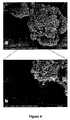
- FIGS. 4A and 4Bare SEM images of carbon black powder including images of primary particles, aggregates, and agglomerations
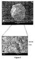
- FIGS. 5A and 5Bare SEM images of a single UHMWPE granule
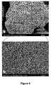
- FIG. 6A and 6Bare SEM images of a single UHMWPE granule following formation of a powder mixture including 8 wt % carbon black with UHMWPE;
- FIGS. 7A-7Care images of increasing magnification of a section of an UHMWPE/CB composite material following compression molding formed according to the present invention.
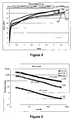
- FIG. 8graphically illustrates the stress v. strain curve for exemplary composite conductive materials of the present invention
- FIG. 9graphically illustrates the log of resistance vs. log of the load for three different composite conductive materials of the present invention.
- FIG. 10illustrates the log of normalized resistance vs. log of the load for three different composite conductive materials of the present invention
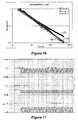
- FIG. 11illustrates the voltage values corresponding to load, position, and resistance of an exemplary composite material
- FIGS. 12A-12Dillustrate the kinematics and contact area for exemplary artificial knee implant sensors of the present invention with different surface geometries.
- FIGS. 13A and 13Bgraphically illustrate the log of normalized resistance vs. log of the compressive force for two different composite conductive materials of the present invention.
- the term primary particleis intended to refer to the smallest particle, generally spheroid, of a material such as carbon black.
- aggregateis intended to refer to the smallest unit of a material, and in particular, of carbon black, found in a dispersion. Aggregates of carbon black are generally considered indivisible and are made up of multiple primary particles held together by strong attractive or physical forces.
- granuleis also intended to refer to the smallest unit of a material found in a dispersion.
- a granulecan also be an aggregate, such as when considering carbon black, this is not a requirement of the term.
- a single granule of a polymersuch as UHMWPE or conventional grade polyethylene, for example can be a single unit.
- agglomerationis intended to refer to a configuration of a material including multiple aggregates or granules loosely held together, as with Van der Waals forces. Agglomerations of material in a dispersion can often be broken down into smaller aggregates or granules upon application of sufficient energy so as to overcome the attractive forces.
- conventional polymeris intended to refer to polymers that have a thermal resistance below about 100° C. and relatively low physical properties. Examples include high-density polyethylene (PE), polystyrene (PS), polyvinyl chloride (PVC), and polypropylene (PP).
- PEhigh-density polyethylene
- PSpolystyrene
- PVCpolyvinyl chloride
- PPpolypropylene
- engineering polymeris intended to refer to polymers that have a thermal resistance between about 100° C. and about 150° C. and exhibit higher physical properties, such as strength and wear resistance, as compared to conventional polymers. Examples include polycarbonates (PC), polyamides (PA), polyethylene terephthalate (PET), and ultrahigh molecular weight polyethylene (UHMWPE).
- PCpolycarbonates
- PApolyamides
- PETpolyethylene terephthalate
- UHMWPEultrahigh molecular weight polyethylene
- high performance polymeris intended to refer to polymers that have a thermal resistance greater than about 150° C. and relatively high physical properties. Examples include polyetherether ketone (PEEK), polyether sulfone (PES), polyimides (PI), and liquid crystal polymers (LC).
- PEEKpolyetherether ketone
- PESpolyether sulfone
- PIpolyimides
- LCliquid crystal polymers
- Contact stresssynonymous with contact pressure, is herein defined as surface stress resulting from the mechanical interaction of two members. It is equivalent to the applied load (total force applied) divided by the area of contact.
- Internal stressrefers to the forces acting on an infinitely small unit area at any point within a material. Internal stress varies throughout a material and is dependent upon the geometry of the member as well as loading conditions and material properties.
- Impact forceis herein defined to refer to the time-dependent force one object exerts onto another object during a dynamic collision.
- the present inventionis generally directed to contact sensors, methods of forming contact sensors, and methods of advantageously utilizing the sensors.
- contact sensorscan be utilized to gather dynamic and/or static contact data at the junction of two opposing members such as a junction found in a joint, a bearing, a coupling, a connection, or any other junction involving the mechanical interaction of two opposing members, and including junctions with either high or low tolerance values as well as junctions including intervening materials between the members, such as lubricated junctions, for instance.
- Dynamic and/or static data that can be gathered utilizing the disclosed sensorscan include, for example, load data, lubrication regimes, wear modes, contact stress data, internal stress data, and/or impact data for a member forming the junction.
- the contact sensors of the present inventioncan provide extremely accurate data for the junction being examined, particularly in those embodiments wherein at least one of the members forming the junction in the working setting (as opposed, for instance, to a testing setting) is formed of a polymeric material.
- the sensors of the present inventioncan include an essentially non-flexible surface that can be shaped to replicate either one of the mating surfaces forming the junction.
- the sensorin a laboratory-type testing application, can simulate one member forming the junction, and contact data can be gathered for the junction under conditions closer to those expected during actual use, i.e., without altering the expected contact dynamics experienced at the junction during actual use.
- the disclosed sensorscan provide contact data for the junction without the necessity of including extraneous testing material, such as dyes, thin films, or the like, within the junction itself.
- the senorcan be formed of a material that essentially duplicates the physical characteristics of the junction member that the sensor is replicating. Accordingly, in this embodiment, the sensor can exhibit wear characteristics essentially equivalent to those of the member when utilized in the field, providing even more accurate testing data. According to one particular embodiment of the invention, rather than being limited to merely simulating a junction-forming member, such as in a pure testing situation, the sensor can be incorporated into the member itself that is destined for use in the working application, i.e., in the field, and can provide contact data for the junction during actual use of the part, for instance in an industrial, medical, or other working setting.
- the contact sensors of the present inventioninclude an electrically conductive composite material that in turn includes at least one non-conductive polymer material combined with an electrically conductive filler.
- the composite material of the present inventioncan include an electrically conductive filler that can provide pressure sensitive electrical conductivity to the composite material, but can do so while maintaining the physical characteristics, e.g., wear resistance, hardness, etc., of the non-conductive polymeric material of the composite.
- the sensors of the present inventioncan be developed to include a particular polymer or combination of polymers so as to essentially replicate the physical characteristics of the similar but non-conductive polymeric member forming the junction to be examined.
- junctionsincluding at least one member formed of engineering and/or high performance polymers.
- the addition of even a relatively small amount of additive or fillercan drastically alter the physical characteristics that provide the desired performance of the materials.
- the high levels of additivesgreater than about 20% by weight, in most instances
- the examination of junctions formed with such materialshas in the past generally required the addition of an intervening material, such as a pressure sensitive film within the junction, leading to the problems discussed above.
- the presently disclosed sensorscan be of great benefit when formed to include engineering and/or high performance polymeric composite materials, this is not a requirement of the invention.
- the polymer utilized to form the composite materialcan be a more conventional polymer. No matter what polymer, copolymer, or combination of polymers is used to form the disclosed composite conductive materials, the composite materials of the disclosed sensors can exhibit pressure sensitive electrical conductivity and if desired, can also be formed so as to essentially maintain the physical characteristics of a polymeric material identical to the composite but for the lack of the conductive filler.
- any polymeric material that can be combined with an electrically conductive filler to form a pressure sensitive conductive polymeric composite material that can then be formed into an essentially inflexible shapecan be utilized in the present invention.
- various polyolefins, polyurethanes, polyester resins, epoxy resins, and the likecan be utilized in the present invention.
- the composite materialcan include engineering and/or high performance polymeric materials.
- the composite materialcan include UHMWPE. UHMWPE is generally classified as an engineering polymer, and possesses a unique combination of physical and mechanical properties that allows it to perform extremely well in rigorous wear conditions.
- UHMWPEhas the highest known impact strength of any thermoplastic presently made, and is highly resistant to abrasion, with a very low coefficient of friction.
- the physical characteristics of UHMWPEhave made it attractive in a number of industrial and medical applications. For instance, it is commonly used in forming polymeric gears, sprockets, impact surfaces bearings, bushings and the like. In the medical industry, UHMWPE is commonly utilized in forming replacement joints including portions of artificial hips, knees, and shoulders.
- UHMWPEcan be in particulate form at ambient conditions and can be shaped through compression molding or RAM extrusion and can optionally be machined to form an essentially inflexible block (i.e., not easily misshapen or distorted), with any desired surface shape.
- Conductive fillers as are generally known in the artcan be combined with the polymeric material of choice to form the composite material of the disclosed sensors.
- a non-limiting list of exemplary conductive fillers suitable for use in the present inventioncan include, for instance, carbon, gold, silver, aluminum, copper, chromium, nickel, platinum, tungsten, titanium, iron, zinc, lead, molybdenum, selenium, indium, bismuth, tin, magnesium, manganese, cobalt, titanium germanium, mercury, and the like.
- a pressure sensitive conductive composite materialcan be formed by combining a relatively small amount of a conductive filler with a polymeric material.
- the compositecan include less than about 10% by weight of the conductive filler.
- the composite materialscan include less than about 8% by weight of the conductive filler.
- the composite materialcan include less than about 5% by weight filler, for instance, less than about 1 wt % in one embodiment.
- the composite materialcan include a higher weight percentage of the conductive filler material.
- the polymeric material and the conductive fillercan be combined in any suitable fashion, which can generally be determined at least in part according to the characteristics of the polymeric material.
- the materialscan be combined by mixing at a temperature above the melting temperature of the polymer (conventional melt-mixing) and the filler materials can be added to the molten polymer, for instance, in a conventional screw extruder, paddle blender, ribbon blender, or any other conventional melt-mixing device.
- the materialscan also be combined by mixing the materials in an appropriate solvent for the polymer (conventional solution-mixing or solvent-mixing) such that the polymer is in the aqueous state and the fillers can be added to the solution, optionally utilizing an appropriate surfactant if desired, following which the solvent can be allowed or encouraged to evaporate, resulting in the solid conductive composite material.
- the materialscan be mixed below the melting point of the polymer and in dry form, for instance, in a standard vortex mixer, a paddle blender, a ribbon blender, or the like, such that the dry materials are mixed together before further processing.
- the mixingcan be carried out at any suitable conditions.
- the components of the composite materialcan be mixed at ambient conditions.
- mixing conditionscan be other than ambient, for instance so as to maintain the materials to be mixed in the desired physical state and/or to improve the mixing process.
- the relative particulate size of the materials to be combined in the mixturecan be important.
- the relative particulate size of the materials to be combinedcan be important in those embodiments wherein a relatively low amount of conductive filler is desired and in those embodiments wherein the polymer granules do not completely fluidize during processing.
- the relative particle sizecan be important in certain embodiments wherein engineering or high-performance polymers are utilized, and in particular, in those embodiments utilizing extremely high melt viscosity polymers such as UHMWPE, which can be converted via non-fluidizing conversion processes, such as compression molding or RAM extrusion processes.
- the particle size of the fillercan beneficially be considerably smaller than the particle size of the polymer. According to this embodiment, and while not wishing to be bound by any particular theory, it is believed that due to the small size of the conductive filler particles relative to the larger polymer particles, the conductive filler is able to completely coat the polymer during mixing and, upon conversion of the composite polymeric powder in a non-fluidizing conversion process to the final solid form, the inter-particle distance of the conductive filler particles can remain above the percolation threshold such that the composite material can exhibit the desired electrical conductivity.
- the granule or aggregate size of the conductive filler to be mixed with the polymercan be at least about two orders of magnitude smaller than the granule size of the polymer. In some embodiments, the granule or aggregate size of the conductive filler can be at least about three orders of magnitude smaller than the granule size of the polymer.
- a granular polymersuch as the UHMWPE illustrated in FIG. 5
- a conductive fillerthat is also in particulate form.
- FIG. 5Ais an FESEM image of a single UHMWPE granule.
- the granule shown in FIG. 5Ahas a diameter of approximately 150 ⁇ m, though readily available UHMWPE in general can have a granule diameter in a range of from about 50 ⁇ m to about 200 ⁇ m.
- FIG. 5Bis an enlarged FESEM image of the boxed area shown on FIG. 5A .
- the individual granuleis made up of multiple sub-micron sized spheroids and nano-sized fibrils surrounded by varying amounts of free space.
- carbon black conductive fillercan be mixed with the polymer.
- Carbon blackis readily available in a wide variety of agglomerate sizes, generally ranging in diameter from about 1 ⁇ m to about 100 ⁇ m, that can be broken down into smaller aggregates of from about 10 nm to about 500 nm upon application of suitable energy.
- FIG. 4Ais an FESEM image of a carbon black powder agglomerate having a diameter of approximately 10 ⁇ m.
- FIG. 4Bindividual carbon black aggregates forming the agglomerate can clearly be distinguished.
- the circled section of FIG. 4Bshows a single carbon black aggregate loosely attached to the larger agglomerate. As the scale of FIG.
- the aggregates in this particular imagerange in size from about 50 nm to about 500 nm.
- the smaller, spherical primary particles of carbon blackthe size of which are often utilized when classifying commercial carbon black preparations. These primary particles make up the aggregate.
- FIG. 6A and 6Bshow FESEM micrographs of a single powder particle obtained following mixing of 8 wt % carbon black with 92 wt % UHMWPE. As can be seen, the UHMWPE particle is completely coated with carbon black aggregates.
- the mixturecan be converted as desired to form a solid composite material that is electrically conductive.
- the solid composite thus formedcan also maintain the physical characteristics of the polymer in those embodiments including a relatively low filler level in the composite.
- the powderin which the composite material includes a conductive filler mixed with UHMWPE, the powder can be converted via a compression molding process or a RAM extrusion process, as is generally known in the art, optionally followed by machining of the solid molded material, for instance in those embodiments wherein a contact sensor describing a complex contact surface curvature is desired.
- the polymeric portion of the composite materialcan be a polymer, a co-polymer, or a mixture of polymers that can be suitable for other converting processes, and the composite polymeric material can be converted via, for instance, a relatively simple extrusion or injection molding process.
- the composite material of the disclosed sensorscan optionally include other materials, in addition to the primary polymeric component and the conductive filler discussed above.
- Other fillers that can optionally be included in the disclosed composite materials of the present inventioncan include, for example, various ceramic fillers, aluminum oxide, zirconia, calcium, silicon, fibrous fillers, including carbon fibers and/or glass fibers, or any other fillers as are generally known in the art.
- the composite materialcan include an organic filler, such as may be added to improve sliding properties of the composite material.
- Such fillersinclude, for instance, tetrafluoroethylene or a fluororesin.
- FIGS. 7A-7Care images of a composite material of the present invention including 8 wt % carbon black and UHMWPE following compression molding of the dry mixture.
- FIG. 7Ais a view obtained by optical microscopy showing a segregated network structure including conductive carbon black-containing channels, with the boxed section magnified in an FESEM image shown in FIG. 7B .
- FIG. 7Bthe junction between the channel region and the non-channel region of the composite material is quite abrupt, showing that the carbon black particles did not flow while the composite material was molded above the melt temperature of the polymer.
- FIG. 7Cwhich is the boxed portion of FIG. 7B at increased magnification, clearly shows individual carbon black primary particles and small aggregates under 200 nm in size (with some under 50 nm in size) well dispersed and embedded in the polymer. As can also be seen in FIG. 7C , the distances between many of the individual carbon black primary particles and small aggregates is quite small, believed to be nearing 10 nm.
- the conductivity, and in particular the resistance, of the composite material of the present inventioncan vary upon application of a compressive force (i.e., load) to the composite material.
- the composite materials of the present inventioncan be formed into the sensor shape and placed in electrical communication with a data acquisition terminal that can include, for instance, oscilloscopes and/or a computer including suitable recognition and analysis software that can receive and analyze a stream of data from the sensor.
- a data acquisition terminalcan include, for instance, oscilloscopes and/or a computer including suitable recognition and analysis software that can receive and analyze a stream of data from the sensor.
- the composite material of the sensorcan be hard wired to a data acquisition terminal, such as by machining the composite material to accept a connector of a predetermined geometry within the material itself.
- a suitable connectorcan be attached to the composite material with a conductive adhesive, such as a silver ink, for instance.
- connection regimesas are generally known in the art may optionally be utilized, however, including fixed or unfixed connections to any suitable communication system between the composite material and the data acquisition terminal.
- any suitable communication system between the composite material and the data acquisition terminalmay optionally be utilized, however, including fixed or unfixed connections to any suitable communication system between the composite material and the data acquisition terminal.
- no particular electrical communication systemis required of the present invention.
- the electrical communication between the composite material and the data acquisition terminalcan be wireless, rather than a hard wired connection.
- the contact sensorcan include only a single sensing point.
- the entire contact surface of the disclosed sensorscan be formed of the conductive composite material.
- the contact sensorscan be utilized to obtain impact data and/or the total load on the surface at any time.
- Such an embodimentcan be preferred, for example, in order to obtain total load or impact data for a member without the necessity of having external load cells or strain gauges in communication with the load-bearing member.
- This sensor typemay be particularly beneficial in those embodiments wherein the sensor is intended to be incorporated with or as the member for use in the field.
- any polymeric load-bearing member utilized in a processcould be formed from the physically equivalent but conductive composite material according to the present invention and incorporated into the working process to provide real time wear and load data of the member with no cost in wear performance to the member due to the acquisition of conductive capability.
- the sensors of the present inventioncan include multiple sensing points and can provide more detailed data about the junction or the members forming the junction.
- multiple sensing pointscan provide data describing the distribution of contact stresses and/or internal stresses, data concerning types of wear modes, or data concerning a lubrication regime as well as load and impact data for a member forming a junction.
- the composite materialcan be located at predetermined, discrete regions of a sensor to form multiple sensing points on or in the sensor and a non-conductive material can separate the discrete sensing points from one another.
- Data from the multiple discrete sensing pointscan then be correlated and analyzed and can provide information concerning, for instance, the distribution of contact characteristics across the entire mating surface, and in particular can provide contact information under dynamic loading conditions involving, for example, sliding, rolling, or grinding motions across the surface of the sensor.
- FIG. 1is a schematic diagram of one embodiment of the sensor of the present invention including multiple sensing points at the essentially inflexible contact surface of the junction member.
- Surface sensing pointssuch as those in this embodiment can be utilized to determine contact surface data, including, for example, contact stress data, lubrication data, impact data, and information concerning wear modes.
- the polymeric sensor 10includes a contact surface 8 for contact with a metallic component (not shown) to simulate the dynamic characteristics of the joint formed between the sensor and the metallic component.
- the contact surface 8describes a curvature to simulate that of the tibial plateau of an artificial knee implant.
- the sensor 10includes multiple sensing points 12 at the contact surface 8 of the sensor 10 .
- the sensing points 12can be formed of the conductive composite material as herein described.
- an electrical signalcan be generated and sent via wire 18 to a data acquisition location.
- every single sensing point 12can be wired so as to provide data from that point to the data acquisition location. Due to the deformable nature of the polymeric composite material, the characteristics of the generated electrical signal can vary with the variation in load applied at the sensing point 12 and a dynamic contact stress distribution profile for the joint can be developed.
- the surface area and geometry of any individual sensing point 12 as well as the overall geometric arrangement of the plurality of sensing points 12 over the surface 8 of the sensor 10can be predetermined as desired. For example, through the formation and distribution of smaller sensing points 12 with less intervening space between individual sensing points 12 , the spatial resolution of the data can be improved. While there may be a theoretical physical limit to the minimum size of a single sensing point determined by the size of a single polymer granule, practically speaking, the minimum size of the individual sensing points will only be limited by modern machining and electrical connection forming techniques. In addition, increased numbers of data points can complicate the correlation and analysis of the data. As such, the preferred geometry and size of the multiple sensing points can generally involve a compromise between the spatial resolution obtained and complication of formation methods.
- the composite material forming the surface sensing points 12can extend to the base 15 of the sensor 10 , where electrical communication can be established to a data acquisition and analysis location (not shown), such as a computer with suitable software, for example.
- the discrete sensing points 12 of the sensor 10 of FIG. 1are separated by a non-conductive material 14 that can, in one embodiment, be formed of the same polymeric material as that contained in the composite material forming the sensing points 12 .
- the method of combining the two materials to form the sensorcan be any suitable formation method.
- the composite materialcan be formed into the desirable shape, such as multiple individual rods of composite material as shown in the embodiment illustrated in FIG. 1 , and then these discrete sections can be inserted into a block of the non-conductive polymer that has had properly sized holes cut out of the block.
- the two polymeric components of the sensorcan then be fused, such as with heat and/or pressure, and any final shaping of the two-component sensor, such as surface shaping via machining, for instance, can be carried out so as to form the sensor 10 including discrete sensing points 12 formed of the conductive composite material at the surface 8 .
- the sensor 10can have uniform physical characteristics across the entire sensor 10 , i.e., both at the sensing points 12 and in the intervening space 14 between the composite material.
- the polymer used to form the sensor 10can be the same polymer as is used to form the member for use in the field.
- the polymer used to form both the composite material at the sensing points 12 and the material in the intervening space 14 between the sensing points 12can be formed of the same polymer as that expected to be used to form the polymeric bearing component of the implantable device (e.g., UHMWPE or polyurethane).
- the sensor 10can provide real time, accurate, dynamic contact data for the implantable polymeric bearing under expected conditions of use.
- the surface 8 of the sensor 10can be coated with a lubricating fluid, and in particular, a lubricating fluid such as may be utilized for the bearing during actual use and under the expected conditions of use (e.g., pressure, temperature, etc.).
- a lubricating fluidsuch as may be utilized for the bearing during actual use and under the expected conditions of use (e.g., pressure, temperature, etc.).
- the disclosed sensorscan also be utilized to examine data concerning contact through an intervening material, i.e., lubrication regimes under expected conditions of use.
- the sensorcan be utilized to determine the type and/or quality of lubrication occurring over the surface of the sensor including variation in fluid film thickness across the surface during use.
- thiscan merely be determined by presence or absence of fluid, e.g., presence or absence of direct contact data (i.e., current flow) in those embodiments wherein the fluid is a non-conductive lubricating fluid.
- a more detailed analysiscan be obtained, such as determination of variation in fluid film thickness.
- This informationcan be obtained, for example, by comparing non-lubricated contact data with the data obtained from the same joint under the same loading conditions but including the intervening lubricant.
- such informationcould be obtained through analysis of the signal obtained upon variation of the frequency and amplitude of the applied voltage.
- the sensorcan be utilized in a capacitance mode, in order to obtain the exact distance between the two surfaces forming the joint.
- the disclosed sensorcan be utilized to determine a lubrication distribution profile of the contact surface over time.
- FIG. 2illustrates another embodiment of the contact sensors of the present invention.
- the sensorincludes multiple sensing strips 16 across the surface 8 of the sensor 10 .
- the orientation of the individual sensing strips 16 across the different condoyles formed on the single sensor surfacecan be varied from one another.
- stripscan be laid in different orientations on separate but identically shaped sensors in a multi-sensor testing apparatus.
- virtual cross-pointscan be created when the data from the different surfaces is correlated.
- a virtual data point at the cross-pointcan be created.
- this embodimentcan necessitate the formation of fewer electrical connections and wires 18 in order to provide data to the acquisition and analysis location, which may be preferred in some embodiments due to increased system simplicity.
- the contact sensors of the present inventioncan be utilized to provide sub-surface stress data.
- multiple sensing strips 16can be located within a subsurface layer at a predetermined depth of the sensor.
- the horizontal and vertical strips 16can cross each other with a conductive material located between the cross points to form a subsurface sensing point 15 at each cross point.
- the strips 16can be formed of the composite material described herein with the intervening material being the same basic composite material but with a lower weight percentage of the conductive filler, and the layer can be laid within the insulating non-conductive polymer material 14 .
- the sensing strips 16can be any conductive material, such as a metallic wire, for example, laid on either side of a sheet or section of the composite material, and the layer can then be located at a depth from the surface 8 of the sensor.
- Application of a load at the surface 8 of the sensorcan then vary the electronic characteristics at the internal sensing point 15 .
- the current flow at any point 15can vary in proportion to the stress at that point.
- an internal stress profile for the sensorcan be developed at that particular depth.
- the sensorscan include multiple layers at different depths from the surface 8 , each layer including one or more internal stress points 15 .
- a stress profile as a function of depth from the surface 8can be developed for the sensor.
- both subsurface contact data and surface contact datacan be gathered from a single sensor through combination of the above-described embodiments.
- Virgin UHMWPE powder and the four UHMWPE/CB powder mixtureswere then compression-molded into rectangular sheets 12 cm long, 8.5 cm wide, and 2 mm thick using a mold consisting of a 2 mm thick Teflon frame sandwiched between 2 stainless steel plates that were coated with Teflon mold release spray.
- the powderswere processed in a laboratory press (Carver Laboratory Press, Model C, Fred S. Carver Inc., Wabash, Ind.) equipped with electric heaters for 20 minutes at a temperature of 205° C. and a pressure of 10 MPa. The specimens were then quenched under pressure at a cooling rate of 50 ° C./min.
- FIG. 7A-7Care images of the composite material including 8 wt % CB following compression molding of the powder.
- FIG. 9shows a plot of the log of the resistance as a function of the log of the compressive load applied to the UHMWPE/CB composites of 0.5% ( 24 ), 1% ( 26 ), and 8% ( 28 ).
- the plotshows that the composites have the same slope, but that the intercepts are different, with the 0.5% composite having the highest intercept, and the 8% composite having the lowest intercept.
- the value of resistancechanged by about two orders of magnitude for each composite.
- the correlation coefficients of each regression lineindicated a good fit.
- the values of resistancewere normalized (shown in FIG. 10 )
- the curves for the three compositeswere very similar, suggesting that the amount of CB only affected the magnitude of the resistance.
- the relative response to applied loadappeared to be independent of the amount of CB.
- the control sample and the 0.25% CB samplehad high resistance for all loads tested and thus were not included on FIGS. 9 and 10 .
- FIG. 11shows the voltage values corresponding to the compressive load, the compressive displacement, and the resistance of the 8 wt % CB composite while the composite was loaded cyclically with a haversine wave at 1 Hz.
- the top curvecorresponds to the compressive stress
- the middle curvecorresponds to the compressive strain
- the bottom curvecorresponds to the resistance of the sensor material.
- This datarepresents the cyclic response of the material, indicating that it does not experience stress-relaxation at a loading frequency of 1 Hz.
- the results of this cyclic testingshow that the peak voltage values corresponding to resistance remain nearly constant over many cycles. Therefore, the data seem to indicate that the sensor material should be well suited for cyclic measurements since the readings do not degrade over time.
- Compression moldingwas used to form 2 rectangular blocks of 1150 UHMWPE doped with 8 wt % carbon black filler as described above for Example 1.
- the blocks formedincluded a 28 ⁇ 18 matrix of surface sensing points 12 as shown in FIG. 1 .
- the pointswere circular with a 1/16 th inch (1.59 mm) diameter and spaced every 1/10 th inch (2.54 mm).
- the blockswere then machined to form both a highly-conforming, PCL-sacrificing tibial insert (Natural Knee II, Ultra-congruent size 3, Centerpulse Orthopedics, Austin, Tex.) and a less conforming PCL-retaining tibial insert (Natural Knee II, Standard-congruent, size 3, Centerpulse Orthopedics, Austin, Tex.) as illustrated in FIG. 1 .
- the implantswere then aligned and potted directly in PMMA in the tibial fixture of a multi-axis, force-controlled knee joint simulator (Stanmore/Instron, Model KC Knee Simulator).
- Static testingwas performed with an axial load of 2.9 kN (4 ⁇ B.W.) at flexion angles of 0°, 30°, 60°, and 80°, to eliminate the effects of lubricant and to compare the sensor reading to the literature.
- the dynamic contact areawas then measured during a standard walking cycle using the proposed 1999 ISO force-control testing standard, #14243. Data was collected and averaged over 8 cycles.
- a pure hydrocarbon, light olive oilwas used as the lubricant due to its inert electrical properties.
- the results from dynamic testing with a standard walking protocol, shown in FIG. 12show the effects that the lubricant had on the dynamic contact area.
- Contact areawas registered by the sensor when physical contact occurred between the femoral component and any sensing point, allowing electrical current to flow. Because the lubricant was electrically insulating, fluid-film lubrication over a sensing point caused no contact to be registered at that point.
- the lower contact area measured for the ultra-congruent insert during the stance phase of gaitwas due to the fluid-film lubrication that occurred with the more conforming insert.
- the rapid changes in contact area measured for the standard-congruent insert during the mid-stance phasesuggests that the mode of lubrication is quite sensitive to the dynamic loading patterns.
- Tecoflex SG-80Aa medical grade soft polyurethane available from Thermedics Inc. (Woburn, Mass.), was solution processed and molded including 4 wt % and 48 wt % CB to form two solid sample materials.
- FIGS. 13A and 13Bgraphically illustrate the resistance vs. compressive force applied to the samples for the 4% and 48% non-surfactant mixed samples, respectively. As can be seen, both samples showed pressure sensitive conductive characteristics suitable for forming the sensors of the present invention where the value of resistance can be controlled with the amount of conductive filler added.
Landscapes
- Health & Medical Sciences (AREA)
- Life Sciences & Earth Sciences (AREA)
- Physics & Mathematics (AREA)
- Medical Informatics (AREA)
- Surgery (AREA)
- Biophysics (AREA)
- Pathology (AREA)
- Engineering & Computer Science (AREA)
- Biomedical Technology (AREA)
- Heart & Thoracic Surgery (AREA)
- Dentistry (AREA)
- Molecular Biology (AREA)
- Oral & Maxillofacial Surgery (AREA)
- Animal Behavior & Ethology (AREA)
- General Health & Medical Sciences (AREA)
- Public Health (AREA)
- Veterinary Medicine (AREA)
- Orthopedic Medicine & Surgery (AREA)
- Rheumatology (AREA)
- General Physics & Mathematics (AREA)
- Compositions Of Macromolecular Compounds (AREA)
- Force Measurement Appropriate To Specific Purposes (AREA)
Abstract
Description
| 0.25 wt % | 0.50 | 1 | 8 wt % | ||
| n = 4 | Control | CB | CB | CB | CB |
| Young's Modulus | 214.8 ± 21.1 | 208.48 ± 7.68 | 211.9 ± 7.74 | 212.6 ± 6.82 | 208.9 ± 11.1 |
| (MPa) | |||||
| Tensile Strength | 30.8 ± 3.98 | 29.1 ± 2.23 | 32.6 ± 3.49 | 31.9 ± 2.43 | 31.7 ± 1.03 |
| (MPa) | |||||
| Yield Strength | 17.8 ± 0.75 | 18.0 ± 0.87 | 17.8 ± 0.93 | 15.2 ± 0.96 | 22.2 ± 1.07 |
| (MPa) | |||||
| Elongation at | 390 ± 77.0 | 360 ± 18.0 | 390 ± 18.0 | 340 ± 23 | 290 ± 41 |
| Break (%) | |||||
Claims (23)
Priority Applications (2)
| Application Number | Priority Date | Filing Date | Title |
|---|---|---|---|
| US11/058,433US7849751B2 (en) | 2005-02-15 | 2005-02-15 | Contact sensors and methods for making same |
| US12/966,257US8234929B2 (en) | 2005-02-15 | 2010-12-13 | Contact sensors and methods for making same |
Applications Claiming Priority (1)
| Application Number | Priority Date | Filing Date | Title |
|---|---|---|---|
| US11/058,433US7849751B2 (en) | 2005-02-15 | 2005-02-15 | Contact sensors and methods for making same |
Related Child Applications (1)
| Application Number | Title | Priority Date | Filing Date |
|---|---|---|---|
| US12/966,257ContinuationUS8234929B2 (en) | 2005-02-15 | 2010-12-13 | Contact sensors and methods for making same |
Publications (2)
| Publication Number | Publication Date |
|---|---|
| US20060184067A1 US20060184067A1 (en) | 2006-08-17 |
| US7849751B2true US7849751B2 (en) | 2010-12-14 |
Family
ID=36816591
Family Applications (2)
| Application Number | Title | Priority Date | Filing Date |
|---|---|---|---|
| US11/058,433Expired - Fee RelatedUS7849751B2 (en) | 2005-02-15 | 2005-02-15 | Contact sensors and methods for making same |
| US12/966,257Expired - Fee RelatedUS8234929B2 (en) | 2005-02-15 | 2010-12-13 | Contact sensors and methods for making same |
Family Applications After (1)
| Application Number | Title | Priority Date | Filing Date |
|---|---|---|---|
| US12/966,257Expired - Fee RelatedUS8234929B2 (en) | 2005-02-15 | 2010-12-13 | Contact sensors and methods for making same |
Country Status (1)
| Country | Link |
|---|---|
| US (2) | US7849751B2 (en) |
Cited By (35)
| Publication number | Priority date | Publication date | Assignee | Title |
|---|---|---|---|---|
| US20090005708A1 (en)* | 2007-06-29 | 2009-01-01 | Johanson Norman A | Orthopaedic Implant Load Sensor And Method Of Interpreting The Same |
| US20100139413A1 (en)* | 2007-07-02 | 2010-06-10 | Wolfram Herrmann | Strain sensor and corresponding sensor arrangement |
| US20100180691A1 (en)* | 2009-01-16 | 2010-07-22 | Kianoosh Hatami | Sensor-enabled geosynthetic material and method of making and using the same |
| US20100249660A1 (en)* | 2009-03-31 | 2010-09-30 | Sherman Jason T | System and method for displaying joint force data |
| US20100249777A1 (en)* | 2009-03-31 | 2010-09-30 | Sherman Jason T | Device and method for determining forces of a patient's joint |
| US20100249659A1 (en)* | 2009-03-31 | 2010-09-30 | Sherman Jason T | Device and method for displaying joint force data |
| US20120123716A1 (en)* | 2009-06-03 | 2012-05-17 | Clark Andrew C | Contact sensors and methods for making same |
| US20120186356A1 (en)* | 2010-07-27 | 2012-07-26 | Norman Stark | Synthetic synovial fluid compositions and methods for making the same |
| US20130079669A1 (en)* | 2011-09-23 | 2013-03-28 | Orthosensor | Small form factor muscular-skeletal parameter measurement system |
| US20130226034A1 (en)* | 2012-02-27 | 2013-08-29 | Orthosensor Inc. | Measurement device for the muscular-skeletal system having load distribution plates |
| US20130281793A1 (en)* | 2011-01-13 | 2013-10-24 | Sensurtec, Inc. | Breach detection in solid structures |
| US20140026682A1 (en)* | 2012-07-27 | 2014-01-30 | Seda Chemical Products Co., Ltd. | Imperceptible motion sensing device having conductive elastomer |
| US8721568B2 (en) | 2009-03-31 | 2014-05-13 | Depuy (Ireland) | Method for performing an orthopaedic surgical procedure |
| US8752438B2 (en)* | 2009-01-16 | 2014-06-17 | The Board Of Regents Of The University Of Oklahoma | Sensor-enabled geosynthetic material and method of making and using the same |
| US8820173B2 (en) | 2009-03-06 | 2014-09-02 | Andrew C. Clark | Contact sensors and methods for making same |
| US20140331412A1 (en)* | 2008-03-15 | 2014-11-13 | Stryker Corporation | Force sensing sheet |
| US9308102B2 (en) | 2013-03-04 | 2016-04-12 | Howmedica Osteonics Corp. | Acetabular cup positioning device |
| US9381011B2 (en) | 2012-03-29 | 2016-07-05 | Depuy (Ireland) | Orthopedic surgical instrument for knee surgery |
| US9538953B2 (en) | 2009-03-31 | 2017-01-10 | Depuy Ireland Unlimited Company | Device and method for determining force of a knee joint |
| US9545459B2 (en) | 2012-03-31 | 2017-01-17 | Depuy Ireland Unlimited Company | Container for surgical instruments and system including same |
| US20170135494A1 (en)* | 2015-11-17 | 2017-05-18 | Dreamwell, Ltd. | Mattress with flexible pressure sensor |
| US10070973B2 (en) | 2012-03-31 | 2018-09-11 | Depuy Ireland Unlimited Company | Orthopaedic sensor module and system for determining joint forces of a patient's knee joint |
| US10206792B2 (en) | 2012-03-31 | 2019-02-19 | Depuy Ireland Unlimited Company | Orthopaedic surgical system for determining joint forces of a patients knee joint |
| US10760983B2 (en) | 2015-09-15 | 2020-09-01 | Sencorables Llc | Floor contact sensor system and methods for using same |
| US11129605B2 (en) | 2016-12-22 | 2021-09-28 | Orthosensor Inc. | Surgical apparatus to support installation of a prosthetic component and method therefore |
| US11185425B2 (en) | 2016-12-22 | 2021-11-30 | Orthosensor Inc. | Surgical tensor configured to distribute loading through at least two pivot points |
| US11266512B2 (en) | 2016-12-22 | 2022-03-08 | Orthosensor Inc. | Surgical apparatus to support installation of a prosthetic component and method therefore |
| US11284873B2 (en) | 2016-12-22 | 2022-03-29 | Orthosensor Inc. | Surgical tensor where each distraction mechanism is supported and aligned by at least two guide shafts |
| US11291437B2 (en) | 2016-12-22 | 2022-04-05 | Orthosensor Inc. | Tilting surgical tensor to support at least one bone cut |
| US11298246B1 (en)* | 2020-05-19 | 2022-04-12 | Little Engine, LLC | Apparatus and method for evaluating knee geometry |
| US11602443B1 (en) | 2022-06-07 | 2023-03-14 | Little Engine, LLC | Knee evaluation and arthroplasty method |
| US11612503B1 (en) | 2022-06-07 | 2023-03-28 | Little Engine, LLC | Joint soft tissue evaluation method |
| US11642118B1 (en) | 2022-06-07 | 2023-05-09 | Little Engine, LLC | Knee tensioner-balancer and method |
| US12201534B2 (en) | 2020-01-29 | 2025-01-21 | Howmedica Osteonics Corp. | Load sensor balancer instruments |
| US12303405B2 (en) | 2023-11-01 | 2025-05-20 | Dynamic Balancer Systems Llc | Knee arthroplasty method |
Families Citing this family (35)
| Publication number | Priority date | Publication date | Assignee | Title |
|---|---|---|---|---|
| CA2598391C (en)* | 2005-02-18 | 2012-05-22 | Ray C. Wasielewski | Smart joint implant sensors |
| WO2006125253A1 (en)* | 2005-05-25 | 2006-11-30 | Royal Melbourne Institute Of Technology | Polymeric strain sensor |
| WO2008019698A1 (en)* | 2006-08-14 | 2008-02-21 | Cherif Atia Algreatly | Motion tracking apparatus and method |
| US7845236B2 (en)* | 2008-08-26 | 2010-12-07 | General Electric Company | Resistive contact sensors for large blade and airfoil pressure and flow separation measurements |
| US8152440B2 (en) | 2008-08-26 | 2012-04-10 | General Electric Company | Resistive contact sensors for large blade and airfoil pressure and flow separation measurements |
| DE102009018179B4 (en)* | 2009-04-22 | 2014-07-10 | Otto Bock Healthcare Gmbh | Structural element for an orthopedic device and orthopedic device |
| US9259179B2 (en) | 2012-02-27 | 2016-02-16 | Orthosensor Inc. | Prosthetic knee joint measurement system including energy harvesting and method therefor |
| US9161717B2 (en) | 2011-09-23 | 2015-10-20 | Orthosensor Inc. | Orthopedic insert measuring system having a sealed cavity |
| US9332943B2 (en)* | 2011-09-23 | 2016-05-10 | Orthosensor Inc | Flexible surface parameter measurement system for the muscular-skeletal system |
| WO2011127306A1 (en)* | 2010-04-07 | 2011-10-13 | Sensortech Corporation | Contact sensors, force/pressure sensors, and methods for making same |
| FR2963228B1 (en)* | 2010-07-28 | 2012-08-03 | Amplitude | DEVICE FOR MEASURING AN EFFORT EXERCISED BY A FEMUR ON A TIBIA FOR THE POSITION OF JOINT PROSTHESIS |
| DE102010041650A1 (en)* | 2010-09-29 | 2012-03-29 | Siemens Aktiengesellschaft | Volume for the collection of vital data of a person |
| US9622701B2 (en) | 2012-02-27 | 2017-04-18 | Orthosensor Inc | Muscular-skeletal joint stability detection and method therefor |
| US20130226036A1 (en)* | 2012-02-27 | 2013-08-29 | Orthosensor Inc. | Measurement device for the muscular-skeletal system having an integrated sensor |
| US9271675B2 (en) | 2012-02-27 | 2016-03-01 | Orthosensor Inc. | Muscular-skeletal joint stability detection and method therefor |
| US9462967B2 (en)* | 2012-07-06 | 2016-10-11 | Zimmer, Inc. | Condyle axis locator |
| JP2016516489A (en) | 2013-03-15 | 2016-06-09 | ウィリアム エル ハンター | Apparatus, system and method for monitoring hip replacements |
| US20140260687A1 (en)* | 2013-03-15 | 2014-09-18 | Beldon Technologies, Inc. | Roof monitoring method and system |
| CN103211666B (en)* | 2013-04-25 | 2016-05-18 | 南京理工大学 | A kind of joint prosthesis load-bearing surface micropore texture that improves lubricated and anti-wear performance |
| CN113274173A (en) | 2013-06-23 | 2021-08-20 | 卡纳里医疗公司 | Devices, systems, and methods for monitoring knee replacements |
| EP4449979A3 (en) | 2014-06-25 | 2025-05-21 | Canary Medical Switzerland AG | Devices, systems and methods for using and monitoring implants |
| EP3160331A4 (en) | 2014-06-25 | 2018-09-12 | Canary Medical Inc. | Devices, systems and methods for using and monitoring orthopedic hardware |
| CA3223705A1 (en) | 2014-06-25 | 2015-12-30 | Canary Medical Switzerland Ag | Devices, systems and methods for using and monitoring spinal implants |
| CA2998709A1 (en) | 2014-09-17 | 2016-03-24 | Canary Medical Inc. | Devices, systems and methods for using and monitoring medical devices |
| KR102854603B1 (en) | 2016-03-23 | 2025-09-04 | 카나리 메디칼 아이엔씨. | Implantable reporting processor for an alert implant |
| US11191479B2 (en) | 2016-03-23 | 2021-12-07 | Canary Medical Inc. | Implantable reporting processor for an alert implant |
| US10524934B2 (en)* | 2016-12-30 | 2020-01-07 | Zimmer, Inc. | Shoulder arthroplasty trial device |
| LU100021B1 (en)* | 2017-01-13 | 2018-07-30 | Adapttech Ltd | Socket fitting system |
| US10893955B2 (en) | 2017-09-14 | 2021-01-19 | Orthosensor Inc. | Non-symmetrical insert sensing system and method therefor |
| CN109708782B (en)* | 2018-12-14 | 2021-02-12 | 中国科学院深圳先进技术研究院 | Knee joint prosthesis gasket three-dimensional force sensor and contact stress measuring method thereof |
| US12232985B2 (en) | 2019-06-06 | 2025-02-25 | Canary Medical Inc. | Intelligent joint prosthesis |
| US20210366610A1 (en) | 2019-06-06 | 2021-11-25 | Canary Medical Inc. | Intelligent joint prosthesis |
| US11812978B2 (en) | 2019-10-15 | 2023-11-14 | Orthosensor Inc. | Knee balancing system using patient specific instruments |
| CN111780898A (en)* | 2020-07-02 | 2020-10-16 | 苏州大学 | A flexible pressure sensor suitable for surface stress measurement and preparation method thereof |
| CN114848245B (en)* | 2022-07-06 | 2022-09-06 | 北京大学 | Knee joint replacement gap balance measurement system, preparation method and measurement method |
Citations (58)
| Publication number | Priority date | Publication date | Assignee | Title |
|---|---|---|---|---|
| US4145317A (en) | 1976-11-29 | 1979-03-20 | Shin-Etsu Polymer Co., Ltd. | Pressure-sensitive resistance elements |
| US4273682A (en) | 1976-12-24 | 1981-06-16 | The Yokohama Rubber Co., Ltd. | Pressure-sensitive electrically conductive elastomeric composition |
| US4302361A (en) | 1978-02-24 | 1981-11-24 | Japan Synthetic Rubber Co., Ltd. | Pressure sensitive conductor |
| US4314227A (en) | 1979-09-24 | 1982-02-02 | Eventoff Franklin Neal | Electronic pressure sensitive transducer apparatus |
| US4394773A (en)* | 1980-07-21 | 1983-07-19 | Siemens Corporation | Fingerprint sensor |
| US4489302A (en) | 1979-09-24 | 1984-12-18 | Eventoff Franklin Neal | Electronic pressure sensitive force transducer |
| US4492949A (en)* | 1983-03-18 | 1985-01-08 | Barry Wright Corporation | Tactile sensors for robotic gripper and the like |
| US4495236A (en) | 1982-11-29 | 1985-01-22 | The Yokohama Rubber Co. Ltd. | Pressure-sensitive electrically conductive composite sheet |
| US4553837A (en)* | 1983-10-24 | 1985-11-19 | Fingermatrix, Inc. | Roll fingerprint processing apparatus |
| US4634623A (en) | 1983-07-18 | 1987-01-06 | The Gates Corporation | Conductive elastomeric ink composition |
| US4734034A (en)* | 1985-03-29 | 1988-03-29 | Sentek, Incorporated | Contact sensor for measuring dental occlusion |
| US4856993A (en) | 1985-03-29 | 1989-08-15 | Tekscan, Inc. | Pressure and contact sensor system for measuring dental occlusion |
| US5033291A (en) | 1989-12-11 | 1991-07-23 | Tekscan, Inc. | Flexible tactile sensor for measuring foot pressure distributions and for gaskets |
| US5042504A (en) | 1987-04-29 | 1991-08-27 | Helmut Huberti | Device for monitoring loads exerted on parts of the body |
| US5083573A (en) | 1990-02-12 | 1992-01-28 | Arms Steven W | Method of and means for implanting a pressure and force sensing apparatus |
| US5197488A (en) | 1991-04-05 | 1993-03-30 | N. K. Biotechnical Engineering Co. | Knee joint load measuring instrument and joint prosthesis |
| US5302936A (en) | 1992-09-02 | 1994-04-12 | Interlink Electronics, Inc. | Conductive particulate force transducer |
| US5422061A (en) | 1988-09-28 | 1995-06-06 | Dai Nippon Insatsu Kabushiki Kaisha | Method of injection molding ultra-high molecular weight polyethylene sliding members |
| US5470354A (en) | 1991-11-12 | 1995-11-28 | Biomet Inc. | Force sensing apparatus and method for orthopaedic joint reconstruction |
| US5541570A (en) | 1994-12-09 | 1996-07-30 | Force Imaging Technologies, Inc. | Force sensing ink, method of making same and improved force sensor |
| US5756904A (en) | 1996-08-30 | 1998-05-26 | Tekscan, Inc. | Pressure responsive sensor having controlled scanning speed |
| US5818956A (en)* | 1995-10-23 | 1998-10-06 | Tuli; Raja Singh | Extended fingerprint reading apparatus |
| US5880976A (en) | 1997-02-21 | 1999-03-09 | Carnegie Mellon University | Apparatus and method for facilitating the implantation of artificial components in joints |
| US5989700A (en) | 1996-01-05 | 1999-11-23 | Tekscan Incorporated | Pressure sensitive ink means, and methods of use |
| US5993400A (en) | 1991-05-23 | 1999-11-30 | Rincoe; Richard G. | Apparatus and method for monitoring contact pressure between body parts and contact surfaces |
| US6032542A (en) | 1997-07-07 | 2000-03-07 | Tekscan, Inc. | Prepressured force/pressure sensor and method for the fabrication thereof |
| US6136412A (en) | 1997-10-10 | 2000-10-24 | 3M Innovative Properties Company | Microtextured catalyst transfer substrate |
| US6207775B1 (en) | 1997-08-29 | 2001-03-27 | The Dow Chemical Company | Homogeneous filled polymer composite |
| US6216545B1 (en) | 1995-11-14 | 2001-04-17 | Geoffrey L. Taylor | Piezoresistive foot pressure measurement |
| US6267011B1 (en) | 1999-03-31 | 2001-07-31 | Exponent, Inc. | Method and apparatus for determining the true stress and true strain behavior of a ductile polymer |
| US6273863B1 (en) | 1999-10-26 | 2001-08-14 | Andante Medical Devices, Ltd. | Adaptive weight bearing monitoring system for rehabilitation of injuries to the lower extremities |
| US6283829B1 (en) | 1998-11-06 | 2001-09-04 | Beaver Creek Concepts, Inc | In situ friction detector method for finishing semiconductor wafers |
| US6319293B1 (en) | 1997-10-10 | 2001-11-20 | 3M Innovative Properties Company | Membrane electrode assembly |
| US6441084B1 (en) | 2000-04-11 | 2002-08-27 | Equistar Chemicals, Lp | Semi-conductive compositions for wire and cable |
| US6447448B1 (en) | 1998-12-31 | 2002-09-10 | Ball Semiconductor, Inc. | Miniature implanted orthopedic sensors |
| US6524742B1 (en) | 1999-02-19 | 2003-02-25 | Amtek Research International Llc | Electrically conductive, freestanding microporous polymer sheet |
| US6543299B2 (en) | 2001-06-26 | 2003-04-08 | Geoffrey L. Taylor | Pressure measurement sensor with piezoresistive thread lattice |
| US20030069644A1 (en)* | 2001-10-05 | 2003-04-10 | Nebojsa Kovacevic | Dual-tray teletibial implant |
| US6583630B2 (en) | 1999-11-18 | 2003-06-24 | Intellijoint Systems Ltd. | Systems and methods for monitoring wear and/or displacement of artificial joint members, vertebrae, segments of fractured bones and dental implants |
| US20040019382A1 (en) | 2002-03-19 | 2004-01-29 | Farid Amirouche | System and method for prosthetic fitting and balancing in joints |
| US20040019384A1 (en)* | 2002-07-24 | 2004-01-29 | Bryan Kirking | Implantable prosthesis for measuring six force components |
| US6693441B2 (en)* | 2001-11-30 | 2004-02-17 | Stmicroelectronics, Inc. | Capacitive fingerprint sensor with protective coating containing a conductive suspension |
| US20040064191A1 (en)* | 2002-09-30 | 2004-04-01 | Wasielewski Ray C. | Apparatus, system and method for intraoperative performance analysis during joint arthroplasty |
| US6769313B2 (en) | 2001-09-14 | 2004-08-03 | Paricon Technologies Corporation | Flexible tactile sensor |
| US20050010302A1 (en)* | 2003-07-11 | 2005-01-13 | Terry Dietz | Telemetric tibial tray |
| US6877385B2 (en) | 2000-11-16 | 2005-04-12 | National Science Council | Contact type micro piezoresistive shear-stress sensor |
| US20050177170A1 (en) | 2004-02-06 | 2005-08-11 | Synvasive Technology, Inc. | Dynamic knee balancer with pressure sensing |
| US20050273170A1 (en)* | 2004-06-08 | 2005-12-08 | Navarro Richard R | Prosthetic intervertebral spinal disc with integral microprocessor |
| US20060047283A1 (en)* | 2004-08-25 | 2006-03-02 | Evans Boyd M Iii | In-vivo orthopedic implant diagnostic device for sensing load, wear, and infection |
| US7080562B2 (en)* | 2003-10-17 | 2006-07-25 | Qortek, Inc. | High-sensitivity pressure conduction sensor for localized pressures and stresses |
| US7162322B2 (en) | 2003-11-28 | 2007-01-09 | The Ohio Willow Wood Company | Custom prosthetic liner manufacturing system and method |
| US7182736B2 (en) | 2000-08-25 | 2007-02-27 | Cleveland Clinic Foundation | Apparatus and method for assessing loads on adjacent bones |
| US7258026B2 (en) | 2003-12-30 | 2007-08-21 | Tekscan Incorporated | Sensor with a plurality of sensor elements arranged with respect to a substrate |
| US20070234819A1 (en)* | 2006-03-29 | 2007-10-11 | Farid Amirouche | Force monitoring system |
| US7311009B2 (en) | 2004-11-17 | 2007-12-25 | Lawrence Livermore National Security, Llc | Microelectromechanical systems contact stress sensor |
| US20080065225A1 (en)* | 2005-02-18 | 2008-03-13 | Wasielewski Ray C | Smart joint implant sensors |
| US7377944B2 (en) | 2002-07-08 | 2008-05-27 | Ossur Hf | Socket liner incorporating sensors to monitor amputee progress |
| US7406386B2 (en) | 2003-07-09 | 2008-07-29 | Aston University | System and method for sensing and interpreting dynamic forces |
Family Cites Families (9)
| Publication number | Priority date | Publication date | Assignee | Title |
|---|---|---|---|---|
| US5060527A (en)* | 1990-02-14 | 1991-10-29 | Burgess Lester E | Tactile sensing transducer |
| US6684717B2 (en)* | 1997-08-05 | 2004-02-03 | Micron Technology, Inc. | High resolution pressure-sensing device having an insulating flexible matrix loaded with filler particles |
| US6073497A (en)* | 1997-08-05 | 2000-06-13 | Micron Technology, Inc. | High resolution pressure sensing device having an insulating flexible matrix loaded with filler particles |
| EP1109499B1 (en)* | 1998-09-04 | 2007-08-15 | Boston Scientific Limited | Detachable aneurysm neck closure patch |
| US7316167B2 (en)* | 2000-05-16 | 2008-01-08 | Fidelica, Microsystems, Inc. | Method and apparatus for protection of contour sensing devices |
| US7337944B2 (en)* | 2001-02-20 | 2008-03-04 | United States Postal Service | Universal delivery and collection box unit (UDCBU) |
| US7430925B2 (en)* | 2005-05-18 | 2008-10-07 | Pressure Profile Systems, Inc. | Hybrid tactile sensor |
| DE102005055842A1 (en)* | 2005-11-23 | 2007-05-24 | Alpha-Fit Gmbh | Pressure sensor for incorporation in clinical test socks or stockings incorporates pressure-sensitive threads or ribbons |
| CA2676207A1 (en)* | 2007-01-24 | 2008-07-31 | Smm Medical Ab | An elastomeric particle having an electrically conducting surface, a pressure sensor comprising said particles, a method for producing said sensor and a sensor system comprising said sensors |
- 2005
- 2005-02-15USUS11/058,433patent/US7849751B2/ennot_activeExpired - Fee Related
- 2010
- 2010-12-13USUS12/966,257patent/US8234929B2/ennot_activeExpired - Fee Related
Patent Citations (62)
| Publication number | Priority date | Publication date | Assignee | Title |
|---|---|---|---|---|
| US4145317A (en) | 1976-11-29 | 1979-03-20 | Shin-Etsu Polymer Co., Ltd. | Pressure-sensitive resistance elements |
| US4273682A (en) | 1976-12-24 | 1981-06-16 | The Yokohama Rubber Co., Ltd. | Pressure-sensitive electrically conductive elastomeric composition |
| US4302361A (en) | 1978-02-24 | 1981-11-24 | Japan Synthetic Rubber Co., Ltd. | Pressure sensitive conductor |
| US4314227B1 (en) | 1979-09-24 | 1989-01-24 | ||
| US4314227A (en) | 1979-09-24 | 1982-02-02 | Eventoff Franklin Neal | Electronic pressure sensitive transducer apparatus |
| US4489302A (en) | 1979-09-24 | 1984-12-18 | Eventoff Franklin Neal | Electronic pressure sensitive force transducer |
| US4394773A (en)* | 1980-07-21 | 1983-07-19 | Siemens Corporation | Fingerprint sensor |
| US4495236A (en) | 1982-11-29 | 1985-01-22 | The Yokohama Rubber Co. Ltd. | Pressure-sensitive electrically conductive composite sheet |
| US4492949A (en)* | 1983-03-18 | 1985-01-08 | Barry Wright Corporation | Tactile sensors for robotic gripper and the like |
| US4634623A (en) | 1983-07-18 | 1987-01-06 | The Gates Corporation | Conductive elastomeric ink composition |
| US4553837A (en)* | 1983-10-24 | 1985-11-19 | Fingermatrix, Inc. | Roll fingerprint processing apparatus |
| US4734034A (en)* | 1985-03-29 | 1988-03-29 | Sentek, Incorporated | Contact sensor for measuring dental occlusion |
| US4856993A (en) | 1985-03-29 | 1989-08-15 | Tekscan, Inc. | Pressure and contact sensor system for measuring dental occlusion |
| US5042504A (en) | 1987-04-29 | 1991-08-27 | Helmut Huberti | Device for monitoring loads exerted on parts of the body |
| US5422061A (en) | 1988-09-28 | 1995-06-06 | Dai Nippon Insatsu Kabushiki Kaisha | Method of injection molding ultra-high molecular weight polyethylene sliding members |
| US5033291A (en) | 1989-12-11 | 1991-07-23 | Tekscan, Inc. | Flexible tactile sensor for measuring foot pressure distributions and for gaskets |
| US5083573A (en) | 1990-02-12 | 1992-01-28 | Arms Steven W | Method of and means for implanting a pressure and force sensing apparatus |
| US5197488A (en) | 1991-04-05 | 1993-03-30 | N. K. Biotechnical Engineering Co. | Knee joint load measuring instrument and joint prosthesis |
| US5360016A (en) | 1991-04-05 | 1994-11-01 | N. K. Biotechnical Engineering Company | Force transducer for a joint prosthesis |
| US5993400A (en) | 1991-05-23 | 1999-11-30 | Rincoe; Richard G. | Apparatus and method for monitoring contact pressure between body parts and contact surfaces |
| US5470354A (en) | 1991-11-12 | 1995-11-28 | Biomet Inc. | Force sensing apparatus and method for orthopaedic joint reconstruction |
| US5302936A (en) | 1992-09-02 | 1994-04-12 | Interlink Electronics, Inc. | Conductive particulate force transducer |
| US5541570A (en) | 1994-12-09 | 1996-07-30 | Force Imaging Technologies, Inc. | Force sensing ink, method of making same and improved force sensor |
| US5818956A (en)* | 1995-10-23 | 1998-10-06 | Tuli; Raja Singh | Extended fingerprint reading apparatus |
| US6216545B1 (en) | 1995-11-14 | 2001-04-17 | Geoffrey L. Taylor | Piezoresistive foot pressure measurement |
| US5989700A (en) | 1996-01-05 | 1999-11-23 | Tekscan Incorporated | Pressure sensitive ink means, and methods of use |
| US5756904A (en) | 1996-08-30 | 1998-05-26 | Tekscan, Inc. | Pressure responsive sensor having controlled scanning speed |
| US5880976A (en) | 1997-02-21 | 1999-03-09 | Carnegie Mellon University | Apparatus and method for facilitating the implantation of artificial components in joints |
| US6032542A (en) | 1997-07-07 | 2000-03-07 | Tekscan, Inc. | Prepressured force/pressure sensor and method for the fabrication thereof |
| US6207775B1 (en) | 1997-08-29 | 2001-03-27 | The Dow Chemical Company | Homogeneous filled polymer composite |
| US6319293B1 (en) | 1997-10-10 | 2001-11-20 | 3M Innovative Properties Company | Membrane electrode assembly |
| US6136412A (en) | 1997-10-10 | 2000-10-24 | 3M Innovative Properties Company | Microtextured catalyst transfer substrate |
| US6283829B1 (en) | 1998-11-06 | 2001-09-04 | Beaver Creek Concepts, Inc | In situ friction detector method for finishing semiconductor wafers |
| US6447448B1 (en) | 1998-12-31 | 2002-09-10 | Ball Semiconductor, Inc. | Miniature implanted orthopedic sensors |
| US6524742B1 (en) | 1999-02-19 | 2003-02-25 | Amtek Research International Llc | Electrically conductive, freestanding microporous polymer sheet |
| US6267011B1 (en) | 1999-03-31 | 2001-07-31 | Exponent, Inc. | Method and apparatus for determining the true stress and true strain behavior of a ductile polymer |
| US6273863B1 (en) | 1999-10-26 | 2001-08-14 | Andante Medical Devices, Ltd. | Adaptive weight bearing monitoring system for rehabilitation of injuries to the lower extremities |
| US6583630B2 (en) | 1999-11-18 | 2003-06-24 | Intellijoint Systems Ltd. | Systems and methods for monitoring wear and/or displacement of artificial joint members, vertebrae, segments of fractured bones and dental implants |
| US6441084B1 (en) | 2000-04-11 | 2002-08-27 | Equistar Chemicals, Lp | Semi-conductive compositions for wire and cable |
| US7182736B2 (en) | 2000-08-25 | 2007-02-27 | Cleveland Clinic Foundation | Apparatus and method for assessing loads on adjacent bones |
| US6877385B2 (en) | 2000-11-16 | 2005-04-12 | National Science Council | Contact type micro piezoresistive shear-stress sensor |
| US6543299B2 (en) | 2001-06-26 | 2003-04-08 | Geoffrey L. Taylor | Pressure measurement sensor with piezoresistive thread lattice |
| US6769313B2 (en) | 2001-09-14 | 2004-08-03 | Paricon Technologies Corporation | Flexible tactile sensor |
| US20030069644A1 (en)* | 2001-10-05 | 2003-04-10 | Nebojsa Kovacevic | Dual-tray teletibial implant |
| US6693441B2 (en)* | 2001-11-30 | 2004-02-17 | Stmicroelectronics, Inc. | Capacitive fingerprint sensor with protective coating containing a conductive suspension |
| US20040019382A1 (en) | 2002-03-19 | 2004-01-29 | Farid Amirouche | System and method for prosthetic fitting and balancing in joints |
| US7377944B2 (en) | 2002-07-08 | 2008-05-27 | Ossur Hf | Socket liner incorporating sensors to monitor amputee progress |
| US20040019384A1 (en)* | 2002-07-24 | 2004-01-29 | Bryan Kirking | Implantable prosthesis for measuring six force components |
| US20040064191A1 (en)* | 2002-09-30 | 2004-04-01 | Wasielewski Ray C. | Apparatus, system and method for intraoperative performance analysis during joint arthroplasty |
| US7406386B2 (en) | 2003-07-09 | 2008-07-29 | Aston University | System and method for sensing and interpreting dynamic forces |
| US20050010302A1 (en)* | 2003-07-11 | 2005-01-13 | Terry Dietz | Telemetric tibial tray |
| US7470288B2 (en)* | 2003-07-11 | 2008-12-30 | Depuy Products, Inc. | Telemetric tibial tray |
| US7080562B2 (en)* | 2003-10-17 | 2006-07-25 | Qortek, Inc. | High-sensitivity pressure conduction sensor for localized pressures and stresses |
| US7162322B2 (en) | 2003-11-28 | 2007-01-09 | The Ohio Willow Wood Company | Custom prosthetic liner manufacturing system and method |
| US7258026B2 (en) | 2003-12-30 | 2007-08-21 | Tekscan Incorporated | Sensor with a plurality of sensor elements arranged with respect to a substrate |
| US20050177170A1 (en) | 2004-02-06 | 2005-08-11 | Synvasive Technology, Inc. | Dynamic knee balancer with pressure sensing |
| US20050273170A1 (en)* | 2004-06-08 | 2005-12-08 | Navarro Richard R | Prosthetic intervertebral spinal disc with integral microprocessor |
| US7097662B2 (en)* | 2004-08-25 | 2006-08-29 | Ut-Battelle, Llc | In-vivo orthopedic implant diagnostic device for sensing load, wear, and infection |
| US20060047283A1 (en)* | 2004-08-25 | 2006-03-02 | Evans Boyd M Iii | In-vivo orthopedic implant diagnostic device for sensing load, wear, and infection |
| US7311009B2 (en) | 2004-11-17 | 2007-12-25 | Lawrence Livermore National Security, Llc | Microelectromechanical systems contact stress sensor |
| US20080065225A1 (en)* | 2005-02-18 | 2008-03-13 | Wasielewski Ray C | Smart joint implant sensors |
| US20070234819A1 (en)* | 2006-03-29 | 2007-10-11 | Farid Amirouche | Force monitoring system |
Non-Patent Citations (11)
| Title |
|---|
| 958-203, DuPont Material Safety Data Sheet. Original 2003. Available Apr. 24, 2006 online. .* |
| 958-203, DuPont Material Safety Data Sheet. Original 2003. Available Apr. 24, 2006 online. <http://www.customcoatingsinternational.com/958-203—051128—2—MSDS.pdf>.* |
| Abstract-Measurement of Dynamic Contact Area and Lubrication Modes in a Highly Conforming and Standard Conforming Tibial Insert Using Polymeric Doping Technology, A. C. Clark, J. D. DesJardins, T. B Pace, and M. LaBerge, Transactions of the 51st Annual Meeting of the Orthopaedic Research Society, vol. 30, 0568, Jan. 2005, 1 page. |
| Abstract—Measurement of Dynamic Contact Area and Lubrication Modes in a Highly Conforming and Standard Conforming Tibial Insert Using Polymeric Doping Technology, A. C. Clark, J. D. DesJardins, T. B Pace, and M. LaBerge, Transactions of the 51st Annual Meeting of the Orthopaedic Research Society, vol. 30, 0568, Jan. 2005, 1 page. |
| Andrew Clark, "Summer Internship in the Department of Bioengineering at Clemson University", Poster displayed Apr. 2001. |
| Article-Analysis of the effect of pressure on compression moulding of UHMWPE, N. C. Parasnis and K. Ramani, Journal of Materials Science: Materials in Medicine, vol. 9, 1998, pp. 165-172. |
| Article—Analysis of the effect of pressure on compression moulding of UHMWPE, N. C. Parasnis and K. Ramani, Journal of Materials Science: Materials in Medicine, vol. 9, 1998, pp. 165-172. |
| Article-Ultra-High Molecular Weight Polyethylene, Stephen Li and Albert H. Burstein, The Journal of Bone and Joint Surgery, vol. 76-A, No. 7, Jul. 1994, pp. 1080-1090. |
| Article—Ultra-High Molecular Weight Polyethylene, Stephen Li and Albert H. Burstein, The Journal of Bone and Joint Surgery, vol. 76-A, No. 7, Jul. 1994, pp. 1080-1090. |
| Clark, Andrew. Summer Internship. Available online Sep. 21, 2003. Accessed Jan. 26, 2010 .* |
| Clark, Andrew. Summer Internship. Available online Sep. 21, 2003. Accessed Jan. 26, 2010 <http://web.archive.org/web/20030921125459/http://www.clemson.edu/agbioeng/bio/andrew.htm>.* |
Cited By (61)
| Publication number | Priority date | Publication date | Assignee | Title |
|---|---|---|---|---|
| US20090005708A1 (en)* | 2007-06-29 | 2009-01-01 | Johanson Norman A | Orthopaedic Implant Load Sensor And Method Of Interpreting The Same |
| US8511174B2 (en)* | 2007-07-02 | 2013-08-20 | Contitech Ag | Strain sensor and corresponding sensor arrangement |
| US20100139413A1 (en)* | 2007-07-02 | 2010-06-10 | Wolfram Herrmann | Strain sensor and corresponding sensor arrangement |
| US20140331412A1 (en)* | 2008-03-15 | 2014-11-13 | Stryker Corporation | Force sensing sheet |
| US9642470B2 (en)* | 2008-03-15 | 2017-05-09 | Stryker Corporation | Force sensing sheet |
| US8752438B2 (en)* | 2009-01-16 | 2014-06-17 | The Board Of Regents Of The University Of Oklahoma | Sensor-enabled geosynthetic material and method of making and using the same |
| US7975556B2 (en)* | 2009-01-16 | 2011-07-12 | The Board Of Regents Of The University Of Oklahoma | Sensor-enabled geosynthetic material and method of making and using the same |
| US20100180691A1 (en)* | 2009-01-16 | 2010-07-22 | Kianoosh Hatami | Sensor-enabled geosynthetic material and method of making and using the same |
| US8820173B2 (en) | 2009-03-06 | 2014-09-02 | Andrew C. Clark | Contact sensors and methods for making same |
| US9649119B2 (en) | 2009-03-31 | 2017-05-16 | Depuy Ireland Unlimited Company | Method for performing an orthopaedic surgical procedure |
| US20100249660A1 (en)* | 2009-03-31 | 2010-09-30 | Sherman Jason T | System and method for displaying joint force data |
| US9538953B2 (en) | 2009-03-31 | 2017-01-10 | Depuy Ireland Unlimited Company | Device and method for determining force of a knee joint |
| US8556830B2 (en)* | 2009-03-31 | 2013-10-15 | Depuy | Device and method for displaying joint force data |
| US8597210B2 (en) | 2009-03-31 | 2013-12-03 | Depuy (Ireland) | System and method for displaying joint force data |
| US20100249777A1 (en)* | 2009-03-31 | 2010-09-30 | Sherman Jason T | Device and method for determining forces of a patient's joint |
| US8721568B2 (en) | 2009-03-31 | 2014-05-13 | Depuy (Ireland) | Method for performing an orthopaedic surgical procedure |
| US8740817B2 (en) | 2009-03-31 | 2014-06-03 | Depuy (Ireland) | Device and method for determining forces of a patient's joint |
| US20100249659A1 (en)* | 2009-03-31 | 2010-09-30 | Sherman Jason T | Device and method for displaying joint force data |
| US9095275B2 (en)* | 2009-06-03 | 2015-08-04 | Andrew C. Clark | Contact sensors and methods for making same |
| US20120123716A1 (en)* | 2009-06-03 | 2012-05-17 | Clark Andrew C | Contact sensors and methods for making same |
| US8716204B2 (en)* | 2010-07-27 | 2014-05-06 | Zimmer, Inc. | Synthetic synovial fluid compositions and methods for making the same |
| US20120186356A1 (en)* | 2010-07-27 | 2012-07-26 | Norman Stark | Synthetic synovial fluid compositions and methods for making the same |
| US8963708B2 (en)* | 2011-01-13 | 2015-02-24 | Sensurtec, Inc. | Breach detection in solid structures |
| US20130281793A1 (en)* | 2011-01-13 | 2013-10-24 | Sensurtec, Inc. | Breach detection in solid structures |
| US9504576B2 (en) | 2011-01-13 | 2016-11-29 | Sensurtec, Inc. | Breach detection in solid structures |
| US20130079669A1 (en)* | 2011-09-23 | 2013-03-28 | Orthosensor | Small form factor muscular-skeletal parameter measurement system |
| US9462964B2 (en)* | 2011-09-23 | 2016-10-11 | Orthosensor Inc | Small form factor muscular-skeletal parameter measurement system |
| US20130226034A1 (en)* | 2012-02-27 | 2013-08-29 | Orthosensor Inc. | Measurement device for the muscular-skeletal system having load distribution plates |
| US9844335B2 (en)* | 2012-02-27 | 2017-12-19 | Orthosensor Inc | Measurement device for the muscular-skeletal system having load distribution plates |
| US9381011B2 (en) | 2012-03-29 | 2016-07-05 | Depuy (Ireland) | Orthopedic surgical instrument for knee surgery |
| US11589857B2 (en) | 2012-03-29 | 2023-02-28 | Depuy Ireland Unlimited Company | Orthopedic surgical instrument for knee surgery |
| US12161314B2 (en) | 2012-03-29 | 2024-12-10 | Depuy Ireland Unlimited Company | Orthopedic surgical instrument for knee surgery |
| US10485530B2 (en) | 2012-03-29 | 2019-11-26 | Depuy Ireland Unlimited Company | Orthopedic surgical instrument for knee surgery |
| US12324752B2 (en) | 2012-03-31 | 2025-06-10 | Depuy Ireland Unlimited Company | Orthopaedic surgical system for determining joint forces of a patient's knee joint |
| US10070973B2 (en) | 2012-03-31 | 2018-09-11 | Depuy Ireland Unlimited Company | Orthopaedic sensor module and system for determining joint forces of a patient's knee joint |
| US10206792B2 (en) | 2012-03-31 | 2019-02-19 | Depuy Ireland Unlimited Company | Orthopaedic surgical system for determining joint forces of a patients knee joint |
| US9545459B2 (en) | 2012-03-31 | 2017-01-17 | Depuy Ireland Unlimited Company | Container for surgical instruments and system including same |
| US11096801B2 (en) | 2012-03-31 | 2021-08-24 | Depuy Ireland Unlimited Company | Orthopaedic surgical system for determining joint forces of a patient's knee joint |
| US20140026682A1 (en)* | 2012-07-27 | 2014-01-30 | Seda Chemical Products Co., Ltd. | Imperceptible motion sensing device having conductive elastomer |
| US8943908B2 (en)* | 2012-07-27 | 2015-02-03 | Seda Chemical Products Co., Ltd. | Imperceptible motion sensing device having conductive elastomer |
| US9308102B2 (en) | 2013-03-04 | 2016-04-12 | Howmedica Osteonics Corp. | Acetabular cup positioning device |
| US10760983B2 (en) | 2015-09-15 | 2020-09-01 | Sencorables Llc | Floor contact sensor system and methods for using same |
| US9833081B2 (en)* | 2015-11-17 | 2017-12-05 | Dreamwell, Ltd. | Mattress with flexible pressure sensor |
| US20170135494A1 (en)* | 2015-11-17 | 2017-05-18 | Dreamwell, Ltd. | Mattress with flexible pressure sensor |
| US11129605B2 (en) | 2016-12-22 | 2021-09-28 | Orthosensor Inc. | Surgical apparatus to support installation of a prosthetic component and method therefore |
| US11266512B2 (en) | 2016-12-22 | 2022-03-08 | Orthosensor Inc. | Surgical apparatus to support installation of a prosthetic component and method therefore |
| US11399818B2 (en) | 2016-12-22 | 2022-08-02 | Orthosensor Inc. | Surgical apparatus to support installation of a prosthetic component with reduced alignment error |
| US11284873B2 (en) | 2016-12-22 | 2022-03-29 | Orthosensor Inc. | Surgical tensor where each distraction mechanism is supported and aligned by at least two guide shafts |
| US11291437B2 (en) | 2016-12-22 | 2022-04-05 | Orthosensor Inc. | Tilting surgical tensor to support at least one bone cut |
| US11185425B2 (en) | 2016-12-22 | 2021-11-30 | Orthosensor Inc. | Surgical tensor configured to distribute loading through at least two pivot points |
| US11937800B2 (en) | 2016-12-22 | 2024-03-26 | Howmedica Osteonics Corp. | Tilting surgical tensor to support at least one bone cut |
| US12070201B2 (en) | 2016-12-22 | 2024-08-27 | Howmedica Osteonics Corp. | Surgical apparatus to support installation of a prosthetic component with reduced alignment error |
| US12201534B2 (en) | 2020-01-29 | 2025-01-21 | Howmedica Osteonics Corp. | Load sensor balancer instruments |
| US11298246B1 (en)* | 2020-05-19 | 2022-04-12 | Little Engine, LLC | Apparatus and method for evaluating knee geometry |
| US12290451B2 (en) | 2020-05-19 | 2025-05-06 | Dynamic Balancer Systems Llc | Apparatus and method for evaluating knee geometry |
| US11602443B1 (en) | 2022-06-07 | 2023-03-14 | Little Engine, LLC | Knee evaluation and arthroplasty method |
| US11839550B1 (en) | 2022-06-07 | 2023-12-12 | Little Engine, LLC | Machine learning based joint evaluation method |
| US12268615B2 (en) | 2022-06-07 | 2025-04-08 | Dynamic Balancer Systems Llc | Joint soft tissue evaluation method |
| US11642118B1 (en) | 2022-06-07 | 2023-05-09 | Little Engine, LLC | Knee tensioner-balancer and method |
| US11612503B1 (en) | 2022-06-07 | 2023-03-28 | Little Engine, LLC | Joint soft tissue evaluation method |
| US12303405B2 (en) | 2023-11-01 | 2025-05-20 | Dynamic Balancer Systems Llc | Knee arthroplasty method |
Also Published As
| Publication number | Publication date |
|---|---|
| US8234929B2 (en) | 2012-08-07 |
| US20110138932A1 (en) | 2011-06-16 |
| US20060184067A1 (en) | 2006-08-17 |
Similar Documents
| Publication | Publication Date | Title |
|---|---|---|
| US7849751B2 (en) | Contact sensors and methods for making same | |
| US8820173B2 (en) | Contact sensors and methods for making same | |
| US20120123716A1 (en) | Contact sensors and methods for making same | |
| US20130204157A1 (en) | Contact sensors, force/pressure sensors, and methods for making same | |
| Ziegelmeier et al. | An experimental study into the effects of bulk and flow behaviour of laser sintering polymer powders on resulting part properties | |
| Knite et al. | Polyisoprene-carbon black nanocomposites as tensile strain and pressure sensor materials | |
| Barbour et al. | A study of the wear resistance of three types of clinically applied UHMWPE for total replacement hip prostheses | |
| Baykal et al. | Advances in tribological testing of artificial joint biomaterials using multidirectional pin-on-disk testers | |
| Regis et al. | Wear behavior of medical grade PEEK and CFR PEEK under dry and bovine serum conditions | |
| Tomas | Fundamentals of cohesive powder consolidation and flow | |
| Galeski et al. | Morphology and plastic yielding of ultrahigh molecular weight polyethylene | |
| Coupette et al. | Percolation of rigid fractal carbon black aggregates | |
| Wei et al. | Fully 3D printed flexible, conformal and multi-directional tactile sensor with integrated biomimetic and auxetic structure | |
| Wang et al. | Study on the wettability and tribological behavior of different polymers as bearing materials for cervical prosthesis | |
| Singh et al. | Production and tribological performance under sliding contact conditions of zirconia and reduced graphene oxide loaded polymer nanocomposites for biomedical applications | |
| Shahemi et al. | The relations between wear behavior and basic material properties of graphene‐based materials reinforced ultrahigh molecular weight polyethylene | |
| Xin et al. | PEEK (Polyether-ether-ketone) based cervical total disc arthroplasty: contact stress and lubrication analysis | |
| Chamberlain et al. | Wear properties of poly‐ether‐ether‐ketone bearing combinations under zero and cross shear kinematics in total knee arthroplasty | |
| Chahari et al. | Hybrid triboelectric-piezoelectric nanogenerator for long-term load monitoring in total knee replacements | |
| Clark et al. | Conductive composite of UHMWPE and CB as a dynamic contact analysis sensor | |
| Liu et al. | Biaxial fatigue crack propagation behavior of ultrahigh molecular weight polyethylene reinforced by carbon nanofibers and hydroxyapatite | |
| Knite et al. | Reversible Tenso‐Resistance and Piezo‐Resistance Effects in Conductive Polymer‐Carbon Nanocomposites | |
| TANG et al. | Effects of pH on whey protein concentrate gel properties: comparisons between small deformation (dynamic) and large deformation (failure) testing | |
| Luo et al. | Enhancing wearable strain sensor performance through a simple Poisson's ratio structural design | |
| Bucknall et al. | Structure, processing and performance of ultra-high molecular weight polyethylene (IUPAC Technical Report). Part 3: deformation, wear and fracture |
Legal Events
| Date | Code | Title | Description |
|---|---|---|---|
| AS | Assignment | Owner name:CLEMSON UNIVERSITY, SOUTH CAROLINA Free format text:ASSIGNMENT OF ASSIGNORS INTEREST;ASSIGNORS:CLARK, ANDREW C.;LABERGE, MARTINE;REEL/FRAME:016528/0058 Effective date:20050421 | |
| AS | Assignment | Owner name:CLEMSON UNIVERSITY RESEARCH FOUNDATION,SOUTH CAROL Free format text:ASSIGNMENT OF ASSIGNORS INTEREST;ASSIGNOR:CLEMSON UNIVERSITY;REEL/FRAME:024536/0958 Effective date:20100531 Owner name:CLEMSON UNIVERSITY RESEARCH FOUNDATION, SOUTH CARO Free format text:ASSIGNMENT OF ASSIGNORS INTEREST;ASSIGNOR:CLEMSON UNIVERSITY;REEL/FRAME:024536/0958 Effective date:20100531 | |
| STCF | Information on status: patent grant | Free format text:PATENTED CASE | |
| AS | Assignment | Owner name:DAVID MYERS AS COLLATERAL AGENT, SOUTH CAROLINA Free format text:SECURITY AGREEMENT;ASSIGNOR:SENSORTECH CORPORATION;REEL/FRAME:028177/0284 Effective date:20100805 | |
| FPAY | Fee payment | Year of fee payment:4 | |
| AS | Assignment | Owner name:CLEMSON UNIVERSITY RESEARCH FOUNDATION, SOUTH CARO Free format text:RELEASE OF SECURITY INTEREST VIA TERMINATION OF LICENSE;ASSIGNOR:CLEMSON UNIVERSITY RESEARCH FOUNDATION;REEL/FRAME:043846/0064 Effective date:20151119 | |
| MAFP | Maintenance fee payment | Free format text:PAYMENT OF MAINTENANCE FEE, 8TH YR, SMALL ENTITY (ORIGINAL EVENT CODE: M2552) Year of fee payment:8 | |
| FEPP | Fee payment procedure | Free format text:MAINTENANCE FEE REMINDER MAILED (ORIGINAL EVENT CODE: REM.); ENTITY STATUS OF PATENT OWNER: SMALL ENTITY | |
| LAPS | Lapse for failure to pay maintenance fees | Free format text:PATENT EXPIRED FOR FAILURE TO PAY MAINTENANCE FEES (ORIGINAL EVENT CODE: EXP.); ENTITY STATUS OF PATENT OWNER: SMALL ENTITY | |
| STCH | Information on status: patent discontinuation | Free format text:PATENT EXPIRED DUE TO NONPAYMENT OF MAINTENANCE FEES UNDER 37 CFR 1.362 | |
| FP | Lapsed due to failure to pay maintenance fee | Effective date:20221214 |