US7848788B2 - Magnetic resonance imaging probe - Google Patents
Magnetic resonance imaging probeDownload PDFInfo
- Publication number
- US7848788B2 US7848788B2US10/123,065US12306502AUS7848788B2US 7848788 B2US7848788 B2US 7848788B2US 12306502 AUS12306502 AUS 12306502AUS 7848788 B2US7848788 B2US 7848788B2
- Authority
- US
- United States
- Prior art keywords
- probe
- distal end
- core
- shield layer
- antenna
- Prior art date
- Legal status (The legal status is an assumption and is not a legal conclusion. Google has not performed a legal analysis and makes no representation as to the accuracy of the status listed.)
- Active, expires
Links
Images


Classifications
- G—PHYSICS
- G01—MEASURING; TESTING
- G01R—MEASURING ELECTRIC VARIABLES; MEASURING MAGNETIC VARIABLES
- G01R33/00—Arrangements or instruments for measuring magnetic variables
- G01R33/20—Arrangements or instruments for measuring magnetic variables involving magnetic resonance
- G01R33/28—Details of apparatus provided for in groups G01R33/44 - G01R33/64
- G01R33/32—Excitation or detection systems, e.g. using radio frequency signals
- G01R33/34—Constructional details, e.g. resonators, specially adapted to MR
- G01R33/34084—Constructional details, e.g. resonators, specially adapted to MR implantable coils or coils being geometrically adaptable to the sample, e.g. flexible coils or coils comprising mutually movable parts
- G—PHYSICS
- G01—MEASURING; TESTING
- G01R—MEASURING ELECTRIC VARIABLES; MEASURING MAGNETIC VARIABLES
- G01R33/00—Arrangements or instruments for measuring magnetic variables
- G01R33/20—Arrangements or instruments for measuring magnetic variables involving magnetic resonance
- G01R33/28—Details of apparatus provided for in groups G01R33/44 - G01R33/64
- G01R33/285—Invasive instruments, e.g. catheters or biopsy needles, specially adapted for tracking, guiding or visualization by NMR
- G01R33/287—Invasive instruments, e.g. catheters or biopsy needles, specially adapted for tracking, guiding or visualization by NMR involving active visualization of interventional instruments, e.g. using active tracking RF coils or coils for intentionally creating magnetic field inhomogeneities
- G—PHYSICS
- G01—MEASURING; TESTING
- G01R—MEASURING ELECTRIC VARIABLES; MEASURING MAGNETIC VARIABLES
- G01R33/00—Arrangements or instruments for measuring magnetic variables
- G01R33/20—Arrangements or instruments for measuring magnetic variables involving magnetic resonance
- G01R33/28—Details of apparatus provided for in groups G01R33/44 - G01R33/64
- G01R33/32—Excitation or detection systems, e.g. using radio frequency signals
- G01R33/34—Constructional details, e.g. resonators, specially adapted to MR
- G01R33/34046—Volume type coils, e.g. bird-cage coils; Quadrature bird-cage coils; Circularly polarised coils
- G01R33/34053—Solenoid coils; Toroidal coils
- G—PHYSICS
- G01—MEASURING; TESTING
- G01R—MEASURING ELECTRIC VARIABLES; MEASURING MAGNETIC VARIABLES
- G01R33/00—Arrangements or instruments for measuring magnetic variables
- G01R33/20—Arrangements or instruments for measuring magnetic variables involving magnetic resonance
- G01R33/28—Details of apparatus provided for in groups G01R33/44 - G01R33/64
- G01R33/32—Excitation or detection systems, e.g. using radio frequency signals
- G01R33/36—Electrical details, e.g. matching or coupling of the coil to the receiver
- G01R33/3642—Mutual coupling or decoupling of multiple coils, e.g. decoupling of a receive coil from a transmission coil, or intentional coupling of RF coils, e.g. for RF magnetic field amplification
- G01R33/3657—Decoupling of multiple RF coils wherein the multiple RF coils do not have the same function in MR, e.g. decoupling of a transmission coil from a receive coil
- H—ELECTRICITY
- H01—ELECTRIC ELEMENTS
- H01Q—ANTENNAS, i.e. RADIO AERIALS
- H01Q1/00—Details of, or arrangements associated with, antennas
- H01Q1/36—Structural form of radiating elements, e.g. cone, spiral, umbrella; Particular materials used therewith
- H—ELECTRICITY
- H01—ELECTRIC ELEMENTS
- H01Q—ANTENNAS, i.e. RADIO AERIALS
- H01Q1/00—Details of, or arrangements associated with, antennas
- H01Q1/36—Structural form of radiating elements, e.g. cone, spiral, umbrella; Particular materials used therewith
- H01Q1/362—Structural form of radiating elements, e.g. cone, spiral, umbrella; Particular materials used therewith for broadside radiating helical antennas
- H—ELECTRICITY
- H01—ELECTRIC ELEMENTS
- H01Q—ANTENNAS, i.e. RADIO AERIALS
- H01Q1/00—Details of, or arrangements associated with, antennas
- H01Q1/40—Radiating elements coated with or embedded in protective material
- H—ELECTRICITY
- H01—ELECTRIC ELEMENTS
- H01Q—ANTENNAS, i.e. RADIO AERIALS
- H01Q1/00—Details of, or arrangements associated with, antennas
- H01Q1/42—Housings not intimately mechanically associated with radiating elements, e.g. radome
- H—ELECTRICITY
- H01—ELECTRIC ELEMENTS
- H01Q—ANTENNAS, i.e. RADIO AERIALS
- H01Q1/00—Details of, or arrangements associated with, antennas
- H01Q1/44—Details of, or arrangements associated with, antennas using equipment having another main function to serve additionally as an antenna, e.g. means for giving an antenna an aesthetic aspect
- H—ELECTRICITY
- H01—ELECTRIC ELEMENTS
- H01Q—ANTENNAS, i.e. RADIO AERIALS
- H01Q11/00—Electrically-long antennas having dimensions more than twice the shortest operating wavelength and consisting of conductive active radiating elements
- H01Q11/02—Non-resonant antennas, e.g. travelling-wave antenna
- H01Q11/08—Helical antennas
- A—HUMAN NECESSITIES
- A61—MEDICAL OR VETERINARY SCIENCE; HYGIENE
- A61M—DEVICES FOR INTRODUCING MEDIA INTO, OR ONTO, THE BODY; DEVICES FOR TRANSDUCING BODY MEDIA OR FOR TAKING MEDIA FROM THE BODY; DEVICES FOR PRODUCING OR ENDING SLEEP OR STUPOR
- A61M25/00—Catheters; Hollow probes
- A61M25/01—Introducing, guiding, advancing, emplacing or holding catheters
- A61M25/09—Guide wires
Definitions
- the disclosed systems, devices, assemblies, probes, and methodsrelate to the field of radio frequency antennas, more particularly to the use of radio frequency antennas as imaging coils used in vivo in conjunction with magnetic resonance imaging techniques.
- Magnetic resonance imagingis a well known, highly useful technique for imaging matter. It has particular use with imaging the human body or other biological tissue without invasive procedures or exposure to the harmful radiation or chemicals present with x-rays or CT scans.
- MRIuses changes in the angular momentum or “spin” of atomic nuclei of certain elements to show locations of those elements within matter.
- a subjectis usually inserted into an imaging machine that contains a large static magnetic field generally on the order of 0.2 to 4 Tesla although machines with higher strength fields are being developed and used. This static magnetic field tends to cause the vector of the magnetization of the atomic nuclei placed therein to align with the magnetic field.
- RFradio frequency
- This second fieldis generally oriented so that its magnetic field is oriented in the transverse plane to that of the static magnetic field and is generally significantly smaller.
- the second fieldpulls the net magnetism of the atomic nuclei off the axis of the original magnetic field.
- As the second magnetic field pulsesit pulls the spins off axis. When it is turned off, the spins “relax” back to their position relative to the initial magnetic field.
- the rate at which the spins relaxis dependent on the molecular level environment.
- the precessing magnetization at the Larmor frequencyinduces a signal voltage that can be detected by antennas tuned to that frequency.
- the magnetic resonance signalpersists for the time it takes for the spin to relax. Since different tissues have different molecular level environments, the differences in relaxation times provides a mechanism for tissue contrast in MRI.
- the magnetic resonance (MR) imageis a representation of the magnetic resonance signal on a display in two or three dimensions. This display usually has slices taken on an axis of interest in the subject, or slices in any dimension or combination of dimensions, three-dimensional renderings including computer generated three-dimensional “blow-ups” of two-dimensional slices, or any combination of the previous, but can include any display known to the art.
- MR signalsare very weak and therefore the antenna's ability to detect them depends on both its size and its proximity to the source of those frequencies.
- the antennamay be placed near or inside the subject to be imaged. Such improvements can enable valuable increases in resolution sensitivity and scan time. It may be desirable to have evidence of the MRI antenna itself on the MRI to allow the individual inserting the MRI antenna to direct where it is going and to maneuver it with aid from the MR image. Such a benefit could be useful in medical procedures where MRI is used simultaneously to track the position of an intraluminal device and to evaluate the structures surrounding the lumen.
- an intravascular cathetercould be directed through a vessel using MRI to reach a targeted area of the vessel, and the MRI apparatus could further be used to delineate the intravascular anatomy or nearby tissue to determine whether a particular therapeutic intervention would be required.
- MRIMagnetic resonance Imaging
- Using MRI to guide the catheter and using MRI further to map out the relevant anatomycould complement conventional angiographic imaging technology within an interventional radiology or cardiology or minimally invasive imaging suite.
- X-ray imaging technologyin which guidewires and catheters are inserted into a vein or artery and navigated to specific locations in the heart for diagnostic and therapeutic procedures.
- Conventional X-ray guided vascular interventionssuffer from a number of limitations, including: (1) limited anatomical visualization of the body and blood vessels during the examination, (2) limited ability to obtain a cross-sectional view of the target vessel, (3) inability to characterize important pathologic features of atherosclerotic plaques, (4) limited ability to obtain functional information on the state of the related organ, and (5) exposure of the subject to potentially damaging x-ray radiation.
- MRI techniquesoffer the potential to overcome these deficiencies.
- toolssuch as balloon catheters for dilatation angioplasties, for stent placements, for drug infusions, and for local vessel therapies such as gene therapies; atherotomes and other devices for plaque resection and debulking; stent placement catheters; intraluminal resecting tools; electrophysiologic mapping instruments; lasers and radio frequency and other ablative instruments.
- an imaging probe suitable for use as a guidewire for intravascular diagnostic and therapeutic maneuvers using MRI techniquesIt is further desirable to provide an imaging probe adapted for imaging a vascular structure such as an artery or vein using MRI techniques, such imaging being performed in conjunction with or independent of the introduction of other interventional tools. Providing MRI images of the vascular structure can offer guidance for further diagnostic or therapeutic procedures to be performed.
- an imaging probeDuring the guiding of an imaging probe through tortuous vessels or tortuous peripheral guiding catheters, it is desirable that the distal most portion of the imaging probe steer and track easily. At the same time, interventional angiographers and cardiologists find it advantageous that the probe being manipulated remains intact despite aggressive maneuvering and transmits torque well. An imaging probe with these characteristics may be especially useful in dealing with stenotic or other abnormal vessels, such as may be encountered during various diagnostic and therapeutic interventions. There remains a need in the art for an apparatus that combines the aforesaid handling characteristics with the visualization provided by an endovascular MRI imaging system.
- an MRI probewhich is constructed of flexible material that has sufficient mechanical properties to be suitable as a directable probe and suitable electrical properties to be an antenna for MRI images rendering it visible on an MR image.
- one embodimenthas a system, method, and means for providing a flexible MRI probe assembly which is capable of receiving magnetic resonance signals from a subject and for functioning as a imaging probe.
- the MRI probeis small enough to insert into the guidewire lumen of an interventional device as is known to the art.
- the MRI probeis constructed using materials and designs that optimize mechanical properties for steerability, torque transmission and avoidance of antenna whip failure while maintaining desirable electromagnetic properties in magnetic susceptibly and electrical conductivity.
- the MRI probe's antenna whipis constructed to be flexible and therefore reduce the risk of chamber or vessel perforation.
- Another embodimentprovides a system, method, or means, whereby a guidewire probe suitable for use in an MRI machine can have multiple interventional tools switched between and guided by the guidewire probe without having to remove the probe from the subject. This is accomplished in one embodiment by the design and construction of a probe with a practical connection interface between the probe, the tuning/matching circuitry for tuning the antenna whip, and the MRI machine.
- the disclosed systems, devices, assemblies, probes, and methodsprovide a magnetic resonance antenna assembly for receiving magnetic resonance signals from a sample and for functioning as an imaging coil, having a probe shaft including a core of non-magnetic material, a first insulator/dielectric layer for providing insulation, a shielding layer, a second insulator/dielectric layer, and an antenna whip.
- the core of non-magnetic materialmay be made of a super-elastic material or shape memory alloy, such as Nitinol.
- the non-magnetic coremay include a coating of conductive material which could have gold, silver, alternating layers of gold and silver or copper, for example.
- a clip-on connectormay be further provided for making an electrical connection to a magnetic resonance scanner, the clip-on connector enabling loading and unloading of interventional devices during a procedure without removal of the probe from the subject.
- the antenna whipmay additionally have a linear whip, a helical whip, a tapered or a combination whip depending on the desired mechanical and electric properties of the antenna whip.
- a magnetic resonance imaging probecan have a probe shaft having a distal end a magnetic resonance antenna having a distal end and attached to the distal end of the probe shaft; and a flexible tip attached to the distal end of the antenna.
- a magnetic resonance imaging probecan include a probe shaft having a magnetic resonance antenna, and a spring tip attached to a distal end of the antenna.
- a magnetic resonance imaging probecan have a probe shaft having a distal end and a proximal end, the probe shaft further having a core of non-magnetic material a first insulator/dielectric, a shield layer having a distal end, and a proximal spring assembly coupled to the distal end of the shield layer, and an imaging coil attached to the distal end of the probe shaft, wherein at least one of the imaging coil and the spring tip may be visible on a magnetic resonance image.
- a magnetic resonance imaging probecan have a probe shaft having a distal end and a proximal end, the probe shaft further having a core of non-magnetic material, a first insulator/dielectric covering the core, and a shield layer covering the core; a magnetic resonance imaging coil attached to the distal end of the probe shaft and having a distal end, and a spring tip attached to the distal end of the imaging coil, wherein at least one of the imaging coil and the spring tip may be visible on a magnetic resonance image.
- a magnetic resonance imaging probe systemcan have a magnetic resonance imaging probe, having a probe shaft including a distal end and a proximal end, the probe shaft further including a core of non-magnetic material, a first insulator/dielectric covering the core, and a shield layer covering the core; a magnetic resonance imaging coil attached to the distal end of the probe shaft and including a distal end, a spring tip attached to the distal end of the imaging coil, and a connector attached to the proximal end of the probe shaft; and an interface, having a balun circuit, a decoupling circuit in electrical communication with at least one of the balun circuit and a tuning/matching circuit, the tuning/matching circuit in electrical communication with at least one of the balun circuit and the decoupling circuit, a proximal connector, in electrical communication with at least one of the balun circuit, the decoupling circuit, and the tuning/matching circuit, the proximal connector being adapted for removable electrical connection to a magnetic resonance scanner, and
- a device suitable for insertion into a subjectcan have a helical coil suitable for use as a magnetic resonance antenna, and a flexible tip coupled to a distal end of the device.
- a method for guiding a magnetic resonance imaging probecan have providing the magnetic resonance imaging probe having a flexible tip, flexing the tip into a position suitable for advancing the probe through a structure, and advancing the probe through the structure.
- the probe shaftcan have a core of non-magnetic material, a first insulator/dielectric covering the core, and a shield layer covering the core.
- a magnetic resonance imaging probemay include a core of non-magnetic material, a shield layer having a distal end and surrounding at least a part of the core, a proximal spring assembly having a distal end and being coupled to the distal end of the shield layer, a joining segment attached to the distal end of the proximal spring assembly, and a magnetic resonance imaging coil attached to the segment.
- a magnetic resonance imaging probemay include a core of non-magnetic material, a first insulator/dielectric surrounding at least a part of the core, a shield layer surrounding at least a part of the first insulator/dielectric and having a distal end, a modified shield layer attached to the distal end of the shield layer and having a distal end, a proximal spring assembly attached to the distal end of the modified shield layer and having a distal end, a joining segment attached to the distal end of the proximal spring assembly, a magnetic resonance imaging coil attached to the joining segment and having a distal end, and a spring tip attached to the distal end of the imaging coil.
- a magnetic resonance imaging probemay include a core of non-magnetic material, a first insulator/dielectric surrounding at least a part of the core, a shield layer surrounding at least a part of the first insulator/dielectric and having a distal end, a modified shield layer attached to the distal end of the shield layer and having a distal end, a joining segment attached to the distal end of the modified shield layer, a magnetic resonance imaging coil attached to the joining segment and having a distal end, and a spring tip attached to the distal end of the imaging coil.
- a magnetic resonance imaging probe systemmay include a magnetic resonance imaging probe, having a probe shaft including a distal end and a proximal end, the probe shaft further including a core of non-magnetic material, a first insulator/dielectric covering the core, a shield layer covering the first insulator/dielectric and having a distal end, a proximal spring assembly attached to the distal end of the shield layer and having a distal end, and a magnetic resonance imaging coil attached to the distal end of the proximal spring assembly and having a distal end; a spring tip attached to the distal end of the imaging coil, and a connector attached to the proximal end of the probe shaft; and an interface, having a balun circuit, a decoupling circuit in electrical communication with at least one of the balun circuit and a tuning/matching circuit, the tuning/matching circuit in electrical communication with at least one of the balun circuit and the decoupling circuit, a proximal connector, in electrical communication with at
- a device suitable for insertion into a subjectmay include a magnetic resonance antenna having a helical coil, and a flexible tip affixed to a distal end of the device.
- a method for guiding a magnetic resonance imaging probemay include providing the probe, the probe having a magnetic resonance imaging antenna and a flexible tip, inserting the probe into a structure, advancing the probe through the structure until the flexible tip encounters a first obstruction, and manipulating the probe until the flexible tip bypasses the first obstruction.
- the antennamay include a core of non-magnetic material, a first insulator/dielectric covering the core, and a shield layer covering the first insulator/dielectric.
- the coremay include a Nitinol wire and alternating layers of gold, silver, and gold, surrounding at least a portion of the Nitinol wire.
- the coremay be plated with alternating layers of gold and silver.
- An embodimentcan further have a bare area of the core, wherein the first insulator/dielectric does not cover the bare area of the core.
- the antennamay attach to the probe shaft at the bare area.
- at least part of the imaging coilsurrounds at least part of the core.
- the corecan have a Nitinol wire, alternating layers of gold, silver, and gold, surrounding at least a portion of the Nitinol wire, and an insulating layer having at least one of fluoroethylene polymer, polyethylene terephthalate, or silicone, the insulating layer disposed over the alternating layers.
- the probe shaftmay be covered by alternating layers of insulator/dielectric and shielding.
- the core of non-magnetic materialmay be plated with alternating layers of gold and silver. In an embodiment, the core has a diameter in the range of about 0.004 inches to about 0.014 inches.
- the first insulator/dielectricincludes a plastic. In an embodiment, the plastic may be fluoroethylene polymer. In an embodiment, the shield layer includes Nitinol. In an embodiment, the core of non-magnetic material may be coated with a layer of fluoroethylene polymer. In an embodiment, the core of non-magnetic material may be fabricated from conductive metal having at least one of gold, silver, copper, MR-compatible stainless steel, and aluminum. In an embodiment, the core of non-magnetic material includes a super-elastic material. In an embodiment, the super-elastic material includes Nitinol.
- the coreincludes at least one of carbon, glass fiber, and a polymer, and the core may be plated with a radio frequency conductive material.
- the core of non-magnetic materialmay be electrically connected to the imaging coil at least at one point.
- the shield layerincludes at least one of a braid, a paint, a deposit, a hypotube, a plating, and a sputtering.
- An embodimentcan further have a proximal spring assembly coupled to a distal end of the shield layer.
- the flexible tipincludes a spring.
- the springincludes MP35N.
- the springmay be attached to the distal end of the probe shaft by an adhesive joint.
- the adhesive jointincludes an electrically insulating material.
- the adhesive jointelectrically insulates the spring tip from the core.
- At least part of the imaging coilsurrounds at least part of the core.
- the antennaincludes a magnetic resonance imaging coil.
- the imaging coilincludes a helical whip with a proximate end and a distal end, the helical whip having coils with a diameter and a spacing.
- the helical whipincludes at least one of copper, gold, silver, platinum, iridium, or aluminum wire.
- the helical whipmay be covered by a biocompatible material or covering.
- an electrical length of the helical coilmay be chosen so as to compensate for the biocompatible material or covering.
- the imaging coilhas a length of up to about 12 centimeters.
- at least one of the antenna and the flexible tipmay be visible on a magnetic resonance image.
- the probe shafthas an outer diameter of about 0.032 inches. In an embodiment, the probe shaft has an outer diameter of about 0.014 inches. In an embodiment, the probe may be sized and shaped to be a guidewire. In an embodiment, the probe may be sized and shaped for intravascular use.
- An embodimentcan further have a connector coupled to a proximal end of the probe shaft. The proximal end of the probe shaft can be adapted to receive a removable connector.
- the connectoris removably attached to the proximal end of the probe shaft. In an embodiment, the connector couples to an interface. In an embodiment, the interface includes at least one of a tuning-matching circuit, a balun circuit, a decoupling circuit, and a variable capacitor.
- At least one of the core, the shield layer, the modified shield layer, the coil, the spring tip, the proximal spring assembly, and the ribboncan include at least one of a magnetic resonance compatible material, a superelastic material, copper, gold, silver, platinum, iridium, MP35N, tantalum, Nitinol, L605, gold-platinum-iridium, gold-copper-iridium, and gold-platinum.
- the corecan include a central core having at least one of carbon, glass fiber, and a polymer, and the core can further include a radio frequency conductive covering surrounding the central core.
- the coveringcan include alternating layers of gold, silver, and gold, surrounding the central core.
- the antennaincludes a loopless antenna.
- the antennaincludes a gold-platinum-iridium wire.
- the wiremay be shaped as a spring.
- the probereceives a magnetic resonance signal from a sample, and the composite wire has a length substantially equal to 0.25 times the wavelength of the magnetic resonance signal when the probe is in the sample.
- the flexible tipincludes a ribbon.
- the ribbonincludes MP35N.
- the ribbonmay be flat.
- An embodimentcan further have a distal joint attaching the ribbon and the flexible tip.
- the antennamay be attached to the core by at least one of an epoxy, an adhesive seal, a laserweld, an ultrasonic weld, and a solder joint.
- the flexible tipincludes round winding wire.
- the flexible tipincludes at least one of Nitinol, tantalum, MP35N, L605, gold-platinum-iridium, gold-copper-iridium, and gold-platinum.
- the spring tipmay include a ribbon.
- a proximal portion of the ribbonmay be round, and a distal portion of the ribbon may be flat.
- the distal end of the ribbonmay be flat-dropped.
- the spring tipmay include at least one of round winding wire and flat winding wire.
- an outer surface of the probe shaftmay be insulated with a biocompatible material or coating.
- An embodimentcan further have a cover layer covering at least a portion of the probe shaft.
- the cover layerincludes at least one of polyethylene terephthalate and silicone.
- An embodimentcan further have a lubricious coating covering at least a portion of the cover layer.
- the proximal spring assemblymay be attached to the distal end of the shield layer by at least one of a conductive epoxy, an adhesive seal, a laserweld, an ultrasonic weld, and a solder joint.
- the proximal spring assemblyincludes a magnetic resonance compatible material.
- the proximal spring assemblyincludes at least one of Nitinol and tantalum.
- the proximal spring assemblyincludes a round winding wire. In an embodiment, the round winding wire may be stacked.
- An embodimentcan further have a spring tip attached to a distal end of the imaging coil.
- the probe shafthas an outer diameter in the range of about 0.010 inches to 0.5 inches. In an embodiment, at least one of the probe shaft, the imaging coil, and the spring tip may be visible under fluoroscopy.
- the tuning-matching circuitincludes a capacitor and an inductor in parallel with the capacitor. In an embodiment, the tuning-matching circuit matches the interface to an input impedance in the range of about 20 to 80 ohms, preferably 50 ohms. In an embodiment, the capacitor has a value of 22 picoFarads, and the inductor has a value of 198 nanoHenrys. In an embodiment, the interface includes a balun circuit. In an embodiment, the balun circuit includes an inductor coil and a capacitor, the capacitor connecting a case of the interface to ground. The inductor and capacitor can be tuned to the magnetic resonance imaging frequency. In an embodiment, the inductor coil includes a semirigid coax, and the capacitor has a value of 39 picoFarads.
- the interfaceincludes a decoupling circuit.
- the decoupling circuitincludes a capacitor and a diode in parallel with the capacitor.
- the capacitorhas a value in the range from about 50 picoFarads (pF) to about 500 pF, preferably about 100 picoFarads, and the diode may be a PIN diode.
- the antennaincludes a composite wire.
- the springhas a pitch in the range of about 0.004 inches to about 0.015 inches.
- An embodimentcan further have a second insulator/dielectric.
- the core of non-magnetic materialmay be plated with a plurality of metal layers. In an embodiment, at least one of the plurality of metal layers includes a precious metal. In an embodiment, the diameter may be about 0.0085 inches.
- the coreincludes a distal tip, and a diameter of the core tapers toward the distal tip.
- the shield layerincludes a Nitinol hypotube.
- the Nitinol hypotubehas a diameter of in the range of about 0.014 inches to about 0.035 inches.
- the Nitinol hypotubemay be heat treated.
- the shield layerincludes a proximal end, and about 2 centimeters of the proximal end of the shield layer may be gold-plated.
- the distal jointseals a distal end of the spring tip.
- the winding wiremay be round.
- the winding wiremay be stacked.
- the winding wirehas a diameter in the range from about 0.001 inches to about 0.005 inches. In an embodiment, the diameter may be about 0.0003 inches.
- the spring tipincludes a magnetic resonance-compatible material.
- the core of non-magnetic materialmay be plated with a plurality of layers of conductive metal, the layers of conductive metal having at least one of gold, silver, platinum, copper and aluminum. In an embodiment, the core of non-magnetic material may be plated with alternating layers of gold and silver. In an embodiment, the core of non-magnetic material may be plated with a plurality of layers of conductive metal, the layers of conductive metal having at least one of gold, silver, copper and aluminum. In an embodiment, the core of non-magnetic material includes a non-metallic material plated with a radio frequency conductive material.
- the helical whipmay be electrically connected to the core at least at one point.
- the portionextends from the proximal end of the probe shaft to the distal end of the imaging coil.
- an epoxy adhesiveseals the imaging coil, the core, and the cover layer.
- at least one of the imaging coil and the spring tipmay be visible on a magnetic resonance image.
- the proximal end of the probe shaftmay be adapted for quick removal of the connector, and the connector may be adapted for removability.
- FIG. 1shows a cross-sectional side and end view illustrating the structure of a guidewire probe with a linear whip antenna according to the disclosed systems, devices, assemblies, probes, and methods.
- FIG. 2shows a cross-sectional side view illustrating the structure of one potential shielded linear whip antenna according to the disclosed systems, devices, assemblies, probes, and methods.
- FIG. 3shows three potential alternate shapes for a linear whip antenna.
- FIG. 4shows a potential embodiment of the disclosed systems, devices, assemblies, probes, and methods wherein the shielding includes a series of balun circuits.
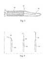
- FIG. 5shows a cross-sectional side and end view illustrating a guidewire probe according to an embodiment of the disclosed systems, devices, assemblies, probes, and methods wherein the antenna whip includes a combination whip where a helical coil may be connected to a linear whip antenna at multiple points.
- FIG. 6shows an embodiment in which a helical coil electronically connected to a linear whip antenna at a single point.
- FIG. 7shows an embodiment in which a helical coil alone includes a helical whip antenna.
- FIG. 8shows an embodiment in which a helical coil may be placed over a linear whip antenna without making an electrical connection between the two.
- FIG. 9shows an embodiment in which a core may be present inside a helical whip antenna.
- FIG. 10shows a representation of the receiving properties of a helical coil antenna.
- FIG. 11shows a potential embodiment of a helical whip antenna where the diameter of the coils decreases from the proximate to the distal end of the helical whip antenna.
- FIG. 12shows a potential embodiment of a helical whip antenna where the diameter of the coils increases from the proximate to the distal end of the helical whip antenna.
- FIG. 13shows a potential embodiment of a helical whip antenna where the diameter of the coils varies along the length of the helical coil antenna.
- FIG. 14shows an embodiment in which the probe shaft decreases in diameter at its distal end.
- FIG. 15shows an embodiment in which a second helical coil may be placed around the probe shaft and connected to the shielding.
- FIG. 16shows an embodiment in which a second helical coils may be used as shielding around various whip antennas of the disclosed systems, devices, assemblies, probes, and methods.
- FIG. 17shows a potential snap-on connector of the instant disclosed systems, devices, assemblies, probes, and methods.
- 17 Ashows the male connector portion and 17 B shows the female connector portion.
- FIG. 18shows a clip connector of the instant disclosed systems, devices, assemblies, probes, and methods. 18 A is in unlocked form and 18 B is in locked form.
- FIG. 19shows a screw-lock connector of the instant disclosed systems, devices, assemblies, probes, and methods.
- FIG. 20shows a screw style connector of the instant disclosed systems, devices, assemblies, probes, and methods.
- 20 Ashows the female portion and 20 B shows the male portion.
- FIGS. 21-23show alternate connectors whereby there is no direct electric contact between the male and female members of the connector.
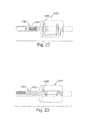
- FIGS. 24 and 25show different views of an embodiment including a vice-like connector between the connector portion and the mated connector portion and allow the guidewire to rotate within the connector.
- FIG. 26shows a potential design of an interface box of the instant disclosed systems, devices, assemblies, probes, and methods.
- FIG. 27shows a layout of a system of the instant disclosed systems, devices, assemblies, probes, and methods wherein the guidewire probe might be used.
- FIG. 28shows a potential embodiment of a helical whip antenna where the spacing between the coils varies along the length of the helical coil antenna.
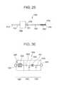
- FIG. 29shows a schematic diagram of an imaging probe system.
- FIG. 30shows a schematic diagram of the circuitry within the interface box.
- FIG. 30Ashows a schematic diagram of the circuitry within the interface box.
- FIG. 31shows the layers of the coaxial cable assembly.
- FIG. 32shows in more detail an embodiment of an imaging probe.
- FIG. 32Ashows detail of an embodiment of the shield layer.
- FIG. 33shows in more detail an imaging coil and flexible tip assembly.
- FIGS. 34A-Cshow cross-sections of an interface box.
- FIGS. 34 D-Eshow external views of an interface box.
- a loopless whip antennafor use as or with an imaging probe that is suitable for vascular procedures on human subjects in a conventional MRI machine designed for medical use.
- This descriptiondoes not, however, limit the scope of the disclosed systems, devices, assemblies, probes, and methods.
- the disclosed systems, devices, assemblies, probes, and methodscan have a wide variety of probes and MRI antennas whether a whip antenna or not and whether of looped, loopless or of other design which is suitable for use as an imaging probe as is understood in the art.
- the subject of the disclosed systems, devices, assemblies, probes, and methodsis also not limited to human beings but can be used on a variety of subjects where the use of an imaging probe is desired.
- an imaging probeis understood to include any device insertable into the subject of an intervention that provides MR images of an anatomic area internal to that subject.
- an imaging probemay be configured to be insertable into a vascular structure, as described below in more detail.
- An imaging probe for intravascular usemay produce images of the vascular structure within which it is situated, and may further provide images of tissues surrounding the vascular structure. These images may be used for further diagnostic or therapeutic purposes.
- an imaging probemay be dimensionally adapted to permit the direction of other interventional tools along it or over it.
- the imaging probemay be termed an imaging guidewire.
- an imaging guidewiremay be combined with a variety of interventional tools in the performance of diagnostic or therapeutic procedures, as will be appreciated by those of ordinary skill in the art.
- the disclosed systems, devices, assemblies, probes, and methodsare also not limited to a conventional MRI machine used medically but can be used in any type of scanning device that can measure magnetic resonance. Therefore, we use the term MRI machine to apply to any type of machine, device, system, means, or process which allows the detection of magnetic resonance in any type or state of matter, such device being currently known or later developed, whether for use on humans, non-human animals, other biological organisms, biological tissues or samples, or inorganic matter.
- Such an MRI machinemay be of any shape and for scanning any size subject or portion of a subject.
- guidewiresare also not limited to vascular interventions. Guidewires are commonly used in many non-vascular applications for the placement of various probes and catheters into the gastrointestinal (GI) tract, the biliary duct, the urethra, bladder, ureter and other orifices or surgical openings.
- GIgastrointestinal
- the disclosed systemsmay be adapted to a plurality of minimally invasive applications.
- Guidewires according to the present disclosed systems, devices, assemblies, probes, and methodsmay, in certain embodiments, be used for passage into and through the upper airway, trachea and bronchial tree.
- Examination of these structures using the disclosed systems, devices, assemblies, probes, and methodsmay be performed to detect abnormalities of the lungs or tracheobronchial tree, ideally at an early stage for early treatment.
- the early detection of a pre-malignant lesion in the tracheobronchial treecould permit early extirpation before an invasive cancer develops; even if an invasive cancer is detected, it may be possible to detect and treat these lesions at their earliest stages, before lymph node invasion or distant metastasis.
- the disclosed systems, devices, assemblies, probes, and methodsare applicable to any body lumen or body cavity wherein early detection of pre-malignant and malignant disease is desirable.
- these systems and methodscould be used for the evaluation of the esophagus, stomach and biliary tree to identify neoplasms and to distinguish benign from malignant tissue proliferation.
- these systems and methodscould be used for the evaluation of the colon and rectum to identify abnormalities and malignancies.
- These systems and methodscould also be used for the evaluation of the male and female urogenital systems, including bladder, urethra, prostate, uterus, cervix and ovary, to identify therein abnormalities and malignancies.
- the diagnostic function of the MRIwould be useful in the evaluation of any mucosal malignancy to identify how far through the wall of the affected organ the malignancy has invaded. It is understood in the art that extent of invasiveness into and through the wall, diagnosable by MRI, is an important characteristic of an intraluminal cancer.
- the diagnostic function of the MRI, as the probe is guided to the target tissue,may be combined with therapeutic interventions.
- a small lesion found within a body lumen using the disclosed systems, devices, assemblies, probes, and methodsmay be suitable for localized ablation, wherein the lesion's response to the delivery of radio frequency energy or other ablative energy can be monitored in near real time by the high resolution MRI as disclosed herein.
- the scale of the devices described hereinmay be dimensionally adaptable to a number of body cavities and lumens traditionally inaccessible to interventive methods known in the art.
- the eustachian tube, the nasal airways and the craniofacial sinusesmay all be accessible to a probe designed in accordance with the present disclosure.
- Using one of these orifices as an entryway into the craniofacial skeletonmay permit the diagnosis or evaluation of a variety of otolaryngological and neurological conditions with greater precision than is currently available using whole-patient CT or MRI.
- transsphenoid evaluation of intracranial or sellar lesionsmay be possible.
- the imaging of these lesions provided by the disclosed systems, devices, assemblies, probes, and methodsmay be combined with therapeutic techniques for extirpating or otherwise treating the lesion using minimally invasive technologies.
- an aneurysm of the Circle of Willis that is identified using high-resolution MRImay be suitable for clipping under MRI control using minimally invasive techniques.
- a pituitary tumorcan be evaluated for its extensiveness using these systems and methods, and its resection can be precisely monitored.
- Use of these systems and methodsmay also permit diagnosis of abnormalities in organs considered inaccessible to traditional monitoring methods.
- the pancreasmay be examined, using an embodiment of the disclosed systems, devices, assemblies, probes, and methods, permitting the early diagnosis of pancreatic lesions.
- embodiments of the disclosed systems, devices, assemblies, probes, and methodsmay be adapted for intracranial use, for the diagnosis of lesions of the central nervous system or for precise anatomic delineation thereof.
- Ablative techniquesmay be combined with these diagnostic modalities to permit treatment of abnormalities using embodiments of the disclosed systems, devices, assemblies, probes, and methods to help determine the extent of the pathology and to monitor the effectiveness of the ablation in removing the abnormality.
- Trigeminal neuralgiais an example of a condition where delineation of the relevant intracranial anatomy is vital for the identification of the neuroanatomical structures to be ablated or treated.
- MRI using the disclosed systems, devices, assemblies, probes, and methodsmay usefully help direct the surgeon to the precise tissues requiring treatment.
- MRI guidancemay be particularly valuable in determining the extensiveness of a lesion that is to be resected or biopsied.
- mediastinoscopyit may be difficult to distinguish between large blood-filled vessels and pathological lymph nodes, the latter being the target for the biopsy being performed. The operator performing the procedure must sample the pathological lymph nodes without damaging the large vessels in the area, an inadvertancy that can result in profound, even exsanguinating hemorrhage.
- MRI guidance according to these systems and methodscan not only distinguish among the various types of anatomic structures, but also can map out the extent of lymph node involvement and direct the operator towards those lymph nodes most likely to bear the abnormal tissue being sought.
- a number of applicationswill be readily apparent to practitioners of ordinary skill in the art, whereby a conventional endoscopy procedure combined with these systems and methods will permit the diagnostic evaluation of a tissue or organ within a body lumen or a body cavity.
- the intraperitoneal spacemay be usefully evaluated using these systems and methods, with access to this space being provided by laparoscopic instrumentation, and with MRI being used to approach and identify target tissues.
- Intraperitoneal diagnosis using these systems and methodsmay be helpful in diagnosis of various retroperitoneal lymphadenopathies, such as those indicative of lymphoma, or such as those indicative of spread from a malignant melanoma of the lower extremity.
- various retroperitoneal lymphadenopathiessuch as those indicative of lymphoma, or such as those indicative of spread from a malignant melanoma of the lower extremity.
- Other examplesmay be evident to ordinarily skilled practitioners in the medical arts.
- contrast agentsin addition to the systems and methods described herein may permit identification of tumors on the basis of their abnormal blood flow or metabolism. Contrast agents or other markers carried by body fluids may permit these systems and methods to be used for diagnosis of abnormal bleeding sites, such as occult gastrointestinal bleeding points or bleeding varices, situations where direct visual inspection of the lesion may have limited diagnostic or therapeutic value.
- the disclosed systems, devices, assemblies, probes, and methodsmay be used as a replacement for various ultrasound-guided techniques such as fertility procedures.
- the disclosed systems, devices, assemblies, probes, and methodsmay be adapted for screening procedures using probes dimensionally adapted for appropriate bodily orifices.
- these systems and methodsmay be useful in identifying and determining extensiveness of gynecological cancers, including cervical cancer, uterine cancer and ovarian cancer.
- Other applicationsshould become available to practitioners of ordinary skill in the art with no more than routine experimentation.
- the probe of the disclosed systems, devices, assemblies, probes, and methodscan be described and understood as having multiple different forms of antenna whip and design.
- the first of whichis depicted in FIG. 1 wherein the probe has a linear whip antenna 106 .
- the whiprefers to the antenna at the end of the probe which is a whip antenna.
- the whiphas a primarily unbent protrusion and is therefore called a linear whip antenna 106 .
- the probepreferably has a probe shaft 105 with a distal end 109 and a proximate end 111 .
- the probe shaftcan have multiple layers of different materials including a core 101 having at least one first electrically conducting component, a first insulator/dielectric 102 for providing insulation, a shielding 103 having at least one second conducting component, and an optional second insulator/dielectric 104 as shown in FIG. 2 .
- the linear whip antenna 106extends from the distal end 109 of the probe shaft 105 .
- a linear whip antenna 106does not have to be straight but may have a curve or slight hook at the end as is understood in the art to facilitate engagement of the device into complex vessels as shown in FIG. 3 .
- the linear whip antenna 106could be flexible or could be bent to form non-linear shapes as the probe was twisted through complicated pathways within the subject.
- the linear whip antennacan have a ribbon or paddle shape such as those shown in FIG. 16 .
- the core 101can have a super-elastic material such as the Tinol® range of materials (also known as Nitinol or NiTi).
- Super-elasticsgenerally have a titanium-nickel alloy and have many positive attributes for use as a base for the probes of the disclosed systems, devices, assemblies, probes, and methods.
- the MR properties of Nitinolare favorable due to the visibility with limited artifact.
- Super-elasticsmay be significantly deformed and still return to their original shape. Such deformation and “shape memory” can take place through actions based on changes in temperature.
- Super-elastic materialsare also known for high biocompatability and show good properties for use within biological organisms or matter.
- Super-elastics in the antenna designs of the disclosed systems, devices, assemblies, probes, and methodscould be of a variety of shapes including wire, ribbon, microtubing, sheets or any other form as is known to the art and can have Nitinol wire that can be plated with layers of gold-silver-gold, or layers of gold, silver or copper applied either singly or in combination.
- the core 101can alternatively have different materials, including, but not limited to, MR-compatible stainless steel, other metallic materials that are non-magnetic, non-metallic substances such as carbon, glass fiber, or polymer, that can be plated with a layer of a good RF conductor such as copper, silver, or gold either singly or in multiple layers, or any of the previous in any combination.
- the surfacecan be readily oxidized as is known to the art to provide the first insulator/dielectric 102 .
- the first insulator/dielectric 102 and the second insulator/dielectric 104may have any insulator/dielectric as is known to the art including any polymer, such as, but not limited to, an elastomeric grade PEBAX, Nylon, Teflon®, polyurethane, fluoroethylene polymer (FEP), or polyvinylidene fluoride (PVDF), or any combination of polymers with appropriate electrical properties.
- the insulator/dielectriccould also have aluminum oxide or any other nonpolymeric element or compound as would be understood by one of skill in the art.
- the thickness of the first insulator/dielectric 102 and the second optional insulator/dielectric 104can be determined so as to control the impedance of the cable formed.
- the impedancecan be in the range of 150 ohms to 10 ohms.
- the wirecan have a uniform impedance throughout the length or the impedance can vary with length, for instance, by having low impedance closer to the proximate end 111 as compared to the distal end 109 .
- the shielding layer 103may have any MR-compatible conductive material including, but not limited to, copper plated with silver, copper plated with gold, Nitinol plated with gold, conductive inks, conductive coatings or any of the previous in any combination.
- the shieldingcan be in the form of a braid, a mesh, or a continuous tubing such as, but not limited to, a gold-silver-gold plated Nitinol hypotube.
- the shieldingcan be continuous or coiled toward the distal end 109 and can extend beyond the distal end 109 of the probe shaft 105 or may be discontinued at the distal end 109 of the probe shaft 105 . Discontinuing the shielding can create a stronger signal from the antenna, but may create detrimental effects when the probe is used in a human body.
- the shielding 103can be added to the probe shaft in the form of a balun circuit as is understood in the art. This reduces the effect of induced currents due to external RF and magnetic fields.
- the tertiary shielding 451can be continuous or discontinuous. It can have capacitors connecting the discontinuous sections or it can be connected directly to the primary shielding 461 or connected to the primary shielding 461 with capacitors 471 or by any other method understood in the art, or by a series of balun circuits 139 as shown in FIG. 4 .
- a balun circuitis placed on the probe in a tuned form (also known as a zenooka circuit) as is known to the art.
- This tuned balun circuitcould help to increase the SNR performance and reduce the induced currents on the wire during an RF pulse transmission by any external RF coil (such as the transverse magnetic field in an MRI machine).
- This circuitmay also decrease the risk of possible excessive Ohmic heating from the presence of the probe inside the body.
- the second optional insulator/dielectric 104is desirable over the antenna whip as depicted in FIG. 2 so as not to insert a straight cylindrical segment of bare wire into the patient with direct blood and tissue contact.
- the problem with this solutionis that the optimal length of the whip portion of the device is determined based upon the operating electromagnetic wavelength in vivo which in turn depend upon the effective dielectric constant as experienced by the antenna. For the case of a bare wire loaded in water, this length is approximately 4-12 cm, which represents a reasonable length for in vivo use.
- a second insulator/dielectric 104decreases the effective dielectric constant, which in turn increases the operating wavelength and thus the optimal whip length from 4-12 cm to 30-100 cm for a dielectric with a dielectric constant of about 2 to 4.
- an alternative insulated whip designcould be desired when the antenna is insulated as is discussed below.
- covering the antenna with a second insulator/dielectric 104increases the diameter of the antenna making it increasingly difficult to insert in small vessels.
- the linear whip antenna 106has the narrowest possible diameter to allow such insertion.
- a typical assembly procedure for an MRI probecan involve the following steps. First, the first insulator/dielectric 102 is attached to a gold-silver-gold plated Nitinol core 101 . This can be done by means of extrusion, drawing, a heat shrink tubing, or any other method known to the art. Next, the shielding 103 is loaded on the assembly leaving a portion of the assembly exposed to act as the linear whip antenna 106 . This can be done by means of braiding, plating, painting, a hypotube, sputtering, or any other means known to the art. Alternatively, a metallic hypotube can be used instead of braiding to add mechanical stiffness to the probe shaft.
- the second insulator/dielectric 104is loaded on the probe shaft 105 .
- a connectorcan then be attached to the proximate end 111 of the probe shaft 105 to facilitate connecting to the interface circuitry to be connected to the MRI scanner.
- the connectorcan be any type as is known to the art, or could alternatively be any of the connectors described below.
- the connectorcan be replaced by mechanical forming of the proximal tip to enable attachment of a snap-fit connector or by any other means of connections or termination of the probe as would be known to one of skill in the art.
- An optional coating of lubricantmay further be added to the probe shaft 105 and/or antenna whip to reduce drag.
- the disclosed systems, devices, assemblies, probes, and methodscontemplate the manufacture of the linear whip antenna 106 and probe shaft 105 as a single piece as is described above.
- the probe shaft 105 and linear whip antenna 106could be constructed as two separate pieces and attached together by any means known to the art either permanently (including, but not limited to, use of welding, soldering and/or electrically conducting glue or epoxy) or removeably (including, but not limited to, a snap-on or locking connection).
- FIGS. 5 , 6 and 7show alternative embodiments of the disclosed systems, devices, assemblies, probes, and methods using a helical coil antenna that obtains through its shape the ability to be the same physical length as a linear whip antenna, while still maintaining the electrical length of a much longer linear whip and therefore having desirable properties even when shielded by a second insulator/dielectric 104 .
- FIGS. 5 and 6show a combination whip antenna 206 where a helical coil is placed over and electrically joined to a linear whip antenna 101 .
- FIG. 7shows a guidewire probe with a helical whip antenna 206 where the helical coil 208 has the antenna alone.
- Helically coiling the antennashortens the physical antenna length while still producing optimum performance. Covering the antenna with an insulator, increases the optimum antenna length because the insulator effects the ability of the antenna to detect signal. In this case, coiling the antenna can be used to compensate for this increase in optimum antenna length. That is, a coil of wire can have a longer piece of wire in a shorter physical form.
- a helical coil antennahas further mechanical advantages over a linear antenna.
- a coilis flexible and “springy” allowing it to navigate through complicated biological pathways without bending, kinking, or breaking, as opposed to a linear antenna which can have many of these problems since it is narrow and may have poor mechanical properties. Therefore, in one embodiment of the disclosed systems, devices, assemblies, probes, and methods, the helical coil is placed over a linear antenna, not necessarily to change signal, but to “superimpose” preferred mechanical properties on the linear antenna as exemplified in FIG. 8 .
- the helical coilalso provides for detection of magnetic resonance in multiple directions.
- the signal received by a linear antennais dependent upon the orientation of the antenna with respect to the main magnetic field as is known to the art.
- a linear antenna designbecomes bent or changes geometric planes, the sensitivity of the antenna and thus image quality can be degraded, with zero signal detected in some cases.
- the unique physical geometry of the helical coil antennaallows detection of radio frequencies from two orthogonal components of the processing transverse magnetization, which is known as quadrature detection. Quadrature designs are able to create a circularly polarized electric field that results in a 50% reduction in RF power deposition and up to a 40% increase in signal to noise ratio.
- the total polarization field (E) of a N turn normal mode helical antennais:
- E ⁇ and E ⁇are the electric fields produced by a small loop and short dipole respectively
- Nnumber of turns
- I 0initial current
- cspeed of propagation
- ⁇ 0permittivity constant
- ⁇wave number
- Dcoil diameter.
- Helical coil antennashave two distinct and very different operating modes depending upon, as shown in FIG. 10 , the physical dimensions of the windings and speed of wave propagation through the medium.
- the helical coil antennaoperates in an end fire or axial mode, where polarization occurs primarily along the axis of the helix as depicted in FIG. 10( b ). This is similar to the operation of the linear antenna.
- the helical antennaWhen D ⁇ and S ⁇ are much smaller than ⁇ , the helical antenna is said to operate in normal mode where polarization occurs orthogonal or broadside to the helical axis as shown in FIG. 10( c ) and described in equation (1). Since the RF frequencies used in MRI tend to be very long, normal mode operation is the standard for a probe of the disclosed systems, devices, assemblies, probes, and methods.
- FIGS. 5 and 6show a probe with a helical coil 208 on top of a linear whip antenna 106 . This creates a combination whip antenna 206 .
- the connection pointcould be at the distal end 215 of the linear whip antenna 106 instead of at the proximate end 223 as shown in FIG. 6 . This allows for both portions to act as antennas and can produce an antenna with higher SNR without increasing physical size significantly.
- a thin insulator 210may be placed between the linear whip antenna 106 and the helical coil 208 in any combination antenna 206 .
- the helical coil 208 and the linear whip antenna 106are not electrically connected to one other.
- the helical coil 208provides beneficial mechanical properties to the linear whip antenna 106 .
- itcan make the linear whip antenna 106 more rugged and more flexible allowing for better mechanical properties within the subject.
- the probe shaft 105can be built similarly to the probe shaft of FIG. 1 and all listed materials for the probe of FIG. 1 are also available for the probe of FIGS. 5 , 6 , and 8 .
- any probe shift 105 in any embodiment herein describedmay be constructed in a similar manner.
- the helical coil 208can be added to a preconstructed probe with a linear whip antenna 106 .
- the additioncan either complete the electrical connection to the helical coil 208 or not depending on the desired final probe.
- the probecan be manufactured with the helical coil 208 already attached to the probe in any configuration.
- the helical coil 208has the entire helical coil whip antenna 306 .
- the helical coil 208is electrically connected to the core 101 of the probe shaft 105 .
- the whipis entirely helically coiled.
- This configurationcan provide advantages in mechanical properties.
- the helical coil whip antenna 306can be physically shorter or narrower than the combination whip antennas 206 depicted in FIGS. 5 , 6 , and 8 without significant loss of electrical length.
- the helical coil whip antenna 306since the helical coil whip antenna 306 has no linear portions and is only coiled, it is more flexible than any of the other antennas allowing it to turn sharper corners in the subject. Finally, the helical coil whip antenna 306 is more deformable than any of the previous antenna designs which makes the antenna less likely to puncture vessel walls. If desired, the flexibility of this antenna can be adjusted by including a core component 217 attached to the distal end 109 of the probe shaft 105 if nonconducting or unattached if conducting, as shown in FIG. 9 . Core 217 need not extend to the distal end 415 of the helical coil whip antenna 306 .
- FIGS. 11 , 12 and 13depict alternative embodiments of the helical coil whip antenna 306 that can be used in place of the whip designs shown in FIGS. 7 and 9 .
- the helical coil whip antenna 306has been tapered with decreasing diameter towards the distal end 415 to vary the flexibility of the whip such that it is more flexible at the tip to negotiate blood vessels and the like.
- the helical coil whip antenna 306is tapered on the proximal end 515 to stiffen the flexibility at the distal end 415 .
- the helical whip antenna 306is tapered at both ends. The taper can be adjusted to provide the desired flexibility gradient.
- the tapercan also repeat at regular intervals (either smoothly or at a sudden transition) or coils of different diameters can be placed anywhere within the length of the helical coil whip antenna 306 .
- the distal end 109 of the probe shaft 105can be tapered to improve the transition between the probe shaft 105 and any type of whip antenna (a helical coil whip antenna 306 is shown) as shown in FIG. 14 .
- the spacing between the coilscan also be modified. As shown in FIG. 28 the spacing of the coils can be closer together at the proximate end 515 and further apart at the distal end 415 . This arrangement may allow the construction of a helical coil whip antenna that has greater electrical length but preserves the desired mechanical properties present in a looser packed coil. Alternatively to FIG. 28 , the coil spacing could be altered so that the spacing is tighter at the distal end 415 than the proximate end 515 , the coil spacing could follow any type of regular change from tighter to looser coils along its length, or the coil spacing could have coils of random spacing.
- the optimum coil lengthmay be preferably calculated or measured as the length that minimizes the real component of the impedance of the antenna as the impedance of the antenna is measured at the point where the shield ends. This length is usually around 0.25 or less times the electromagnetic wavelength of the RF MRI signal in the medium, but other lengths could be used as would be understood by one of skill in the art.
- FIG. 15shows yet another embodiment of the disclosed systems, devices, assemblies, probes, and methods
- a second helical coil 408is connected to the shielding 103 at point 513 of the probe shaft 105 to concentrate the MRI signal sensitivity to a narrow range.
- the second helical coil 408can also be connected to multiple points for multiple different electrical properties as would be understood by one of skill in the art.
- the shield 103is completely replaced by the second helical coil 408 which extends for the length of the shaft, insulated from the core 101 by dielectric 102 .
- These arrangementscan be used with any type of whip antenna including, but not limited to, those shown in FIG. 16 .
- a linear whip antenna 106as shown in FIG.
- a helical coil whip antenna 306 with a separation between the outer shield and whip as shown in FIG. 16Ba helical coil whip antenna 306 without a separation between the outer shield and whip as shown in FIG. 16C or an alternate combination whip with a linear extension 1601 attached to a helical coil whip antenna 306 as shown in FIG. 16D , as well as with any of the other antenna whip designs and herein disclosed or otherwise known to one of skill in the art.
- the second insulator/dielectric 104is extended over the second helical coil 408 so as to provide protection to the subject from the antenna's interaction with exposed body fluids, tissues, or other portions of the subject as is depicted in FIG. 16E .
- the second helical coil 408can also have any alterations of the coil's diameter or spacing along the second helical coil's 408 length as have been previously discussed with regards to the helical coil whip antenna 306 .
- connection between this electronic circuit and the probeis a further portion of the disclosed systems, devices, assemblies, probes, and methods because a standard RF BNC connector as is known to the art is not well suited for frequent connection and disconnection. In many current procedures where an MRI guidewire might be desired, the tools used as part of those procedures must be changeable without having to remove the guidewire from the subject.
- a connectoris used to make an electrical connection between the probe and a tuning/matching and decoupling circuit or interface box of the present disclosed systems, devices, assemblies, probes, and methods.
- This connectorconnects the interface to the antenna and can be removed and reinstalled as required during an interventional procedure to load and unload other interventional devices.
- FIGS. 17 through 25show some examples of connectors of the disclosed systems, devices, assemblies, probes, and methods which are discussed in detail below.
- FIG. 26shows one embodiment of an interface box for use between the MRI machine and the probe or guidewire of the disclosed systems, devices, assemblies, probes, and methods.
- One embodiment of the interface boxhas a shielded box 601 with two compartments 607 and 617 , separated by a partition 605 . In one embodiment, all components are non-magnetic.
- the probeattaches to coaxial connector 611 or another mating connector portion designed to attach to the connector portion of the probe.
- Coaxial connector 611can be insulated from the interface box 601 .
- the balancing of the dipole 611is accomplished by capacitor 613 and coil 615 .
- Coil 615 in one embodimentis a short length (5-10 cm) of 1 mm diameter solid-shield, 50 ohm coaxial cable, which is wound into a coil, increasing the inductance of both the center conductor as well as the shield.
- itcan be important to present a high impedance to current flow in the shielding 103 of the probe near the interface box 601 .
- This high impedanceis accomplished by tuning the LC circuit formed by capacitor 613 and the inductance of the shield of coil 615 .
- capacitor 613is selected such that the impedance of the network having capacitor 613 and coil 615 matches the impedance of the shielding 103 of the probe.
- the shield portion of the coaxial cable that forms coil 615can be electrically connected to the partition 605 of the interface box 601 as shown in FIG. 26 .
- the center conductor of the coaxial cable that forms the coil 615feeds through the partition 605 in the interface box 601 .
- the inductance of the center conductor of the coil 615 , and capacitor 613form a tuned circuit that can decouple the probe from the imaging pulses of the MRI machine connected at -axial connector 619 (these imaging pulses usually occur at 63.9 MHz).
- Capacitor 621can be tuned to maximize probe impedance when PIN diode 623 is turned on during imaging pulses. PIN diode 623 is turned on by a DC level being applied to co-axial connector 619 by the MRI scanner during MRI pulse transmission.
- the probecan be tuned to match the generally 50 Ohm impedance of the MRI scanner amplifier by the network of inductor 625 and capacitor 627 .
- This tuningcan be accomplished by connecting a network analyzer to coaxial connector 617 and varying the value of the capacitor 627 until the measured impedance is the commonly desired 50 Ohms at 63.9 MHz.
- the end of the antennacan have a connector portion that allows radio frequency signals to propagate from the scanner to the antenna and vice versa by connecting the connector portion to a mated connector portion.
- This connectorcan be a standard BNC connector or one of the special miniaturized connectors shown in FIGS. 17 through 25 .
- the connectorsallow for direct insertion of the probe into interventional devices such as balloon angioplasty catheter, stent placement devices.
- the connector diametershould be no larger than the probe diameter.
- Standard connector sizesare often larger than the probe diameter and therefore do not allow for rapid exchanging of interventional devices over the probe. To overcome this difficulty, we show eight different connector configurations. Although many other designs are possible, the most important feature of these designs are that the diameter of the connector portion on the probe is not significantly larger than the diameter of the probe.
- the connectors shown in FIGS. 17 through 20 , 24 , and 25enable direct electrical contact between the conductors (shield and inner conductor of core) whereas the connectors shown in FIGS. 19-23 have no direct electrical contact.
- FIG. 17shows a snap-on connector.
- the connector at FIG. 17Ais the male connector portion. Its diameter is smaller or the same size as the diameter of the guidewire probe.
- FIG. 17Bis the female mated connector portion. They are connected to one other with a small amount of pressure in the direction along the length of the connector and removed easily by pulling the connectors apart.
- FIG. 18shows a clip connector.
- the male connector portion's 1002 diameteris not larger than the diameter of the probe.
- a clip lock mechanism, 1006the female mated connector portion 1003 is connected to the male connector portion 1002 .
- the mechanism shown by FIG. 18enables free rotation of the connector. This enables the user to freely rotate the probe while it is connected.
- 1004shows a coaxial cable connecting the interface box 1005 to the mated connector portion.
- FIGS. 24 and 25show an alternative design of this type of connector wherein a vice-like connection is employed instead of the clip. Again this design allows for the probe to rotate freely while it is connected.
- FIG. 19has the screw 1007 on the female mated connector portion that is an alternative to the clip lock mechanism, 1006 shown in FIG. 18 .
- FIG. 20shows another type of screw connector.
- FIG. 20Ais the female connector portion that is a part of the guidewire probe.
- the male mated connector portion shown in FIG. 20Bcan be connected to a coaxial cable that leads to the interface box.
- FIGS. 17 through 20One problem with the connectors shown in FIGS. 17 through 20 is difficulty in using in a wet environment. When the connectors are wet or have blood or other body fluids on them, their performance may degrade. Therefore, a connector was designed that can be used in wet environment. The connectors shown in FIGS. 21-23 do not require direct electrical contact between the two connector portions.
- FIG. 21shows a solenoidal coil 2005 inside both female and male connectors portions.
- the male connector portionsnaps in the female mated connector portion 2003 but the electrical wires are not touching one other.
- the signalis transmitted from one to the other by electromagnetic waves.
- FIG. 22shows a coaxial cable with extended inner conductor 2105 as the mated connector portion 2103 and an opposed solenoidal coil 2107 as the connector portion 2101 on the guidewire probe.
- FIG. 23shows a loop coil 2305 in both ends of the connector.
- the male connector portion 2301snaps on the female mated connector portion 2303 .
- the electromagnetic wavesare transmitted from one coil to the other enabling connection.
- FIGS. 21-23One further advantage of using these connectors are the isolation of the circuits. Any direct current from one connector should typically not appear on the other.
- FIG. 27shows one potential layout of a system whereby a probe could be used.
- the subject 901is shown within the MRI machine 903 .
- the probe 3005has been inserted into the subject 901 .
- the monitor 905shows an MRI 907 including the probe 3005 and the surrounding biological tissue 909 .
- the probe 105is connected to the interface box 1005 through a connector 1111 that allows an operator to load or unload tools without removing the probe 3005 from the subject 901 .
- the interface box 1005is connected to the MRI machine 903 allowing the MRI machine 903 to use the probe 3005 as an active antenna in the subject 901 .
- FIG. 29shows an embodiment of an imaging probe system 1500 that may be configured for use in the vascular system.
- the imaging probe system 1500can be dimensionally adapted for intravascular use, with an outer diameter in one embodiment in the range of 0.025-0.035′′, for example. 0.032′′, and with an outer diameter in another embodiment of in the range of 0.014-0.018′′, for example, 0.014′′.
- the probemay also be dimensionally adapted for insertion into other anatomical features.
- a probe for esophageal insertioncould have an outer diameter in the range of about 3 to about 30 French, preferably about 9 French.
- a probe for transrectal insertioncan have an outer diameter in the range of about 0.5 French to about 60 French, preferably about 15 French.
- a probe for prostate imagingcan have an outer diameter in the range of about 0.5 to about 10 French, preferably about 10 French.
- a probe for transvaginal insertioncan have an outer diameter in the range from about 0.5 to about 60 French, preferably about 9 to 14 French.
- a probe for gastrointestinal insertioncan have an outer diameter in the range from about 1 French to about 20 French, preferably about 15 to 17 French.
- a probe for transurethral insertioncan have an outer diameter of about 6 to 17 French, preferably about 13 French.
- a probe for fallopian tube insertioncan have an outer diameter in the range from about 1 French to about 6 French, preferably about 1 to 3 French.
- the imaging probe system 1500may be introduced into the body of a subject directly into the vascular system, through, for example, the femoral artery or vein using a standard introducer. The imaging probe system 1500 may then be advanced through thevascular system to the region of interest either under fluoroscopic or MR guidance.
- the imaging probe 1500has a proximal end 1501 attachable to an interface box 1508 , which in turn is attachable to an MRI machine (not shown).
- the imaging probe 1500further has a distal end 1503 suitable for advancing through the vascular system of a subject.
- an imaging probe 1500 for intravascular usemay include an imaging coil 1502 in electrical communication proximally with a modified coaxial cable 1504 .
- the modified coaxial cable 1504 in electrical communication with the imaging coil 1502has a loopless antenna.
- the imaging coil 1502 and the insulating shielding of the coaxial cable 1504form a closed RF circuit, and RF signals generated by the hydrogen protons in the water molecule during MR scanning are collected by the imaging coil 1502 and then transmitted to the MR scanner through the coaxial cable 1504 and interface box 1508 , as will be described in more detail below.
- the coaxial cable 1504may include a conductor core sandwiched concentrically in layers of insulation/dielectric, conductive shielding and dielectric/insulation respectively.
- the construction of the imaging probe 1500may include a simple coaxial cable 1504 with its top layers of insulation and shielding removed in certain sections, as will be described in more detail below. In those sections where the top layers of insulation and shielding have been removed, the central conductor of the coaxial cable 1504 can be exposed. The exposed central conductor may then be attached to the imaging coil 1502 to maintain electrical communication therewith.
- the imaging coil 1502may be made from a wire wound on a mandrel, for example a gold-platinum-iridium winding wire.
- the imaging coil 1502is disposed distally on the imaging probe 1500 .
- the imaging coil 1502serves to gather the RF signal.
- the imaging coil 1502includes a specific length of gold-platinum-iridium wire wound into a spring with a prescribed pitch.
- the wirecan be a wound wire.
- the wound wirecan have a diameter of about 0.003 inches.
- the pitch of the windingcan be in the range of about 0.004 inches to about 0.015 inches. In an embodiment, the pitch can be about 0.012 inches.
- the imaging coil 1502can be positioned over, covering, or surrounding the insulated conductor core of the coaxial cable 1504 .
- the conductor coremay be made from a Nitinol wire plated with gold-silver-gold and then covered with a thin insulating layer of polymeric FEP.
- the polymeric layerinsures complete electrical insulation between the core and the imaging coil 1502 except at the proximal end of the imaging coil 1502 where it has been attached to the core in electrical communication therewith.
- the imaging coil 1502 lengthis about 0.25 times the wavelength in the medium, which is a complex function of various parameters such as the dielectric constant of the insulator, the thickness of the primary insulator, the frequency, and the electrical properties of the environment around the antenna.
- the length of the imaging coil 1502 which acts as an RF antennacan be straight but is coiled in this case.
- the coil shapemay help intensify the signal near the imaging coil 1502 .
- the coil shapecan be straight, ground, wound, braided, multiple pitches, combinations of these, and other shapes known in the art.
- the imaging coilcan include a solid object, such as a core or a hypotube. There need not be insulation between the imaging coil and the corewire. A plastic could be extruded over the imaging coil. A lubricious coating could be applied to the plastic.
- the coaxial cable 1504connects the proximal end 1501 of the imaging probe 1500 to an interface box 1508 .
- a connectorsuch as a Suhner MMCX connector.
- the interface box 1508in turn connects the probe 1500 to the MRI scanner (not shown).
- An extension cable 1510 with a connector such as a BNC connector 1512may provide the connection between the interface box 1508 and its contained circuits and the MRI scanner (not shown).
- the circuitry housed in the interface box 1508is described below in more detail.
- a flexible tip 1514is attached at the distal end of the imaging probe system 1500 distal to the imaging coil 1502 .
- the flexible tip 1514may have a spring.
- the flexible tip 1514may be attached to the distal end of the coaxial cable 1504 .
- the flexible tip 1514will be described in more detail below.
- FIG. 30provides a diagram of the circuitry within the interface box 1508 .
- Providing attachment between the interface box 1508 and the proximal end of the coaxial cable (not shown)may be a BNC connector 1518 .
- In electrical communication with the imaging probe (not shown)are three circuits, a tuning-matching circuit 1520 , a decoupling circuit 1522 and a balun circuit 1524 .
- the imaging probe (not shown)may be connected to the interface box 1508 , and the interface box 1508 may further be connected to the appropriate coil port of the MRI scanner using a 50-200 cm long RGO58 coaxial cable with BNC connectors.
- a ground isolated Micro BNC (MMCX) connector 1531 or any other suitable connectorprovides electrical communication between the circuits in the interface box 1508 and the coaxial cable (not shown) attaching the interface box circuits to the MRI machine (not shown).
- MMCXMicro BNC
- a cable accessory to perform these functionsmay be added to the system described herein, as will be familiar to practitioners of ordinary skill in the art.
- Circuits in the interface box 1508perform three functions.
- the tuning-matching circuit 1520matches the impedance of the antenna/cable to the input of the scanner to optimize performance.
- the decoupling circuit 1522detunes the imaging probe during scanner coil transmit, using DC current supplied through the scanner connection to prevent heating.
- the balun circuit 1524prevents excess currents from being induced in the scanner.
- the arrangement of the circuits within the interface box 1508represent an exemplary embodiment thereof. It will be understood by those of ordinary skill that some modifications in interface circuitry may be required for different commercially available MR scanner models.
- the underlying principle of operation for the decoupling circuit 1522may be explained as follows: the MRI signals are excited in the patient's tissue by the MRI scanner's transmitter coil; this transmission may induce a current in the imaging probe during excitation, which could result in the production of heat.
- the decoupling circuit 1522allows this induced current to be shorted out.
- the decoupling circuit 1522includes a capacitor 1523 and a diode 1525 .
- the diode 1525 in the decoupling circuit 1522is activated by a standard low voltage signal provided by the scanner during MR transmission.
- the DC current generated by the scanneractivates the diode 1525 which in turn grounds the DC current, preventing the imaging probe from being exposed to the full current and thus reduces heating.
- the diode 1525is not active and the circuit functions normally.
- the tuning-matching circuit 1520includes a capacitor 1519 and an inductor 1521 in parallel to match the impedance of the entire circuit to 50 ohms, the input impedance required by the preamplifier of the scanner.
- the balun circuit 1524has a rigid coaxial cable inductor coil 1526 and a capacitor 1527 connecting the ground to the case of the interface box 1508 .
- the values of the capacitors described above and the inductor 1521may be determined on a network analyzer for the completed imaging probe system at the time of manufacture.
- FIG. 30Ashows a another schematic diagram of an exemplary embodiment of an interface 1508 ′. It may include a balun circuit 1524 having a capacitor 1527 and an inductor 1526 , a decoupling circuit 1522 , having a capacitor 1523 and a diode 1525 , and a tuning/matching circuit 1520 , having a capacitor 1519 and an inductor 1521 .
- Capacitor 1527may be a porcelain capacitor and may have a capacitance of about 39 picoFarads (pF).
- Inductor 1521may be a tunable inductor and may have an inductance of about 198 nanoHenrys (nH).
- Capacitor 1523may be a porcelain capacitor and may have a capacitance of about 100 pF.
- Diode 1525may be a PIN diode.
- Capacitor 1519may have a capacitance of about 22 pF.
- the interface 1508 ′may further include a proximal connector 1531 and a distal connector 1518 , as described above.
- the interfacemay further include a variable capacitor 1528 .
- the variable capacitor 1528facilitates fine adjustment of the tuning/matching circuit 1520 .
- the variable capacitor 1528may be a ceramic capacitor and may be variable in the range of about 5.5 pF to about 30 pF.
- FIGS. 34A-Edepicts various views of an exemplary embodiment of an interface box 3400 .
- FIG. 34Ashows a perspective view of the interface box 3400 .
- FIG. 34Bshows a side view.
- the proximal connector 1531emerges from one side of the interface box 3400
- the distal connector 1518emerges from an opposing side.
- FIG. 34Cdepicts a top cross sectional side view of the interface box 3400 .
- the inner surface 3402 of the box 3400may have a shield coating.
- the shield coatingcan effect a ⁇ 50 dB shielding at a predetermined frequency, such as 63.86 MHz.
- the box 3400may have a proximal aperture 3406 for the proximal connector (not shown) and a distal aperture 3404 for the distal connector (not shown).
- the shield coatingmay be applied up to the edge of one or both apertures 3404 , 3406 , or can be masked in areas surrounding one or both apertures 3404 , 3406 .
- FIG. 34Ddepicts a side cross sectional view through cut line B of FIG. 34C .
- Aperture 3404is positioned on a side of box 3400 .
- the box 3400may have a lid section 3410 and a base section 3408 .
- FIG. 34Edepicts a side cross-sectional view through cut line A of FIG. 34C .
- Aperture 3406is positioned on a side of box 3400 .
- FIG. 31shows in more detail a coaxial cable assembly 1504 included in the previously-described imaging probe system.
- the coaxial cable 1504 and its relation to the imaging probe systemwill also be described in more detail below.
- the coaxial cable 1504has a core 1550 made of a non-ferromagnetic conductive material, for example, Nitinol plated with precious metal. The plating may provide multiple layers of different metals, for example gold-silver-gold. Other materials for the core 1550 with appropriate properties may readily be envisioned by practitioners of ordinary skill.
- the core 1550may have a diameter in the range of up to about 0.014 inches, preferably 0.0085 inches and may be taper ground at its distal tip 1552 . Alternate configurations of the distal tip 1552 may also be provided, for example, barrel grinding or plunge grinding.
- a primary insulation layer 1554covers the core 1550 except where the primary insulation layer 1554 has been removed to expose the underlying core 1550 .
- the primary insulation layer 1554may use a plastic material such as FEP or another suitable insulator.
- a first and a second bare area, 1558 and 1560 respectively,are shown where the primary insulation layer 1554 is absent.
- the primary insulation layer 1554can be removed to create either or both bare areas. Removal may be accomplished by using a razor blade or a similar or similarly functioning tool.
- the bare areasmay also be created by not applying insulation in the regions of the bare areas or by applying insulation discontinuously along the core.
- a distal coaxial cable segment 1566where the primary insulation 1554 covers the core 1550 .
- the imaging coilSurrounding this distal coaxial cable segment 1566 is the imaging coil (not shown) in the complete imaging probe system.
- the first bare area 1558is also termed the joining segment.
- This coaxial shield layer 1564may be made of Nitinol or another suitable material. In one embodiment, a Nitinol hypotube is used with a diameter of 0.010-0.035′′ for an imaging probe with a substantially similar diameter. Additional layers may cover the coaxial shield layer 1564 . For example, gold or other precious metal plating may cover the coaxial shield layer 1564 along some or all of the proximal shaft 1562 .
- approximately 2 cm of the proximal end 1568 of the coaxial shield layer 1564may be goldplated, or gold plating may be extended more distally along the coaxial shield layer 1564 , as will be appreciated by practitioners of ordinary skill in the art, for the purpose, for example, of increasing conductivity of the loopless antenna. Goldplating can facilitate attachment of a connector.
- FIG. 32depicts in more detail an embodiment of an imaging probe 1500 that can be adapted for intravascular and other uses.
- the proximal shaft 1562includes a coaxial cable 1504 , for example a coaxial cable described with reference to FIG. 31 .
- the proximal shaftmay also include an extended flexible shield or proximal spring assembly 1580 .
- the Nitinol hypotubing of the coaxial shield layer 1564may be heat treated to increase its flexibility and a MP35N spring may be soldered to the distal end of the coaxial shield layer 1564 to form the proximal spring assembly 1580 .
- the proximal spring assembly 1580may be joined to the coaxial shield layer 1564 by a conductive epoxy, laserweld or solder joint, as will be understood by those of ordinary skill in the art.
- the proximal spring assembly 1580may combine with the coaxial shield layer 1564 to act as a contiguous coaxial shield while providing optimal mechanical characteristics in that region.
- the combination of the heat treated hypotube and the MP35N springacts as a strain relief to improve the transition from the hypotube to the inner core. In this arrangement, there is no significant loss to the electrical properties with this improved transition.
- the proximal spring assembly 1580may be fabricated from a variety of materials, in one embodiment using Tantalum or MP35N, for example using a 0.003 in. round winding wire that may be stacked.
- the proximal spring assembly 1580may replace distally the coaxial shield layer 1564 that is fabricated from, for example, a Nitinol hypotube. Alternatively, the proximal spring assembly 1580 may be omitted, so that the coaxial shield layer 1564 continues uninterrupted along the entire length of the proximal shaft 1562 .
- the primary insulator 1554may be attached to the core 1550 , for example, a gold-silver-gold plated Nitinol wire. This can be done by means of extrusion, drawing, a heat shrink tubing, or another method known to the art.
- the conductive shielding 1564may be loaded on the core-insulator assembly in the proximal sections. This can be done by means of braiding, plating, painting, depositing, sputtering, etc.
- a metallic hypotube fabricated from a material like Nitinolcan be used instead of braiding to add mechanical stiffness.
- the Nitinol hypotubemay be heat-treated over an area at its distal end or modified in other ways familiar to artisans for increasing flexibility of the hypotube as it approaches the transition area with the spring.
- An outer insulating layer 1584may be used to cover the entire assembly.
- FIG. 32further shows the imaging coil 1502 coiled around the distal coaxial cable segment 1566 (shown in FIG. 31 ).
- the imaging coil 1502is an electrical communication with the core 1550 at the first bare area 1558 by virtue of a solder junction 1582 .
- Dimensions of the imaging coil 1502may also be modified, so that the length may range up to 12 centimeters and the pitch may be increased up to about twice the current one.
- the imaging coilcan have a length of about 6 inches.
- Pitchmay be selected in association with selection of length dimension so as to obtain a total length for the imaging coil of about 1 ⁇ 4 ⁇ , a length desirable for minimizing noise resistance and heating, where ⁇ is the wavelength of the magnetic resonance signal when the imaging probe is in vivo or in a sample.
- An insulating coating layer 1584extends along the proximal shaft 1562 of the imaging probe 1500 and may extend distally to cover the imaging coil 1502 until it encounters an adhesive seal (not shown in this figure), depicted in FIG. 33 . Distal to the adhesive seal (not shown), an adhesive joint 1588 may attach the spring tip 1514 to the core 1550 and to the primary insulation layer 1554 .
- the spring tip 1514is affixed distal to the imaging coil 1502 as described in more detail below at an adhesive joint made, for example, from epoxy.
- a BNC connector 1512 or another suitable coaxial connectorprovides electrical connection between the imaging probe system 1500 and the interface box (not shown) and further provides electrical connection between the core 1550 and the coaxial shield layer 1564 at the proximal end 1501 .
- cover layer 1584External to the coaxial shield layer 1564 may be a coating of cover layer 1584 , made, for example, from silicone or polyethylene terephthalate (PET), to protect the underlying materials from contact with body fluids. Additionally, a lubricious coating may be provided overlying the coating layer 1584 .
- the coating layer 1584may extend along a preselected length of the imaging probe 1500 , for example, from the adhesive junction 1588 to a proximal portion of the proximal shaft 1564 at a specified distance from the connector 1512 .
- FIG. 32Adepicts an embodiment of a probe having a shield layer 1564 with a distal end 1564 a , a modified shield layer 1565 with a distal end 1565 a and attached to the distal end 1564 a of the shield layer 1564 , and a joint 1598 connecting the distal end 1565 a of the modified shield layer 1565 to the proximal spring assembly 1580 .
- the joint 1598may be a conductive joint.
- the distal end 1580 a of the proximal spring assembly 1580may be joined to an imaging coil (not shown) by an adhesion point (not shown). The adhesion point may electrically insulate the proximal spring assembly 1580 from the imaging coil.
- the modified shield layer 1565may be, e.g., a heat-treated Nitinol hypotube.
- the modified shield layer 1565may provide a region of stiffness transition, so that the change in stiffness between the region of the shield layer 1564 and the region of the coil or the spring tip is gradual.
- Other compositions of the modified shield layerare discussed above.
- the thickness of the coremay be stepped up to help lessen potentially abrupt changes in stiffness.
- the shield layer 1564may include a series of telescoped layers (not shown), progressively decreasing in diameter distally. Such an arrangement can lessen abrupt changes in stiffness.
- FIG. 33depicts in more detail a spring tip assembly 1600 affixed to the imaging probe 1500 at the latter's distal end 1503 .
- the spring tip assembly 1600may provide flexibility at the distalmost end of the imaging probe 1500 so that the probe may advance more readily through tortuous regions of the vascular anatomy.
- the spring tip assembly 1600may also have an effect on breaking up standing waves to decrease heating.
- the spring tip assembly 1600includes a spring tip 1514 that is affixed to the distal end 1503 of the imaging probe 1500 .
- the spring tip 1514may be affixed proximally by means of an adhesive joint 1588 made from an electrically isolating material such as epoxy that prevents electrical conduction between the spring tip 1514 and the imaging coil 1502 or the core 1550 while attaching the spring tip 1514 to the core 1550 , the imaging coil 1502 , the shield layer 1564 , or the insulating layer 1584 .
- the adhesive joint 1588may further attach a ribbon 1602 to both the core 1550 and to the spring tip 1514 .
- the ribbon 1602may extend distally through the coils of the spring tip 1514 .
- the ribbon 1602is flat and is made of MP35N.
- a distal joint 1604for example a solder-braze joint, affixes the spring tip 1514 to the ribbon 1602 -distally and further seals the end of the spring tip 1514 .
- the spring tip 1514may be made from a gold-platinum-iridium winding wire 0.003 inches in diameter wound stacked except at joints 1558 and 1602 .
- a layer of outer coating 1584may cover the spring tip assembly 1600 .
- An epoxy adhesive 1608seals the imaging coil 1502 , the core 1550 and the coating layer 1584 .
- a solder junction 1582attaches the imaging coil 1502 to the core 1550 and provides electrical communication between the two.
- the primary insulation 1564covers the core 1550 and isolates it from the imaging coil 1502 .
- the spring tip 1514may be made from approximately 0.003 inch round winding wire stacked.
- Materialssuch as tantalum may be used or alloys such as a gold-platinum, MP35N or L605. Stiffness of the spring may be varied by changing materials and altering the arrangement of materials with treatments such as heat treatment, with changing the geometric shapes, with setting up telescoping tubes, and with other similar arrangements.
- the distal spring assembly 1600may be attached with conductive epoxy or adhesives, ultrasonic welding, mechanical attachment, soldering or laser welding.
- gadoliniummay be used in the coating of the guidewire, either with silicone or with a hydrophilic substance, permitting better magnetic resonance tracking of the wire.
- the imaging probemay include other features such as an extended flexible spring shielding, a longer overall length, a detachable connector with an extendable back end for balloon or guide exchanges, or a connector permitting distal spring change, as will be apparent to those of ordinary skill in the art.
- the distal spring areacould have a flatdropped isolated core or ribbon to provide a stiffness transition top the tip.
Landscapes
- Physics & Mathematics (AREA)
- Condensed Matter Physics & Semiconductors (AREA)
- General Physics & Mathematics (AREA)
- Health & Medical Sciences (AREA)
- General Health & Medical Sciences (AREA)
- Pathology (AREA)
- Magnetic Resonance Imaging Apparatus (AREA)
Abstract
Description
where: Eθ and Eφ are the electric fields produced by a small loop and short dipole respectively, N=number of turns, I0=initial current, c=speed of propagation, ∈0=permittivity constant, β=wave number, D=coil diameter. Note that the Eθ and Eφ components are in both space and time quadrature, resulting in an elliptical polarization field. In addition to these very important advantages, such a design allows the imaging capabilities of the device to be independent of spatial orientation and therefore it can be used in any vessel or other area in the body.
Claims (26)
Priority Applications (1)
| Application Number | Priority Date | Filing Date | Title |
|---|---|---|---|
| US10/123,065US7848788B2 (en) | 1999-04-15 | 2002-04-11 | Magnetic resonance imaging probe |
Applications Claiming Priority (4)
| Application Number | Priority Date | Filing Date | Title |
|---|---|---|---|
| US12936499P | 1999-04-15 | 1999-04-15 | |
| US09/536,090US6675033B1 (en) | 1999-04-15 | 2000-03-24 | Magnetic resonance imaging guidewire probe |
| US28299301P | 2001-04-11 | 2001-04-11 | |
| US10/123,065US7848788B2 (en) | 1999-04-15 | 2002-04-11 | Magnetic resonance imaging probe |
Related Parent Applications (1)
| Application Number | Title | Priority Date | Filing Date |
|---|---|---|---|
| US09/536,090Continuation-In-PartUS6675033B1 (en) | 1996-04-25 | 2000-03-24 | Magnetic resonance imaging guidewire probe |
Publications (2)
| Publication Number | Publication Date |
|---|---|
| US20030028095A1 US20030028095A1 (en) | 2003-02-06 |
| US7848788B2true US7848788B2 (en) | 2010-12-07 |
Family
ID=27383870
Family Applications (1)
| Application Number | Title | Priority Date | Filing Date |
|---|---|---|---|
| US10/123,065Active2026-04-11US7848788B2 (en) | 1999-04-15 | 2002-04-11 | Magnetic resonance imaging probe |
Country Status (1)
| Country | Link |
|---|---|
| US (1) | US7848788B2 (en) |
Cited By (28)
| Publication number | Priority date | Publication date | Assignee | Title |
|---|---|---|---|---|
| US20100204759A1 (en)* | 2006-06-09 | 2010-08-12 | Christman Timothy J | Systems for enabling telemetry in an implantable medical device |
| US8257302B2 (en)* | 2005-05-10 | 2012-09-04 | Corindus, Inc. | User interface for remote control catheterization |
| US20130009840A1 (en)* | 2010-03-24 | 2013-01-10 | Hytera Communications Corp., Ltd. | Whip dual-band antenna |
| US8364279B2 (en) | 2008-09-25 | 2013-01-29 | Boston Scientific Neuromodulation Corporation | Electrical stimulation leads having RF compatibility and methods of use and manufacture |
| US8369961B2 (en) | 2006-06-09 | 2013-02-05 | Cardiac Pacemakers, Inc. | Multi-antenna for an implantable medical device |
| US8480618B2 (en) | 2008-05-06 | 2013-07-09 | Corindus Inc. | Catheter system |
| US20130282088A1 (en)* | 2012-04-19 | 2013-10-24 | Medtronic, Inc. | Medical Leads Having Forced Strain Relief Loops |
| US8694157B2 (en) | 2008-08-29 | 2014-04-08 | Corindus, Inc. | Catheter control system and graphical user interface |
| US20140171933A1 (en)* | 2012-12-13 | 2014-06-19 | David C. Gross | Resonating radio frequency ablation device |
| US8790297B2 (en) | 2009-03-18 | 2014-07-29 | Corindus, Inc. | Remote catheter system with steerable catheter |
| US8979871B2 (en) | 2009-08-13 | 2015-03-17 | Monteris Medical Corporation | Image-guided therapy of a tissue |
| US8983574B2 (en) | 2009-11-17 | 2015-03-17 | The Brigham And Women's Hospital | Catheter device with local magnetic resonance imaging coil and methods for use thereof |
| US9220568B2 (en) | 2009-10-12 | 2015-12-29 | Corindus Inc. | Catheter system with percutaneous device movement algorithm |
| US9259290B2 (en) | 2009-06-08 | 2016-02-16 | MRI Interventions, Inc. | MRI-guided surgical systems with proximity alerts |
| US9333038B2 (en) | 2000-06-15 | 2016-05-10 | Monteris Medical Corporation | Hyperthermia treatment and probe therefore |
| US9433383B2 (en) | 2014-03-18 | 2016-09-06 | Monteris Medical Corporation | Image-guided therapy of a tissue |
| US20160320463A1 (en)* | 2013-12-13 | 2016-11-03 | Koninklijke Philips N.V. | Low cost magnetic resonance safe touchscreen display |
| US9504484B2 (en) | 2014-03-18 | 2016-11-29 | Monteris Medical Corporation | Image-guided therapy of a tissue |
| WO2017142698A1 (en) | 2016-02-17 | 2017-08-24 | MRI Interventions, Inc. | Intrabody surgical fluid transfer assemblies with adjustable exposed cannula to needle tip length, related systems and methods |
| US9782581B2 (en) | 2014-06-27 | 2017-10-10 | Boston Scientific Neuromodulation Corporation | Methods and systems for electrical stimulation including a shielded sheath |
| US9782582B2 (en) | 2015-03-27 | 2017-10-10 | Boston Scientific Neuromodulation Corporation | Systems and methods for making and using electrical stimulation systems to reduce RF-induced tissue heating |
| US9833293B2 (en) | 2010-09-17 | 2017-12-05 | Corindus, Inc. | Robotic catheter system |
| US20180071491A1 (en)* | 2014-10-20 | 2018-03-15 | Medtronic Cryocath Lp | Centering coiled guide |
| US9962229B2 (en) | 2009-10-12 | 2018-05-08 | Corindus, Inc. | System and method for navigating a guide wire |
| US10173055B2 (en) | 2015-04-30 | 2019-01-08 | Boston Scientific Neuromodulation Corporaation | Electrical stimulation leads and systems having a RF shield along at least the lead and methods of making and using |
| US10327830B2 (en) | 2015-04-01 | 2019-06-25 | Monteris Medical Corporation | Cryotherapy, thermal therapy, temperature modulation therapy, and probe apparatus therefor |
| US10675113B2 (en) | 2014-03-18 | 2020-06-09 | Monteris Medical Corporation | Automated therapy of a three-dimensional tissue region |
| US11918314B2 (en) | 2009-10-12 | 2024-03-05 | Corindus, Inc. | System and method for navigating a guide wire |
Families Citing this family (93)
| Publication number | Priority date | Publication date | Assignee | Title |
|---|---|---|---|---|
| US6898454B2 (en) | 1996-04-25 | 2005-05-24 | The Johns Hopkins University | Systems and methods for evaluating the urethra and the periurethral tissues |
| US7236816B2 (en)* | 1996-04-25 | 2007-06-26 | Johns Hopkins University | Biopsy and sampling needle antennas for magnetic resonance imaging-guided biopsies |
| US6675033B1 (en) | 1999-04-15 | 2004-01-06 | Johns Hopkins University School Of Medicine | Magnetic resonance imaging guidewire probe |
| US8244370B2 (en) | 2001-04-13 | 2012-08-14 | Greatbatch Ltd. | Band stop filter employing a capacitor and an inductor tank circuit to enhance MRI compatibility of active medical devices |
| US6701176B1 (en) | 1998-11-04 | 2004-03-02 | Johns Hopkins University School Of Medicine | Magnetic-resonance-guided imaging, electrophysiology, and ablation |
| US7844319B2 (en)* | 1998-11-04 | 2010-11-30 | Susil Robert C | Systems and methods for magnetic-resonance-guided interventional procedures |
| US7848788B2 (en) | 1999-04-15 | 2010-12-07 | The Johns Hopkins University | Magnetic resonance imaging probe |
| WO2002040088A2 (en)* | 2000-11-20 | 2002-05-23 | Surgi-Vision, Inc. | Connector and guidewire connectable thereto |
| US20070088416A1 (en) | 2001-04-13 | 2007-04-19 | Surgi-Vision, Inc. | Mri compatible medical leads |
| US9295828B2 (en) | 2001-04-13 | 2016-03-29 | Greatbatch Ltd. | Self-resonant inductor wound portion of an implantable lead for enhanced MRI compatibility of active implantable medical devices |
| US8219208B2 (en)* | 2001-04-13 | 2012-07-10 | Greatbatch Ltd. | Frequency selective passive component networks for active implantable medical devices utilizing an energy dissipating surface |
| US8457760B2 (en)* | 2001-04-13 | 2013-06-04 | Greatbatch Ltd. | Switched diverter circuits for minimizing heating of an implanted lead and/or providing EMI protection in a high power electromagnetic field environment |
| US8977355B2 (en) | 2001-04-13 | 2015-03-10 | Greatbatch Ltd. | EMI filter employing a capacitor and an inductor tank circuit having optimum component values |
| US8600519B2 (en) | 2001-04-13 | 2013-12-03 | Greatbatch Ltd. | Transient voltage/current protection system for electronic circuits associated with implanted leads |
| WO2002083016A1 (en) | 2001-04-13 | 2002-10-24 | Surgi-Vision, Inc. | Systems and methods for magnetic-resonance-guided interventional procedures |
| US8509913B2 (en)* | 2001-04-13 | 2013-08-13 | Greatbatch Ltd. | Switched diverter circuits for minimizing heating of an implanted lead and/or providing EMI protection in a high power electromagnetic field environment |
| US8989870B2 (en)* | 2001-04-13 | 2015-03-24 | Greatbatch Ltd. | Tuned energy balanced system for minimizing heating and/or to provide EMI protection of implanted leads in a high power electromagnetic field environment |
| US6904307B2 (en)* | 2002-05-29 | 2005-06-07 | Surgi-Vision, Inc. | Magnetic resonance probes |
| US20040111022A1 (en)* | 2002-08-16 | 2004-06-10 | Grabek James R. | Intrapericardial MRI device and method |
| US7662099B2 (en)* | 2003-06-30 | 2010-02-16 | Ethicon, Inc. | Method and instrumentation to sense thermal lesion formation by ultrasound imaging |
| US7912531B1 (en)* | 2003-12-17 | 2011-03-22 | Advanced Cardiovascular Systems, Inc. | Magnetic resonance imaging coils |
| US8702626B1 (en)* | 2004-04-21 | 2014-04-22 | Acclarent, Inc. | Guidewires for performing image guided procedures |
| DE102005000761B4 (en)* | 2005-01-04 | 2008-05-21 | Siemens Ag | Intracorporeal endolocular coil for recording magnetic resonance signals |
| WO2007044448A2 (en)* | 2005-10-06 | 2007-04-19 | The Johns Hopkins University | Mri compatible vascular occlusive devices and related methods of treatment and methods of monitoring implanted devices |
| CA2623616A1 (en) | 2005-11-29 | 2007-06-07 | Surgi-Vision, Inc. | Mri-guided localization and/or lead placement systems, related methods, devices and computer program products |
| US9037257B2 (en)* | 2006-04-07 | 2015-05-19 | Medtronic, Inc. | Resonance tuning module for implantable devices and leads |
| US8903505B2 (en) | 2006-06-08 | 2014-12-02 | Greatbatch Ltd. | Implantable lead bandstop filter employing an inductive coil with parasitic capacitance to enhance MRI compatibility of active medical devices |
| DE102006034389B4 (en)* | 2006-07-25 | 2018-06-07 | Siemens Healthcare Gmbh | Catheter for use in magnetic resonance assisted interventional procedures |
| CA2674222A1 (en)* | 2006-12-29 | 2008-07-10 | The Johns Hopkins University | Methods, systems and devices for local endoscopic magnetic resonance |
| US8320995B2 (en)* | 2007-04-26 | 2012-11-27 | Schwamb Jr John P | Fiducial marker with rings |
| US8175677B2 (en)* | 2007-06-07 | 2012-05-08 | MRI Interventions, Inc. | MRI-guided medical interventional systems and methods |
| US8315689B2 (en) | 2007-09-24 | 2012-11-20 | MRI Interventions, Inc. | MRI surgical systems for real-time visualizations using MRI image data and predefined data of surgical tools |
| US8195272B2 (en) | 2007-09-24 | 2012-06-05 | MRI Interventions, Inc. | MRI-compatible patches and methods for using the same |
| US8548569B2 (en)* | 2007-09-24 | 2013-10-01 | MRI Interventions, Inc. | Head fixation assemblies for medical procedures |
| CA2700523A1 (en)* | 2007-09-24 | 2009-04-02 | Surgivision, Inc. | Mri-guided medical interventional systems and methods |
| WO2009067205A1 (en)* | 2007-11-21 | 2009-05-28 | Surgi-Vision, Inc. | Methods, systems and computer program products for positioning a guidance apparatus relative to a patient |
| JP5455926B2 (en)* | 2007-12-21 | 2014-03-26 | コーニンクレッカ フィリップス エヌ ヴェ | Magnetic resonance safety monitoring system and method |
| US9675410B2 (en) | 2007-12-28 | 2017-06-13 | St. Jude Medical, Atrial Fibrillation Division, Inc. | Flexible polymer electrode for MRI-guided positioning and radio frequency ablation |
| US9108066B2 (en) | 2008-03-20 | 2015-08-18 | Greatbatch Ltd. | Low impedance oxide resistant grounded capacitor for an AIMD |
| US10080889B2 (en) | 2009-03-19 | 2018-09-25 | Greatbatch Ltd. | Low inductance and low resistance hermetically sealed filtered feedthrough for an AIMD |
| US9397401B2 (en)* | 2008-04-25 | 2016-07-19 | Toda Kogyo Corporation | Magnetic antenna, board mounted with the same, and RF tag |
| IT1391568B1 (en)* | 2008-09-05 | 2012-01-11 | E V R Endovascular Res Es S A | CABLE GUIDE TO NAVIGATION THROUGH AN ANATOMY WITH BRANCHED DUCTS |
| US8447414B2 (en)* | 2008-12-17 | 2013-05-21 | Greatbatch Ltd. | Switched safety protection circuit for an AIMD system during exposure to high power electromagnetic fields |
| US8095224B2 (en) | 2009-03-19 | 2012-01-10 | Greatbatch Ltd. | EMI shielded conduit assembly for an active implantable medical device |
| CN102625670B (en)* | 2009-06-16 | 2015-07-15 | 核磁共振成像介入技术有限公司 | MRI-guided devices and MRI-guided interventional systems that can track and generate dynamic visualizations of the devices in near real time |
| US8882763B2 (en) | 2010-01-12 | 2014-11-11 | Greatbatch Ltd. | Patient attached bonding strap for energy dissipation from a probe or a catheter during magnetic resonance imaging |
| US8970217B1 (en) | 2010-04-14 | 2015-03-03 | Hypres, Inc. | System and method for noise reduction in magnetic resonance imaging |
| US10105485B2 (en) | 2010-04-16 | 2018-10-23 | MRI Interventions, Inc. | MRI surgical systems including MRI-compatible surgical cannulae for transferring a substance to and/or from a patient |
| EP2595244B1 (en)* | 2010-07-14 | 2017-11-01 | Hytera Communications Corp., Ltd. | Dual frequency antenna |
| CN103391742B (en)* | 2011-01-30 | 2015-12-09 | 引导介入公司 | A system for detecting blood pressure using a pressure-sensing guidewire |
| US10272252B2 (en) | 2016-11-08 | 2019-04-30 | Greatbatch Ltd. | Hermetic terminal for an AIMD having a composite brazed conductive lead |
| US11198014B2 (en) | 2011-03-01 | 2021-12-14 | Greatbatch Ltd. | Hermetically sealed filtered feedthrough assembly having a capacitor with an oxide resistant electrical connection to an active implantable medical device housing |
| US10596369B2 (en) | 2011-03-01 | 2020-03-24 | Greatbatch Ltd. | Low equivalent series resistance RF filter for an active implantable medical device |
| US10350421B2 (en) | 2013-06-30 | 2019-07-16 | Greatbatch Ltd. | Metallurgically bonded gold pocket pad for grounding an EMI filter to a hermetic terminal for an active implantable medical device |
| US9427596B2 (en) | 2013-01-16 | 2016-08-30 | Greatbatch Ltd. | Low impedance oxide resistant grounded capacitor for an AIMD |
| US9931514B2 (en) | 2013-06-30 | 2018-04-03 | Greatbatch Ltd. | Low impedance oxide resistant grounded capacitor for an AIMD |
| JP5382881B2 (en)* | 2011-06-15 | 2014-01-08 | 朝日インテック株式会社 | Guide wire |
| US9192446B2 (en) | 2012-09-05 | 2015-11-24 | MRI Interventions, Inc. | Trajectory guide frame for MRI-guided surgeries |
| US9927504B2 (en) | 2012-09-12 | 2018-03-27 | Toshiba Medical Systems Corporation | Magnetic resonance imaging apparatus |
| USRE46699E1 (en) | 2013-01-16 | 2018-02-06 | Greatbatch Ltd. | Low impedance oxide resistant grounded capacitor for an AIMD |
| US9301723B2 (en) | 2013-03-15 | 2016-04-05 | Covidien Lp | Microwave energy-delivery device and system |
| US9119650B2 (en) | 2013-03-15 | 2015-09-01 | Covidien Lp | Microwave energy-delivery device and system |
| US9161814B2 (en)* | 2013-03-15 | 2015-10-20 | Covidien Lp | Microwave energy-delivery device and system |
| US9891296B2 (en) | 2013-09-13 | 2018-02-13 | MRI Interventions, Inc. | Intrabody fluid transfer devices, systems and methods |
| US11714143B2 (en) | 2014-04-24 | 2023-08-01 | Regents Of The University Of California | Omnidirectional MRI catheter resonator and related systems, methods and devices |
| US10624697B2 (en) | 2014-08-26 | 2020-04-21 | Covidien Lp | Microwave ablation system |
| US20160310041A1 (en)* | 2015-04-22 | 2016-10-27 | Acclarent, Inc. | Guidewire with navigation sensor |
| GB2543509B (en)* | 2015-10-19 | 2020-10-14 | Creo Medical Ltd | Electrosurgical instrument |
| GB201522661D0 (en)* | 2015-12-22 | 2016-02-03 | Univ Sheffield | Apparatus and methods for determining electrical conductivity of tissue |
| US10813692B2 (en) | 2016-02-29 | 2020-10-27 | Covidien Lp | 90-degree interlocking geometry for introducer for facilitating deployment of microwave radiating catheter |
| US10249415B2 (en) | 2017-01-06 | 2019-04-02 | Greatbatch Ltd. | Process for manufacturing a leadless feedthrough for an active implantable medical device |
| JP7224716B2 (en) | 2017-03-29 | 2023-02-20 | 株式会社ヨコオ | antenna device |
| US10905497B2 (en) | 2017-04-21 | 2021-02-02 | Clearpoint Neuro, Inc. | Surgical navigation systems |
| EP3635424A4 (en) | 2017-06-07 | 2021-03-03 | Trustees of Boston University | DEVICE FOR IMPROVING MAGNETIC RESONANCE IMAGING |
| WO2019033098A2 (en)* | 2017-08-11 | 2019-02-14 | Elucid Bioimaging Inc. | Quantitative medical imaging reporting |
| US10905888B2 (en) | 2018-03-22 | 2021-02-02 | Greatbatch Ltd. | Electrical connection for an AIMD EMI filter utilizing an anisotropic conductive layer |
| US10912945B2 (en) | 2018-03-22 | 2021-02-09 | Greatbatch Ltd. | Hermetic terminal for an active implantable medical device having a feedthrough capacitor partially overhanging a ferrule for high effective capacitance area |
| CN111684650B (en)* | 2018-03-29 | 2024-12-24 | 直观外科手术操作公司 | Systems and methods related to flexible antennas |
| US11253237B2 (en) | 2018-05-09 | 2022-02-22 | Clearpoint Neuro, Inc. | MRI compatible intrabody fluid transfer systems and related devices and methods |
| EP3781074A1 (en) | 2018-05-09 | 2021-02-24 | ClearPoint Neuro, Inc. | Mri compatible intrabody fluid transfer systems and related devices and methods |
| US11397228B2 (en)* | 2018-12-26 | 2022-07-26 | Khalifa University of Science and Technology | High-resolution UHF near-field imaging probe |
| US12068537B2 (en)* | 2019-07-04 | 2024-08-20 | Poynting Antennas (Pty) Limited | Helical antenna |
| CA3157009A1 (en) | 2019-10-08 | 2021-04-15 | Trustees Of Boston University | Nonlinear and smart metamaterials useful to change resonance frequencies |
| US11684750B2 (en) | 2019-10-08 | 2023-06-27 | Clearpoint Neuro, Inc. | Extension tube assembly and related medical fluid transfer systems and methods |
| CN114514428A (en)* | 2019-10-09 | 2022-05-17 | 联邦计量指标研究所 | Coaxial wafer probe and corresponding manufacturing method |
| EP4041076A1 (en)* | 2019-10-11 | 2022-08-17 | Bard Peripheral Vascular, Inc. | Electromagnetic tracking sensor having a flexible core, and methods for making same |
| JP7608463B2 (en) | 2019-12-19 | 2025-01-06 | クリアポイント ニューロ, インク. | FRONT LOADABLE FLUID TRANSFER ASSEMBLY AND ASSOCIATED MEDICAL FLUID TRANSFER SYSTEMS AND METHODS - Patent application |
| US20210318397A1 (en) | 2020-04-08 | 2021-10-14 | Clearpoint Neuro, Inc. | Mri surgical systems including mri-compatible surgical cannulas for transferring a substance to and/or from a patient |
| US12191049B2 (en)* | 2021-03-31 | 2025-01-07 | Henry WOJTUNIK | Radio frequency wire assembly configured to withstand high temperatures |
| WO2023133516A1 (en)* | 2022-01-06 | 2023-07-13 | The Regents Of The University Of California | Flexible radiofrequency (rf) coil for small field-of-view magnetic resonance imaging (mri) |
| CN116999679A (en)* | 2023-08-25 | 2023-11-07 | 深圳市联科翰微医疗科技有限公司 | A magnetically compatible guide wire for interventional treatment in MRI equipment |
| CN117018396A (en)* | 2023-08-29 | 2023-11-10 | 深圳市联科翰微医疗科技有限公司 | Plasma guide wire magnetically compatible with MRI equipment |
| CN117158942A (en)* | 2023-09-01 | 2023-12-05 | 深圳市联科翰微医疗科技有限公司 | Magnetic compatible contrast guide wire for treatment in MRI equipment |
Citations (133)
| Publication number | Priority date | Publication date | Assignee | Title |
|---|---|---|---|---|
| US3342175A (en) | 1964-11-23 | 1967-09-19 | Robert T Bulloch | Cardiac biopsy instrument |
| US4431005A (en) | 1981-05-07 | 1984-02-14 | Mccormick Laboratories, Inc. | Method of and apparatus for determining very accurately the position of a device inside biological tissue |
| US4445501A (en) | 1981-05-07 | 1984-05-01 | Mccormick Laboratories, Inc. | Circuits for determining very accurately the position of a device inside biological tissue |
| US4554929A (en) | 1983-07-13 | 1985-11-26 | Advanced Cardiovascular Systems, Inc. | Catheter guide wire with short spring tip and method of using the same |
| US4572198A (en) | 1984-06-18 | 1986-02-25 | Varian Associates, Inc. | Catheter for use with NMR imaging systems |
| US4643186A (en) | 1985-10-30 | 1987-02-17 | Rca Corporation | Percutaneous transluminal microwave catheter angioplasty |
| US4672972A (en) | 1984-08-13 | 1987-06-16 | Berke Howard R | Solid state NMR probe |
| US4682125A (en) | 1986-02-10 | 1987-07-21 | The Regents Of The University Of California | RF coil coupling for MRI with tuned RF rejection circuit using coax shield choke |
| US4766381A (en) | 1987-08-12 | 1988-08-23 | Vanderbilt University | Driven inversion spin echo magnetic resonance imaging |
| US4776341A (en) | 1986-03-05 | 1988-10-11 | Siemens Aktiengesellschaft | Nuclear magnetic resonance tomography apparatus with galvanic connections to the examination subject |
| US4791372A (en) | 1987-08-17 | 1988-12-13 | Resonex, Inc. | Conformable head or body coil assembly for magnetic imaging apparatus |
| US4793356A (en) | 1985-08-14 | 1988-12-27 | Picker International, Inc. | Surface coil system for magnetic resonance imaging |
| US4808164A (en)* | 1987-08-24 | 1989-02-28 | Progressive Angioplasty Systems, Inc. | Catheter for balloon angioplasty |
| US4813429A (en) | 1986-05-12 | 1989-03-21 | Biodan Medical Systems Ltd. | Catheter and probe |
| US4823812A (en) | 1986-05-12 | 1989-04-25 | Biodan Medical Systems Ltd. | Applicator for insertion into a body opening for medical purposes |
| US4858613A (en) | 1988-03-02 | 1989-08-22 | Laboratory Equipment, Corp. | Localization and therapy system for treatment of spatially oriented focal disease |
| US4859950A (en) | 1987-05-26 | 1989-08-22 | Elscint Ltd | Balun circuit for radio frequency coils in magnetic resonance systems |
| US4897604A (en) | 1989-02-21 | 1990-01-30 | The Regents Of The University Of California | Method and apparatus for selective adjustment of RF coil size for magnetic resonance imaging |
| US4922204A (en) | 1988-04-11 | 1990-05-01 | Siemens Aktiengesellschaft | Arrangement for operating a symmetrical radio-frequency antenna in a nuclear magnetic resonance tomography apparatus |
| US4932411A (en) | 1984-08-09 | 1990-06-12 | Siemens Aktiengesellschaft | Intervivo coil for a nuclear magnetic resonance tomographic apparatus |
| US4960106A (en) | 1987-04-28 | 1990-10-02 | Olympus Optical Co., Ltd. | Endoscope apparatus |
| US5019075A (en) | 1984-10-24 | 1991-05-28 | The Beth Israel Hospital | Method and apparatus for angioplasty |
| US5035231A (en) | 1987-04-27 | 1991-07-30 | Olympus Optical Co., Ltd. | Endoscope apparatus |
| US5050607A (en) | 1987-03-04 | 1991-09-24 | Huntington Medical Research Institutes | High resolution magnetic resonance imaging of body cavities |
| EP0466424A1 (en) | 1990-07-06 | 1992-01-15 | Cardiometrics, Inc. | Torqueable guide wire assembly with male and female connectors |
| US5090959A (en) | 1987-04-30 | 1992-02-25 | Advanced Cardiovascular Systems, Inc. | Imaging balloon dilatation catheter |
| US5095911A (en) | 1990-05-18 | 1992-03-17 | Cardiovascular Imaging Systems, Inc. | Guidewire with imaging capability |
| US5099208A (en) | 1989-10-05 | 1992-03-24 | Vanderbilt University | Method for magnetic resonance imaging and related apparatus |
| US5167233A (en) | 1991-01-07 | 1992-12-01 | Endosonics Corporation | Dilating and imaging apparatus |
| US5170789A (en) | 1987-06-17 | 1992-12-15 | Perinchery Narayan | Insertable NMR coil probe |
| US5190046A (en) | 1992-05-01 | 1993-03-02 | Shturman Cardiology Systems, Inc. | Ultrasound imaging balloon catheter |
| US5211165A (en) | 1991-09-03 | 1993-05-18 | General Electric Company | Tracking system to follow the position and orientation of a device with radiofrequency field gradients |
| US5211166A (en) | 1988-11-11 | 1993-05-18 | Instrumentarium Corp. | Operative instrument providing enhanced visibility area in MR image |
| US5217010A (en) | 1991-05-28 | 1993-06-08 | The Johns Hopkins University | Ecg amplifier and cardiac pacemaker for use during magnetic resonance imaging |
| EP0557127A2 (en) | 1992-02-21 | 1993-08-25 | Scimed Life Systems, Inc. | Intravascular imaging guide wire apparatus and methods for use and manufacture |
| US5260658A (en) | 1990-12-10 | 1993-11-09 | Siemens Aktiengesellschaft | Detuning circuit for resonators in a nuclear magnetic resonance imaging apparatus |
| US5270485A (en) | 1991-01-28 | 1993-12-14 | Sarcos Group | High density, three-dimensional, intercoupled circuit structure |
| US5271400A (en) | 1992-04-01 | 1993-12-21 | General Electric Company | Tracking system to monitor the position and orientation of a device using magnetic resonance detection of a sample contained within the device |
| US5293872A (en) | 1991-04-03 | 1994-03-15 | Alfano Robert R | Method for distinguishing between calcified atherosclerotic tissue and fibrous atherosclerotic tissue or normal cardiovascular tissue using Raman spectroscopy |
| US5294886A (en) | 1991-04-22 | 1994-03-15 | Siemens Aktiengesellschaft | Antenna system for a magnetic resonance imaging tomography apparatus |
| US5307808A (en) | 1992-04-01 | 1994-05-03 | General Electric Company | Tracking system and pulse sequences to monitor the position of a device using magnetic resonance |
| US5307814A (en) | 1991-09-17 | 1994-05-03 | Medrad, Inc. | Externally moveable intracavity probe for MRI imaging and spectroscopy |
| US5318025A (en) | 1992-04-01 | 1994-06-07 | General Electric Company | Tracking system to monitor the position and orientation of a device using multiplexed magnetic resonance detection |
| US5323778A (en) | 1991-11-05 | 1994-06-28 | Brigham & Women's Hospital | Method and apparatus for magnetic resonance imaging and heating tissues |
| US5347221A (en) | 1993-03-09 | 1994-09-13 | Rubinson Kenneth A | Truncated nuclear magnetic imaging probe |
| US5348010A (en) | 1989-02-24 | 1994-09-20 | Medrea, Inc., Pennsylvania Corp., Pa. | Intracavity probe and interface device for MRI imaging and spectroscopy |
| US5352979A (en) | 1992-08-07 | 1994-10-04 | Conturo Thomas E | Magnetic resonance imaging with contrast enhanced phase angle reconstruction |
| US5355087A (en) | 1989-02-27 | 1994-10-11 | Medrad, Inc. | Intracavity probe and interface device for MRI imaging and spectroscopy |
| US5358515A (en) | 1989-08-16 | 1994-10-25 | Deutsches Krebsforschungzentrum Stiftung Des Offentlichen Rechts | Microwave hyperthermia applicator |
| US5365928A (en) | 1992-11-25 | 1994-11-22 | Medrad, Inc. | Endorectal probe with planar moveable MRI coil |
| US5370644A (en) | 1988-11-25 | 1994-12-06 | Sensor Electronics, Inc. | Radiofrequency ablation catheter |
| US5372138A (en) | 1988-03-21 | 1994-12-13 | Boston Scientific Corporation | Acousting imaging catheters and the like |
| US5375596A (en) | 1992-09-29 | 1994-12-27 | Hdc Corporation | Method and apparatus for determining the position of catheters, tubes, placement guidewires and implantable ports within biological tissue |
| US5383467A (en)* | 1992-11-18 | 1995-01-24 | Spectrascience, Inc. | Guidewire catheter and apparatus for diagnostic imaging |
| US5400787A (en) | 1993-11-24 | 1995-03-28 | Magna-Lab, Inc. | Inflatable magnetic resonance imaging sensing coil assembly positioning and retaining device and method for using the same |
| US5411476A (en) | 1990-12-18 | 1995-05-02 | Advanced Cardiovascular Systems, Inc. | Superelastic guiding member |
| US5413104A (en) | 1992-11-10 | 1995-05-09 | Drager Medical Electronics B.V. | Invasive MRI transducers |
| US5419325A (en) | 1994-06-23 | 1995-05-30 | General Electric Company | Magnetic resonance (MR) angiography using a faraday catheter |
| US5429132A (en) | 1990-08-24 | 1995-07-04 | Imperial College Of Science Technology And Medicine | Probe system |
| US5435302A (en) | 1988-09-09 | 1995-07-25 | Medrad, Inc. | Flexible surface coils for use in nuclear magnetic resonance imaging |
| US5437277A (en) | 1991-11-18 | 1995-08-01 | General Electric Company | Inductively coupled RF tracking system for use in invasive imaging of a living body |
| US5439000A (en) | 1992-11-18 | 1995-08-08 | Spectrascience, Inc. | Method of diagnosing tissue with guidewire |
| US5443066A (en) | 1991-11-18 | 1995-08-22 | General Electric Company | Invasive system employing a radiofrequency tracking system |
| US5443489A (en) | 1993-07-20 | 1995-08-22 | Biosense, Inc. | Apparatus and method for ablation |
| US5447156A (en) | 1994-04-04 | 1995-09-05 | General Electric Company | Magnetic resonance (MR) active invasive devices for the generation of selective MR angiograms |
| US5451232A (en) | 1991-10-07 | 1995-09-19 | Medrad, Inc. | Probe for MRI imaging and spectroscopy particularly in the cervical region |
| US5451774A (en) | 1991-12-31 | 1995-09-19 | Sarcos Group | High density, three-dimensional, intercoupled optical sensor circuit |
| US5462055A (en) | 1994-08-23 | 1995-10-31 | Northrop Grumman Corporation | MRI/hyperthermia dual function antenna system |
| US5498261A (en) | 1991-12-20 | 1996-03-12 | Advanced Cardiovascular Systems, Inc. | Thermal angioplasty system |
| US5507743A (en) | 1993-11-08 | 1996-04-16 | Zomed International | Coiled RF electrode treatment apparatus |
| US5512825A (en) | 1994-11-25 | 1996-04-30 | The Johns Hopkins University | Method of minimizing dead-periods in magnetic resonance imaging pulse sequences and associated apparatus |
| US5520644A (en) | 1991-11-18 | 1996-05-28 | Intelliwire, Inc. | Flexible elongate device having steerable distal extremity and apparatus for use therewith and method |
| US5540679A (en) | 1992-10-05 | 1996-07-30 | Boston Scientific Corporation | Device and method for heating tissue in a patient's body |
| US5558093A (en) | 1990-05-18 | 1996-09-24 | Cardiovascular Imaging Systems, Inc. | Guidewire with imaging capability |
| US5572132A (en) | 1995-08-15 | 1996-11-05 | Pulyer; Yuly M. | MRI probe for external imaging |
| US5578008A (en) | 1992-04-22 | 1996-11-26 | Japan Crescent, Inc. | Heated balloon catheter |
| US5588432A (en) | 1988-03-21 | 1996-12-31 | Boston Scientific Corporation | Catheters for imaging, sensing electrical potentials, and ablating tissue |
| US5598097A (en) | 1994-07-22 | 1997-01-28 | Research Foundation Of State University Of New York | Dielectric resonator-based electron paramagnetic resonance probe |
| US5609606A (en) | 1993-02-05 | 1997-03-11 | Joe W. & Dorothy Dorsett Brown Foundation | Ultrasonic angioplasty balloon catheter |
| EP0768539A2 (en) | 1995-10-13 | 1997-04-16 | Gec-Marconi Limited | Magnetic resonance methods and apparatus |
| US5623241A (en) | 1992-09-11 | 1997-04-22 | Magna-Lab, Inc. | Permanent magnetic structure |
| US5647361A (en) | 1992-09-28 | 1997-07-15 | Fonar Corporation | Magnetic resonance imaging method and apparatus for guiding invasive therapy |
| US5660180A (en) | 1990-07-13 | 1997-08-26 | Coraje, Inc. | Intravascular ultrasound imaging guidewire |
| US5699801A (en) | 1995-06-01 | 1997-12-23 | The Johns Hopkins University | Method of internal magnetic resonance imaging and spectroscopic analysis and associated apparatus |
| US5728079A (en) | 1994-09-19 | 1998-03-17 | Cordis Corporation | Catheter which is visible under MRI |
| US5738632A (en) | 1994-03-18 | 1998-04-14 | Olympus Optical Co., Ltd. | Device for use in combination with a magnetic resonance imaging apparatus |
| EP0850595A1 (en) | 1996-12-16 | 1998-07-01 | Gec-Marconi Limited | Nuclear magnetic resonance imaging apparatus |
| US5775338A (en) | 1997-01-10 | 1998-07-07 | Scimed Life Systems, Inc. | Heated perfusion balloon for reduction of restenosis |
| US5792055A (en) | 1994-03-18 | 1998-08-11 | Schneider (Usa) Inc. | Guidewire antenna |
| US5833608A (en) | 1993-10-06 | 1998-11-10 | Biosense, Inc. | Magnetic determination of position and orientation |
| US5833632A (en) | 1995-12-07 | 1998-11-10 | Sarcos, Inc. | Hollow guide wire apparatus catheters |
| US5840031A (en) | 1993-07-01 | 1998-11-24 | Boston Scientific Corporation | Catheters for imaging, sensing electrical potentials and ablating tissue |
| US5868674A (en) | 1995-11-24 | 1999-02-09 | U.S. Philips Corporation | MRI-system and catheter for interventional procedures |
| EP0908739A2 (en) | 1997-10-07 | 1999-04-14 | Marconi Electronic Systems Limited | RF coil structure for intra-cavity use in magnetic resonance imaging |
| US5916162A (en) | 1996-09-02 | 1999-06-29 | U.S. Philips Corporation | Invasive device for use in a magnetic resonance imaging apparatus |
| US5928145A (en) | 1996-04-25 | 1999-07-27 | The Johns Hopkins University | Method of magnetic resonance imaging and spectroscopic analysis and associated apparatus employing a loopless antenna |
| US5938692A (en) | 1996-03-26 | 1999-08-17 | Urologix, Inc. | Voltage controlled variable tuning antenna |
| US5964705A (en) | 1997-08-22 | 1999-10-12 | Image-Guided Drug Delivery System, Inc. | MR-compatible medical devices |
| US5968052A (en) | 1996-11-27 | 1999-10-19 | Scimed Life Systems Inc. | Pull back stent delivery system with pistol grip retraction handle |
| US6004269A (en) | 1993-07-01 | 1999-12-21 | Boston Scientific Corporation | Catheters for imaging, sensing electrical potentials, and ablating tissue |
| US6011995A (en) | 1997-12-29 | 2000-01-04 | The Regents Of The University Of California | Endovascular device for hyperthermia and angioplasty and method for using the same |
| US6019737A (en) | 1997-03-31 | 2000-02-01 | Terumo Kabushiki Kaisha | Guide wire |
| US6026316A (en) | 1997-05-15 | 2000-02-15 | Regents Of The University Of Minnesota | Method and apparatus for use with MR imaging |
| US6031375A (en) | 1997-11-26 | 2000-02-29 | The Johns Hopkins University | Method of magnetic resonance analysis employing cylindrical coordinates and an associated apparatus |
| US6051974A (en) | 1997-11-26 | 2000-04-18 | Picker International, Inc. | MRI endocavitary coils and decontamination |
| US6058323A (en) | 1996-11-05 | 2000-05-02 | Lemelson; Jerome | System and method for treating select tissue in a living being |
| US6061587A (en) | 1997-05-15 | 2000-05-09 | Regents Of The University Of Minnesota | Method and apparatus for use with MR imaging |
| US6064203A (en) | 1997-05-20 | 2000-05-16 | The Johns Hopkins University | Method and apparatus for determining or imaging longitudinal spin relaxation time or producing images which substantially reflect longitudinal spin relaxation time contrast |
| US6078831A (en) | 1997-09-29 | 2000-06-20 | Scimed Life Systems, Inc. | Intravascular imaging guidewire |
| US6104943A (en) | 1997-11-14 | 2000-08-15 | The Mclean Hospital Corporation | Phased array echoplanar imaging system for fMRI |
| US6171240B1 (en) | 1996-12-05 | 2001-01-09 | Picker International, Inc. | MRI RF catheter coil |
| US6171241B1 (en) | 1997-06-12 | 2001-01-09 | The Johns Hopkins University School Of Medicine | Method for measuring myocardial motion and the like |
| US6188219B1 (en) | 1999-01-22 | 2001-02-13 | The Johns Hopkins University | Magnetic resonance imaging method and apparatus and method of calibrating the same |
| US6233474B1 (en) | 1996-11-05 | 2001-05-15 | Jerome Lemelson | System and method for treating select tissue in a living being |
| US6263229B1 (en) | 1998-11-13 | 2001-07-17 | Johns Hopkins University School Of Medicine | Miniature magnetic resonance catheter coils and related methods |
| US6272370B1 (en) | 1998-08-07 | 2001-08-07 | The Regents Of University Of Minnesota | MR-visible medical device for neurological interventions using nonlinear magnetic stereotaxis and a method imaging |
| US6284971B1 (en) | 1998-11-25 | 2001-09-04 | Johns Hopkins University School Of Medicine | Enhanced safety coaxial cables |
| US6332089B1 (en) | 1996-02-15 | 2001-12-18 | Biosense, Inc. | Medical procedures and apparatus using intrabody probes |
| US20010056232A1 (en) | 2000-02-01 | 2001-12-27 | Lardo Albert C. | Magnetic resonance imaging transseptal needle antenna |
| US6351124B1 (en) | 1999-06-23 | 2002-02-26 | Siemens Aktiengesellschaft | Antenna system for the reception of magnetic resonance signals |
| US20020040185A1 (en) | 1996-04-25 | 2002-04-04 | Ergin Atalar | Systems and methods for evaluating the urethra and the periurethral tissues |
| US20020045816A1 (en) | 2000-03-24 | 2002-04-18 | Ergin Atalar | Apparatus, systems, and methods for in vivo magnetic resonance imaging |
| US6408202B1 (en) | 1998-11-03 | 2002-06-18 | The Johns Hopkins University | Transesophageal magnetic resonance analysis method and apparatus |
| US20020097050A1 (en) | 2000-12-11 | 2002-07-25 | Peter Kellman | Accelerated magnetic resonance imaging using a parallel spatial filter |
| US20020161421A1 (en) | 2000-11-20 | 2002-10-31 | Chris Lee | Connector and guidewire connectable thereto |
| US20020177771A1 (en) | 2001-02-16 | 2002-11-28 | Michael Guttman | Real-time, interactive volumetric magnetic resonance imaging |
| US20030028095A1 (en) | 1999-04-15 | 2003-02-06 | Steve Tulley | Magnetic resonance imaging probe |
| US20030028094A1 (en) | 1996-04-25 | 2003-02-06 | Ananda Kumar | Biopsy and sampling needle antennas for magnetic resonance imaging-guided biopsies |
| US20030050557A1 (en) | 1998-11-04 | 2003-03-13 | Susil Robert C. | Systems and methods for magnetic-resonance-guided interventional procedures |
| US6549800B1 (en) | 1996-04-25 | 2003-04-15 | Johns Hopkins Unversity School Of Medicine | Methods for in vivo magnetic resonance imaging |
| US6675033B1 (en)* | 1999-04-15 | 2004-01-06 | Johns Hopkins University School Of Medicine | Magnetic resonance imaging guidewire probe |
| US20040220470A1 (en)* | 2003-02-03 | 2004-11-04 | The John Hopkins University | Active MRI intramyocardial injection catheter with a deflectable distal section |
| USRE40587E1 (en)* | 1994-03-18 | 2008-11-25 | Schneider (Europe) A.G. | Antenna for magnetic resonance imaging and method of use |
Family Cites Families (2)
| Publication number | Priority date | Publication date | Assignee | Title |
|---|---|---|---|---|
| US6263299B1 (en)* | 1999-01-19 | 2001-07-17 | Lsi Logic Corporation | Geometric aerial image simulation |
| JP2002079757A (en)* | 2000-06-23 | 2002-03-19 | Tdk Corp | Optical recording medium |
- 2002
- 2002-04-11USUS10/123,065patent/US7848788B2/enactiveActive
Patent Citations (145)
| Publication number | Priority date | Publication date | Assignee | Title |
|---|---|---|---|---|
| US3342175A (en) | 1964-11-23 | 1967-09-19 | Robert T Bulloch | Cardiac biopsy instrument |
| US4431005A (en) | 1981-05-07 | 1984-02-14 | Mccormick Laboratories, Inc. | Method of and apparatus for determining very accurately the position of a device inside biological tissue |
| US4445501A (en) | 1981-05-07 | 1984-05-01 | Mccormick Laboratories, Inc. | Circuits for determining very accurately the position of a device inside biological tissue |
| US4554929A (en) | 1983-07-13 | 1985-11-26 | Advanced Cardiovascular Systems, Inc. | Catheter guide wire with short spring tip and method of using the same |
| US4572198A (en) | 1984-06-18 | 1986-02-25 | Varian Associates, Inc. | Catheter for use with NMR imaging systems |
| US4932411A (en) | 1984-08-09 | 1990-06-12 | Siemens Aktiengesellschaft | Intervivo coil for a nuclear magnetic resonance tomographic apparatus |
| US4672972A (en) | 1984-08-13 | 1987-06-16 | Berke Howard R | Solid state NMR probe |
| US5019075A (en) | 1984-10-24 | 1991-05-28 | The Beth Israel Hospital | Method and apparatus for angioplasty |
| US4793356A (en) | 1985-08-14 | 1988-12-27 | Picker International, Inc. | Surface coil system for magnetic resonance imaging |
| US4643186A (en) | 1985-10-30 | 1987-02-17 | Rca Corporation | Percutaneous transluminal microwave catheter angioplasty |
| US4682125A (en) | 1986-02-10 | 1987-07-21 | The Regents Of The University Of California | RF coil coupling for MRI with tuned RF rejection circuit using coax shield choke |
| US4776341A (en) | 1986-03-05 | 1988-10-11 | Siemens Aktiengesellschaft | Nuclear magnetic resonance tomography apparatus with galvanic connections to the examination subject |
| US4813429A (en) | 1986-05-12 | 1989-03-21 | Biodan Medical Systems Ltd. | Catheter and probe |
| US4823812A (en) | 1986-05-12 | 1989-04-25 | Biodan Medical Systems Ltd. | Applicator for insertion into a body opening for medical purposes |
| US5050607A (en) | 1987-03-04 | 1991-09-24 | Huntington Medical Research Institutes | High resolution magnetic resonance imaging of body cavities |
| US5035231A (en) | 1987-04-27 | 1991-07-30 | Olympus Optical Co., Ltd. | Endoscope apparatus |
| US4960106A (en) | 1987-04-28 | 1990-10-02 | Olympus Optical Co., Ltd. | Endoscope apparatus |
| US5090959A (en) | 1987-04-30 | 1992-02-25 | Advanced Cardiovascular Systems, Inc. | Imaging balloon dilatation catheter |
| US4859950A (en) | 1987-05-26 | 1989-08-22 | Elscint Ltd | Balun circuit for radio frequency coils in magnetic resonance systems |
| US5170789A (en) | 1987-06-17 | 1992-12-15 | Perinchery Narayan | Insertable NMR coil probe |
| US4766381A (en) | 1987-08-12 | 1988-08-23 | Vanderbilt University | Driven inversion spin echo magnetic resonance imaging |
| US4791372A (en) | 1987-08-17 | 1988-12-13 | Resonex, Inc. | Conformable head or body coil assembly for magnetic imaging apparatus |
| US4808164A (en)* | 1987-08-24 | 1989-02-28 | Progressive Angioplasty Systems, Inc. | Catheter for balloon angioplasty |
| US4858613A (en) | 1988-03-02 | 1989-08-22 | Laboratory Equipment, Corp. | Localization and therapy system for treatment of spatially oriented focal disease |
| US5524630A (en) | 1988-03-21 | 1996-06-11 | Crowley; Robert J. | Acoustic imaging catheter and the like |
| US5588432A (en) | 1988-03-21 | 1996-12-31 | Boston Scientific Corporation | Catheters for imaging, sensing electrical potentials, and ablating tissue |
| US5421338A (en) | 1988-03-21 | 1995-06-06 | Boston Scientific Corporation | Acoustic imaging catheter and the like |
| US5372138A (en) | 1988-03-21 | 1994-12-13 | Boston Scientific Corporation | Acousting imaging catheters and the like |
| US5715825A (en) | 1988-03-21 | 1998-02-10 | Boston Scientific Corporation | Acoustic imaging catheter and the like |
| US4922204A (en) | 1988-04-11 | 1990-05-01 | Siemens Aktiengesellschaft | Arrangement for operating a symmetrical radio-frequency antenna in a nuclear magnetic resonance tomography apparatus |
| US5435302A (en) | 1988-09-09 | 1995-07-25 | Medrad, Inc. | Flexible surface coils for use in nuclear magnetic resonance imaging |
| US5211166A (en) | 1988-11-11 | 1993-05-18 | Instrumentarium Corp. | Operative instrument providing enhanced visibility area in MR image |
| US5370644A (en) | 1988-11-25 | 1994-12-06 | Sensor Electronics, Inc. | Radiofrequency ablation catheter |
| US4897604A (en) | 1989-02-21 | 1990-01-30 | The Regents Of The University Of California | Method and apparatus for selective adjustment of RF coil size for magnetic resonance imaging |
| US5348010A (en) | 1989-02-24 | 1994-09-20 | Medrea, Inc., Pennsylvania Corp., Pa. | Intracavity probe and interface device for MRI imaging and spectroscopy |
| US5476095A (en) | 1989-02-24 | 1995-12-19 | Medrad, Inc. | Intracavity probe and interface device for MRI imaging and spectroscopy |
| EP0659385A1 (en) | 1989-02-27 | 1995-06-28 | Medrad Inc. | Interface network for MRI imaging and spectroscopy |
| US5355087A (en) | 1989-02-27 | 1994-10-11 | Medrad, Inc. | Intracavity probe and interface device for MRI imaging and spectroscopy |
| US5358515A (en) | 1989-08-16 | 1994-10-25 | Deutsches Krebsforschungzentrum Stiftung Des Offentlichen Rechts | Microwave hyperthermia applicator |
| US5099208A (en) | 1989-10-05 | 1992-03-24 | Vanderbilt University | Method for magnetic resonance imaging and related apparatus |
| US5558093A (en) | 1990-05-18 | 1996-09-24 | Cardiovascular Imaging Systems, Inc. | Guidewire with imaging capability |
| US5682897A (en) | 1990-05-18 | 1997-11-04 | Cardiovascular Imaging Systems, Inc. | Guidewire with imaging capability |
| US5938609A (en) | 1990-05-18 | 1999-08-17 | Cardiovascular Imaging Systems, Inc. | Guidewire with imaging capability |
| US5095911A (en) | 1990-05-18 | 1992-03-17 | Cardiovascular Imaging Systems, Inc. | Guidewire with imaging capability |
| EP0466424A1 (en) | 1990-07-06 | 1992-01-15 | Cardiometrics, Inc. | Torqueable guide wire assembly with male and female connectors |
| US5660180A (en) | 1990-07-13 | 1997-08-26 | Coraje, Inc. | Intravascular ultrasound imaging guidewire |
| US5429132A (en) | 1990-08-24 | 1995-07-04 | Imperial College Of Science Technology And Medicine | Probe system |
| US5260658A (en) | 1990-12-10 | 1993-11-09 | Siemens Aktiengesellschaft | Detuning circuit for resonators in a nuclear magnetic resonance imaging apparatus |
| US5411476A (en) | 1990-12-18 | 1995-05-02 | Advanced Cardiovascular Systems, Inc. | Superelastic guiding member |
| US5167233A (en) | 1991-01-07 | 1992-12-01 | Endosonics Corporation | Dilating and imaging apparatus |
| US5270485A (en) | 1991-01-28 | 1993-12-14 | Sarcos Group | High density, three-dimensional, intercoupled circuit structure |
| US5293872A (en) | 1991-04-03 | 1994-03-15 | Alfano Robert R | Method for distinguishing between calcified atherosclerotic tissue and fibrous atherosclerotic tissue or normal cardiovascular tissue using Raman spectroscopy |
| US5294886A (en) | 1991-04-22 | 1994-03-15 | Siemens Aktiengesellschaft | Antenna system for a magnetic resonance imaging tomography apparatus |
| US5217010A (en) | 1991-05-28 | 1993-06-08 | The Johns Hopkins University | Ecg amplifier and cardiac pacemaker for use during magnetic resonance imaging |
| US5211165A (en) | 1991-09-03 | 1993-05-18 | General Electric Company | Tracking system to follow the position and orientation of a device with radiofrequency field gradients |
| US5307814A (en) | 1991-09-17 | 1994-05-03 | Medrad, Inc. | Externally moveable intracavity probe for MRI imaging and spectroscopy |
| US5451232A (en) | 1991-10-07 | 1995-09-19 | Medrad, Inc. | Probe for MRI imaging and spectroscopy particularly in the cervical region |
| US5323778A (en) | 1991-11-05 | 1994-06-28 | Brigham & Women's Hospital | Method and apparatus for magnetic resonance imaging and heating tissues |
| US5520644A (en) | 1991-11-18 | 1996-05-28 | Intelliwire, Inc. | Flexible elongate device having steerable distal extremity and apparatus for use therewith and method |
| US5443066A (en) | 1991-11-18 | 1995-08-22 | General Electric Company | Invasive system employing a radiofrequency tracking system |
| US5437277A (en) | 1991-11-18 | 1995-08-01 | General Electric Company | Inductively coupled RF tracking system for use in invasive imaging of a living body |
| US5498261A (en) | 1991-12-20 | 1996-03-12 | Advanced Cardiovascular Systems, Inc. | Thermal angioplasty system |
| US5451774A (en) | 1991-12-31 | 1995-09-19 | Sarcos Group | High density, three-dimensional, intercoupled optical sensor circuit |
| EP0557127A3 (en) | 1992-02-21 | 1996-03-20 | Scimed Life Systems Inc | Intravascular imaging guide wire apparatus and methods for use and manufacture |
| EP0557127A2 (en) | 1992-02-21 | 1993-08-25 | Scimed Life Systems, Inc. | Intravascular imaging guide wire apparatus and methods for use and manufacture |
| US5271400A (en) | 1992-04-01 | 1993-12-21 | General Electric Company | Tracking system to monitor the position and orientation of a device using magnetic resonance detection of a sample contained within the device |
| US5307808A (en) | 1992-04-01 | 1994-05-03 | General Electric Company | Tracking system and pulse sequences to monitor the position of a device using magnetic resonance |
| US5318025A (en) | 1992-04-01 | 1994-06-07 | General Electric Company | Tracking system to monitor the position and orientation of a device using multiplexed magnetic resonance detection |
| US5578008A (en) | 1992-04-22 | 1996-11-26 | Japan Crescent, Inc. | Heated balloon catheter |
| US5190046A (en) | 1992-05-01 | 1993-03-02 | Shturman Cardiology Systems, Inc. | Ultrasound imaging balloon catheter |
| US5352979A (en) | 1992-08-07 | 1994-10-04 | Conturo Thomas E | Magnetic resonance imaging with contrast enhanced phase angle reconstruction |
| US5623241A (en) | 1992-09-11 | 1997-04-22 | Magna-Lab, Inc. | Permanent magnetic structure |
| US5647361A (en) | 1992-09-28 | 1997-07-15 | Fonar Corporation | Magnetic resonance imaging method and apparatus for guiding invasive therapy |
| US5375596A (en) | 1992-09-29 | 1994-12-27 | Hdc Corporation | Method and apparatus for determining the position of catheters, tubes, placement guidewires and implantable ports within biological tissue |
| US5540679A (en) | 1992-10-05 | 1996-07-30 | Boston Scientific Corporation | Device and method for heating tissue in a patient's body |
| US5413104A (en) | 1992-11-10 | 1995-05-09 | Drager Medical Electronics B.V. | Invasive MRI transducers |
| US5439000A (en) | 1992-11-18 | 1995-08-08 | Spectrascience, Inc. | Method of diagnosing tissue with guidewire |
| US5383467A (en)* | 1992-11-18 | 1995-01-24 | Spectrascience, Inc. | Guidewire catheter and apparatus for diagnostic imaging |
| US5365928A (en) | 1992-11-25 | 1994-11-22 | Medrad, Inc. | Endorectal probe with planar moveable MRI coil |
| US5609606A (en) | 1993-02-05 | 1997-03-11 | Joe W. & Dorothy Dorsett Brown Foundation | Ultrasonic angioplasty balloon catheter |
| US5611807A (en) | 1993-02-05 | 1997-03-18 | The Joe W. & Dorothy Dorsett Brown Foundation | Ultrasonic angioplasty balloon catheter |
| US5347221A (en) | 1993-03-09 | 1994-09-13 | Rubinson Kenneth A | Truncated nuclear magnetic imaging probe |
| US5840031A (en) | 1993-07-01 | 1998-11-24 | Boston Scientific Corporation | Catheters for imaging, sensing electrical potentials and ablating tissue |
| US6004269A (en) | 1993-07-01 | 1999-12-21 | Boston Scientific Corporation | Catheters for imaging, sensing electrical potentials, and ablating tissue |
| US5443489A (en) | 1993-07-20 | 1995-08-22 | Biosense, Inc. | Apparatus and method for ablation |
| US5833608A (en) | 1993-10-06 | 1998-11-10 | Biosense, Inc. | Magnetic determination of position and orientation |
| US5507743A (en) | 1993-11-08 | 1996-04-16 | Zomed International | Coiled RF electrode treatment apparatus |
| US5400787A (en) | 1993-11-24 | 1995-03-28 | Magna-Lab, Inc. | Inflatable magnetic resonance imaging sensing coil assembly positioning and retaining device and method for using the same |
| US5792055A (en) | 1994-03-18 | 1998-08-11 | Schneider (Usa) Inc. | Guidewire antenna |
| US5738632A (en) | 1994-03-18 | 1998-04-14 | Olympus Optical Co., Ltd. | Device for use in combination with a magnetic resonance imaging apparatus |
| USRE40587E1 (en)* | 1994-03-18 | 2008-11-25 | Schneider (Europe) A.G. | Antenna for magnetic resonance imaging and method of use |
| US5447156A (en) | 1994-04-04 | 1995-09-05 | General Electric Company | Magnetic resonance (MR) active invasive devices for the generation of selective MR angiograms |
| US5419325A (en) | 1994-06-23 | 1995-05-30 | General Electric Company | Magnetic resonance (MR) angiography using a faraday catheter |
| US5598097A (en) | 1994-07-22 | 1997-01-28 | Research Foundation Of State University Of New York | Dielectric resonator-based electron paramagnetic resonance probe |
| US5462055A (en) | 1994-08-23 | 1995-10-31 | Northrop Grumman Corporation | MRI/hyperthermia dual function antenna system |
| US5728079A (en) | 1994-09-19 | 1998-03-17 | Cordis Corporation | Catheter which is visible under MRI |
| US5512825A (en) | 1994-11-25 | 1996-04-30 | The Johns Hopkins University | Method of minimizing dead-periods in magnetic resonance imaging pulse sequences and associated apparatus |
| US5699801A (en) | 1995-06-01 | 1997-12-23 | The Johns Hopkins University | Method of internal magnetic resonance imaging and spectroscopic analysis and associated apparatus |
| US5572132A (en) | 1995-08-15 | 1996-11-05 | Pulyer; Yuly M. | MRI probe for external imaging |
| EP0768539A2 (en) | 1995-10-13 | 1997-04-16 | Gec-Marconi Limited | Magnetic resonance methods and apparatus |
| US5868674A (en) | 1995-11-24 | 1999-02-09 | U.S. Philips Corporation | MRI-system and catheter for interventional procedures |
| US5833632A (en) | 1995-12-07 | 1998-11-10 | Sarcos, Inc. | Hollow guide wire apparatus catheters |
| US6332089B1 (en) | 1996-02-15 | 2001-12-18 | Biosense, Inc. | Medical procedures and apparatus using intrabody probes |
| US5938692A (en) | 1996-03-26 | 1999-08-17 | Urologix, Inc. | Voltage controlled variable tuning antenna |
| US6032078A (en) | 1996-03-26 | 2000-02-29 | Urologix, Inc. | Voltage controlled variable tuning antenna |
| US20020040185A1 (en) | 1996-04-25 | 2002-04-04 | Ergin Atalar | Systems and methods for evaluating the urethra and the periurethral tissues |
| US20030028094A1 (en) | 1996-04-25 | 2003-02-06 | Ananda Kumar | Biopsy and sampling needle antennas for magnetic resonance imaging-guided biopsies |
| US6549800B1 (en) | 1996-04-25 | 2003-04-15 | Johns Hopkins Unversity School Of Medicine | Methods for in vivo magnetic resonance imaging |
| US5928145A (en) | 1996-04-25 | 1999-07-27 | The Johns Hopkins University | Method of magnetic resonance imaging and spectroscopic analysis and associated apparatus employing a loopless antenna |
| US5916162A (en) | 1996-09-02 | 1999-06-29 | U.S. Philips Corporation | Invasive device for use in a magnetic resonance imaging apparatus |
| US6233474B1 (en) | 1996-11-05 | 2001-05-15 | Jerome Lemelson | System and method for treating select tissue in a living being |
| US6058323A (en) | 1996-11-05 | 2000-05-02 | Lemelson; Jerome | System and method for treating select tissue in a living being |
| US5968052A (en) | 1996-11-27 | 1999-10-19 | Scimed Life Systems Inc. | Pull back stent delivery system with pistol grip retraction handle |
| US6171240B1 (en) | 1996-12-05 | 2001-01-09 | Picker International, Inc. | MRI RF catheter coil |
| EP0850595A1 (en) | 1996-12-16 | 1998-07-01 | Gec-Marconi Limited | Nuclear magnetic resonance imaging apparatus |
| US5775338A (en) | 1997-01-10 | 1998-07-07 | Scimed Life Systems, Inc. | Heated perfusion balloon for reduction of restenosis |
| US6019737A (en) | 1997-03-31 | 2000-02-01 | Terumo Kabushiki Kaisha | Guide wire |
| US6061587A (en) | 1997-05-15 | 2000-05-09 | Regents Of The University Of Minnesota | Method and apparatus for use with MR imaging |
| US6026316A (en) | 1997-05-15 | 2000-02-15 | Regents Of The University Of Minnesota | Method and apparatus for use with MR imaging |
| US6064203A (en) | 1997-05-20 | 2000-05-16 | The Johns Hopkins University | Method and apparatus for determining or imaging longitudinal spin relaxation time or producing images which substantially reflect longitudinal spin relaxation time contrast |
| US6171241B1 (en) | 1997-06-12 | 2001-01-09 | The Johns Hopkins University School Of Medicine | Method for measuring myocardial motion and the like |
| US5964705A (en) | 1997-08-22 | 1999-10-12 | Image-Guided Drug Delivery System, Inc. | MR-compatible medical devices |
| US6078831A (en) | 1997-09-29 | 2000-06-20 | Scimed Life Systems, Inc. | Intravascular imaging guidewire |
| EP0908739A2 (en) | 1997-10-07 | 1999-04-14 | Marconi Electronic Systems Limited | RF coil structure for intra-cavity use in magnetic resonance imaging |
| US6104943A (en) | 1997-11-14 | 2000-08-15 | The Mclean Hospital Corporation | Phased array echoplanar imaging system for fMRI |
| US6031375A (en) | 1997-11-26 | 2000-02-29 | The Johns Hopkins University | Method of magnetic resonance analysis employing cylindrical coordinates and an associated apparatus |
| US6051974A (en) | 1997-11-26 | 2000-04-18 | Picker International, Inc. | MRI endocavitary coils and decontamination |
| US6011995A (en) | 1997-12-29 | 2000-01-04 | The Regents Of The University Of California | Endovascular device for hyperthermia and angioplasty and method for using the same |
| US6272370B1 (en) | 1998-08-07 | 2001-08-07 | The Regents Of University Of Minnesota | MR-visible medical device for neurological interventions using nonlinear magnetic stereotaxis and a method imaging |
| US6408202B1 (en) | 1998-11-03 | 2002-06-18 | The Johns Hopkins University | Transesophageal magnetic resonance analysis method and apparatus |
| US20030050557A1 (en) | 1998-11-04 | 2003-03-13 | Susil Robert C. | Systems and methods for magnetic-resonance-guided interventional procedures |
| US6263229B1 (en) | 1998-11-13 | 2001-07-17 | Johns Hopkins University School Of Medicine | Miniature magnetic resonance catheter coils and related methods |
| US6284971B1 (en) | 1998-11-25 | 2001-09-04 | Johns Hopkins University School Of Medicine | Enhanced safety coaxial cables |
| US6188219B1 (en) | 1999-01-22 | 2001-02-13 | The Johns Hopkins University | Magnetic resonance imaging method and apparatus and method of calibrating the same |
| US6675033B1 (en)* | 1999-04-15 | 2004-01-06 | Johns Hopkins University School Of Medicine | Magnetic resonance imaging guidewire probe |
| US20030028095A1 (en) | 1999-04-15 | 2003-02-06 | Steve Tulley | Magnetic resonance imaging probe |
| US6351124B1 (en) | 1999-06-23 | 2002-02-26 | Siemens Aktiengesellschaft | Antenna system for the reception of magnetic resonance signals |
| US20010056232A1 (en) | 2000-02-01 | 2001-12-27 | Lardo Albert C. | Magnetic resonance imaging transseptal needle antenna |
| US20020045816A1 (en) | 2000-03-24 | 2002-04-18 | Ergin Atalar | Apparatus, systems, and methods for in vivo magnetic resonance imaging |
| US6628980B2 (en)* | 2000-03-24 | 2003-09-30 | Surgi-Vision, Inc. | Apparatus, systems, and methods for in vivo magnetic resonance imaging |
| US20020161421A1 (en) | 2000-11-20 | 2002-10-31 | Chris Lee | Connector and guidewire connectable thereto |
| US6714809B2 (en)* | 2000-11-20 | 2004-03-30 | Surgi-Vision, Inc. | Connector and guidewire connectable thereto |
| US20020097050A1 (en) | 2000-12-11 | 2002-07-25 | Peter Kellman | Accelerated magnetic resonance imaging using a parallel spatial filter |
| US20020177771A1 (en) | 2001-02-16 | 2002-11-28 | Michael Guttman | Real-time, interactive volumetric magnetic resonance imaging |
| US20040220470A1 (en)* | 2003-02-03 | 2004-11-04 | The John Hopkins University | Active MRI intramyocardial injection catheter with a deflectable distal section |
Non-Patent Citations (18)
| Title |
|---|
| Atalar et al.;"High Resolution Intravascular MRI and MRS using a Catheter Receiver Coil,", Magnetic Resonance in Medicine, 36:596-605 (1996). |
| Desouza, N. M., Magnetic Resonance Imaging of the Anal Sphincter Using an Internal Coil, Magnetic Resonance Quarterly, vol. 11 No. 1, pp. 45-56, 1995. |
| Edelman et al.; "Magnetic Resonance Imaging" NEJM 328: 708-716 (1993). |
| EPO Communication for European Patent Application Serial No. 00926003.5 mailed Jul. 1, 2009. |
| Farmer et al., "Implanted Coil MR Microscopy of RenalPathology", Magn. Reson. Med., 10: 310-323 (1989). |
| Form PCT/ISA/210, International Search Report for PCT/US 01/03346 (Nov. 5, 2001), Applicant: Surgi-Vision, Inc. |
| Garwood et al.;"Magnetic Resonance Imaging with Adiabatic Using a Single Surface Coil for RF Transmission and Signal Detection", Magnetic Resonance in Medicine 9: 25-34 (1989). |
| Gilderdale, D.J., A Dedicated Internal Coil for Imaging the Female Urethra, I.R. Proceedings of the Society of Magnetic Resonance in Medicine. Meeting 4, p. 1437, Apr. 27, 1996. |
| Hoult et al.; "The Signal-to-Noise Ratio of the Nuclear Magnetic Resonance Experiment" J. Magn. Reson. , 24: 71-85 (1976). |
| Hoult; "Rotating Frame Zeugmatography", Phil. Trans. R. Soc. Lond. B. 289: 543-547 (1980). |
| Jolesz et al. ; "Interventional Magnetic Resonance Therapy", Seminars in Interventional Radiology ,12: 20-27 (1995). |
| Ladd et al.; "Guidewire Antennas for MR Fluoroscopy", Magnetic Resonance in Medicine, Academic Press, Duluth, MN, US., vol. 37(6): 891-897, (Jun. 1, 1997). |
| Lardo, A.C.; "Real-Time Magnetic Resonance Imaging: Diagnostic and Interventional Applications", Pediatric Cardiology, Springer-Verlag, NY, US., vol. 21, No. 1: 80-98, (Jan. 2000). |
| Martin et al.; "An Expandable Intravenous RF Coil For Imaging the Artery Wall", Proceeding of the International Society for Magnetic Resonance In Medicine, Fourth Scientific Meeting and Exhibition, New York, USA Apr. 27-May 3, 1996, vol. 1, p. 402. |
| Ocali et al.; "Intravascular Magnetic Resonance Imaging Using a Loopless Catheter Antenna", MRM, 37: 112-118 (1997). |
| Quick et al; "Vascular Stents as RF-Antennas for Intravascular MR-Guidance and- Imaging", Proceedings of the International Society for Magnetic Resonance in Medicine, Seventh Scientific Meeting and Exhibition, Philadelphia, Pennsylvania, USA May 22-28, 1999, vol. 1 , p. 577. |
| Silverman et al.; "Interactive MR-guided Biopsy in an Open configuration MR Imaging System", Radiology, 197: 175-181 (1995). |
| Supplementary European Search Report for 00926003.5-1265/1171032; corresponding to PCT/US0010070, Mailing date Sep. 30, 2008. |
Cited By (58)
| Publication number | Priority date | Publication date | Assignee | Title |
|---|---|---|---|---|
| US9387042B2 (en) | 2000-06-15 | 2016-07-12 | Monteris Medical Corporation | Hyperthermia treatment and probe therefor |
| US9333038B2 (en) | 2000-06-15 | 2016-05-10 | Monteris Medical Corporation | Hyperthermia treatment and probe therefore |
| US8257302B2 (en)* | 2005-05-10 | 2012-09-04 | Corindus, Inc. | User interface for remote control catheterization |
| US8352044B2 (en)* | 2006-06-09 | 2013-01-08 | Cardiac Pacemakers, Inc. | Systems for enabling telemetry in an implantable medical device |
| US20100204759A1 (en)* | 2006-06-09 | 2010-08-12 | Christman Timothy J | Systems for enabling telemetry in an implantable medical device |
| US8369961B2 (en) | 2006-06-09 | 2013-02-05 | Cardiac Pacemakers, Inc. | Multi-antenna for an implantable medical device |
| US8480618B2 (en) | 2008-05-06 | 2013-07-09 | Corindus Inc. | Catheter system |
| US9623209B2 (en) | 2008-05-06 | 2017-04-18 | Corindus, Inc. | Robotic catheter system |
| US10987491B2 (en) | 2008-05-06 | 2021-04-27 | Corindus, Inc. | Robotic catheter system |
| US11717645B2 (en) | 2008-05-06 | 2023-08-08 | Corindus, Inc. | Robotic catheter system |
| US9402977B2 (en) | 2008-05-06 | 2016-08-02 | Corindus Inc. | Catheter system |
| US9095681B2 (en) | 2008-05-06 | 2015-08-04 | Corindus Inc. | Catheter system |
| US10342953B2 (en) | 2008-05-06 | 2019-07-09 | Corindus, Inc. | Robotic catheter system |
| US9168356B2 (en) | 2008-05-06 | 2015-10-27 | Corindus Inc. | Robotic catheter system |
| US8694157B2 (en) | 2008-08-29 | 2014-04-08 | Corindus, Inc. | Catheter control system and graphical user interface |
| US8364279B2 (en) | 2008-09-25 | 2013-01-29 | Boston Scientific Neuromodulation Corporation | Electrical stimulation leads having RF compatibility and methods of use and manufacture |
| US8483844B2 (en) | 2008-09-25 | 2013-07-09 | Boston Scientific Neuromodulation Corporation | Electrical stimulation leads having RF compatibility and methods of use and manufacture |
| US8790297B2 (en) | 2009-03-18 | 2014-07-29 | Corindus, Inc. | Remote catheter system with steerable catheter |
| US9259290B2 (en) | 2009-06-08 | 2016-02-16 | MRI Interventions, Inc. | MRI-guided surgical systems with proximity alerts |
| US9439735B2 (en) | 2009-06-08 | 2016-09-13 | MRI Interventions, Inc. | MRI-guided interventional systems that can track and generate dynamic visualizations of flexible intrabody devices in near real time |
| US9510909B2 (en) | 2009-08-13 | 2016-12-06 | Monteris Medical Corporation | Image-guide therapy of a tissue |
| US8979871B2 (en) | 2009-08-13 | 2015-03-17 | Monteris Medical Corporation | Image-guided therapy of a tissue |
| US9211157B2 (en) | 2009-08-13 | 2015-12-15 | Monteris Medical Corporation | Probe driver |
| US10188462B2 (en) | 2009-08-13 | 2019-01-29 | Monteris Medical Corporation | Image-guided therapy of a tissue |
| US9271794B2 (en) | 2009-08-13 | 2016-03-01 | Monteris Medical Corporation | Monitoring and noise masking of thermal therapy |
| US10610317B2 (en) | 2009-08-13 | 2020-04-07 | Monteris Medical Corporation | Image-guided therapy of a tissue |
| US9962229B2 (en) | 2009-10-12 | 2018-05-08 | Corindus, Inc. | System and method for navigating a guide wire |
| US11696808B2 (en) | 2009-10-12 | 2023-07-11 | Corindus, Inc. | System and method for navigating a guide wire |
| US10881474B2 (en) | 2009-10-12 | 2021-01-05 | Corindus, Inc. | System and method for navigating a guide wire |
| US11918314B2 (en) | 2009-10-12 | 2024-03-05 | Corindus, Inc. | System and method for navigating a guide wire |
| US9220568B2 (en) | 2009-10-12 | 2015-12-29 | Corindus Inc. | Catheter system with percutaneous device movement algorithm |
| US8983574B2 (en) | 2009-11-17 | 2015-03-17 | The Brigham And Women's Hospital | Catheter device with local magnetic resonance imaging coil and methods for use thereof |
| US20130009840A1 (en)* | 2010-03-24 | 2013-01-10 | Hytera Communications Corp., Ltd. | Whip dual-band antenna |
| US9833293B2 (en) | 2010-09-17 | 2017-12-05 | Corindus, Inc. | Robotic catheter system |
| US20130282088A1 (en)* | 2012-04-19 | 2013-10-24 | Medtronic, Inc. | Medical Leads Having Forced Strain Relief Loops |
| US8849421B2 (en)* | 2012-04-19 | 2014-09-30 | Medtronic, Inc. | Medical leads having forced strain relief loops |
| US10548678B2 (en) | 2012-06-27 | 2020-02-04 | Monteris Medical Corporation | Method and device for effecting thermal therapy of a tissue |
| US9439724B2 (en)* | 2012-12-13 | 2016-09-13 | Cook Medical Technologies Llc | Resonating radio frequency ablation device |
| US20140171933A1 (en)* | 2012-12-13 | 2014-06-19 | David C. Gross | Resonating radio frequency ablation device |
| US10162022B2 (en)* | 2013-12-13 | 2018-12-25 | Koninklijke Philips N.V. | Low cost magnetic resonance safe touchscreen display |
| US20160320463A1 (en)* | 2013-12-13 | 2016-11-03 | Koninklijke Philips N.V. | Low cost magnetic resonance safe touchscreen display |
| US9492121B2 (en) | 2014-03-18 | 2016-11-15 | Monteris Medical Corporation | Image-guided therapy of a tissue |
| US9504484B2 (en) | 2014-03-18 | 2016-11-29 | Monteris Medical Corporation | Image-guided therapy of a tissue |
| US9433383B2 (en) | 2014-03-18 | 2016-09-06 | Monteris Medical Corporation | Image-guided therapy of a tissue |
| US9486170B2 (en) | 2014-03-18 | 2016-11-08 | Monteris Medical Corporation | Image-guided therapy of a tissue |
| US10092367B2 (en) | 2014-03-18 | 2018-10-09 | Monteris Medical Corporation | Image-guided therapy of a tissue |
| US10342632B2 (en) | 2014-03-18 | 2019-07-09 | Monteris Medical Corporation | Image-guided therapy of a tissue |
| US10675113B2 (en) | 2014-03-18 | 2020-06-09 | Monteris Medical Corporation | Automated therapy of a three-dimensional tissue region |
| US9700342B2 (en) | 2014-03-18 | 2017-07-11 | Monteris Medical Corporation | Image-guided therapy of a tissue |
| US9782581B2 (en) | 2014-06-27 | 2017-10-10 | Boston Scientific Neuromodulation Corporation | Methods and systems for electrical stimulation including a shielded sheath |
| US10953198B2 (en)* | 2014-10-20 | 2021-03-23 | Medtronic Cryocath Lp | Centering coiled guide |
| US20180071491A1 (en)* | 2014-10-20 | 2018-03-15 | Medtronic Cryocath Lp | Centering coiled guide |
| US12138403B2 (en) | 2014-10-20 | 2024-11-12 | Medtronic Cryocath Lp | Centering coiled guide |
| US9782582B2 (en) | 2015-03-27 | 2017-10-10 | Boston Scientific Neuromodulation Corporation | Systems and methods for making and using electrical stimulation systems to reduce RF-induced tissue heating |
| US11672583B2 (en) | 2015-04-01 | 2023-06-13 | Monteris Medical Corporation | Cryotherapy, thermal therapy, temperature modulation therapy, and probe apparatus therefor |
| US10327830B2 (en) | 2015-04-01 | 2019-06-25 | Monteris Medical Corporation | Cryotherapy, thermal therapy, temperature modulation therapy, and probe apparatus therefor |
| US10173055B2 (en) | 2015-04-30 | 2019-01-08 | Boston Scientific Neuromodulation Corporaation | Electrical stimulation leads and systems having a RF shield along at least the lead and methods of making and using |
| WO2017142698A1 (en) | 2016-02-17 | 2017-08-24 | MRI Interventions, Inc. | Intrabody surgical fluid transfer assemblies with adjustable exposed cannula to needle tip length, related systems and methods |
Also Published As
| Publication number | Publication date |
|---|---|
| US20030028095A1 (en) | 2003-02-06 |
Similar Documents
| Publication | Publication Date | Title |
|---|---|---|
| US7848788B2 (en) | Magnetic resonance imaging probe | |
| EP1169749B1 (en) | Magnetic resonance imaging guidewire probe | |
| US6606513B2 (en) | Magnetic resonance imaging transseptal needle antenna | |
| US7096057B2 (en) | Method and apparatus for intracorporeal medical imaging using a self-tuned coil | |
| US7236816B2 (en) | Biopsy and sampling needle antennas for magnetic resonance imaging-guided biopsies | |
| EP0898716B1 (en) | Method of magnetic resonance imaging and spectroscopic analysis and associated apparatus | |
| US7194297B2 (en) | Impedance-matching apparatus and construction for intravascular device | |
| US20080021315A1 (en) | Apparatus and construction for intravascular device | |
| US9259556B2 (en) | MRI guidewire | |
| WO2002084316A1 (en) | Magnetic resonance imaging probe | |
| US20040024308A1 (en) | Method and apparatus for intracorporeal medical imaging using self-tuned coils | |
| EP1207784A1 (en) | Method of magnetic resonance imaging and spectroscopic analysis and associated apparatus | |
| WO2002085216A1 (en) | Biopsy and sampling needle antennas for magnetic resonance imaging-guided biopsies | |
| JP2005534418A (en) | Method and apparatus for in-vivo medical MR imaging using self-tuning coils |
Legal Events
| Date | Code | Title | Description |
|---|---|---|---|
| AS | Assignment | Owner name:GE CAPITAL EQUITY INVESTMENTS, INC., WISCONSIN Free format text:SECURITY INTEREST;ASSIGNOR:SURGI-VISION, INC.;REEL/FRAME:015271/0793 Effective date:20040430 | |
| AS | Assignment | Owner name:SURGI-VISION, INC., GEORGIA Free format text:ASSIGNMENT OF ASSIGNORS INTEREST;ASSIGNORS:TULLY, STEPHEN;MCNAMARA, CHRISTINE ENGER;SIGNING DATES FROM 20050509 TO 20050516;REEL/FRAME:016020/0529 Owner name:SURGI-VISION, INC., GEORGIA Free format text:ASSIGNMENT OF ASSIGNORS INTEREST;ASSIGNORS:TULLY, STEPHEN;MCNAMARA, CHRISTINE ENGER;REEL/FRAME:016020/0529;SIGNING DATES FROM 20050509 TO 20050516 | |
| AS | Assignment | Owner name:SURGI-VISION, INC., GEORGIA Free format text:ASSIGNMENT OF ASSIGNORS INTEREST;ASSIGNOR:KARMARKAR, PARAG;REEL/FRAME:016023/0760 Effective date:20050516 | |
| AS | Assignment | Owner name:GE CAPITAL EQUITY INVESTMENTS, INC., WISCONSIN Free format text:TERMINATION;ASSIGNOR:SURGI-VISION, INC.;REEL/FRAME:016610/0596 Effective date:20050517 | |
| AS | Assignment | Owner name:ADVANCED BIONICS CORPORATION, CALIFORNIA Free format text:GRANT OF PATENT SECURITY INTEREST;ASSIGNOR:SURGI-VISION, INC.;REEL/FRAME:016976/0041 Effective date:20051230 | |
| AS | Assignment | Owner name:SURGI-VISION, INC., GEORGIA Free format text:ASSIGNMENT OF ASSIGNORS INTEREST;ASSIGNORS:TULLY, STEVE;LARDO, ALBERT C.;KARMARKAR, PARAG;AND OTHERS;SIGNING DATES FROM 20020930 TO 20021003;REEL/FRAME:019006/0094 Owner name:JOHNS HOPKINS UNIVERSITY, THE, MARYLAND Free format text:ASSIGNMENT OF ASSIGNORS INTEREST;ASSIGNORS:ATALAR, ERGIN;YANG, XIAOMING;SIGNING DATES FROM 20020924 TO 20021001;REEL/FRAME:019006/0090 Owner name:SURGI-VISION, INC., GEORGIA Free format text:ASSIGNMENT OF ASSIGNORS INTEREST;ASSIGNORS:TULLY, STEVE;LARDO, ALBERT C.;KARMARKAR, PARAG;AND OTHERS;REEL/FRAME:019006/0094;SIGNING DATES FROM 20020930 TO 20021003 Owner name:JOHNS HOPKINS UNIVERSITY, THE, MARYLAND Free format text:ASSIGNMENT OF ASSIGNORS INTEREST;ASSIGNORS:ATALAR, ERGIN;YANG, XIAOMING;REEL/FRAME:019006/0090;SIGNING DATES FROM 20020924 TO 20021001 | |
| AS | Assignment | Owner name:SURGI-VISION, INC., TEXAS Free format text:RELEASE OF LIENS AND SECURITY INTERESTS;ASSIGNOR:BOSTON SCIENTIFIC NEUROMODULATION CORPORATION (F/K/A ADVANCED BIONICS CORPORATION);REEL/FRAME:021616/0487 Effective date:20080701 | |
| AS | Assignment | Owner name:BOSTON SCIENTIFIC CORPORATION, MASSACHUSETTS Free format text:SECURITY AGREEMENT;ASSIGNOR:SURGIVISION, INC.;REEL/FRAME:023379/0649 Effective date:20091016 Owner name:BOSTON SCIENTIFIC CORPORATION,MASSACHUSETTS Free format text:SECURITY AGREEMENT;ASSIGNOR:SURGIVISION, INC.;REEL/FRAME:023379/0649 Effective date:20091016 | |
| STCF | Information on status: patent grant | Free format text:PATENTED CASE | |
| AS | Assignment | Owner name:LANDMARK COMMUNITY BANK, AS COLLATERAL AGENT, TENNESSEE Free format text:SECURITY AGREEMENT;ASSIGNOR:SURGIVISION, INC.;REEL/FRAME:025592/0951 Effective date:20101105 Owner name:LANDMARK COMMUNITY BANK, AS COLLATERAL AGENT, TENN Free format text:SECURITY AGREEMENT;ASSIGNOR:SURGIVISION, INC.;REEL/FRAME:025592/0951 Effective date:20101105 | |
| AS | Assignment | Owner name:LANDMARK COMMUNITY BANK, TENNESSEE Free format text:SECURITY INTEREST;ASSIGNOR:MRI INTERVENTIONS, INC.;REEL/FRAME:032528/0536 Effective date:20140325 | |
| FPAY | Fee payment | Year of fee payment:4 | |
| AS | Assignment | Owner name:MRI INTERVENTIONS, INC., FORMERLY KNOWN AS SURGIVI Free format text:RELEASE OF SECURITY INTEREST;ASSIGNOR:BOSTON SCIENTIFIC CORPORATION;REEL/FRAME:033727/0668 Effective date:20140909 | |
| AS | Assignment | Owner name:LANDMARK COMMUNITY BANK, TENNESSEE Free format text:CORRECTIVE ASSIGNMENT TO CORRECT THE INCORRECTLY LISTED PROPERTY U.S. PATENT NO. 8374667 PREVIOUSLY RECORDED ON REEL 032528 FRAME 0536. ASSIGNOR(S) HEREBY CONFIRMS THE SECURITY AGREEMENT;ASSIGNOR:MRI INTERVENTIONS, INC.;REEL/FRAME:037120/0574 Effective date:20140325 | |
| MAFP | Maintenance fee payment | Free format text:PAYMENT OF MAINTENANCE FEE, 8TH YEAR, LARGE ENTITY (ORIGINAL EVENT CODE: M1552) Year of fee payment:8 | |
| AS | Assignment | Owner name:LANDMARK COMMUNITY BANK, AS COLLATERAL AGENT, TENN Free format text:CORRECTIVE ASSIGNMENT TO CORRECT THE PROPERTY NUMBER PREVIOUSLY RECORDED AT REEL: 25592 FRAME: 951. ASSIGNOR(S) HEREBY CONFIRMS THE ASSIGNMENT;ASSIGNOR:SURGIVISION, INC.;REEL/FRAME:051498/0249 Effective date:20101105 | |
| AS | Assignment | Owner name:CLEARPOINT NEURO, INC. (FORMERLY KNOWN AS MRI INTERVENTIONS, INC. AND SURGIVISION, INC., TENNESSEE Free format text:RELEASE BY SECURED PARTY;ASSIGNOR:LANDMARK COMMUNITY BANK;REEL/FRAME:059177/0392 Effective date:20220302 | |
| MAFP | Maintenance fee payment | Free format text:PAYMENT OF MAINTENANCE FEE, 12TH YEAR, LARGE ENTITY (ORIGINAL EVENT CODE: M1553); ENTITY STATUS OF PATENT OWNER: LARGE ENTITY Year of fee payment:12 |