US7848035B2 - Single-use lens assembly - Google Patents
Single-use lens assemblyDownload PDFInfo
- Publication number
- US7848035B2 US7848035B2US12/233,498US23349808AUS7848035B2US 7848035 B2US7848035 B2US 7848035B2US 23349808 AUS23349808 AUS 23349808AUS 7848035 B2US7848035 B2US 7848035B2
- Authority
- US
- United States
- Prior art keywords
- optical assembly
- delivery apparatus
- light delivery
- coupling portion
- state
- Prior art date
- Legal status (The legal status is an assumption and is not a legal conclusion. Google has not performed a legal analysis and makes no representation as to the accuracy of the status listed.)
- Active - Reinstated, expires
Links
- 230000003287optical effectEffects0.000claimsabstractdescription175
- 230000008878couplingEffects0.000claimsabstractdescription110
- 238000010168coupling processMethods0.000claimsabstractdescription110
- 238000005859coupling reactionMethods0.000claimsabstractdescription110
- 238000004891communicationMethods0.000claimsabstractdescription31
- 239000000463materialSubstances0.000claimsabstractdescription22
- 238000000034methodMethods0.000claimsdescription18
- 230000007246mechanismEffects0.000claimsdescription11
- PXHVJJICTQNCMI-UHFFFAOYSA-NNickelChemical compound[Ni]PXHVJJICTQNCMI-UHFFFAOYSA-N0.000claimsdescription6
- 229910052782aluminiumInorganic materials0.000claimsdescription5
- XAGFODPZIPBFFR-UHFFFAOYSA-NaluminiumChemical compound[Al]XAGFODPZIPBFFR-UHFFFAOYSA-N0.000claimsdescription5
- 229910052759nickelInorganic materials0.000claimsdescription3
- HCHKCACWOHOZIP-UHFFFAOYSA-NZincChemical compound[Zn]HCHKCACWOHOZIP-UHFFFAOYSA-N0.000claimsdescription2
- 229910052594sapphireInorganic materials0.000claimsdescription2
- 239000010980sapphireSubstances0.000claimsdescription2
- 229910052725zincInorganic materials0.000claimsdescription2
- 239000011701zincSubstances0.000claimsdescription2
- XECAHXYUAAWDEL-UHFFFAOYSA-Nacrylonitrile butadiene styreneChemical compoundC=CC=C.C=CC#N.C=CC1=CC=CC=C1XECAHXYUAAWDEL-UHFFFAOYSA-N0.000description8
- 229920000122acrylonitrile butadiene styrenePolymers0.000description8
- 239000004676acrylonitrile butadiene styreneSubstances0.000description8
- 229920000915polyvinyl chloridePolymers0.000description8
- 239000004800polyvinyl chlorideSubstances0.000description8
- 229910052751metalInorganic materials0.000description5
- 239000002184metalSubstances0.000description5
- DHKHKXVYLBGOIT-UHFFFAOYSA-Nacetaldehyde Diethyl AcetalNatural productsCCOC(C)OCCDHKHKXVYLBGOIT-UHFFFAOYSA-N0.000description4
- 125000002777acetyl groupChemical class[H]C([H])([H])C(*)=O0.000description4
- 239000004020conductorSubstances0.000description4
- 238000001816coolingMethods0.000description4
- 239000000088plastic resinSubstances0.000description4
- 230000008569processEffects0.000description4
- 229920001169thermoplasticPolymers0.000description4
- RYGMFSIKBFXOCR-UHFFFAOYSA-NCopperChemical compound[Cu]RYGMFSIKBFXOCR-UHFFFAOYSA-N0.000description2
- 230000009471actionEffects0.000description2
- 229910052802copperInorganic materials0.000description2
- 239000010949copperSubstances0.000description2
- 238000012864cross contaminationMethods0.000description2
- 238000010586diagramMethods0.000description2
- 229910003460diamondInorganic materials0.000description2
- 239000010432diamondSubstances0.000description2
- 230000003993interactionEffects0.000description2
- 230000001678irradiating effectEffects0.000description2
- 238000007747platingMethods0.000description2
- 210000004761scalpAnatomy0.000description2
- 239000007779soft materialSubstances0.000description2
- 208000032382Ischaemic strokeDiseases0.000description1
- 230000000712assemblyEffects0.000description1
- 238000000429assemblyMethods0.000description1
- 210000004556brainAnatomy0.000description1
- WUKWITHWXAAZEY-UHFFFAOYSA-Lcalcium difluorideChemical compound[F-].[F-].[Ca+2]WUKWITHWXAAZEY-UHFFFAOYSA-L0.000description1
- 229910001634calcium fluorideInorganic materials0.000description1
- 239000000110cooling liquidSubstances0.000description1
- 230000005670electromagnetic radiationEffects0.000description1
- 239000004519greaseSubstances0.000description1
- 238000010438heat treatmentMethods0.000description1
- 229910052738indiumInorganic materials0.000description1
- APFVFJFRJDLVQX-UHFFFAOYSA-Nindium atomChemical compound[In]APFVFJFRJDLVQX-UHFFFAOYSA-N0.000description1
- 238000002347injectionMethods0.000description1
- 239000007924injectionSubstances0.000description1
- 238000012986modificationMethods0.000description1
- 230000004048modificationEffects0.000description1
- HBMJWWWQQXIZIP-UHFFFAOYSA-Nsilicon carbideChemical compound[Si+]#[C-]HBMJWWWQQXIZIP-UHFFFAOYSA-N0.000description1
- 229910010271silicon carbideInorganic materials0.000description1
- 229910001220stainless steelInorganic materials0.000description1
- 239000010935stainless steelSubstances0.000description1
- 230000000007visual effectEffects0.000description1
- XLYOFNOQVPJJNP-UHFFFAOYSA-NwaterSubstancesOXLYOFNOQVPJJNP-UHFFFAOYSA-N0.000description1
Images


Classifications
- A—HUMAN NECESSITIES
- A61—MEDICAL OR VETERINARY SCIENCE; HYGIENE
- A61N—ELECTROTHERAPY; MAGNETOTHERAPY; RADIATION THERAPY; ULTRASOUND THERAPY
- A61N5/00—Radiation therapy
- A61N5/06—Radiation therapy using light
- A—HUMAN NECESSITIES
- A61—MEDICAL OR VETERINARY SCIENCE; HYGIENE
- A61B—DIAGNOSIS; SURGERY; IDENTIFICATION
- A61B18/00—Surgical instruments, devices or methods for transferring non-mechanical forms of energy to or from the body
- A61B18/18—Surgical instruments, devices or methods for transferring non-mechanical forms of energy to or from the body by applying electromagnetic radiation, e.g. microwaves
- A—HUMAN NECESSITIES
- A61—MEDICAL OR VETERINARY SCIENCE; HYGIENE
- A61B—DIAGNOSIS; SURGERY; IDENTIFICATION
- A61B90/00—Instruments, implements or accessories specially adapted for surgery or diagnosis and not covered by any of the groups A61B1/00 - A61B50/00, e.g. for luxation treatment or for protecting wound edges
- A61B90/08—Accessories or related features not otherwise provided for
- A61B2090/0814—Preventing re-use
- A—HUMAN NECESSITIES
- A61—MEDICAL OR VETERINARY SCIENCE; HYGIENE
- A61N—ELECTROTHERAPY; MAGNETOTHERAPY; RADIATION THERAPY; ULTRASOUND THERAPY
- A61N5/00—Radiation therapy
- A61N5/06—Radiation therapy using light
- A61N2005/0635—Radiation therapy using light characterised by the body area to be irradiated
- A61N2005/0643—Applicators, probes irradiating specific body areas in close proximity
- A61N2005/0644—Handheld applicators
Definitions
- This applicationrelates generally to devices and methods used to irradiate portions of a patient's body with electromagnetic radiation.
- laser lightis applied to a selected portion of the human body (e.g., the scalp) by pressing an optical assembly against the body and irradiating the body with laser light from a light delivery apparatus.
- a selected portion of the human bodye.g., the scalp
- the irradiated portion of the bodycan be cooled during irradiation by a portion of the optical assembly in contact with the body. The possibility of cross-contamination between subsequently-treated patients can be a concern in such instances.
- an optical assemblyis releasably mountable to a light delivery apparatus comprising at least one heat dissipating surface.
- the optical assemblycomprises an output optical element comprising a thermally conductive and optically transmissive material.
- the optical assemblyfurther comprises a thermal conduit in thermal communication with the output optical element and comprising at least one surface configured to be in thermal communication with the at least one heat dissipating surface.
- the optical assemblyfurther comprises a coupling portion configured to be placed in at least two states comprising a first state and a second state. In the first state, the coupling portion is attached to the light delivery apparatus such that the at least one surface of the thermal conduit is in thermal communication with the at least one heat dissipating surface of the light delivery apparatus. In the second state, the coupling portion is detached from the light delivery apparatus after having been attached to the light delivery apparatus in the first state and in which the coupling portion is configured to prevent re-attachment of the coupling portion to the light delivery apparatus.
- an optical elementis releasably mountable to a mounting portion of a light delivery apparatus.
- the optical elementcomprises a coupling portion adapted to be coupled to the mounting portion of the light delivery apparatus.
- the coupling portionis configured to be placed in at least two states comprising a first state and a second state. In the first state, the coupling portion is attached to the light delivery apparatus. In the second state, the coupling portion is detached from the light delivery apparatus after having been attached to the light delivery apparatus in the first state and in which the coupling portion is configured to prevent re-attachment of the coupling portion to the light delivery apparatus.
- a light delivery apparatuscomprises a mounting portion and an optical element releasably mountable to the mounting portion.
- the optical elementis adapted to be in at least two states comprising a first state and a second state. In the first state, the optical element is attached to the mounting portion. In the second state, the optical element is detached from the mounting portion after having been attached to the mounting portion in the first state and the optical element is configured to prevent re-attachment of the optical element to the mounting portion.
- an optical assemblyis releasably mountable to a light delivery apparatus comprising at least one heat dissipating surface.
- the optical assemblycomprises an optical element comprising a thermally conductive and optically transmissive material.
- the optical assemblyfurther comprises a thermal conduit in thermal communication with the output optical element and comprising at least one surface configured to be in thermal communication with the at least one heat dissipating surface.
- the optical assemblyfurther comprises a coupling portion configured to releasably mount to the light delivery apparatus such that the at least one surface of the thermal conduit is in thermal communication with the at least one heat dissipating surface by rotating relative to and engaging a corresponding portion of the optical assembly without the at least one surface of the thermal conduit rotating relative to the at least one heat dissipating surface.
- a light delivery apparatushas at least one heat dissipating surface.
- the light delivery apparatuscomprises a mounting portion and an optical assembly.
- the optical assemblycomprises an optical element comprising a thermally conductive and optically transmissive material.
- the optical assemblyfurther comprises a thermal conduit in thermal communication with the optical element and comprising at least one surface configured to be in thermal communication with the at least one heat dissipating surface.
- the optical assemblyfurther comprises a coupling portion configured to releasably mount to the mounting portion such that the at least one surface of the thermal conduit is in thermal communication with the at least one heat dissipating surface by rotating relative to and engaging a corresponding portion of the light delivery apparatus without the at least one surface of the thermal conduit rotating relative to the at least one heat dissipating surface.
- a methodreleasably mounts an optical assembly to a light delivery apparatus comprising at least one heat dissipating surface.
- the methodcomprises providing an optical assembly adapted to be in at least two states comprising a first state and a second state. In the first state, the optical assembly is attached to the light delivery apparatus. In the second state, the optical assembly is detached from the light delivery apparatus after having been attached to the light delivery apparatus in the first state and the optical assembly is configured to prevent re-attachment of the optical assembly to the light delivery apparatus.
- the methodfurther comprises attaching the optical assembly to the light delivery apparatus.
- the methodfurther comprises detaching the optical assembly from the light delivery apparatus.
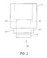
- FIG. 1schematically illustrates an optical assembly in accordance with certain embodiments described herein.
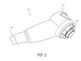
- FIG. 2schematically illustrates a light delivery apparatus compatible with certain embodiments described herein.
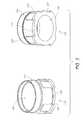
- FIG. 3schematically illustrates two perspective views of a thermal conduit compatible with certain embodiments described herein.
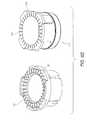
- FIGS. 4A and 4Bschematically illustrate example heat dissipating surfaces and example thermal conduits in accordance with certain embodiments described herein.
- FIGS. 5A and 5Bschematically illustrate two perspective views of an example optical assembly comprising a coupling portion in accordance with certain embodiments described herein.
- FIG. 5Cschematically illustrates a perspective view of an example “bayonet ring” portion of the light delivery apparatus compatible with certain embodiments described herein.
- FIGS. 6A-6Fschematically illustrate a series of configurations of the optical assembly and light delivery apparatus in accordance with certain embodiments described herein.
- FIG. 7schematically illustrates an example coupling portion comprising one or more indicators with two alternative appearances in accordance with certain embodiments described herein.
- FIG. 8schematically illustrates an exploded perspective view of an example mechanism in accordance with certain embodiments described herein.
- FIG. 9schematically illustrates two perspective views of an example first element in accordance with certain embodiments described herein.
- FIG. 10schematically illustrates two perspective views of an example second element in accordance with certain embodiments described herein.
- FIG. 11schematically illustrates two perspective views of an example third element in accordance with certain embodiments described herein.
- FIG. 12schematically illustrates an example spring element in accordance with certain embodiments described herein.
- FIG. 13schematically illustrates an example plate element in accordance with certain embodiments described herein.
- FIG. 14Aschematically illustrates two perspective views of an example optical assembly in accordance with certain embodiments described herein with the first element partially cut-away.
- FIG. 14Bschematically illustrates two perspective views of the example optical assembly of FIG. 14A with the first element totally removed.
- FIG. 15is a flow diagram of an example method of releasably mounting an optical assembly to a light delivery apparatus in accordance with certain embodiments described herein.
- the optical assembly of certain embodiments described hereinis advantageously releasably mounted to the light delivery apparatus, thereby allowing the optical assembly to be (i) sterilized or otherwise cleaned separate from the light delivery apparatus, or (ii) disposed of after a single use.
- the optical assemblycan be configured to be attached or affixed to the light delivery apparatus, and after the patient's body has been irradiated, the optical assembly can be detached or removed from the light delivery apparatus.
- the optical assembly of certain embodimentsafter being removed, the optical assembly of certain embodiments is configured to not be re-attachable to the light delivery apparatus.
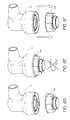
- FIG. 1schematically illustrates an optical assembly 100 in accordance with certain embodiments described herein.
- the optical assembly 100is releasably mountable to a light delivery apparatus 10 comprising at least one heat dissipating surface 20 .
- the optical assembly 100comprises an output optical element 110 comprising a thermally conductive and optically transmissive material.
- the optical assembly 100further comprises a thermal conduit 120 in thermal communication with the output optical element 110 and comprising at least one surface 122 configured to be in thermal communication with the at least one heat dissipating surface 20 .
- the optical assembly 100further comprises a coupling portion 130 configured to be placed in at least two states.
- the coupling portion 130is attached to the light delivery apparatus 10 such that the at least one surface 122 of the thermal conduit 120 is in thermal communication with the at least one heat dissipating surface 20 of the light delivery apparatus 10 .
- the coupling portion 130is detached from the light delivery apparatus 10 after having been attached to the light delivery apparatus 10 in the first state and in which the coupling portion 130 is configured to prevent re-attachment of the coupling portion 130 to the light delivery apparatus 10 .
- the light delivery apparatus 10is configured to deliver light to a portion of a patient's body.
- the light delivery apparatus 10is configured for treatment of a patient's brain by irradiating a portion of the patient's scalp with a predetermined wavelength and power density of laser light (e.g., as described in U.S. Pat. No. 7,303,578, which is incorporated in its entirety by reference herein).
- the light delivery apparatus 10comprises a housing 12 which is optically coupled to a light source (e.g., a laser) via an optical conduit 14 .
- a light sourcee.g., a laser
- the housing 12is sized to be hand-held during operation.
- the at least one heat dissipating surface 20 of the light delivery apparatus 10in certain embodiments comprises a thermally conductive material (e.g., copper, aluminum, or other metal) which is in thermal communication with a cooling system (not shown).
- the cooling systemin accordance with certain embodiments described herein utilizes one or more cooling mechanisms, including, but not limited to, a reservoir containing a cooling material (e.g., a cryogen), a conduit through which a cooling liquid (e.g., water) flows, a thermoelectric device, and a refrigerator.
- a cooling materiale.g., a cryogen
- a cooling liquide.g., water
- the output optical element 110comprises a material which is substantially thermally conductive and which is substantially optically transmissive to light emitted by the light delivery apparatus 10 (e.g., light in the wavelength range of 600 nanometers to 2000 nanometers, light in an infrared wavelength range).
- Example materials for the output optical element 110include but are not limited to, sapphire, diamond, and calcium fluoride.
- the output optical element 110comprises a lens having at least one curved surface (e.g., convex or concave) through which the light from the light delivery apparatus 10 is transmitted.
- the output optical element 110comprises a window having two substantially planar surfaces.
- the output optical element 110comprises a diffuser which diffuses the light transmitted through the output optical element 110 .
- the thermal conduit 120comprises a thermally conductive material (e.g., copper, aluminum, or other metal).
- the at least one surface 122 of the thermal conduit 120comprises the thermally conductive material.
- the thermal conduit 120comprises at least one of aluminum, nickel, and zinc.
- the at least one surface 122is anodized, while in certain other embodiments, the thermal conduit 120 comprises a nickel plating.
- the thermal conduit 120is constructed of a single unitary piece, while in certain other embodiments, the thermal conduit 120 comprises a plurality of portions which are coupled or affixed together.
- the thermal conduit 120is bonded to the output optical element 110 (e.g., by a thermally conductive material, by press fitting, by swaging, by metal injection, or by a collet spring).
- the thermal conduit 120 of certain embodimentsis in thermal communication with the output optical element 110 and has sufficient thermal conductivity such that the output optical element 110 is cooled by the at least one heat dissipating surface 20 of the light delivery apparatus 10 when the optical assembly 100 is mounted to the light delivery apparatus 10 .
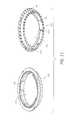
- FIG. 3schematically illustrates two perspective views of a thermal conduit 120 compatible with certain embodiments described herein.
- the thermal conduit 120 schematically illustrated by FIG. 3comprises an elongate tube 123 having a first end portion 124 and a second end portion 125 .
- the first end portion 124is in thermal communication with the output optical element 120 and the second end portion 125 comprises the at least one surface 122 configured to be in thermal communication with the at least one heat dissipating surface 20 of the light delivery apparatus 10 .
- the first end portion 124 of the thermal conduit 120 of certain embodimentscomprises a hole 126 through which light from the light delivery apparatus 10 propagates to the output optical element 110 during operation.
- the output optical element 110fits at least partially within the hole 126 and is in thermal communication with an inner surface of the first end portion 124 .
- the first end portion 124comprises an outer surface which is in thermal communication with a portion of the output optical element 110 .
- FIGS. 4A and 4Bschematically illustrate example heat dissipating surfaces 20 and example thermal conduits 120 in accordance with certain embodiments described herein.
- the at least one surface 122 of the second end portion 125comprises one or more portions 127 configured to fit with one or more portions 22 of the at least one heat dissipating surface 20 .
- the one or more portions 127 and the one or more portions 22provide registration of the second end portion 125 with the at least one heat dissipating surface 20 .
- FIG. 4A and 4Bschematically illustrate example heat dissipating surfaces 20 and example thermal conduits 120 in accordance with certain embodiments described herein.
- the at least one surface 122 of the second end portion 125comprises one or more portions 127 configured to fit with one or more portions 22 of the at least one heat dissipating surface 20 .
- the one or more portions 127 and the one or more portions 22provide registration of the second end portion 125 with the at least one heat dissipating surface 20 .
- the one or more portions 127 of the second end portion 125comprise one or more protrusions and the one or more portions 22 of the at least one heat dissipating surface 20 comprise one or more recesses.
- the protrusionscan comprise substantially planar portions (e.g., four tabs) of the second end portion 125 and the recesses can comprise regions (e.g., four) between projections of the at least one heat dissipating surface 20 which extend substantially perpendicularly to the protrusions, as schematically illustrated by FIG. 4A .
- the one or more portions 127 of the second end portion 125comprise one or more recesses and the one or more portions 22 of the at least one heat dissipating surface 20 comprise one or more protrusions.
- the protrusionscan comprise a plurality of fins or pins (e.g., more than ten) and the recesses can comprise slots or holes (e.g., more than ten) into which the fins at least partially fit.
- the fit of the protrusions into the recessesis sufficiently loose so that their relative alignment and the application force used to place the second end portion 125 of the thermal conduit 120 in thermal communication with the at least one heat dissipating surface 20 do not unduly hinder mounting the optical assembly 100 to the light delivery apparatus 10 .
- the one or more portions 127 of the second end portion 125comprise one or more protrusions and recesses and the one or more portions 22 of the at least one heat dissipating surface 20 comprise one or more recesses and protrusions which are configured to fit with one or more portions 127 of the second end portion 125 .
- Various other configurations of the heat dissipating surface 20 and the at least one surface 122 of the thermal conduit 120are also compatible with certain embodiments described herein.
- the numbers, shapes, sizes, and configurations of the one or more portions 127can be selected to exhibit an appearance which is indicative of the manufacturer or source of the optical assembly 100 .
- Certain embodimentsutilize a heat dissipating surface 20 and a thermal conduit 120 which advantageously control the allowable relative motion of the at least one surface 122 of the thermal conduit 120 and the at least one heat dissipating surface 20 of the light delivery apparatus 10 during the process of connecting and disconnecting the optical assembly 100 and the light delivery apparatus 10 .
- the at least one surface 122can be restricted from rotating relative to the at least one heat dissipating surface 20 during the mounting or dismounting process so as to reduce any rubbing or friction between these two surfaces.
- Certain such embodiments in which the at least one surface 122 of the thermal conduit 120 does not rotate relative to the at least one heat dissipating surface 20advantageously avoid wear of the at least one heat dissipating surface 20 due to repeated mounting/dismounting of optical assemblies 100 .
- Rotation of the coupling portion 130 in certain embodimentsengages the coupling portion 130 to the light delivery apparatus 10 without the output optical element 110 rotating relative to the light delivery apparatus 10 .
- At least one of the heat dissipating surface 20 of the light delivery apparatus 10 and the at least one surface 122 of the thermal conduit 120comprises a material selected to improve the thermal conductivity between the at least one heat dissipating surface 20 and the at least one surface 122 .
- the at least one surface 122can comprise a relatively soft material (e.g., indium plating) and the at least one heat dissipating surface 20 can comprise a relatively hard material (e.g., silicon carbide or diamond grit).
- the hard materialdeforms the soft material at one or more contact points between the two surfaces, thereby making good thermal contact between the two surfaces.
- an intervening materialis placed between the at least one heat dissipating surface 20 and the at least one surface 122 .
- the intervening materialadvantageously improves the thermal conductivity between the at least one heat dissipating surface 20 and the at least one surface 122 .
- the intervening materialcan comprise a metal which is deformed by pressure between the at least one heat dissipating surface 20 and the at least one surface 122 or a thermally conductive grease.
- the intervening materialis part of an adapter configured to be placed at least partially between the at least one heat dissipating surface 20 and the at least one surface 122 .
- the adaptercomprises one or more first portions (e.g., protrusions, recesses, or both) configured to fit with one or more portions (e.g., recesses, protrusions, or both) of the light delivery apparatus 10 , and one or more second portions configured to fit with one or more portions of the thermal conduit 120 .
- the adapter of certain embodimentscan provide thermal conductivity between the at least one heat dissipating surface 20 and the thermal conduit 120 .
- the adapter of certain embodimentsis configured to fit with the one or more portions 127 of the second end portion 125 and with the one or more portions 22 of the at least one heat dissipating surface 20 .
- the adapteris configured to fit with the one or more portions 127 and with the one or more portions 22 although the one or more portions 127 do not fit with the one or more portions 22 .
- the adapter of certain embodimentsadvantageously provides a sufficient fit with the one or more portions 127 and with the one or more portions 22 so that an optical assembly 100 that would otherwise not mount to the light delivery apparatus 10 can be mounted to the light delivery apparatus 10 .
- the coupling portion 130 of certain embodimentsis coupled to the thermal conduit 120 , and provides a mechanism for attaching the thermal conduit 120 to the light delivery apparatus 10 .
- the coupling portion 130comprises one or more protrusions 132 configured to fit with one or more recesses of the light delivery apparatus 10 .
- the coupling portion 130comprises one or more recesses configured to fit with one or more protrusions of the light delivery apparatus 10 .
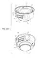
- FIGS. 5A and 5Bschematically illustrate two perspective views of an example optical assembly 100 comprising a coupling portion 130 in accordance with certain embodiments described herein.
- FIG. 5Cschematically illustrates a perspective view of an example “bayonet ring” portion 30 of the light delivery apparatus 10 compatible with certain embodiments described herein.
- the coupling portion 130comprises one or more protrusions 132 , as schematically illustrated by FIG. 5A , which are configured to fit with recesses 32 of a portion 30 of the light delivery apparatus 10 , as schematically illustrated by FIG. 5C .
- connection between the coupling portion 130 and the light delivery apparatus 10is spring loaded (e.g., upon rotation of the optical assembly 100 relative to the light delivery apparatus 10 such that the protrusions 132 move along the recesses 32 ), such that upon connecting the optical assembly 100 to the light delivery apparatus 10 , a force is generated which provides a consequent contact pressure between the at least one surface 125 of the thermal conduit 122 and the at least one heat dissipating surface 20 of the light delivery apparatus 10 .
- FIGS. 6A-6Fschematically illustrate a series of configurations of the optical assembly 100 and light delivery apparatus 10 in accordance with certain embodiments described herein.
- FIGS. 6A-6Cschematically illustrate an example process of placing the coupling portion 130 in the first state in which the coupling portion 130 is attached to the light delivery apparatus 10 such that the at least one surface 122 of the thermal conduit 120 is in thermal communication with the at least one heat dissipating surface 20 of the light delivery apparatus 10 .
- the coupling portion 130is in a third state in which the coupling portion 130 is unattached to the light delivery apparatus 10 and is configured to be attached to the light delivery apparatus 10 prior to being in the first state.
- FIG. 6Athe configuration shown in FIG.
- the coupling portion 130is placed in proximity to the light delivery apparatus 10 , such that one or more portions of the coupling portion 130 at least partially engage with one or more portions of the light delivery apparatus 10 .
- the optical assembly 100is placed in contact with the light delivery apparatus 10 and the coupling portion 130 is rotated relative to the light delivery apparatus 10 .
- the optical assembly 100is attached to the light delivery apparatus 10 with the coupling portion 130 in the first state.
- the thermal conduit 120is electrically coupled to an electrical ground when the coupling portion 130 is in the first state.
- FIGS. 6D-6Fschematically illustrate an example process of attempting to re-attach the optical assembly 100 to the light delivery apparatus 10 while the coupling portion 130 is in the second state.
- the coupling portion 130is in the second state in which the coupling portion 130 is unattached to the light delivery apparatus 10 and is configured to prevent re-attachment to the light delivery apparatus 10 after being in the first state.
- the configuration shown in FIG. 6Dthe coupling portion 130 is in the second state in which the coupling portion 130 is unattached to the light delivery apparatus 10 and is configured to prevent re-attachment to the light delivery apparatus 10 after being in the first state.
- the coupling portion 130is placed in proximity to the light delivery apparatus 10 (e.g., the optical assembly 100 is placed in contact with the light delivery apparatus 10 ), but portions of the optical assembly 100 cannot engage portions of the light delivery apparatus 10 (e.g., even if the coupling portion 130 is attempted to be rotated relative to the light delivery apparatus 10 , as schematically illustrated by FIG. 6E ).
- the optical assembly 100is not attached to the light delivery apparatus 10 and falls away from the light delivery apparatus 10 .
- FIG. 7schematically illustrates an example coupling portion 130 comprising one or more indicators 134 with two alternative appearances in accordance with certain embodiments described herein.
- the indicator 134provides a visual indication of the current state in which the coupling portion 130 is in. For example, on the left side of FIG. 7 , the indicator 134 displays a first color (e.g., green) indicative of the coupling portion 130 being in the first state. On the right side of FIG. 7 , the indicator 134 displays a second color (e.g., red) indicative of the coupling portion 130 being in the second state.
- a first colore.g., green
- the indicator 134displays a second color (e.g., red) indicative of the coupling portion 130 being in the second state.
- Certain other embodimentsutilize an indicator 134 located at other positions of the coupling portion 130 .
- Certain other embodimentsutilize one or more indicators 134 with other indicia of the state of the coupling portion 130 , including but not limited to, alphanumeric characters
- the coupling portion 130comprises a mechanism 140 which allows rotation of the coupling portion 130 in a first direction to place the coupling portion 130 in the first state and which allows rotation of the coupling portion 130 in a second direction opposite to the first direction to remove the coupling assembly 130 from the first state.
- the mechanism 140 of certain such embodimentsis configured to inhibit rotation of the coupling portion 130 in the first direction upon the coupling portion 130 being removed from the first state.
- FIG. 8schematically illustrates an exploded perspective view of an example mechanism 140 in accordance with certain embodiments described herein.
- the mechanism 140comprises a first element 150 , a second element 160 , and a third element 170 .
- the second element 160is between the first element 150 and the third element 170 .
- FIG. 9schematically illustrates two perspective views of an example first element 150 in accordance with certain embodiments described herein.
- the first element 150comprises a plastic resin (e.g., thermoplastic polymer, acrylonitrile butadiene styrene or ABS, polyvinyl chloride or PVC, acetal-based), although other materials are also compatible with certain embodiments described herein.
- the first element 150is a portion of the coupling portion 130 , as schematically illustrated by FIG. 9 .
- the first element 150comprises a first plurality of protrusions 151 (e.g., ratchet teeth) positioned along a first circle 152 and a second plurality of protrusions 153 (e.g., ratchet teeth) positioned along a second circle 154 substantially concentric with the first circle 152 .
- the first element 150 of certain embodimentshas a generally cylindrical shape.
- the protrusions 151 and the protrusions 153are on an inner surface of the first element 150 .
- the protrusions 151extend further from the inner surface than do the protrusions 153 .
- the first plurality of protrusions 151have a smaller number of protrusions (e.g., four) than does the second plurality of protrusions 153 (e.g., between 20 and 40).
- the first element 150 of certain embodimentsfurther comprises a hole 155 generally concentric with the first circle 152 and the second circle 154 through which the thermal conduit 120 is configured to extend.
- the first element 150 of certain embodimentsfurther comprises an outer housing 156 configured to be gripped by a user to attach/detach the coupling portion 130 to/from the light delivery apparatus 10 .
- the first element 150further comprises the protrusions 132 (e.g., pins extending radially inward towards a center of the first element 150 ) of the coupling portion 130 which fit in respective recesses of the light delivery apparatus 10 .
- the first element 150is configured to be removably affixed to the light delivery apparatus 10 thereby allowing the coupling portion 130 to be attached and detached from the light delivery apparatus 10 .
- the first element 150further comprises one or more indicator holes 157 through which a user can see the one or more indicators 134 of the coupling portion 130 .
- FIG. 10schematically illustrates two perspective views of an example second element 160 in accordance with certain embodiments described herein.
- the second element 160comprises a plastic resin (e.g., thermoplastic polymer, acrylonitrile butadiene styrene or ABS, polyvinyl chloride or PVC, acetal-based), although other materials are also compatible with certain embodiments described herein.
- the second element 160comprises a first side 161 and a second side 162 opposite to the first side 161 .
- the second element 160further comprises a third plurality of protrusions 163 (e.g., ratchet teeth) on the first side 161 and configured to mate with the first plurality of protrusions 151 .
- a plastic resine.g., thermoplastic polymer, acrylonitrile butadiene styrene or ABS, polyvinyl chloride or PVC, acetal-based
- the second element 160comprises a first side 161 and a second side 162 opposite
- the second element 160further comprises a fourth plurality of protrusions 164 (e.g., ratchet teeth) on the second side 162 .
- the second element 160is generally annular with a hole 165 through which the thermal conduit 120 is configured to extend.
- the third plurality of protrusions 163have a smaller number of protrusions (e.g., four) than does the fourth plurality of protrusions 164 (e.g., between 20 and 40).
- the first side 161further comprises the one or more indicators 134 of the coupling portion 130 .
- the third element 170further comprises a sixth plurality of protrusions 172 (e.g., ratchet teeth) configured to mate with the fourth plurality of protrusions 164 .
- the fifth plurality of protrusions 171 and the sixth plurality of protrusions 172 of certain embodimentsare on the same side 173 of the third element 170 but with the protrusions 171 extending farther from the side 173 than do the protrusions 172 , as schematically illustrated by FIG. 11 .
- the fifth plurality of protrusions 171extend through the hole 165 of the second element 160 to engage the second plurality of protrusions 153 of the first element 150 .
- the third element 170is generally annular with a hole 174 through which the thermal conduit 120 is configured to extend. In certain embodiments, the third element 170 further comprises one or more portions 175 which engage corresponding portions 128 of the thermal conduit 120 , such that the third element 170 is keyed to the thermal conduit 120 .
- the mechanism 140further comprises a spring element 180 and a plate element 190 , as schematically illustrated in FIG. 8 .
- FIG. 12schematically illustrates an example spring element 180 in accordance with certain embodiments described herein.
- the spring element 180comprises a metal (e.g., stainless steel), although other materials are also compatible with certain embodiments described herein.
- the spring element 180 of certain embodimentsis generally annular with a hole 181 through which the thermal conduit 120 is configured to extend.
- the spring element 180 of certain embodimentshas a portion 182 configured to press against the third element 170 (e.g., against a side opposite to the side 173 ).
- the spring element 180comprises one or more leaf springs 183 which extend away from the portion 182 , as schematically illustrated by FIG. 12 . As described more fully below, the spring element 180 is placed between the third element 170 and the plate element 190 , such that the leaf springs 183 are compressed thereby providing a force on the third element 170 towards the second element 160 and the first element 150 .
- FIG. 13schematically illustrates an example plate element 190 in accordance with certain embodiments described herein.
- the plate element 190comprises a plastic resin (e.g., thermoplastic polymer, acrylonitrile butadiene styrene or ABS, polyvinyl chloride or PVC, acetal-based), although other materials are also compatible with certain embodiments described herein.
- the plate element 190 of certain embodimentsis generally annular with a hole 191 through which the thermal conduit 120 is configured to extend.
- the plate element 190comprises one or more portions 192 configured to engage one or more portions of the first element 150 .
- the plate element 190further comprises one or more portions 193 configured to engage one or more portions (e.g., portions 127 ) of the thermal conduit 120 .
- FIG. 14Aschematically illustrates two perspective views of an example optical assembly 100 in accordance with certain embodiments described herein with the first element 150 partially cut-away.
- FIG. 14Bschematically illustrates two perspective views of the example optical assembly 100 of FIG. 14A with the first element 150 totally removed.
- the optical assembly 100is placed in proximity to the light delivery apparatus 10 .
- the optical assembly 100is at least partially inserted into the light delivery apparatus 10 such that the portions 127 of the thermal conduit 120 mate with the portions 22 of the at least one heat dissipating surface 20 of the light delivery apparatus 10 .
- the coupling portion 130is rotated (e.g., clockwise) relative to the light delivery apparatus 10 , while the thermal conduit 120 does not rotate relative to the at least one heat dissipating surface 20 .
- This rotationpulls the coupling portion 130 and the portion of the light delivery apparatus 10 towards one another, and also pulls the thermal conduit 120 and the at least one heat dissipating surface 130 towards one another, and creates a thermal contact force pressing the thermal conduit 120 and at least one heat dissipating surface 130 together.
- the third element 170is disengaged from the first element 150 .
- the second element 160rotates with the first element 150 (which is part of the coupling portion 130 ), driven by the first plurality of protrusions 151 of the first element 150 .
- This actioncauses the third element 170 (which is keyed to the thermal conduit 120 ) to ratchet up and down as the fourth plurality of protrusions 164 pass beneath the sixth plurality of protrusions 172 .
- Rotation of the coupling portion 130stops in certain embodiments when the protrusions 132 of the coupling portion 130 reach the ends of the recesses 32 of the portion 30 of the light delivery apparatus 10 .
- the optical assembly 100is mounted to the light delivery apparatus 10 and is positioned for operation of the light delivery apparatus 10 .
- one or more portionse.g., green portions
- one or more portionse.g., green portions
- the first side 161 of the second element 160align with the one or more indicator windows 157 of the first element 150 to indicate that the coupling portion 130 is in the first state.
- the coupling portion 130is rotated in the opposite direction (e.g., counterclockwise) relative to the light delivery apparatus 10 .
- the second element 160is prevented from rotating by the interaction of the fourth plurality of protrusions 164 with the sixth plurality of protrusions 172 .
- the coupling portion 130 of certain embodimentshas been rotated by a predetermined angle (e.g., 10 degrees)
- the second element 160disengages (e.g., moves off) from the first plurality of protrusions 151 of the first element 150 .
- Counter-clockwise rotation of the coupling portion 130can continue in certain embodiments until the protrusions 132 reach the end of the recesses 32 of the portion 30 of the light delivery apparatus 10 , upon which the coupling portion 130 can be pulled away from the light delivery apparatus 10 .
- one or more portionse.g., red portions
- one or more portionse.g., red portions
- the first side 161 of the second element 160align with the one or more indicator windows 157 of the first element 150 to indicate that the coupling portion 130 is in the second state.
- FIG. 15is a flow diagram of an example method 200 of releasably mounting an optical assembly 100 to a light delivery apparatus 10 in accordance with certain embodiments described herein.
- the method 200comprises providing the optical assembly 100 .
- the optical assembly 100is adapted to be in at least two states comprising a first state and a second state. In the first state, the optical assembly 100 is attached to the light delivery apparatus 10 . In the second state, the optical assembly 100 is detached from the light delivery apparatus 10 after having been attached to the light delivery apparatus 10 in the first state. Also, in the second state, the optical assembly 100 is configured to prevent re-attachment of the optical assembly 100 to the light delivery apparatus 10 .
- the method 200further comprises attaching the optical assembly 100 to the light delivery apparatus 10 .
- the method 200further comprises detaching the optical assembly 100 from the light delivery apparatus 10 .
- the adapterwould be configured to mate with the optical assembly 100 when the optical assembly 100 is in the first state, when the optical assembly 100 is in the second state, or when the optical assembly 100 is in either the first state or the second state. In certain other embodiments, the adapter would be configured so that the optical assembly 100 is not placed in the second state when the optical assembly 100 is detached from the adapter. Thus, detaching the optical assembly 100 from the light delivery apparatus 10 in certain such embodiments comprises avoiding placing the optical assembly 100 in the second state.
Landscapes
- Health & Medical Sciences (AREA)
- Engineering & Computer Science (AREA)
- Biomedical Technology (AREA)
- Pathology (AREA)
- Nuclear Medicine, Radiotherapy & Molecular Imaging (AREA)
- Radiology & Medical Imaging (AREA)
- Life Sciences & Earth Sciences (AREA)
- Animal Behavior & Ethology (AREA)
- General Health & Medical Sciences (AREA)
- Public Health (AREA)
- Veterinary Medicine (AREA)
- Optical Couplings Of Light Guides (AREA)
Abstract
Description
Claims (26)
Priority Applications (5)
| Application Number | Priority Date | Filing Date | Title |
|---|---|---|---|
| US12/233,498US7848035B2 (en) | 2008-09-18 | 2008-09-18 | Single-use lens assembly |
| EP12168348AEP2522393A1 (en) | 2008-09-18 | 2009-09-18 | Single-use lens assembly |
| EP09170679AEP2165736A1 (en) | 2008-09-18 | 2009-09-18 | Single-use lens assembly |
| US12/938,146US8149526B2 (en) | 2008-09-18 | 2010-11-02 | Single use lens assembly |
| US13/342,428US10071259B2 (en) | 2008-09-18 | 2012-01-03 | Optical assembly |
Applications Claiming Priority (1)
| Application Number | Priority Date | Filing Date | Title |
|---|---|---|---|
| US12/233,498US7848035B2 (en) | 2008-09-18 | 2008-09-18 | Single-use lens assembly |
Related Child Applications (1)
| Application Number | Title | Priority Date | Filing Date |
|---|---|---|---|
| US12/938,146ContinuationUS8149526B2 (en) | 2008-09-18 | 2010-11-02 | Single use lens assembly |
Publications (2)
| Publication Number | Publication Date |
|---|---|
| US20100067128A1 US20100067128A1 (en) | 2010-03-18 |
| US7848035B2true US7848035B2 (en) | 2010-12-07 |
Family
ID=41426148
Family Applications (3)
| Application Number | Title | Priority Date | Filing Date |
|---|---|---|---|
| US12/233,498Active - Reinstated2029-02-18US7848035B2 (en) | 2008-09-18 | 2008-09-18 | Single-use lens assembly |
| US12/938,146Active2028-09-20US8149526B2 (en) | 2008-09-18 | 2010-11-02 | Single use lens assembly |
| US13/342,428ActiveUS10071259B2 (en) | 2008-09-18 | 2012-01-03 | Optical assembly |
Family Applications After (2)
| Application Number | Title | Priority Date | Filing Date |
|---|---|---|---|
| US12/938,146Active2028-09-20US8149526B2 (en) | 2008-09-18 | 2010-11-02 | Single use lens assembly |
| US13/342,428ActiveUS10071259B2 (en) | 2008-09-18 | 2012-01-03 | Optical assembly |
Country Status (2)
| Country | Link |
|---|---|
| US (3) | US7848035B2 (en) |
| EP (2) | EP2165736A1 (en) |
Cited By (6)
| Publication number | Priority date | Publication date | Assignee | Title |
|---|---|---|---|---|
| US8025687B2 (en) | 2003-01-24 | 2011-09-27 | Photothera, Inc. | Low level light therapy for enhancement of neurologic function |
| US8149526B2 (en) | 2008-09-18 | 2012-04-03 | Photothera, Inc. | Single use lens assembly |
| US8308784B2 (en) | 2006-08-24 | 2012-11-13 | Jackson Streeter | Low level light therapy for enhancement of neurologic function of a patient affected by Parkinson's disease |
| US10188872B2 (en) | 2006-01-30 | 2019-01-29 | Pthera LLC | Light-emitting device and method for providing phototherapy to the brain |
| US10357662B2 (en) | 2009-02-19 | 2019-07-23 | Pthera LLC | Apparatus and method for irradiating a surface with light |
| US11273319B2 (en) | 2008-03-18 | 2022-03-15 | Pthera LLC | Method and apparatus for irradiating a surface with pulsed light |
Families Citing this family (7)
| Publication number | Priority date | Publication date | Assignee | Title |
|---|---|---|---|---|
| US7303578B2 (en) | 2001-11-01 | 2007-12-04 | Photothera, Inc. | Device and method for providing phototherapy to the brain |
| US20070179570A1 (en)* | 2006-01-30 | 2007-08-02 | Luis De Taboada | Wearable device and method for providing phototherapy to the brain |
| US10589120B1 (en) | 2012-12-31 | 2020-03-17 | Gary John Bellinger | High-intensity laser therapy method and apparatus |
| JP2022552020A (en) | 2019-10-15 | 2022-12-14 | ジェリカライト エルエルシー | head wearable phototherapy device |
| USD949355S1 (en) | 2019-10-15 | 2022-04-19 | JelikaLite, LLC | Head wearable light therapy device |
| MX2023011754A (en) | 2021-04-08 | 2023-11-09 | Niraxx Inc | GARMENT FOR PHOTOBIOMODULATION THERAPY, METHODS AND USES. |
| US11944840B2 (en) | 2021-04-08 | 2024-04-02 | Niraxx Light Therapeutics, Inc. | Photobiomodulation therapy garment, methods and uses |
Citations (152)
| Publication number | Priority date | Publication date | Assignee | Title |
|---|---|---|---|---|
| US3735755A (en) | 1971-06-28 | 1973-05-29 | Interscience Research Inst | Noninvasive surgery method and apparatus |
| US3810367A (en) | 1970-07-16 | 1974-05-14 | W Peterson | Container for cooling, storage, and shipping of human organ for transplant |
| US4076393A (en)* | 1975-12-15 | 1978-02-28 | The United States Of America As Represented By The Secretary Of The Navy | Thermal stress-relieving coupling member and support |
| US4315514A (en) | 1980-05-08 | 1982-02-16 | William Drewes | Method and apparatus for selective cell destruction |
| US4343301A (en) | 1979-10-04 | 1982-08-10 | Robert Indech | Subcutaneous neural stimulation or local tissue destruction |
| DE3200584A1 (en) | 1982-01-12 | 1983-07-21 | geb. Budwig Johanna Dr. 7290 Freudenstadt Budwig | Method for controlling the energy level, especially of the pi electrons, in water by means of a red-light laser in such a way that the water treated in this way can be used for preserving transplants |
| US4630273A (en) | 1981-09-11 | 1986-12-16 | Nippon Infrared Industries, Co., Ltd. | Laser device |
| US4633872A (en) | 1983-11-08 | 1987-01-06 | Hgm, Incorporated | Laser optical delivery apparatus |
| US4669466A (en) | 1985-01-16 | 1987-06-02 | Lri L.P. | Method and apparatus for analysis and correction of abnormal refractive errors of the eye |
| US4671285A (en) | 1984-04-20 | 1987-06-09 | Judith Walker | Treatment of human neurological problems by laser photo simulation |
| US4798215A (en) | 1984-03-15 | 1989-01-17 | Bsd Medical Corporation | Hyperthermia apparatus |
| US4846196A (en) | 1986-01-29 | 1989-07-11 | Wiksell Hans O T | Method and device for the hyperthermic treatment of tumors |
| US4850351A (en) | 1985-05-22 | 1989-07-25 | C. R. Bard, Inc. | Wire guided laser catheter |
| EP0130950B1 (en) | 1983-07-04 | 1990-04-11 | Adriano Tessiore | Radiating electromechanical apparatus for treating scalp against baldness |
| US4930504A (en) | 1987-11-13 | 1990-06-05 | Diamantopoulos Costas A | Device for biostimulation of tissue and method for treatment of tissue |
| US4951482A (en) | 1988-12-21 | 1990-08-28 | Gilbert Gary L | Hypothermic organ transport apparatus |
| US4951653A (en) | 1988-03-02 | 1990-08-28 | Laboratory Equipment, Corp. | Ultrasound brain lesioning system |
| US4966144A (en) | 1987-06-09 | 1990-10-30 | Simeone Rochkind | Method for inducing regeneration of injured nerve fibers |
| US5029581A (en) | 1986-11-19 | 1991-07-09 | Fuji Electric Co., Ltd. | Laser therapeutic apparatus |
| US5037374A (en) | 1989-11-29 | 1991-08-06 | Carol Mark P | Stereotactic-guided radiation therapy system with variable-length compensating collimator |
| US5054470A (en) | 1988-03-02 | 1991-10-08 | Laboratory Equipment, Corp. | Ultrasonic treatment transducer with pressurized acoustic coupling |
| DE4108328A1 (en) | 1991-03-14 | 1992-09-17 | Durango Holding Gmbh | Therapy treatment radiation appts. - has control circuit determining duration of IR, visible or UV radiation from matrix of elements e.g. LEDs |
| US5150704A (en) | 1986-06-23 | 1992-09-29 | Fuji Electric Co., Ltd. | Laser therapeutic apparatus |
| DE4213053A1 (en) | 1992-04-21 | 1993-10-28 | Matthias Dr Ing Herrig | Laser radiation application device for brain tumour therapy - has radiation element at distal end of flexible light conductor enclosed by cooled hermetically sealed outer sheath |
| US5259380A (en) | 1987-11-04 | 1993-11-09 | Amcor Electronics, Ltd. | Light therapy system |
| US5267294A (en) | 1992-04-22 | 1993-11-30 | Hitachi Medical Corporation | Radiotherapy apparatus |
| US5282797A (en) | 1989-05-30 | 1994-02-01 | Cyrus Chess | Method for treating cutaneous vascular lesions |
| US5358503A (en) | 1994-01-25 | 1994-10-25 | Bertwell Dale E | Photo-thermal therapeutic device and method |
| US5368555A (en) | 1992-12-29 | 1994-11-29 | Hepatix, Inc. | Organ support system |
| US5401270A (en) | 1990-12-19 | 1995-03-28 | Carl-Zeiss-Stiftung | Applicator device for laser radiation |
| US5441495A (en) | 1989-08-17 | 1995-08-15 | Life Resonances, Inc. | Electromagnetic treatment therapy for stroke victim |
| US5445146A (en) | 1995-03-31 | 1995-08-29 | Bellinger; Gary J. | Biological tissue stimulation by low level optical energy |
| US5445608A (en) | 1993-08-16 | 1995-08-29 | James C. Chen | Method and apparatus for providing light-activated therapy |
| US5464436A (en) | 1994-04-28 | 1995-11-07 | Lasermedics, Inc. | Method of performing laser therapy |
| DE29515096U1 (en) | 1995-05-16 | 1995-11-30 | Wilden Lutz Dr Med | Device for stimulating the central nervous system |
| US5474528A (en) | 1994-03-21 | 1995-12-12 | Dusa Pharmaceuticals, Inc. | Combination controller and patch for the photodynamic therapy of dermal lesion |
| US5501655A (en) | 1992-03-31 | 1996-03-26 | Massachusetts Institute Of Technology | Apparatus and method for acoustic heat generation and hyperthermia |
| US5511563A (en) | 1991-06-21 | 1996-04-30 | Diamond; Donald A. | Apparatus and method for treating rheumatoid and psoriatic arthritis |
| US5540737A (en) | 1991-06-26 | 1996-07-30 | Massachusetts Institute Of Technology | Minimally invasive monopole phased array hyperthermia applicators and method for treating breast carcinomas |
| US5580550A (en) | 1992-04-22 | 1996-12-03 | Chesebrough-Pond's Usa Co., Division Of Conopco, Inc. | Cosmetic composition comprising particles of polyisobutylene resin and process for the preparation of same |
| US5580555A (en) | 1990-04-23 | 1996-12-03 | Yeda Research And Development Co. Ltd. | Regeneration of injured central nervous system axons |
| US5601526A (en) | 1991-12-20 | 1997-02-11 | Technomed Medical Systems | Ultrasound therapy apparatus delivering ultrasound waves having thermal and cavitation effects |
| EP0763371A2 (en) | 1995-09-15 | 1997-03-19 | ESC Medical Systems Ltd. | Method and apparatus for skin rejuvenation and wrinkle smoothing |
| US5616140A (en)* | 1994-03-21 | 1997-04-01 | Prescott; Marvin | Method and apparatus for therapeutic laser treatment |
| US5617258A (en) | 1995-10-25 | 1997-04-01 | Plc Medical Systems, Inc. | Non-reusable lens cell for a surgical laser handpiece |
| US5621091A (en) | 1986-07-25 | 1997-04-15 | The Children's Medical Center Corporation | Probes for and nucleic acid encoding the muscular dystrophy protein, dystrophin |
| US5622168A (en) | 1992-11-18 | 1997-04-22 | John L. Essmyer | Conductive hydrogels and physiological electrodes and electrode assemblies therefrom |
| US5627870A (en) | 1993-06-07 | 1997-05-06 | Atea, Societe Atlantique De Techniques Avancees | Device for treating cerebral lesions by gamma radiation, and corresponding treatment apparatus |
| US5640978A (en) | 1991-11-06 | 1997-06-24 | Diolase Corporation | Method for pain relief using low power laser light |
| US5643334A (en) | 1995-02-07 | 1997-07-01 | Esc Medical Systems Ltd. | Method and apparatus for the diagnostic and composite pulsed heating and photodynamic therapy treatment |
| EP0783904A2 (en) | 1995-12-26 | 1997-07-16 | ESC Medical Systems Ltd. | Method and apparatus for controlling the thermal profile of skin |
| US5728090A (en) | 1995-02-09 | 1998-03-17 | Quantum Devices, Inc. | Apparatus for irradiating living cells |
| US5755752A (en) | 1992-04-24 | 1998-05-26 | Segal; Kim Robin | Diode laser irradiation system for biological tissue stimulation |
| US5762867A (en) | 1994-09-01 | 1998-06-09 | Baxter International Inc. | Apparatus and method for activating photoactive agents |
| US5817008A (en) | 1996-10-31 | 1998-10-06 | Spacelabs Medical, Inc. | Conformal pulse oximetry sensor and monitor |
| US5842477A (en) | 1996-02-21 | 1998-12-01 | Advanced Tissue Sciences, Inc. | Method for repairing cartilage |
| US5843073A (en) | 1985-07-31 | 1998-12-01 | Rare Earth Medical, Inc. | Infrared laser catheter system |
| US5849585A (en) | 1995-05-10 | 1998-12-15 | Genetech, Inc. | Isolating and culturing Schwann cells |
| US5871521A (en) | 1995-08-25 | 1999-02-16 | Matsushita Electric Industrial Co., Ltd. | Laser probe for medical treatment |
| US5879376A (en) | 1995-07-12 | 1999-03-09 | Luxar Corporation | Method and apparatus for dermatology treatment |
| US5902741A (en) | 1986-04-18 | 1999-05-11 | Advanced Tissue Sciences, Inc. | Three-dimensional cartilage cultures |
| US5928945A (en) | 1996-11-20 | 1999-07-27 | Advanced Tissue Sciences, Inc. | Application of shear flow stress to chondrocytes or chondrocyte stem cells to produce cartilage |
| US5928207A (en) | 1997-06-30 | 1999-07-27 | The Regents Of The University Of California | Microneedle with isotropically etched tip, and method of fabricating such a device |
| US5954762A (en) | 1997-09-15 | 1999-09-21 | Di Mino; Alfonso | Computer-controlled servo-mechanism for positioning corona discharge beam applicator |
| US5958761A (en) | 1994-01-12 | 1999-09-28 | Yeda Research And Developement Co. Ltd. | Bioreactor and system for improved productivity of photosynthetic algae |
| US5983141A (en) | 1996-06-27 | 1999-11-09 | Radionics, Inc. | Method and apparatus for altering neural tissue function |
| US5989245A (en) | 1994-03-21 | 1999-11-23 | Prescott; Marvin A. | Method and apparatus for therapeutic laser treatment |
| US6030767A (en) | 1997-01-21 | 2000-02-29 | The American National Red Cross | Intracellular and extracellular decontamination of whole blood and blood components by amphiphilic phenothiazin-5-ium dyes plus light |
| US6042531A (en) | 1995-06-19 | 2000-03-28 | Holcomb; Robert R. | Electromagnetic therapeutic treatment device and methods of using same |
| US6046046A (en) | 1997-09-23 | 2000-04-04 | Hassanein; Waleed H. | Compositions, methods and devices for maintaining an organ |
| US6045575A (en) | 1997-09-10 | 2000-04-04 | Amt, Inc. | Therapeutic method and internally illuminated garment for the management of disorders treatable by phototherapy |
| US6060306A (en) | 1995-06-07 | 2000-05-09 | Advanced Tissue Sciences, Inc. | Apparatus and method for sterilizing, seeding, culturing, storing, shipping and testing replacement cartilage tissue constructs |
| US6063108A (en) | 1997-01-06 | 2000-05-16 | Salansky; Norman | Method and apparatus for localized low energy photon therapy (LEPT) |
| US6100290A (en) | 1992-05-27 | 2000-08-08 | Qlt Inc. | Photodynamic therapy in selective cell inactivation in blood and treating immune dysfunction diseases |
| US6107325A (en) | 1995-01-17 | 2000-08-22 | Qlt Phototherapeutics, Inc. | Green porphyrins as immunomodulators |
| US6107608A (en) | 1997-03-24 | 2000-08-22 | Micron Technology, Inc. | Temperature controlled spin chuck |
| US6112110A (en) | 1997-01-07 | 2000-08-29 | Wilk; Peter J. | Medical treatment system with scanner input |
| US6117128A (en) | 1997-04-30 | 2000-09-12 | Kenton W. Gregory | Energy delivery catheter and method for the use thereof |
| US6129748A (en) | 1996-03-22 | 2000-10-10 | Kamei; Tsutomu | Apparatus for applying pulsed light to the forehead of a user |
| US6143878A (en) | 1994-11-29 | 2000-11-07 | The University Of Queensland | Sox-9 gene and protein and use in the regeneration of bone or cartilage |
| US6146410A (en) | 1995-11-24 | 2000-11-14 | Nagypal; Tibor | Apparatus for the photodynamic treatment of living beings or organs thereof |
| US6149679A (en) | 1997-09-15 | 2000-11-21 | Adm Tronics Ulimited, Inc. | Corona discharge beam treatment of neuro-cerebral disorders |
| US6156028A (en) | 1994-03-21 | 2000-12-05 | Prescott; Marvin A. | Method and apparatus for therapeutic laser treatment of wounds |
| US6162211A (en) | 1996-12-05 | 2000-12-19 | Thermolase Corporation | Skin enhancement using laser light |
| US6179771B1 (en) | 1998-04-21 | 2001-01-30 | Siemens Aktiengesellschaft | Coil arrangement for transcranial magnetic stimulation |
| US6179830B1 (en) | 1996-07-24 | 2001-01-30 | J. Morita Manufacturing Corporation | Laser probe |
| EP1074275A1 (en) | 1998-04-10 | 2001-02-07 | Vladimir Pavlovich Zharov | Photomatrix device |
| US6198958B1 (en) | 1998-06-11 | 2001-03-06 | Beth Israel Deaconess Medical Center, Inc. | Method and apparatus for monitoring a magnetic resonance image during transcranial magnetic stimulation |
| US6210425B1 (en) | 1999-07-08 | 2001-04-03 | Light Sciences Corporation | Combined imaging and PDT delivery system |
| US6210317B1 (en) | 1998-07-13 | 2001-04-03 | Dean R. Bonlie | Treatment using oriented unidirectional DC magnetic field |
| US6214035B1 (en) | 1999-03-23 | 2001-04-10 | Jackson Streeter | Method for improving cardiac microcirculation |
| US6221095B1 (en) | 1996-11-13 | 2001-04-24 | Meditech International Inc. | Method and apparatus for photon therapy |
| US6273885B1 (en) | 1997-08-16 | 2001-08-14 | Cooltouch Corporation | Handheld photoepilation device and method |
| US6277974B1 (en) | 1999-12-14 | 2001-08-21 | Cogent Neuroscience, Inc. | Compositions and methods for diagnosing and treating conditions, disorders, or diseases involving cell death |
| US6290713B1 (en) | 1999-08-24 | 2001-09-18 | Thomas A. Russell | Flexible illuminators for phototherapy |
| US6306130B1 (en) | 1998-04-07 | 2001-10-23 | The General Hospital Corporation | Apparatus and methods for removing blood vessels |
| US20010044623A1 (en) | 1998-12-21 | 2001-11-22 | Light Sciences Corporation | Use of pegylated photosensitizer conjugated with an antibody for treating abnormal tissue |
| US20020029071A1 (en) | 2000-03-23 | 2002-03-07 | Colin Whitehurst | Therapeutic light source and method |
| US6363285B1 (en) | 2000-01-21 | 2002-03-26 | Albert C. Wey | Therapeutic sleeping aid device |
| US6364907B1 (en) | 1998-10-09 | 2002-04-02 | Qlt Inc. | Method to prevent xenograft transplant rejection |
| US6379295B1 (en) | 1997-09-26 | 2002-04-30 | Gilson Woo | Treatment of afflictions, ailments and diseases |
| US6397107B1 (en) | 1998-04-27 | 2002-05-28 | Bokwang Co., Ltd. | Apparatus for embolic treatment using high frequency induction heating |
| US6395016B1 (en) | 1996-07-28 | 2002-05-28 | Biosense, Inc. | Method of treating a heart using cells irradiated in vitro with biostimulatory irradiation |
| US20020068927A1 (en) | 2000-06-27 | 2002-06-06 | Prescott Marvin A. | Method and apparatus for myocardial laser treatment |
| US6402678B1 (en) | 2000-07-31 | 2002-06-11 | Neuralieve, Inc. | Means and method for the treatment of migraine headaches |
| US20020087205A1 (en) | 1999-01-15 | 2002-07-04 | Light Sciences Corporation | Transcutaneous photodynamic treatment of targeted cells |
| US6421562B1 (en) | 2000-07-17 | 2002-07-16 | Jesse Ross | Alternative treatment of a nonsurgically treatable intracranial occlusion |
| EP1226787A2 (en) | 2001-01-29 | 2002-07-31 | Laserwave S.r.l. | Device for cutaneous treatments using optical radiation |
| US20020123781A1 (en) | 2001-03-02 | 2002-09-05 | Shanks Steven C. | Therapeutic laser device |
| US6447537B1 (en) | 2000-06-21 | 2002-09-10 | Raymond A. Hartman | Targeted UV phototherapy apparatus and method |
| US20020156371A1 (en) | 2001-04-24 | 2002-10-24 | Hedlund Laurence W. | MR-compatible methods and systems for cardiac monitoring and gating |
| US6471716B1 (en) | 2000-07-11 | 2002-10-29 | Joseph P. Pecukonis | Low level light therapy method and apparatus with improved wavelength, temperature and voltage control |
| US20020161418A1 (en) | 2001-03-08 | 2002-10-31 | Wilkens Jan Hennrik | Irradiation device |
| US20020188334A1 (en) | 2001-06-06 | 2002-12-12 | Inca Asset Management S.A. | Method and device stimulating the activity of hair follicles |
| US20020198575A1 (en) | 2000-09-18 | 2002-12-26 | Jana Sullivan | Photo-therapy device |
| US20030004556A1 (en) | 1998-11-30 | 2003-01-02 | Mcdaniel David H. | Low intensity light therapy for the manipulation of fibroblast, and fibroblast-derived mammalian cells and collagen |
| US20030021124A1 (en) | 2000-02-23 | 2003-01-30 | Jens Elbrecht | Handpiece for radiating light onto skin surface during a medical or cosmetic skin treatment |
| US6514220B2 (en) | 2001-01-25 | 2003-02-04 | Walnut Technologies | Non focussed method of exciting and controlling acoustic fields in animal body parts |
| US6537304B1 (en) | 1998-06-02 | 2003-03-25 | Amir Oron | Ischemia laser treatment |
| US6551308B1 (en) | 1997-09-17 | 2003-04-22 | Laser-Und Medizin-Technologie Gmbh Berlin | Laser therapy assembly for muscular tissue revascularization |
| US6571735B1 (en) | 2000-10-10 | 2003-06-03 | Loy Wilkinson | Non-metallic bioreactor and uses |
| US20030109906A1 (en) | 2001-11-01 | 2003-06-12 | Jackson Streeter | Low level light therapy for the treatment of stroke |
| US20030125783A1 (en) | 2001-12-18 | 2003-07-03 | Ceramoptec Industries, Inc. | Device and method for wound healing and debridement |
| US20030125782A1 (en) | 2001-11-15 | 2003-07-03 | Jackson Streeter | Methods for the regeneration of bone and cartilage |
| US20030144712A1 (en) | 2001-12-20 | 2003-07-31 | Jackson Streeter, M.D. | Methods for overcoming organ transplant rejection |
| US20030167080A1 (en) | 2002-03-04 | 2003-09-04 | Hart Barry Michael | Joint / tissue inflammation therapy and monitoring device(s) JITMon device |
| US20030212442A1 (en) | 2001-12-21 | 2003-11-13 | Jackson Streeter | Low level light therapy for the treatment of myocardial infarction |
| US6663659B2 (en) | 2000-01-13 | 2003-12-16 | Mcdaniel David H. | Method and apparatus for the photomodulation of living cells |
| US20040014199A1 (en) | 2002-01-09 | 2004-01-22 | Jackson Streeter | Method for preserving organs for transplant |
| US20040015214A1 (en) | 2001-11-09 | 2004-01-22 | Simkin Guillermo O. | Photodynamic therapy for the treatment of hair loss |
| US6689062B1 (en) | 1999-11-23 | 2004-02-10 | Microaccess Medical Systems, Inc. | Method and apparatus for transesophageal cardiovascular procedures |
| US20040030325A1 (en) | 2001-12-05 | 2004-02-12 | Nicholas Cahir | Removable attachments for laser emitting devices |
| US20040044384A1 (en) | 2002-09-03 | 2004-03-04 | Leber Leland C. | Therapeutic method and apparatus |
| US20040073278A1 (en) | 2001-09-04 | 2004-04-15 | Freddy Pachys | Method of and device for therapeutic illumination of internal organs and tissues |
| US20040093042A1 (en) | 2002-06-19 | 2004-05-13 | Palomar Medical Technologies, Inc. | Method and apparatus for photothermal treatment of tissue at depth |
| US6743222B2 (en) | 1999-12-10 | 2004-06-01 | Candela Corporation | Method of treating disorders associated with sebaceous follicles |
| US20040132002A1 (en) | 2002-09-17 | 2004-07-08 | Jackson Streeter | Methods for preserving blood |
| US20040138727A1 (en) | 2001-11-01 | 2004-07-15 | Taboada Luis De | Device and method for providing phototheraphy to the brain |
| US20040153130A1 (en) | 2002-05-29 | 2004-08-05 | Amir Oron | Methods for treating muscular dystrophy |
| US20040153131A1 (en) | 2003-02-04 | 2004-08-05 | Yorke John A. | Apparatus and method for hair retention and regeneration |
| US20040220513A1 (en) | 2003-03-04 | 2004-11-04 | Jackson Streeter | Low level light therapy for the enhancement of hepatic functioning |
| US20040260367A1 (en) | 2001-12-21 | 2004-12-23 | Luis De Taboada | Device and method for providing phototherapy to the heart |
| US20050009161A1 (en) | 2002-11-01 | 2005-01-13 | Jackson Streeter | Enhancement of in vitro culture or vaccine production using electromagnetic energy treatment |
| US20050024853A1 (en) | 2003-07-30 | 2005-02-03 | Mellen Thomas-Benedict | Modularized light processing of body components |
| US20050159793A1 (en) | 2002-07-02 | 2005-07-21 | Jackson Streeter | Methods for treating macular degeneration |
| US7041094B2 (en) | 1999-03-15 | 2006-05-09 | Cutera, Inc. | Tissue treatment device and method |
| US7118563B2 (en) | 2003-02-25 | 2006-10-10 | Spectragenics, Inc. | Self-contained, diode-laser-based dermatologic treatment apparatus |
| US7344555B2 (en) | 2003-04-07 | 2008-03-18 | The United States Of America As Represented By The Department Of Health And Human Services | Light promotes regeneration and functional recovery after spinal cord injury |
| US7351253B2 (en) | 2005-06-16 | 2008-04-01 | Codman & Shurtleff, Inc. | Intranasal red light probe for treating Alzheimer's disease |
| US7534255B1 (en) | 2003-01-24 | 2009-05-19 | Photothera, Inc | Low level light therapy for enhancement of neurologic function |
| US7559945B2 (en) | 2006-01-13 | 2009-07-14 | Clarimedix Inc. | Multi-spectral photon therapy device and methods of use |
| EP2082696A1 (en) | 2008-01-24 | 2009-07-29 | Helmut La Fontaine | Abrasion device |
Family Cites Families (146)
| Publication number | Priority date | Publication date | Assignee | Title |
|---|---|---|---|---|
| DE566288C (en) | 1927-09-06 | 1932-12-14 | Siemens & Halske Akt Ges | Device for the treatment of living cells by means of light rays |
| GB2071500B (en) | 1980-02-27 | 1984-03-21 | Nath G | Coagulator |
| HU186081B (en) | 1981-09-02 | 1985-05-28 | Fenyo Marta | Process and apparatus for stimulating healing of pathologic points on the surface of the body first of all of wounds, ulcera and other epithelial lesions |
| FR2514257B1 (en) | 1981-10-09 | 1986-08-01 | Ceskoslovenska Akademie Ved | APPARATUS FOR STIMULATING ACUPUNCTURE POINTS BY LIGHT RADIATION |
| DE3603156A1 (en) | 1986-02-03 | 1987-08-06 | Zeiss Carl Fa | DEVICE FOR THERAPEUTIC RADIATION OF ORGANIC TISSUE WITH LASER RADIATION |
| US5503637A (en)* | 1987-06-26 | 1996-04-02 | Light Sciences, Inc. | Apparatus for producing and delivering high-intensity light to a subject |
| US4998930A (en)* | 1988-08-03 | 1991-03-12 | Phototherapeutic Systems | Intracavity laser phototherapy method |
| US5125925A (en) | 1988-08-03 | 1992-06-30 | Photoradiation Systems | Intracavity laser catheter with sensing fiber |
| US5447528A (en) | 1989-10-30 | 1995-09-05 | Gerardo; Ernesto | Method of treating seasonal affective disorder |
| US5047006A (en) | 1989-11-06 | 1991-09-10 | Howard Brandston | Personal integrating sphere system |
| JPH0423634A (en) | 1990-05-18 | 1992-01-28 | Mitsubishi Electric Corp | Line error rate monitoring device |
| US5265598A (en) | 1990-08-27 | 1993-11-30 | Energy Spectrum Foundation | Phototherapy method |
| US5125395A (en) | 1990-09-12 | 1992-06-30 | Adair Edwin Lloyd | Deflectable sheath for optical catheter |
| US5951596A (en) | 1991-07-01 | 1999-09-14 | Laser Biotherapy Inc | Biological tissue stimulation by optical energy |
| IL100545A (en) | 1991-12-29 | 1995-03-15 | Dimotech Ltd | Apparatus for photodynamic therapy treatment |
| US5405368A (en)* | 1992-10-20 | 1995-04-11 | Esc Inc. | Method and apparatus for therapeutic electromagnetic treatment |
| SE504298C2 (en) | 1994-01-20 | 1996-12-23 | Biolight Patent Holding Ab | Device for wound healing by light |
| SE502784C2 (en) | 1994-01-20 | 1996-01-15 | Biolight Patent Holding Ab | Device for medical treatment is externalized by light |
| US5562719A (en) | 1995-03-06 | 1996-10-08 | Lopez-Claros; Marcelo E. | Light therapy method and apparatus |
| US5769878A (en) | 1995-03-23 | 1998-06-23 | Kamei; Tsutomu | Method of noninvasively enhancing immunosurveillance capacity |
| US5571152A (en) | 1995-05-26 | 1996-11-05 | Light Sciences Limited Partnership | Microminiature illuminator for administering photodynamic therapy |
| US5720894A (en)* | 1996-01-11 | 1998-02-24 | The Regents Of The University Of California | Ultrashort pulse high repetition rate laser system for biological tissue processing |
| US20040010300A1 (en)* | 1996-02-13 | 2004-01-15 | Leonardo Masotti | Device and method for biological tissue stimulation by high intensity laser therapy |
| SE509003C2 (en) | 1996-06-07 | 1998-11-23 | Biolight Patent Holding Ab | Device for medical external treatment by monochromatic light |
| DE69725596T2 (en) | 1996-07-28 | 2004-08-05 | Biosense Inc. | ELECTROMAGNETIC HEART BIOSTIMULATION |
| AU3314297A (en) | 1996-09-04 | 1998-03-12 | Esc Medical Systems Ltd. | Device and method for cooling skin during laser treatment |
| US20010003800A1 (en) | 1996-11-21 | 2001-06-14 | Steven J. Frank | Interventional photonic energy emitter system |
| US6013096A (en)* | 1996-11-22 | 2000-01-11 | Tucek; Kevin B. | Hand-held laser light generator device |
| IL119683A (en)* | 1996-11-25 | 2002-12-01 | Rachel Lubart | Method and device for light irradiation into tissue |
| US6517532B1 (en) | 1997-05-15 | 2003-02-11 | Palomar Medical Technologies, Inc. | Light energy delivery head |
| US6653618B2 (en) | 2000-04-28 | 2003-11-25 | Palomar Medical Technologies, Inc. | Contact detecting method and apparatus for an optical radiation handpiece |
| US6015404A (en)* | 1996-12-02 | 2000-01-18 | Palomar Medical Technologies, Inc. | Laser dermatology with feedback control |
| US5830208A (en) | 1997-01-31 | 1998-11-03 | Laserlite, Llc | Peltier cooled apparatus and methods for dermatological treatment |
| US5993442A (en) | 1997-03-25 | 1999-11-30 | Termuno Kabushiki Kaisha | Medical laser irradiation apparatus |
| ES2226133T3 (en) | 1997-05-15 | 2005-03-16 | Palomar Medical Technologies, Inc. | DERMATOLOGICAL TREATMENT DEVICE. |
| ATE313353T1 (en) | 1997-08-25 | 2006-01-15 | Advanced Photodynamic Technolo | DEVICE FOR TOPICAL PHOTODYNAMIC THERAPY |
| GB9721506D0 (en) | 1997-10-10 | 1997-12-10 | Virulite Limited | Treatment of diseases |
| WO1999042178A1 (en) | 1998-02-23 | 1999-08-26 | Laser Research International, Inc. | Therapeutic cluster laser device |
| ES2245506T3 (en) | 1998-03-12 | 2006-01-01 | Palomar Medical Technologies, Inc. | ELECTROMAGNETIC RADIATION APPLICATION SYSTEM ON SKIN. |
| US6213998B1 (en) | 1998-04-02 | 2001-04-10 | Vanderbilt University | Laser surgical cutting probe and system |
| US6074411A (en) | 1998-04-04 | 2000-06-13 | Lai; Ming | Multiple diode laser apparatus and method for laser acupuncture therapy |
| US6264649B1 (en) | 1998-04-09 | 2001-07-24 | Ian Andrew Whitcroft | Laser treatment cooling head |
| US6223071B1 (en)* | 1998-05-01 | 2001-04-24 | Dusa Pharmaceuticals Inc. | Illuminator for photodynamic therapy and diagnosis which produces substantially uniform intensity visible light |
| US6974450B2 (en) | 1999-12-30 | 2005-12-13 | Pearl Technology Holdings, Llc | Face-lifting device |
| US6432101B1 (en) | 1998-05-28 | 2002-08-13 | Pearl Technology Holdings, Llc | Surgical device for performing face-lifting using electromagnetic radiation |
| US6391023B1 (en) | 1998-05-28 | 2002-05-21 | Pearl Technology Holdings, Llc | Thermal radiation facelift device |
| US6440121B1 (en) | 1998-05-28 | 2002-08-27 | Pearl Technology Holdings, Llc. | Surgical device for performing face-lifting surgery using radiofrequency energy |
| US6084242A (en) | 1998-07-06 | 2000-07-04 | Brown, Jr. Doyle S. | Method and device for stimulating the immune system and generating healing at the cellular level |
| US6059820A (en) | 1998-10-16 | 2000-05-09 | Paradigm Medical Corporation | Tissue cooling rod for laser surgery |
| WO2000025684A1 (en)* | 1998-10-30 | 2000-05-11 | Redfield Corporation | Infrared coagulator with disposable tip light guide |
| US6299632B1 (en) | 1998-11-30 | 2001-10-09 | Peter Jaillet | Method for changing critical brain activity using light and sound |
| US6936044B2 (en)* | 1998-11-30 | 2005-08-30 | Light Bioscience, Llc | Method and apparatus for the stimulation of hair growth |
| WO2000035534A1 (en) | 1998-12-12 | 2000-06-22 | Virulite Limited | Electromagnetic radiation therapy |
| US6692517B2 (en)* | 1999-01-15 | 2004-02-17 | Cynosure, Inc. | Optical radiation treatment for enhancement of wound healing |
| SE515991C2 (en)* | 1999-01-20 | 2001-11-05 | Biolight Patent Holding Ab | Medical treatment organs are externalized by light |
| SE515992C2 (en) | 1999-01-20 | 2001-11-05 | Biolight Patent Holding Ab | Light emitting organs for medical treatment are externalized by light |
| US6267779B1 (en) | 1999-03-29 | 2001-07-31 | Medelaser, Llc | Method and apparatus for therapeutic laser treatment |
| US6733492B2 (en) | 1999-05-31 | 2004-05-11 | Nidek Co., Ltd. | Laser treatment apparatus |
| JP4158282B2 (en)* | 1999-07-06 | 2008-10-01 | コニカミノルタオプト株式会社 | Crystallized glass substrate for magnetic disk |
| WO2001032088A2 (en) | 1999-11-05 | 2001-05-10 | Microheart, Inc. | Method and apparatus for demand injury in stimulating angiogenesis |
| AU1582100A (en) | 1999-12-02 | 2001-06-12 | Radiancy Inc. | Selective photothermolysis |
| US6542524B2 (en)* | 2000-03-03 | 2003-04-01 | Charles Miyake | Multiwavelength laser for illumination of photo-dynamic therapy drugs |
| CA2317319A1 (en) | 2000-03-14 | 2001-09-14 | The Litebook Company Ltd | Light therapy device |
| US6436094B1 (en) | 2000-03-16 | 2002-08-20 | Laserscope, Inc. | Electromagnetic and laser treatment and cooling device |
| US6692486B2 (en)* | 2000-05-10 | 2004-02-17 | Minnesota Medical Physics, Llc | Apparatus and method for treatment of cerebral aneurysms, arterial-vascular malformations and arterial fistulas |
| US7083610B1 (en) | 2000-06-07 | 2006-08-01 | Laserscope | Device for irradiating tissue |
| BR0112973A (en)* | 2000-08-04 | 2003-07-08 | Kerr Corp | Instrument and Method of Curing Compounds |
| US6921413B2 (en) | 2000-08-16 | 2005-07-26 | Vanderbilt University | Methods and devices for optical stimulation of neural tissues |
| DE60142170D1 (en) | 2000-10-16 | 2010-07-01 | Hitachi Medical Corp | OPTICAL ORGANISM MEASURING DEVICE |
| AU2002245163A1 (en) | 2000-10-20 | 2002-07-24 | Photomedex | Controlled dose delivery of ultraviolet light for treating skin disorders |
| KR20020033371A (en) | 2000-10-31 | 2002-05-06 | 이승헌 | Apparatus for Developing Brain with Audio-Visual Stimulus |
| JP2002165893A (en)* | 2000-12-01 | 2002-06-11 | Nidek Co Ltd | Laser treatment device |
| CA2444891A1 (en) | 2001-01-22 | 2002-08-15 | Eric Larsen | Photodynamic stimulation device and methods |
| JP4027049B2 (en) | 2001-02-28 | 2007-12-26 | 株式会社ニデック | Laser therapy device |
| US7101384B2 (en) | 2001-03-08 | 2006-09-05 | Tru-Light Corporation | Light processing of selected body components |
| WO2002092509A1 (en) | 2001-05-11 | 2002-11-21 | Rhodia Chimie | Thickening precipitated silica granules obtained by granulation and use thereof as thickening agent in dental composition |
| US7217266B2 (en) | 2001-05-30 | 2007-05-15 | Anderson R Rox | Apparatus and method for laser treatment with spectroscopic feedback |
| US6638272B2 (en) | 2001-06-04 | 2003-10-28 | Cynosure, Inc | Cooling delivery guide attachment for a laser scanner apparatus |
| US6770069B1 (en) | 2001-06-22 | 2004-08-03 | Sciton, Inc. | Laser applicator |
| EP1414516A2 (en)* | 2001-06-26 | 2004-05-06 | Photomed Technologies, Inc. | Therapeutic methods using electromagnetic radiation |
| US20040158300A1 (en) | 2001-06-26 | 2004-08-12 | Allan Gardiner | Multiple wavelength illuminator having multiple clocked sources |
| US6685702B2 (en)* | 2001-07-06 | 2004-02-03 | Rodolfo C. Quijano | Device for treating tissue and methods thereof |
| US6832111B2 (en) | 2001-07-06 | 2004-12-14 | Hosheng Tu | Device for tumor diagnosis and methods thereof |
| US8308784B2 (en) | 2006-08-24 | 2012-11-13 | Jackson Streeter | Low level light therapy for enhancement of neurologic function of a patient affected by Parkinson's disease |
| US10315042B2 (en) | 2001-11-01 | 2019-06-11 | Pthera LLC | Device and method for providing a synergistic combination of phototherapy and a non-light energy modality to the brain |
| US9993659B2 (en) | 2001-11-01 | 2018-06-12 | Pthera, Llc | Low level light therapy for enhancement of neurologic function by altering axonal transport rate |
| US10683494B2 (en)* | 2001-11-01 | 2020-06-16 | Pthera LLC | Enhanced stem cell therapy and stem cell production through the administration of low level light energy |
| JP4283467B2 (en) | 2001-11-12 | 2009-06-24 | 株式会社日立製作所 | Biological measurement probe and biological optical measurement apparatus using the same |
| US20030181962A1 (en) | 2002-02-19 | 2003-09-25 | Jackson Streeter | Low power energy therapy methods for bioinhibition |
| US6742815B2 (en) | 2002-05-08 | 2004-06-01 | Dormont Manufacturing Company | Fluid line connector assembly |
| US6872221B2 (en)* | 2002-08-05 | 2005-03-29 | Larry Robert Lytle | Therapeutic low level laser apparatus and method |
| JP2006501960A (en) | 2002-10-07 | 2006-01-19 | パロマー・メディカル・テクノロジーズ・インコーポレイテッド | Apparatus for photobiological stimulation |
| US20060223155A1 (en) | 2002-11-01 | 2006-10-05 | Jackson Streeter | Enhancement of in vitro culture or vaccine production in bioreactors using electromagnetic energy |
| US7100615B1 (en) | 2002-11-25 | 2006-09-05 | Cms-Dental Aps | Low level laser therapy system |
| US6866678B2 (en)* | 2002-12-10 | 2005-03-15 | Interbational Technology Center | Phototherapeutic treatment methods and apparatus |
| US20040116909A1 (en) | 2002-12-11 | 2004-06-17 | Ceramoptec Industries Inc. | Multipurpose diode laser system for ophthalmic laser treatments |
| US7354432B2 (en) | 2003-01-17 | 2008-04-08 | Mcw Research Foundation, Inc. | Red to near-infrared photobiomodulation treatment of the visual system in visual system disease or injury |
| US7402167B2 (en) | 2003-03-03 | 2008-07-22 | Mikhail Nemenov | Portable laser and process for producing controlled pain |
| US7037326B2 (en) | 2003-03-14 | 2006-05-02 | Hee-Young Lee | Skin cooling device using thermoelectric element |
| CA2519117C (en)* | 2003-03-17 | 2010-03-02 | Neurohealing Pharmaceuticals, Inc. | High potency dopaminergic treatment of neurological impairment associated with brain injury |
| GB0315974D0 (en)* | 2003-07-08 | 2003-08-13 | Coolanalgesia Ltd | Cooling device for pain relief |
| US7311723B2 (en) | 2003-07-11 | 2007-12-25 | University Of Washington | Scanning laser device and methods of use |
| US7282060B2 (en) | 2003-12-23 | 2007-10-16 | Reliant Technologies, Inc. | Method and apparatus for monitoring and controlling laser-induced tissue treatment |
| US7309335B2 (en) | 2003-12-31 | 2007-12-18 | Palomar Medical Technologies, Inc. | Dermatological treatment with visualization |
| ITVI20040131A1 (en) | 2004-05-26 | 2004-08-26 | Milone Francesco Ferro | DEVICE FOR THE EMISSION OF INTERMITTENT LIGHT IMPULSES |
| WO2006006175A2 (en)* | 2004-07-15 | 2006-01-19 | Meddynamics Ltd. | A directed energy for point oriented medical treatment |
| WO2006024038A2 (en) | 2004-08-27 | 2006-03-02 | Codman & Shurtleff | Light-based implant for treating alzheimer’s disease |
| EP1814630A4 (en) | 2004-11-15 | 2008-05-07 | Christopher Decharms | Applications of the stimulation of neural tissue using light |
| US7274847B2 (en) | 2004-11-16 | 2007-09-25 | Biotex, Inc. | Light diffusing tip |
| US20060123716A1 (en)* | 2004-11-26 | 2006-06-15 | Ken Taylor | Conduit assembly and method of use thereof |
| US8109981B2 (en) | 2005-01-25 | 2012-02-07 | Valam Corporation | Optical therapies and devices |
| US7686839B2 (en) | 2005-01-26 | 2010-03-30 | Lumitex, Inc. | Phototherapy treatment devices for applying area lighting to a wound |
| US7288108B2 (en) | 2005-03-14 | 2007-10-30 | Codman & Shurtleff, Inc. | Red light implant for treating Parkinson's disease |
| CA2603443C (en) | 2005-03-31 | 2019-01-08 | The Henry M. Jackson Foundation For The Advancement Of Military Medicine, Inc. | Light as a replacement for mitogenic factors on progenitor cells |
| US20070260231A1 (en)* | 2005-04-21 | 2007-11-08 | Ondine International, Ltd. | Optical probe for delivery of light |
| US9238150B2 (en)* | 2005-07-22 | 2016-01-19 | The Board Of Trustees Of The Leland Stanford Junior University | Optical tissue interface method and apparatus for stimulating cells |
| KR20070054374A (en) | 2005-11-23 | 2007-05-29 | 주식회사 대우일렉트로닉스 | Induction Motor Rotor |
| US8033284B2 (en) | 2006-01-11 | 2011-10-11 | Curaelase, Inc. | Therapeutic laser treatment |
| US20070179570A1 (en) | 2006-01-30 | 2007-08-02 | Luis De Taboada | Wearable device and method for providing phototherapy to the brain |
| US10357662B2 (en) | 2009-02-19 | 2019-07-23 | Pthera LLC | Apparatus and method for irradiating a surface with light |
| US7575589B2 (en)* | 2006-01-30 | 2009-08-18 | Photothera, Inc. | Light-emitting device and method for providing phototherapy to the brain |
| US20090254154A1 (en) | 2008-03-18 | 2009-10-08 | Luis De Taboada | Method and apparatus for irradiating a surface with pulsed light |
| US10695579B2 (en) | 2006-01-30 | 2020-06-30 | Pthera LLC | Apparatus and method for indicating treatment site locations for phototherapy to the brain |
| RU2297860C1 (en) | 2006-02-07 | 2007-04-27 | Иван Васильевич Максимович | Method for endovascular treatment of alzheimer's disease |
| CA2644512C (en) | 2006-03-03 | 2016-08-02 | Alma Lasers Ltd. | Method and apparatus for light-based hair removal |
| US8926676B2 (en) | 2006-04-11 | 2015-01-06 | Advanced Neuromodulation Systems, Inc. | Systems and methods for applying signals, including contralesional signals, to neural populations |
| US8057464B2 (en) | 2006-05-03 | 2011-11-15 | Light Sciences Oncology, Inc. | Light transmission system for photoreactive therapy |
| US20080033412A1 (en)* | 2006-08-01 | 2008-02-07 | Harry Thomas Whelan | System and method for convergent light therapy having controllable dosimetry |
| US7850720B2 (en)* | 2006-09-23 | 2010-12-14 | Ron Shefi | Method and apparatus for applying light therapy |
| US20100016843A1 (en)* | 2006-10-25 | 2010-01-21 | Pantec Biosolutions Ag | Tip Member for a Laser Emitting Device |
| US20080119830A1 (en) | 2006-10-31 | 2008-05-22 | Ramstad Paul O | Disposable tip for laser handpiece |
| US20080140164A1 (en) | 2006-12-06 | 2008-06-12 | Clrs Technology Corporation | Light emitting therapeutic devices and methods |
| US7695469B2 (en)* | 2007-01-25 | 2010-04-13 | Biolase Technology, Inc. | Electromagnetic energy output system |
| US20080221211A1 (en) | 2007-02-02 | 2008-09-11 | Jackson Streeter | Method of treatment of neurological injury or cancer by administration of dichloroacetate |
| JP2010526645A (en) | 2007-05-11 | 2010-08-05 | クラリメディックス・インコーポレイテッド | Visible light regulation of mitochondrial function in hypoxia and disease |
| IL185128A0 (en) | 2007-08-08 | 2008-01-06 | Kerber Tom | Irradiating strip catheter |
| US20090054955A1 (en)* | 2007-08-20 | 2009-02-26 | Kopell Brian H | Systems and Methods for Treating Neurological Disorders by Light Stimulation |
| US20090112278A1 (en) | 2007-10-30 | 2009-04-30 | Neuropace, Inc. | Systems, Methods and Devices for a Skull/Brain Interface |
| US9179850B2 (en)* | 2007-10-30 | 2015-11-10 | Neuropace, Inc. | Systems, methods and devices for a skull/brain interface |
| US9320914B2 (en) | 2008-03-03 | 2016-04-26 | DePuy Synthes Products, Inc. | Endoscopic delivery of red/NIR light to the subventricular zone |
| US20090270776A1 (en) | 2008-04-28 | 2009-10-29 | Hung-Chu Chang | Massage Chair With Function of Stress Relaxation and Sleep Inducing |
| CA2731064A1 (en) | 2008-07-17 | 2010-01-21 | Lockheed Martin Corporation | Method and apparatus for neural-signal capture to drive neuroprostheses or control bodily function |
| WO2010031777A2 (en) | 2008-09-16 | 2010-03-25 | El.En. S.p.A | Device and method for regenerative therapy by high intensity laser therapy |
| US7848035B2 (en)* | 2008-09-18 | 2010-12-07 | Photothera, Inc. | Single-use lens assembly |
| KR101051025B1 (en) | 2008-12-23 | 2011-07-26 | 한국과학기술연구원 | Brain stimulation and measurement apparatus and method of manufacturing the same |
| WO2011037578A1 (en)* | 2009-09-25 | 2011-03-31 | Hewlett-Packard Development Company, L.P. | Heat transfer systems and methods |
- 2008
- 2008-09-18USUS12/233,498patent/US7848035B2/enactiveActive - Reinstated
- 2009
- 2009-09-18EPEP09170679Apatent/EP2165736A1/ennot_activeWithdrawn
- 2009-09-18EPEP12168348Apatent/EP2522393A1/ennot_activeWithdrawn
- 2010
- 2010-11-02USUS12/938,146patent/US8149526B2/enactiveActive
- 2012
- 2012-01-03USUS13/342,428patent/US10071259B2/enactiveActive
Patent Citations (174)
| Publication number | Priority date | Publication date | Assignee | Title |
|---|---|---|---|---|
| US3810367A (en) | 1970-07-16 | 1974-05-14 | W Peterson | Container for cooling, storage, and shipping of human organ for transplant |
| US3735755A (en) | 1971-06-28 | 1973-05-29 | Interscience Research Inst | Noninvasive surgery method and apparatus |
| US4076393A (en)* | 1975-12-15 | 1978-02-28 | The United States Of America As Represented By The Secretary Of The Navy | Thermal stress-relieving coupling member and support |
| US4343301A (en) | 1979-10-04 | 1982-08-10 | Robert Indech | Subcutaneous neural stimulation or local tissue destruction |
| US4315514A (en) | 1980-05-08 | 1982-02-16 | William Drewes | Method and apparatus for selective cell destruction |
| US4630273A (en) | 1981-09-11 | 1986-12-16 | Nippon Infrared Industries, Co., Ltd. | Laser device |
| DE3200584A1 (en) | 1982-01-12 | 1983-07-21 | geb. Budwig Johanna Dr. 7290 Freudenstadt Budwig | Method for controlling the energy level, especially of the pi electrons, in water by means of a red-light laser in such a way that the water treated in this way can be used for preserving transplants |
| EP0130950B1 (en) | 1983-07-04 | 1990-04-11 | Adriano Tessiore | Radiating electromechanical apparatus for treating scalp against baldness |
| US4633872A (en) | 1983-11-08 | 1987-01-06 | Hgm, Incorporated | Laser optical delivery apparatus |
| US4798215A (en) | 1984-03-15 | 1989-01-17 | Bsd Medical Corporation | Hyperthermia apparatus |
| US4671285A (en) | 1984-04-20 | 1987-06-09 | Judith Walker | Treatment of human neurological problems by laser photo simulation |
| US4669466A (en) | 1985-01-16 | 1987-06-02 | Lri L.P. | Method and apparatus for analysis and correction of abnormal refractive errors of the eye |
| US4850351A (en) | 1985-05-22 | 1989-07-25 | C. R. Bard, Inc. | Wire guided laser catheter |
| US5843073A (en) | 1985-07-31 | 1998-12-01 | Rare Earth Medical, Inc. | Infrared laser catheter system |
| US4846196A (en) | 1986-01-29 | 1989-07-11 | Wiksell Hans O T | Method and device for the hyperthermic treatment of tumors |
| US5902741A (en) | 1986-04-18 | 1999-05-11 | Advanced Tissue Sciences, Inc. | Three-dimensional cartilage cultures |
| US5150704A (en) | 1986-06-23 | 1992-09-29 | Fuji Electric Co., Ltd. | Laser therapeutic apparatus |
| US5621091A (en) | 1986-07-25 | 1997-04-15 | The Children's Medical Center Corporation | Probes for and nucleic acid encoding the muscular dystrophy protein, dystrophin |
| US5029581A (en) | 1986-11-19 | 1991-07-09 | Fuji Electric Co., Ltd. | Laser therapeutic apparatus |
| US4966144A (en) | 1987-06-09 | 1990-10-30 | Simeone Rochkind | Method for inducing regeneration of injured nerve fibers |
| US5259380A (en) | 1987-11-04 | 1993-11-09 | Amcor Electronics, Ltd. | Light therapy system |
| US4930504A (en) | 1987-11-13 | 1990-06-05 | Diamantopoulos Costas A | Device for biostimulation of tissue and method for treatment of tissue |
| US4951653A (en) | 1988-03-02 | 1990-08-28 | Laboratory Equipment, Corp. | Ultrasound brain lesioning system |
| US5054470A (en) | 1988-03-02 | 1991-10-08 | Laboratory Equipment, Corp. | Ultrasonic treatment transducer with pressurized acoustic coupling |
| US4951482A (en) | 1988-12-21 | 1990-08-28 | Gilbert Gary L | Hypothermic organ transport apparatus |
| US5282797A (en) | 1989-05-30 | 1994-02-01 | Cyrus Chess | Method for treating cutaneous vascular lesions |
| US5441495A (en) | 1989-08-17 | 1995-08-15 | Life Resonances, Inc. | Electromagnetic treatment therapy for stroke victim |
| US5037374A (en) | 1989-11-29 | 1991-08-06 | Carol Mark P | Stereotactic-guided radiation therapy system with variable-length compensating collimator |
| US5580555A (en) | 1990-04-23 | 1996-12-03 | Yeda Research And Development Co. Ltd. | Regeneration of injured central nervous system axons |
| US5401270A (en) | 1990-12-19 | 1995-03-28 | Carl-Zeiss-Stiftung | Applicator device for laser radiation |
| DE4108328A1 (en) | 1991-03-14 | 1992-09-17 | Durango Holding Gmbh | Therapy treatment radiation appts. - has control circuit determining duration of IR, visible or UV radiation from matrix of elements e.g. LEDs |
| US5511563A (en) | 1991-06-21 | 1996-04-30 | Diamond; Donald A. | Apparatus and method for treating rheumatoid and psoriatic arthritis |
| US5540737A (en) | 1991-06-26 | 1996-07-30 | Massachusetts Institute Of Technology | Minimally invasive monopole phased array hyperthermia applicators and method for treating breast carcinomas |
| US5640978A (en) | 1991-11-06 | 1997-06-24 | Diolase Corporation | Method for pain relief using low power laser light |
| US5601526A (en) | 1991-12-20 | 1997-02-11 | Technomed Medical Systems | Ultrasound therapy apparatus delivering ultrasound waves having thermal and cavitation effects |
| US5501655A (en) | 1992-03-31 | 1996-03-26 | Massachusetts Institute Of Technology | Apparatus and method for acoustic heat generation and hyperthermia |
| DE4213053A1 (en) | 1992-04-21 | 1993-10-28 | Matthias Dr Ing Herrig | Laser radiation application device for brain tumour therapy - has radiation element at distal end of flexible light conductor enclosed by cooled hermetically sealed outer sheath |
| US5267294A (en) | 1992-04-22 | 1993-11-30 | Hitachi Medical Corporation | Radiotherapy apparatus |
| US5580550A (en) | 1992-04-22 | 1996-12-03 | Chesebrough-Pond's Usa Co., Division Of Conopco, Inc. | Cosmetic composition comprising particles of polyisobutylene resin and process for the preparation of same |
| US6033431A (en) | 1992-04-24 | 2000-03-07 | Segal; Kim Robin | Diode laser irradiation system for biological tissue stimulation |
| US5755752A (en) | 1992-04-24 | 1998-05-26 | Segal; Kim Robin | Diode laser irradiation system for biological tissue stimulation |
| US6100290A (en) | 1992-05-27 | 2000-08-08 | Qlt Inc. | Photodynamic therapy in selective cell inactivation in blood and treating immune dysfunction diseases |
| US5622168A (en) | 1992-11-18 | 1997-04-22 | John L. Essmyer | Conductive hydrogels and physiological electrodes and electrode assemblies therefrom |
| US5368555A (en) | 1992-12-29 | 1994-11-29 | Hepatix, Inc. | Organ support system |
| US5627870A (en) | 1993-06-07 | 1997-05-06 | Atea, Societe Atlantique De Techniques Avancees | Device for treating cerebral lesions by gamma radiation, and corresponding treatment apparatus |
| US5445608A (en) | 1993-08-16 | 1995-08-29 | James C. Chen | Method and apparatus for providing light-activated therapy |
| US5958761A (en) | 1994-01-12 | 1999-09-28 | Yeda Research And Developement Co. Ltd. | Bioreactor and system for improved productivity of photosynthetic algae |
| US5358503A (en) | 1994-01-25 | 1994-10-25 | Bertwell Dale E | Photo-thermal therapeutic device and method |
| US5616140A (en)* | 1994-03-21 | 1997-04-01 | Prescott; Marvin | Method and apparatus for therapeutic laser treatment |
| US5989245A (en) | 1994-03-21 | 1999-11-23 | Prescott; Marvin A. | Method and apparatus for therapeutic laser treatment |
| US6156028A (en) | 1994-03-21 | 2000-12-05 | Prescott; Marvin A. | Method and apparatus for therapeutic laser treatment of wounds |
| US5474528A (en) | 1994-03-21 | 1995-12-12 | Dusa Pharmaceuticals, Inc. | Combination controller and patch for the photodynamic therapy of dermal lesion |
| US5464436A (en) | 1994-04-28 | 1995-11-07 | Lasermedics, Inc. | Method of performing laser therapy |
| US5762867A (en) | 1994-09-01 | 1998-06-09 | Baxter International Inc. | Apparatus and method for activating photoactive agents |
| US6143878A (en) | 1994-11-29 | 2000-11-07 | The University Of Queensland | Sox-9 gene and protein and use in the regeneration of bone or cartilage |
| US6107325A (en) | 1995-01-17 | 2000-08-22 | Qlt Phototherapeutics, Inc. | Green porphyrins as immunomodulators |
| US5643334A (en) | 1995-02-07 | 1997-07-01 | Esc Medical Systems Ltd. | Method and apparatus for the diagnostic and composite pulsed heating and photodynamic therapy treatment |
| US5728090A (en) | 1995-02-09 | 1998-03-17 | Quantum Devices, Inc. | Apparatus for irradiating living cells |
| US6537301B1 (en) | 1995-03-23 | 2003-03-25 | Tsutomu Kamei | Method of noninvasively enhancing immunosurveillance capacity and apparatus for applying pulsed light to at least forehead |
| US5445146A (en) | 1995-03-31 | 1995-08-29 | Bellinger; Gary J. | Biological tissue stimulation by low level optical energy |
| US5849585A (en) | 1995-05-10 | 1998-12-15 | Genetech, Inc. | Isolating and culturing Schwann cells |
| DE29515096U1 (en) | 1995-05-16 | 1995-11-30 | Wilden Lutz Dr Med | Device for stimulating the central nervous system |
| US6358272B1 (en) | 1995-05-16 | 2002-03-19 | Lutz Wilden | Therapy apparatus with laser irradiation device |
| US6060306A (en) | 1995-06-07 | 2000-05-09 | Advanced Tissue Sciences, Inc. | Apparatus and method for sterilizing, seeding, culturing, storing, shipping and testing replacement cartilage tissue constructs |
| US6042531A (en) | 1995-06-19 | 2000-03-28 | Holcomb; Robert R. | Electromagnetic therapeutic treatment device and methods of using same |
| US5879376A (en) | 1995-07-12 | 1999-03-09 | Luxar Corporation | Method and apparatus for dermatology treatment |
| US5871521A (en) | 1995-08-25 | 1999-02-16 | Matsushita Electric Industrial Co., Ltd. | Laser probe for medical treatment |
| EP0763371A2 (en) | 1995-09-15 | 1997-03-19 | ESC Medical Systems Ltd. | Method and apparatus for skin rejuvenation and wrinkle smoothing |
| US5617258A (en) | 1995-10-25 | 1997-04-01 | Plc Medical Systems, Inc. | Non-reusable lens cell for a surgical laser handpiece |
| US6146410A (en) | 1995-11-24 | 2000-11-14 | Nagypal; Tibor | Apparatus for the photodynamic treatment of living beings or organs thereof |
| EP0783904A2 (en) | 1995-12-26 | 1997-07-16 | ESC Medical Systems Ltd. | Method and apparatus for controlling the thermal profile of skin |
| US5842477A (en) | 1996-02-21 | 1998-12-01 | Advanced Tissue Sciences, Inc. | Method for repairing cartilage |
| US6129748A (en) | 1996-03-22 | 2000-10-10 | Kamei; Tsutomu | Apparatus for applying pulsed light to the forehead of a user |
| US5983141A (en) | 1996-06-27 | 1999-11-09 | Radionics, Inc. | Method and apparatus for altering neural tissue function |
| US6179830B1 (en) | 1996-07-24 | 2001-01-30 | J. Morita Manufacturing Corporation | Laser probe |
| US6395016B1 (en) | 1996-07-28 | 2002-05-28 | Biosense, Inc. | Method of treating a heart using cells irradiated in vitro with biostimulatory irradiation |
| US6443974B1 (en) | 1996-07-28 | 2002-09-03 | Biosense, Inc. | Electromagnetic cardiac biostimulation |
| US5817008A (en) | 1996-10-31 | 1998-10-06 | Spacelabs Medical, Inc. | Conformal pulse oximetry sensor and monitor |
| US6221095B1 (en) | 1996-11-13 | 2001-04-24 | Meditech International Inc. | Method and apparatus for photon therapy |
| US5928945A (en) | 1996-11-20 | 1999-07-27 | Advanced Tissue Sciences, Inc. | Application of shear flow stress to chondrocytes or chondrocyte stem cells to produce cartilage |
| US6162211A (en) | 1996-12-05 | 2000-12-19 | Thermolase Corporation | Skin enhancement using laser light |
| US6063108A (en) | 1997-01-06 | 2000-05-16 | Salansky; Norman | Method and apparatus for localized low energy photon therapy (LEPT) |
| US6494900B1 (en) | 1997-01-06 | 2002-12-17 | Norman Salansky | Method for localized low energy photon therapy (LEPT) |
| US6112110A (en) | 1997-01-07 | 2000-08-29 | Wilk; Peter J. | Medical treatment system with scanner input |
| US6030767A (en) | 1997-01-21 | 2000-02-29 | The American National Red Cross | Intracellular and extracellular decontamination of whole blood and blood components by amphiphilic phenothiazin-5-ium dyes plus light |
| US6107608A (en) | 1997-03-24 | 2000-08-22 | Micron Technology, Inc. | Temperature controlled spin chuck |
| US6117128A (en) | 1997-04-30 | 2000-09-12 | Kenton W. Gregory | Energy delivery catheter and method for the use thereof |
| US5928207A (en) | 1997-06-30 | 1999-07-27 | The Regents Of The University Of California | Microneedle with isotropically etched tip, and method of fabricating such a device |
| US6187210B1 (en) | 1997-06-30 | 2001-02-13 | The Regents Of The University Of California | Epidermal abrasion device with isotropically etched tips, and method of fabricating such a device |
| US6273885B1 (en) | 1997-08-16 | 2001-08-14 | Cooltouch Corporation | Handheld photoepilation device and method |
| US6045575A (en) | 1997-09-10 | 2000-04-04 | Amt, Inc. | Therapeutic method and internally illuminated garment for the management of disorders treatable by phototherapy |
| US6149679A (en) | 1997-09-15 | 2000-11-21 | Adm Tronics Ulimited, Inc. | Corona discharge beam treatment of neuro-cerebral disorders |
| US5954762A (en) | 1997-09-15 | 1999-09-21 | Di Mino; Alfonso | Computer-controlled servo-mechanism for positioning corona discharge beam applicator |
| US6551308B1 (en) | 1997-09-17 | 2003-04-22 | Laser-Und Medizin-Technologie Gmbh Berlin | Laser therapy assembly for muscular tissue revascularization |
| US6046046A (en) | 1997-09-23 | 2000-04-04 | Hassanein; Waleed H. | Compositions, methods and devices for maintaining an organ |
| US6379295B1 (en) | 1997-09-26 | 2002-04-30 | Gilson Woo | Treatment of afflictions, ailments and diseases |
| US6306130B1 (en) | 1998-04-07 | 2001-10-23 | The General Hospital Corporation | Apparatus and methods for removing blood vessels |
| EP1074275A1 (en) | 1998-04-10 | 2001-02-07 | Vladimir Pavlovich Zharov | Photomatrix device |
| US6443978B1 (en) | 1998-04-10 | 2002-09-03 | Board Of Trustees Of The University Of Arkansas | Photomatrix device |
| US6179771B1 (en) | 1998-04-21 | 2001-01-30 | Siemens Aktiengesellschaft | Coil arrangement for transcranial magnetic stimulation |
| US6397107B1 (en) | 1998-04-27 | 2002-05-28 | Bokwang Co., Ltd. | Apparatus for embolic treatment using high frequency induction heating |
| US6918922B2 (en) | 1998-06-02 | 2005-07-19 | Amir Oron | Ischemia laser treatment |
| US20030216797A1 (en) | 1998-06-02 | 2003-11-20 | Amir Oron | Ischemia laser treatment |
| US6537304B1 (en) | 1998-06-02 | 2003-03-25 | Amir Oron | Ischemia laser treatment |
| US20050203595A1 (en) | 1998-06-02 | 2005-09-15 | Amir Oron | Ischemia laser treatment |
| US6198958B1 (en) | 1998-06-11 | 2001-03-06 | Beth Israel Deaconess Medical Center, Inc. | Method and apparatus for monitoring a magnetic resonance image during transcranial magnetic stimulation |
| US6210317B1 (en) | 1998-07-13 | 2001-04-03 | Dean R. Bonlie | Treatment using oriented unidirectional DC magnetic field |
| US6364907B1 (en) | 1998-10-09 | 2002-04-02 | Qlt Inc. | Method to prevent xenograft transplant rejection |
| US20030004556A1 (en) | 1998-11-30 | 2003-01-02 | Mcdaniel David H. | Low intensity light therapy for the manipulation of fibroblast, and fibroblast-derived mammalian cells and collagen |
| US6344050B1 (en) | 1998-12-21 | 2002-02-05 | Light Sciences Corporation | Use of pegylated photosensitizer conjugated with an antibody for treating abnormal tissue |
| US20010044623A1 (en) | 1998-12-21 | 2001-11-22 | Light Sciences Corporation | Use of pegylated photosensitizer conjugated with an antibody for treating abnormal tissue |
| US20020087205A1 (en) | 1999-01-15 | 2002-07-04 | Light Sciences Corporation | Transcutaneous photodynamic treatment of targeted cells |
| US6899723B2 (en) | 1999-01-15 | 2005-05-31 | Light Sciences Corporation | Transcutaneous photodynamic treatment of targeted cells |
| US6602274B1 (en) | 1999-01-15 | 2003-08-05 | Light Sciences Corporation | Targeted transcutaneous cancer therapy |
| US7041094B2 (en) | 1999-03-15 | 2006-05-09 | Cutera, Inc. | Tissue treatment device and method |
| US6312451B1 (en) | 1999-03-23 | 2001-11-06 | Jackson Streeter | Low level laser therapy apparatus |
| US6214035B1 (en) | 1999-03-23 | 2001-04-10 | Jackson Streeter | Method for improving cardiac microcirculation |
| US6290714B1 (en) | 1999-03-23 | 2001-09-18 | Jackson Streeter | Method for treating bone fracture |
| US6267780B1 (en) | 1999-03-23 | 2001-07-31 | Jackson Streeter | Method for treating musculoskeletal injury |
| US6273905B1 (en) | 1999-03-23 | 2001-08-14 | Jackson Streeter | Method for treating spinal cord transection |
| US6210425B1 (en) | 1999-07-08 | 2001-04-03 | Light Sciences Corporation | Combined imaging and PDT delivery system |
| US6290713B1 (en) | 1999-08-24 | 2001-09-18 | Thomas A. Russell | Flexible illuminators for phototherapy |
| US6689062B1 (en) | 1999-11-23 | 2004-02-10 | Microaccess Medical Systems, Inc. | Method and apparatus for transesophageal cardiovascular procedures |
| US6743222B2 (en) | 1999-12-10 | 2004-06-01 | Candela Corporation | Method of treating disorders associated with sebaceous follicles |
| US6277974B1 (en) | 1999-12-14 | 2001-08-21 | Cogent Neuroscience, Inc. | Compositions and methods for diagnosing and treating conditions, disorders, or diseases involving cell death |
| US6663659B2 (en) | 2000-01-13 | 2003-12-16 | Mcdaniel David H. | Method and apparatus for the photomodulation of living cells |
| US6363285B1 (en) | 2000-01-21 | 2002-03-26 | Albert C. Wey | Therapeutic sleeping aid device |
| US20030021124A1 (en) | 2000-02-23 | 2003-01-30 | Jens Elbrecht | Handpiece for radiating light onto skin surface during a medical or cosmetic skin treatment |
| US20020029071A1 (en) | 2000-03-23 | 2002-03-07 | Colin Whitehurst | Therapeutic light source and method |
| US6447537B1 (en) | 2000-06-21 | 2002-09-10 | Raymond A. Hartman | Targeted UV phototherapy apparatus and method |
| US20020068927A1 (en) | 2000-06-27 | 2002-06-06 | Prescott Marvin A. | Method and apparatus for myocardial laser treatment |
| US6471716B1 (en) | 2000-07-11 | 2002-10-29 | Joseph P. Pecukonis | Low level light therapy method and apparatus with improved wavelength, temperature and voltage control |
| US6421562B1 (en) | 2000-07-17 | 2002-07-16 | Jesse Ross | Alternative treatment of a nonsurgically treatable intracranial occlusion |
| US6402678B1 (en) | 2000-07-31 | 2002-06-11 | Neuralieve, Inc. | Means and method for the treatment of migraine headaches |
| US20020198575A1 (en) | 2000-09-18 | 2002-12-26 | Jana Sullivan | Photo-therapy device |
| US6571735B1 (en) | 2000-10-10 | 2003-06-03 | Loy Wilkinson | Non-metallic bioreactor and uses |
| US6514220B2 (en) | 2001-01-25 | 2003-02-04 | Walnut Technologies | Non focussed method of exciting and controlling acoustic fields in animal body parts |
| EP1226787A2 (en) | 2001-01-29 | 2002-07-31 | Laserwave S.r.l. | Device for cutaneous treatments using optical radiation |
| US20020123781A1 (en) | 2001-03-02 | 2002-09-05 | Shanks Steven C. | Therapeutic laser device |
| US20020161418A1 (en) | 2001-03-08 | 2002-10-31 | Wilkens Jan Hennrik | Irradiation device |
| US20020156371A1 (en) | 2001-04-24 | 2002-10-24 | Hedlund Laurence W. | MR-compatible methods and systems for cardiac monitoring and gating |
| US20020188334A1 (en) | 2001-06-06 | 2002-12-12 | Inca Asset Management S.A. | Method and device stimulating the activity of hair follicles |
| US20040073278A1 (en) | 2001-09-04 | 2004-04-15 | Freddy Pachys | Method of and device for therapeutic illumination of internal organs and tissues |
| US7303578B2 (en) | 2001-11-01 | 2007-12-04 | Photothera, Inc. | Device and method for providing phototherapy to the brain |
| US20030109906A1 (en) | 2001-11-01 | 2003-06-12 | Jackson Streeter | Low level light therapy for the treatment of stroke |
| US20040138727A1 (en) | 2001-11-01 | 2004-07-15 | Taboada Luis De | Device and method for providing phototheraphy to the brain |
| US20040015214A1 (en) | 2001-11-09 | 2004-01-22 | Simkin Guillermo O. | Photodynamic therapy for the treatment of hair loss |
| US20030125782A1 (en) | 2001-11-15 | 2003-07-03 | Jackson Streeter | Methods for the regeneration of bone and cartilage |
| US20040030325A1 (en) | 2001-12-05 | 2004-02-12 | Nicholas Cahir | Removable attachments for laser emitting devices |
| US20030125783A1 (en) | 2001-12-18 | 2003-07-03 | Ceramoptec Industries, Inc. | Device and method for wound healing and debridement |
| US20030144712A1 (en) | 2001-12-20 | 2003-07-31 | Jackson Streeter, M.D. | Methods for overcoming organ transplant rejection |
| US20040260367A1 (en) | 2001-12-21 | 2004-12-23 | Luis De Taboada | Device and method for providing phototherapy to the heart |
| US20030212442A1 (en) | 2001-12-21 | 2003-11-13 | Jackson Streeter | Low level light therapy for the treatment of myocardial infarction |
| US20040014199A1 (en) | 2002-01-09 | 2004-01-22 | Jackson Streeter | Method for preserving organs for transplant |
| US20030167080A1 (en) | 2002-03-04 | 2003-09-04 | Hart Barry Michael | Joint / tissue inflammation therapy and monitoring device(s) JITMon device |
| US20040153130A1 (en) | 2002-05-29 | 2004-08-05 | Amir Oron | Methods for treating muscular dystrophy |
| US20040093042A1 (en) | 2002-06-19 | 2004-05-13 | Palomar Medical Technologies, Inc. | Method and apparatus for photothermal treatment of tissue at depth |
| US20050159793A1 (en) | 2002-07-02 | 2005-07-21 | Jackson Streeter | Methods for treating macular degeneration |
| US20040044384A1 (en) | 2002-09-03 | 2004-03-04 | Leber Leland C. | Therapeutic method and apparatus |
| US20040132002A1 (en) | 2002-09-17 | 2004-07-08 | Jackson Streeter | Methods for preserving blood |
| US20050107851A1 (en) | 2002-11-01 | 2005-05-19 | Taboada Luis D. | Device and method for providing phototherapy to the brain |
| US20050009161A1 (en) | 2002-11-01 | 2005-01-13 | Jackson Streeter | Enhancement of in vitro culture or vaccine production using electromagnetic energy treatment |
| WO2005025672A1 (en) | 2003-01-24 | 2005-03-24 | Photothera, Inc. | Device and method for providing phototherapy to the brain |
| US20050187595A1 (en) | 2003-01-24 | 2005-08-25 | Jackson Streeter | Method for treatment of depression |
| US7534255B1 (en) | 2003-01-24 | 2009-05-19 | Photothera, Inc | Low level light therapy for enhancement of neurologic function |
| US20040153131A1 (en) | 2003-02-04 | 2004-08-05 | Yorke John A. | Apparatus and method for hair retention and regeneration |
| US7118563B2 (en) | 2003-02-25 | 2006-10-10 | Spectragenics, Inc. | Self-contained, diode-laser-based dermatologic treatment apparatus |
| US20040220513A1 (en) | 2003-03-04 | 2004-11-04 | Jackson Streeter | Low level light therapy for the enhancement of hepatic functioning |
| US7344555B2 (en) | 2003-04-07 | 2008-03-18 | The United States Of America As Represented By The Department Of Health And Human Services | Light promotes regeneration and functional recovery after spinal cord injury |
| US20050024853A1 (en) | 2003-07-30 | 2005-02-03 | Mellen Thomas-Benedict | Modularized light processing of body components |
| US6974224B2 (en) | 2003-07-30 | 2005-12-13 | Tru-Light Corporation | Modularized light processing of body components |
| US7351253B2 (en) | 2005-06-16 | 2008-04-01 | Codman & Shurtleff, Inc. | Intranasal red light probe for treating Alzheimer's disease |
| US7559945B2 (en) | 2006-01-13 | 2009-07-14 | Clarimedix Inc. | Multi-spectral photon therapy device and methods of use |
| EP2082696A1 (en) | 2008-01-24 | 2009-07-29 | Helmut La Fontaine | Abrasion device |
Non-Patent Citations (83)
| Title |
|---|
| Agov, B. S., et al., "On the mechanism of therapeutic action of helium-neon laser in ischemic heart disease", Klin Med (Mosc), pp. 102-105, 1985 (Abstract only). |
| Arvidsson, Andreas, et al., "Neuronal replacement from endogenous precursors in the adult rat brain after stroke", Nature Medicine, vol. 8, No. 9, Sep. 2002, pp. 963-970. |
| Asahi, Minoru, et al., Expression of Interleukin B Converting Enzyme Gene Family and bc1-2 Gene Family in the Rat Brain Following Permanent Occlusion of the Middle Cerebral Artery, Journal of Cerebral Blood Flow & Metabolism, vol. 17, No. 1, Jan. 1997. |
| Assia, E. et al., "Temporal Parameters of Low Energy Laser Irradiation for Optimal Delay of Post-Traumatic Degeneration of Rat Optic Nerve", Brain Research, vol. 476, 1989, pp. 205-212. |
| Basford, Jeffrey R., M.D., Ph.D., "Lasers In Orthopedic Surgery-Laser Therapy: Scientific Basis and Clinical Role", May 1993, vol. 16, No. 5,pp. 541-547. |
| Belkin, M. et al., "A Critical Review of Low Energy Laser Bioeffects", Lasers and Light in Ophthalmology, vol. 2, No. 1, pp. 63-71, 1988. |
| Bevilacqua et al.; "In Vivo Local Determination of Tissue Optical Properties: Applications to the Human Brain"; Applied Optics; vol. 28, No. 22; Aug. 1, 1999; pp. 4939-4950. |
| Bibikova, A. et al., "Enhancement of Angiogenesis in Regenerating Gastroenemius Muscle of the Toad (Bufo viridis) by Low-Energy Laser Irradiation", Anatomy and Embryology (1994), vol. 190, pp. 597-602. |
| Bibikova, A. et al., "Enhancement of Muscle Regeneration in the Toad (Bufo viridis) Gastrocnemius Muscle by Low-Energy Laser Irradiation", The Anatomical Reocrd, vol. 235, 1993, pp. 374-380. |
| Brazzle, John, et al., Active Microneedles with Integrated Functionality, Technical Digest of the 2000 Solid-State Sensor and Actuator Workshop, Department of Bioengineering, University of Utah, Salt Lake City, Utah 84112 (five pages) (2000). |
| Brill, G.E., et al., Modifying influence of low level laser irradiation on the relationships in endothelial cell-blood platelet system, 10th Congress of the European Society for Photobiology, Vienna, Austria (one page). Jun. 8, 2004. |
| Byrnes, K.R., et al., Light Therapy Promotes Axonal Regeneration After Acute Spinal Cord Injury in Adult Rats, Program No. 275.2, Society for Neuroscience, 2003, Abstract. |
| Chance et al.: "Comparison of Time-Resolved and -Unresolved Measurements of Deoxyhemoglobin in Brain"; Proc. Natl Acad. Sc.i USA; vol. 85; ul. 1988; pp. 4971-4975. Jan. |
| Cohen, Michael A., Method of Forming Microneedles and other Micron-Scale Transdermal Probes, Office of Technology Licensing, University of California, Berkeley, Php/1000335, Abstract (two pages) Dec. 5, 2003. |
| Conlan, M.J. et al., Biostimulation of Wound Healing by Low-Energy Laser Irradiation:, Journal of Clin. Periodontology, vol. 23, 1996, pp. 492-496. |
| Dirnagl, Ulrich, et al., Pathobiology of ischaemic stroke: an integrated view, TINS, vol. 22, No. 9, 1999, pp. 391-397. December. |
| Dobson, J., et al., Theory and Applications of a Magnetic Force Bioreactor, European Cells and Materials, vol. 4, Suppl. 2, 2002 (pp. 42-44). March. |
| Eells, J.T., et al., Therapeutic photobiomodulation for methanol-induced retinal toxicity, Proceedings National Academy of Science (PNAS), vol. 100, No. 6, Mar. 18, 2003, pp. 3439-3444. |
| Elimadi, Aziz, et al., Trimetazidine Counteracts the Hepatic Injury Associated with Ischemia-Reperfusion by Michondrial Function, Journal of Phamacology and Experimental Therapeutics, vol. 286, No. 1, 1998, pp. 23-28. November. |
| EPO Extended Search Report re EP Application No. 09170679.6, dated Jan. 4, 2010. in 6 pages. |
| Firbank et al.; "A Theoretical Study of the Signal Contributions of Regions of the Adult Head to Near-Infrared Spectroscopy Studies of Visual Evoked Responses"; Neuroimage; No. 8; 1998; pp. 69-78. Sept. |
| Fisher, M., "Characterizing the Target of Acute Stroke Therapy", Stroke, 1997, vol. 28, pp. 866-872. Sept. |
| Gage, Fred H., Brain, Repair Yourself, Scientific American, Sep. 2003, pp. 47-53. |
| Gasparyan, Levon V., Biochemical and Biophysical Effects of Low Level Laser Irradiation, MAL 2000, Helsinki, Finland (three pages), Sep. 28-30, 2000. |
| Gasparyan, Levon V., et al., Low Level Laser Therapy of Male Genital Tract Chronic Inflammations, WALT 2-nd Congress (Kansas City, USA), 1998 (two pages). Sept. |
| Gasparyan, Levon V., et al., The influence of LED irradiation at different wavelengths on functional activity of blood platelets, 10th Congress of the European Society of Photobiology, Vienna, Austria, 2003 (one page). Sept. |
| Gasparyan, Levon V., et al., The influence of LED irradiation at different wavelengths with antioxidants on functional activity of blood platelets, Laser, Florence, 2003 (one page). Sept. |
| Gasparyan, Levon V., Experience of Russian (former USSR) Scientists in LLLT and UV Blood Irradiation, MAL 2000, Helsinki, Finland (four pages), Sep. 28-30, 2000. |
| Gasparyan, Levon V., Investigation of Sensations, Associated with Laser Blood Irradiation, WALT 2-nd Congress (Kansas City, USA), 1998 (two pages). |
| Gasparyan, Levon., Millimeter Wave Therapy, MAL 2000, Helsinki, Finland (three pages). Sep. 28-30, 2000. |
| Gordon, G. A., "The Use of low power lasers in sports medicine", Clinical Sports Medicine 2, 53-61 (1990). Dec. |
| Gross, Garrett J., et al., Mechanisms of Postischemic Contractile Dysfunction, Myocardial Protection From Surgical Ischemic-Reperfusion Injury, An international Symposium, Asheville, North Carolina, Sep. 21-24, 1997, pp. 1898-1904. (aka Hammon). |
| Iadecola, Costantino, et al., Inhibition of inducible nitric oxide synthase ameliorates ischemic damage, Am. J. Physiol., vol. 268, 1995, pp. R286-R292. |
| International Preliminary Report on Patentability for PCT/US04/029724, dated Mar. 23, 2006. |
| International Preliminary Report on Patentability for PCT/US2005/004873, dated Sep. 14, 2006. |
| International Preliminary Report on Patentability for PCT/US2007/002219, dated May 2, 1998. |
| International Preliminary Report on Patentability for PCT/US2007/002474, dated Apr. 16, 2008. |
| International Search Report and Written Opinion for PCT/US2005/004873, dated Sep. 5, 2005. |
| International Search Report and Written Opinion for PCT/US2007/002219, dated Jul. 5, 2007. |
| International Search Report and Written Opinion for PCT/US2007/002474, dated Sep. 27, 2007. |
| International Search Report for PCT/CA99/00156, dated Jun. 11, 1999. |
| International Search Report for PCT/US02/36808, dated Apr. 2, 2003. |
| International Search Report for PCT/US03/00747, dated May 14, 2003. |
| Karu, et al., Biostimulation of HeLa Cells by Low-Intensity Visible Light. II. Stimulation of DNA and RNA Synthesis in a Wide Spectral Range. IL Nuovo Cimento. (1984) p. 309-318. |
| Karu, T.I., Low power laser therapy, in Biomedical Photonics Handbook, Ch. 48, Editor-in-Chief Tuan Vo-Dinh, Boca Raton, CRC Press, 2003. |
| Karu, Tiina, Mechanisms of interaction of monochromatic visible light with cells, Proc. SPIE, vol. 2630, pp. 2-9, Sep. 1996. |
| Karu, Tiina, Mechanisms of Low-Power Laser Light Action on Cellular Level, Effects of Low-Power Light on Biological Systems V, Proceedings of SPIE, Jul. 7, 2000, vol. 4159 pp. 1-17. |
| Karu, Tiina, Photobiological Fundamentals of Low Power Laser Therapy, IEEE Journal of Quantum Electronics, vol. QE-23, No. 10, Oct. 1987, pp. 1703-1717. |
| Laser Exchange: Delivering the medicine of the future, 42 pages, Oct. 13, 2004. |
| Leung, Mason C.P., et al., Treatment of Experimentally Induced Transient Cerebral Ischemia with Low Energy Laser Inhibits Nitric Oxide Synthase Activity and Up-Regulates the Expression of Transforming Growth Factor-Beta 1, Laser in Surgery and Medicine, 31:283-288 (2002). |
| Lychagov, Vladislav V., et al. Experimental study of NIRtransmittance of the human skull, Proc. Of SPIE, vol. 6085, 2006 (five pages). |
| Mester, E., et al., Effect of Laser Rays on Wound Healing, The American Journal of Surgery, vol. 122, Oct. 1971, pp. 532-535. |
| Mochizuki-Oda, Noriko, et al., Effects of near-infra-red laser irradiation on adenosine triphosphate and adenosine diphosphate contents of rat brain tissue, Neuroscience Letters 323, May 3, 2002, pp. 207-210. |
| Nishioka, Norman S., et al., Reflection and Transmission of Laser Light From the Esophagus: The Influence of Incident Angle, Gastroenterology, vol. 94, 1988, pp. 1180-1185. |
| Nissan, M. et al., "HeNe Laser Irradiation Delivered Transcutaneously: Its Effect on the Sciatic Nerve of Rats", Lasers in Surgery and Medicine, vol. 6, pp. 435-438, 1986. |
| Olesin, Al, et al., Laser irradiation of venous blood for production of reperfusion syndrome in myocardial infarction, Patologisheskaia fiziologiia, Sep.-Dec. 1992 (5-6) p20-3, ISSN 0031-2991 Journal Code: 0376421, English abstract of Russian article). |
| Oron, Uri, et al., Attenuation of Infarct Size in Rats and Dogs after Myocardial Infarction by Low-Energy Laser Irradiation, Lasers in Surgery and Medicine, vol. 28, 2001, pp. 204-211. |
| Oron, Uri, et al., Low-Energy Laser Irradiation Reduces Formation of Scar Tissue After Myocardial Infarction in Rats and Dogs, Circulation, vol. 103, Jan. 16, 2001, pp. 296-301. |
| Park, James L., Ph.D., et al., Mechanisms of Myocardial Reperfusion Injury, The Annals of Thoracic Surgery, Official Journal of Thoracic Surgeons and the Southern Thoracic Surgical Association, vol. 68, No. 5, Nov. 1999, pp. 1905-1912. |
| Physical Therapy, The Efficacy of Laser Therapy for Musculoskeletal and Skin Disorders: A Criteria-Based Metanalysis of Randomized Clinical Trials, vol. 72, No. 7, Jul. 1992, pp. 483/12-491/21. |
| Pogue et al.: "Comparison of Image Geometries for Diffuse Optical Tomography of Tissue"; Optics Express; vol. 4, No. 8; Apr. 12, 1999; pp. 270-286. |
| Semenza, Gregg L., et al., Regulation of Mammalian O2 Homeostatis by Hypoxia-Inducible Factor 1, Ann. Rev. Cell Dev. Biol., vol. 15, 1999, pp. 551-578. |
| Smith, Kendric C., "The Photobiological Basis of Low Level Laser Radiation Therapy", Photobiological Basis of LLLT, pp. 1-7, 1991. |
| Stys, Peter K., Anoxis and Ischemic Injury of Myelinated Axons in CNS White Matter: From Mechanistic Concepts to Therapeutics, J. Cereb. Blood Flow Metab., vol. 18, No. 1, Jan. 1998, 42 pages (037C1 lists pp. 2-25). |
| Thor Laser, 100mW, Thor, lllt, LLLT, Low Level Laser Therapy, low level laser therapy, Lazer, Thorl., Oct. 6, 1999, p. 1. |
| Thor Laser, Specifications, Thor: Specifications, Thor, lllt, LLLT, Low Level Laser Therapy, low level laser therapy, Oct. 6, 1999, pp. 1-2. |
| Thor, Specification, 200mW/650nm Laser probe, web page (1 page), Oct. 6, 1999. |
| Thor, Specification, 200mW/810nm Laser probe, page (1 page), Oct. 6, 2009. |
| Thor, Specification, 30mW Red Laser probe, web page (1 page), Oct. 6, 1999. |
| Thor, Specification, 500mW/810nm Laser probe, web page (1 page), Oct. 6, 1999. |
| Thor: Is LLT Different from Ultrasound?, 2 pages, Oct. 13, 2004. |
| Thor: Product List, Thor, lllt, LLLT, Low Level Laser Therapy, Laz., Oct. 6, 1999, pp. 1-4. |
| Toon, John, Taking the "Ouch" Out of Needles: Arrays of Micron-Scale "Microneedles" Offer New Technique for Drug Delivery, Georgia Tech Research News, Jun. 22, 1998 (three pages). |
| Toricelli, P., et al., Laser Biostimulation of cartilage: in vitro evaluation, Biomed. Pharmacother., 2001, vol. 55, pp. 117-120. |
| Tuchin, Valery, Tissue Optics: Light Scattering Methods and Instruments for Medical Diagnosis, SPIE Press, Tutorial Texts in Optical Engineering, vol. TT38, 2000, pp. 3-11, 2000. |
| Tuner, Jan, et al., Low Level Laser Therapy, Clinical Practice and Scientific Background, Prima Books in Sweden AB, 1999, pp. 1-9, 45-58, 62-114, 113-116, 118, 132-134, 134-135, 149-151, 151-156, 185, 334-364. |
| U.S. Appl. No. 10/448,262, filed May 29, 2003, Oron et al. |
| U.S. Appl. No. 10/723,171, filed Nov. 26, 2003, Streeter. |
| Van Breugel, H.H.F.I., Bar, P.R., "He-Ne Laser Irradiation Affects Profileration of Cultered Rat Schwann Cells in Dose-dependent Manner," 1993, Journal of Neurocytology, 22, 185-190. |
| Van Breugel, Hans H.F.I., et al., Power Density and Exposure Time of He-Ne Laser Irradiation are More Important than Total Energy Dose in Photo-Biomoducation of Human Fibroblasts InVitro, Lasers in Surgery and Medicine (1992), Wiley-Liss, Inc., pp. 528-537. |
| Weiss, N. et al., "Enhancement of Muscle Regeneration in the Rat Gastrocnemius Muscle by Low Energy Laser Irradiation", Anat. Embroyl. (1992), vol. 186, pp. 497-503. |
| Wong-Riley, Margaret T.T., et al., Light-emitting diode treatment reverse the effect of TTX on cytochrome oxidase in neurons, NeuroReport, vol. 12, No. 14, Oct. 8, 2001, pp. 3033-3037. |
| Yaakobi, Tali, et al., Long-term effect of low energy laser irradiation on infarction and reperfusion injury in the rat heart, J. Appl. Physiol., vol. 90, 2001, pp. 2411-2419. |
Cited By (13)
| Publication number | Priority date | Publication date | Assignee | Title |
|---|---|---|---|---|
| US8167921B2 (en) | 2003-01-24 | 2012-05-01 | Jackson Streeter | Low level light therapy for enhancement of neurologic function |
| US8025687B2 (en) | 2003-01-24 | 2011-09-27 | Photothera, Inc. | Low level light therapy for enhancement of neurologic function |
| US9795803B2 (en) | 2003-01-24 | 2017-10-24 | Pthera LLC | Low level light therapy for enhancement of neurologic function |
| US10188872B2 (en) | 2006-01-30 | 2019-01-29 | Pthera LLC | Light-emitting device and method for providing phototherapy to the brain |
| US12303709B2 (en) | 2006-01-30 | 2025-05-20 | Pthera, Llc | Light-emitting device and method for providing phototherapy to the brain |
| US11179572B2 (en) | 2006-01-30 | 2021-11-23 | Pthera LLC | Light-emitting device and method for providing phototherapy to the brain |
| US8308784B2 (en) | 2006-08-24 | 2012-11-13 | Jackson Streeter | Low level light therapy for enhancement of neurologic function of a patient affected by Parkinson's disease |
| US11273319B2 (en) | 2008-03-18 | 2022-03-15 | Pthera LLC | Method and apparatus for irradiating a surface with pulsed light |
| US10071259B2 (en) | 2008-09-18 | 2018-09-11 | Pthera, Llc | Optical assembly |
| US8149526B2 (en) | 2008-09-18 | 2012-04-03 | Photothera, Inc. | Single use lens assembly |
| US10357662B2 (en) | 2009-02-19 | 2019-07-23 | Pthera LLC | Apparatus and method for irradiating a surface with light |
| US11219782B2 (en) | 2009-02-19 | 2022-01-11 | Pthera LLC | Apparatus and method for irradiating a surface with light |
| US12427335B2 (en) | 2009-02-19 | 2025-09-30 | Pthera LLC | Apparatus and method for irradiating a surface with light |
Also Published As
| Publication number | Publication date |
|---|---|
| US20120170143A1 (en) | 2012-07-05 |
| EP2522393A1 (en) | 2012-11-14 |
| US10071259B2 (en) | 2018-09-11 |
| US20100067128A1 (en) | 2010-03-18 |
| US20110102916A1 (en) | 2011-05-05 |
| EP2165736A1 (en) | 2010-03-24 |
| US8149526B2 (en) | 2012-04-03 |
Similar Documents
| Publication | Publication Date | Title |
|---|---|---|
| US7848035B2 (en) | Single-use lens assembly | |
| US6932186B2 (en) | Stethoscope with removable light assembly | |
| US8202307B2 (en) | Phototherapy equipment for the treatment of hyperbilirubinemia and other diseases | |
| US9039412B2 (en) | Illumination system for dentistry applications | |
| EP3730088B1 (en) | Illumination system for dentistry applications | |
| JP5455650B2 (en) | Portable lighting device for surgical instruments | |
| US6432049B1 (en) | Adjustable vaginal speculum light | |
| CN206535006U (en) | LED mask | |
| US20230145400A1 (en) | Vibration therapy system and device | |
| KR101619858B1 (en) | Skin therapy device using intensive pulsed light | |
| US6443729B1 (en) | Illuminated dental mirror | |
| BR112015008998B1 (en) | MOUNTING A HANDPIECE TO LASER TREAT A TARGET SURFACE | |
| KR101965423B1 (en) | Optical composite disinfection and curing device | |
| JP4391772B2 (en) | Endoscope | |
| RU2415628C1 (en) | Light-emitting device for cosmetic care | |
| US5865727A (en) | Portable endoscope system | |
| JP3118513B1 (en) | Motor unit and driving unit for dental handpiece including the same | |
| US20180306418A1 (en) | Head-mounted type lighting device | |
| JP2005251588A (en) | Light irradiation device | |
| JP2007244904A (en) | Endoscope | |
| CN110974307A (en) | Rotation locking device and ultrasonic device | |
| CN213374781U (en) | Acne removing instrument | |
| CN213338850U (en) | Safe formula intelligent entrance guard's device | |
| JP3401200B2 (en) | Endoscope device | |
| KR100426430B1 (en) | equipment of examination lighting for medical |
Legal Events
| Date | Code | Title | Description |
|---|---|---|---|
| AS | Assignment | Owner name:PHOTOTHERA, INC.,CALIFORNIA Free format text:ASSIGNMENT OF ASSIGNORS INTEREST;ASSIGNORS:DELAPP, SCOTT;HILL, THEODORE B.;BRADLEY, SCOTT;AND OTHERS;REEL/FRAME:022131/0546 Effective date:20081209 Owner name:PHOTOTHERA, INC., CALIFORNIA Free format text:ASSIGNMENT OF ASSIGNORS INTEREST;ASSIGNORS:DELAPP, SCOTT;HILL, THEODORE B.;BRADLEY, SCOTT;AND OTHERS;REEL/FRAME:022131/0546 Effective date:20081209 | |
| AS | Assignment | Owner name:COMERICA BANK, MICHIGAN Free format text:SECURITY AGREEMENT;ASSIGNOR:PHOTOTHERA, INC.;REEL/FRAME:025829/0859 Effective date:20110211 Owner name:OXFORD FINANCE CORPORATION, VIRGINIA Free format text:SECURITY AGREEMENT;ASSIGNOR:PHOTOTHERA, INC.;REEL/FRAME:025829/0859 Effective date:20110211 | |
| AS | Assignment | Owner name:PHOTOTHERA IP HOLDINGS, INC., CALIFORNIA Free format text:ASSIGNMENT OF ASSIGNORS INTEREST;ASSIGNOR:PHOTOTHERA, INC.;REEL/FRAME:029082/0677 Effective date:20120912 | |
| REMI | Maintenance fee reminder mailed | ||
| FEPP | Fee payment procedure | Free format text:PETITION RELATED TO MAINTENANCE FEES GRANTED (ORIGINAL EVENT CODE: PMFG); ENTITY STATUS OF PATENT OWNER: SMALL ENTITY Free format text:PETITION RELATED TO MAINTENANCE FEES FILED (ORIGINAL EVENT CODE: PMFP); ENTITY STATUS OF PATENT OWNER: SMALL ENTITY | |
| LAPS | Lapse for failure to pay maintenance fees | ||
| REIN | Reinstatement after maintenance fee payment confirmed | ||
| FP | Lapsed due to failure to pay maintenance fee | Effective date:20141207 | |
| PRDP | Patent reinstated due to the acceptance of a late maintenance fee | Effective date:20150206 | |
| FPAY | Fee payment | Year of fee payment:4 | |
| STCF | Information on status: patent grant | Free format text:PATENTED CASE | |
| AS | Assignment | Owner name:PTHERA, LLC, DELAWARE Free format text:ASSIGNMENT OF ASSIGNORS INTEREST;ASSIGNOR:ADVANCED PHOTONICS SOLUTIONS, INC.;REEL/FRAME:038383/0232 Effective date:20050331 | |
| AS | Assignment | Owner name:PTHERA, LLC, DELAWARE Free format text:CORRECTIVE ASSIGNMENT TO CORRECT THE INCORRECT EXECUTION DATE PREVIOUSLY RECORDED ON REEL 038383 FRAME 0232. ASSIGNOR(S) HEREBY CONFIRMS THE ASSIGNMENT;ASSIGNOR:ADVANCED PHOTONICS SOLUTIONS, INC.;REEL/FRAME:039537/0373 Effective date:20150331 | |
| MAFP | Maintenance fee payment | Free format text:PAYMENT OF MAINTENANCE FEE, 8TH YR, SMALL ENTITY (ORIGINAL EVENT CODE: M2552) Year of fee payment:8 | |
| MAFP | Maintenance fee payment | Free format text:PAYMENT OF MAINTENANCE FEE, 12TH YR, SMALL ENTITY (ORIGINAL EVENT CODE: M2553); ENTITY STATUS OF PATENT OWNER: SMALL ENTITY Year of fee payment:12 |