US7847786B2 - Multi-view display - Google Patents
Multi-view displayDownload PDFInfo
- Publication number
- US7847786B2 US7847786B2US10/548,242US54824205AUS7847786B2US 7847786 B2US7847786 B2US 7847786B2US 54824205 AUS54824205 AUS 54824205AUS 7847786 B2US7847786 B2US 7847786B2
- Authority
- US
- United States
- Prior art keywords
- user
- display device
- display system
- view
- hand
- Prior art date
- Legal status (The legal status is an assumption and is not a legal conclusion. Google has not performed a legal analysis and makes no representation as to the accuracy of the status listed.)
- Expired - Fee Related, expires
Links
Images


Classifications
- G—PHYSICS
- G06—COMPUTING OR CALCULATING; COUNTING
- G06F—ELECTRIC DIGITAL DATA PROCESSING
- G06F3/00—Input arrangements for transferring data to be processed into a form capable of being handled by the computer; Output arrangements for transferring data from processing unit to output unit, e.g. interface arrangements
- G06F3/01—Input arrangements or combined input and output arrangements for interaction between user and computer
- G06F3/017—Gesture based interaction, e.g. based on a set of recognized hand gestures
- G—PHYSICS
- G02—OPTICS
- G02B—OPTICAL ELEMENTS, SYSTEMS OR APPARATUS
- G02B27/00—Optical systems or apparatus not provided for by any of the groups G02B1/00 - G02B26/00, G02B30/00
- G02B27/64—Imaging systems using optical elements for stabilisation of the lateral and angular position of the image
- B—PERFORMING OPERATIONS; TRANSPORTING
- B60—VEHICLES IN GENERAL
- B60K—ARRANGEMENT OR MOUNTING OF PROPULSION UNITS OR OF TRANSMISSIONS IN VEHICLES; ARRANGEMENT OR MOUNTING OF PLURAL DIVERSE PRIME-MOVERS IN VEHICLES; AUXILIARY DRIVES FOR VEHICLES; INSTRUMENTATION OR DASHBOARDS FOR VEHICLES; ARRANGEMENTS IN CONNECTION WITH COOLING, AIR INTAKE, GAS EXHAUST OR FUEL SUPPLY OF PROPULSION UNITS IN VEHICLES
- B60K35/00—Instruments specially adapted for vehicles; Arrangement of instruments in or on vehicles
- B60K35/10—Input arrangements, i.e. from user to vehicle, associated with vehicle functions or specially adapted therefor
- B—PERFORMING OPERATIONS; TRANSPORTING
- B60—VEHICLES IN GENERAL
- B60K—ARRANGEMENT OR MOUNTING OF PROPULSION UNITS OR OF TRANSMISSIONS IN VEHICLES; ARRANGEMENT OR MOUNTING OF PLURAL DIVERSE PRIME-MOVERS IN VEHICLES; AUXILIARY DRIVES FOR VEHICLES; INSTRUMENTATION OR DASHBOARDS FOR VEHICLES; ARRANGEMENTS IN CONNECTION WITH COOLING, AIR INTAKE, GAS EXHAUST OR FUEL SUPPLY OF PROPULSION UNITS IN VEHICLES
- B60K35/00—Instruments specially adapted for vehicles; Arrangement of instruments in or on vehicles
- B60K35/20—Output arrangements, i.e. from vehicle to user, associated with vehicle functions or specially adapted therefor
- B60K35/21—Output arrangements, i.e. from vehicle to user, associated with vehicle functions or specially adapted therefor using visual output, e.g. blinking lights or matrix displays
- B60K35/22—Display screens
- B—PERFORMING OPERATIONS; TRANSPORTING
- B60—VEHICLES IN GENERAL
- B60K—ARRANGEMENT OR MOUNTING OF PROPULSION UNITS OR OF TRANSMISSIONS IN VEHICLES; ARRANGEMENT OR MOUNTING OF PLURAL DIVERSE PRIME-MOVERS IN VEHICLES; AUXILIARY DRIVES FOR VEHICLES; INSTRUMENTATION OR DASHBOARDS FOR VEHICLES; ARRANGEMENTS IN CONNECTION WITH COOLING, AIR INTAKE, GAS EXHAUST OR FUEL SUPPLY OF PROPULSION UNITS IN VEHICLES
- B60K35/00—Instruments specially adapted for vehicles; Arrangement of instruments in or on vehicles
- B60K35/20—Output arrangements, i.e. from vehicle to user, associated with vehicle functions or specially adapted therefor
- B60K35/29—Instruments characterised by the way in which information is handled, e.g. showing information on plural displays or prioritising information according to driving conditions
- B—PERFORMING OPERATIONS; TRANSPORTING
- B60—VEHICLES IN GENERAL
- B60K—ARRANGEMENT OR MOUNTING OF PROPULSION UNITS OR OF TRANSMISSIONS IN VEHICLES; ARRANGEMENT OR MOUNTING OF PLURAL DIVERSE PRIME-MOVERS IN VEHICLES; AUXILIARY DRIVES FOR VEHICLES; INSTRUMENTATION OR DASHBOARDS FOR VEHICLES; ARRANGEMENTS IN CONNECTION WITH COOLING, AIR INTAKE, GAS EXHAUST OR FUEL SUPPLY OF PROPULSION UNITS IN VEHICLES
- B60K35/00—Instruments specially adapted for vehicles; Arrangement of instruments in or on vehicles
- B60K35/60—Instruments characterised by their location or relative disposition in or on vehicles
- B—PERFORMING OPERATIONS; TRANSPORTING
- B60—VEHICLES IN GENERAL
- B60K—ARRANGEMENT OR MOUNTING OF PROPULSION UNITS OR OF TRANSMISSIONS IN VEHICLES; ARRANGEMENT OR MOUNTING OF PLURAL DIVERSE PRIME-MOVERS IN VEHICLES; AUXILIARY DRIVES FOR VEHICLES; INSTRUMENTATION OR DASHBOARDS FOR VEHICLES; ARRANGEMENTS IN CONNECTION WITH COOLING, AIR INTAKE, GAS EXHAUST OR FUEL SUPPLY OF PROPULSION UNITS IN VEHICLES
- B60K35/00—Instruments specially adapted for vehicles; Arrangement of instruments in or on vehicles
- B60K35/65—Instruments specially adapted for specific vehicle types or users, e.g. for left- or right-hand drive
- B60K35/654—Instruments specially adapted for specific vehicle types or users, e.g. for left- or right-hand drive the user being the driver
- B—PERFORMING OPERATIONS; TRANSPORTING
- B60—VEHICLES IN GENERAL
- B60K—ARRANGEMENT OR MOUNTING OF PROPULSION UNITS OR OF TRANSMISSIONS IN VEHICLES; ARRANGEMENT OR MOUNTING OF PLURAL DIVERSE PRIME-MOVERS IN VEHICLES; AUXILIARY DRIVES FOR VEHICLES; INSTRUMENTATION OR DASHBOARDS FOR VEHICLES; ARRANGEMENTS IN CONNECTION WITH COOLING, AIR INTAKE, GAS EXHAUST OR FUEL SUPPLY OF PROPULSION UNITS IN VEHICLES
- B60K35/00—Instruments specially adapted for vehicles; Arrangement of instruments in or on vehicles
- B60K35/65—Instruments specially adapted for specific vehicle types or users, e.g. for left- or right-hand drive
- B60K35/656—Instruments specially adapted for specific vehicle types or users, e.g. for left- or right-hand drive the user being a passenger
- B—PERFORMING OPERATIONS; TRANSPORTING
- B60—VEHICLES IN GENERAL
- B60K—ARRANGEMENT OR MOUNTING OF PROPULSION UNITS OR OF TRANSMISSIONS IN VEHICLES; ARRANGEMENT OR MOUNTING OF PLURAL DIVERSE PRIME-MOVERS IN VEHICLES; AUXILIARY DRIVES FOR VEHICLES; INSTRUMENTATION OR DASHBOARDS FOR VEHICLES; ARRANGEMENTS IN CONNECTION WITH COOLING, AIR INTAKE, GAS EXHAUST OR FUEL SUPPLY OF PROPULSION UNITS IN VEHICLES
- B60K37/00—Dashboards
- G—PHYSICS
- G06—COMPUTING OR CALCULATING; COUNTING
- G06F—ELECTRIC DIGITAL DATA PROCESSING
- G06F1/00—Details not covered by groups G06F3/00 - G06F13/00 and G06F21/00
- G06F1/16—Constructional details or arrangements
- G06F1/1613—Constructional details or arrangements for portable computers
- G06F1/1615—Constructional details or arrangements for portable computers with several enclosures having relative motions, each enclosure supporting at least one I/O or computing function
- G06F1/1616—Constructional details or arrangements for portable computers with several enclosures having relative motions, each enclosure supporting at least one I/O or computing function with folding flat displays, e.g. laptop computers or notebooks having a clamshell configuration, with body parts pivoting to an open position around an axis parallel to the plane they define in closed position
- G—PHYSICS
- G06—COMPUTING OR CALCULATING; COUNTING
- G06F—ELECTRIC DIGITAL DATA PROCESSING
- G06F1/00—Details not covered by groups G06F3/00 - G06F13/00 and G06F21/00
- G06F1/16—Constructional details or arrangements
- G06F1/1613—Constructional details or arrangements for portable computers
- G06F1/1633—Constructional details or arrangements of portable computers not specific to the type of enclosures covered by groups G06F1/1615 - G06F1/1626
- G06F1/1637—Details related to the display arrangement, including those related to the mounting of the display in the housing
- G—PHYSICS
- G06—COMPUTING OR CALCULATING; COUNTING
- G06F—ELECTRIC DIGITAL DATA PROCESSING
- G06F1/00—Details not covered by groups G06F3/00 - G06F13/00 and G06F21/00
- G06F1/16—Constructional details or arrangements
- G06F1/1613—Constructional details or arrangements for portable computers
- G06F1/1633—Constructional details or arrangements of portable computers not specific to the type of enclosures covered by groups G06F1/1615 - G06F1/1626
- G06F1/1684—Constructional details or arrangements related to integrated I/O peripherals not covered by groups G06F1/1635 - G06F1/1675
- G06F1/1686—Constructional details or arrangements related to integrated I/O peripherals not covered by groups G06F1/1635 - G06F1/1675 the I/O peripheral being an integrated camera
- G—PHYSICS
- G06—COMPUTING OR CALCULATING; COUNTING
- G06F—ELECTRIC DIGITAL DATA PROCESSING
- G06F1/00—Details not covered by groups G06F3/00 - G06F13/00 and G06F21/00
- G06F1/16—Constructional details or arrangements
- G06F1/1613—Constructional details or arrangements for portable computers
- G06F1/1633—Constructional details or arrangements of portable computers not specific to the type of enclosures covered by groups G06F1/1615 - G06F1/1626
- G06F1/1684—Constructional details or arrangements related to integrated I/O peripherals not covered by groups G06F1/1635 - G06F1/1675
- G06F1/169—Constructional details or arrangements related to integrated I/O peripherals not covered by groups G06F1/1635 - G06F1/1675 the I/O peripheral being an integrated pointing device, e.g. trackball in the palm rest area, mini-joystick integrated between keyboard keys, touch pads or touch stripes
- G—PHYSICS
- G06—COMPUTING OR CALCULATING; COUNTING
- G06F—ELECTRIC DIGITAL DATA PROCESSING
- G06F3/00—Input arrangements for transferring data to be processed into a form capable of being handled by the computer; Output arrangements for transferring data from processing unit to output unit, e.g. interface arrangements
- G06F3/01—Input arrangements or combined input and output arrangements for interaction between user and computer
- G06F3/03—Arrangements for converting the position or the displacement of a member into a coded form
- G06F3/033—Pointing devices displaced or positioned by the user, e.g. mice, trackballs, pens or joysticks; Accessories therefor
- G06F3/038—Control and interface arrangements therefor, e.g. drivers or device-embedded control circuitry
- G—PHYSICS
- G06—COMPUTING OR CALCULATING; COUNTING
- G06F—ELECTRIC DIGITAL DATA PROCESSING
- G06F3/00—Input arrangements for transferring data to be processed into a form capable of being handled by the computer; Output arrangements for transferring data from processing unit to output unit, e.g. interface arrangements
- G06F3/01—Input arrangements or combined input and output arrangements for interaction between user and computer
- G06F3/03—Arrangements for converting the position or the displacement of a member into a coded form
- G06F3/041—Digitisers, e.g. for touch screens or touch pads, characterised by the transducing means
- G06F3/042—Digitisers, e.g. for touch screens or touch pads, characterised by the transducing means by opto-electronic means
- G—PHYSICS
- G06—COMPUTING OR CALCULATING; COUNTING
- G06F—ELECTRIC DIGITAL DATA PROCESSING
- G06F3/00—Input arrangements for transferring data to be processed into a form capable of being handled by the computer; Output arrangements for transferring data from processing unit to output unit, e.g. interface arrangements
- G06F3/01—Input arrangements or combined input and output arrangements for interaction between user and computer
- G06F3/03—Arrangements for converting the position or the displacement of a member into a coded form
- G06F3/041—Digitisers, e.g. for touch screens or touch pads, characterised by the transducing means
- G06F3/044—Digitisers, e.g. for touch screens or touch pads, characterised by the transducing means by capacitive means
- H—ELECTRICITY
- H04—ELECTRIC COMMUNICATION TECHNIQUE
- H04N—PICTORIAL COMMUNICATION, e.g. TELEVISION
- H04N13/00—Stereoscopic video systems; Multi-view video systems; Details thereof
- H04N13/30—Image reproducers
- H04N13/349—Multi-view displays for displaying three or more geometrical viewpoints without viewer tracking
- B—PERFORMING OPERATIONS; TRANSPORTING
- B60—VEHICLES IN GENERAL
- B60K—ARRANGEMENT OR MOUNTING OF PROPULSION UNITS OR OF TRANSMISSIONS IN VEHICLES; ARRANGEMENT OR MOUNTING OF PLURAL DIVERSE PRIME-MOVERS IN VEHICLES; AUXILIARY DRIVES FOR VEHICLES; INSTRUMENTATION OR DASHBOARDS FOR VEHICLES; ARRANGEMENTS IN CONNECTION WITH COOLING, AIR INTAKE, GAS EXHAUST OR FUEL SUPPLY OF PROPULSION UNITS IN VEHICLES
- B60K2360/00—Indexing scheme associated with groups B60K35/00 or B60K37/00 relating to details of instruments or dashboards
- B60K2360/141—Activation of instrument input devices by approaching fingers or pens
- B—PERFORMING OPERATIONS; TRANSPORTING
- B60—VEHICLES IN GENERAL
- B60K—ARRANGEMENT OR MOUNTING OF PROPULSION UNITS OR OF TRANSMISSIONS IN VEHICLES; ARRANGEMENT OR MOUNTING OF PLURAL DIVERSE PRIME-MOVERS IN VEHICLES; AUXILIARY DRIVES FOR VEHICLES; INSTRUMENTATION OR DASHBOARDS FOR VEHICLES; ARRANGEMENTS IN CONNECTION WITH COOLING, AIR INTAKE, GAS EXHAUST OR FUEL SUPPLY OF PROPULSION UNITS IN VEHICLES
- B60K2360/00—Indexing scheme associated with groups B60K35/00 or B60K37/00 relating to details of instruments or dashboards
- B60K2360/143—Touch sensitive instrument input devices
- B60K2360/1438—Touch screens
- B—PERFORMING OPERATIONS; TRANSPORTING
- B60—VEHICLES IN GENERAL
- B60K—ARRANGEMENT OR MOUNTING OF PROPULSION UNITS OR OF TRANSMISSIONS IN VEHICLES; ARRANGEMENT OR MOUNTING OF PLURAL DIVERSE PRIME-MOVERS IN VEHICLES; AUXILIARY DRIVES FOR VEHICLES; INSTRUMENTATION OR DASHBOARDS FOR VEHICLES; ARRANGEMENTS IN CONNECTION WITH COOLING, AIR INTAKE, GAS EXHAUST OR FUEL SUPPLY OF PROPULSION UNITS IN VEHICLES
- B60K2360/00—Indexing scheme associated with groups B60K35/00 or B60K37/00 relating to details of instruments or dashboards
- B60K2360/18—Information management
- B60K2360/195—Blocking or enabling display functions
- B—PERFORMING OPERATIONS; TRANSPORTING
- B60—VEHICLES IN GENERAL
- B60K—ARRANGEMENT OR MOUNTING OF PROPULSION UNITS OR OF TRANSMISSIONS IN VEHICLES; ARRANGEMENT OR MOUNTING OF PLURAL DIVERSE PRIME-MOVERS IN VEHICLES; AUXILIARY DRIVES FOR VEHICLES; INSTRUMENTATION OR DASHBOARDS FOR VEHICLES; ARRANGEMENTS IN CONNECTION WITH COOLING, AIR INTAKE, GAS EXHAUST OR FUEL SUPPLY OF PROPULSION UNITS IN VEHICLES
- B60K2360/00—Indexing scheme associated with groups B60K35/00 or B60K37/00 relating to details of instruments or dashboards
- B60K2360/20—Optical features of instruments
- B60K2360/21—Optical features of instruments using cameras
- G—PHYSICS
- G06—COMPUTING OR CALCULATING; COUNTING
- G06F—ELECTRIC DIGITAL DATA PROCESSING
- G06F2203/00—Indexing scheme relating to G06F3/00 - G06F3/048
- G06F2203/041—Indexing scheme relating to G06F3/041 - G06F3/045
- G06F2203/04101—2.5D-digitiser, i.e. digitiser detecting the X/Y position of the input means, finger or stylus, also when it does not touch, but is proximate to the digitiser's interaction surface and also measures the distance of the input means within a short range in the Z direction, possibly with a separate measurement setup
- H—ELECTRICITY
- H04—ELECTRIC COMMUNICATION TECHNIQUE
- H04N—PICTORIAL COMMUNICATION, e.g. TELEVISION
- H04N13/00—Stereoscopic video systems; Multi-view video systems; Details thereof
- H04N13/30—Image reproducers
- H04N2013/40—Privacy aspects, i.e. devices showing different images to different viewers, the images not being viewpoints of the same scene
- H04N2013/403—Privacy aspects, i.e. devices showing different images to different viewers, the images not being viewpoints of the same scene the images being monoscopic
Definitions
- the inventionrelates to a display system, comprising:
- the inventionfurther relates to an apparatus comprising such a display system.
- the inventionfurther relates to a vehicle comprising such a display system.
- a display systemcomprising a display device and means for detecting hand and finger movements in the neighborhood of the display device. The detection of the hand and finger movements is based on measuring changes of the strength of an electric field which is generated by means of a number of electrodes.
- An applicationwhich runs on the display system, is controlled on basis of the detected finger and/or hand positions. The application is arranged to generate a sequence of images which are provided to the display device which is designed to create a view on basis of the sequence of images.
- the known display systemmight comprise a 2D display device, but it might also comprise a 3D display device.
- a 3D display deviceis arranged to create multiple views, each of which has its own direction relative to the display device. In general, a first one of the views is to be observed by the left eye of an user and a second one of the views is to be observed by the right eye of the user, giving the user an enhanced depth impression.
- the display systemin further comprising observation means for observation of the user and for detecting whether the userinput is provided to control the first view or the second view, on basis of the observation and the first direction.
- observation means for observation of the userthe display system according to the invention is arranged to determine which of the generated views are visible by that user. It is assumed that the user wants to control the application corresponding to the view which is visible by that user.
- the display system according to the inventionis arranged to observe multiple users. E.g. on basis of detection of the presence of the hand of the user being located left from the display device the display system is arranged to control the view in the left direction. Alternatively on basis of detection of the presence of the hand of the user being located right from the display device the display system is arranged to control the view in the right direction.
- the observation meansare arranged to determine an orientation of the hand of the user relative to the display device and to determine whether a first angle between the orientation of the hand and the first direction is less than a first predetermined threshold.
- the orientation of the handis in general related to the position of the user relative to the display device and thus related to the direction of one of the views of the display device. Determination of the orientation of the hand relative to the display device is relatively easy and robust. See for example the article “Driving a 3D Articulated Hand Model in Real-Time using video Input”, by J. Segen and S. Kumar, in proceedings of Tenth Image and Multidimensional Digital Signal Processing Workshop, Alpbach, Austria, July 1998.
- the first predetermined thresholdis equal to another angle which is determined between the orientation of the hand and the second direction.
- the orientation of the handis compared with the first direction corresponding to the first view and the second direction corresponding to the second view.
- the minimum differencecorresponds with the best matching view.
- the observation meansare also arranged to determine an orientation of the wrist and/or lower arm of the user relative to the display device and to determine whether a second angle between the orientation of the wrist and/or lower arm and the first direction is less than a second predetermined threshold.
- a relatively robust method of estimating the position of the useris achieved. It should be noted that in typical situations a first user will be located left from the display device and a second user will be located right from the display device. If a lower arm is detected left from the display device then most probably this arm belongs to the first user and if a lower arm is detected right from the display device then most probably this arm belongs to the right user. In the former case, control of the application corresponding to the left view will be performed and in the latter case, control of the application corresponding to the right view will be performed.
- the second predetermined thresholdis equal to another angle which is determined between the orientation of the wrist and/or lower arm of the user relative to the display device and the second direction.
- the orientation of the wrist and/or lower arm of the user relative to the display deviceis compared with the first direction corresponding to the first view and the second direction corresponding to the second view. The minimum difference corresponds with the best matching view.
- the observation meanscomprise computing means to compute a trajectory of the hand on basis of a number of detected positions of the hand and to determine whether a third angle between a vector which represents the trajectory of the hand, and the first direction is less than a third predetermined threshold.
- the third predetermined thresholdis equal to another angle which is determined between the vector which represents the trajectory of the hand and the second direction.
- the vector which represents the trajectory of the handis compared with the first direction corresponding to the first view and the second direction corresponding to the second view. The minimum difference corresponds with the best matching view.
- the observation meansare arranged to determine the position of the eyes of the user relative to the display device and to determine whether a fourth angle between a direction of a vector from the display device to a first one of the eyes and the first direction is less than a fourth predetermined threshold.
- This embodiment according to the inventionis particularly interesting for appliance in a hand-held device. E.g. by imaging the environment of the handheld device, the position of the user relative to the display device is determined. On basis of this relative position, the direction of the vector from the display device to the first one of the eyes is computed.
- the fourth predetermined thresholdis equal to another angle which is determined between the vector from the display device to a first one of the eyes and the second direction.
- the vector from the display device to a first one of the eyesis compared with the first direction corresponding to the first view and the second direction corresponding to the second view. The minimum difference corresponds with the best matching view.
- the observation meanscomprise optical means for imaging the user.
- Optical meansmight be one or more cameras and computing means for image analysis.
- the observation meansare arranged to observe the user on basis of acoustic, ultraviolet or radio frequency waves.
- these type of observation meansare located adjacent to the display device.
- sending and receivinge.g. ultra-sound the presence of a hand or lower arm in the neighborhood of the display device can relatively easily be detected.
- other types of wavese.g. electromagnetic or ultra-violet waves a similar type of detection can be performed.
- An advantage of these type of observation meansis that they are relatively cheap.
- Another advantage of these type of observation meansis that they are relatively robust.
- the observation meansare arranged to observe the user on basis of measuring temperature differences.
- infra-red sensorsthe presence of a hand in the neighborhood of the display device can relatively easily be detected.
- movement of a hand relative to these sensorscan easily be determined, since the local temperature will most probably change because of the movement of the hand in the vicinity of the sensors.
- the userinput meanscomprise the observation means.
- the observation meanscomprise the user-input means. This means that two functions are performed by the same means. The first function is the detection of the position of the hand relative to the display device in order to control the first view or the second view. The second function is the observation of the user to determine whether the user-input is provided to control the first view or the second view.
- the display systemfurther comprises observation means for observation of the user and for detecting whether the userinput is provided to control the first view or the second view, on basis of the observation and the first direction.
- the apparatusmight be a PDA (personal digital assistant) providing functions to the user like a calendar, calculator, text processor, games, address-book, etcetera.
- the apparatusmight also be a mobile phone, electronic book or laptop.
- the display systemfurther comprises observation means for observation of the user and for detecting whether the userinput is provided to control the first view or the second view, on basis of the observation and the first direction.
- the vehiclemight be a car, bus, truck, airplane, train or boat.
- two or even more passengersare seated adjacent to each other in these vehicles.
- the amount of space for positioning display systemsis limited in these vehicles. That means that sharing a display system by multiple passengers is advantageous in these cases.
- a display systems which can generate multiple viewsis a good solution.
- the appliance of touchscreens or similar devices as user-input meansis advantages in vehicles because of the limited space.
- the display system according to the inventionis advantageous in vehicles.
- FIG. 1schematically shows an embodiment of the display system according to the invention and two users
- FIG. 2schematically shows that by rotating the display device the user can select one of the views
- FIG. 3Aschematically shows that the position of the user relative to the display device is determined by means of imaging the environment
- FIG. 3Bschematically shows a mobile phone comprising a display system according to the invention
- FIG. 4Aschematically shows a display system according to the invention comprising a number of sensing means being disposed adjacent to the display device;
- FIG. 4Bschematically shows an apparatus comprising the display system according to the invention comprising a number of sensing means being disposed adjacent to the display device;
- FIG. 4Cschematically shows the inside of a car, with the display system according to the invention being located in the dash-board of the car;
- FIG. 4Dschematically shows an apparatus comprising the display system according to the invention, which has to be controlled by means of a pointing device;
- FIG. 5A and FIG. 5Bschematically show the concept of cross capacitance sensing
- FIG. 6schematically shows an embodiment according to the invention which is arranged to determine a trajectory of a hand of an user
- FIG. 7schematically shows a display system according to the invention whereby the observation means and user-input means are combined.
- FIG. 1schematically shows an embodiment of the display system 100 according to the invention and two users 116 and 118 .
- the display system 100comprises:
- the display device 102comprises one or more luminance modulation units to visualize respective sequences of images being provided by means of multiple image sources.
- luminance modulation unittemporal or spatial multiplexing is applied to render the images of the respective sequences.
- Typical image sourceare a DVD player, a receiver for receiving broadcast images, a set-top box, a satellite-tuner, a VCR player or a computer being arranged to render graphical images.
- the luminance modulation unitscan be based on know display technologies like CRT (Cathode Ray Tube), LCD (Liquid Crystal Display) or PDF (Plasma display panel).
- the display device 102further comprises optical means to direct a first sequence of images into a first direction 120 resulting in a first view and to direct a second sequence of images into a second direction 122 .
- the first of the viewscan be seen by the first user 116 and the second view can be seen by the second user.
- the user input-means 104might be a so-called touch-screen.
- a touch-screenis based on measuring local changes in electrical capacitance or resistance. It comprises two electrodes being disposed parallel with the display device 102 . By pushing on one of the electrodes the distance between the electrodes is decreased locally, resulting in a change of the local electrical capacitance or resistance.
- the user input-means 104might comprise sensing electrodes being arranged in an active matrix or around the edge of the display device. See the description in connection with FIG. 5 for a brief explanation of this technology.
- the user input-means 104might comprise other types of detection means, e.g. pairs of ultra-violet or infra-red or ultra-sound transmitters and receivers, being disposed at opposite edges of the display device 102 .
- the observation means 106is arranged to inspect the users 116 and 118 by means of imaging the environment in front of the display device 102 .
- the working of these observation meansis as follows. It is assumed that a first user 116 is located left from the display device 102 and a second user 118 is located right from the display device 102 . The first user 116 is able to watch the first view 112 and the second user 118 is able to watch the second view 114 . At a certain moment in time the first user wants to control the application which corresponds to the first view 112 . So, the first user moves his hand 110 towards the display device 102 to put his finger at or close to the position of the display device 102 which represents an active user-interface control gadget.
- the orientation 123 of the hand 110is determined by means of image analysis.
- the determined orientation 123 of the handis compared with the first direction 120 and the second direction 122 of the display system. If the angle between the determined orientation 123 of the hand and the first direction 120 is less small than the angle between the determined orientation 123 of the hand and second direction 122 , then it is assumed that the user-input is provided to control the first 112 view and consequently the appropriate application is controlled. If the angle between the determined orientation 123 of the hand and the first direction 120 is bigger than the angle between the determined orientation 123 of the hand and second direction 122 , then it is assumed that the user-input is provided to control the second view 114 and consequently the other application is controlled.
- observation means 106are also arranged to determine the orientation of the lower-arms of the users 116 and 118 .
- the users 116 and 118make use of pointing devices, e.g. 108 to provide user-input to the display system 100 .
- FIG. 2schematically shows that by rotating the display device 102 the user 116 can select one of the views.
- a display system 100is shared by multiple users, e.g. two users.
- a display systemis used by a single user which is alternatingly watching the views 112 - 114 being generated by the display device 102 .
- the usercan “switch” from a first view 112 which is generated in a first direction 120 to a second view 113 which is generated in a second direction 121 by pivoting the display system.
- This method of selecting one of the views 112 - 114is particular interesting in the case of a mobile system like a PDA.
- a first view 112might correspond to a calculator
- a second view 113might correspond to a map
- a third view 114might correspond to a calendar manager.
- FIG. 3Aschematically shows that the position of the user 116 a - 116 c relative to the display device 102 is determined by means of imaging the environment.
- the display systemcomprises a camera 106 which is arranged to image the user in its environment.
- the camera 106comprises a wide-angle lens (or fish-eye lens) to image the scene comprising the user, with an angle of approximately 180°.
- Determining to which of the views 112 - 114 the user is watchingmeans that the angle of a vector 220 - 222 from the display device 102 to one of the eyes 116 a - 116 c has to be estimated.
- the display deviceis pivoted such that the vector 220 from the display device 102 to one of the eyes 116 a substantially corresponds to the direction 120 of the first view.
- an imageis captured by the camera 106 at that moment it will look like a first image 304 .
- the first image 304comprises a representation of the user 306 and of his hand 308 .
- the relative position of the representation of the user 306 in the first image 304is related to the position of the user relative to the display device.
- the image display systemcomprises image analysis means. For detection of faces in images several algorithms exist. Many of these algorithms are based on skin-tone detection. Others are based on detection of particular shapes, e.g. circles and ellipses. Besides that, it is possible to make use of local differences in sharpness in the acquired images.
- the user 116will be closer to the camera than other objects in his environment. Hence, the representation of the user 306 in the first image will be relatively sharp compared with other objects in the first image.
- FIG. 3Bschematically shows a mobile phone 320 comprising a display system according to the invention as described in connection with FIG. 3A .
- the mobile phone 320comprises a display device 102 being arranged to generate multiple views and a camera 106 for imaging the user.
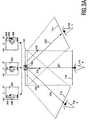
- FIG. 4Aschematically shows a display system 400 according to the invention comprising a number of sensing means 402 - 410 being disposed adjacent to the display device.
- the sensing of the sensing means 402 - 410might be based on acoustic, ultra-violet or radio frequency waves.
- the sensing meansare arranged to detect the presence of an object in their vicinity. If e.g. one of the sensors 406 which is disposed at the left side of the display device 102 detects the presence of an object, then the application which controls the view in the corresponding direction is provided with user-input.
- Sensing means based on lightare commercially available, e.g. at IVO GmbH & Co. Typically these optical sensing means are arranged to measure a distance. These sensing means are so-called proximity detectors.
- the appliance of these sensing means in the display system according to the inventionis as follows. If e.g. a hand is put in the neighborhood of the display device 102 in order to provide the display system with user input then one or multiple of the sensors detect that there is an object close to the one or multiple sensors. So, each of the sensors measures the distance of objects in their respective neighborhoods. If one of the measured distances is below a predetermined threshold and user-input is accepted by means of the user-input means at the same time then it is easily detected for which of the applications the user input is required.
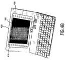
- FIG. 4Bschematically shows an apparatus 420 comprising the display system 400 according to the invention, comprising a number of sensing means 406 - 410 being disposed adjacent to the display device 102 .
- the display system 400further comprises a (not depicted) touch-sensitive screen being placed in front of the display device 102 .
- the apparatus 420further comprises a keyboard as user-input means.
- the apparatus 420further comprises a processor on which multiple applications can run simultaneously.
- a particular application which can be executed by the processoris a game for two players. When playing that game it is relevant that each of the players has its own private view. That means that the first player is not allowed to see the view of the second player and vice versa.
- the first playeris located right from the display device 102 and the second player is located left from the display device 102 .
- the playershave to provide userinput by means of touching the touch-sensitive screen.
- the touch-sensitive screenregisters user-input both the first array of ultra-sound sensors 406 which is located right from the display device 102 and the second array of ultra-sound sensors 410 which is located left from the display device 102 perform a distance measurement.
- the userinputis assumed to be provided by the first player and the application is controlled consequently.
- the user-inputis assumed to be provided by the second player and the application is controlled consequently.
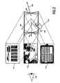
- FIG. 4Cschematically shows the inside of a car, with the display system 400 according to the invention being located in the dash-board of the car.
- FIG. 4Cshows the view 424 on the road in front of the car, the steering-wheel 422 of the driver and a mirror 426 .
- the mirror 426is optional.
- the display system 400provides a first view to the driver of the car which corresponds to images being captured by a camera which is located such that the scene behind the car can be imaged.
- the display system 400comprises sensing means 402 - 410 as described in connection with FIGS. 4A and 4B .
- the display system 400comprises cameras 106 a - 106 b being located in the ceiling and/or wall of the car.
- These cameras 106 a - 106 bare designed to observe the environment in front of the display device 102 . If one of the cameras 106 a - 106 b images an arm 412 or 416 the orientation 414 , 418 is determined. The determined orientation 414 or 418 is compared with the directions of the views of the display device 102 , as described in connection with FIG. 1 . On basis of the measurements of the sensing means 402 - 410 and the image analysis of the images captured by the cameras 106 a - 106 b the display system 400 is arranged to determine which of the persons in the car, i.e. the driver or the passenger being seated next to him, has provided userinput.
- FIG. 4Dschematically shows an apparatus comprising the display system 400 according to the invention which has to be controlled by means of pointing devices 108 - 109 .
- a device with a sharper topi.e. a pointing device 108 - 109 .
- Detection of the presence of a hand 110 - 111 which holds such a pointing device 108 - 109can be achieved similar to what has been described above. That means that the display systems according to the invention can be applied in the case that the users have a pointing device in their hand to provide user-input and in the case that they do not make use of such a pointing device.
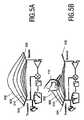
- FIGS. 5A and 5Bschematically show the concept of cross capacitance sensing.
- FIG. 5Ashows a simple combination of two electrodes 502 - 504 forming a capacitor, with a capacitive current flowing between them.
- FIG. 5Bshows the same two electrodes 502 - 504 whereby a hand 110 is placed near the electrodes 502 - 504 .
- Some of the field lines 506 - 510are terminated on the hand and the current is decreased relative to the current which flows in the case without the hand 110 being placed near the electrodes, like in FIG. 5A .
- a measurable effectcan be obtained in which the spatial range is roughly equivalent to the separation between the electrodes 502 - 504 .
- Arrays of multiple electrodesoffer rich possibilities for object and gesture recognition.
- n transmitters and n receivers arranged around the edge of a displaycontain n2 electrode pairs at many different separations. See for more details the article “3D Touchless Display Interaction”, by C. van Berkel, in SID Proceedings International Symposium, vol. 33, number 2, pp 1410-1413, 2002.
- FIG. 6schematically shows an embodiment according to the invention which is arranged to determine a trajectory 600 of a hand of an user.
- a trajectory 600 of movementBy localizing the positions 110 a - 110 c of a hand as function of time a trajectory 600 of movement can be computed.
- the localization of the different positions 110 a - 1110 c of the handmight be based on images being captured as described in connection with FIG. 1 , distances being measured as described in connection with FIGS. 4A and 4B , or based on differences in electrical fields as described in connection with FIGS. 5A and 5B .
- the trajectory 600 of the handis compared with the first 120 and second 122 view of the display device 102 .
- the best matching directioncorresponds to the view which is controlled as a result of user-input being accepted in a predetermined time interval after the computation of the trajectory 600 has finished.
- FIG. 7schematically shows a display system 700 according to the invention, comprising:
- the observation means 106 and the user-input means 104are combined. Or in other words, the user-input means 104 and observation means 106 share a number of components. That means that the display system 700 according to the invention, has means 20 704 which are arranged to determine to which part of the display device 102 is pointed to, at a particular moment and to determine what the relative position is of the person who is pointing to the display device 102 at that particular time. These means 704 are e.g. arranged to determine the position of the finger-tip and to estimate the orientation of the hand. This can for example be based on a number of images taken from different directions. This is disclosed in the article “Driving a 3D Articulated Hand Model in Real-Time using video Input”, by J.
- both parametersi.e. location of the finger-tip and orientation of the hand are determined by means of electromagnetic fields as disclosed in the article “3D Touchless Display Interaction”, by C. van Berkel, in SID Proceedings International Symposium, vol. 33, number 2, pp 1410-1413, 2002.
- transducersare applied which provide data to reconstruct three dimensional image data sets.
- any reference signs placed between parenthesesshall not be constructed as limiting the claim.
- the word ‘comprising’does not exclude the presence of elements or steps not listed in a claim.
- the word “a” or “an” preceding an elementdoes not exclude the presence of a plurality of such elements.
- the inventioncan be implemented by means of hardware comprising several distinct elements and by means of a suitable programmed computer. In the unit claims enumerating several means, several of these means can be embodied by one and the same item of hardware.
Landscapes
- Engineering & Computer Science (AREA)
- Theoretical Computer Science (AREA)
- General Engineering & Computer Science (AREA)
- Physics & Mathematics (AREA)
- Computer Hardware Design (AREA)
- General Physics & Mathematics (AREA)
- Human Computer Interaction (AREA)
- Mechanical Engineering (AREA)
- Chemical & Material Sciences (AREA)
- Transportation (AREA)
- Combustion & Propulsion (AREA)
- Multimedia (AREA)
- Signal Processing (AREA)
- Mathematical Physics (AREA)
- Optics & Photonics (AREA)
- User Interface Of Digital Computer (AREA)
- Position Input By Displaying (AREA)
- Pharmaceuticals Containing Other Organic And Inorganic Compounds (AREA)
Abstract
Description
- a display device being arranged to generate a first view in a first direction relative to the display device and to generate a second view in a second direction relative to the display device, the second direction being different from the first direction; and
- user-input means for accepting user-input by means of detecting a position of a hand of an user or of a pointing device held by the hand, the position relative to the display device, the user-input means being arranged to control the first view and the second view on basis of the detection.
- a
display device 102 being arranged to generate afirst view 112 in afirst direction 120 relative to thedisplay device 120 and to generate asecond view 114 in asecond direction 122 relative to thedisplay device 102, thesecond direction 122 being different from thefirst direction 120; - user-input means104 for accepting user-input by means of detecting a position of a
hand 110 of an user or of apointing device 108 held by the band, the position relative to thedisplay device 102. The user-input means104 are arranged to control thefirst view 112 and thesecond view 114 on basis of the detection of the position of thehand 110 of or of thepointing device 108; and - observation means106 for observation of the
users second view 114.
- a
- a
display device 102 being arranged to generate a first view in a first direction relative to the display device and to generate a second view in a second direction relative to the display device; - user-input means104 for accepting user-input by means of detecting a position of a hand of an user or of a pointing device held by the hand, relative to the display device. The user-input means104 are arranged to control a
first application 706 corresponding to the first view and to control asecond application 708 corresponding to the second view on basis of the detected position; - observation means106 for observation of the user and arranged to detect whether the user-input is provided to control the
first application 706 or thesecond application 708, on basis of the observation; and - computing means for running the first706 and the second708 application.
- a
Claims (18)
Applications Claiming Priority (4)
| Application Number | Priority Date | Filing Date | Title |
|---|---|---|---|
| EP03100596 | 2003-03-10 | ||
| EP03100596.0 | 2003-03-10 | ||
| EP03100596 | 2003-03-10 | ||
| PCT/IB2004/050159WO2004081777A1 (en) | 2003-03-10 | 2004-02-27 | Multi-view display |
Publications (2)
| Publication Number | Publication Date |
|---|---|
| US20060279528A1 US20060279528A1 (en) | 2006-12-14 |
| US7847786B2true US7847786B2 (en) | 2010-12-07 |
Family
ID=32981902
Family Applications (1)
| Application Number | Title | Priority Date | Filing Date |
|---|---|---|---|
| US10/548,242Expired - Fee RelatedUS7847786B2 (en) | 2003-03-10 | 2004-02-27 | Multi-view display |
Country Status (8)
| Country | Link |
|---|---|
| US (1) | US7847786B2 (en) |
| EP (1) | EP1604266B1 (en) |
| JP (1) | JP2006522397A (en) |
| KR (1) | KR20050110667A (en) |
| CN (1) | CN100340952C (en) |
| AT (1) | ATE386973T1 (en) |
| DE (1) | DE602004011907D1 (en) |
| WO (1) | WO2004081777A1 (en) |
Cited By (5)
| Publication number | Priority date | Publication date | Assignee | Title |
|---|---|---|---|---|
| US20090002342A1 (en)* | 2006-02-03 | 2009-01-01 | Tomohiro Terada | Information Processing Device |
| US20090243999A1 (en)* | 2005-10-07 | 2009-10-01 | Matsushita Electric Industrial Co., Ltd. | Data processing device |
| US20090262045A1 (en)* | 2006-04-14 | 2009-10-22 | Fujitsu Ten Limited | In-Vehicle Display Apparatus |
| WO2013055997A1 (en)* | 2011-10-14 | 2013-04-18 | Autodesk, Inc. | Enhanced target selection for a touch-based input enabled user interface |
| US20140325431A1 (en)* | 2013-04-30 | 2014-10-30 | Microsoft Corporation | Auto-grouping of application windows |
Families Citing this family (93)
| Publication number | Priority date | Publication date | Assignee | Title |
|---|---|---|---|---|
| JP4671591B2 (en)* | 2003-09-12 | 2011-04-20 | シャープ株式会社 | Information processing device |
| US8059099B2 (en)* | 2006-06-02 | 2011-11-15 | Apple Inc. | Techniques for interactive input to portable electronic devices |
| JP4566596B2 (en)* | 2004-03-29 | 2010-10-20 | アルパイン株式会社 | Operation instruction device |
| WO2006046783A1 (en)* | 2004-10-27 | 2006-05-04 | Fujitsu Ten Limited | Display |
| US8330674B2 (en) | 2005-03-18 | 2012-12-11 | Sharp Kabushiki Kaisha | Multiplex image display device, multiplex image display computer program, and computer-readable storage medium containing the program |
| KR101195929B1 (en)* | 2005-05-20 | 2012-10-30 | 삼성전자주식회사 | Multi-channel imaging system |
| JP4628199B2 (en)* | 2005-07-01 | 2011-02-09 | アルパイン株式会社 | Display device |
| GB2428153A (en)* | 2005-07-08 | 2007-01-17 | Sharp Kk | Interactive multiple view display |
| US7620316B2 (en)* | 2005-11-28 | 2009-11-17 | Navisense | Method and device for touchless control of a camera |
| US7774851B2 (en)* | 2005-12-22 | 2010-08-10 | Scenera Technologies, Llc | Methods, systems, and computer program products for protecting information on a user interface based on a viewability of the information |
| JP4597871B2 (en)* | 2006-01-05 | 2010-12-15 | 富士フイルム株式会社 | Digital camera |
| JP4545212B2 (en)* | 2006-02-23 | 2010-09-15 | パイオニア株式会社 | Operation input device |
| WO2007105337A1 (en)* | 2006-03-14 | 2007-09-20 | Sharp Kabushiki Kaisha | Display system, display device, display method, program and storage medium |
| US20070262953A1 (en)* | 2006-05-15 | 2007-11-15 | Zackschewski Shawn R | Multiple-view display system having user manipulation control and method |
| US20070282783A1 (en)* | 2006-05-31 | 2007-12-06 | Mona Singh | Automatically determining a sensitivity level of a resource and applying presentation attributes to the resource based on attributes of a user environment |
| JP4282694B2 (en)* | 2006-07-06 | 2009-06-24 | シャープ株式会社 | Display device and electronic apparatus provided with the display device |
| JP2008015900A (en)* | 2006-07-07 | 2008-01-24 | Xanavi Informatics Corp | Vehicle-mounted device |
| JP4984748B2 (en)* | 2006-08-30 | 2012-07-25 | 株式会社デンソー | Operator determination device and in-vehicle device provided with operator determination device |
| DE102007011543A1 (en) | 2006-08-31 | 2008-03-06 | Volkswagen Ag | Method for operating equipment of a vehicle and operating device for such devices |
| JP2008113800A (en)* | 2006-11-02 | 2008-05-22 | Toshiba Corp | Ultrasonic diagnostic equipment |
| JP5651335B2 (en)* | 2007-01-29 | 2015-01-14 | ジョンソン・コントロールズ・ゲー・エム・ベー・ハー | Operation equipment for vehicles |
| DE102007015878A1 (en)* | 2007-04-02 | 2008-10-09 | Robert Bosch Gmbh | Operating unit and operating method |
| JP4382837B2 (en)* | 2007-06-07 | 2009-12-16 | シャープ株式会社 | Display system and image processing apparatus |
| DE102007034272A1 (en) | 2007-07-19 | 2009-01-22 | Volkswagen Ag | Display and operating device for a motor vehicle with a multi-view display device |
| JP4991458B2 (en)* | 2007-09-04 | 2012-08-01 | キヤノン株式会社 | Image display apparatus and control method thereof |
| JP5453717B2 (en)* | 2008-01-10 | 2014-03-26 | 株式会社ニコン | Information display device |
| GB2457691A (en)* | 2008-02-21 | 2009-08-26 | Sharp Kk | Display with regions simultaneously operable in different viewing modes |
| US20130075579A1 (en)* | 2008-03-10 | 2013-03-28 | Lite-On Semiconductor Corp. | Electromagnetic wave sensing apparatus with integration of multiple sensors and method thereof |
| NO331839B1 (en)* | 2008-05-30 | 2012-04-16 | Cisco Systems Int Sarl | Procedure for displaying an image on a display |
| US20100073306A1 (en)* | 2008-09-25 | 2010-03-25 | Panasonic Automotive Systems Company Of America, Division Of Panasonic Corporation Of North America | Dual-view touchscreen display system and method of operation |
| DE102009006448B4 (en) | 2009-01-29 | 2019-01-31 | Volkswagen Ag | A method for determining a seating position of an occupant in a vehicle, control element for a vehicle, operating system for a vehicle and vehicle |
| JP5042258B2 (en)* | 2009-03-23 | 2012-10-03 | シャープ株式会社 | Information processing device |
| DE102009018682A1 (en)* | 2009-04-23 | 2010-10-28 | Bayerische Motoren Werke Aktiengesellschaft | Control device for motor vehicle, has control unit which is arranged in common range from driver and front passenger and by which control operation is executable for communication device |
| DE102009018681A1 (en)* | 2009-04-23 | 2010-10-28 | Bayerische Motoren Werke Aktiengesellschaft | Control device for motor vehicle, has control unit for executing control process for communication device, where extent of to-be-made available control options is reduced to one level that is consistent with respective traffic situation |
| US20100293502A1 (en)* | 2009-05-15 | 2010-11-18 | Lg Electronics Inc. | Mobile terminal equipped with multi-view display and method of controlling the mobile terminal |
| KR101590364B1 (en)* | 2009-05-22 | 2016-02-01 | 엘지전자 주식회사 | Mobile terminal with multi-view display and control method thereof |
| KR101590363B1 (en)* | 2009-05-15 | 2016-02-01 | 엘지전자 주식회사 | Mobile terminal equipped with multi-view display and control method thereof |
| US20100328221A1 (en)* | 2009-06-24 | 2010-12-30 | Nokia Corporation | Multiview display |
| DE102009032069A1 (en)* | 2009-07-07 | 2011-01-13 | Volkswagen Aktiengesellschaft | Method and device for providing a user interface in a vehicle |
| US9079498B2 (en) | 2009-10-05 | 2015-07-14 | Tesla Motors, Inc. | Morphing vehicle user interface |
| US8818624B2 (en) | 2009-10-05 | 2014-08-26 | Tesla Motors, Inc. | Adaptive soft buttons for a vehicle user interface |
| US8892299B2 (en)* | 2009-10-05 | 2014-11-18 | Tesla Motors, Inc. | Vehicle user interface with proximity activation |
| CN102053732A (en)* | 2009-11-04 | 2011-05-11 | 鸿富锦精密工业(深圳)有限公司 | Hand input light pen and optical touch control system with same |
| KR101634388B1 (en)* | 2009-12-07 | 2016-06-28 | 엘지전자 주식회사 | Method for displaying broadcasting data and mobile terminal thereof |
| US8717360B2 (en)* | 2010-01-29 | 2014-05-06 | Zspace, Inc. | Presenting a view within a three dimensional scene |
| FR2960076B1 (en)* | 2010-05-12 | 2012-06-15 | Pi Corporate | METHOD AND SYSTEM FOR NON-CONTACT ACQUISITION OF MOVEMENTS OF AN OBJECT. |
| EP2444882A1 (en) | 2010-10-05 | 2012-04-25 | Koninklijke Philips Electronics N.V. | Multi-view display |
| WO2012117508A1 (en) | 2011-02-28 | 2012-09-07 | 株式会社Pfu | Information processing device, method and program |
| KR20160084502A (en) | 2011-03-29 | 2016-07-13 | 퀄컴 인코포레이티드 | Modular mobile connected pico projectors for a local multi-user collaboration |
| US20120280900A1 (en)* | 2011-05-06 | 2012-11-08 | Nokia Corporation | Gesture recognition using plural sensors |
| JP5298161B2 (en)* | 2011-06-13 | 2013-09-25 | シャープ株式会社 | Operating device and image forming apparatus |
| WO2012177260A1 (en)* | 2011-06-24 | 2012-12-27 | Hewlett-Packard Development Company, L.P. | Touch discrimination using fisheye lens |
| WO2013056157A1 (en)* | 2011-10-13 | 2013-04-18 | Autodesk, Inc. | Proximity-aware multi-touch tabletop |
| US10176635B2 (en)* | 2012-06-28 | 2019-01-08 | Microsoft Technology Licensing, Llc | Saving augmented realities |
| JP5916566B2 (en)* | 2012-08-29 | 2016-05-11 | アルパイン株式会社 | Information system |
| US9183398B2 (en)* | 2012-09-20 | 2015-11-10 | Qualcomm Incorporated | Content-driven screen polarization with application sessions |
| CN103777796A (en)* | 2012-10-22 | 2014-05-07 | 联想(北京)有限公司 | Information processing method and electronic device |
| DE102012219280A1 (en)* | 2012-10-23 | 2014-04-24 | Robert Bosch Gmbh | Driver assistance system for motor car, has evaluating device selecting and displaying information of objects located outside of vehicle through display device in response to detected eye and pointing gesture of hand and/or finger of person |
| JP5950806B2 (en)* | 2012-12-06 | 2016-07-13 | 三菱電機株式会社 | Input device, information processing method, and information processing program |
| JP5950845B2 (en)* | 2013-02-07 | 2016-07-13 | 三菱電機株式会社 | Input device, information processing method, and information processing program |
| US10175483B2 (en)* | 2013-06-18 | 2019-01-08 | Microsoft Technology Licensing, Llc | Hybrid world/body locked HUD on an HMD |
| DE102013011533B4 (en) | 2013-07-10 | 2015-07-02 | Audi Ag | Detecting device for determining a position of an object in an interior of a motor vehicle |
| KR20150028619A (en)* | 2013-09-06 | 2015-03-16 | 현대자동차주식회사 | Misrecognition reducing type motion recognition apparatus and method thereof |
| DE102013019200A1 (en) | 2013-11-15 | 2015-05-21 | Audi Ag | Method for operating an operating system, operating system and device with an operating system |
| WO2015083267A1 (en)* | 2013-12-05 | 2015-06-11 | 三菱電機株式会社 | Display control device, and display control method |
| US10466657B2 (en) | 2014-04-03 | 2019-11-05 | Honda Motor Co., Ltd. | Systems and methods for global adaptation of an implicit gesture control system |
| US9342797B2 (en) | 2014-04-03 | 2016-05-17 | Honda Motor Co., Ltd. | Systems and methods for the detection of implicit gestures |
| US10409382B2 (en) | 2014-04-03 | 2019-09-10 | Honda Motor Co., Ltd. | Smart tutorial for gesture control system |
| US10156906B2 (en) | 2014-10-13 | 2018-12-18 | Honda Motor Co., Ltd. | Systems and methods for distinguishing gestures |
| DE102014016222A1 (en) | 2014-10-31 | 2016-05-04 | Audi Ag | Method and system for operating a touch-sensitive display device of a motor vehicle |
| US9703472B2 (en)* | 2015-03-18 | 2017-07-11 | Alpine Electronics, Inc. | Method and system for operating console with touch screen |
| DE102017203167B4 (en)* | 2017-02-27 | 2018-10-11 | Audi Ag | display |
| WO2019143729A1 (en) | 2018-01-16 | 2019-07-25 | Pacific Light & Hologram, Inc. | Three-dimensional displays using electromagnetic field computations |
| JP7345400B2 (en)* | 2020-01-17 | 2023-09-15 | シャープ株式会社 | Image forming apparatus, control program and control method |
| US11360430B2 (en) | 2020-09-17 | 2022-06-14 | Pacific Light & Hologram, Inc. | Reconstructing objects with display zero order light suppression |
| DE102021120856B3 (en)* | 2021-08-11 | 2022-08-18 | Audi Aktiengesellschaft | Method for operating a display device of a motor vehicle, motor vehicle and control device |
| DE102022105769A1 (en) | 2022-03-11 | 2023-09-14 | Audi Aktiengesellschaft | Operating a touch-sensitive multiview display screen |
| US12243453B2 (en) | 2023-05-12 | 2025-03-04 | Pacific Light & Hologram, Inc. | Holographically displaying three-dimensional objects |
| US12236816B2 (en) | 2023-05-12 | 2025-02-25 | Pacific Light & Hologram, Inc. | Holographically displaying live scenes including three-dimensional objects |
| US12266279B2 (en) | 2023-05-12 | 2025-04-01 | Pacific Light & Hologram, Inc. | Holographically displaying three-dimensional objects with optical devices having in-coupling and out-coupling diffractive structures |
| US12254797B2 (en) | 2023-05-12 | 2025-03-18 | Pacific Light & Hologram, Inc. | Holographically displaying live scenes including three-dimensional objects |
| US12293687B2 (en) | 2023-05-12 | 2025-05-06 | Pacific Light & Hologram, Inc. | Holographically displaying live scenes including three-dimensional objects |
| US12300132B2 (en) | 2023-05-12 | 2025-05-13 | Pacific Light & Hologram, Inc. | Holographically displaying three-dimensional objects |
| US12374247B2 (en) | 2023-05-12 | 2025-07-29 | Pacific Light & Hologram, Inc. | Holographically displaying live scenes including three-dimensional objects |
| US11900842B1 (en) | 2023-05-12 | 2024-02-13 | Pacific Light & Hologram, Inc. | Irregular devices |
| US12266280B2 (en) | 2023-05-12 | 2025-04-01 | Pacific Light & Hologram, Inc. | Holographically displaying three-dimensional objects |
| US12254798B2 (en) | 2023-05-12 | 2025-03-18 | Pacific Light & Hologram, Inc. | Holographically displaying three-dimensional objects |
| US12230176B2 (en) | 2023-05-12 | 2025-02-18 | Pacific Light & Hologram, Inc. | Holographically displaying three-dimensional objects |
| US12315403B2 (en) | 2023-05-12 | 2025-05-27 | Pacific Light & Hologram, Inc. | Holographically displaying three-dimensional objects |
| US12272279B2 (en) | 2023-05-12 | 2025-04-08 | Pacific Light & Hologram, Inc. | Holographically displaying three-dimensional objects |
| US12288490B2 (en) | 2023-05-12 | 2025-04-29 | Pacific Light & Hologram, Inc. | Holographically displaying three-dimensional objects |
| EP4521201A1 (en)* | 2023-09-11 | 2025-03-12 | Harman Becker Automotive Systems GmbH | User input device |
| US12281984B1 (en) | 2023-12-21 | 2025-04-22 | Pacific Light & Hologram, Inc. | Optical measurements |
Citations (14)
| Publication number | Priority date | Publication date | Assignee | Title |
|---|---|---|---|---|
| EP0571702A2 (en) | 1992-05-26 | 1993-12-01 | Takenaka Corporation | Hand pointing type input unit and wall computer module |
| JPH07103784A (en)* | 1993-10-04 | 1995-04-18 | Honda Motor Co Ltd | Vehicle information display device |
| JPH08152992A (en)* | 1994-11-30 | 1996-06-11 | Toshiba Corp | Display control method and display control system |
| US5867223A (en) | 1995-07-17 | 1999-02-02 | Gateway 2000, Inc. | System for assigning multichannel audio signals to independent wireless audio output devices |
| US5883739A (en)* | 1993-10-04 | 1999-03-16 | Honda Giken Kogyo Kabushiki Kaisha | Information display device for vehicle |
| EP0931574A1 (en) | 1998-01-17 | 1999-07-28 | Interactive Studios Ltd. | Viewing area divider for a display device such as a monitor or tv screen |
| US5959612A (en) | 1994-02-15 | 1999-09-28 | Breyer; Branko | Computer pointing device |
| US6069649A (en) | 1994-08-05 | 2000-05-30 | Hattori; Tomohiko | Stereoscopic display |
| US6133944A (en) | 1995-12-18 | 2000-10-17 | Telcordia Technologies, Inc. | Head mounted displays linked to networked electronic panning cameras |
| WO2001047247A2 (en) | 1999-12-22 | 2001-06-28 | Koninklijke Philips Electronics N.V. | Multiple window display system |
| US20020024500A1 (en)* | 1997-03-06 | 2002-02-28 | Robert Bruce Howard | Wireless control device |
| WO2002020110A1 (en) | 2000-09-08 | 2002-03-14 | Sylvius | Multiuser electronic platform-screen, in particular for games, and method for controlling clearance for executing programmes such as games |
| US20030038754A1 (en)* | 2001-08-22 | 2003-02-27 | Mikael Goldstein | Method and apparatus for gaze responsive text presentation in RSVP display |
| US6890077B2 (en)* | 2002-11-27 | 2005-05-10 | The Boeing Company | Method and apparatus for high resolution video image display |
Family Cites Families (7)
| Publication number | Priority date | Publication date | Assignee | Title |
|---|---|---|---|---|
| JPH05324181A (en)* | 1992-05-26 | 1993-12-07 | Takenaka Komuten Co Ltd | Hand pointing type input device |
| JP3398999B2 (en)* | 1993-02-10 | 2003-04-21 | 株式会社デンソー | Multiplex video display |
| JP3303529B2 (en)* | 1994-06-17 | 2002-07-22 | 住友金属工業株式会社 | Electroplated steel sheet and its manufacturing method |
| JP2000137443A (en)* | 1998-11-04 | 2000-05-16 | Harness Syst Tech Res Ltd | Display device for vehicles |
| JP2000346651A (en)* | 1999-06-07 | 2000-12-15 | Tokai Rika Co Ltd | Display system |
| JP2003140595A (en)* | 2001-11-02 | 2003-05-16 | Noritsu Koki Co Ltd | Method and device for image display |
| JP2004233816A (en)* | 2003-01-31 | 2004-08-19 | Olympus Corp | Image display device and image display method |
- 2004
- 2004-02-27USUS10/548,242patent/US7847786B2/ennot_activeExpired - Fee Related
- 2004-02-27EPEP04715431Apatent/EP1604266B1/ennot_activeExpired - Lifetime
- 2004-02-27KRKR1020057016929Apatent/KR20050110667A/ennot_activeWithdrawn
- 2004-02-27ATAT04715431Tpatent/ATE386973T1/ennot_activeIP Right Cessation
- 2004-02-27WOPCT/IB2004/050159patent/WO2004081777A1/enactiveIP Right Grant
- 2004-02-27CNCNB2004800064563Apatent/CN100340952C/ennot_activeExpired - Fee Related
- 2004-02-27DEDE602004011907Tpatent/DE602004011907D1/ennot_activeExpired - Lifetime
- 2004-02-27JPJP2006506649Apatent/JP2006522397A/enactivePending
Patent Citations (14)
| Publication number | Priority date | Publication date | Assignee | Title |
|---|---|---|---|---|
| EP0571702A2 (en) | 1992-05-26 | 1993-12-01 | Takenaka Corporation | Hand pointing type input unit and wall computer module |
| JPH07103784A (en)* | 1993-10-04 | 1995-04-18 | Honda Motor Co Ltd | Vehicle information display device |
| US5883739A (en)* | 1993-10-04 | 1999-03-16 | Honda Giken Kogyo Kabushiki Kaisha | Information display device for vehicle |
| US5959612A (en) | 1994-02-15 | 1999-09-28 | Breyer; Branko | Computer pointing device |
| US6069649A (en) | 1994-08-05 | 2000-05-30 | Hattori; Tomohiko | Stereoscopic display |
| JPH08152992A (en)* | 1994-11-30 | 1996-06-11 | Toshiba Corp | Display control method and display control system |
| US5867223A (en) | 1995-07-17 | 1999-02-02 | Gateway 2000, Inc. | System for assigning multichannel audio signals to independent wireless audio output devices |
| US6133944A (en) | 1995-12-18 | 2000-10-17 | Telcordia Technologies, Inc. | Head mounted displays linked to networked electronic panning cameras |
| US20020024500A1 (en)* | 1997-03-06 | 2002-02-28 | Robert Bruce Howard | Wireless control device |
| EP0931574A1 (en) | 1998-01-17 | 1999-07-28 | Interactive Studios Ltd. | Viewing area divider for a display device such as a monitor or tv screen |
| WO2001047247A2 (en) | 1999-12-22 | 2001-06-28 | Koninklijke Philips Electronics N.V. | Multiple window display system |
| WO2002020110A1 (en) | 2000-09-08 | 2002-03-14 | Sylvius | Multiuser electronic platform-screen, in particular for games, and method for controlling clearance for executing programmes such as games |
| US20030038754A1 (en)* | 2001-08-22 | 2003-02-27 | Mikael Goldstein | Method and apparatus for gaze responsive text presentation in RSVP display |
| US6890077B2 (en)* | 2002-11-27 | 2005-05-10 | The Boeing Company | Method and apparatus for high resolution video image display |
Non-Patent Citations (2)
| Title |
|---|
| Cees Van Berkel: P-55.1: 3D Touchless Display Interaction, May 2002, pp. 1-4. |
| J. Segen, et al: Driving a 3D Articulated Hand Model in Real-Time Using Video Input, Jul. 1998. |
Cited By (14)
| Publication number | Priority date | Publication date | Assignee | Title |
|---|---|---|---|---|
| US20090243999A1 (en)* | 2005-10-07 | 2009-10-01 | Matsushita Electric Industrial Co., Ltd. | Data processing device |
| US20090002342A1 (en)* | 2006-02-03 | 2009-01-01 | Tomohiro Terada | Information Processing Device |
| US20090262045A1 (en)* | 2006-04-14 | 2009-10-22 | Fujitsu Ten Limited | In-Vehicle Display Apparatus |
| US8373620B2 (en)* | 2006-04-14 | 2013-02-12 | Fujitsu Ten Limited | In-vehicle display apparatus |
| WO2013055997A1 (en)* | 2011-10-14 | 2013-04-18 | Autodesk, Inc. | Enhanced target selection for a touch-based input enabled user interface |
| US10684768B2 (en) | 2011-10-14 | 2020-06-16 | Autodesk, Inc. | Enhanced target selection for a touch-based input enabled user interface |
| US9250761B2 (en)* | 2013-04-30 | 2016-02-02 | Microsoft Technology Licensing, Llc | Auto-grouping of application windows |
| US20160103600A1 (en)* | 2013-04-30 | 2016-04-14 | Microsoft Technology Licensing, Llc | Auto-grouping of application windows |
| US9575643B2 (en)* | 2013-04-30 | 2017-02-21 | Microsoft Technology Licensing, Llc | Auto-grouping of application windows |
| US20170371530A1 (en)* | 2013-04-30 | 2017-12-28 | Microsoft Technology Licensing, Llc | Auto-grouping of application windows |
| US10528242B2 (en)* | 2013-04-30 | 2020-01-07 | Microsoft Technology Licensing, Llc | Auto-grouping of application windows |
| US20200117355A1 (en)* | 2013-04-30 | 2020-04-16 | Microsoft Technology Licensing, Llc | Auto-grouping of application windows |
| US20140325431A1 (en)* | 2013-04-30 | 2014-10-30 | Microsoft Corporation | Auto-grouping of application windows |
| US11003347B2 (en)* | 2013-04-30 | 2021-05-11 | Microsoft Technology Licensing, Llc | Auto-grouping of application windows |
Also Published As
| Publication number | Publication date |
|---|---|
| EP1604266B1 (en) | 2008-02-20 |
| CN1759370A (en) | 2006-04-12 |
| US20060279528A1 (en) | 2006-12-14 |
| EP1604266A1 (en) | 2005-12-14 |
| DE602004011907D1 (en) | 2008-04-03 |
| CN100340952C (en) | 2007-10-03 |
| ATE386973T1 (en) | 2008-03-15 |
| WO2004081777A1 (en) | 2004-09-23 |
| KR20050110667A (en) | 2005-11-23 |
| JP2006522397A (en) | 2006-09-28 |
Similar Documents
| Publication | Publication Date | Title |
|---|---|---|
| US7847786B2 (en) | Multi-view display | |
| CN104765445B (en) | Eye vergence detection on a display | |
| US20110260965A1 (en) | Apparatus and method of user interface for manipulating multimedia contents in vehicle | |
| US20180356896A1 (en) | Systems and methods for proximity sensor and image sensor based gesture detection | |
| EP2927634B1 (en) | Single-camera ranging method and system | |
| JP6480434B2 (en) | System and method for direct pointing detection for interaction with digital devices | |
| US20200201436A1 (en) | Method and device for providing haptic feedback in virtual reality system | |
| US10611308B2 (en) | Image generation device and image generation method | |
| WO2009139214A1 (en) | Display device and control method | |
| US20100026723A1 (en) | Image magnification system for computer interface | |
| US20150009119A1 (en) | Built-in design of camera system for imaging and gesture processing applications | |
| KR101441882B1 (en) | method for controlling electronic devices by using virtural surface adjacent to display in virtual touch apparatus without pointer | |
| JPH1124603A (en) | Information display device and information collecting device | |
| US20120092332A1 (en) | Input device, input control system, method of processing information, and program | |
| CN109669530A (en) | Vibrating tactile drive circuit for haptic apparatus | |
| CN111862148A (en) | Method, device, electronic equipment and medium for realizing visual tracking | |
| JP4753752B2 (en) | In-vehicle electronic device and menu providing method | |
| WO2014103217A1 (en) | Operation device and operation detection method | |
| JP2008052536A (en) | Touch panel type input device | |
| US20210089199A1 (en) | Interactive stereoscopic display and interactive sensing method for the same | |
| US10345595B2 (en) | Head mounted device with eye tracking and control method thereof | |
| TWI454653B (en) | Systems and methods for determining three-dimensional absolute coordinates of objects | |
| JP2015114682A (en) | Touch panel device | |
| WO2015064991A2 (en) | Smart device enabling non-contact operation control and non-contact operation control method using same | |
| US20250306675A1 (en) | Method and apparatus for moving virtual object, electronic device, and storage medium |
Legal Events
| Date | Code | Title | Description |
|---|---|---|---|
| AS | Assignment | Owner name:KONINKLIJKE PHILIPS ELECTRONICS, N.V., NETHERLANDS Free format text:ASSIGNMENT OF ASSIGNORS INTEREST;ASSIGNORS:SCHOBBEN, DANIEL WILLEM ELISABETH;WILINSKI, PIOTR;VAN DELDEN, MARTINUS HERMANUS WILHELMUS MARIA;AND OTHERS;SIGNING DATES FROM 20041007 TO 20041014;REEL/FRAME:017747/0350 Owner name:KONINKLIJKE PHILIPS ELECTRONICS, N.V., NETHERLANDS Free format text:ASSIGNMENT OF ASSIGNORS INTEREST;ASSIGNORS:SCHOBBEN, DANIEL WILLEM ELISABETH;WILINSKI, PIOTR;VAN DELDEN, MARTINUS HERMANUS WILHELMUS MARIA;AND OTHERS;REEL/FRAME:017747/0350;SIGNING DATES FROM 20041007 TO 20041014 | |
| STCF | Information on status: patent grant | Free format text:PATENTED CASE | |
| FPAY | Fee payment | Year of fee payment:4 | |
| FEPP | Fee payment procedure | Free format text:MAINTENANCE FEE REMINDER MAILED (ORIGINAL EVENT CODE: REM.) | |
| FEPP | Fee payment procedure | Free format text:7.5 YR SURCHARGE - LATE PMT W/IN 6 MO, LARGE ENTITY (ORIGINAL EVENT CODE: M1555); ENTITY STATUS OF PATENT OWNER: LARGE ENTITY | |
| MAFP | Maintenance fee payment | Free format text:PAYMENT OF MAINTENANCE FEE, 8TH YEAR, LARGE ENTITY (ORIGINAL EVENT CODE: M1552); ENTITY STATUS OF PATENT OWNER: LARGE ENTITY Year of fee payment:8 | |
| FEPP | Fee payment procedure | Free format text:MAINTENANCE FEE REMINDER MAILED (ORIGINAL EVENT CODE: REM.); ENTITY STATUS OF PATENT OWNER: LARGE ENTITY | |
| LAPS | Lapse for failure to pay maintenance fees | Free format text:PATENT EXPIRED FOR FAILURE TO PAY MAINTENANCE FEES (ORIGINAL EVENT CODE: EXP.); ENTITY STATUS OF PATENT OWNER: LARGE ENTITY | |
| STCH | Information on status: patent discontinuation | Free format text:PATENT EXPIRED DUE TO NONPAYMENT OF MAINTENANCE FEES UNDER 37 CFR 1.362 | |
| FP | Lapsed due to failure to pay maintenance fee | Effective date:20221207 |