US7847709B2 - Multimode vehicle location device and method - Google Patents
Multimode vehicle location device and methodDownload PDFInfo
- Publication number
- US7847709B2 US7847709B2US11/845,836US84583607AUS7847709B2US 7847709 B2US7847709 B2US 7847709B2US 84583607 AUS84583607 AUS 84583607AUS 7847709 B2US7847709 B2US 7847709B2
- Authority
- US
- United States
- Prior art keywords
- vehicle
- information
- location
- user
- parked
- Prior art date
- Legal status (The legal status is an assumption and is not a legal conclusion. Google has not performed a legal analysis and makes no representation as to the accuracy of the status listed.)
- Active, expires
Links
- 238000000034methodMethods0.000titleclaimsabstractdescription74
- 230000004044responseEffects0.000claimsabstractdescription10
- 230000033001locomotionEffects0.000claimsdescription20
- 230000006870functionEffects0.000claimsdescription11
- 230000003213activating effectEffects0.000claimsdescription3
- 239000003086colorantSubstances0.000claimsdescription2
- 230000008569processEffects0.000description11
- 230000000007visual effectEffects0.000description7
- 230000005540biological transmissionEffects0.000description5
- 238000012545processingMethods0.000description5
- 238000004891communicationMethods0.000description4
- 238000010586diagramMethods0.000description4
- 230000000881depressing effectEffects0.000description2
- 230000000994depressogenic effectEffects0.000description2
- 230000009977dual effectEffects0.000description2
- 239000000446fuelSubstances0.000description2
- 230000007774longtermEffects0.000description2
- 238000003032molecular dockingMethods0.000description2
- 230000037361pathwayEffects0.000description2
- 238000012546transferMethods0.000description2
- 230000001052transient effectEffects0.000description2
- 238000004458analytical methodMethods0.000description1
- 238000013459approachMethods0.000description1
- 230000008901benefitEffects0.000description1
- 230000015572biosynthetic processEffects0.000description1
- 239000003990capacitorSubstances0.000description1
- 230000001413cellular effectEffects0.000description1
- 230000008878couplingEffects0.000description1
- 238000010168coupling processMethods0.000description1
- 238000005859coupling reactionMethods0.000description1
- 230000006698inductionEffects0.000description1
- 230000003993interactionEffects0.000description1
- 239000004973liquid crystal related substanceSubstances0.000description1
- 238000012986modificationMethods0.000description1
- 230000004048modificationEffects0.000description1
- 238000012544monitoring processMethods0.000description1
- 230000003287optical effectEffects0.000description1
- 238000007557optical granulometryMethods0.000description1
- 238000003909pattern recognitionMethods0.000description1
- 239000000126substanceSubstances0.000description1
- 238000013519translationMethods0.000description1
- 230000014616translationEffects0.000description1
Images


Classifications
- G—PHYSICS
- G08—SIGNALLING
- G08G—TRAFFIC CONTROL SYSTEMS
- G08G1/00—Traffic control systems for road vehicles
- G08G1/005—Traffic control systems for road vehicles including pedestrian guidance indicator
- G—PHYSICS
- G01—MEASURING; TESTING
- G01C—MEASURING DISTANCES, LEVELS OR BEARINGS; SURVEYING; NAVIGATION; GYROSCOPIC INSTRUMENTS; PHOTOGRAMMETRY OR VIDEOGRAMMETRY
- G01C21/00—Navigation; Navigational instruments not provided for in groups G01C1/00 - G01C19/00
- G01C21/26—Navigation; Navigational instruments not provided for in groups G01C1/00 - G01C19/00 specially adapted for navigation in a road network
- G01C21/34—Route searching; Route guidance
- G01C21/36—Input/output arrangements for on-board computers
- G01C21/3626—Details of the output of route guidance instructions
- G01C21/3632—Guidance using simplified or iconic instructions, e.g. using arrows
- G—PHYSICS
- G01—MEASURING; TESTING
- G01C—MEASURING DISTANCES, LEVELS OR BEARINGS; SURVEYING; NAVIGATION; GYROSCOPIC INSTRUMENTS; PHOTOGRAMMETRY OR VIDEOGRAMMETRY
- G01C21/00—Navigation; Navigational instruments not provided for in groups G01C1/00 - G01C19/00
- G01C21/26—Navigation; Navigational instruments not provided for in groups G01C1/00 - G01C19/00 specially adapted for navigation in a road network
- G01C21/34—Route searching; Route guidance
- G01C21/36—Input/output arrangements for on-board computers
- G01C21/3626—Details of the output of route guidance instructions
- G01C21/3647—Guidance involving output of stored or live camera images or video streams
- G—PHYSICS
- G01—MEASURING; TESTING
- G01C—MEASURING DISTANCES, LEVELS OR BEARINGS; SURVEYING; NAVIGATION; GYROSCOPIC INSTRUMENTS; PHOTOGRAMMETRY OR VIDEOGRAMMETRY
- G01C21/00—Navigation; Navigational instruments not provided for in groups G01C1/00 - G01C19/00
- G01C21/26—Navigation; Navigational instruments not provided for in groups G01C1/00 - G01C19/00 specially adapted for navigation in a road network
- G01C21/34—Route searching; Route guidance
- G01C21/36—Input/output arrangements for on-board computers
- G01C21/3679—Retrieval, searching and output of POI information, e.g. hotels, restaurants, shops, filling stations, parking facilities
- G01C21/3685—Retrieval, searching and output of POI information, e.g. hotels, restaurants, shops, filling stations, parking facilities the POI's being parking facilities
- G—PHYSICS
- G08—SIGNALLING
- G08G—TRAFFIC CONTROL SYSTEMS
- G08G1/00—Traffic control systems for road vehicles
- G08G1/09—Arrangements for giving variable traffic instructions
- G08G1/0962—Arrangements for giving variable traffic instructions having an indicator mounted inside the vehicle, e.g. giving voice messages
- G08G1/0968—Systems involving transmission of navigation instructions to the vehicle
- G08G1/0969—Systems involving transmission of navigation instructions to the vehicle having a display in the form of a map
- G—PHYSICS
- G08—SIGNALLING
- G08G—TRAFFIC CONTROL SYSTEMS
- G08G1/00—Traffic control systems for road vehicles
- G08G1/20—Monitoring the location of vehicles belonging to a group, e.g. fleet of vehicles, countable or determined number of vehicles
- G08G1/205—Indicating the location of the monitored vehicles as destination, e.g. accidents, stolen, rental
Definitions
- the present inventiongenerally relates to an apparatus and method for locating a vehicle and, more particularly, to an electronic device and method for guiding a user to a parked vehicle.
- GPSglobal positioning system
- the fob itselfalso employs a GPS positioning finding capability, this capability may also be inoperative when the fob is carried into a shopping mall, office building or other structure that is substantially opaque to the GPS signals.
- Other systemsrely on local beacons or nodes placed in known locations in and around the parking areas or structures. By tracking its location relative to these nodes the device location can be determined. However, such beacon systems may fail to function if the device is carried into an office building or other structure where the beacon signals are no longer received.
- a multi-mode electronic deviceconfigured to be carried by a user is provided for directing the user to a parked vehicle.
- the multi-mode electronic deviceutilizes, if available, GPS location data and/or node location data provided by at least one local wireless node and vehicle location information provided by the vehicle. If such primary location determining functions are not available or not desired, the device makes use of automatically or manually provided photos of familiar landmarks in the vicinity of the parked vehicle to suggest to the user how to find the vehicle. Such photos may be combined with vehicle location information when available and presented together to further enhance the ease of locating the vehicle.
- One or more cameras on the vehicleautomatically or manually record the local environment and landmarks as the vehicle is being parked and shortly thereafter.
- the electronic deviceincludes an interface desirably wirelessly coupled to the vehicle, a controller and a memory for storing and processing the photos and other information provided by the vehicle and/or generated within the device, and a display for presenting such to the user on request.
- a dead reckoning navigation system, GPS navigation system and/or cell phone navigation interfacemay be provided in the device, whereby the controller can use information therefrom when available so as to provide the desired multimode capability.
- the usermay also be presented with information on the quality (accuracy) of the location information.
- FIGS. 1-5are plan views of front faces of keyfobs having a parked vehicle location function in accordance with exemplary embodiments of the present invention and illustrating different modes of operation;
- FIG. 6is a plan view of a rear face of keyfobs such as those illustrated in FIGS. 1-5 , showing further embodiments;
- FIG. 7is a block diagram of a vehicle location system that may be incorporated into a portable electronic device, such as the keyfobs shown in FIGS. 1-6 , according to still further embodiments;
- FIG. 8is a block diagram of a vehicle mounted electronics system adapted to interface with the portable vehicle location system of FIG. 7 , according to yet further embodiments;
- FIG. 9is a flowchart illustrating an exemplary process utilized by the vehicle portion of the vehicle location system shown in FIG. 8 to provide location, photo and/or location quality information to the keyfob, according to yet still further embodiments;
- FIG. 10is a flowchart illustrating an exemplary process utilized by the keyfob portion of the vehicle location system shown in FIG. 7 to receive location, photo and/or location quality information from the vehicle and further process it and present return-to-vehicle information when requested by the user, according to still yet further embodiments of the invention.
- FIG. 11is a flowchart illustrating an exemplary process analogous to that of FIG. 10 , but according to additional embodiments of the invention
- keyfoband/or “electronic device” are intended to include these and other portable electronic apparatus, irrespective of whether or not it includes a through-hole for attachment of a key.
- keyfobor “electronic device” of the present invention, provided that it incorporates one or more of the various embodiments described herein. Aspects of the present invention are described in terms of “photos” of the vehicle environment taken automatically or manually.
- the terms “photo”, “photographic” and “image” singular or pluralare intended to have their broadest possible meaning and to include but not be limited to any type of graphical representation of a particular location or object or geographical region.
- Non limiting examplesare maps and images obtained from an electronic camera, either still or in video format, and various translations or modifications of such images as may be performed by image processing, image enhancement, adjustment of clarity or contrast or color, shading, outline or wire-frame processing, and other well known image enhancement techniques to make the images more useful for their intended purpose.
- image processingimage enhancement, adjustment of clarity or contrast or color, shading, outline or wire-frame processing, and other well known image enhancement techniques to make the images more useful for their intended purpose.
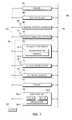
- FIGS. 1-6are plan views of keyfobs 20 - 1 , 20 - 2 , 20 - 3 , 20 - 4 , 20 - 5 , 20 - 6 having parked vehicle location functions in accordance with various exemplary embodiments of the present invention.
- the conventionis adopted of referring to the keyfobs illustrated in FIGS. 1-6 by the reference number 20 - 1 for FIG. 1 , reference number 20 - 2 for FIG. 2 , reference number 20 - 3 for FIG. 3 , reference number 20 - 4 for FIG. 4 , reference number 20 - 5 for FIG. 5 and reference number 20 - 6 for FIG. 6 , respectively, and collectively as keyfob 20 .
- FIGS. 1for FIG. 1
- 20 - 2for FIG. 2
- reference number 20 - 3for FIG. 3
- reference number 20 - 4for FIG. 4
- reference number 20 - 5for FIG. 5
- reference number 20 - 6for FIG. 6
- FIG. 1-5show the same (front) face of keyfob 20 illustrating various controls and an output screen for different modes of operation.
- FIG. 6shows the opposite (rear) face of keyfob 20 where, according to the embodiment of reference number 20 - 6 , lens 44 of camera 41 is provided so that keyfob 20 itself can be used to take photos, and annunciator 59 is also optionally provided.
- Keyfob 20comprises housing 22 having opening 25 there through that enables keyfob 20 to be attached to a key or keychain in the well-known manner. Opening 25 is desirable but not essential.
- buttons or other user activated switches 23are provided on the exterior of housing 22 and may include, for example and not intended to be limiting, DOOR LOCK button 24 , DOOR UNLOCK button 26 , REMOTE START button 28 , TRUNK UNLOCK button 30 , PANIC button 32 , FIND PARKED VEHICLE buttons 34 - 38 , and optional camera button 40 , according to several modes of operation.
- the term “button”is intended to include any form of user operable electronic switch, as for example and not intended to be limiting, a switch whose movement makes or breaks an electrical contact and various forms of proximity switches that make or break an electrical contact when a finger or stylus is brought into contact with or close to the switch, and so forth.
- camera shutter button 40is also desirably included.
- References herein to “depressing a button”are intended to include any means of activating switches 23 and not be limited merely to physical movement of a particular button or switch.
- Keyfob 20further comprises display 42 (e.g., a liquid crystal or other portable display) that may display status information (not shown) relating to a vehicle (or vehicles) associated with keyfob 20 .
- This status informationmay include the vehicle's mileage, tire pressure, current fuel level, radio station settings, door lock status, etc., as well as information related to the vehicle location.
- Scroll wheel 43is conveniently mounted on a side of housing 22 and utilized to navigate amongst such data and choices. For example, a user may rotate scroll wheel 43 to navigate between vehicular and/or vehicle location features and depress scroll wheel 43 to select a desired feature and view the information associated therewith.
- Keyfob 20also desirably but not essentially includes light bar 45 with, in this example four LEDs or other colored lights.
- the light sources in light bar 45are identified as showing show red (R), orange (O), yellow (Y) or green (G) colors when illuminated. As will be further explained, these lights are useful for providing information to the user on the quality (accuracy) of the available location information.
- keyfob 20When a user depresses any one of FIND PARKED VEHICLE buttons 34 - 38 , keyfob 20 provides visual prompts on display 42 that may guide the user back to his or her parked vehicle in the manner described below. For example, as indicated in FIG. 1 , if FIND PARKED VEHICLE button 34 of keyfob 20 - 1 is pressed, then RETURN-TO-VEHICLE information view 47 of arrow 44 may be generated on display 42 indicating the direction of the vehicle relative to the current position of keyfob 20 , if such information is available.
- an estimated keyfob-to-car distance(e.g., 123 meters or feet or other convenient unit) may also be displayed on display 42 as shown at 46 of keyfob 20 - 1 of FIG. 1 .
- Ggreen
- location informationis available but its quality is poor (e.g., because of weak GPS or local beacon signals)
- the above-mentioned criteria for identifying the various location data quality levelsare intended to merely examples and not limitations. Persons of skill in the art will understand that a wide variety of criteria for determining location information quality can be adopted depending upon the needs of the particular system and the location tracking features incorporated in the system, and that any suitable criteria can be used, including but not limited to those examples presented above.
- overhead view 48(if available) of the local parking area may be presented on display 42 with the position of the vehicle indicated at location 50 .
- This overhead viewcan be constructed by manipulating the local environment images acquired by the vehicle as it is being parked, or from images available from an off-board repository, such as a database of satellite images, or from images provided by local cameras in the parking area that are wirelessly transmitted to the vehicle (or the keyfob).
- This overhead viewcan occur onboard the vehicle using the vehicles electronic systems, or generated by a remote server (e.g., a satellite or a local parking facility security system) that wirelessly transfers the processed image to the vehicle for transfer to the fob and/or to the fob directly. Any of these arrangements is useful.
- a remote servere.g., a satellite or a local parking facility security system
- the location information qualityis good so that light bar 45 shows yellow (Y).
- FIND PARKED VEHICLE button 36is depressed, map view 52 of the local area is provided with the position of the vehicle indicated at location 54 .
- the map informationcan be stored in the vehicle as a part of its on-board navigation system or downloaded from a local beacon server or elsewhere.
- keyfob 20 - 3it assumed that the location information quality is fair so that light bar 45 shows Orange (O).
- the FIND PARKED VEHICLE location information illustrated in displays 42 of keyfobs 20 - 1 , 20 - 2 and 20 - 3 of FIGS. 1-3is most conveniently obtained by using navigation information obtained from the vehicle and/or generated within keyfob 20 , for example, from GPS or local node data, combined if necessary with GPS and/or dead reckoning data developed within keyfob 20 , as the user moves away from the vehicle.
- Such location informationcan be combined with local map information downloaded from the vehicle into the keyfob as the user exits the vehicle, to provide the information shown on displays 42 of keyfobs 20 - 1 , 20 - 2 , 20 - 3 .
- the keyfobmay be unable to provide the types of FIND PARKED VEHICLE information displays described above. In that circumstance, a further mode of operation is employed, as illustrated for example, by keyfob 20 - 4 of FIG. 4 .
- photo 54shows the front of an easily recognizable nearby landmark, e.g., U.S. Post Office 55 located between café 56 and bank 57 , from which the user could readily infer that the vehicle is parked across the street from these buildings.
- U.S. Post Office 55located between café 56 and bank 57
- keyfob 20 - 6include camera 41 (see FIG. 6 )
- the fob usermay elect to manually take a photo directly with the fob when exiting the vehicle. This insures that a user chosen, easily remembered, landmark is captured in such a photo. Taking the photo with keyfobs 20 - 4 , 20 - 5 , 20 - 6 is accomplished, for example and not intended to be limiting, by pressing button 40 , e.g., once to turn on keyfob camera 41 and a second time to record the photo. When camera 41 is turned on, photo image 54 being seen by keyfob lens 51 is shown on display 42 .
- Keyfob lens 51is conveniently but not essentially located on the opposite face of keyfob 20 - 4 , 20 - 5 from display 42 and is shown in FIG. 6 and image 54 captured thereby is shown on display 42 .
- scroll wheel 43may be used to scan through the various photo images stored in keyfob 20 - 4 , 20 - 5 whether derived from the vehicle camera(s) or keyfob camera 41 or both.
- the usermay take a sequence of photos that can be displayed in rapid succession, i.e., like a video.
- FIG. 5shows keyfob 20 - 5 illustrating another mode of operation of key keyfob 20 that can be activated by, for example and not intended to be limiting, depressing buttons 34 and 38 together.
- the RETURN-TO-VEHICLE (RTV) location informatione.g., “NW-127 Meters” legend 58 - 1 and/or directional arrow 58 - 2 , is superimposed on the photo information (e.g., on photo image 54 ).
- this dual mode of operationmay be selected as a preferred mode of operation that is stored within keyfob 20 so that only a single button need be activated to obtain it.
- this dual mode of operationmay be invoked automatically by keyfob 20 when the quality (e.g., the accuracy) of the location information falls below a predetermined standard.
- the quality of GPS or beacon node location informationdepends upon the number of satellites or nodes that are within range of the GPS navigation system receiver or the node beacon receiver, and the received signal to noise (S/N) ratios. Presentation of combined location information and photo information is explained more fully in connection with FIGS. 9 and 11 .
- the location information qualityis assumed to be poor and therefore light bar 45 shows a red (R) light, but this is not essential.
- Keyfob 20 of FIGS. 1-6preferably communicate with the associated vehicle(s) via radiofrequency signals; however, it should be appreciated that other wireless and non-communications means may be utilized as well, including, but not limited to, an induction-based means, a low frequency (e.g., 10-300 kHz) communication means or an optical wireless means.
- an induction-based meanse.g., a low frequency (e.g., 10-300 kHz) communication means or an optical wireless means.
- embodimentsmay comprise a keyfob that communicates with a vehicle over a hard wire connection; e.g., a keyfob that carries an electrical connector (e.g., a D-subminiature connector, a multi-pin USB connector similar to that employed by a portable flash drive device, etc.) that permits electrical communication with the vehicle when the keyfob is inserted into a docking station in the vehicle.
- an electrical connectore.g., a D-subminiature connector, a multi-pin USB connector similar to that employed by a portable flash drive device, etc.
- FIGS. 1-6employing visual display 42 adapted to provide graphic images and/or photos
- keyfob 20may utilize other visual indications to guide a user back to the vehicle.
- light bar 45may be used as a direction indicator in addition to its function as a quality indicator.
- keyfob 20may produce audible signals in addition to or in lieu of visual signals, as for example by means of annunciator 59 of FIG. 6 .
- a non-limiting example of such non-visual signalsare spoken directions, e.g., “walk north 100 meters, then west 23 meters, etc., to find the vehicle.”
- Such audio instructionsare conveniently generated based on the fob knowing the location of the vehicle and its current location and calculating the compass directions and distances to return, and/or remembering the directions and distances traveled from the vehicle to reach the current location. Either arrangement is useful.
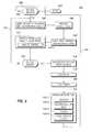
- FIG. 7is a block diagram of vehicle location system 60 adapted to be incorporated into a portable electronic device, such as keyfob 20 shown in FIGS. 1-6 .
- System 60comprises battery 62 for supplying electrical power via power bus 63 to various elements 64 - 78 of system 60 .
- the term “battery”is intended to include any sort of portable electrical energy source, as for example and not intended to be limiting, chemical cells, fuel cells, storage capacitors, solar cells, thermoelectric generators, mechanical generators, nuclear powered cells, and combinations thereof.
- Battery 62may include a power conservation capability (not shown) that disconnects various elements of system 60 when not in use. This is desirable but not essential.
- System 60comprises memory 64 in which resides the software for operating system 60 as well as data downloaded from the vehicle and/or local beacons or satellites, and other data generated within system 60 .
- Memory 64desirably has non-volatile and volatile portions for long term and transient storage of information and data.
- System 60further comprises: keyfob (“FOB”) controller 66 that manages the operation of system 60 ; optional network wireless interface 68 with antenna 69 for communicating with an external network as for example and not intended to be limiting, a network of local nodes; vehicle interface 70 (with antenna 71 when interface 70 is a wireless interface) for communicating with the related system (see FIG.
- FOBkeyfob
- DRdead reckoning
- motion detector 72 - 1 and electronic compass 72 - 2for determining the current location of the keyfob based on a known starting point (e.g., the vehicle) and movement tracking using the motion detector and compass
- GPS navigation system 74with antenna 75 adapted to receive signals from various GPS satellites from which the current position of the keyfob can also be determined
- cell phone interface 76with antenna 73 adapted to utilize available local cell-phone sites for determining the position of the keyfob
- camera 77analogous to camera 41 of FIG.
- user input-output (I/O) interface 78comprising, for example, one or more displays 78 - 1 analogous to display 42 of FIGS. 1-5 , keypad or other user activated input devices 78 - 2 , for example, analogous to buttons 24 - 40 of keypad 20 of FIGS. 1-5 , and annunciator 78 - 3 .
- Annunciator 78 - 3may include both audible and/or visual indicators (e.g., a loudspeaker, buzzer, one or more flashing lights such as in light bar 45 , etc.).
- Elements 64 - 78are coupled via bus 79 .
- System 60is illustrated as using serial bus 79 for coupling elements 64 - 78 that exchange, send or receive information, but persons of skill in the art will understand that the invention is not limited merely to systems employing a serial bus and that the various elements 64 - 78 may be coupled in other ways, as for example and not intended to be limiting, by parallel connections to fob controller 66 or a combination of serial and parallel connections.
- Antennas 69 , 71 , 73 , 75may each be single antennas or a plurality of antennas or an array of distributed antennas, depending upon the vehicle and desired antenna configuration.
- User interface 78 of FIG. 7may comprise any indication means suitable for providing a user with information useful in locating a parked vehicle.
- Interface 78may be, for example, a sound generator such as annunciator 59 , 78 - 3 or visual signal generator 78 - 1 (e.g., a display, such as display 42 shown in FIG. 1 ) and including light bar 45 .
- vehicle interface 70may comprise any device suitable for receiving data from a vehicle indicative of the vehicle's location including the photographs previously described
- interface 70may comprise a wireless transceiver, such as an RF transceiver having antenna 71 adapted to operate at a desired frequency; e.g., Frequencies at or around 315 MHz and 434 MHz are commonly used.
- interface 70may be a wired interface wherein keyfob 20 plugs into a docking station in the vehicle.
- Network wireless interface 68 with antenna 69is configured to receive signals broadcast by nearby wireless network nodes (e.g., local beacons for known location), and to provide related signals to controller 66 .
- controller 66 and network interface 68may be configured in accordance with common compatibility standards for wireless local area networks (e.g., Wi-Fi standards) or for personal area networks (e.g., Bluetooth standards).
- controller 66 and network interface 68may be configured in accordance with low data transmission rate networks (e.g., IEEE 802.15.4, such as a Zigbee network).
- Such low data rate standardshave a data transmission rate slower than that of Wi-Fi or Bluetooth standards (e.g., 250 Kbps at 2.4 GHz), but consume relatively little power and thus may help prolong the life of battery 62 .
- adapting controller 66 and network wireless interface 68 to operate at low data transmission rate standardsmay be especially desirable in embodiments wherein battery 62 is not adapted to being frequently recharged.
- dead reckoning (DR) navigation system 72may include motion detector 72 - 1 .
- Motion detector 72 - 1may comprise any movement-sensitive device.
- motion detector 72 - 1may comprise a circular spring mounted concentric to a pin or wire that passes freely through the center of the circular spring.
- the springdeflects and touches the pin or wire to complete an electrical circuit.
- the surrounding springreturns to its quiescent state wherein the pin or wire is not contacted.
- Such motion detectorsare well-known in the art and desirable for use in conjunction with subsystem 60 due to their modest power requirements.
- DR navigation system 72may utilize motion detector 72 - 1 as a pedometer; that is, DR navigation system 72 may utilize motion detector to measure the number of steps taken by a user.
- DR navigation system 72usefully further employs a compass, such as electronic compass 72 - 2 .
- controller 66may estimate the location of keyfob 20 relative to a reference point such as the vehicle location, in the well-known manner.
- vehicle location system 60may include a conventional GPS navigation system 74 with antenna 75 .
- GPS navigation system 74may be utilized to determine the location of keyfob 20 .
- subsystem 60may determine its location by reference to node location data provided by one or more wireless network nodes as described above.
- Elements 72 , 74 , 76are collectively referred to as tracking system 81 and it should be understood that tracking system 81 can include any combination or subset of elements 72 , 74 , 76 .
- FIG. 8is a block diagram of vehicle mounted electronics system 80 adapted to interface with portable vehicle location system 60 of FIG. 7 of keyfobs 20 of FIGS. 1-6 .
- System 80comprises battery or other energy source 82 which is coupled to the various elements of system 80 via power bus 83 .
- System 80comprises memory 84 in which resides the software for operating system 80 as well as data to be downloaded to system 60 of keyfobs 20 of FIGS. 1-6 .
- Memory 84desirably has non-volatile and volatile portions for long term and transient storage of information and data.
- System 80further comprises: body controller 86 which manages the operation of system 80 as well as other functions within the vehicle normally referred to as the body electronics; optional network wireless interface 88 with antenna 89 for communicating with an external network as for example and not intended to be limiting, a network of local nodes including security cameras and photographic satellites; keyfob interface 90 (with antenna 91 in the case of a wireless interface) for communicating with related system 60 located in keyfob 20 and by which location information, map information, photos, etc., may be downloaded from the vehicle to the keyfob; navigation system 92 incorporating for example a GPS navigation receiver with antenna 93 (or any other form of position determining devices) adapted to receive signals from various GPS satellites from which the current position of the vehicle can be determined for subsequent transmission to the keyfob via interface 90 ; one or more cameras 94 for obtaining views of the vehicle environment, as for example, ahead, to the sides, to the rear of the vehicle, etc.; and optional cell phone interface 96 adapted to utilize available local cell-phone sites for determining
- Cell phone interface 96may include antenna 97 or may merely couple to a separate cell phone system elsewhere in the vehicle. Either arrangement is useful.
- Navigation system 92may also include a dead reckoning (DR) navigation system that operates in combination with a GPS receive to fill in gaps in GPS coverage or operates independently thereof, according to the desires of the system designer.
- Bus 97generally extends to other vehicle sub-systems (not shown) so that controller 86 can, in response to commands from keyfob system 60 , lock or unlock the vehicle, start the engine, unlock the trunk, report on the status of various vehicle sub-systems, and so forth.
- the elements illustrated in system 80are generally those that are useful for interaction with system 60 of FIG. 5 and keyfob 20 of FIGS.
- Antennas 89 , 91 , 93 , 97may each be single antennas or a plurality of antennas or an array of distributed antennas, depending upon the vehicle and desired antenna configuration.
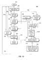
- FIG. 9is a flowchart illustrating exemplary process 100 utilized by vehicle portion 80 of FIG. 8 of the vehicle location system, to provide location and/or photo information to keyfob 20 of FIGS. 1-6 and 7 .
- Process 100begins with START 102 , which may occur when the ignition is turned ON.
- Initial query 104is provided to determine if the vehicle is moving. If the outcome of query 104 is NO (abbreviated as “N”) then method 100 returns to START 102 as shown by pathway 105 . If the outcome of query 104 is YES (abbreviated as “Y”), then method 100 proceeds to MONITOR VEHICLE LOCATION AND LOCATION DATA QUALITY step 106 and subsequent steps.
- step 106data is collected regarding the vehicle location and the accuracy and completeness of the collected vehicle location information, for example and not intended to be limiting, the number of GPS satellites in use by the location monitoring system as the vehicle is parking, satellite signal strength, a list or a summary or of the local beacons encountered, an estimate of the uncertainty of the location information (e.g., horizontal information is accurate to +/ ⁇ 20 meters, altitude information is accurate to +/ ⁇ 1 meter, etc.).
- the quality of the location datawill depend upon the number of satellites and/or local nodes that can be seen by vehicle navigation system 92 (see FIG. 8 ) and the signal to noise ratios of the received signals.
- step 106method 100 desirably but not essentially proceeds to MONITOR VEHICLE SPEED step 108 wherein information on the current vehicle speed (S) is desirably captured.
- the vehicle speed S information obtained in step 108is desirably but not essentially used in step 110 to adjust the interval at which vehicle cameras 94 (see FIG. 8 ) snap photos of the vehicle environment. For example, if the speed S is at or above magnitude S1 (e.g., about 5 miles per hour (MPH)), the photo interval ⁇ is adjusted so that in PHOTO CAPTURE step 112 , photos of the environment around the vehicle are taken about once every ⁇ 1 seconds (e.g., ⁇ 1 ⁇ 5 seconds).
- S1e.g., about 5 miles per hour (MPH)
- the photo intervalis reduced to interval ⁇ 2 ⁇ 1 wherein, for example, the photos are taken once every ⁇ 2 seconds (e.g., ⁇ 2 ⁇ 1 second). Larger or smaller values of ⁇ 1 and ⁇ 2 can also be used. Having ⁇ 2 ⁇ 1 has the advantage of providing more photographs of the vehicle surroundings as it slows and parks.
- cameras 94(see FIG. 8 ) photograph the vehicle environment (e.g., ahead, to the sides, behind, etc.). This process occurs while the vehicle is still moving and as the vehicle slows and after it stops.
- Method 100proceeds to VEHICLE PARKED? query 114 or first to ANALYSE PHOTOS step 112 - 1 and then to query 114 .
- step 112 - 1the photos taken in step 112 are optionally analyzed, for example using pattern recognition techniques, to extract, for example, and not intended to be limiting, alpha-numeric information such as name(s) of the parking structure or building where the vehicle has entered, parking slot identifiers where the vehicle is parked, and other images of interest for location identification purposes. This is desirable but not essential.
- Step 112 - 1may be performed any time prior to step 122 .
- the photos obtained in step 112are taken using cameras 94 of FIG. 8 . Operation of cameras 94 is controlled by body controller 86 and the photos captured in step 112 and analyzed in step 112 - 1 are stored in memory 84 of FIG. 8 .
- VEHICLE PARKED? query 114it is determined whether or not the vehicle has come to a stop and, optionally, the transmission placed in “park.” If the outcome of query 114 is NO, then, as shown by path 115 , method 100 returns to MONITOR VEHICLE LOCATION AND LOCATION DATA QUALITY step 106 . If the outcome of query 114 is YES, then method 100 advances to ACQUIRE PHOTOS FROM OTHER SOURCES step 116 , wherein photos (if available) are acquired from off-board databases via a wireless data connection (e.g., interface 88 of FIG. 8 ) or from onboard devices in the vehicle such as a laptop computer or personal digital assistant or cellular phone.
- a wireless data connectione.g., interface 88 of FIG. 8
- Method 100then advances to TIME DELAY step 118 and STOP PHOTOS step 120 wherein taking of further photos in step 112 is halted after the predetermined time delay of step 116 sufficient to insure, depending upon the photo interval then in use, that photos from the as parked vehicle are included in the photos captured and stored in step 112 .
- step 120the photos captured and stored in steps 112 and 116 (optionally analyzed in step 112 - 1 if included), are then downloaded to keyfob 20 .
- Download step 122includes one or more of (i) sub-step 122 - 1 wherein vehicle location information is downloaded, (ii) sub-step 122 - 2 wherein location quality data is downloaded (e.g., how reliable is the location data), (iii) sub-step 122 - 3 wherein the above-described photos are downloaded, and (iv) sub-step 122 - 4 where the results of photo analysis step 112 - 1 are downloaded. Following download step 122 , method 100 returns to START 102 as shown by path 123 .
- Method 100insures that photo information concerning the vehicle environment will be downloaded to keyfob 20 under any circumstances independent of whether reliable location information is or is not available, and that if reliable location information is available the location information, location quality information and photo information will be downloaded to keyfob 20 .
- the present inventionprovides for multimode operation. Downloading location quality information is desirable but not essential.
- FIG. 10is a flowchart illustrating exemplary process 200 utilized by system 60 (see FIG. 7 ) of keyfob 20 (see FIGS. 1-6 ) of the vehicle location system, to receive location, location quality and/or photo information from the vehicle and further process it and present RETURN-TO-VEHICLE (RTV) information when requested by the user.
- Method 200begins with START 202 and initial RECEIVE DOWNLOAD step 203 , wherein vehicle location, location quality and/or photo information is transferred from vehicle location subsystem 80 to subsystem 60 in keyfob 20 using interface 90 of vehicle subsystem 80 and interface 70 of keyfob subsystem 60 .
- Query 204is executed to confirm that the download is complete. If the outcome of query 204 is NO, then method 200 returns to START 202 as indicated by path 205 and loops until the download is complete. In an alternate embodiment, path 207 is used to check whether a local photograph taken by optional camera 41 , 77 of keyfob 20 is available.
- method 200proceeds to query 206 wherein it is determined whether or not the download includes vehicle location information, as from step 122 - 1 of FIG. 9 . If the outcome of query 206 is YES then method 200 proceeds to ENTER LOCATION MODE step 208 , wherein keyfob subsystem 60 attempts to develop RETURN TO VEHICLE (RTV) information based on using the now known vehicle location as a starting point and employing tracking systems 81 of FIG. 7 to provide updated keyfob locations as the keyfob moves away from the vehicle.
- RTVRETURN TO VEHICLE
- Query 210is provided to determine whether or not such location tracking capability (e.g., tracking system 81 ) within keyfob 20 is active, that is, able to provide further location information about the keyfob as it moves. If the outcome of query 210 is YES, then in step 212 , the current keyfob location relative to the vehicle is updated using the output of one or more of keyfob tracking system 81 . Method 200 then can proceed according to several embodiments as indicated by paths 212 A, 212 B. According to path 212 A, method 200 proceeds to step 213 wherein the overall location quality is assessed.
- location tracking capabilitye.g., tracking system 81
- the quality of the location information derived from step 212depends upon both the quality of the location information downloaded from the vehicle and the quality of the location tracking (e.g., using tracking system 81 ) performed by the keyfob itself.
- method 200proceeds from step 212 via step 213 as shown by paths 212 A, 213 A or directly from step 212 to step 214 as shown by path 212 B.
- query 214it is determined whether or not a RETURN-TO-VEHICLE (RTV) request has been generated, e.g., by the user activating one or the other of buttons 23 and/or scroll wheel 43 as has been previously described. If the outcome of query 214 is NO, then method 200 returns to query 210 to determine whether the fob location tracking capability is still active.
- the loop 210 , 212 , ( 213 ), 214repeats as long as the fob location tracking capability is active, thereby continually updating the keyfob location information relative to the vehicle location. While step 213 is illustrated as occurring prior to step 214 , this is not essential. Step 213 may be executed anytime prior to step 224 .
- method 200proceeds to query 216 as shown by path 211 .
- query 216it is determined whether or not vehicle environment photos have been received from the vehicle, as via download steps 122 - 3 , 122 - 4 of FIG. 9 . If the outcome of query 216 is NO, then method 200 advances to query 218 wherein it is determined whether or not camera 41 , 77 of keyfob subsystem 60 was used to take a photo related to the parked vehicle location and store it in memory 64 . If the outcome of query 218 is NO, indicating that no photos are available either from vehicle subsystem 80 or from fob subsystem 60 and that no keyfob location information relative to the vehicle is available, then method 200 returns to START 202 as shown by path 219 .
- the method 200advances to ENTER PHOTO MODE step 220 , wherein keyfob subsystem 60 will make use of such photo information to assist the user in returning to the vehicle.
- This photo informationas for example but not intended to be limiting, from a photo obtained by keyfob camera 41 , 77 , is desirably but not essentially analyzed in optional PROCESS PHOTOS step 222 to highlight features of the photo(s) that are particularly useful in guiding the user back to the vehicle.
- subsystem 60When the user enters a RETURN-TO-VEHICLE (RTV) request, that is, when the outcome of query 224 is YES, then subsystem 60 presents the RETURN-TO-VEHICLE (RTV) information to the user in step 224 . If the download included vehicle location information and one or more of keyfob location tracking elements 72 , 74 , 76 of tracking system 81 are active, then method 200 (e.g. via path 240 ) presents this location information (and optionally location quality information), as for example is shown in FIGS. 1-3 .
- method 200(e.g., via path 250 ) will present the available photo information, as for example is shown in FIG. 4 . If location (location quality) and photo are available, then the combination can be presented as illustrated for example in FIG. 5 . In either case, useful information is provided to the user to assist him or her in returning to the vehicle. If the vehicle and keyfob environments are such that both location information and photos are available to the keyfob, then both are presented, as shown for example in FIG. 5 .
- the invented arrangement and methodis a multi-mode capable system and method, wherein the system and method automatically adapt to variations in the availability of, for example, GPS signals, and/or local beacon signals, and/or cell phone signals and/or dead reckoning capability and/or images to still provide assistance to the user in returning to his or her vehicle by means of timely stored photos from the location of the parked vehicle.
- Thisis a new and very useful capability.
- the results of this multimode approachare presented to the user on screen 42 of keyfob 20 or by use of annunciator 59 or other output means well known in the art.
- PRESENT RTV INFORMATION TO THE USER step 224method 200 returned to start 202 as shown by path 225 .
- a multi-mode parked vehicle location system and methodmay guide a user back to his or her vehicle. While able to use satellite signals or local beacon signals or cell phone signals if available, even in the absence of such signals, a photo capture feature and method is automatically or manually provided that makes RETURN-TO-VEHICLE (RTV) information available to the user.
- RTVRETURN-TO-VEHICLE
- FIG. 11is a flowchart illustrating exemplary method 300 analogous to that of FIG. 10 , but according to additional embodiments of the invention.
- Method 300provides two pathways to providing return-to-vehicle (RTV) information to the user, path 340 where positional information provided by the vehicle and tracking information developed within the fob is used to provide location information in response to a RTV information request, and path 350 where photo information developed within the vehicle and/or the keyfob is used to provide RTV information in response to a RTV information request, or a combination of paths 340 , 350 wherein both kinds of information are provided depending upon the nature of the user's RTV information request.
- RTVreturn-to-vehicle
- Method 300begins with START 302 and initial step 304 wherein a download such as has been discussed in connection with FIG. 9 is received from the vehicle, for example, via interface 70 of FIG. 7 and interface 90 of FIG. 8 .
- query 306it is determined whether the download of step 304 contains location information (and desirably also quality information). If the outcome of query 306 is NO, then method 300 loops back to START 302 as shown by path 307 .
- method 300advances to ENTER LOCATION MODE step 308 and query 310 wherein the location and quality of the download information is examined to determine whether the vehicle location information is adequate, that is, sufficiently accurate for further processing in keyfob 20 to give a location based output to the user. If the outcome of query 310 is NO, indicating that the quality of the vehicle location information received from the vehicle download, is inadequate, them method 300 proceeds to PHOTO DOWNLOAD RECEIVED query 320 as shown by path 311 , and location information path 340 (as opposed to photo information path 350 ) is abandoned.
- method 300proceeds to query 312 wherein it is determined whether or not one or more of the navigation or position locating elements 72 , 74 , and/or 76 (collectively tracking system 81 of FIG. 7 ) internal to keyfob 20 is active so as to be able to track the location of keyfob 20 relative to the vehicle position. If the outcome of query 312 is NO, indicating that the keyfob tracking system 81 is inoperative for whatever reason, then method 300 proceeds to PHOTO DOWNLOAD RECEIVED query 320 as shown by path 313 , with the same result as by path 311 .
- method 300proceeds to PHOTO DOWNLOAD RECEIVED query 320 wherein it is determined whether the vehicle has transmitted vehicle environment photo information to keyfob 20 . If the outcome of query 320 is NO, then method 300 proceeds to LOCAL PHOTO query 326 wherein it is determined whether or not a local photo from the vehicle location has been taken by the user. If the outcome of query 326 is NO, indicating that no photo information either local or from the vehicle is available, then method 300 returns to start 302 s illustrated by path 327 .
- method 300proceeds to ENTER PHOTO MODE step 322 and optional PROCESS PHOTOS step 324 wherein generally the same type of processing described in connection with step 112 - 1 of FIG. 9 and/or step 222 of FIG. 10 is optionally performed. Method 300 then proceeds to RTV INFO REQUEST query 316 , the same destination that could be reached via path 340 from UP-DATE step 314 .
- Query 316determines whether or not the user has asked for information on how to return to his or her vehicle. If the outcome of query 316 is NO, then method 300 returns to step 324 for photo information and step 315 for location information and method 300 cycles so as to maintain updated information until the outcome of query 316 is YES. When the outcome of query 316 is YES, then method 300 advances through queries 326 , 330 , 334 in any order, to determine what type of RTV information has been requested by the user. If the user has requested both location and photo information (query 326 ), then in step 328 photo and location information such as is illustrated for example in FIG. 5 , is presented to the user on display 42 and/or annunciator 59 or a combination thereof.
- location quality informationis available, it is desirably included. If the user has requested only location information (query 330 ), then in step 332 only location (and location quality) information is presented such as is illustrated for example in FIGS. 1-3 to the user on display 42 or annunciator 59 , light bar 45 and/or a combination thereof. If the user has requested only photo information (query 334 ), then in step 336 only photo information such as is illustrated for example in FIG. 4 , is presented to the user on display 42 and/or annunciator 59 or a combination thereof. Following any of presentation steps 328 , 332 , 336 method 300 returns to START 302 as shown by path 337 .
- a multi-mode parked vehicle location system and methodmay guide a user back to his or her vehicle. While able to use satellite signals or local beacon signals or cell phone signals if available, even in the absence of such signals, a photo capture feature and method is automatically or manually provided that makes RETURN-TO-VEHICLE (RTV) information available to the user.
- RTVRETURN-TO-VEHICLE
Landscapes
- Engineering & Computer Science (AREA)
- Radar, Positioning & Navigation (AREA)
- Remote Sensing (AREA)
- Physics & Mathematics (AREA)
- General Physics & Mathematics (AREA)
- Automation & Control Theory (AREA)
- Multimedia (AREA)
- Traffic Control Systems (AREA)
Abstract
Description
Claims (20)
Priority Applications (1)
| Application Number | Priority Date | Filing Date | Title |
|---|---|---|---|
| US11/845,836US7847709B2 (en) | 2007-08-28 | 2007-08-28 | Multimode vehicle location device and method |
Applications Claiming Priority (1)
| Application Number | Priority Date | Filing Date | Title |
|---|---|---|---|
| US11/845,836US7847709B2 (en) | 2007-08-28 | 2007-08-28 | Multimode vehicle location device and method |
Publications (2)
| Publication Number | Publication Date |
|---|---|
| US20090058685A1 US20090058685A1 (en) | 2009-03-05 |
| US7847709B2true US7847709B2 (en) | 2010-12-07 |
Family
ID=40406611
Family Applications (1)
| Application Number | Title | Priority Date | Filing Date |
|---|---|---|---|
| US11/845,836Active2028-10-06US7847709B2 (en) | 2007-08-28 | 2007-08-28 | Multimode vehicle location device and method |
Country Status (1)
| Country | Link |
|---|---|
| US (1) | US7847709B2 (en) |
Cited By (62)
| Publication number | Priority date | Publication date | Assignee | Title |
|---|---|---|---|---|
| US20090012708A1 (en)* | 2007-01-05 | 2009-01-08 | Jui-Chien Wu | Personal navigation devices and related methods |
| US20090061895A1 (en)* | 2007-09-05 | 2009-03-05 | Sony Ericsson Mobile Communications Ab | Mobile terminals and operating methods that share location information with location-aware devices |
| US20100103036A1 (en)* | 2008-10-28 | 2010-04-29 | Audiovox Corporation | Portable transceiver with vehicle security control and locate features |
| US20110022301A1 (en)* | 2009-07-27 | 2011-01-27 | Htc Corporation | Method, mobile device and recording medium for recording parking information |
| US20110140927A1 (en)* | 2009-12-14 | 2011-06-16 | Kevin Lawrence Lee | Method and apparatus for avoiding parking violations |
| US20120235835A1 (en)* | 2011-03-18 | 2012-09-20 | Jahn Deborah M | Musical Key Fob Vehicle Locator |
| WO2012095754A3 (en)* | 2011-01-14 | 2012-11-15 | Anagog Ltd. | Predicting that a parking space is about to be vacated |
| USD695639S1 (en) | 2013-05-31 | 2013-12-17 | Lynn Pate | Vehicle locating device |
| US20140005859A1 (en)* | 2012-06-30 | 2014-01-02 | Lonny Baskin | Remote management and control of vehicular functions via multiple networks |
| US20140256258A1 (en)* | 2013-03-06 | 2014-09-11 | Joan Deluca | Parked vehicle locating smartphone application |
| US9019129B2 (en)* | 2013-02-21 | 2015-04-28 | Apple Inc. | Vehicle location in weak location signal scenarios |
| US9082307B2 (en) | 2013-02-19 | 2015-07-14 | King Fahd University Of Petroleum And Minerals | Circular antenna array for vehicular direction finding |
| US9080878B2 (en) | 2013-02-21 | 2015-07-14 | Apple Inc. | Automatic identification of vehicle location |
| US9264862B2 (en) | 2013-08-15 | 2016-02-16 | Apple Inc. | Determining exit from a vehicle |
| US9892610B1 (en)* | 2015-06-04 | 2018-02-13 | Awearable Apparel Inc. | Systems, methods, and devices for locating items, people, and/or animals |
| US9933450B2 (en) | 2011-01-24 | 2018-04-03 | Anagog Ltd. | Mobility determination |
| US10121374B2 (en) | 2016-06-10 | 2018-11-06 | Apple Inc. | Parking event detection and location estimation |
| US20190057599A1 (en)* | 2016-02-27 | 2019-02-21 | Audi Ag | Method for finding a parked vehicle in a parking structure, and parking structure |
| US20190077371A1 (en)* | 2017-03-20 | 2019-03-14 | Daphne Gaither | GPS-Enabled Key Fob with Voice Capability |
| US10234868B2 (en) | 2017-06-16 | 2019-03-19 | Ford Global Technologies, Llc | Mobile device initiation of vehicle remote-parking |
| US10281921B2 (en) | 2017-10-02 | 2019-05-07 | Ford Global Technologies, Llc | Autonomous parking of vehicles in perpendicular parking spots |
| US10336320B2 (en) | 2017-11-22 | 2019-07-02 | Ford Global Technologies, Llc | Monitoring of communication for vehicle remote park-assist |
| US10369988B2 (en) | 2017-01-13 | 2019-08-06 | Ford Global Technologies, Llc | Autonomous parking of vehicles inperpendicular parking spots |
| US10384605B1 (en) | 2018-09-04 | 2019-08-20 | Ford Global Technologies, Llc | Methods and apparatus to facilitate pedestrian detection during remote-controlled maneuvers |
| US10493981B2 (en) | 2018-04-09 | 2019-12-03 | Ford Global Technologies, Llc | Input signal management for vehicle park-assist |
| US10507868B2 (en) | 2018-02-22 | 2019-12-17 | Ford Global Technologies, Llc | Tire pressure monitoring for vehicle park-assist |
| US10529233B1 (en) | 2018-09-24 | 2020-01-07 | Ford Global Technologies Llc | Vehicle and method for detecting a parking space via a drone |
| US10553113B2 (en) | 2018-06-18 | 2020-02-04 | Skip Transport, Inc. | Method and system for vehicle location |
| US10580304B2 (en) | 2017-10-02 | 2020-03-03 | Ford Global Technologies, Llc | Accelerometer-based external sound monitoring for voice controlled autonomous parking |
| US10578676B2 (en) | 2017-11-28 | 2020-03-03 | Ford Global Technologies, Llc | Vehicle monitoring of mobile device state-of-charge |
| US10583830B2 (en) | 2018-01-02 | 2020-03-10 | Ford Global Technologies, Llc | Mobile device tethering for a remote parking assist system of a vehicle |
| US10585430B2 (en) | 2017-06-16 | 2020-03-10 | Ford Global Technologies, Llc | Remote park-assist authentication for vehicles |
| US10585431B2 (en) | 2018-01-02 | 2020-03-10 | Ford Global Technologies, Llc | Mobile device tethering for a remote parking assist system of a vehicle |
| US10628687B1 (en) | 2018-10-12 | 2020-04-21 | Ford Global Technologies, Llc | Parking spot identification for vehicle park-assist |
| US10627811B2 (en) | 2017-11-07 | 2020-04-21 | Ford Global Technologies, Llc | Audio alerts for remote park-assist tethering |
| US10684627B2 (en) | 2018-02-06 | 2020-06-16 | Ford Global Technologies, Llc | Accelerometer-based external sound monitoring for position aware autonomous parking |
| US10683034B2 (en) | 2017-06-06 | 2020-06-16 | Ford Global Technologies, Llc | Vehicle remote parking systems and methods |
| US10683004B2 (en) | 2018-04-09 | 2020-06-16 | Ford Global Technologies, Llc | Input signal management for vehicle park-assist |
| US10684773B2 (en) | 2018-01-03 | 2020-06-16 | Ford Global Technologies, Llc | Mobile device interface for trailer backup-assist |
| US10688918B2 (en) | 2018-01-02 | 2020-06-23 | Ford Global Technologies, Llc | Mobile device tethering for a remote parking assist system of a vehicle |
| US10717432B2 (en) | 2018-09-13 | 2020-07-21 | Ford Global Technologies, Llc | Park-assist based on vehicle door open positions |
| US10732622B2 (en) | 2018-04-05 | 2020-08-04 | Ford Global Technologies, Llc | Advanced user interaction features for remote park assist |
| US10737690B2 (en) | 2018-01-02 | 2020-08-11 | Ford Global Technologies, Llc | Mobile device tethering for a remote parking assist system of a vehicle |
| US10747218B2 (en) | 2018-01-12 | 2020-08-18 | Ford Global Technologies, Llc | Mobile device tethering for remote parking assist |
| US10759417B2 (en) | 2018-04-09 | 2020-09-01 | Ford Global Technologies, Llc | Input signal management for vehicle park-assist |
| US10775781B2 (en) | 2017-06-16 | 2020-09-15 | Ford Global Technologies, Llc | Interface verification for vehicle remote park-assist |
| US10793144B2 (en) | 2018-04-09 | 2020-10-06 | Ford Global Technologies, Llc | Vehicle remote park-assist communication counters |
| US10814864B2 (en) | 2018-01-02 | 2020-10-27 | Ford Global Technologies, Llc | Mobile device tethering for a remote parking assist system of a vehicle |
| US10821972B2 (en) | 2018-09-13 | 2020-11-03 | Ford Global Technologies, Llc | Vehicle remote parking assist systems and methods |
| US10908603B2 (en) | 2018-10-08 | 2021-02-02 | Ford Global Technologies, Llc | Methods and apparatus to facilitate remote-controlled maneuvers |
| US10917748B2 (en) | 2018-01-25 | 2021-02-09 | Ford Global Technologies, Llc | Mobile device tethering for vehicle systems based on variable time-of-flight and dead reckoning |
| US10967851B2 (en) | 2018-09-24 | 2021-04-06 | Ford Global Technologies, Llc | Vehicle system and method for setting variable virtual boundary |
| US10974717B2 (en) | 2018-01-02 | 2021-04-13 | Ford Global Technologies, I.LC | Mobile device tethering for a remote parking assist system of a vehicle |
| US11097723B2 (en) | 2018-10-17 | 2021-08-24 | Ford Global Technologies, Llc | User interfaces for vehicle remote park assist |
| US11137754B2 (en) | 2018-10-24 | 2021-10-05 | Ford Global Technologies, Llc | Intermittent delay mitigation for remote vehicle operation |
| US11146759B1 (en)* | 2018-11-13 | 2021-10-12 | JMJ Designs, LLC | Vehicle camera system |
| US11148661B2 (en) | 2018-01-02 | 2021-10-19 | Ford Global Technologies, Llc | Mobile device tethering for a remote parking assist system of a vehicle |
| US11169517B2 (en) | 2019-04-01 | 2021-11-09 | Ford Global Technologies, Llc | Initiation of vehicle remote park-assist with key fob |
| US11188070B2 (en) | 2018-02-19 | 2021-11-30 | Ford Global Technologies, Llc | Mitigating key fob unavailability for remote parking assist systems |
| US11195344B2 (en) | 2019-03-15 | 2021-12-07 | Ford Global Technologies, Llc | High phone BLE or CPU burden detection and notification |
| US11275368B2 (en) | 2019-04-01 | 2022-03-15 | Ford Global Technologies, Llc | Key fobs for vehicle remote park-assist |
| US11789442B2 (en) | 2019-02-07 | 2023-10-17 | Ford Global Technologies, Llc | Anomalous input detection |
Families Citing this family (41)
| Publication number | Priority date | Publication date | Assignee | Title |
|---|---|---|---|---|
| WO2008123262A1 (en)* | 2007-03-26 | 2008-10-16 | Semiconductor Energy Laboratory Co., Ltd. | Individual management system |
| US7847709B2 (en) | 2007-08-28 | 2010-12-07 | Gm Global Technology Operations, Inc. | Multimode vehicle location device and method |
| US20090091477A1 (en)* | 2007-10-08 | 2009-04-09 | Gm Global Technology Operations, Inc. | Vehicle fob with expanded display area |
| US20090098907A1 (en)* | 2007-10-15 | 2009-04-16 | Gm Global Technology Operations, Inc. | Parked Vehicle Location Information Access via a Portable Cellular Communication Device |
| US20090284396A1 (en)* | 2008-05-16 | 2009-11-19 | Mohamed Rafeek | System for locating vehicles in parking lots and method thereof |
| US20100114488A1 (en)* | 2008-10-31 | 2010-05-06 | Temic Automotive Of North America, Inc. | Systems and Methods for Locating a Vehicle |
| US20110001665A1 (en)* | 2009-07-02 | 2011-01-06 | Leap Devices, LLC | Camera Radio Signal Operation Based on Global Positioning |
| CN102656060B (en)* | 2009-12-14 | 2015-12-16 | 大陆汽车有限责任公司 | For the emergency call receiving element of staff |
| DE102010018332A1 (en)* | 2010-04-27 | 2011-10-27 | Gm Global Technology Operations Llc (N.D.Ges.D. Staates Delaware) | A method for locating a parked vehicle and portable locating device for locating a parked vehicle |
| US8694252B2 (en)* | 2010-06-02 | 2014-04-08 | Mitac International Corp. | Personal navigation device which provides portable electronic map and related navigating method |
| US20120176255A1 (en)* | 2011-01-10 | 2012-07-12 | Deutsche Telekom Ag | Mobile device-based automatic parking location recorder and reminder using on-board diagnostics |
| BR112013018160A2 (en)* | 2011-01-17 | 2018-09-11 | Imetrik Technologies Inc. | computer-implemented method and system for reporting a confidence score for a vehicle equipped with a wireless enabled usage reporting device |
| US9373108B2 (en)* | 2011-01-21 | 2016-06-21 | Paypal, Inc. | Point of sale payment system |
| US20120316774A1 (en)* | 2011-06-09 | 2012-12-13 | Microsoft Corporation | Automatic navigation to a prior known location |
| US9207096B2 (en)* | 2011-06-09 | 2015-12-08 | Blackberry Limited | Map magnifier |
| US8600665B2 (en)* | 2011-06-13 | 2013-12-03 | Dennis Leonard Vander Linde | System and method for aligning a particular passenger with a unique vehicle |
| KR20130050500A (en)* | 2011-11-08 | 2013-05-16 | 한국전자통신연구원 | Method of providing position information and apparatus for the same |
| US9125022B2 (en) | 2011-12-02 | 2015-09-01 | Microsoft Technology Licensing, Llc | Inferring positions with content item matching |
| US20140028477A1 (en)* | 2012-07-24 | 2014-01-30 | Apple Inc. | Vehicle location system |
| US8798926B2 (en)* | 2012-11-14 | 2014-08-05 | Navteq B.V. | Automatic image capture |
| US20150177362A1 (en)* | 2013-03-13 | 2015-06-25 | ACCO Brands Corporation | Proximity tags for vehicles |
| KR101484202B1 (en)* | 2013-03-29 | 2015-01-21 | 현대자동차 주식회사 | Vehicle having gesture detection system |
| JP2014202705A (en)* | 2013-04-09 | 2014-10-27 | パナソニック株式会社 | Electronic key, on-vehicle apparatus, guide apparatus and car finder system |
| US20150039224A1 (en)* | 2013-07-30 | 2015-02-05 | Here Global B.V. | Method and apparatus for detecting and sharing vehicle location |
| DE102013215960A1 (en) | 2013-08-13 | 2015-03-05 | Volkswagen Aktiengesellschaft | Determining a position information of a vehicle |
| US20150077275A1 (en)* | 2013-09-19 | 2015-03-19 | Ford Global Technologies, Llc | Method and Apparatus for Automatic Location Check-In Control in a Vehicle |
| CN105594267B (en)* | 2013-10-31 | 2019-09-24 | 英特尔公司 | The virtual crumbs searched for indoor location road |
| TW201519174A (en)* | 2013-11-14 | 2015-05-16 | Hon Hai Prec Ind Co Ltd | Searching system for position of car and method |
| DE102014013208B3 (en)* | 2014-09-06 | 2016-01-14 | Audi Ag | Method for navigating a user between a first position within a building and a second position |
| DE102014013207A1 (en)* | 2014-09-06 | 2015-08-27 | Audi Ag | A method for navigating a user between a first position within a building area and a second location |
| US9437013B2 (en)* | 2015-04-21 | 2016-09-06 | David Douglas | Simplified real time location-dependent color-coded display (“chloropleth”) system and method |
| US10097973B2 (en) | 2015-05-27 | 2018-10-09 | Apple Inc. | Systems and methods for proactively identifying and surfacing relevant content on a touch-sensitive device |
| US10200824B2 (en)* | 2015-05-27 | 2019-02-05 | Apple Inc. | Systems and methods for proactively identifying and surfacing relevant content on a touch-sensitive device |
| WO2018090226A1 (en)* | 2016-11-16 | 2018-05-24 | 郝磊 | Method, device, and system for vehicle positioning |
| DE102017220246A1 (en) | 2017-11-14 | 2019-05-16 | Audi Ag | Method for preparing a vehicle |
| KR102017802B1 (en)* | 2017-12-21 | 2019-09-03 | 엘지전자 주식회사 | Mobile terminal and method for controlling the same |
| US11023742B2 (en)* | 2018-09-07 | 2021-06-01 | Tusimple, Inc. | Rear-facing perception system for vehicles |
| CN110444039B (en)* | 2019-07-26 | 2021-04-23 | 浙江吉利汽车研究院有限公司 | A parking positioning method, device, system and storage medium |
| DE102019214660A1 (en)* | 2019-09-25 | 2021-03-25 | Volkswagen Aktiengesellschaft | Method and vehicle with a device for locating the vehicle |
| DE102020213060A1 (en) | 2020-10-15 | 2022-04-21 | Volkswagen Aktiengesellschaft | Method and device for providing parking data to a vehicle user |
| US11453338B2 (en)* | 2021-02-11 | 2022-09-27 | Ford Global Technologies, Llc | Selfie button for vehicle cameras with flash |
Citations (36)
| Publication number | Priority date | Publication date | Assignee | Title |
|---|---|---|---|---|
| US5173686A (en) | 1989-12-15 | 1992-12-22 | Clarion Co., Ltd. | Sliding accommodation type liquid crystal display device |
| US5519621A (en) | 1991-01-17 | 1996-05-21 | Highwaymaster Communications, Inc. | Vehicle locating and communicating method and apparatus |
| US5777580A (en) | 1992-11-18 | 1998-07-07 | Trimble Navigation Limited | Vehicle location system |
| US6340935B1 (en)* | 1999-02-05 | 2002-01-22 | Brett O. Hall | Computerized parking facility management system |
| US6392592B1 (en)* | 1999-09-30 | 2002-05-21 | Siemens Automotive Corporation | Hand held car locator |
| US6405125B1 (en) | 2000-09-26 | 2002-06-11 | Mourad Ben Ayed | Parked vehicle locator |
| US6529142B2 (en)* | 2000-07-24 | 2003-03-04 | Shipong Norman Yeh | Parked vehicle location finder |
| US20030144034A1 (en) | 2001-12-12 | 2003-07-31 | Hack Michael G. | Intelligent multi-media display communication system |
| US20030164778A1 (en) | 2002-02-27 | 2003-09-04 | Yamaha Corporation | Vehicle position communication system, vehicle navigation apparatus and portable communications apparatus |
| US6637896B2 (en) | 2001-10-31 | 2003-10-28 | Motorola, Inc. | Compact projection system and associated device |
| US6738712B1 (en) | 2000-06-17 | 2004-05-18 | Mindfunnel.Com, Inc. | Electronic location system |
| US20050096106A1 (en) | 2003-11-03 | 2005-05-05 | Bennetts David J. | Electronic apparatus |
| US6909964B2 (en)* | 2002-07-03 | 2005-06-21 | Delphi Technologies, Inc. | Vehicle locating system |
| US7003318B2 (en) | 2002-09-20 | 2006-02-21 | Hitachi, Ltd. | Mobile phone with camera |
| US20060111835A1 (en) | 2004-11-23 | 2006-05-25 | Texas Instruments Incorporated | Location system for locating a parked vehicle, a method for providing a location of a parked vehicle and a personal wireless device incorporating the system or method |
| US7058433B2 (en) | 2003-11-06 | 2006-06-06 | Sony Ericsson Mobile Communications Ab | Mechanism for ergonomic integration of a digital camera into a mobile phone |
| US20060139155A1 (en)* | 2004-12-14 | 2006-06-29 | Jounghoon Kim | Remote access system for a vehicle |
| US20060234784A1 (en) | 2004-12-21 | 2006-10-19 | Silviu Reinhorn | Collapsible portable display |
| US7145507B2 (en) | 2003-12-16 | 2006-12-05 | Lear Corporation | Vehicle locating system using GPS |
| US20070022445A1 (en) | 2005-07-22 | 2007-01-25 | Marc Arseneau | System and Methods for Enhancing the Experience of Spectators Attending a Live Sporting Event, with User Interface Programming Capability |
| US7195382B1 (en) | 2004-06-30 | 2007-03-27 | Magna Donnelly Mirrors North America, L.L.C. | Vehicle mirror with secondary lighting lens for ground illuminator |
| US7195381B2 (en) | 2001-01-23 | 2007-03-27 | Donnelly Corporation | Vehicle interior LED lighting system |
| US20070126603A1 (en) | 2005-12-06 | 2007-06-07 | Driscoll Shon T | Method and system for locating parked cars |
| US7242321B2 (en)* | 2005-04-27 | 2007-07-10 | Daimlerchrysler Corporation | Key fob with directional vehicle locator |
| US20070184852A1 (en) | 2006-01-17 | 2007-08-09 | Johnson David W | Method and system for location of objects within a specified geographic area |
| US7260473B2 (en) | 2000-06-29 | 2007-08-21 | Nokia Corporation | Method and mobile station for route guidance |
| US20070285401A1 (en) | 2004-11-09 | 2007-12-13 | Sharp Kabushiki Kaisha | Portable Information Terminal |
| US20080167806A1 (en) | 2007-01-05 | 2008-07-10 | Zeetoo, Inc. | System and method for providing local maps using wireless handheld devices |
| US20080172197A1 (en) | 2007-01-11 | 2008-07-17 | Motorola, Inc. | Single laser multi-color projection display with quantum dot screen |
| US20090051832A1 (en) | 2002-09-05 | 2009-02-26 | Philip Banks | Portable image projection device |
| US20090058685A1 (en) | 2007-08-28 | 2009-03-05 | Gm Global Technology Operations, Inc. | Multimode Vehicle Location Device and Method |
| US20090091477A1 (en) | 2007-10-08 | 2009-04-09 | Gm Global Technology Operations, Inc. | Vehicle fob with expanded display area |
| US20090131129A1 (en) | 2004-10-28 | 2009-05-21 | Matsushita Electric Industrial Co., Ltd. | Portable telephone with broadcast receiver |
| US7545259B2 (en)* | 2006-08-28 | 2009-06-09 | Lear Corporation | Vehicle locating using GPS |
| US7558057B1 (en) | 2005-06-06 | 2009-07-07 | Alex Naksen | Personal digital device with adjustable interface |
| US7639237B2 (en) | 2006-03-03 | 2009-12-29 | Perkins Michael T | Roll-out touch screen support system (ROTS3) |
- 2007
- 2007-08-28USUS11/845,836patent/US7847709B2/enactiveActive
Patent Citations (36)
| Publication number | Priority date | Publication date | Assignee | Title |
|---|---|---|---|---|
| US5173686A (en) | 1989-12-15 | 1992-12-22 | Clarion Co., Ltd. | Sliding accommodation type liquid crystal display device |
| US5519621A (en) | 1991-01-17 | 1996-05-21 | Highwaymaster Communications, Inc. | Vehicle locating and communicating method and apparatus |
| US5777580A (en) | 1992-11-18 | 1998-07-07 | Trimble Navigation Limited | Vehicle location system |
| US6340935B1 (en)* | 1999-02-05 | 2002-01-22 | Brett O. Hall | Computerized parking facility management system |
| US6392592B1 (en)* | 1999-09-30 | 2002-05-21 | Siemens Automotive Corporation | Hand held car locator |
| US6738712B1 (en) | 2000-06-17 | 2004-05-18 | Mindfunnel.Com, Inc. | Electronic location system |
| US7260473B2 (en) | 2000-06-29 | 2007-08-21 | Nokia Corporation | Method and mobile station for route guidance |
| US6529142B2 (en)* | 2000-07-24 | 2003-03-04 | Shipong Norman Yeh | Parked vehicle location finder |
| US6405125B1 (en) | 2000-09-26 | 2002-06-11 | Mourad Ben Ayed | Parked vehicle locator |
| US7195381B2 (en) | 2001-01-23 | 2007-03-27 | Donnelly Corporation | Vehicle interior LED lighting system |
| US6637896B2 (en) | 2001-10-31 | 2003-10-28 | Motorola, Inc. | Compact projection system and associated device |
| US20030144034A1 (en) | 2001-12-12 | 2003-07-31 | Hack Michael G. | Intelligent multi-media display communication system |
| US20030164778A1 (en) | 2002-02-27 | 2003-09-04 | Yamaha Corporation | Vehicle position communication system, vehicle navigation apparatus and portable communications apparatus |
| US6909964B2 (en)* | 2002-07-03 | 2005-06-21 | Delphi Technologies, Inc. | Vehicle locating system |
| US20090051832A1 (en) | 2002-09-05 | 2009-02-26 | Philip Banks | Portable image projection device |
| US7003318B2 (en) | 2002-09-20 | 2006-02-21 | Hitachi, Ltd. | Mobile phone with camera |
| US20050096106A1 (en) | 2003-11-03 | 2005-05-05 | Bennetts David J. | Electronic apparatus |
| US7058433B2 (en) | 2003-11-06 | 2006-06-06 | Sony Ericsson Mobile Communications Ab | Mechanism for ergonomic integration of a digital camera into a mobile phone |
| US7145507B2 (en) | 2003-12-16 | 2006-12-05 | Lear Corporation | Vehicle locating system using GPS |
| US7195382B1 (en) | 2004-06-30 | 2007-03-27 | Magna Donnelly Mirrors North America, L.L.C. | Vehicle mirror with secondary lighting lens for ground illuminator |
| US20090131129A1 (en) | 2004-10-28 | 2009-05-21 | Matsushita Electric Industrial Co., Ltd. | Portable telephone with broadcast receiver |
| US20070285401A1 (en) | 2004-11-09 | 2007-12-13 | Sharp Kabushiki Kaisha | Portable Information Terminal |
| US20060111835A1 (en) | 2004-11-23 | 2006-05-25 | Texas Instruments Incorporated | Location system for locating a parked vehicle, a method for providing a location of a parked vehicle and a personal wireless device incorporating the system or method |
| US20060139155A1 (en)* | 2004-12-14 | 2006-06-29 | Jounghoon Kim | Remote access system for a vehicle |
| US20060234784A1 (en) | 2004-12-21 | 2006-10-19 | Silviu Reinhorn | Collapsible portable display |
| US7242321B2 (en)* | 2005-04-27 | 2007-07-10 | Daimlerchrysler Corporation | Key fob with directional vehicle locator |
| US7558057B1 (en) | 2005-06-06 | 2009-07-07 | Alex Naksen | Personal digital device with adjustable interface |
| US20070022445A1 (en) | 2005-07-22 | 2007-01-25 | Marc Arseneau | System and Methods for Enhancing the Experience of Spectators Attending a Live Sporting Event, with User Interface Programming Capability |
| US20070126603A1 (en) | 2005-12-06 | 2007-06-07 | Driscoll Shon T | Method and system for locating parked cars |
| US20070184852A1 (en) | 2006-01-17 | 2007-08-09 | Johnson David W | Method and system for location of objects within a specified geographic area |
| US7639237B2 (en) | 2006-03-03 | 2009-12-29 | Perkins Michael T | Roll-out touch screen support system (ROTS3) |
| US7545259B2 (en)* | 2006-08-28 | 2009-06-09 | Lear Corporation | Vehicle locating using GPS |
| US20080167806A1 (en) | 2007-01-05 | 2008-07-10 | Zeetoo, Inc. | System and method for providing local maps using wireless handheld devices |
| US20080172197A1 (en) | 2007-01-11 | 2008-07-17 | Motorola, Inc. | Single laser multi-color projection display with quantum dot screen |
| US20090058685A1 (en) | 2007-08-28 | 2009-03-05 | Gm Global Technology Operations, Inc. | Multimode Vehicle Location Device and Method |
| US20090091477A1 (en) | 2007-10-08 | 2009-04-09 | Gm Global Technology Operations, Inc. | Vehicle fob with expanded display area |
Non-Patent Citations (6)
| Title |
|---|
| Bee, A. W., Non-final Office Action issued in U.S. Appl. No. 11/868,821, mailed on Oct. 2, 2009. |
| Office Action dated Jul. 22, 2010, issued in U.S. Appl. No. 11/872,075. |
| Response to Office Action dated Oct. 18, 2010, filed in U.S. Appl. No. 11/872,075. |
| Shipley, C. "Digismart-Miniature Projection Technology," www.digislide.com.au/consumer/digismart.htm, 2006. |
| Shipley, C. "Digismart—Miniature Projection Technology," www.digislide.com.au/consumer/digismart.htm, 2006. |
| Swarthout, B., Office Action mailed Jan. 29, 2010, for U.S. Appl. No. 11/868,821. |
Cited By (74)
| Publication number | Priority date | Publication date | Assignee | Title |
|---|---|---|---|---|
| US20090012708A1 (en)* | 2007-01-05 | 2009-01-08 | Jui-Chien Wu | Personal navigation devices and related methods |
| US20090061895A1 (en)* | 2007-09-05 | 2009-03-05 | Sony Ericsson Mobile Communications Ab | Mobile terminals and operating methods that share location information with location-aware devices |
| US20100103036A1 (en)* | 2008-10-28 | 2010-04-29 | Audiovox Corporation | Portable transceiver with vehicle security control and locate features |
| US20150283976A1 (en)* | 2008-10-28 | 2015-10-08 | Voxx International Corporation | Portable transceiver with vehicle security control and locate features |
| US9063833B2 (en) | 2008-10-28 | 2015-06-23 | Voxx International Corporation | Portable transceiver with vehicle security control and locate features |
| US8380430B2 (en)* | 2008-10-28 | 2013-02-19 | Audiovox Corporation | Portable transceiver with vehicle security control and locate features |
| US20110022301A1 (en)* | 2009-07-27 | 2011-01-27 | Htc Corporation | Method, mobile device and recording medium for recording parking information |
| US20110140927A1 (en)* | 2009-12-14 | 2011-06-16 | Kevin Lawrence Lee | Method and apparatus for avoiding parking violations |
| WO2012095754A3 (en)* | 2011-01-14 | 2012-11-15 | Anagog Ltd. | Predicting that a parking space is about to be vacated |
| US10152889B2 (en)* | 2011-01-14 | 2018-12-11 | Anagog Ltd. | Predicting that a parking space is about to be vacated |
| US9933450B2 (en) | 2011-01-24 | 2018-04-03 | Anagog Ltd. | Mobility determination |
| US8542131B2 (en)* | 2011-03-18 | 2013-09-24 | Deborah Michelle Jahn | Musical key fob vehicle locator |
| US20120235835A1 (en)* | 2011-03-18 | 2012-09-20 | Jahn Deborah M | Musical Key Fob Vehicle Locator |
| US20140005859A1 (en)* | 2012-06-30 | 2014-01-02 | Lonny Baskin | Remote management and control of vehicular functions via multiple networks |
| US9031712B2 (en)* | 2012-06-30 | 2015-05-12 | Intel Corporation | Remote management and control of vehicular functions via multiple networks |
| US9082307B2 (en) | 2013-02-19 | 2015-07-14 | King Fahd University Of Petroleum And Minerals | Circular antenna array for vehicular direction finding |
| US9080878B2 (en) | 2013-02-21 | 2015-07-14 | Apple Inc. | Automatic identification of vehicle location |
| US9019129B2 (en)* | 2013-02-21 | 2015-04-28 | Apple Inc. | Vehicle location in weak location signal scenarios |
| US20140256258A1 (en)* | 2013-03-06 | 2014-09-11 | Joan Deluca | Parked vehicle locating smartphone application |
| USD695639S1 (en) | 2013-05-31 | 2013-12-17 | Lynn Pate | Vehicle locating device |
| US10182316B1 (en) | 2013-08-15 | 2019-01-15 | Apple Inc. | Determining location of parked vehicle |
| US9712977B2 (en) | 2013-08-15 | 2017-07-18 | Apple Inc. | Determining exit from a vehicle |
| US9264862B2 (en) | 2013-08-15 | 2016-02-16 | Apple Inc. | Determining exit from a vehicle |
| US10460584B1 (en) | 2015-06-04 | 2019-10-29 | Lynq Technologies, Inc. | Systems, methods, and devices for locating items, people, and/or animals |
| US11145179B1 (en) | 2015-06-04 | 2021-10-12 | Lynq Technologies, Inc. | Systems, methods, and devices for locating items, people, and/or animals |
| US9892610B1 (en)* | 2015-06-04 | 2018-02-13 | Awearable Apparel Inc. | Systems, methods, and devices for locating items, people, and/or animals |
| US11704989B1 (en) | 2015-06-04 | 2023-07-18 | Lynq Technologies, Inc. | Systems, methods, and devices for locating items, people, and/or animals |
| US20190057599A1 (en)* | 2016-02-27 | 2019-02-21 | Audi Ag | Method for finding a parked vehicle in a parking structure, and parking structure |
| US10467894B2 (en)* | 2016-02-27 | 2019-11-05 | Audi Ag | Method for finding a parked vehicle in a parking structure, and parking structure |
| US10121374B2 (en) | 2016-06-10 | 2018-11-06 | Apple Inc. | Parking event detection and location estimation |
| US10369988B2 (en) | 2017-01-13 | 2019-08-06 | Ford Global Technologies, Llc | Autonomous parking of vehicles inperpendicular parking spots |
| US20190077371A1 (en)* | 2017-03-20 | 2019-03-14 | Daphne Gaither | GPS-Enabled Key Fob with Voice Capability |
| US10683034B2 (en) | 2017-06-06 | 2020-06-16 | Ford Global Technologies, Llc | Vehicle remote parking systems and methods |
| US10234868B2 (en) | 2017-06-16 | 2019-03-19 | Ford Global Technologies, Llc | Mobile device initiation of vehicle remote-parking |
| US10775781B2 (en) | 2017-06-16 | 2020-09-15 | Ford Global Technologies, Llc | Interface verification for vehicle remote park-assist |
| US10585430B2 (en) | 2017-06-16 | 2020-03-10 | Ford Global Technologies, Llc | Remote park-assist authentication for vehicles |
| US10281921B2 (en) | 2017-10-02 | 2019-05-07 | Ford Global Technologies, Llc | Autonomous parking of vehicles in perpendicular parking spots |
| US10580304B2 (en) | 2017-10-02 | 2020-03-03 | Ford Global Technologies, Llc | Accelerometer-based external sound monitoring for voice controlled autonomous parking |
| US10627811B2 (en) | 2017-11-07 | 2020-04-21 | Ford Global Technologies, Llc | Audio alerts for remote park-assist tethering |
| US10336320B2 (en) | 2017-11-22 | 2019-07-02 | Ford Global Technologies, Llc | Monitoring of communication for vehicle remote park-assist |
| US10578676B2 (en) | 2017-11-28 | 2020-03-03 | Ford Global Technologies, Llc | Vehicle monitoring of mobile device state-of-charge |
| US10814864B2 (en) | 2018-01-02 | 2020-10-27 | Ford Global Technologies, Llc | Mobile device tethering for a remote parking assist system of a vehicle |
| US10583830B2 (en) | 2018-01-02 | 2020-03-10 | Ford Global Technologies, Llc | Mobile device tethering for a remote parking assist system of a vehicle |
| US10974717B2 (en) | 2018-01-02 | 2021-04-13 | Ford Global Technologies, I.LC | Mobile device tethering for a remote parking assist system of a vehicle |
| US10585431B2 (en) | 2018-01-02 | 2020-03-10 | Ford Global Technologies, Llc | Mobile device tethering for a remote parking assist system of a vehicle |
| US11148661B2 (en) | 2018-01-02 | 2021-10-19 | Ford Global Technologies, Llc | Mobile device tethering for a remote parking assist system of a vehicle |
| US10688918B2 (en) | 2018-01-02 | 2020-06-23 | Ford Global Technologies, Llc | Mobile device tethering for a remote parking assist system of a vehicle |
| US10737690B2 (en) | 2018-01-02 | 2020-08-11 | Ford Global Technologies, Llc | Mobile device tethering for a remote parking assist system of a vehicle |
| US10684773B2 (en) | 2018-01-03 | 2020-06-16 | Ford Global Technologies, Llc | Mobile device interface for trailer backup-assist |
| US10747218B2 (en) | 2018-01-12 | 2020-08-18 | Ford Global Technologies, Llc | Mobile device tethering for remote parking assist |
| US10917748B2 (en) | 2018-01-25 | 2021-02-09 | Ford Global Technologies, Llc | Mobile device tethering for vehicle systems based on variable time-of-flight and dead reckoning |
| US10684627B2 (en) | 2018-02-06 | 2020-06-16 | Ford Global Technologies, Llc | Accelerometer-based external sound monitoring for position aware autonomous parking |
| US11188070B2 (en) | 2018-02-19 | 2021-11-30 | Ford Global Technologies, Llc | Mitigating key fob unavailability for remote parking assist systems |
| US10507868B2 (en) | 2018-02-22 | 2019-12-17 | Ford Global Technologies, Llc | Tire pressure monitoring for vehicle park-assist |
| US10732622B2 (en) | 2018-04-05 | 2020-08-04 | Ford Global Technologies, Llc | Advanced user interaction features for remote park assist |
| US10683004B2 (en) | 2018-04-09 | 2020-06-16 | Ford Global Technologies, Llc | Input signal management for vehicle park-assist |
| US10759417B2 (en) | 2018-04-09 | 2020-09-01 | Ford Global Technologies, Llc | Input signal management for vehicle park-assist |
| US10793144B2 (en) | 2018-04-09 | 2020-10-06 | Ford Global Technologies, Llc | Vehicle remote park-assist communication counters |
| US10493981B2 (en) | 2018-04-09 | 2019-12-03 | Ford Global Technologies, Llc | Input signal management for vehicle park-assist |
| US10553113B2 (en) | 2018-06-18 | 2020-02-04 | Skip Transport, Inc. | Method and system for vehicle location |
| US10384605B1 (en) | 2018-09-04 | 2019-08-20 | Ford Global Technologies, Llc | Methods and apparatus to facilitate pedestrian detection during remote-controlled maneuvers |
| US10821972B2 (en) | 2018-09-13 | 2020-11-03 | Ford Global Technologies, Llc | Vehicle remote parking assist systems and methods |
| US10717432B2 (en) | 2018-09-13 | 2020-07-21 | Ford Global Technologies, Llc | Park-assist based on vehicle door open positions |
| US10529233B1 (en) | 2018-09-24 | 2020-01-07 | Ford Global Technologies Llc | Vehicle and method for detecting a parking space via a drone |
| US10967851B2 (en) | 2018-09-24 | 2021-04-06 | Ford Global Technologies, Llc | Vehicle system and method for setting variable virtual boundary |
| US10908603B2 (en) | 2018-10-08 | 2021-02-02 | Ford Global Technologies, Llc | Methods and apparatus to facilitate remote-controlled maneuvers |
| US10628687B1 (en) | 2018-10-12 | 2020-04-21 | Ford Global Technologies, Llc | Parking spot identification for vehicle park-assist |
| US11097723B2 (en) | 2018-10-17 | 2021-08-24 | Ford Global Technologies, Llc | User interfaces for vehicle remote park assist |
| US11137754B2 (en) | 2018-10-24 | 2021-10-05 | Ford Global Technologies, Llc | Intermittent delay mitigation for remote vehicle operation |
| US11146759B1 (en)* | 2018-11-13 | 2021-10-12 | JMJ Designs, LLC | Vehicle camera system |
| US11789442B2 (en) | 2019-02-07 | 2023-10-17 | Ford Global Technologies, Llc | Anomalous input detection |
| US11195344B2 (en) | 2019-03-15 | 2021-12-07 | Ford Global Technologies, Llc | High phone BLE or CPU burden detection and notification |
| US11169517B2 (en) | 2019-04-01 | 2021-11-09 | Ford Global Technologies, Llc | Initiation of vehicle remote park-assist with key fob |
| US11275368B2 (en) | 2019-04-01 | 2022-03-15 | Ford Global Technologies, Llc | Key fobs for vehicle remote park-assist |
Also Published As
| Publication number | Publication date |
|---|---|
| US20090058685A1 (en) | 2009-03-05 |
Similar Documents
| Publication | Publication Date | Title |
|---|---|---|
| US7847709B2 (en) | Multimode vehicle location device and method | |
| US20090091477A1 (en) | Vehicle fob with expanded display area | |
| US20090098907A1 (en) | Parked Vehicle Location Information Access via a Portable Cellular Communication Device | |
| US7688226B2 (en) | Vehicle location device and method | |
| US8560222B2 (en) | Method for locating a vehicle | |
| US6405125B1 (en) | Parked vehicle locator | |
| US20150046022A1 (en) | Mobile Device Communicating With Motor Vehicle System | |
| US20090079591A1 (en) | Vehicle locating method and system using a mobile device | |
| US9335176B2 (en) | Information processing device, processing method, and medium | |
| WO2015002219A1 (en) | Vehicle-mounted device and spoofing detection method | |
| CN108734992B (en) | Parking lot positioning vehicle searching method and medium | |
| US20100029293A1 (en) | Navigation system using camera | |
| US20150045062A1 (en) | Seek and find location method, system and apparatus | |
| KR20110045762A (en) | Navigation method of mobile terminal and device therefor | |
| JP2002357430A (en) | Car navigation device, data transfer system, portable terminal and program | |
| TW201109705A (en) | Satellite signal acquisition apparatus, navigation apparatus and method of acquiring a satellite signal | |
| JP2003111128A (en) | Current position specifying method, current position information providing method, travel route guidance method, position information management system, and information communication terminal | |
| US20110133962A1 (en) | Compass based car locator | |
| CN110660259A (en) | Parking prompting method and device, electronic equipment and readable medium | |
| KR100894687B1 (en) | Vehicle parking information provision system using navigation satellite and method | |
| CN110889970A (en) | Vehicle searching method, vehicle searching terminal, vehicle searching system and computer storage medium | |
| JP2017027546A (en) | Parking position guide system | |
| US20090082963A1 (en) | Vehicle locator | |
| CN111316064A (en) | In-vehicle device, recording medium, and notification method | |
| CN110708667A (en) | On-vehicle OBU equipment |
Legal Events
| Date | Code | Title | Description |
|---|---|---|---|
| AS | Assignment | Owner name:GM GLOBAL TECHNOLOGY OPERATIONS, INC., MICHIGAN Free format text:ASSIGNMENT OF ASSIGNORS INTEREST;ASSIGNORS:MCCALL, CLARK E.;PROEFKE, DAVID T.;O'KEEFE, RYAN;REEL/FRAME:019753/0258;SIGNING DATES FROM 20070629 TO 20070810 Owner name:GM GLOBAL TECHNOLOGY OPERATIONS, INC., MICHIGAN Free format text:ASSIGNMENT OF ASSIGNORS INTEREST;ASSIGNORS:MCCALL, CLARK E.;PROEFKE, DAVID T.;O'KEEFE, RYAN;SIGNING DATES FROM 20070629 TO 20070810;REEL/FRAME:019753/0258 | |
| AS | Assignment | Owner name:UNITED STATES DEPARTMENT OF THE TREASURY, DISTRICT Free format text:SECURITY AGREEMENT;ASSIGNOR:GM GLOBAL TECHNOLOGY OPERATIONS, INC.;REEL/FRAME:022195/0334 Effective date:20081231 Owner name:UNITED STATES DEPARTMENT OF THE TREASURY,DISTRICT Free format text:SECURITY AGREEMENT;ASSIGNOR:GM GLOBAL TECHNOLOGY OPERATIONS, INC.;REEL/FRAME:022195/0334 Effective date:20081231 | |
| AS | Assignment | Owner name:CITICORP USA, INC. AS AGENT FOR BANK PRIORITY SECU Free format text:SECURITY AGREEMENT;ASSIGNOR:GM GLOBAL TECHNOLOGY OPERATIONS, INC.;REEL/FRAME:022554/0479 Effective date:20090409 Owner name:CITICORP USA, INC. AS AGENT FOR HEDGE PRIORITY SEC Free format text:SECURITY AGREEMENT;ASSIGNOR:GM GLOBAL TECHNOLOGY OPERATIONS, INC.;REEL/FRAME:022554/0479 Effective date:20090409 | |
| AS | Assignment | Owner name:GM GLOBAL TECHNOLOGY OPERATIONS, INC., MICHIGAN Free format text:RELEASE BY SECURED PARTY;ASSIGNOR:UNITED STATES DEPARTMENT OF THE TREASURY;REEL/FRAME:023124/0670 Effective date:20090709 Owner name:GM GLOBAL TECHNOLOGY OPERATIONS, INC.,MICHIGAN Free format text:RELEASE BY SECURED PARTY;ASSIGNOR:UNITED STATES DEPARTMENT OF THE TREASURY;REEL/FRAME:023124/0670 Effective date:20090709 | |
| AS | Assignment | Owner name:GM GLOBAL TECHNOLOGY OPERATIONS, INC., MICHIGAN Free format text:RELEASE BY SECURED PARTY;ASSIGNORS:CITICORP USA, INC. AS AGENT FOR BANK PRIORITY SECURED PARTIES;CITICORP USA, INC. AS AGENT FOR HEDGE PRIORITY SECURED PARTIES;REEL/FRAME:023155/0880 Effective date:20090814 Owner name:GM GLOBAL TECHNOLOGY OPERATIONS, INC.,MICHIGAN Free format text:RELEASE BY SECURED PARTY;ASSIGNORS:CITICORP USA, INC. AS AGENT FOR BANK PRIORITY SECURED PARTIES;CITICORP USA, INC. AS AGENT FOR HEDGE PRIORITY SECURED PARTIES;REEL/FRAME:023155/0880 Effective date:20090814 | |
| AS | Assignment | Owner name:UNITED STATES DEPARTMENT OF THE TREASURY, DISTRICT Free format text:SECURITY AGREEMENT;ASSIGNOR:GM GLOBAL TECHNOLOGY OPERATIONS, INC.;REEL/FRAME:023156/0264 Effective date:20090710 Owner name:UNITED STATES DEPARTMENT OF THE TREASURY,DISTRICT Free format text:SECURITY AGREEMENT;ASSIGNOR:GM GLOBAL TECHNOLOGY OPERATIONS, INC.;REEL/FRAME:023156/0264 Effective date:20090710 | |
| AS | Assignment | Owner name:UAW RETIREE MEDICAL BENEFITS TRUST, MICHIGAN Free format text:SECURITY AGREEMENT;ASSIGNOR:GM GLOBAL TECHNOLOGY OPERATIONS, INC.;REEL/FRAME:023162/0140 Effective date:20090710 Owner name:UAW RETIREE MEDICAL BENEFITS TRUST,MICHIGAN Free format text:SECURITY AGREEMENT;ASSIGNOR:GM GLOBAL TECHNOLOGY OPERATIONS, INC.;REEL/FRAME:023162/0140 Effective date:20090710 | |
| FEPP | Fee payment procedure | Free format text:PAYOR NUMBER ASSIGNED (ORIGINAL EVENT CODE: ASPN); ENTITY STATUS OF PATENT OWNER: LARGE ENTITY | |
| AS | Assignment | Owner name:GM GLOBAL TECHNOLOGY OPERATIONS, INC., MICHIGAN Free format text:RELEASE BY SECURED PARTY;ASSIGNOR:UNITED STATES DEPARTMENT OF THE TREASURY;REEL/FRAME:025245/0656 Effective date:20100420 | |
| AS | Assignment | Owner name:GM GLOBAL TECHNOLOGY OPERATIONS, INC., MICHIGAN Free format text:RELEASE BY SECURED PARTY;ASSIGNOR:UAW RETIREE MEDICAL BENEFITS TRUST;REEL/FRAME:025314/0946 Effective date:20101026 | |
| AS | Assignment | Owner name:WILMINGTON TRUST COMPANY, DELAWARE Free format text:SECURITY AGREEMENT;ASSIGNOR:GM GLOBAL TECHNOLOGY OPERATIONS, INC.;REEL/FRAME:025324/0057 Effective date:20101027 | |
| STCF | Information on status: patent grant | Free format text:PATENTED CASE | |
| AS | Assignment | Owner name:GM GLOBAL TECHNOLOGY OPERATIONS LLC, MICHIGAN Free format text:CHANGE OF NAME;ASSIGNOR:GM GLOBAL TECHNOLOGY OPERATIONS, INC.;REEL/FRAME:025781/0035 Effective date:20101202 | |
| FPAY | Fee payment | Year of fee payment:4 | |
| AS | Assignment | Owner name:GM GLOBAL TECHNOLOGY OPERATIONS LLC, MICHIGAN Free format text:RELEASE BY SECURED PARTY;ASSIGNOR:WILMINGTON TRUST COMPANY;REEL/FRAME:034185/0587 Effective date:20141017 | |
| MAFP | Maintenance fee payment | Free format text:PAYMENT OF MAINTENANCE FEE, 8TH YEAR, LARGE ENTITY (ORIGINAL EVENT CODE: M1552) Year of fee payment:8 | |
| MAFP | Maintenance fee payment | Free format text:PAYMENT OF MAINTENANCE FEE, 12TH YEAR, LARGE ENTITY (ORIGINAL EVENT CODE: M1553); ENTITY STATUS OF PATENT OWNER: LARGE ENTITY Year of fee payment:12 |