US7847276B2 - Impulse analysis for flow sensor-based fluid control system - Google Patents
Impulse analysis for flow sensor-based fluid control systemDownload PDFInfo
- Publication number
- US7847276B2 US7847276B2US12/048,612US4861208AUS7847276B2US 7847276 B2US7847276 B2US 7847276B2US 4861208 AUS4861208 AUS 4861208AUS 7847276 B2US7847276 B2US 7847276B2
- Authority
- US
- United States
- Prior art keywords
- sensor element
- flow
- pixel
- fluid
- intensity values
- Prior art date
- Legal status (The legal status is an assumption and is not a legal conclusion. Google has not performed a legal analysis and makes no representation as to the accuracy of the status listed.)
- Active, expires
Links
- 239000012530fluidSubstances0.000titleclaimsabstractdescription112
- 238000004458analytical methodMethods0.000titledescription3
- 230000008859changeEffects0.000claimsabstractdescription43
- 238000000034methodMethods0.000claimsdescription20
- 230000003287optical effectEffects0.000claimsdescription17
- 230000004044responseEffects0.000claimsdescription15
- 239000007788liquidSubstances0.000claimsdescription8
- 238000005259measurementMethods0.000claimsdescription7
- 238000005286illuminationMethods0.000claims1
- 238000001802infusionMethods0.000description20
- 230000006870functionEffects0.000description15
- 230000005484gravityEffects0.000description6
- 238000001990intravenous administrationMethods0.000description5
- 230000007246mechanismEffects0.000description5
- 238000010586diagramMethods0.000description4
- 238000005086pumpingMethods0.000description4
- 230000035945sensitivityEffects0.000description4
- 210000004712air sacAnatomy0.000description3
- 230000004888barrier functionEffects0.000description3
- 230000008901benefitEffects0.000description3
- 239000000463materialSubstances0.000description3
- 239000000243solutionSubstances0.000description3
- 230000004075alterationEffects0.000description2
- 239000010836blood and blood productSubstances0.000description2
- 229940125691blood productDrugs0.000description2
- 230000000694effectsEffects0.000description2
- 238000000605extractionMethods0.000description2
- 230000002706hydrostatic effectEffects0.000description2
- 230000001965increasing effectEffects0.000description2
- 238000004519manufacturing processMethods0.000description2
- 238000012986modificationMethods0.000description2
- 230000004048modificationEffects0.000description2
- 238000012544monitoring processMethods0.000description2
- 230000000541pulsatile effectEffects0.000description2
- 230000009885systemic effectEffects0.000description2
- 102000009027AlbuminsHuman genes0.000description1
- 108010088751AlbuminsProteins0.000description1
- WQZGKKKJIJFFOK-GASJEMHNSA-NGlucoseNatural productsOC[C@H]1OC(O)[C@H](O)[C@@H](O)[C@@H]1OWQZGKKKJIJFFOK-GASJEMHNSA-N0.000description1
- 108060003951ImmunoglobulinProteins0.000description1
- FAPWRFPIFSIZLT-UHFFFAOYSA-MSodium chlorideChemical compound[Na+].[Cl-]FAPWRFPIFSIZLT-UHFFFAOYSA-M0.000description1
- 238000002835absorbanceMethods0.000description1
- NIXOWILDQLNWCW-UHFFFAOYSA-Nacrylic acid groupChemical groupC(C=C)(=O)ONIXOWILDQLNWCW-UHFFFAOYSA-N0.000description1
- 238000004378air conditioningMethods0.000description1
- 150000001413amino acidsChemical class0.000description1
- 238000013459approachMethods0.000description1
- 230000000712assemblyEffects0.000description1
- 238000000429assemblyMethods0.000description1
- 230000003190augmentative effectEffects0.000description1
- WQZGKKKJIJFFOK-VFUOTHLCSA-Nbeta-D-glucoseChemical compoundOC[C@H]1O[C@@H](O)[C@H](O)[C@@H](O)[C@@H]1OWQZGKKKJIJFFOK-VFUOTHLCSA-N0.000description1
- 239000008280bloodSubstances0.000description1
- 210000004369bloodAnatomy0.000description1
- 230000007012clinical effectEffects0.000description1
- 230000006835compressionEffects0.000description1
- 238000007906compressionMethods0.000description1
- 238000001514detection methodMethods0.000description1
- 239000008121dextroseSubstances0.000description1
- 239000003814drugSubstances0.000description1
- 229940079593drugDrugs0.000description1
- 238000005516engineering processMethods0.000description1
- 230000002708enhancing effectEffects0.000description1
- 239000006260foamSubstances0.000description1
- 230000036039immunityEffects0.000description1
- 102000018358immunoglobulinHuman genes0.000description1
- 229940072221immunoglobulinsDrugs0.000description1
- 239000003978infusion fluidSubstances0.000description1
- 230000031700light absorptionEffects0.000description1
- 239000002960lipid emulsionSubstances0.000description1
- 238000007726management methodMethods0.000description1
- 230000013011matingEffects0.000description1
- 229910044991metal oxideInorganic materials0.000description1
- 150000004706metal oxidesChemical class0.000description1
- 235000016709nutritionNutrition0.000description1
- 230000000737periodic effectEffects0.000description1
- 230000036316preloadEffects0.000description1
- 238000012545processingMethods0.000description1
- 239000004065semiconductorSubstances0.000description1
- 239000011780sodium chlorideSubstances0.000description1
- 239000000126substanceSubstances0.000description1
- 230000001502supplementing effectEffects0.000description1
- 238000002560therapeutic procedureMethods0.000description1
- 238000011144upstream manufacturingMethods0.000description1
- 210000005166vasculatureAnatomy0.000description1
- 238000013022ventingMethods0.000description1
Images


Classifications
- G—PHYSICS
- G01—MEASURING; TESTING
- G01F—MEASURING VOLUME, VOLUME FLOW, MASS FLOW OR LIQUID LEVEL; METERING BY VOLUME
- G01F1/00—Measuring the volume flow or mass flow of fluid or fluent solid material wherein the fluid passes through a meter in a continuous flow
- G01F1/05—Measuring the volume flow or mass flow of fluid or fluent solid material wherein the fluid passes through a meter in a continuous flow by using mechanical effects
- G01F1/20—Measuring the volume flow or mass flow of fluid or fluent solid material wherein the fluid passes through a meter in a continuous flow by using mechanical effects by detection of dynamic effects of the flow
- G01F1/28—Measuring the volume flow or mass flow of fluid or fluent solid material wherein the fluid passes through a meter in a continuous flow by using mechanical effects by detection of dynamic effects of the flow by drag-force, e.g. vane type or impact flowmeter
- A—HUMAN NECESSITIES
- A61—MEDICAL OR VETERINARY SCIENCE; HYGIENE
- A61M—DEVICES FOR INTRODUCING MEDIA INTO, OR ONTO, THE BODY; DEVICES FOR TRANSDUCING BODY MEDIA OR FOR TAKING MEDIA FROM THE BODY; DEVICES FOR PRODUCING OR ENDING SLEEP OR STUPOR
- A61M5/00—Devices for bringing media into the body in a subcutaneous, intra-vascular or intramuscular way; Accessories therefor, e.g. filling or cleaning devices, arm-rests
- A61M5/14—Infusion devices, e.g. infusing by gravity; Blood infusion; Accessories therefor
- A61M5/168—Means for controlling media flow to the body or for metering media to the body, e.g. drip meters, counters ; Monitoring media flow to the body
- A61M5/16886—Means for controlling media flow to the body or for metering media to the body, e.g. drip meters, counters ; Monitoring media flow to the body for measuring fluid flow rate, i.e. flowmeters
- A—HUMAN NECESSITIES
- A61—MEDICAL OR VETERINARY SCIENCE; HYGIENE
- A61M—DEVICES FOR INTRODUCING MEDIA INTO, OR ONTO, THE BODY; DEVICES FOR TRANSDUCING BODY MEDIA OR FOR TAKING MEDIA FROM THE BODY; DEVICES FOR PRODUCING OR ENDING SLEEP OR STUPOR
- A61M2205/00—General characteristics of the apparatus
- A61M2205/33—Controlling, regulating or measuring
- A61M2205/3306—Optical measuring means
Definitions
- the present disclosurerelates to fluid flow control systems, such as intravenous infusion pumps, and more particularly to feedback control infusion pumps with flow sensing, volume sensing, variable pressure control, and variable flow resistance.
- the present disclosurerelates to a method and apparatus for extracting enhanced information from an in-line fluid flow sensor by imposing an abrupt flow rate change.
- a conventional large volume infusion pumpis typically equipped with a motor that, in connection with a mechanical assembly and through the interface of a fluid barrier, pushes a small amount of fluid per motor “step.”
- the mechanismmight be a cam, a leadscrew, or other such assembly.
- the fluid barriermight be a syringe, an extruded tube, a molded cassette, or other such device that separates the pumping mechanism from the fluid in question. In each case, the fluid movement is determined by a certain number of motor steps over time.
- the motor stepsare relatively infrequent with long dwell periods.
- the motor and mechanismare run at their maximal capacity until one element has reached its engineering limit.
- the flow rateis inherently pulsatile, yet this pulsatile nature is less significant at higher flow rates where the natural compliance of the outlet of the pumps serves to dampen the pulses into more or less a continuous stream of fluid.
- the motors usedconventionally are inherently powerful enough to overcome significant forces and resistances, so they are capable of generating significant pumping forces. This forceful pumping is an artifact and has no desirable clinical effect.
- the sensing mechanisms commonly usedare pressure based and are made with indirect contact with the fluid to be pumped. In most cases, the fluid barrier, such as an extruded tube, exerts far more force than the internal fluid pressures. The result is a lack of sensitivity to pressure changes and a lack of feedback as to the actual conditions of fluid flow. It is common for conventional pumps to operate indefinitely without recognizing that the actual fluid flow rate is far below the targeted level.
- the gravity infusionscould be augmented with a low cost and readily available pressure cuff, supplementing the fluid flow to rates well above those possible by an instrumented “pump” line.
- a gravity administrationwas not capable of infusing large amounts of air into the output line, because the hydrostatic pressure goes to zero as the fluid source empties.
- An ideal embodiment of an infusion devicewould be one with continuous flow, wide flow rate range, high energy efficiency, accuracy of volume delivered over time, minimal operating pressures, maximum sensitivity to external conditions, freedom from false alarms for air-in-line, simplicity, low cost, intuitive operation, automated information exchange, safety, and reliability.
- Embodiments of such devicescontrol fluid flow based on a responsive fluid flow sensing means that forms a closed loop control by changing both the fluid driving pressure and the inline resistance.
- a responsive fluid flow sensing meansthat forms a closed loop control by changing both the fluid driving pressure and the inline resistance.
- our above-mentioned disclosuresemploy a flow sensing apparatus and method that automatically and accurately measures fluid flow rate, precisely adjusts the hydrostatic pressure of the fluid source, and precisely adjusts inline fluid flow resistance to achieve or maintain a target flow rate.
- Certain embodiments of an in-line fluid flow sensorare based on the position of an object in the flow path in which the force of the fluid flow is balanced by an opposing force.
- the resultant equilibrium positionis a function of the speed of fluid flow and of the fluid viscosity being measured.
- the present disclosuredescribes an apparatus and method of enhancing the information derived from such an in-line fluid flow sensor by examining its response to an abrupt change in flow rate.
- the response of the fluid flow sensorcan enhance the sensitivity of the measurement, may provide diagnostic value, and can provide additional information, such as fluid viscosity.
- a signalcan be analyzed to determine the position of an object in the flow path.
- This signalmay have complex characteristics and the feature extraction that indicates the ball position may be challenged by the complexity of the signal. If a flow rate change is imposed upon the system, then the difference in the flow sensor signals taken at different flow rates will eliminate much of the underlying complexity and provide simplified feature extraction methods. In this way, the sensitivity of the flow sensor is enhanced, even with complex features or noisy environments.
- the flow sensor signalrepresents a certain flow rate.
- the resultant responseis an indication of total systemic fluid flow resistance.
- this measurement of fluid flow resistancecan have significant clinical and diagnostic value.
- the viscosity of the fluidwill represent an offset in the position of a flow object.
- the flow sensormay not be able to distinguish between a change in fluid viscosity and changes in flow sensor response due to normal manufacturing tolerances. If a flow rate change is abruptly applied, then the difference in flow sensor response in the sensor can be used to infer fluid viscosity, because the underlying offset due to manufacturing tolerances is eliminated from the analysis.
- the absolute change in flow object position as a function of flow rate changeis an indication of fluid viscosity.
- the speed with which the flow object moves to its new equilibrium positionis an additional function of fluid viscosity and may be based on either or both of an absolute position change and rate of position change of the sensor object.
- the inventionmay take form in various components and arrangements of components, and in various steps and arrangements of steps.
- the drawingsare only for purposes of illustrating preferred embodiments and are not to be construed as limiting the invention.
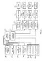
- FIG. 1is a functional block diagram of a fluid pumping system operable to embody an exemplary embodiment of the present invention.
- FIG. 2is a functional block diagram flow sensor and control circuit for the system appearing in FIG. 1 .
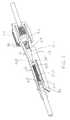
- FIG. 3is an isometric sectional view illustrating an exemplary flow sensor with integral resistor element.
- FIGS. 4A and 4Bare isometric views of an exemplary flow sensor with integral resistor showing the emitter and receiver.
- FIG. 4Cis a side view of the flow sensor embodiment appearing in FIGS. 4A and 4B .
- FIG. 5is a graph of pixel voltage output for photosensor array for determining flow sensor element location.
- FIG. 6is a graph of pixel voltage output for photosensor array with separate plots for flow sensor element location before and after a change in ball sensor element position.
- FIG. 7is a graph of pixel voltage differences for the plots appearing in FIG. 6 .
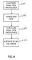
- FIG. 8is a flow diagram outlining an exemplary method for determining sensor element location in accordance with the present invention.
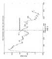
- FIG. 9is graph of flow sensor element position as a function of time during a period of an abrupt change in flow rate.
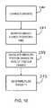
- FIG. 10is a flow diagram outlining an exemplary embodiment for sensing fluid viscosity in accordance with the present invention.
- FIG. 1depicts an exemplary flow control system 100 in accordance with an exemplary embodiment of the present invention.
- the systemincludes a pressure frame 10 that is of known total volume and contains within it an air bladder 20 and a flexible bag 30 that contains within it a liquid 40 to be delivered.
- the air bladder 20is connected to a charging tank 60 of known volume via a conduit or line 22 extending between an outlet of the tank 60 and an inlet of the bladder 20 .
- a pneumatic pump 50is pneumatically coupled to an inlet of the charging tank 60 via a line 52 .
- a bladder valve 24 in the line 22may be selectively opened and closed to selectively couple and decouple the outlet of the tank 60 with the inlet of the bladder 20 .
- the charging tankmay selectively be vented to atmosphere via a tank vent valve 62 .
- the air bladder 20may be vented to atmosphere via an optional bladder vent valve (not shown). Alternatively, the bladder 20 may be vented to atmosphere by opening the valves 24 and 62 .
- the tank 60is connected to a tank pressure sensor 66 and a tank temperature sensor 68 .
- the bladder 20is connected to a bladder pressure sensor 26 and a bladder temperature sensor 28 .
- the liquid 40is fluidically coupled to an output 70 via an inline flow sensor 80 , a fluid flow resistor 90 , and an output line 72 .
- the liquid 40may be, for example, a medication fluid, intravenous solution, blood product, or the like, to be infused and the output 70 may be, for example, a patient or subject in need thereof.
- the flow resistor 90is shown downstream of the in-line flow sensor 80 .
- the flow resistor 90may be positioned upstream of the flow sensor 80 .
- the flow resistor 90 and flow sensor 80may be separate or may be integrally formed.
- an embodiment of the fluid control system 100includes the pump 50 including a pump motor 51 , the bladder valve 24 including a bladder valve motor 25 , the tank vent valve 62 including a tank vent valve motor 63 , the flow sensor 80 including an optical sensor 824 and an optical emitter 822 , the flow resistor 90 including a flow resistor motor 91 , the tank pressure sensor 66 , tank temperature sensor 68 , bladder pressure sensor 26 , bladder temperature sensor 28 , a sensor processor 210 , a controller processor 212 , a pump motor controller 214 , a tank vent valve motor controller 216 , a bladder valve motor controller 218 and a flow resistor motor controller 220 .
- the sensor processor 210 , controller processor 212 , pump motor controller 214 , tank vent valve motor controller 216 , bladder valve motor controller 218 , and flow resistor motor controller 220may be implemented in a microprocessor, microcontroller, controller, embedded controller, or the like. Although the processors 210 and 212 and the controllers 214 - 220 are depicted in FIG. 2 as discrete modules or processors for conceptual simplicity and ease of exposition, it is to be appreciated that modules 210 - 214 can share common hardware. Well-known internal components for processing and control modules, such as power supplies, analog-to-digital converters, clock circuitry, etc., are not shown in FIG. 2 for simplicity and would be understood by persons skilled in the art.
- the controller processor 212controls the pump 50 via the pump motor controller 214 , the tank vent valve 62 via the tank vent valve controller 216 , the bladder valve 24 via the bladder valve controller 218 , and the flow resistor 90 via the flow resistor motor controller 220 .
- the controller processor 212may control one or more of the motors directly or via any other suitable known device.
- the controller 212may also control the application of power to the optical emitter 822 .
- the sensor processor 210receives a signal indicative of bladder temperature and pressure from the bladder temperature sensor 28 and bladder pressure sensor 26 , respectively.
- the sensor processor 210receives a signal indicative of tank temperature and pressure from the tank temperature sensor 68 and tank pressure sensor 66 , respectively.
- the sensor processor 210receives a signal from the optical sensor 824 indicative of the position of a flow sensor indicator element in the flow path as described below.
- FIG. 3shows an exemplary flow sensor 80 with integral flow resistor 90 .
- the flow resistor 90includes an inlet end 910 fluidly coupled to the fluid source 40 and an outlet 912 fluidly coupled to an inlet 810 of the flow sensor 80 .
- the flow sensor 80includes an outlet end 812 fluidly coupled to the output 50 such as the vasculature of a patient, e.g., via an IV catheter or cannula as generally known in the art.
- the inline sensor 80 and flow restrictor 90are depicted as an integral assembly in the embodiment of FIGS. 3 and 4 A- 4 C, it will be recognized that the flow resistor and the flow sensor units may be discrete assemblies fluidically coupled in serial fashion.
- the flow resistor 90includes a rotatable housing 914 , which may have a plurality of radially extending ribs or projections 916 forming a gear that may be selectively rotated by the motor 91 , which may be a stepper motor having an intermeshing member, or the like.
- the rotatable housing 914is coupled to an axially movable needle resistor 917 wherein rotating the housing 914 in one direction causes the needle resistor 917 to move in one axial direction and rotating the housing 914 in the opposite direction causes the needle resistor 917 to move in the opposite axial direction, for example, via helical threads formed on an interior surface of the rotatable housing member 914 .
- the needle resistoraxially moves between a first, closed position wherein the needle resistor engages a mating seat 918 and a fully open position.
- An annular gap 920 defined between the needle resistor 917 and the seat 918increases as the valve moves from the closed position to the fully open position, thereby providing a variable flow resistance, which varies as a function of the degree of rotation of the housing 914 .
- the flow sensor 80includes a housing portion 814 defining an axial channel or bore 816 receiving a ball member 818 .
- a spring member 820urges the ball member 818 in a direction opposite to the direction of flow.
- the spring member 820may be a coil spring (e.g., conical or cylindrical coil spring) or may be another resiliently compressible material such as a foam member, deflectable band or leaf spring, or the like.
- the spring 820bears against the ball 818 and applies a force to the ball in the direction opposite to the direction of fluid flow.
- An adjustment mechanismsuch as a threaded member engaging the fixed end of the spring 820 may be provided to axially advance or retract the fixed spring end to adjust the force preload of the spring 820 on the ball 818 .
- fluid flowwill exert a force on the sensor ball 818 against the urging of the spring 820 , which force increases as the flow rate increases.
- the ball 818thus moves until an equilibrium position is reached such that the force of the compression spring 820 on the ball 818 is balanced by the force of the fluid flow against the ball 818 .
- the optical emitter 822which may be, for example, an LED array, is provided on a first side of the housing 814 and the optical receiver 824 , which may be, a photosensitive array, charge-coupled device (CCD) array, photodiode array, complimentary metal oxide semiconductor (CMOS) digital detector array, or the like, is provided on a second side of the housing 814 opposite the first side.
- the optical emitter 822transmits light through the housing 814 and into the cavity 816 .
- the light incident upon the ball 818is transmitted through the ball 818 and opposite wall of the housing 814 to form a light intensity pattern on the optical sensor 824 .
- the ball 818may be a clear ball, e.g., formed of acrylic or other transparent polymeric material, which serves to dramatically reduce the optical path length of the fluid in the optical path between the emitter 822 and the sensor 824 in the vicinity of the ball 818 , thereby reducing the absorption of light by the fluid surrounding the ball in the flow passageway. Also, the use of a clear ball sensor element 818 allows the ball to function as a lens to transmit and focus the light.
- the optical transmitter 822may include one or more light source elements having a wavelength, for example, in the infrared (IR), visible, or ultraviolet (UV) region and the housing and ball member may be formed of a material that optically transmits light of the light source wavelength.
- the light source 822may be an array of light elements, such as LEDs, or laser, etc.
- the light sourcemay be segmented along the axis or may be a continuous, e.g., scanned or otherwise optically formed beam.
- the light sourcemay illuminate the detector array along its length simultaneously or by sequentially scanning along its length.
- the refractive effect of a transparent ball membermay have a focusing effect on the light passing therethrough that may be detected by the photosensor array.
- a nontransmissive ball 818may be employed and the ball position may be determined by detecting the position of a shadow cast by the ball on the photosensor array.
- the ball membermay have reflective surface and the optical sensor array may be positioned to detect light reflected from the surface of said ball.
- the output from the photosensitive arrayis a set of pixel voltage values which vary in accordance with the amount of light impinging on the each pixel of the photosensitive array.
- the pixel voltage valuesmay be sampled and digitized using an analog-to-digital converter and stored as digital data in an electronic storage medium as a numerical representation of the pixel output voltage levels, and thus, light intensity levels, along the detector array.
- the output of the optical sensor 824may be passed to the sensor processor 210 , which may include a position-detection module or circuitry wherein the axial position of the ball 818 within the channel 816 is determined.
- the axial position of the ball 816may in turn be used to determine a flow rate and/or calibrate or correlate ball positions with known flow rates calculated by other means such as plural volume measurements made using the method outlined in the aforementioned U.S. provisional application Ser. No. 60 and PCT Publication Nos. WO2007/098287, WO2007/098265, or WO2007/106232.
- FIG. 5there appears a graph of pixel voltage signal 230 of the photosensor array 824 as a function of pixel position.
- the pixel voltage measurementswere made using half-&-half as the fluid 40 and the flow sensor 80 was specifically detuned to represent a worst case scenario for the flow sensor and provide maximum challenge to the fluid control system.
- the graph of FIG. 5shows that the flow sensor signal is complex and difficult to analyze for the position 231 of the flow object, which is somewhat ambiguous.
- the ball 820was moved by the imposition of a modified flow rate and a subsequent measurement of the pixel voltage values of the photosensor array 824 was made (see signal 232 ).
- the new ball position 233based on the pixel voltage values, is likewise somewhat ambiguous.
- FIG. 7is a graph 234 of the pixel voltage differences between the first signal 230 and the second signal 232 .
- Subtracting the second signal from the first signalcancels or reduces common mode complexity and/or noise of the two signals and the first ball position 231 a and second ball position 233 a appear as clearly identifiable peaks, even though positions 231 and 233 based on the individual signals 230 and 232 , respectively, were ambiguous.
- the first signalcan be subtracted from the second signal, in which case the ball position can be similarly determined, but wherein the resultant function will be the negative function relative to the function 234 appearing in FIG. 7 , i.e., reflected about the x-axis.
- a method for detecting the flow sensor indicator elementis outlined in the flowchart of FIG. 8 .
- a first signal from the photodetector arrayis provided to the sensor processor 210 .
- the flow rateis changed.
- the flow ratemay be changed by introducing air into the charging tank 60 with the pump 50 to increase the pressure in the tank to a pressure greater than the pressure in the bladder 20 and opening the bladder valve 24 .
- the pressure increase in the bladder 20is preferably an abrupt pressure increase, e.g., to provide a step function change in fluid driving pressure, e.g., by popping or otherwise rapidly opening the valve 24 .
- the change in flow ratemay be a decrease in pressure.
- an optional bladder vent valve(not shown) may be provided for venting the bladder to reduce the pressure in the bladder 20 .
- a second signal from the photodetector arrayis provided to the sensor processor 210 representative of fluid flow rate at the new driving pressure.
- one the first and second signalsis subtracted from the other to provide clearly identifiable peaks representative of the ball axial position as described above.
- comparing ball position before and after an abrupt change in flow ratecan advantageously be used to provide a clear indication of sensor ball position.
- observation of ball position during the abrupt change in flow rateprovides the ability to measure viscosity of the fluid 40 .
- viscosity of the fluid 40can be determined by one or both of (1) the distance the ball moves in response to a change in flow rate (driving pressure); as well as (2) the rate at which the ball moves to the new position. The higher the viscosity, the further the ball moves in response to a change in flow rate. In addition, the higher the viscosity of the fluid, the longer it takes for the ball to assume its new equilibrium position in response to an abrupt change in flow rate.
- FIG. 9there appears a graph in which there is plotted a curve 260 representative of sensor ball position as a function of time during an abrupt increase in fluid driving pressure for a low viscosity fluid.
- the ballmoved from position 2 to position 11 , for a span of nine units of difference.
- the slope 262represents the speed at which the sensor ball moved from its initial position to its final position for the low viscosity fluid.
- a curve 264is representative of sensor ball position as a function of time for the same change in flow rate for a relatively high viscosity fluid.
- the ballmoved from position 0 to position 13, for a span of 13 units of difference with the high viscosity fluid.
- the slope 266represents the speed at which the sensor ball moved from its initial position to its final position for the high viscosity fluid.
- the slope 266 for the high viscosity fluidis lower than the slope 262 for the low viscosity fluid, and the distance moved for the higher viscosity was greater than the distance moved for the lower viscosity fluid, thus indicating that, for higher viscosities, the fluid will push the ball further, yet will do so at a lower speed taking significantly longer to reach its equilibrium position.
- the graphalso shows how the nominal starting positions 268 and 270 for the low and high viscosity fluids, respectively, for the same flow rates may vary due to the difference in viscosity.
- an abrupt change in flow rateis effected, e.g., by increasing the pressure in the tank 60 and popping the valve 24 to introduce a step change in fluid driving pressure.
- the axial position of the sensor ballis monitored as a function of time during the flow rate change until the ball assumes a new equilibrium position.
- the change in flow ratemay be effected by reducing the pressure in the bladder 20 , e.g., by reducing the pressure in the tank 60 and popping the valve 24 , or, by using an optional bladder vent valve (not shown).
- one or both of absolute position change and the rate of position change of the flow sensor elementis calculated, e.g., by comparing ball pixel position along the sensor array and/or by determining the average slope of position as a function of time for the period of time in which it took the ball to move from its initial equilibrium position at the initial flow rate to its new equilibrium at the new flow rate.
- the viscosity of the fluid being deliveredis determined from the change in ball position and/or rate of sensor element response, for example, by comparing calculated ball position change and/or rate thereof to prestored values for fluids of known viscosity, which may be stored in database, look up table, data file, etc.
- the type of fluid 40 to be infusedmay be input into the flow control system, e.g., by the operator using a user interface of the processor 210 and/or 212 .
- the type of fluid 40may be identified by reading a bar code (or other optically readable indicia) or radio frequency identification (RFID) tag on or in the fluid container, e.g., by a bar code (optical) scanner or RFID scanner.
- the viscosity as determined in step 292may then be checked to determine whether it is consistent with an expected fluid viscosity based on prestored viscosity characteristics associated with the fluid type input by the operator (e.g., stored in a database, lookup table, data file, memory, etc.).
- fluids or at least categories of fluidssuch as blood products (e.g., whole blood, platelets, plasma, immunoglobulins, packed red cells etc.), saline, dextrose, albumin, lactated ringers solution, amino acids, lipid emulsions, parenteral nutritional solutions, etc., will have different viscosity characteristics. If the viscosity determined at step 292 is different from the expected viscosity, the operator may be alerted to this potential error condition, thereby providing an additional safeguard.
- the observation of ball movement during an abrupt change fluid driving pressuremay also be used to detect other error conditions.
- the change in flow rate in response to a change in fluid driving pressureis indicative of the total systemic resistance. For example, if the ball position does not change after the fluid driving pressure is increased, the line may be occluded, and the operator may be alerted to this potential error condition.
- the pressure in the bladdermay be reduced to a lower level, e.g., using a bladder vent valve, if provided, or by reducing the pressure in the charging tank 60 (e.g., via tank vent valve 62 ) and opening the bladder valve 24 , e.g., to reduce the chance of an unwanted release bolus.
Landscapes
- Health & Medical Sciences (AREA)
- Fluid Mechanics (AREA)
- Physics & Mathematics (AREA)
- Heart & Thoracic Surgery (AREA)
- Vascular Medicine (AREA)
- Engineering & Computer Science (AREA)
- Anesthesiology (AREA)
- Biomedical Technology (AREA)
- General Physics & Mathematics (AREA)
- Hematology (AREA)
- Life Sciences & Earth Sciences (AREA)
- Animal Behavior & Ethology (AREA)
- General Health & Medical Sciences (AREA)
- Public Health (AREA)
- Veterinary Medicine (AREA)
- Infusion, Injection, And Reservoir Apparatuses (AREA)
Abstract
Description
Claims (18)
Priority Applications (3)
| Application Number | Priority Date | Filing Date | Title |
|---|---|---|---|
| US12/048,612US7847276B2 (en) | 2008-03-14 | 2008-03-14 | Impulse analysis for flow sensor-based fluid control system |
| US12/206,502US7895882B2 (en) | 2008-03-14 | 2008-09-08 | Density analysis for flow sensor-based fluid control system |
| US12/940,146US8067760B2 (en) | 2008-03-14 | 2010-11-05 | Impulse analysis for flow sensor-based fluid control system |
Applications Claiming Priority (1)
| Application Number | Priority Date | Filing Date | Title |
|---|---|---|---|
| US12/048,612US7847276B2 (en) | 2008-03-14 | 2008-03-14 | Impulse analysis for flow sensor-based fluid control system |
Related Child Applications (2)
| Application Number | Title | Priority Date | Filing Date |
|---|---|---|---|
| US12/206,502Continuation-In-PartUS7895882B2 (en) | 2008-03-14 | 2008-09-08 | Density analysis for flow sensor-based fluid control system |
| US12/940,146DivisionUS8067760B2 (en) | 2008-03-14 | 2010-11-05 | Impulse analysis for flow sensor-based fluid control system |
Publications (2)
| Publication Number | Publication Date |
|---|---|
| US20090234594A1 US20090234594A1 (en) | 2009-09-17 |
| US7847276B2true US7847276B2 (en) | 2010-12-07 |
Family
ID=41063963
Family Applications (2)
| Application Number | Title | Priority Date | Filing Date |
|---|---|---|---|
| US12/048,612Active2029-02-26US7847276B2 (en) | 2008-03-14 | 2008-03-14 | Impulse analysis for flow sensor-based fluid control system |
| US12/940,146ActiveUS8067760B2 (en) | 2008-03-14 | 2010-11-05 | Impulse analysis for flow sensor-based fluid control system |
Family Applications After (1)
| Application Number | Title | Priority Date | Filing Date |
|---|---|---|---|
| US12/940,146ActiveUS8067760B2 (en) | 2008-03-14 | 2010-11-05 | Impulse analysis for flow sensor-based fluid control system |
Country Status (1)
| Country | Link |
|---|---|
| US (2) | US7847276B2 (en) |
Cited By (24)
| Publication number | Priority date | Publication date | Assignee | Title |
|---|---|---|---|---|
| US20110168270A1 (en)* | 2008-12-18 | 2011-07-14 | Fluidnet Corporation | Extended range fluid flow resistor |
| US20130036824A1 (en)* | 2011-08-12 | 2013-02-14 | Fenwal, Inc. | Pressure sensor |
| US20140148757A1 (en)* | 2006-02-27 | 2014-05-29 | Jesse E. Ambrosina | Fluid control system and disposable assembly |
| US9339602B2 (en) | 2013-05-23 | 2016-05-17 | Turnpoint Medical Devices, Inc. | Pneumatically coupled direct drive fluid control system and process |
| US9995611B2 (en) | 2012-03-30 | 2018-06-12 | Icu Medical, Inc. | Air detection system and method for detecting air in a pump of an infusion system |
| US10022498B2 (en) | 2011-12-16 | 2018-07-17 | Icu Medical, Inc. | System for monitoring and delivering medication to a patient and method of using the same to minimize the risks associated with automated therapy |
| US10046112B2 (en) | 2013-05-24 | 2018-08-14 | Icu Medical, Inc. | Multi-sensor infusion system for detecting air or an occlusion in the infusion system |
| US10166328B2 (en) | 2013-05-29 | 2019-01-01 | Icu Medical, Inc. | Infusion system which utilizes one or more sensors and additional information to make an air determination regarding the infusion system |
| US10342917B2 (en) | 2014-02-28 | 2019-07-09 | Icu Medical, Inc. | Infusion system and method which utilizes dual wavelength optical air-in-line detection |
| US10430761B2 (en) | 2011-08-19 | 2019-10-01 | Icu Medical, Inc. | Systems and methods for a graphical interface including a graphical representation of medical data |
| US10463788B2 (en) | 2012-07-31 | 2019-11-05 | Icu Medical, Inc. | Patient care system for critical medications |
| US10596316B2 (en) | 2013-05-29 | 2020-03-24 | Icu Medical, Inc. | Infusion system and method of use which prevents over-saturation of an analog-to-digital converter |
| US10635784B2 (en) | 2007-12-18 | 2020-04-28 | Icu Medical, Inc. | User interface improvements for medical devices |
| US10656894B2 (en) | 2017-12-27 | 2020-05-19 | Icu Medical, Inc. | Synchronized display of screen content on networked devices |
| US10850024B2 (en) | 2015-03-02 | 2020-12-01 | Icu Medical, Inc. | Infusion system, device, and method having advanced infusion features |
| US11135360B1 (en) | 2020-12-07 | 2021-10-05 | Icu Medical, Inc. | Concurrent infusion with common line auto flush |
| US11246985B2 (en) | 2016-05-13 | 2022-02-15 | Icu Medical, Inc. | Infusion pump system and method with common line auto flush |
| US11278671B2 (en) | 2019-12-04 | 2022-03-22 | Icu Medical, Inc. | Infusion pump with safety sequence keypad |
| US11324888B2 (en) | 2016-06-10 | 2022-05-10 | Icu Medical, Inc. | Acoustic flow sensor for continuous medication flow measurements and feedback control of infusion |
| US11344673B2 (en) | 2014-05-29 | 2022-05-31 | Icu Medical, Inc. | Infusion system and pump with configurable closed loop delivery rate catch-up |
| US11344668B2 (en) | 2014-12-19 | 2022-05-31 | Icu Medical, Inc. | Infusion system with concurrent TPN/insulin infusion |
| US11883361B2 (en) | 2020-07-21 | 2024-01-30 | Icu Medical, Inc. | Fluid transfer devices and methods of use |
| US12350233B2 (en) | 2021-12-10 | 2025-07-08 | Icu Medical, Inc. | Medical fluid compounding systems with coordinated flow control |
| USD1091564S1 (en) | 2021-10-13 | 2025-09-02 | Icu Medical, Inc. | Display screen or portion thereof with graphical user interface for a medical device |
Families Citing this family (19)
| Publication number | Priority date | Publication date | Assignee | Title |
|---|---|---|---|---|
| EP2316505B1 (en) | 2006-03-14 | 2017-01-18 | University Of Southern California | Mems device for delivery of therapeutic agents |
| WO2009086112A2 (en) | 2007-12-20 | 2009-07-09 | University Of Southern California | Apparatus and methods for delivering therapeutic agents |
| US8986253B2 (en) | 2008-01-25 | 2015-03-24 | Tandem Diabetes Care, Inc. | Two chamber pumps and related methods |
| US8486278B2 (en) | 2008-05-08 | 2013-07-16 | Minipumps, Llc | Drug-delivery pumps and methods of manufacture |
| JP5719767B2 (en) | 2008-05-08 | 2015-05-20 | ミニパンプス, エルエルシー | Implantable pump and cannula therefor |
| US9849238B2 (en) | 2008-05-08 | 2017-12-26 | Minipumps, Llc | Drug-delivery pump with intelligent control |
| US8408421B2 (en) | 2008-09-16 | 2013-04-02 | Tandem Diabetes Care, Inc. | Flow regulating stopcocks and related methods |
| CA2737461A1 (en) | 2008-09-19 | 2010-03-25 | Tandem Diabetes Care, Inc. | Solute concentration measurement device and related methods |
| EP2724739B1 (en) | 2009-07-30 | 2015-07-01 | Tandem Diabetes Care, Inc. | Portable infusion pump system |
| KR101697388B1 (en) | 2009-08-18 | 2017-01-17 | 미니펌프스, 엘엘씨 | Electrolytic drug-delivery pump with adaptive control |
| CN103108665A (en)* | 2010-04-20 | 2013-05-15 | 迷你泵有限责任公司 | Electrolytically driven drug pump devices |
| US9180242B2 (en) | 2012-05-17 | 2015-11-10 | Tandem Diabetes Care, Inc. | Methods and devices for multiple fluid transfer |
| US9555186B2 (en) | 2012-06-05 | 2017-01-31 | Tandem Diabetes Care, Inc. | Infusion pump system with disposable cartridge having pressure venting and pressure feedback |
| US9173998B2 (en) | 2013-03-14 | 2015-11-03 | Tandem Diabetes Care, Inc. | System and method for detecting occlusions in an infusion pump |
| EP3068464B1 (en)* | 2013-11-15 | 2024-04-10 | Fresenius Kabi USA, LLC | Fluid control system and disposable assembly |
| US10935407B2 (en)* | 2017-07-25 | 2021-03-02 | Ecolab Usa Inc. | Fluid flow meter with viscosity correction |
| CN111469337A (en)* | 2020-04-21 | 2020-07-31 | 金晓 | Injection molding device with adjustable injection molding pressure based on light sensation control |
| EP4573353A1 (en)* | 2022-08-15 | 2025-06-25 | Preddio Technologies Inc. | Optical sensor |
| WO2025117543A1 (en)* | 2023-11-28 | 2025-06-05 | Flextronics Ap, Llc | Fluidic analysis and control through image processing |
Citations (26)
| Publication number | Priority date | Publication date | Assignee | Title |
|---|---|---|---|---|
| US4090514A (en) | 1976-10-22 | 1978-05-23 | Howard Helmut Hinck | Pressure infusion device |
| US4191184A (en) | 1977-01-06 | 1980-03-04 | Carlisle Jeffrey A | Intravenous infusion regulation system with reciprocal metering means |
| US4470758A (en) | 1981-11-12 | 1984-09-11 | Oximetrix, Inc. | Intravenous fluid pump monitor |
| US4539005A (en) | 1983-10-24 | 1985-09-03 | Greenblatt Gordon M | Blood infusion apparatus and method |
| US4561298A (en) | 1983-06-30 | 1985-12-31 | Pond John B | Volume measurement system |
| US4976162A (en) | 1987-09-03 | 1990-12-11 | Kamen Dean L | Enhanced pressure measurement flow control system |
| US5207645A (en) | 1991-06-25 | 1993-05-04 | Medication Delivery Devices | Infusion pump, treatment fluid bag therefor, and method for the use thereof |
| US5348539A (en) | 1993-06-29 | 1994-09-20 | Glenn Herskowitz | Infusion pump for use with prepackaged IV bags |
| US5464391A (en) | 1994-03-03 | 1995-11-07 | Northgate Technologies Inc. | Irrigation system for a surgical site |
| US5533381A (en) | 1994-06-10 | 1996-07-09 | Seale; Joseph B. | Conversion of liquid volume, density, and viscosity to frequency signals |
| US5554123A (en) | 1994-10-31 | 1996-09-10 | Glenn Herskowitz | Portable infusion pump |
| US5597042A (en) | 1995-02-09 | 1997-01-28 | Baker Hughes Incorporated | Method for controlling production wells having permanent downhole formation evaluation sensors |
| US5624409A (en) | 1994-06-10 | 1997-04-29 | Fluidsense Corporation | Variable-pulse dynamic fluid flow controller |
| USRE35501E (en) | 1991-06-25 | 1997-05-06 | Medication Delivery Devices | Infusion pump, treatment fluid bag therefor, and method for the use thereof |
| US5769608A (en) | 1994-06-10 | 1998-06-23 | P.D. Coop, Inc. | Resonant system to pump liquids, measure volume, and detect bubbles |
| US5788674A (en) | 1996-03-05 | 1998-08-04 | Medication Delivery Devices, Inc. | Apparatus and method for limiting free-flow in an infusion system |
| US6275284B1 (en) | 1998-04-23 | 2001-08-14 | Nova Gas Transmission Ltd. | Pipeline optical flow meter |
| US6398760B1 (en) | 1999-10-01 | 2002-06-04 | Baxter International, Inc. | Volumetric infusion pump with servo valve control |
| US6461323B2 (en) | 2000-05-03 | 2002-10-08 | Reginald H. Fowler | Surgical system pump with flow sensor and method therefor |
| US6642999B2 (en) | 2000-04-13 | 2003-11-04 | Robert Bosch Gmbh | Method and device for analyzing flows |
| US6641562B1 (en) | 2000-05-10 | 2003-11-04 | Hps Medical, Inc. | Apparatus and method of intravenous fluid infusion |
| US6685668B1 (en) | 2000-07-31 | 2004-02-03 | Abbott Laboratories | Closed-loop IV fluid flow control |
| US20050235733A1 (en) | 1999-12-17 | 2005-10-27 | Holst Peter A | Method for compensating for pressure differences across valves in cassette type IV pump |
| WO2007098287A2 (en) | 2006-02-27 | 2007-08-30 | Fluidnet Corporation | Flow control system and method with variable pressure and variable resistance |
| WO2007106232A2 (en) | 2006-02-27 | 2007-09-20 | Fluidnet Corporation | Volume measurement using gas laws |
| US7503903B2 (en) | 2004-02-20 | 2009-03-17 | Fluidnet Corporation | Automated fluid flow control system |
Family Cites Families (2)
| Publication number | Priority date | Publication date | Assignee | Title |
|---|---|---|---|---|
| KR20100074249A (en)* | 2007-10-04 | 2010-07-01 | 백스터 인터내셔널 인코포레이티드 | Apparatus for a fluid delivery system with controlled fluid flow rate |
| US7895882B2 (en) | 2008-03-14 | 2011-03-01 | Fluidnet Corporation | Density analysis for flow sensor-based fluid control system |
- 2008
- 2008-03-14USUS12/048,612patent/US7847276B2/enactiveActive
- 2010
- 2010-11-05USUS12/940,146patent/US8067760B2/enactiveActive
Patent Citations (33)
| Publication number | Priority date | Publication date | Assignee | Title |
|---|---|---|---|---|
| US4090514A (en) | 1976-10-22 | 1978-05-23 | Howard Helmut Hinck | Pressure infusion device |
| US4191184A (en) | 1977-01-06 | 1980-03-04 | Carlisle Jeffrey A | Intravenous infusion regulation system with reciprocal metering means |
| US4470758A (en) | 1981-11-12 | 1984-09-11 | Oximetrix, Inc. | Intravenous fluid pump monitor |
| US4561298A (en) | 1983-06-30 | 1985-12-31 | Pond John B | Volume measurement system |
| US4539005A (en) | 1983-10-24 | 1985-09-03 | Greenblatt Gordon M | Blood infusion apparatus and method |
| US4976162A (en) | 1987-09-03 | 1990-12-11 | Kamen Dean L | Enhanced pressure measurement flow control system |
| US5584811A (en) | 1991-06-25 | 1996-12-17 | Medication Delivery Devices, Inc. | Infusion pump, treatment fluid bag therefor, and method for the use thereof |
| US5207645A (en) | 1991-06-25 | 1993-05-04 | Medication Delivery Devices | Infusion pump, treatment fluid bag therefor, and method for the use thereof |
| US5308335A (en) | 1991-06-25 | 1994-05-03 | Medication Delivery Devices | Infusion pump, treatment fluid bag therefor, and method for the use thereof |
| US5433704A (en) | 1991-06-25 | 1995-07-18 | Medication Delivery Devices | Infusion pump, treatment fluid bag therefor, and method for the use thereof |
| US5743878A (en) | 1991-06-25 | 1998-04-28 | Medication Delivery Devices, Inc. | Infusion pump, treatment fluid bag therefor, and method for the use thereof |
| USRE35501E (en) | 1991-06-25 | 1997-05-06 | Medication Delivery Devices | Infusion pump, treatment fluid bag therefor, and method for the use thereof |
| US5348539A (en) | 1993-06-29 | 1994-09-20 | Glenn Herskowitz | Infusion pump for use with prepackaged IV bags |
| US5464391A (en) | 1994-03-03 | 1995-11-07 | Northgate Technologies Inc. | Irrigation system for a surgical site |
| US5624409A (en) | 1994-06-10 | 1997-04-29 | Fluidsense Corporation | Variable-pulse dynamic fluid flow controller |
| US5533381A (en) | 1994-06-10 | 1996-07-09 | Seale; Joseph B. | Conversion of liquid volume, density, and viscosity to frequency signals |
| US5769608A (en) | 1994-06-10 | 1998-06-23 | P.D. Coop, Inc. | Resonant system to pump liquids, measure volume, and detect bubbles |
| US5554123A (en) | 1994-10-31 | 1996-09-10 | Glenn Herskowitz | Portable infusion pump |
| US5597042A (en) | 1995-02-09 | 1997-01-28 | Baker Hughes Incorporated | Method for controlling production wells having permanent downhole formation evaluation sensors |
| US5788674A (en) | 1996-03-05 | 1998-08-04 | Medication Delivery Devices, Inc. | Apparatus and method for limiting free-flow in an infusion system |
| US6275284B1 (en) | 1998-04-23 | 2001-08-14 | Nova Gas Transmission Ltd. | Pipeline optical flow meter |
| US6398760B1 (en) | 1999-10-01 | 2002-06-04 | Baxter International, Inc. | Volumetric infusion pump with servo valve control |
| US20050235733A1 (en) | 1999-12-17 | 2005-10-27 | Holst Peter A | Method for compensating for pressure differences across valves in cassette type IV pump |
| US6642999B2 (en) | 2000-04-13 | 2003-11-04 | Robert Bosch Gmbh | Method and device for analyzing flows |
| US6461323B2 (en) | 2000-05-03 | 2002-10-08 | Reginald H. Fowler | Surgical system pump with flow sensor and method therefor |
| US6641562B1 (en) | 2000-05-10 | 2003-11-04 | Hps Medical, Inc. | Apparatus and method of intravenous fluid infusion |
| US6685668B1 (en) | 2000-07-31 | 2004-02-03 | Abbott Laboratories | Closed-loop IV fluid flow control |
| US6981960B2 (en) | 2000-07-31 | 2006-01-03 | Hospira, Inc. | Closed-loop IV fluid flow control |
| US7503903B2 (en) | 2004-02-20 | 2009-03-17 | Fluidnet Corporation | Automated fluid flow control system |
| WO2007098287A2 (en) | 2006-02-27 | 2007-08-30 | Fluidnet Corporation | Flow control system and method with variable pressure and variable resistance |
| WO2007098265A2 (en) | 2006-02-27 | 2007-08-30 | Fluidnet Corporation | Flow sensor calibrated by volume changes |
| WO2007106232A2 (en) | 2006-02-27 | 2007-09-20 | Fluidnet Corporation | Volume measurement using gas laws |
| US20100063765A1 (en)* | 2006-02-27 | 2010-03-11 | Fluidnet Corporation | Flow Sensor Calibrated by Volume Changes |
Non-Patent Citations (3)
| Title |
|---|
| International Search Report and Written Opinion of the International Searching Authority dated Apr. 1, 2008, received in PCT/US2007/04945. |
| International Search Report and Written Opinion of the International Searching Authority dated Dec. 4, 2007, received in PCT/US2007/05095. |
| International Search Report and Written Opinion of the International Searching Authority dated Sep. 11, 2008, received in PCT/US2007/02039. |
Cited By (52)
| Publication number | Priority date | Publication date | Assignee | Title |
|---|---|---|---|---|
| US20140148757A1 (en)* | 2006-02-27 | 2014-05-29 | Jesse E. Ambrosina | Fluid control system and disposable assembly |
| US10010686B2 (en)* | 2006-02-27 | 2018-07-03 | Ivenix, Inc. | Fluid control system and disposable assembly |
| US10635784B2 (en) | 2007-12-18 | 2020-04-28 | Icu Medical, Inc. | User interface improvements for medical devices |
| US20110168270A1 (en)* | 2008-12-18 | 2011-07-14 | Fluidnet Corporation | Extended range fluid flow resistor |
| US20130036824A1 (en)* | 2011-08-12 | 2013-02-14 | Fenwal, Inc. | Pressure sensor |
| US9074951B2 (en)* | 2011-08-12 | 2015-07-07 | Fenwal, Inc. | Blood processing system |
| US11972395B2 (en) | 2011-08-19 | 2024-04-30 | Icu Medical, Inc. | Systems and methods for a graphical interface including a graphical representation of medical data |
| US11599854B2 (en) | 2011-08-19 | 2023-03-07 | Icu Medical, Inc. | Systems and methods for a graphical interface including a graphical representation of medical data |
| US11004035B2 (en) | 2011-08-19 | 2021-05-11 | Icu Medical, Inc. | Systems and methods for a graphical interface including a graphical representation of medical data |
| US12346879B2 (en) | 2011-08-19 | 2025-07-01 | Icu Medical, Inc. | Systems and methods for a graphical interface including a graphical representation of medical data |
| US10430761B2 (en) | 2011-08-19 | 2019-10-01 | Icu Medical, Inc. | Systems and methods for a graphical interface including a graphical representation of medical data |
| US11376361B2 (en) | 2011-12-16 | 2022-07-05 | Icu Medical, Inc. | System for monitoring and delivering medication to a patient and method of using the same to minimize the risks associated with automated therapy |
| US10022498B2 (en) | 2011-12-16 | 2018-07-17 | Icu Medical, Inc. | System for monitoring and delivering medication to a patient and method of using the same to minimize the risks associated with automated therapy |
| US11933650B2 (en) | 2012-03-30 | 2024-03-19 | Icu Medical, Inc. | Air detection system and method for detecting air in a pump of an infusion system |
| US10578474B2 (en) | 2012-03-30 | 2020-03-03 | Icu Medical, Inc. | Air detection system and method for detecting air in a pump of an infusion system |
| US9995611B2 (en) | 2012-03-30 | 2018-06-12 | Icu Medical, Inc. | Air detection system and method for detecting air in a pump of an infusion system |
| US12280239B2 (en) | 2012-07-31 | 2025-04-22 | Icu Medical, Inc. | Patient care system for critical medications |
| US10463788B2 (en) | 2012-07-31 | 2019-11-05 | Icu Medical, Inc. | Patient care system for critical medications |
| US11623042B2 (en) | 2012-07-31 | 2023-04-11 | Icu Medical, Inc. | Patient care system for critical medications |
| US10350352B2 (en) | 2013-05-23 | 2019-07-16 | Turnpoint Medical Devices, Inc. | Pneumatically coupled fluid control system and process with air detection and elimination |
| US10342920B2 (en) | 2013-05-23 | 2019-07-09 | Turnpoint Medical Devices, Inc. | Pneumatically coupled direct drive fluid control system and process |
| US9339602B2 (en) | 2013-05-23 | 2016-05-17 | Turnpoint Medical Devices, Inc. | Pneumatically coupled direct drive fluid control system and process |
| US10874793B2 (en) | 2013-05-24 | 2020-12-29 | Icu Medical, Inc. | Multi-sensor infusion system for detecting air or an occlusion in the infusion system |
| US12048831B2 (en) | 2013-05-24 | 2024-07-30 | Icu Medical, Inc. | Multi-sensor infusion system for detecting air or an occlusion in the infusion system |
| US10046112B2 (en) | 2013-05-24 | 2018-08-14 | Icu Medical, Inc. | Multi-sensor infusion system for detecting air or an occlusion in the infusion system |
| US12059551B2 (en) | 2013-05-29 | 2024-08-13 | Icu Medical, Inc. | Infusion system and method of use which prevents over-saturation of an analog-to-digital converter |
| US10166328B2 (en) | 2013-05-29 | 2019-01-01 | Icu Medical, Inc. | Infusion system which utilizes one or more sensors and additional information to make an air determination regarding the infusion system |
| US11433177B2 (en) | 2013-05-29 | 2022-09-06 | Icu Medical, Inc. | Infusion system which utilizes one or more sensors and additional information to make an air determination regarding the infusion system |
| US11596737B2 (en) | 2013-05-29 | 2023-03-07 | Icu Medical, Inc. | Infusion system and method of use which prevents over-saturation of an analog-to-digital converter |
| US10596316B2 (en) | 2013-05-29 | 2020-03-24 | Icu Medical, Inc. | Infusion system and method of use which prevents over-saturation of an analog-to-digital converter |
| US12083310B2 (en) | 2014-02-28 | 2024-09-10 | Icu Medical, Inc. | Infusion system and method which utilizes dual wavelength optical air-in-line detection |
| US10342917B2 (en) | 2014-02-28 | 2019-07-09 | Icu Medical, Inc. | Infusion system and method which utilizes dual wavelength optical air-in-line detection |
| US11344673B2 (en) | 2014-05-29 | 2022-05-31 | Icu Medical, Inc. | Infusion system and pump with configurable closed loop delivery rate catch-up |
| US11344668B2 (en) | 2014-12-19 | 2022-05-31 | Icu Medical, Inc. | Infusion system with concurrent TPN/insulin infusion |
| US12115337B2 (en) | 2015-03-02 | 2024-10-15 | Icu Medical, Inc. | Infusion system, device, and method having advanced infusion features |
| US10850024B2 (en) | 2015-03-02 | 2020-12-01 | Icu Medical, Inc. | Infusion system, device, and method having advanced infusion features |
| US12201811B2 (en) | 2016-05-13 | 2025-01-21 | Icu Medical, Inc. | Infusion pump system and method with common line auto flush |
| US11246985B2 (en) | 2016-05-13 | 2022-02-15 | Icu Medical, Inc. | Infusion pump system and method with common line auto flush |
| US12076531B2 (en) | 2016-06-10 | 2024-09-03 | Icu Medical, Inc. | Acoustic flow sensor for continuous medication flow measurements and feedback control of infusion |
| US11324888B2 (en) | 2016-06-10 | 2022-05-10 | Icu Medical, Inc. | Acoustic flow sensor for continuous medication flow measurements and feedback control of infusion |
| US10656894B2 (en) | 2017-12-27 | 2020-05-19 | Icu Medical, Inc. | Synchronized display of screen content on networked devices |
| US11029911B2 (en) | 2017-12-27 | 2021-06-08 | Icu Medical, Inc. | Synchronized display of screen content on networked devices |
| US11868161B2 (en) | 2017-12-27 | 2024-01-09 | Icu Medical, Inc. | Synchronized display of screen content on networked devices |
| US12333201B2 (en) | 2017-12-27 | 2025-06-17 | Icu Medical, Inc. | Synchronized display of screen content on networked devices |
| US12268843B2 (en) | 2019-12-04 | 2025-04-08 | Icu Medical, Inc. | Infusion pump with safety sequence keypad |
| US11278671B2 (en) | 2019-12-04 | 2022-03-22 | Icu Medical, Inc. | Infusion pump with safety sequence keypad |
| US11883361B2 (en) | 2020-07-21 | 2024-01-30 | Icu Medical, Inc. | Fluid transfer devices and methods of use |
| US12310921B2 (en) | 2020-07-21 | 2025-05-27 | Icu Medical, Inc. | Fluid transfer devices and methods of use |
| US11135360B1 (en) | 2020-12-07 | 2021-10-05 | Icu Medical, Inc. | Concurrent infusion with common line auto flush |
| US12390586B2 (en) | 2020-12-07 | 2025-08-19 | Icu Medical, Inc. | Concurrent infusion with common line auto flush |
| USD1091564S1 (en) | 2021-10-13 | 2025-09-02 | Icu Medical, Inc. | Display screen or portion thereof with graphical user interface for a medical device |
| US12350233B2 (en) | 2021-12-10 | 2025-07-08 | Icu Medical, Inc. | Medical fluid compounding systems with coordinated flow control |
Also Published As
| Publication number | Publication date |
|---|---|
| US20110046900A1 (en) | 2011-02-24 |
| US20090234594A1 (en) | 2009-09-17 |
| US8067760B2 (en) | 2011-11-29 |
Similar Documents
| Publication | Publication Date | Title |
|---|---|---|
| US7847276B2 (en) | Impulse analysis for flow sensor-based fluid control system | |
| US7895882B2 (en) | Density analysis for flow sensor-based fluid control system | |
| US7654982B2 (en) | Flow control system and method with variable pressure and variable resistance | |
| WO2007098287A2 (en) | Flow control system and method with variable pressure and variable resistance | |
| US11819662B2 (en) | MEMS fluid pump with integrated pressure sensor for dysfunction detection | |
| EP0319275B1 (en) | Patient-side occlusion detection system for a medication infusion system | |
| AU737494B2 (en) | Infusion device with disposable elements | |
| JP6306648B2 (en) | System apparatus for injecting fluid | |
| US4950235A (en) | Container-side occlusion detection system for a medication infusion system | |
| US7232430B2 (en) | Air-in-line and pressure detection | |
| MXPA02006732A (en) | Occlusion detection method and system for ambulatory drug infusion pump. | |
| WO2012126744A1 (en) | Infusion system and method of integrity testing and leak detection | |
| US20240133911A1 (en) | Air detection and measurement system for fluid injector | |
| US20200338263A1 (en) | Automated Medical Infusion Device and Method with Improved Accuracy and Safety Characteristics and MRI-Safe Capability | |
| JP6081962B2 (en) | Medical pump device | |
| JP2017064525A (en) | Medical pumping device | |
| US12253398B2 (en) | Flow sensor system and method for using same |
Legal Events
| Date | Code | Title | Description |
|---|---|---|---|
| AS | Assignment | Owner name:FLUIDNET CORPORATION, NEW HAMPSHIRE Free format text:ASSIGNMENT OF ASSIGNORS INTEREST;ASSIGNORS:CARLISLE, JEFFREY A.;KRAMER, CHARLES E.;KIRKMAN, JOHN M., JR.;AND OTHERS;REEL/FRAME:020656/0939;SIGNING DATES FROM 20080229 TO 20080311 Owner name:FLUIDNET CORPORATION, NEW HAMPSHIRE Free format text:ASSIGNMENT OF ASSIGNORS INTEREST;ASSIGNORS:CARLISLE, JEFFREY A.;KRAMER, CHARLES E.;KIRKMAN, JOHN M., JR.;AND OTHERS;SIGNING DATES FROM 20080229 TO 20080311;REEL/FRAME:020656/0939 | |
| STCF | Information on status: patent grant | Free format text:PATENTED CASE | |
| FPAY | Fee payment | Year of fee payment:4 | |
| AS | Assignment | Owner name:IVENIX, INC., MASSACHUSETTS Free format text:CHANGE OF NAME;ASSIGNOR:FLUIDNET CORPORATION;REEL/FRAME:033260/0800 Effective date:20140327 | |
| MAFP | Maintenance fee payment | Free format text:PAYMENT OF MAINTENANCE FEE, 8TH YR, SMALL ENTITY (ORIGINAL EVENT CODE: M2552) Year of fee payment:8 | |
| AS | Assignment | Owner name:IVENIX, INC., MASSACHUSETTS Free format text:CHANGE OF ADDRESS;ASSIGNOR:IVENIX, INC.;REEL/FRAME:050600/0256 Effective date:20191002 | |
| AS | Assignment | Owner name:SILICON VALLEY BANK, AS ADMINISTRATIVE AND COLLATERAL AGENT, CALIFORNIA Free format text:SECURITY INTEREST;ASSIGNOR:IVENIX, INC.;REEL/FRAME:056342/0346 Effective date:20210525 | |
| MAFP | Maintenance fee payment | Free format text:PAYMENT OF MAINTENANCE FEE, 12TH YEAR, LARGE ENTITY (ORIGINAL EVENT CODE: M1553); ENTITY STATUS OF PATENT OWNER: LARGE ENTITY Year of fee payment:12 | |
| AS | Assignment | Owner name:IVENIX, INC., MASSACHUSETTS Free format text:RELEASE OF SECURITY INTEREST IN INTELLECTUAL PROPERTY;ASSIGNOR:SILICON VALLEY BANK;REEL/FRAME:059848/0090 Effective date:20220503 | |
| AS | Assignment | Owner name:FRESENIUS KABI USA, LLC, ILLINOIS Free format text:MERGER;ASSIGNOR:IVENIX, INC.;REEL/FRAME:059844/0266 Effective date:20220503 | |
| FEPP | Fee payment procedure | Free format text:ENTITY STATUS SET TO UNDISCOUNTED (ORIGINAL EVENT CODE: BIG.); ENTITY STATUS OF PATENT OWNER: LARGE ENTITY |