US7846167B2 - Driver assembly and fastener apparatus - Google Patents
Driver assembly and fastener apparatusDownload PDFInfo
- Publication number
- US7846167B2 US7846167B2US11/593,447US59344706AUS7846167B2US 7846167 B2US7846167 B2US 7846167B2US 59344706 AUS59344706 AUS 59344706AUS 7846167 B2US7846167 B2US 7846167B2
- Authority
- US
- United States
- Prior art keywords
- fastener
- shaft
- driver
- generally
- head
- Prior art date
- Legal status (The legal status is an assumption and is not a legal conclusion. Google has not performed a legal analysis and makes no representation as to the accuracy of the status listed.)
- Expired - Fee Related, expires
Links
Images


Classifications
- A—HUMAN NECESSITIES
- A61—MEDICAL OR VETERINARY SCIENCE; HYGIENE
- A61B—DIAGNOSIS; SURGERY; IDENTIFICATION
- A61B17/00—Surgical instruments, devices or methods
- A61B17/56—Surgical instruments or methods for treatment of bones or joints; Devices specially adapted therefor
- A61B17/58—Surgical instruments or methods for treatment of bones or joints; Devices specially adapted therefor for osteosynthesis, e.g. bone plates, screws or setting implements
- A61B17/68—Internal fixation devices, including fasteners and spinal fixators, even if a part thereof projects from the skin
- A61B17/84—Fasteners therefor or fasteners being internal fixation devices
- A61B17/86—Pins or screws or threaded wires; nuts therefor
- A61B17/8605—Heads, i.e. proximal ends projecting from bone
- A61B17/861—Heads, i.e. proximal ends projecting from bone specially shaped for gripping driver
- A61B17/862—Heads, i.e. proximal ends projecting from bone specially shaped for gripping driver at the periphery of the screw head
- A—HUMAN NECESSITIES
- A61—MEDICAL OR VETERINARY SCIENCE; HYGIENE
- A61B—DIAGNOSIS; SURGERY; IDENTIFICATION
- A61B17/00—Surgical instruments, devices or methods
- A61B17/56—Surgical instruments or methods for treatment of bones or joints; Devices specially adapted therefor
- A61B17/58—Surgical instruments or methods for treatment of bones or joints; Devices specially adapted therefor for osteosynthesis, e.g. bone plates, screws or setting implements
- A61B17/88—Osteosynthesis instruments; Methods or means for implanting or extracting internal or external fixation devices
- A61B17/8863—Apparatus for shaping or cutting osteosynthesis equipment by medical personnel
- A—HUMAN NECESSITIES
- A61—MEDICAL OR VETERINARY SCIENCE; HYGIENE
- A61B—DIAGNOSIS; SURGERY; IDENTIFICATION
- A61B17/00—Surgical instruments, devices or methods
- A61B17/56—Surgical instruments or methods for treatment of bones or joints; Devices specially adapted therefor
- A61B17/58—Surgical instruments or methods for treatment of bones or joints; Devices specially adapted therefor for osteosynthesis, e.g. bone plates, screws or setting implements
- A61B17/88—Osteosynthesis instruments; Methods or means for implanting or extracting internal or external fixation devices
- A61B17/8875—Screwdrivers, spanners or wrenches
- A61B17/8877—Screwdrivers, spanners or wrenches characterised by the cross-section of the driver bit
- A61B17/8883—Screwdrivers, spanners or wrenches characterised by the cross-section of the driver bit the driver bit acting on the periphery of the screw head
- A—HUMAN NECESSITIES
- A61—MEDICAL OR VETERINARY SCIENCE; HYGIENE
- A61B—DIAGNOSIS; SURGERY; IDENTIFICATION
- A61B17/00—Surgical instruments, devices or methods
- A61B17/56—Surgical instruments or methods for treatment of bones or joints; Devices specially adapted therefor
- A61B17/58—Surgical instruments or methods for treatment of bones or joints; Devices specially adapted therefor for osteosynthesis, e.g. bone plates, screws or setting implements
- A61B17/88—Osteosynthesis instruments; Methods or means for implanting or extracting internal or external fixation devices
- A61B17/8875—Screwdrivers, spanners or wrenches
- A61B17/8886—Screwdrivers, spanners or wrenches holding the screw head
- A61B17/8888—Screwdrivers, spanners or wrenches holding the screw head at its central region
- A—HUMAN NECESSITIES
- A61—MEDICAL OR VETERINARY SCIENCE; HYGIENE
- A61B—DIAGNOSIS; SURGERY; IDENTIFICATION
- A61B17/00—Surgical instruments, devices or methods
- A61B2017/0046—Surgical instruments, devices or methods with a releasable handle; with handle and operating part separable
- A—HUMAN NECESSITIES
- A61—MEDICAL OR VETERINARY SCIENCE; HYGIENE
- A61B—DIAGNOSIS; SURGERY; IDENTIFICATION
- A61B90/00—Instruments, implements or accessories specially adapted for surgery or diagnosis and not covered by any of the groups A61B1/00 - A61B50/00, e.g. for luxation treatment or for protecting wound edges
- A61B90/03—Automatic limiting or abutting means, e.g. for safety
- A61B2090/037—Automatic limiting or abutting means, e.g. for safety with a frangible part, e.g. by reduced diameter
Definitions
- the present teachingsrelate to a driver assembly, and more specifically to a medical driver assembly.
- Medical driverstypically have unique driving arrangements for different fastener sizes. Many drivers and fasteners are also difficult to manufacture due to tight tolerances required for interference-fit engagements. Current fasteners may also be difficult to track once coupled to a structure.
- a driver assemblymay include a fastener and a driver.
- the fastenermay have a head with upper and lower surfaces.
- An engagement portionmay be located in the upper surface proximate a perimeter portion thereof.
- a shankmay extend from the lower surface of the head and a breakaway portion may extend from the upper surface of the head.
- the drivermay include a shaft having a body with a first end having a fastener-engaging portion.
- the fastener-engaging portionmay have an outer driving geometry engaged with the engagement portion of the fastener when in an engaged position.
- the first endmay further include an opening therein. The opening may receive at least a portion of the breakaway portion when in the engaged position.
- FIG. 1is a perspective view of a first driver assembly
- FIG. 2is an exploded view of the driver assembly of FIG. 1 ;
- FIG. 3is a fragmentary sectional view of the driver assembly shown in FIG. 1 ;
- FIG. 4is a perspective view of the fastener shown in FIG. 1 ;
- FIG. 5is a perspective view of an additional fastener
- FIG. 6is a perspective view of an additional fastener
- FIG. 7is a perspective view of an additional fastener
- FIG. 8is a perspective view of an additional fastener
- FIG. 9is a perspective view of an additional fastener
- FIG. 10is a section view of the fastener shown in FIG. 9 ;
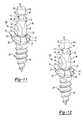
- FIG. 11is a perspective view of an additional fastener
- FIG. 12is a perspective view of an additional fastener
- FIG. 13is a perspective exploded view of an additional fastener
- FIG. 14is a perspective exploded view of an additional fastener
- FIG. 15is a perspective exploded view of an additional fastener
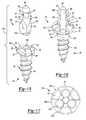
- FIG. 16is a perspective view of an additional fastener
- FIG. 17is a top plan view of a head portion of an additional fastener
- FIG. 18is a perspective view of an additional fastener
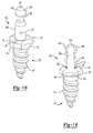
- FIG. 19is a perspective view of an additional fastener
- FIG. 20is a perspective view of an additional fastener
- FIG. 21is a perspective view of an additional fastener
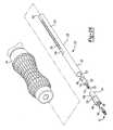
- FIG. 22is a fragmentary perspective view of an additional shaft for a driver
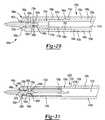
- FIG. 23is a sectional view of the driver handle shown in FIG. 1 ;
- FIG. 24is a perspective view of a power driver
- FIG. 25is a perspective view of an additional driver assembly
- FIG. 26is an exploded view of the driver assembly of FIG. 25 ;
- FIG. 27is a fragmentary sectional view of the driver assembly shown in FIG. 25 ;
- FIG. 28is an exploded view of an additional driver assembly
- FIG. 29is a fragmentary sectional view of the driver assembly shown in FIG. 28 ;
- FIG. 30is an exploded view of an additional driver assembly
- FIG. 31is a fragmentary sectional view of the driver assembly shown in FIG. 30 ;
- FIG. 32is an exploded view of an additional driver assembly
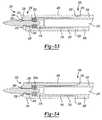
- FIG. 33is a fragmentary sectional view of the driver assembly shown in FIG. 32 ;
- FIG. 34is a fragmentary sectional view of the driver assembly shown in FIG. 32 with an alternate retaining member;
- FIG. 35is an exploded perspective view of an additional driver assembly
- FIG. 36is a fragmentary section view of the driver assembly of FIG. 35 ;
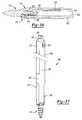
- FIG. 37is a fragmentary perspective view of the driver assembly of FIG. 35 ;
- FIG. 38is a fragmentary section view of an additional driver assembly
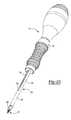
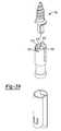
- FIG. 39is a fragmentary exploded perspective view of an additional driver assembly.
- FIG. 40is a fragmentary section view of the driver assembly of FIG. 39 .
- FIGS. 1-3generally show a driver assembly 10 , which may include a fastener 12 and a driver 14 .
- a variety of fastenersare shown in FIGS. 4-21 . Numerous features may be common between the fasteners shown in FIGS. 4-21 . Therefore, it is understood that the description of fastener 12 shown in FIG. 4 applies equally to FIGS. 5-21 where common reference numerals are used.
- fastener 12may include a head 16 , a post 18 and a shank 20 .
- the head 16may include an upper surface 22 , a lower surface 24 and a perimeter portion 26 disposed between the upper and lower surfaces 22 , 24 .
- Perimeter portion 26may be generally circular (as seen in FIGS. 4-16 and 18 - 21 ) or, as seen in FIG. 17 , perimeter portion 26 m may include alignment features such as flats 27 for aligning fastener 12 m within a cartridge (not shown).
- the upper surface 22may include a driving geometry 28 near the perimeter portion 26 .
- the driving geometry 28may be in the form of arcuate recesses 30 . While three (3) arcuate recesses 30 are shown in FIG.
- a fastener 12 omay include two recesses 30 o .
- Recesses 30do not need to be arcuate in form and may include a variety of shapes.
- the driving geometry, including the number of recesses 30may be common for a variety of fasteners of different sizes and even different materials.
- fastener 12 amay include an upper surface 22 a of head 16 a being generally continuous and having no recesses at all.
- fasteners 12 l , 12 mmay include recessed portions 30 l , 30 m generally similar to recesses 30 seen in FIGS. 4 and 6 - 15 , 18 , 20 and 21 with additional driving features such as recesses 31 l , 31 m .
- Recesses 31 l , 31 mmay extend axially into an upper surface 33 l , 33 m of recess 30 l , 30 m and may be generally circular. Recesses 31 l , 31 m may provide an additional location for engagement with a driver, as discussed below.
- the post 18may include first and second ends 32 , 34 .
- a main body portion 36may be disposed between the first and second ends 32 , 34 .
- the main body portion 36may be located proximate the upper surface 22 of head 16 .
- a plurality of flats 38may be formed on the main body portion 36 , creating a generally triangular cross-section.
- Flats 38may provide an additional driving structure for the fastener 12 , as well as an alignment feature for recesses 30 and driver 14 , as discussed below. In the configuration of FIG. 5 , where there are no recesses, flats 38 may provide the only driving structure.
- a variety of other cross-sectionsmay also be used, such as square (as seen in FIG. 6 ), round (having no flats, as seen in FIGS. 7 and 18 ) and hex (as seen in FIG. 8 ).
- the number of recesses 30may be the same as the number of flats 38 , 38 b . As seen in FIGS. 16 and 19 , recessed portions 35 l , 35 o may be used in place of flats 38 . Recessed portions 35 l , 35 o may extend from first ends 32 l , 32 o of posts 18 l , 18 o near recesses 30 l , 30 o to second ends 34 l , 34 o and may provide additional driving structure for fasteners 12 l , 12 o , as well as alignment features for recesses 30 l , 30 o and a driver, as discussed below.
- Posts 18 p , 18 qmay be used in place of post 18 .
- Posts 18 p , 18 qmay include first and second ends 32 p , 32 q and 34 p , 34 q .
- Post 18 pmay include two arms 37 p extending generally parallel to one another and post 18 q may include three arms 37 q extending generally parallel to one another.
- Posts 18 p , 18 qmay have flats 38 p , 38 q formed thereon generally similar to flats 38 .
- Posts 18 p , 18 qmay include recesses 51 p , 51 q therebetween to facilitate engagement with a driver, as discussed below.
- the post 18may generally form a breakaway portion of the fastener 12 .
- a breakaway connection 40may couple post 18 to head 16 at first end 32 , allowing post 18 to be selectively separated from fastener 12 .
- a recessed portion 41may generally surround breakaway connection 40 , as shown in FIGS. 9 and 10 . Recessed portion 41 may provide protection from any burrs, or any other material deformity, that may be formed near breakaway portion 40 when post 18 is separated from fastener head 16 e . Recessed portion 41 may provide this burr protection by allowing the breakaway connection 40 to be located below an uppermost surface of fastener head 16 e.
- a retaining feature 42may be located between main body portion 36 and second end 34 .
- the retaining feature 42may include a generally recessed portion 43 having walls 44 , 46 extending generally radially outwardly and defining ends 48 , 50 of the retaining feature 42 .
- Wall 44may have a generally sloped surface, assisting with engagement of post 18 with driver 14 , as discussed below.
- An end portion 47may include a downwardly sloped surface 49 connecting wall 46 and second end 34 (see FIG. 4 ).
- surface 49may be generally straight. More specifically, end portion 47 g may be cylindrical as seen in FIG. 11 .
- fastener 12 hmay include an alternate end portion 47 h having flats 39 generally corresponding to flats 38 on main body portion 36 , providing an additional engagement structure.
- end portions 47 l , 47 omay have recessed portions 35 l , 35 o extending into sloped surfaces 49 l , 49 o , as discussed above and shown in FIGS. 16 and 19 .
- end portion 47may have a diameter that is smaller than the diameter of main body portion 36 .
- end portions 47 h , 47 nmay have a diameter generally equal to the diameter of main body portion 36 , 36 n .
- the size of the post 18may be common for a variety of different fastener sizes.
- sloped surfaces 49 p , 49 q of end portions 47 p , 47 qmay alternatively include slots 51 p , 51 q extending therethrough, as discussed above.
- End portions 47 p , 47 qmay include walls 46 p , 46 q extending radially outwardly relative to a body portion 36 p , 36 q thereof forming retaining features 42 p , 42 q for engagement with a driver, as discussed below.
- the post 18may further include an identifying feature 52 , which may be located on a flat 38 or any other appropriate location on the post 18 .
- the identifying feature 52may include a visible marking made in a variety of ways including inscribing and laser etching.
- the identifying feature 52may include the part number and/or the lot number of the fastener used.
- the identifying feature 52may also include Radio Frequency Identification, allowing digital recording of the part number and lot number of the fastener 12 used.
- the shank 20may generally extend from the lower portion 24 of head 16 .
- Shank 20may include a threading 54 thereon and may be in a variety of forms such as self-drilling and self-tapping.
- the head 16 , post 18 and shank 20may be formed as a single piece from a desired material, or from multiple pieces, as seen in FIGS. 13-15 , where the post 18 i , 18 j , 18 k may be formed from a first piece 19 i , 19 j , 19 k and the head 16 i , 16 j , 16 k and shank 20 may be formed from a second piece 21 i , 21 j , 21 k . It should be understood that all of the geometrical variations mentioned regarding the single piece fastener 12 - 12 h may apply to a multiple-piece fastener as well.
- the first piece 19 i , 19 j , 19 k and second piece 21 i , 21 j , 21 kmay be press-fit and held together through an interference fit.
- a variety of geometriesmay be used including, but are not limited to, a cross-drive, a square-drive, and a Torx® brand (available from Textron, Inc. of Buffalo, R.I., U.S.A.).
- the breakaway portion 40 i , 40 j , 40 k of fasteners 12 i , 12 j , 12 kmay generally extend from first end 32 of post 18 i , 18 j , 18 k .
- the breakaway portion 40 i , 40 j , 40 kmay include a cross-section of any suitable geometry including those mentioned above (cross-drive, square-drive, Torx® brand, etc.).
- Fastener head 16 i , 16 j , 16 kmay include a generally centrally located recess 43 i , 43 j , 43 k that has a cross-section generally similar to the cross-section of breakaway portion 40 .
- breakaway portion 40 i , 40 j , 40 kmay still form an interference for engagement with recess 43 i , 43 j 43 k . Breaking off posts 18 i , 18 j , 18 k may result in the posts 18 i , 18 j , 18 k being removed with a slight deformation to the receiving recess 43 i , 43 j , 43 k in fastener head 16 i , 16 j , 16 k.
- the driver 14may include a shaft 56 , a retaining member 60 and a handle 62 .
- the shaft 56may be adjustably and removably coupled to the handle 62 .
- Retaining member 60may be coupled to shaft 56 .
- the shaft 56may include a generally cylindrical body portion 64 and a generally hollow portion 66 .
- Shaft 56may be formed from a generally rigid material, such as stainless steel, and may be reusable once it has been sterilized. Alternatively, shaft 56 may be a disposable unit.
- the body portion 64may include a series of flats 68 .
- the flats 68may include a series of dimples 70 for engagement with handle 62 , discussed in more detail below.
- the body portion 64may further include a series of apertures 72 extending radially through generally hollow portion 66 .
- a series of annular grooves 74may also be located in body portion 64 .
- the annular grooves 74may be painted different colors or have other identifying features indicating the type of fasteners suitable for the driver 14 .
- a first end 76 of body portion 64may include an annular groove 78 .
- the annular groove 78may include a series of apertures 80 extending radially therethrough.
- the groove 78 and apertures 80may be used in combination with the retaining member 60 , discussed in more detail below.
- the first end 76may also include an opening 82 in communication with the generally hollow portion 66 .
- the opening 82may be generally radially centered on end surface 84 of first end 76 .
- a fastener-engaging portion 86may extend from the first end 76 generally around opening 82 .
- the fastener-engaging portion 86may include a series of protrusions 88 .
- the protrusions 88may have outer portions 90 generally aligned with an outer surface 92 of the first end 76 . Outer portions 90 may be in the form of grooves or flats and may extend along a length of shaft 56 , providing an alignment feature between driver 14 and a fastener cartridge (not shown).
- An inner portion 94 of each protrusion 88may have a generally arcuate shape.
- the arcuate shape of protrusions 88may be generally similar to arcuate recesses 30 in fastener 12 .
- protrusions 88may be a variety of other shapes, having different inner and outer portions similar to another specific fastener driving geometry.
- a fastener engaging portion 86 amay include two protrusions 88 a for engagement with a fastener such as fastener 12 o (seen in FIG. 19 ) having two recesses 30 o .
- protrusions 88may not be specific to any specific fastener driving geometry.
- Shaft 56may be engaged with a fastener such as fastener 12 a shown in FIG. 5 having no recesses, discussed in greater detail below.
- Protrusions 88may additionally include a series of stepped portions 87 , 89 , 91 .
- Stepped portion 87may be the base of protrusion 88 and may have a first diameter.
- Stepped portion 89may extend axially from stepped portion 87 and may have a second diameter less than the first diameter.
- Stepped portion 91may extend axially from stepped portion 89 and may have a third diameter less than the second diameter.
- the generally hollow portion 66may be located within and generally extend the entire length of body portion 64 . As previously mentioned, the generally hollow portion 66 may extend through first end 76 at opening 82 . The generally hollow portion 66 may also extend through a second end 96 at a second opening 98 . A plug 101 may be coupled to second end 96 through a threaded engagement between a first portion 103 of plug 101 and second opening 98 . A second portion 107 of plug 101 may extend beyond second end 96 to accommodate removal of plug 101 .
- the generally hollow portion 66may have a generally triangular cross-section, similar to the cross-section of main body portion 36 of post 18 . This cross-section may include a plurality of flats 99 generally similar to flats 38 on fastener post 18 .
- this cross-sectionmay be a variety of other shapes conforming to a fastener post, such as circular, hexagonal and square, as mentioned above.
- the generally hollow portion 66may have a cross-section that does not conform to a cross-section of a fastener post.
- generally hollow portion 66may have a circular cross-section sized to accept post 18 with a triangular cross-section.
- generally hollow portion 66may have a combination of different cross-sectional shapes.
- a sleeve(not shown) may be contained within the generally hollow portion 66 for containing broken-off portions of posts 18 .
- the retaining member 60may include a series of pins 100 and an outer ring member 102 .
- the pins 100may be generally cylindrical members having first and second body portions 104 , 106 .
- the first body portion 104may have a diameter generally equal to the diameter of aperture 80 .
- the first body portion 104may further include a first end 105 having a generally rounded surface.
- the second body portion 106may have a diameter greater than the diameter of apertures 80 .
- the first body portion 104may extend through apertures 80 , positioning first end 105 within generally hollow portion 66 .
- Second body portion 106may generally abut groove 78 , preventing pins 100 from completely passing through apertures 80 .
- the outer ring member 102may retain pins 100 within apertures 80 .
- the outer ring member 102may be in the form of a generally annular sleeve having a width generally equal to the width of groove 78 .
- the outer ring member 102may generally surround groove 78 and urge second body portion 106 of pins 100 against groove 78 .
- the outer ring member 102may be formed from an elastic material, which allows pins 100 to be displaced radially outwardly when acted upon by a sufficient force from a member within generally hollow portion 66 .
- the handle 62may include a base portion 108 and a gripping portion 110 .
- the gripping portion 110may be slidably coupled to base portion 108 .
- a spring 112may be disposed in an annular recess 114 between the base and gripping portions 108 , 110 .
- the spring 112may provide a force generally biasing gripping portion 110 in a direction toward shaft 56 .
- a series of balls 116may be located in recesses 118 and provide selective engagement between handle 62 and shaft 56 . When engaged, balls 116 are urged inwardly by an engagement surface 119 of gripping portion 110 against a dimple 70 , preventing axial travel of shaft 56 .
- balls 116When gripping portion 110 is axially displaced, balls 116 may be disengaged. The balls 116 may then be free to move radially outwardly due to the larger diameter disengagement surface 120 being translated over balls 116 . This allows shaft 56 to be removed or axially displaced further into handle 62 .
- shaft 56may be coupled to a power driver 121 , as seen in FIG. 24 .
- An exemplary power driver 121may be Walter Lorenz Surgical Power Driver (part number 50-1000) (available from Walter Lorenz Surgical, Inc. of Jacksonville, Fla., U.S.A.). This arrangement may provide the same advantages of shaft 56 in a powered-drive arrangement.
- first fastener 12may be urged into opening 82 . It should be understood that while operation is described with reference to fastener 12 , similar operation may be appropriate for the other fasteners described in the disclosure as well.
- Flats 38 on first fastener post 18may be generally aligned with flats 99 on generally hollow portion 66 . Once aligned, second end 34 of post 18 may be urged inward until it contacts pins 100 . After contact with pins 100 is made, as fastener 12 is urged further inward, pins 100 are displaced radially outwardly through an engagement with sloped surface 49 against the force of outer ring member 102 .
- pins 100may engage recessed portion 43 of retaining feature 42 once pins 100 pass wall 46 . Engagement with recessed portion 43 may generally allow pins 100 to once again travel radially inwardly due to the bias of outer ring member 102 . Pins 100 may then be trapped between walls 44 , 46 of retaining feature 42 , generally preventing fastener 12 from falling out of driver 14 . As post 18 is forced into generally hollow portion 66 , protrusions 88 may generally engage recesses 30 , coupling fastener 12 and driver 14 in a driving engagement. Stepped portions 87 , 89 , 91 may provide additional engagement between driver 14 and a fastener such as fastener 121 (seen in FIG.
- stepped portion 91may extend into recesses 311 in fastener 121 .
- protrusions 88may generally abut upper surface 22 . In this configuration, fastener 12 a can be in driving engagement with shaft 56 through engagement between fastener flats 38 and shaft flats 99 .
- fastener 12may be applied to a desired structure.
- head 16may be removed from engagement with both driver 14 and post 18 . This removal may occur by rocking driver 14 , resulting in head 16 of fastener 12 breaking off from post 18 at breakaway connection 40 .
- post 18Once post 18 is separated from head 16 of fastener 12 , it may be retained by driver 14 through pins 100 being captured between walls 44 , 46 .
- the post 18may then be forced into the generally hollow portion 66 of driver 14 .
- a first waymay include pushing the post 18 inward with any suitable object with sufficient force to urge pins 100 outward along the sloped surface of wall 44 , allowing wall 44 , and eventually the entire post 18 , to pass pins 100 .
- a second fastener 12may be used to urge post 18 inward.
- the second end 34 of post 18may be urged inward against the previous post 18 until the previous post 18 is forced past pins 100 . Once in this position, second fastener 12 may be urged inward until it contacts pins 100 .
- the procedure abovemay then be repeated and the second fastener 12 may be placed in driving engagement with driver 14 .
- This processmay allow fasteners to be quickly and easily coupled to driver 14 . It also may allow posts 18 to be easily retained during procedures, resulting in convenient tracking of parts.
- shaft 56may be removed from handle 62 by axially sliding the gripping portion 110 , as previously discussed.
- Plug 101may be removed from second end 96 and posts 18 can be emptied from within.
- the number of posts 18 contained within shaft 56 at any given timecan be readily determined due to apertures 72 .
- Apertures 72may allow visual inspection of the number of posts 18 contained within shaft 56 without the need to remove the shaft 56 .
- driver 14may be sterilized and reused. Alternatively, driver 14 may be a disposable unit.
- the shaft 122may be adjustably and removably coupled to handle 62 or power driver 121 in a manner similar to that described above regarding shaft 56 .
- the shaft 122may include first and second portions 126 , 128 . Each of which may be formed from a generally rigid material, such as stainless steel.
- Shaft 122 and retaining member 124may be disposable members and discarded once removed from handle 62 . Alternatively, shaft 122 may be reusable once sterilized.
- the first portion 126 of shaft 122may include a generally cylindrical body portion 130 and a generally hollow portion 132 .
- the body portion 130may include a series of flats 134 , similar to flats 68 .
- the flats 134may include a series of dimples 136 , similar to dimples 70 , for engagement with handle 62 , as described above regarding flats 68 and dimples 70 .
- the body portion 130may further include a series of apertures (not shown) extending radially therethrough and into the generally hollow portion 132 , similar to apertures 72 .
- a first end portion 144 of body portion 130may be located near first end 142 .
- the main portion 146 of body portion 130may have an inner diameter greater than a maximum diameter of post 18 .
- the first end portion 144may have an inner diameter greater than the inner diameter of the main portion 146 of body portion 130 .
- a generally flat ledge 148may be disposed between inner surfaces 145 of first end portion 144 and inner surface 147 of main portion 146 .
- a second end portion 152 of body portion 130may be located near second end 150 .
- the second end portion 152may have an inner diameter less than the inner diameter of the main portion 146 of body portion 130 .
- the inner diameter of second end portion 152may also be less than a maximum diameter of post 18 .
- the second portion 128may include first and second ends 154 , 156 .
- a first end portion 158may be located near first end 154 .
- First end portion 158may be generally located within first end portion 144 of body portion 130 .
- First end portion 158may be retained within body portion 130 through an interference fit engagement.
- the second end 156may include a centrally disposed opening 160 .
- the opening 160may have a triangular cross-section similar to post 18 .
- a series of flats 162may be located within opening 160 generally corresponding to flats 38 on post 18 .
- different cross-sectionsmay be used, as discussed regarding shaft 56 .
- the second end 156may further include a fastener-engaging portion 164 .
- the fastener-engaging portion 164may extend from the second end 156 and include a series of protrusions 166 .
- An inner portion 167 of each protrusion 166may have a generally arcuate shape.
- the arcuate shape of protrusions 166may be generally similar to arcuate recesses 30 in fastener 12 .
- Protrusions 166may be similar to protrusions 88 and may also additionally include a series of stepped portions 161 , 163 , 165 similar to stepped portions 87 , 89 , 91 . Stepped portions 161 , 163 , 165 may provide additional engagement with a fastener such as fastener 121 (seen in FIG. 16 ). Alternatively, protrusions 166 may be a variety of other shapes, having different inner and outer portions similar to another specific fastener driving geometry. Alternatively, protrusions 166 may not engage any recesses 30 , as discussed regarding shaft 56 .
- the retaining member 124may include a generally cylindrical member 170 having a plurality of fingers 172 extending from a first end 174 .
- Retaining member 124may be formed from a variety of materials including stainless steel and medical grade plastic.
- the fingers 172may be radially inwardly offset from the generally cylindrical member 170 .
- Fingers 172may include first and second ends 176 , 178 .
- the first end 176may be coupled to generally cylindrical member 170 and the second end 178 may be generally free.
- the second end 178may include portions 180 that extend radially inwardly. These portions 180 may include front, rear and inner surfaces 182 , 184 , 186 .
- the front and rear surfaces 182 , 184may be sloped and the inner surface 186 may be generally parallel to the longitudinal axis of shaft 122 .
- the distance between inner surfaces 186may be approximately equal to the diameter of the recessed portion 43 of fastener 12 when fingers 172 are not being acted upon by any outside force.
- Fingers 172may be radially outwardly displaceable upon application of a predetermined force, discussed in greater detail below.
- a second end 188 of retaining member 124may include a radially outwardly extending portion 190 captured between first portion ledge 148 and first end 154 of second portion 128 .
- Radially outwardly extending portion 190may include an axially outward surface 191 and an axially inward surface 193 .
- Axially outward surface 191may generally abut ledge 148 of first portion 126 .
- Axially inward surface 193may generally abut first end 154 of second portion 128 .
- Generally cylindrical member 170 of retaining member 124may also be engaged with first end portion 158 of second portion 128 through an interference fit. The remainder of retaining member 124 may be located within second portion 128 as well, with fingers 172 extending towards opening 160 .
- FIGS. 28 and 29An additional shaft 122 a having an integrally formed retaining member 124 a is shown in FIGS. 28 and 29 .
- Shaft 122 amay be generally similar to shaft 122 in a variety of ways. Therefore, like reference numerals ending in “a” will be used for similar parts.
- the shaft 122 amay be adjustably and removably coupled to handle 62 or power driver 121 in a manner similar to that described above regarding shaft 56 .
- the shaft 122 amay include first and second portions 126 a , 128 a . Each of which may be formed from a generally rigid material, such as stainless steel.
- Shaft 122 amay be a disposable member and discarded once removed from handle 62 . Alternatively, shaft 122 a may be reusable once sterilized.
- the first portion 126 a of shaft 122 amay include a generally cylindrical body portion 130 a and a generally hollow portion 132 a .
- the body portion 130 amay include a series of flats 134 a , similar to flats 68 .
- the flats 134 amay include a series of dimples 136 a , similar to dimples 70 , for engagement with handle 62 , as described above regarding flats 68 and dimples 70 .
- the body portion 130 amay further include a series of apertures (not shown) extending radially therethrough and into the generally hollow portion 132 a , similar to apertures 72 .
- a first end portion 144 a of body portion 130 amay be located near first end 142 a .
- the body portion 130 amay have an inner diameter greater than a maximum diameter of post 18 .
- a generally flat ledge 148 amay be disposed at first end 142 a.
- a second end portion 152 a of body portion 130 amay be located near second end 150 a .
- the second end portion 152 amay have an inner diameter less than the inner diameter of the main portion 146 a of body portion 130 a .
- the inner diameter of second end portion 152 amay also be less than a maximum diameter of post 18 .
- the retaining member 124 amay extend from first end 142 a of body portion 130 a .
- the retaining member 142 amay include a generally cylindrical member 170 a having a plurality of fingers 172 a formed therein.
- the generally cylindrical member 170 amay have an outer diameter less than the outer diameter of body portion 130 a.
- the fingers 172 amay be radially inwardly offset from the generally cylindrical member 170 a .
- Fingers 172 amay include first and second ends 176 a , 178 a .
- the first end 176 amay be coupled to generally cylindrical member 170 a and the second end 178 a may be generally free.
- the second end 178 amay include portions 180 a that extend radially inwardly.
- These portions 180 amay include front, rear and inner surfaces 182 a , 184 a , 186 a .
- the front and rear surfaces 182 a , 184 amay be sloped and the inner surface 186 a may be generally parallel to the longitudinal axis of shaft 122 a .
- the distance between inner surfaces 186 amay be approximately equal to the diameter of the recessed portion 43 of fastener 12 when fingers 172 a are not being acted upon by any outside force. Fingers 172 a may be radially outwardly displaceable upon application of a predetermined force, discussed in greater detail below.
- the generally cylindrical portion 170 a of retaining member 124 amay include a radially outwardly extending portion 190 a , discussed in greater detail below.
- Radially outwardly extending portion 190 amay include a generally continuous protrusion or a series of discrete protrusions.
- the second portion 128 amay include first and second ends 154 a , 156 a .
- a first end portion 158 amay be located near first end 154 a .
- First end portion 158 amay generally surround cylindrical portion 130 a .
- First end 154 amay generally abut ledge 148 a .
- First end portion 158 amay have a recess 193 on an inner portion.
- Recess 193may be generally continuous or a series of discrete recesses. Recess 193 may receive radially outwardly extending portion 190 a , resulting in a snap-fit engagement between first portion 126 a and second portion 128 a.
- the second end 156 amay include a centrally disposed opening 160 a .
- the opening 160 amay have a triangular cross-section similar to post 18 .
- a series of flats 162 amay be located within opening 160 a generally corresponding to flats 38 on post 18 .
- different cross-sectionsmay be used, as discussed regarding shaft 56 .
- the second end 156 amay further include a fastener-engaging portion 164 a .
- the fastener-engaging portion 164 amay extend from the second end 156 a and include a series of protrusions 166 a generally similar to protrusions 166 .
- An inner portion 167 a of each protrusion 166 amay have a generally arcuate shape.
- protrusions 166 amay be generally similar to arcuate recesses 30 in fastener 12 .
- protrusions 166 amay be a variety of other shapes, having different inner and outer portions similar to another specific fastener driving geometry.
- protrusions 166 amay not engage any recesses 30 , as discussed regarding shaft 56 .
- An additional shaft 122 bmay be formed as a single piece, having an integrally formed retaining member 124 b as shown in FIGS. 30 and 31 .
- Shaft 122 bmay be generally similar to shaft 122 in a variety of ways. Therefore, like reference numerals ending in “b” will be used for similar parts.
- the shaft 122 bmay be adjustably and removably coupled to handle 62 or power driver 121 in a manner similar to that described above regarding shaft 56 .
- Shaft 122 bmay generally have a first portion 126 b , a second portion 128 b and a retaining portion 124 b generally disposed between first and second portions 126 b , 128 b .
- Shaft 122 bmay be formed from a generally rigid material, such as stainless steel.
- Shaft 122 bmay be a disposable member and discarded once removed from handle 62 . Alternatively, shaft 122 b may be reusable once sterilized.
- the first portion 126 b of shaft 122 bmay include a generally cylindrical body portion 130 b and a generally hollow portion 132 b .
- the body portion 130 bmay include a series of flats 134 b , similar to flats 68 .
- the flats 134 bmay include a series of dimples 136 b , similar to dimples 70 , for engagement with handle 62 , as described above regarding flats 68 and dimples 70 .
- the body portion 130 bmay further include a series of apertures (not shown) extending radially therethrough and into the generally hollow portion 132 b , similar to apertures 72 .
- a first end portion 144 b of body portion 130 bmay be located near first end 142 b .
- the body portion 130 bmay have an inner diameter greater than a maximum diameter of post 18 .
- Flats 145may be located on first end portion 144 b.
- a second end portion 152 b of body portion 130 bmay be located near second end 150 b .
- the second end portion 152 bmay have an inner diameter less than the inner diameter of the body portion 130 b .
- the inner diameter of second end portion 152 bmay also be less than a maximum diameter of post 18 .
- the retaining portion 124 bmay extend from first end 142 b of body portion 130 b .
- the retaining portion 124 bmay include a generally cylindrical portion 170 b .
- the generally cylindrical portion 170 bmay include windows 171 therein.
- a plurality of fingers 172 bmay extend from the first end 142 b of body portion 130 b .
- the fingers 172 bmay be generally located within windows 171 .
- the fingers 172 bmay be radially inwardly offset from the generally cylindrical portion 170 b .
- Fingers 172 bmay include first and second ends 176 b , 178 b .
- the first end 176 bmay be coupled to generally cylindrical member 170 b and the second end 178 b may be generally free.
- the second end 178 bmay include portions 180 b that extend radially inwardly.
- These portions 180 bmay include front, rear and inner surfaces 182 b , 184 b , 186 b .
- the inner surface 182 bmay be sloped.
- Rear surface 184 bmay extend generally perpendicular to the longitudinal axis of shaft 122 b .
- Inner surface 186 bmay be generally parallel to the longitudinal axis of shaft 122 b .
- the distance between inner surfaces 186 bmay be approximately equal to the diameter of the recessed portion 43 of fastener 12 when fingers 172 b are not being acted upon by any outside force.
- Fingers 172 bmay be radially outwardly displaceable upon application of a predetermined force, discussed in greater detail below.
- the second portion 128 bmay include first and second ends 154 b , 156 b . Second portion 128 b may generally extend from cylindrical portion 170 b at first end 154 b.
- the second end 156 bmay include a centrally disposed opening 160 b .
- the opening 160 bmay have a triangular cross-section similar to post 18 .
- a series of flats 162 bmay be located within opening 160 b generally corresponding to flats 38 on post 18 .
- different cross-sectionsmay be used, as discussed regarding shaft 56 .
- the second end 156 bmay further include a fastener-engaging portion 164 b .
- the fastener-engaging portion 164 bmay extend from the second end 156 b and include a series of protrusions 166 b generally similar to protrusions 166 .
- An inner portion 167 b of each protrusion 166 bmay have a generally arcuate shape.
- protrusions 166 bmay be generally similar to arcuate recesses 30 in fastener 12 .
- protrusions 166 bmay be a variety of other shapes, having different inner and outer portions similar to another specific fastener driving geometry.
- protrusions 166 bmay not engage any recesses 30 , as discussed regarding shaft 56 .
- first fastener 12may be urged into opening 160 .
- Flats 38 on first fastener post 18may be generally aligned with flats 162 on opening 160 .
- second end 34 of post 18may be urged inward until it contacts fingers 172 .
- fingers 172are displaced radially outwardly through an engagement between finger inner surface 182 and fastener sloped surface 49 .
- finger portions 180may engage recessed portion 43 of retaining feature 42 once finger portions 180 pass wall 46 . Engagement with recessed portion 43 may generally allow fingers 172 to once again travel radially inwardly to their normal positions. Finger portions 180 are then trapped between walls 44 , 46 of retaining feature 42 , generally preventing fastener 12 from falling out of shaft 122 . As post 18 is forced through opening 160 , protrusions 166 may generally engage recesses 30 , coupling fastener 12 and shaft 122 in driving engagement.
- fastener 12may be applied to a desired structure.
- fastener head 16may be removed from engagement with both shaft 122 and post 18 . This removal may occur by rocking shaft 122 , resulting in head 16 of fastener 12 breaking off from post 18 at breakaway connection 40 .
- post 18may be retained by shaft 122 through finger portions 180 being captured between walls 44 , 46 .
- Post 18may then be forced past finger portions 180 and into generally hollow portion 132 .
- a first waymay include pushing post 18 inward with any suitable object with sufficient force to urge fingers 172 outward along the sloped surface of wall 44 , allowing wall 44 to pass finger portions 180 .
- a second fastener 12may be used to urge post 18 inward.
- the second end 34 of post 18may be urged inward against previous post 18 until previous post 18 is forced past finger portions 180 .
- second fastener 12may be urged inward until it contacts fingers 172 .
- the procedure abovemay then be repeated and the second fastener 12 may be placed in driving engagement with driver 14 .
- shaft 122 and retaining member 124may be removed from handle 62 . Shaft 122 and retaining member 124 may be discarded when finished as a disposable unit.
- the shaft 200may be adjustably and removably coupled to handle 62 or power driver 121 in a manner similar to that described above regarding shaft 56 .
- the shaft 200may include first and second portions 204 , 206 . Each of which may be formed from a generally rigid material, such as stainless steel.
- Shaft 200 and retaining member 202may be disposable members and discarded once removed from handle 62 . Alternatively, shaft 200 may be reusable once sterilized.
- the first portion 204 of shaft 200may include a generally cylindrical body portion 208 and a generally hollow portion 210 .
- the body portion 208may include a series of flats 212 , similar to flats 68 .
- the flats 212may include a series of dimples 214 , similar to dimples 70 , for engagement with handle 62 , as described above regarding flats 68 and dimples 70 .
- the body portion 208may further include a series of apertures (not shown) extending radially therethrough and into the generally hollow portion 210 , similar to apertures 72 .
- a first end portion 216 of body portion 208may be located near first end 218 .
- the main portion 220 of body portion 208may have an inner diameter greater than a maximum diameter of post 18 .
- the first end portion 216may have an inner diameter generally equal to the inner diameter of the main portion 220 .
- the outer diameter of first end portion 216may be less than the outer diameter of the main portion 220 .
- a generally flat ledge 222may be disposed between first end portion 216 and main portion 220 .
- a second end portion 224 of body portion 208may be located near second end 226 .
- the second end portion 224may have an inner diameter less than the inner diameter of the main portion 220 of body portion 208 .
- the inner diameter of second end portion 224may also be less than a maximum diameter of post 18 .
- the second portion 206may include first and second ends 226 , 228 .
- a first end portion 230may be located near first end 226 .
- First end portion 230may generally surround first end portion 216 of body portion 208 .
- First end portion 216may be retained within second portion 206 through an interference fit engagement.
- the second end 228may include a centrally disposed opening 232 .
- the opening 232may have a triangular cross-section similar to post 18 .
- a series of flats 234may be located within opening 232 generally corresponding to flats 38 on post 18 .
- different cross-sectionsmay be used, as discussed regarding shaft 56 .
- the second end 228may further include a fastener-engaging portion 236 .
- the fastener-engaging portion 236may extend from the second end 228 and include a series of protrusions 238 .
- An inner portion 240 of each protrusion 238may have a generally arcuate shape.
- the arcuate shape of protrusions 238may be generally similar to arcuate recesses 30 in fastener 12 .
- Protrusions 238may be similar to protrusions 88 and may also additionally include a series of stepped portions 235 , 237 , 239 similar to stepped portions 87 , 89 , 91 . Stepped portions 235 , 237 , 239 may provide additional engagement with a fastener such as fastener 121 (seen in FIG. 16 ). Alternatively, protrusions 238 may be a variety of other shapes, having different inner and outer portions similar to another specific fastener driving geometry. Alternatively, protrusions 238 may not engage any recesses 30 , as discussed regarding shaft 56 .
- the retaining member 202may be a generally flexible ring.
- Retaining member 202may be formed from a variety of materials.
- Retaining member 202is shown as a silicon o-ring.
- FIG. 34shows an alternative retaining member 202 a .
- Retaining member 202 amay generally be a garter spring.
- Retaining member 202 , 202 amay have an outer diameter generally equal to the inner diameter of second portion 206 .
- the inner diameter of retaining member 202 , 202 amay be similar to the outer diameter of recessed portion 43 on post 18 when not acted upon by an outside force. While retaining member 202 , 202 a has been shown as an o-ring and as a garter spring, it is understood that a variety of other flexible rings may be used as well.
- first fastener 12may be urged into opening 232 . It should be understood that while operation is described with reference to fastener 12 , similar operation may be appropriate for the other fasteners described in the disclosure as well.
- Flats 38 on first fastener post 18may be generally aligned with flats 234 within opening 232 . Once aligned, second end 34 of post 18 may be urged inward until it contacts retaining member 202 . After contact with retaining member 202 is made, as fastener 12 is urged further inward, retaining member 202 is displaced radially outwardly through an engagement with sloped surface 49 against the force of retaining member 202 .
- retaining member 202may engage recessed portion 43 of retaining feature 42 once retaining member 202 passes wall 46 . Engagement with recessed portion 43 may generally allow retaining member 202 to once again travel radially inwardly due to the bias of retaining member 202 . Retaining member 202 may then be trapped between walls 44 , 46 of retaining feature 42 , generally preventing fastener 12 from falling out of shaft 200 . As post 18 is forced into generally hollow portion 210 , protrusions 238 may generally engage recesses 30 , coupling fastener 12 and shaft 200 in a driving engagement.
- fastener 12 acan be in driving engagement with shaft 200 through engagement between fastener flats 38 and shaft flats 234 .
- fastener 12may be applied to a desired structure. When fastener 12 is sufficiently secured, it may be removed from engagement with both shaft 200 and post 18 . This removal may occur by rocking shaft 200 , resulting in head 16 of fastener 12 breaking off from post 18 at breakaway connection 40 .
- post 18Once post 18 is separated from head 16 of fastener 12 , it may be retained by shaft 200 through retaining member 202 being captured between walls 44 , 46 . The post 18 may then be forced into the generally hollow portion 210 of shaft 200 . This may be accomplished in a variety of ways.
- a first waymay include pushing the post 18 inward with any suitable object with sufficient force to urge retaining member 202 outward along the sloped surface of wall 44 , allowing wall 44 , and eventually the entire post 18 , to pass retaining member 202 .
- a second fastener 12may be used to urge post 18 inward.
- the second end 34 of post 18may be urged inward against the previous post 18 until the previous post 18 is forced past retaining member 202 . Once in this position, second fastener 12 may be urged inward until it contacts retaining member 202 .
- the procedure abovemay then be repeated and the second fastener 12 may be placed in driving engagement with shaft 200 .
- shaft 200may be removed from handle 62 .
- Shaft 200 and retaining member 202may be discarded when finished as a disposable unit. Alternatively, shaft 200 and retaining member 202 may be reused after sterilization.
- an alternate shaft 300may include a generally cylindrical body portion 302 having a generally hollow center portion 304 with an insert 306 contained therein.
- Shaft 300may be adjustably and removably coupled to handle 62 or power driver 121 in a manner similar to that described above regarding shaft 56 .
- Body portion 302may include first and second ends 308 , 310 and a slot 312 disposed therebetween.
- First end 308may include a fastener engaging portion 314 having protrusions 316 similar to protrusions 88 , discussed above.
- a protrusion 318may extend radially inwardly from an inner wall 320 of center portion 304 near first end 308 .
- First end 308may further include a reduced diameter compared to the remainder of center portion 304 , forming a stepped portion 322 .
- Insert 306may include a body 324 having a generally hollow center portion 326 .
- Insert body 324may include first and second ends 328 , 330 .
- First end 328may generally abut stepped portion 322 and second end 330 may extend beyond second end 310 of body portion 302 .
- Insert body 324may include a radially outwardly extending tab 332 located near first end 328 and engaged with slot 312 , preventing relative rotation and axially outward translation between insert 306 and body portion 302 .
- Insert body 324may further include a fastener retaining member 334 and a fastener alignment member 336 at first end 328 .
- Fastener retaining member 334may be in the form a circumferentially extending tab member biased radially inwardly toward a center portion 326 .
- Retaining member 334may generally act as a leaf spring to provide engagement with a fastener, as discussed below.
- Alignment member 336may include an axially extending protrusion having a radially inward extent which may conform to a specific fastener geometry. In the example shown in FIGS. 35-37 , alignment member 336 is generally arcuate for engagement with a fastener, as discussed below.
- Second end 330may include a stop member 340 formed thereon. Stop member 340 may form a reduced opening area at second end 330 , generally retaining a fastener portion within insert 306 as discussed below. Second end 330 may also include an aperture 342 extending radially therethrough for visual indication of contents of insert 306 . Second end 330 may also extend axially beyond shaft second end 310 , allowing for removal of insert 306 and disposal thereof, as insert 306 may be a disposable member.
- a fastenersuch as fastener 12 l seen in FIG. 16
- a fastenermay be inserted into insert 306 of shaft 300 near fastener engaging portion 314 .
- Recesses 35 l in post 18 l of fastener 12 lmay be aligned with protrusion 318 , thereby aligning protrusions 316 with recesses 30 in fastener 12 l .
- second end 34 l of post 18 lmay be urged inward until it contacts fastener retaining member 334 .
- fastener retaining member 334is displaced radially outwardly due through an engagement with sloped surface 49 l .
- fastener retaining member 334may engage a recessed portion 43 l of fastener 12 l , generally retaining post 18 l within insert 306 .
- protrusions 316may generally engage recesses 30 l providing a driving engagement therebetween, as discussed above regarding driver 14 and fastener 12 .
- Fastener 12 lmay then be driven into an object and post 18 l may be separated from head 16 l in a manner similar to that discussed above regarding fastener 12 .
- post 18 lOnce post 18 l is separated from head 16 l , it may be retained by fastener retaining member 334 through an engagement between fastener retaining member 334 and recessed portion 35 l .
- Post 18 lmay then be forced into insert 306 past fastener retaining member 334 in a manner similar to those discussed above regarding fastener 12 and driver 14 .
- an alternate shaft 400may include a fastener engaging portion 402 and a fastener retaining portion 404 .
- Shaft 400may be adjustably and removably coupled to handle 62 or power driver 121 in a manner similar to that described regarding shaft 56 .
- Fastener engaging portion 402may be generally similar to fastener engaging portion 46 described above.
- Fastener engaging portion 402may include first and second portions 406 , 408 .
- Second portion 408may have a diameter less than the diameter of first portion 406 forming a ledge 410 therebetween. Second portion 408 may be disposed between first portion 406 and fastener engaging portion 402 .
- fastener 12 p or fastener 12 q(seen in FIGS. 20 and 21 )
- fastener 12 p or fastener 12 q(seen in FIGS. 20 and 21 )
- end portions 47 p , 47 qmay have a diameter greater than that of second portion 408 of fastener engaging portion 402 and less than that of first portion 406 of fastener engaging portion 402 .
- Arms 37 p , 37 qmay be flexed radially inwardly when fastener 12 p , 12 q is inserted into second portion 408 of fastener retaining portion 404 .
- end portions 47 p , 47 qWhen end portions 47 p , 47 q are inserted into first portion 406 of fastener engaging portion 404 , end portions 47 p , 47 q may return to their original shape having a diameter greater than the diameter of second portion 408 . Walls 46 p , 46 q of fastener 12 p , 12 q may then engage ledge 410 , preventing removal of post 18 p , 18 q therefrom.
- Shaft 500may be adjustably and removably coupled to handle 62 or power driver 121 in a manner similar to that described above regarding shaft 56 .
- Shaft 500may include a main body 502 and an insert 504 .
- Main body 502may have a generally hollow center 506 having first and second portions 508 , 510 .
- First portion 508may have a smaller inner diameter than second portion 510 , forming a ledge 512 therebetween.
- Insert 504may be contained within second portion 510 .
- Second portion 510may include a fastener engaging portion 514 having two protrusions 516 generally similar to the protrusions 88 a shown in FIG. 22 .
- insert 504may additionally include slots 518 extending from a central portion of insert 504 to fastener engaging portion 514 .
- Fastener engaging portion 514may additionally include first and second radially outwardly extending protrusions 520 , 522 engaged with an inner surface of main body second portion 510 .
- shaft 500Operation of shaft 500 may be generally similar to the operation of shaft 56 described above. However, due to the engagement between protrusions 520 , 522 and main body 502 , as well as slots 518 , protrusions 516 may be biased radially inwardly, providing a radially inwardly biased engagement with a fastener.
Landscapes
- Health & Medical Sciences (AREA)
- Orthopedic Medicine & Surgery (AREA)
- Surgery (AREA)
- Life Sciences & Earth Sciences (AREA)
- Heart & Thoracic Surgery (AREA)
- Nuclear Medicine, Radiotherapy & Molecular Imaging (AREA)
- Engineering & Computer Science (AREA)
- Biomedical Technology (AREA)
- Medical Informatics (AREA)
- Molecular Biology (AREA)
- Animal Behavior & Ethology (AREA)
- General Health & Medical Sciences (AREA)
- Public Health (AREA)
- Veterinary Medicine (AREA)
- Neurology (AREA)
- Portable Nailing Machines And Staplers (AREA)
- Surgical Instruments (AREA)
Abstract
Description
Claims (11)
Priority Applications (4)
| Application Number | Priority Date | Filing Date | Title |
|---|---|---|---|
| US11/593,447US7846167B2 (en) | 2005-11-07 | 2006-11-06 | Driver assembly and fastener apparatus |
| EP06837078AEP1945121A1 (en) | 2005-11-07 | 2006-11-07 | Driver assembly and fastener apparatus |
| JP2008539122AJP2009514609A (en) | 2005-11-07 | 2006-11-07 | Driver assembly and fastening member device |
| PCT/US2006/043367WO2007056381A1 (en) | 2005-11-07 | 2006-11-07 | Driver assembly and fastener apparatus |
Applications Claiming Priority (2)
| Application Number | Priority Date | Filing Date | Title |
|---|---|---|---|
| US73408205P | 2005-11-07 | 2005-11-07 | |
| US11/593,447US7846167B2 (en) | 2005-11-07 | 2006-11-06 | Driver assembly and fastener apparatus |
Publications (2)
| Publication Number | Publication Date |
|---|---|
| US20070106283A1 US20070106283A1 (en) | 2007-05-10 |
| US7846167B2true US7846167B2 (en) | 2010-12-07 |
Family
ID=38004803
Family Applications (1)
| Application Number | Title | Priority Date | Filing Date |
|---|---|---|---|
| US11/593,447Expired - Fee RelatedUS7846167B2 (en) | 2005-11-07 | 2006-11-06 | Driver assembly and fastener apparatus |
Country Status (4)
| Country | Link |
|---|---|
| US (1) | US7846167B2 (en) |
| EP (1) | EP1945121A1 (en) |
| JP (1) | JP2009514609A (en) |
| WO (1) | WO2007056381A1 (en) |
Cited By (58)
| Publication number | Priority date | Publication date | Assignee | Title |
|---|---|---|---|---|
| US20080255621A1 (en)* | 2004-06-02 | 2008-10-16 | Synthes (U.S.A.) | Sleeve |
| US20080275459A1 (en)* | 2007-05-02 | 2008-11-06 | Charles Anthony Dickinson | Surgical instrument attachment mechanism |
| US20090105718A1 (en)* | 2007-10-17 | 2009-04-23 | Warsaw Orthopedic , Inc. | Surgical instruments for use with break-off device and an assoicated surgical method |
| US20090198274A1 (en)* | 2007-09-20 | 2009-08-06 | Matthew Frushell | Method and apparatus for re-attaching the labrum of a hip joint |
| US20110071545A1 (en)* | 2009-07-17 | 2011-03-24 | Chris Pamichev | Method and apparatus for re-attaching the labrum to the acetabulum, including the provision and use of a novel suture anchor system |
| US20120265201A1 (en)* | 2009-06-04 | 2012-10-18 | Olecranail Llc | Intramedullary device assembly and associated method |
| WO2013003746A1 (en)* | 2011-06-29 | 2013-01-03 | Pivot Medical, Inc. | Method and apparatus for re-attaching the labrum to the acetabulum, including the provision and use of a novel suture anchor system |
| US20130177369A1 (en)* | 2012-01-11 | 2013-07-11 | C. Kwai Kong | Tire Puncture Repair Tool |
| US20140018633A1 (en)* | 2009-11-10 | 2014-01-16 | Nuvasive, Inc. | Method and Apparatus for Performing Spinal Surgery |
| US20140094862A1 (en)* | 2012-09-28 | 2014-04-03 | DePuy Synthes Products, LLC | Devices and methods for breaking and retaining surgical reduction tabs |
| US9084595B2 (en) | 2011-10-19 | 2015-07-21 | Smith & Nephew Inc. | Blended shaft drive |
| US20150257807A1 (en)* | 2014-03-12 | 2015-09-17 | Intrepid Orthopedics | Self-retaining fastener and driver |
| US9149268B2 (en) | 2009-07-17 | 2015-10-06 | Pivot Medical, Inc. | Method and apparatus for attaching tissue to bone, including the provision and use of a novel knotless suture anchor system |
| CN106572872A (en)* | 2014-08-05 | 2017-04-19 | 梅达提斯控股有限公司 | Screw with insertion post |
| US9826973B2 (en) | 2009-07-17 | 2017-11-28 | Pivot Medical, Inc. | Method and apparatus for attaching tissue to bone, including the provision and use of a novel knotless suture anchor system |
| US10058319B2 (en) | 2009-07-17 | 2018-08-28 | Pivot Medical, Inc. | Method and apparatus for attaching tissue to bone, including the provision and use of a novel knotless suture anchor system, including a novel locking element |
| US10136884B2 (en) | 2009-07-17 | 2018-11-27 | Pivot Medical, Inc. | Method and apparatus for attaching tissue to bone, including the provision and use of a novel knotless suture anchor system, including a retractable sheath |
| US10238379B2 (en) | 2009-07-17 | 2019-03-26 | Pivot Medical, Inc. | Method and apparatus for attaching tissue to bone, including the provision and use of a novel knotless suture anchor system |
| US10292694B2 (en) | 2013-04-22 | 2019-05-21 | Pivot Medical, Inc. | Method and apparatus for attaching tissue to bone |
| US10426456B2 (en) | 2009-07-17 | 2019-10-01 | Pivot Medical, Inc. | Method and apparatus for re-attaching the labrum to the acetabulum, including the provision and use of a novel suture anchor system |
| US11071574B2 (en) | 2012-12-17 | 2021-07-27 | Depuy Ireland Unlimited Company | Twist-drivable pin assembly |
| US11154288B1 (en) | 2011-05-10 | 2021-10-26 | Nuvasive, Inc. | Method and apparatus for performing spinal fusion surgery |
| US11197663B2 (en) | 2009-07-17 | 2021-12-14 | Stryker Puerto Rico Limited | Method and apparatus for attaching tissue to bone, including the provision and use of a novel knotless suture anchor system |
| US11246585B2 (en) | 2009-07-17 | 2022-02-15 | Stryker Puerto Rico Limited | Method and apparatus for attaching tissue to bone, including the provision and use of a novel knotless suture anchor system |
| US11285014B1 (en) | 2020-11-05 | 2022-03-29 | Warsaw Orthopedic, Inc. | Expandable inter-body device, system, and method |
| US11291477B1 (en) | 2021-05-04 | 2022-04-05 | Warsaw Orthopedic, Inc. | Dorsal adjusting implant and methods of use |
| US11291554B1 (en) | 2021-05-03 | 2022-04-05 | Medtronic, Inc. | Unibody dual expanding interbody implant |
| US11298163B2 (en)* | 2019-04-22 | 2022-04-12 | Warsaw Orthopedic, Inc. | Internal breakoff set screw and driver |
| US11376134B1 (en) | 2020-11-05 | 2022-07-05 | Warsaw Orthopedic, Inc. | Dual expanding spinal implant, system, and method of use |
| US11395743B1 (en) | 2021-05-04 | 2022-07-26 | Warsaw Orthopedic, Inc. | Externally driven expandable interbody and related methods |
| US11432848B1 (en) | 2021-05-12 | 2022-09-06 | Warsaw Orthopedic, Inc. | Top loading quick lock construct |
| US11517443B2 (en) | 2020-11-05 | 2022-12-06 | Warsaw Orthopedic, Inc. | Dual wedge expandable implant, system and method of use |
| US11517357B2 (en) | 2021-02-03 | 2022-12-06 | Warsaw Orthopedic, Inc. | Combination set screw breakoff and tab breaker instrument |
| US11564724B2 (en) | 2020-11-05 | 2023-01-31 | Warsaw Orthopedic, Inc. | Expandable inter-body device, system and method |
| US11612499B2 (en) | 2021-06-24 | 2023-03-28 | Warsaw Orthopedic, Inc. | Expandable interbody implant |
| US11627998B2 (en) | 2020-12-11 | 2023-04-18 | Warsaw Orthopedic, Inc. | Head position and driver combination instrument |
| US11638653B2 (en) | 2020-11-05 | 2023-05-02 | Warsaw Orthopedic, Inc. | Surgery instruments with a movable handle |
| US11712270B2 (en) | 2021-05-17 | 2023-08-01 | Warsaw Orthopedic, Inc. | Quick lock clamp constructs and associated methods |
| US11730608B2 (en) | 2021-07-13 | 2023-08-22 | Warsaw Orthopedic, Inc. | Monoblock expandable interbody implant |
| US11744624B2 (en)* | 2017-08-14 | 2023-09-05 | Surgebright Gmbh | Bone screw |
| US11806250B2 (en) | 2018-02-22 | 2023-11-07 | Warsaw Orthopedic, Inc. | Expandable spinal implant system and method of using same |
| US11833059B2 (en) | 2020-11-05 | 2023-12-05 | Warsaw Orthopedic, Inc. | Expandable inter-body device, expandable plate system, and associated methods |
| US11850163B2 (en) | 2022-02-01 | 2023-12-26 | Warsaw Orthopedic, Inc. | Interbody implant with adjusting shims |
| US11857225B2 (en) | 2020-11-09 | 2024-01-02 | Medos International Sarl | Multiple set screw insertion instrument and methods |
| US20240082510A1 (en)* | 2014-04-03 | 2024-03-14 | Versago Vascular Access, Inc. | Devices and methods for installation and removal of a needle tip of a needle |
| US11957391B2 (en) | 2021-11-01 | 2024-04-16 | Warsaw Orthopedic, Inc. | Bone screw having an overmold of a shank |
| US11963881B2 (en) | 2020-11-05 | 2024-04-23 | Warsaw Orthopedic, Inc. | Expandable inter-body device, system, and method |
| US12004782B2 (en) | 2020-03-26 | 2024-06-11 | Warsaw Orthopedic, Inc. | Instrument for locking orthopedic screws |
| US12121453B2 (en) | 2020-11-05 | 2024-10-22 | Warsaw Orthopedic, Inc. | Dual wedge expandable implant with eyelets, system, and method of use |
| US12171477B1 (en) | 2024-02-10 | 2024-12-24 | Peter Eric Pierman | Surgical screw caddy |
| US12171439B2 (en) | 2020-11-05 | 2024-12-24 | Warsaw Orthopedic, Inc. | Protected drill |
| US12232718B2 (en) | 2009-07-17 | 2025-02-25 | Stryker Puerto Rico Limited | Method and apparatus for attaching tissue to bone, including the provision and use of a novel knotless suture anchor system |
| US12239544B2 (en) | 2020-11-05 | 2025-03-04 | Warsaw Orthopedic, Inc. | Rhomboid shaped implants |
| US12268614B2 (en) | 2021-06-24 | 2025-04-08 | Warsaw Orthopedic, Inc. | Interbody implant with adjusting shims |
| US12295865B2 (en) | 2021-06-24 | 2025-05-13 | Warsaw Orthopedic, Inc. | Expandable interbody implant and corresponding inserter |
| US12318308B2 (en) | 2020-11-05 | 2025-06-03 | Warsaw Orthopedic, Inc. | Dual expandable inter-body device |
| US12414863B2 (en) | 2021-06-24 | 2025-09-16 | Warsaw Orthopedic, Inc. | Expandable interbody implant and corresponding surgical tool |
| US12440349B2 (en) | 2022-02-04 | 2025-10-14 | Warsaw Orthopedic, Inc. | Expandable interbody implant and breakoff screw |
Families Citing this family (30)
| Publication number | Priority date | Publication date | Assignee | Title |
|---|---|---|---|---|
| US8016836B2 (en)* | 2007-06-19 | 2011-09-13 | Tornier, Inc. | Bone screw driver |
| US8382810B2 (en)* | 2007-12-05 | 2013-02-26 | Arthrex, Inc. | Torsion cutter and cannulated cutter for cutting orthopedic fasteners |
| USD627461S1 (en)* | 2008-09-16 | 2010-11-16 | Vertos Medical, Inc. | Surgical depth gauge |
| IT1392434B1 (en)* | 2008-12-23 | 2012-03-09 | Orthofix Srl | ORTHOPEDIC DEVICE TO ENCOURAGE THE RIGID FRACTURE OSTEOSYNTHESIS |
| JP4546568B2 (en)* | 2009-02-20 | 2010-09-15 | 株式会社ベッセル工業 | Rotating tool |
| DE102010016812A1 (en)* | 2009-06-08 | 2011-03-17 | Z.-Medical Gmbh & Co. Kg | bone screw |
| BR112012012739B1 (en) | 2009-12-01 | 2020-05-26 | Synthes Gmbh | SCREW PLACEMENT SYSTEM |
| US9498273B2 (en) | 2010-06-02 | 2016-11-22 | Wright Medical Technology, Inc. | Orthopedic implant kit |
| US9724140B2 (en) | 2010-06-02 | 2017-08-08 | Wright Medical Technology, Inc. | Tapered, cylindrical cruciform hammer toe implant and method |
| US8608785B2 (en) | 2010-06-02 | 2013-12-17 | Wright Medical Technology, Inc. | Hammer toe implant with expansion portion for retrograde approach |
| US8945232B2 (en) | 2012-12-31 | 2015-02-03 | Wright Medical Technology, Inc. | Ball and socket implants for correction of hammer toes and claw toes |
| JP2014151374A (en)* | 2013-02-05 | 2014-08-25 | Vessel Industrial Co Ltd | Bit with flat plate-shaped shock cushioning region |
| GB2517910B (en)* | 2013-08-28 | 2020-02-12 | Integrity Products Ltd | Improvements in or relating to fasteners |
| US9724139B2 (en) | 2013-10-01 | 2017-08-08 | Wright Medical Technology, Inc. | Hammer toe implant and method |
| US9474561B2 (en) | 2013-11-19 | 2016-10-25 | Wright Medical Technology, Inc. | Two-wire technique for installing hammertoe implant |
| US9498266B2 (en) | 2014-02-12 | 2016-11-22 | Wright Medical Technology, Inc. | Intramedullary implant, system, and method for inserting an implant into a bone |
| US9545274B2 (en) | 2014-02-12 | 2017-01-17 | Wright Medical Technology, Inc. | Intramedullary implant, system, and method for inserting an implant into a bone |
| AU2014331633B2 (en) | 2014-09-18 | 2017-06-22 | Wright Medical Technology, Inc | Hammertoe implant and instrument |
| WO2016075654A1 (en)* | 2014-11-13 | 2016-05-19 | Rambam Med-Tech Ltd. | Bone anchor assembly |
| CN105960211B (en) | 2014-12-19 | 2019-01-11 | 瑞特医疗技术公司 | Intramedullary Anchors for Interphalangeal Arthrodesis |
| US10603094B2 (en)* | 2015-03-31 | 2020-03-31 | Depuy Ireland Unlimited Company | System and method for attaching a surgical instrument to a patient's bone |
| US10085786B2 (en) | 2015-04-13 | 2018-10-02 | Medos International Sàrl | Driver instruments and related methods |
| FR3050132B1 (en) | 2016-03-29 | 2018-08-17 | Schneider Electric Industries Sas | TIGHT COUPLING ATTACHMENT, AND ELECTRICAL PROTECTION DEVICE COMPRISING AT LEAST ONE TERMINAL CONNECTED THROUGH SUCH AN ACCESSORY |
| CA3030435A1 (en)* | 2016-07-13 | 2018-01-18 | Mati Therapeutics Inc. | Static pin insertion tool for lacrimal implant |
| EP4368128A3 (en) | 2016-09-07 | 2024-07-17 | Vertos Medical, Inc. | Percutaneous lateral recess resection methods and instruments |
| US10441326B2 (en)* | 2016-12-23 | 2019-10-15 | Medos International Sérl | Driver instruments and related methods |
| US10653457B2 (en) | 2017-02-01 | 2020-05-19 | Medos International Sarl | Multi-function driver instruments and related methods |
| US11096735B2 (en) | 2018-08-21 | 2021-08-24 | Warsaw Orthopedic, Inc. | Surgical instruments and methods |
| US11446797B2 (en) | 2019-12-26 | 2022-09-20 | Raytheon Company | Low-profile fastener retaining device with single-sided retention and release |
| US20230404561A1 (en) | 2022-06-16 | 2023-12-21 | Vertos Medical, Inc. | Integrated instrument assembly |
Citations (27)
| Publication number | Priority date | Publication date | Assignee | Title |
|---|---|---|---|---|
| US1269971A (en) | 1916-03-25 | 1918-06-18 | Nat Acme Co | Set-screw. |
| US3343443A (en) | 1965-10-21 | 1967-09-26 | Anthony W Moore | Blind rivet assembly |
| US4096896A (en) | 1977-04-29 | 1978-06-27 | Upson Tools, Inc. | Composite tool structure |
| US4466315A (en) | 1982-08-26 | 1984-08-21 | Boschetto Jr Benjamen J | Combination tool including spanner wrench and screwdriver |
| US4480514A (en) | 1982-06-17 | 1984-11-06 | Cooper Industries, Inc. | Driving tool for tamper resistant screw |
| US4923471A (en) | 1989-10-17 | 1990-05-08 | Timesh, Inc. | Bone fracture reduction and fixation devices with identity tags |
| USD327824S (en) | 1990-02-15 | 1992-07-14 | Bianco Sr Thomas A | Collet keyway aligning wrench |
| US5624216A (en)* | 1995-01-17 | 1997-04-29 | Etablissements Caillau | Screw with a shearable head, and a tool for tightening such a screw |
| US5690639A (en) | 1996-10-11 | 1997-11-25 | Very Inventive Physicians, Inc. | Medical wrench |
| US5735854A (en) | 1996-04-12 | 1998-04-07 | Caron; Philippe | Device for applying a screw |
| US5928236A (en) | 1994-07-04 | 1999-07-27 | Depuy France | Locking pin or screw device for an osteosynthesis plate or for the coaptation of bone fragments |
| US5971987A (en)* | 1998-09-18 | 1999-10-26 | Ethicon, Inc. | Biocompatible absorbable polymer fastener and driver for use in surgical procedures |
| US6077267A (en)* | 1992-04-28 | 2000-06-20 | Huene; Donald R. | Absorbable bone screw and tool for its insertion |
| US6206696B1 (en) | 1999-12-10 | 2001-03-27 | Sulzer Calcitek Inc. | Driver tool for one step implant delivery system |
| US6217332B1 (en) | 1998-07-13 | 2001-04-17 | Nobel Biocare Ab | Combination implant carrier and vial cap |
| US6247933B1 (en) | 1999-12-10 | 2001-06-19 | Sulzer Dental Inc. | Dental implant delivery system |
| US6440136B1 (en) | 2000-05-24 | 2002-08-27 | Medtronic Ps Medical, Inc. | Apparatus for attaching to bone |
| US6477923B2 (en) | 1997-11-20 | 2002-11-12 | Maciopore, Inc. | High-torque resorbable screws |
| US6561805B2 (en) | 1999-08-12 | 2003-05-13 | Nobel Biocare Ab | Universal implant delivery system |
| US6589244B1 (en) | 1996-02-14 | 2003-07-08 | Walter Lorenz Surgical, Inc. | Bone fastener and instrument for insertion thereof |
| US20030158556A1 (en)* | 2002-02-15 | 2003-08-21 | John Stanley Taras | Distraction pin for fracture fixation |
| US20040018471A1 (en)* | 2002-06-07 | 2004-01-29 | Giorno Thierry M. | Prosthesis mounting device and assembly |
| US6811552B2 (en) | 2001-07-02 | 2004-11-02 | Depuy France | Device for securing bits of bone together |
| US20050010300A1 (en) | 2003-07-11 | 2005-01-13 | Disilvestro Mark R. | Orthopaedic element with self-contained data storage |
| US6884244B1 (en) | 2000-06-06 | 2005-04-26 | Roger P. Jackson | Removable medical implant closure for open headed implants |
| US20050177243A1 (en) | 2004-02-10 | 2005-08-11 | Futura Biomedical Llc | Subtalar implant assembly |
| US7022129B2 (en) | 2002-03-29 | 2006-04-04 | Ethicon, Inc. | Threaded cable anchor |
Family Cites Families (1)
| Publication number | Priority date | Publication date | Assignee | Title |
|---|---|---|---|---|
| US621732A (en)* | 1899-03-21 | George r |
- 2006
- 2006-11-06USUS11/593,447patent/US7846167B2/ennot_activeExpired - Fee Related
- 2006-11-07WOPCT/US2006/043367patent/WO2007056381A1/enactiveApplication Filing
- 2006-11-07EPEP06837078Apatent/EP1945121A1/ennot_activeWithdrawn
- 2006-11-07JPJP2008539122Apatent/JP2009514609A/ennot_activeWithdrawn
Patent Citations (29)
| Publication number | Priority date | Publication date | Assignee | Title |
|---|---|---|---|---|
| US1269971A (en) | 1916-03-25 | 1918-06-18 | Nat Acme Co | Set-screw. |
| US3343443A (en) | 1965-10-21 | 1967-09-26 | Anthony W Moore | Blind rivet assembly |
| US4096896A (en) | 1977-04-29 | 1978-06-27 | Upson Tools, Inc. | Composite tool structure |
| US4480514A (en) | 1982-06-17 | 1984-11-06 | Cooper Industries, Inc. | Driving tool for tamper resistant screw |
| US4466315A (en) | 1982-08-26 | 1984-08-21 | Boschetto Jr Benjamen J | Combination tool including spanner wrench and screwdriver |
| US4923471A (en) | 1989-10-17 | 1990-05-08 | Timesh, Inc. | Bone fracture reduction and fixation devices with identity tags |
| USD327824S (en) | 1990-02-15 | 1992-07-14 | Bianco Sr Thomas A | Collet keyway aligning wrench |
| US6077267A (en)* | 1992-04-28 | 2000-06-20 | Huene; Donald R. | Absorbable bone screw and tool for its insertion |
| US5928236A (en) | 1994-07-04 | 1999-07-27 | Depuy France | Locking pin or screw device for an osteosynthesis plate or for the coaptation of bone fragments |
| US5624216A (en)* | 1995-01-17 | 1997-04-29 | Etablissements Caillau | Screw with a shearable head, and a tool for tightening such a screw |
| US6589244B1 (en) | 1996-02-14 | 2003-07-08 | Walter Lorenz Surgical, Inc. | Bone fastener and instrument for insertion thereof |
| US5735854A (en) | 1996-04-12 | 1998-04-07 | Caron; Philippe | Device for applying a screw |
| US5690639A (en) | 1996-10-11 | 1997-11-25 | Very Inventive Physicians, Inc. | Medical wrench |
| US6477923B2 (en) | 1997-11-20 | 2002-11-12 | Maciopore, Inc. | High-torque resorbable screws |
| US6217332B1 (en) | 1998-07-13 | 2001-04-17 | Nobel Biocare Ab | Combination implant carrier and vial cap |
| US5971987A (en)* | 1998-09-18 | 1999-10-26 | Ethicon, Inc. | Biocompatible absorbable polymer fastener and driver for use in surgical procedures |
| US6561805B2 (en) | 1999-08-12 | 2003-05-13 | Nobel Biocare Ab | Universal implant delivery system |
| US6206696B1 (en) | 1999-12-10 | 2001-03-27 | Sulzer Calcitek Inc. | Driver tool for one step implant delivery system |
| US6247933B1 (en) | 1999-12-10 | 2001-06-19 | Sulzer Dental Inc. | Dental implant delivery system |
| US6440136B1 (en) | 2000-05-24 | 2002-08-27 | Medtronic Ps Medical, Inc. | Apparatus for attaching to bone |
| US6884244B1 (en) | 2000-06-06 | 2005-04-26 | Roger P. Jackson | Removable medical implant closure for open headed implants |
| US6811552B2 (en) | 2001-07-02 | 2004-11-02 | Depuy France | Device for securing bits of bone together |
| US6875215B2 (en) | 2002-02-15 | 2005-04-05 | John Stanley Taras | Distraction pin for fracture fixation |
| US20030158556A1 (en)* | 2002-02-15 | 2003-08-21 | John Stanley Taras | Distraction pin for fracture fixation |
| US20050165402A1 (en) | 2002-02-15 | 2005-07-28 | Taras John S. | Cannulated distraction pin for fracture fixation |
| US7022129B2 (en) | 2002-03-29 | 2006-04-04 | Ethicon, Inc. | Threaded cable anchor |
| US20040018471A1 (en)* | 2002-06-07 | 2004-01-29 | Giorno Thierry M. | Prosthesis mounting device and assembly |
| US20050010300A1 (en) | 2003-07-11 | 2005-01-13 | Disilvestro Mark R. | Orthopaedic element with self-contained data storage |
| US20050177243A1 (en) | 2004-02-10 | 2005-08-11 | Futura Biomedical Llc | Subtalar implant assembly |
Cited By (92)
| Publication number | Priority date | Publication date | Assignee | Title |
|---|---|---|---|---|
| US8353941B2 (en)* | 2004-06-02 | 2013-01-15 | Synthes Usa, Llc | Sleeve |
| US20080255621A1 (en)* | 2004-06-02 | 2008-10-16 | Synthes (U.S.A.) | Sleeve |
| US20080275459A1 (en)* | 2007-05-02 | 2008-11-06 | Charles Anthony Dickinson | Surgical instrument attachment mechanism |
| US20090198274A1 (en)* | 2007-09-20 | 2009-08-06 | Matthew Frushell | Method and apparatus for re-attaching the labrum of a hip joint |
| US20090105718A1 (en)* | 2007-10-17 | 2009-04-23 | Warsaw Orthopedic , Inc. | Surgical instruments for use with break-off device and an assoicated surgical method |
| US20120265201A1 (en)* | 2009-06-04 | 2012-10-18 | Olecranail Llc | Intramedullary device assembly and associated method |
| US11197663B2 (en) | 2009-07-17 | 2021-12-14 | Stryker Puerto Rico Limited | Method and apparatus for attaching tissue to bone, including the provision and use of a novel knotless suture anchor system |
| US9179905B2 (en) | 2009-07-17 | 2015-11-10 | Pivot Medical, Inc. | Method and apparatus for re-attaching the labrum to the acetabulum, including the provision and use of a novel suture anchor system |
| US10238379B2 (en) | 2009-07-17 | 2019-03-26 | Pivot Medical, Inc. | Method and apparatus for attaching tissue to bone, including the provision and use of a novel knotless suture anchor system |
| US10363025B2 (en) | 2009-07-17 | 2019-07-30 | Pivot Medical, Inc. | Method and apparatus for re-attaching the labrum to the acetabulum, including the provision and use of a novel suture anchor system |
| US10058319B2 (en) | 2009-07-17 | 2018-08-28 | Pivot Medical, Inc. | Method and apparatus for attaching tissue to bone, including the provision and use of a novel knotless suture anchor system, including a novel locking element |
| US10426456B2 (en) | 2009-07-17 | 2019-10-01 | Pivot Medical, Inc. | Method and apparatus for re-attaching the labrum to the acetabulum, including the provision and use of a novel suture anchor system |
| US11517300B2 (en) | 2009-07-17 | 2022-12-06 | Stryker Puerto Rico, LLC | Method and apparatus for re-attaching the labrum to the acetabulum, including the provision and use of a novel suture anchor system |
| US9101355B2 (en) | 2009-07-17 | 2015-08-11 | Pivot Medical, Inc. | Method and apparatus for re-attaching the labrum to the acetabulum, including the provision and use of a novel suture anchor system |
| US12232718B2 (en) | 2009-07-17 | 2025-02-25 | Stryker Puerto Rico Limited | Method and apparatus for attaching tissue to bone, including the provision and use of a novel knotless suture anchor system |
| US9149268B2 (en) | 2009-07-17 | 2015-10-06 | Pivot Medical, Inc. | Method and apparatus for attaching tissue to bone, including the provision and use of a novel knotless suture anchor system |
| US10136884B2 (en) | 2009-07-17 | 2018-11-27 | Pivot Medical, Inc. | Method and apparatus for attaching tissue to bone, including the provision and use of a novel knotless suture anchor system, including a retractable sheath |
| US9826973B2 (en) | 2009-07-17 | 2017-11-28 | Pivot Medical, Inc. | Method and apparatus for attaching tissue to bone, including the provision and use of a novel knotless suture anchor system |
| US11246585B2 (en) | 2009-07-17 | 2022-02-15 | Stryker Puerto Rico Limited | Method and apparatus for attaching tissue to bone, including the provision and use of a novel knotless suture anchor system |
| US9451943B2 (en) | 2009-07-17 | 2016-09-27 | Pivoc Medical, Inc. | Method and apparatus for re-attaching the labrum to the acetabulum, including the provision and use of a novel suture anchor system |
| US10123793B2 (en) | 2009-07-17 | 2018-11-13 | Pivot Medical, Inc. | Method and apparatus for re-attaching the labrum to the acetabulum including the provision and use of a novel suture anchor system |
| US10092285B2 (en) | 2009-07-17 | 2018-10-09 | Pivot Medical, Inc. | Method and apparatus for attaching tissue to bone, including the provision and use of a novel knotless suture anchor system |
| US20110071545A1 (en)* | 2009-07-17 | 2011-03-24 | Chris Pamichev | Method and apparatus for re-attaching the labrum to the acetabulum, including the provision and use of a novel suture anchor system |
| US9554833B2 (en)* | 2009-11-10 | 2017-01-31 | Nuvasive, Inc. | Method and apparatus for performing spinal surgery |
| US10980576B2 (en) | 2009-11-10 | 2021-04-20 | Nuvasive, Inc. | Method and apparatus for performing spinal surgery |
| US10172652B2 (en) | 2009-11-10 | 2019-01-08 | Nuvasive, Inc. | Method and apparatus for performing spinal surgery |
| US12029453B2 (en) | 2009-11-10 | 2024-07-09 | Nuvasive Inc. | Method and apparatus for performing spinal surgery |
| US12011197B2 (en) | 2009-11-10 | 2024-06-18 | Nuvasive, Inc. | Method and apparatus for performing spinal surgery |
| US11911078B2 (en) | 2009-11-10 | 2024-02-27 | Nuvasive, Inc. | Method and apparatus for performing spinal surgery |
| US20140018633A1 (en)* | 2009-11-10 | 2014-01-16 | Nuvasive, Inc. | Method and Apparatus for Performing Spinal Surgery |
| US11759196B2 (en) | 2011-05-10 | 2023-09-19 | Nuvasive, Inc. | Method and apparatus for performing spinal fusion surgery |
| US11154288B1 (en) | 2011-05-10 | 2021-10-26 | Nuvasive, Inc. | Method and apparatus for performing spinal fusion surgery |
| US12035903B2 (en) | 2011-05-10 | 2024-07-16 | Nuvasive, Inc. | Method and apparatus for performing spinal fusion surgery |
| WO2013003746A1 (en)* | 2011-06-29 | 2013-01-03 | Pivot Medical, Inc. | Method and apparatus for re-attaching the labrum to the acetabulum, including the provision and use of a novel suture anchor system |
| US9084595B2 (en) | 2011-10-19 | 2015-07-21 | Smith & Nephew Inc. | Blended shaft drive |
| US10052093B2 (en) | 2011-10-19 | 2018-08-21 | Smith & Nephew, Inc. | Blended shaft drive |
| US8882420B2 (en)* | 2012-01-11 | 2014-11-11 | Bell Automotive Products, Inc. | Tire puncture repair tool |
| US20130177369A1 (en)* | 2012-01-11 | 2013-07-11 | C. Kwai Kong | Tire Puncture Repair Tool |
| US9827024B2 (en) | 2012-09-28 | 2017-11-28 | DePuy Synthes Products, Inc. | Devices and methods for breaking and retaining surgical reduction tabs |
| CN105007847A (en)* | 2012-09-28 | 2015-10-28 | 德普伊新特斯产品公司 | Devices and methods for breaking and retaining surgical reduction tabs |
| US20140094862A1 (en)* | 2012-09-28 | 2014-04-03 | DePuy Synthes Products, LLC | Devices and methods for breaking and retaining surgical reduction tabs |
| CN105007847B (en)* | 2012-09-28 | 2018-05-01 | 德普伊新特斯产品公司 | For disconnecting and keeping surgery to reset the apparatus and method of tab |
| US9579139B2 (en)* | 2012-09-28 | 2017-02-28 | DePuy Synthes Products, Inc. | Devices and methods for breaking and retaining surgical reduction tabs |
| US9402673B2 (en)* | 2012-09-28 | 2016-08-02 | DePuy Synthes Products, Inc. | Devices and methods for breaking and retaining surgical reduction tabs |
| US11071574B2 (en) | 2012-12-17 | 2021-07-27 | Depuy Ireland Unlimited Company | Twist-drivable pin assembly |
| US12048427B2 (en) | 2013-04-22 | 2024-07-30 | Stryker Corporation | Method and apparatus for attaching tissue to bone |
| US10292694B2 (en) | 2013-04-22 | 2019-05-21 | Pivot Medical, Inc. | Method and apparatus for attaching tissue to bone |
| US11331094B2 (en) | 2013-04-22 | 2022-05-17 | Stryker Corporation | Method and apparatus for attaching tissue to bone |
| US20150257807A1 (en)* | 2014-03-12 | 2015-09-17 | Intrepid Orthopedics | Self-retaining fastener and driver |
| US10076373B2 (en)* | 2014-03-12 | 2018-09-18 | Intrepid Orthopedics | Self-retaining fastener and driver |
| US12403267B2 (en)* | 2014-04-03 | 2025-09-02 | Versago Vascular Access, Inc. | Devices and methods for installation and removal of a needle tip of a needle |
| US20240082510A1 (en)* | 2014-04-03 | 2024-03-14 | Versago Vascular Access, Inc. | Devices and methods for installation and removal of a needle tip of a needle |
| CN106572872A (en)* | 2014-08-05 | 2017-04-19 | 梅达提斯控股有限公司 | Screw with insertion post |
| US20170325862A1 (en)* | 2014-08-05 | 2017-11-16 | Medartis Holding Ag | Screw with insertion post |
| US10582959B2 (en)* | 2014-08-05 | 2020-03-10 | Medartis Holding Ag | Screw with insertion post |
| US11744624B2 (en)* | 2017-08-14 | 2023-09-05 | Surgebright Gmbh | Bone screw |
| US12036132B2 (en) | 2018-02-22 | 2024-07-16 | Warsaw Orthopedic, Inc. | Expandable spinal implant system and method of using same |
| US11806250B2 (en) | 2018-02-22 | 2023-11-07 | Warsaw Orthopedic, Inc. | Expandable spinal implant system and method of using same |
| US11298163B2 (en)* | 2019-04-22 | 2022-04-12 | Warsaw Orthopedic, Inc. | Internal breakoff set screw and driver |
| US12004782B2 (en) | 2020-03-26 | 2024-06-11 | Warsaw Orthopedic, Inc. | Instrument for locking orthopedic screws |
| US11963881B2 (en) | 2020-11-05 | 2024-04-23 | Warsaw Orthopedic, Inc. | Expandable inter-body device, system, and method |
| US11376134B1 (en) | 2020-11-05 | 2022-07-05 | Warsaw Orthopedic, Inc. | Dual expanding spinal implant, system, and method of use |
| US12053392B2 (en) | 2020-11-05 | 2024-08-06 | Warsaw Orthopedic, Inc. | Expandable inter-body device, expandable plate system, and associated methods |
| US12364529B2 (en) | 2020-11-05 | 2025-07-22 | Warsaw Orthopedic, Inc. | Expandable inter-body device, system, and method |
| US11638653B2 (en) | 2020-11-05 | 2023-05-02 | Warsaw Orthopedic, Inc. | Surgery instruments with a movable handle |
| US11833059B2 (en) | 2020-11-05 | 2023-12-05 | Warsaw Orthopedic, Inc. | Expandable inter-body device, expandable plate system, and associated methods |
| US12318308B2 (en) | 2020-11-05 | 2025-06-03 | Warsaw Orthopedic, Inc. | Dual expandable inter-body device |
| US12121453B2 (en) | 2020-11-05 | 2024-10-22 | Warsaw Orthopedic, Inc. | Dual wedge expandable implant with eyelets, system, and method of use |
| US12239544B2 (en) | 2020-11-05 | 2025-03-04 | Warsaw Orthopedic, Inc. | Rhomboid shaped implants |
| US11285014B1 (en) | 2020-11-05 | 2022-03-29 | Warsaw Orthopedic, Inc. | Expandable inter-body device, system, and method |
| US11564724B2 (en) | 2020-11-05 | 2023-01-31 | Warsaw Orthopedic, Inc. | Expandable inter-body device, system and method |
| US11517443B2 (en) | 2020-11-05 | 2022-12-06 | Warsaw Orthopedic, Inc. | Dual wedge expandable implant, system and method of use |
| US11969196B2 (en) | 2020-11-05 | 2024-04-30 | Warsaw Orthopedic, Inc. | Expandable inter-body device, system, and method |
| US12171439B2 (en) | 2020-11-05 | 2024-12-24 | Warsaw Orthopedic, Inc. | Protected drill |
| US11617658B2 (en) | 2020-11-05 | 2023-04-04 | Warsaw Orthopedic, Inc. | Expandable inter-body device, system and method |
| US11857225B2 (en) | 2020-11-09 | 2024-01-02 | Medos International Sarl | Multiple set screw insertion instrument and methods |
| US11627998B2 (en) | 2020-12-11 | 2023-04-18 | Warsaw Orthopedic, Inc. | Head position and driver combination instrument |
| US11517357B2 (en) | 2021-02-03 | 2022-12-06 | Warsaw Orthopedic, Inc. | Combination set screw breakoff and tab breaker instrument |
| US11291554B1 (en) | 2021-05-03 | 2022-04-05 | Medtronic, Inc. | Unibody dual expanding interbody implant |
| US11395743B1 (en) | 2021-05-04 | 2022-07-26 | Warsaw Orthopedic, Inc. | Externally driven expandable interbody and related methods |
| US11291477B1 (en) | 2021-05-04 | 2022-04-05 | Warsaw Orthopedic, Inc. | Dorsal adjusting implant and methods of use |
| US11432848B1 (en) | 2021-05-12 | 2022-09-06 | Warsaw Orthopedic, Inc. | Top loading quick lock construct |
| US11712270B2 (en) | 2021-05-17 | 2023-08-01 | Warsaw Orthopedic, Inc. | Quick lock clamp constructs and associated methods |
| US12268614B2 (en) | 2021-06-24 | 2025-04-08 | Warsaw Orthopedic, Inc. | Interbody implant with adjusting shims |
| US11612499B2 (en) | 2021-06-24 | 2023-03-28 | Warsaw Orthopedic, Inc. | Expandable interbody implant |
| US12295865B2 (en) | 2021-06-24 | 2025-05-13 | Warsaw Orthopedic, Inc. | Expandable interbody implant and corresponding inserter |
| US12414863B2 (en) | 2021-06-24 | 2025-09-16 | Warsaw Orthopedic, Inc. | Expandable interbody implant and corresponding surgical tool |
| US11730608B2 (en) | 2021-07-13 | 2023-08-22 | Warsaw Orthopedic, Inc. | Monoblock expandable interbody implant |
| US11957391B2 (en) | 2021-11-01 | 2024-04-16 | Warsaw Orthopedic, Inc. | Bone screw having an overmold of a shank |
| US11850163B2 (en) | 2022-02-01 | 2023-12-26 | Warsaw Orthopedic, Inc. | Interbody implant with adjusting shims |
| US12440349B2 (en) | 2022-02-04 | 2025-10-14 | Warsaw Orthopedic, Inc. | Expandable interbody implant and breakoff screw |
| US12171477B1 (en) | 2024-02-10 | 2024-12-24 | Peter Eric Pierman | Surgical screw caddy |
Also Published As
| Publication number | Publication date |
|---|---|
| JP2009514609A (en) | 2009-04-09 |
| US20070106283A1 (en) | 2007-05-10 |
| WO2007056381A1 (en) | 2007-05-18 |
| EP1945121A1 (en) | 2008-07-23 |
Similar Documents
| Publication | Publication Date | Title |
|---|---|---|
| US7846167B2 (en) | Driver assembly and fastener apparatus | |
| CA2263027C (en) | Device for mounting blind | |
| EP2886885B1 (en) | Stud locking tool | |
| US6440136B1 (en) | Apparatus for attaching to bone | |
| CN108472794B (en) | Fastener Box | |
| US20070212190A1 (en) | Low profile fastening system | |
| US8167616B2 (en) | Dental handpiece system with replaceable treatment tips | |
| EP2502583A1 (en) | Surgical instrument with rotary cutting member and quick release coupling arrangement | |
| US20080319450A1 (en) | Bone screw driver | |
| EP1386587A2 (en) | Surgical instrument with rotary cutting member and quick release coupling arrangement | |
| EP1671751A1 (en) | Torque limiting wrench for ultrasonic scaler tip insertion | |
| JPH05123974A (en) | Ratchet wrench having manually removable core | |
| JP2009517095A (en) | Equipment improvements to reduce cross contamination. | |
| AU2021201895B2 (en) | Torque limiting ratcheting handle for medical instrument | |
| CN110996874A (en) | Attachment system for multiple processing members | |
| US6659997B1 (en) | Operating tool | |
| US20150141160A1 (en) | Holder for a medical, in particular a surgical instrument | |
| US20170354478A1 (en) | Medical device identification system | |
| US20030041430A1 (en) | Hand tool for brake shoe spring-retaining cup | |
| US20140309749A1 (en) | Surgical instrument head and assembly including tab separation member | |
| WO2012136972A1 (en) | A surgical drive tool | |
| JP3838770B2 (en) | Blood collection tube holder | |
| US20130118324A1 (en) | Method for fastening a tool handle to a tool shaft | |
| WO2003002307A9 (en) | Interference fit screw driver | |
| KR101555969B1 (en) | Rivet of pipe-rod for stab-link |
Legal Events
| Date | Code | Title | Description |
|---|---|---|---|
| AS | Assignment | Owner name:WALTER LORENZ SURGICAL, INC., FLORIDA Free format text:ASSIGNMENT OF ASSIGNORS INTEREST;ASSIGNORS:GARCIA, SADDY R.;LUBY, RYAN N.;MCKEE, ROBERT T.;AND OTHERS;SIGNING DATES FROM 20070102 TO 20070103;REEL/FRAME:018751/0993 Owner name:WALTER LORENZ SURGICAL, INC., FLORIDA Free format text:ASSIGNMENT OF ASSIGNORS INTEREST;ASSIGNORS:GARCIA, SADDY R.;LUBY, RYAN N.;MCKEE, ROBERT T.;AND OTHERS;REEL/FRAME:018751/0993;SIGNING DATES FROM 20070102 TO 20070103 | |
| AS | Assignment | Owner name:BIOMET MICROFIXATION, INC., INDIANA Free format text:CHANGE OF NAME;ASSIGNOR:WALTER LORENZ SURGICAL, INC.;REEL/FRAME:019225/0543 Effective date:20070330 | |
| AS | Assignment | Owner name:BANK OF AMERICA, N.A., AS ADMINISTRATIVE AGENT FOR Free format text:SECURITY AGREEMENT;ASSIGNORS:LVB ACQUISITION, INC.;BIOMET, INC.;REEL/FRAME:020362/0001 Effective date:20070925 | |
| AS | Assignment | Owner name:BIOMET MICROFIXATION, LLC, FLORIDA Free format text:CHANGE OF NAME;ASSIGNOR:BIOMET MICROFIXATION, INC.;REEL/FRAME:021380/0693 Effective date:20080227 | |
| STCF | Information on status: patent grant | Free format text:PATENTED CASE | |
| CC | Certificate of correction | ||
| FPAY | Fee payment | Year of fee payment:4 | |
| AS | Assignment | Owner name:BIOMET, INC., INDIANA Free format text:RELEASE OF SECURITY INTEREST IN PATENTS RECORDED AT REEL 020362/ FRAME 0001;ASSIGNOR:BANK OF AMERICA, N.A., AS ADMINISTRATIVE AGENT;REEL/FRAME:037155/0133 Effective date:20150624 Owner name:LVB ACQUISITION, INC., INDIANA Free format text:RELEASE OF SECURITY INTEREST IN PATENTS RECORDED AT REEL 020362/ FRAME 0001;ASSIGNOR:BANK OF AMERICA, N.A., AS ADMINISTRATIVE AGENT;REEL/FRAME:037155/0133 Effective date:20150624 | |
| AS | Assignment | Owner name:ZIMMER BIOMET CMF AND THORACIC, LLC, FLORIDA Free format text:CHANGE OF NAME;ASSIGNOR:BIOMET MICROFIXATION, LLC;REEL/FRAME:039467/0010 Effective date:20151110 | |
| AS | Assignment | Owner name:ZIMMER BIOMET CMF AND THORACIC, LLC, FLORIDA Free format text:CORRECTIVE ASSIGNMENT TO CORRECT THE APPLICATION NUMBER 09408245 NUMBER SHOULD BE 09405245 PREVIOUSLY RECORDED AT REEL: 039467 FRAME: 0010. ASSIGNOR(S) HEREBY CONFIRMS THE ASSIGNMENT;ASSIGNOR:BIOMET MICROFIXATION, LLC;REEL/FRAME:039937/0713 Effective date:20151110 | |
| MAFP | Maintenance fee payment | Free format text:PAYMENT OF MAINTENANCE FEE, 8TH YEAR, LARGE ENTITY (ORIGINAL EVENT CODE: M1552) Year of fee payment:8 | |
| FEPP | Fee payment procedure | Free format text:MAINTENANCE FEE REMINDER MAILED (ORIGINAL EVENT CODE: REM.); ENTITY STATUS OF PATENT OWNER: LARGE ENTITY | |
| LAPS | Lapse for failure to pay maintenance fees | Free format text:PATENT EXPIRED FOR FAILURE TO PAY MAINTENANCE FEES (ORIGINAL EVENT CODE: EXP.); ENTITY STATUS OF PATENT OWNER: LARGE ENTITY | |
| STCH | Information on status: patent discontinuation | Free format text:PATENT EXPIRED DUE TO NONPAYMENT OF MAINTENANCE FEES UNDER 37 CFR 1.362 | |
| FP | Lapsed due to failure to pay maintenance fee | Effective date:20221207 |