US7846110B2 - Self-contained test unit for testing body fluids - Google Patents
Self-contained test unit for testing body fluidsDownload PDFInfo
- Publication number
- US7846110B2 US7846110B2US11/832,475US83247507AUS7846110B2US 7846110 B2US7846110 B2US 7846110B2US 83247507 AUS83247507 AUS 83247507AUS 7846110 B2US7846110 B2US 7846110B2
- Authority
- US
- United States
- Prior art keywords
- lancet
- end portion
- support member
- testing unit
- tip
- Prior art date
- Legal status (The legal status is an assumption and is not a legal conclusion. Google has not performed a legal analysis and makes no representation as to the accuracy of the status listed.)
- Active
Links
Images


Classifications
- A—HUMAN NECESSITIES
- A61—MEDICAL OR VETERINARY SCIENCE; HYGIENE
- A61B—DIAGNOSIS; SURGERY; IDENTIFICATION
- A61B5/00—Measuring for diagnostic purposes; Identification of persons
- A61B5/15—Devices for taking samples of blood
- A61B5/150007—Details
- A61B5/150175—Adjustment of penetration depth
- A61B5/150198—Depth adjustment mechanism at the proximal end of the carrier of the piercing element
- A—HUMAN NECESSITIES
- A61—MEDICAL OR VETERINARY SCIENCE; HYGIENE
- A61B—DIAGNOSIS; SURGERY; IDENTIFICATION
- A61B5/00—Measuring for diagnostic purposes; Identification of persons
- A61B5/145—Measuring characteristics of blood in vivo, e.g. gas concentration or pH-value ; Measuring characteristics of body fluids or tissues, e.g. interstitial fluid or cerebral tissue
- A61B5/14532—Measuring characteristics of blood in vivo, e.g. gas concentration or pH-value ; Measuring characteristics of body fluids or tissues, e.g. interstitial fluid or cerebral tissue for measuring glucose, e.g. by tissue impedance measurement
- A—HUMAN NECESSITIES
- A61—MEDICAL OR VETERINARY SCIENCE; HYGIENE
- A61B—DIAGNOSIS; SURGERY; IDENTIFICATION
- A61B5/00—Measuring for diagnostic purposes; Identification of persons
- A61B5/15—Devices for taking samples of blood
- A61B5/150007—Details
- A61B5/150015—Source of blood
- A61B5/150022—Source of blood for capillary blood or interstitial fluid
- A—HUMAN NECESSITIES
- A61—MEDICAL OR VETERINARY SCIENCE; HYGIENE
- A61B—DIAGNOSIS; SURGERY; IDENTIFICATION
- A61B5/00—Measuring for diagnostic purposes; Identification of persons
- A61B5/15—Devices for taking samples of blood
- A61B5/150007—Details
- A61B5/150053—Details for enhanced collection of blood or interstitial fluid at the sample site, e.g. by applying compression, heat, vibration, ultrasound, suction or vacuum to tissue; for reduction of pain or discomfort; Skin piercing elements, e.g. blades, needles, lancets or canulas, with adjustable piercing speed
- A61B5/150061—Means for enhancing collection
- A61B5/150068—Means for enhancing collection by tissue compression, e.g. with specially designed surface of device contacting the skin area to be pierced
- A—HUMAN NECESSITIES
- A61—MEDICAL OR VETERINARY SCIENCE; HYGIENE
- A61B—DIAGNOSIS; SURGERY; IDENTIFICATION
- A61B5/00—Measuring for diagnostic purposes; Identification of persons
- A61B5/15—Devices for taking samples of blood
- A61B5/150007—Details
- A61B5/150206—Construction or design features not otherwise provided for; manufacturing or production; packages; sterilisation of piercing element, piercing device or sampling device
- A61B5/150213—Venting means
- A—HUMAN NECESSITIES
- A61—MEDICAL OR VETERINARY SCIENCE; HYGIENE
- A61B—DIAGNOSIS; SURGERY; IDENTIFICATION
- A61B5/00—Measuring for diagnostic purposes; Identification of persons
- A61B5/15—Devices for taking samples of blood
- A61B5/150007—Details
- A61B5/150206—Construction or design features not otherwise provided for; manufacturing or production; packages; sterilisation of piercing element, piercing device or sampling device
- A61B5/150259—Improved gripping, e.g. with high friction pattern or projections on the housing surface or an ergonometric shape
- A—HUMAN NECESSITIES
- A61—MEDICAL OR VETERINARY SCIENCE; HYGIENE
- A61B—DIAGNOSIS; SURGERY; IDENTIFICATION
- A61B5/00—Measuring for diagnostic purposes; Identification of persons
- A61B5/15—Devices for taking samples of blood
- A61B5/150007—Details
- A61B5/150358—Strips for collecting blood, e.g. absorbent
- A—HUMAN NECESSITIES
- A61—MEDICAL OR VETERINARY SCIENCE; HYGIENE
- A61B—DIAGNOSIS; SURGERY; IDENTIFICATION
- A61B5/00—Measuring for diagnostic purposes; Identification of persons
- A61B5/15—Devices for taking samples of blood
- A61B5/150007—Details
- A61B5/150374—Details of piercing elements or protective means for preventing accidental injuries by such piercing elements
- A61B5/150381—Design of piercing elements
- A61B5/150412—Pointed piercing elements, e.g. needles, lancets for piercing the skin
- A—HUMAN NECESSITIES
- A61—MEDICAL OR VETERINARY SCIENCE; HYGIENE
- A61B—DIAGNOSIS; SURGERY; IDENTIFICATION
- A61B5/00—Measuring for diagnostic purposes; Identification of persons
- A61B5/15—Devices for taking samples of blood
- A61B5/150007—Details
- A61B5/150374—Details of piercing elements or protective means for preventing accidental injuries by such piercing elements
- A61B5/150381—Design of piercing elements
- A61B5/150503—Single-ended needles
- A—HUMAN NECESSITIES
- A61—MEDICAL OR VETERINARY SCIENCE; HYGIENE
- A61B—DIAGNOSIS; SURGERY; IDENTIFICATION
- A61B5/00—Measuring for diagnostic purposes; Identification of persons
- A61B5/15—Devices for taking samples of blood
- A61B5/150007—Details
- A61B5/150374—Details of piercing elements or protective means for preventing accidental injuries by such piercing elements
- A61B5/150381—Design of piercing elements
- A61B5/150526—Curved or bent needles
- A—HUMAN NECESSITIES
- A61—MEDICAL OR VETERINARY SCIENCE; HYGIENE
- A61B—DIAGNOSIS; SURGERY; IDENTIFICATION
- A61B5/00—Measuring for diagnostic purposes; Identification of persons
- A61B5/15—Devices for taking samples of blood
- A61B5/150007—Details
- A61B5/150763—Details with identification means
- A61B5/150786—Optical identification systems, e.g. bar codes, colour codes
- A—HUMAN NECESSITIES
- A61—MEDICAL OR VETERINARY SCIENCE; HYGIENE
- A61B—DIAGNOSIS; SURGERY; IDENTIFICATION
- A61B5/00—Measuring for diagnostic purposes; Identification of persons
- A61B5/15—Devices for taking samples of blood
- A61B5/151—Devices specially adapted for taking samples of capillary blood, e.g. by lancets, needles or blades
- A61B5/15101—Details
- A61B5/15103—Piercing procedure
- A61B5/15105—Purely manual piercing, i.e. the user pierces the skin without the assistance of any driving means or driving devices
- A—HUMAN NECESSITIES
- A61—MEDICAL OR VETERINARY SCIENCE; HYGIENE
- A61B—DIAGNOSIS; SURGERY; IDENTIFICATION
- A61B5/00—Measuring for diagnostic purposes; Identification of persons
- A61B5/15—Devices for taking samples of blood
- A61B5/151—Devices specially adapted for taking samples of capillary blood, e.g. by lancets, needles or blades
- A61B5/15101—Details
- A61B5/15115—Driving means for propelling the piercing element to pierce the skin, e.g. comprising mechanisms based on shape memory alloys, magnetism, solenoids, piezoelectric effect, biased elements, resilient elements, vacuum or compressed fluids
- A61B5/15117—Driving means for propelling the piercing element to pierce the skin, e.g. comprising mechanisms based on shape memory alloys, magnetism, solenoids, piezoelectric effect, biased elements, resilient elements, vacuum or compressed fluids comprising biased elements, resilient elements or a spring, e.g. a helical spring, leaf spring, or elastic strap
- A—HUMAN NECESSITIES
- A61—MEDICAL OR VETERINARY SCIENCE; HYGIENE
- A61B—DIAGNOSIS; SURGERY; IDENTIFICATION
- A61B5/00—Measuring for diagnostic purposes; Identification of persons
- A61B5/15—Devices for taking samples of blood
- A61B5/151—Devices specially adapted for taking samples of capillary blood, e.g. by lancets, needles or blades
- A61B5/15142—Devices intended for single use, i.e. disposable
- A61B5/15144—Devices intended for single use, i.e. disposable comprising driving means, e.g. a spring, for retracting the piercing unit into the housing
- A—HUMAN NECESSITIES
- A61—MEDICAL OR VETERINARY SCIENCE; HYGIENE
- A61B—DIAGNOSIS; SURGERY; IDENTIFICATION
- A61B5/00—Measuring for diagnostic purposes; Identification of persons
- A61B5/15—Devices for taking samples of blood
- A61B5/157—Devices characterised by integrated means for measuring characteristics of blood
- G—PHYSICS
- G01—MEASURING; TESTING
- G01N—INVESTIGATING OR ANALYSING MATERIALS BY DETERMINING THEIR CHEMICAL OR PHYSICAL PROPERTIES
- G01N33/00—Investigating or analysing materials by specific methods not covered by groups G01N1/00 - G01N31/00
- G01N33/48—Biological material, e.g. blood, urine; Haemocytometers
- G01N33/483—Physical analysis of biological material
- G01N33/487—Physical analysis of biological material of liquid biological material
- G01N33/49—Blood
- G01N33/491—Blood by separating the blood components
Definitions
- the present inventionrelates to testing devices used for obtaining a sample of body fluids, and then testing that body fluid, normally in conjunction with a testing device such as a meter.
- test unitthat is self-contained insofar as it comprises a unitary unit that contains all of the primary “disposable” components required for typical body fluid testing.
- disposable componentsinclude a lancet for piercing the skin, and a testing area, wherein the fluid (usually blood) that is sought to be obtained, and that flows from the lanced skin after the skin has been lanced, can be separated and is separated into a plasma component and a fraction containing other components.
- the plasmareacts with the reagents on the test member to form reagent-bound (or reagent-reacted) reactant compounds that can be used to quantitatively or semi-quantitatively determine the presence or absence of a substance within the blood such as glucose or cholesterol.
- the self-contained test wand shown in the Kloepfer patentincludes a unitary device that includes the following four components: (1) a spring-loaded lancet capable of piercing the skin; (2) a pressure cuff that contains an annular lip for exerting pressure around the lancing site, that helps foster the flow of blood out of the lanced site; (3) a swab that is provided for cleaning the lanced site before and after the lancing of the site; and (4) a test member that includes means for separating the cellular components of blood from the plasma components.
- the test memberalso includes one or more reagents that can react with the components of interest in the plasma of interest, to thereby convert these components into reagent reactive components that can then be employed to determine the quantity of the components of interest.
- the test wandis designed to be used in connection with a meter, such as the one glucose meter disclosed in Kloepfer et al., U.S. Published Patent Application No. 2006-0034728 (16 Feb. 2006) (the “Meter Patent”).
- the meter disclosed in the above-referenced Kloepfer patent applicationemploys either reflectance or transmittance photometry techniques to determine the quantity of the component of interest.
- test wand(s) disclosed in the various Kloepfer patentsperform their intended function in a most admirable manner, room for improvement still exists.
- room for improvementexists in producing alternative test wand units that may be smaller, and thereby take up less room; or that may be less expensive to produce, or, that may be better adapted to use in connection with other types of meters, such as the meter disclosed in Applicants'co-pending mobile transmission device meter patent application, U.S. Published Patent Application No. 2006-0222,567 (5 Oct. 2006) (the “Cell Phone” Patent).
- Another desireis to provide a device that has improved performance, when compared to devices shown in the earlier Kloepfer references.
- a self contained disposable test unit for testing body fluidcomprises a body member and a support member.
- the support memberis moveable with respect to the body member between a first position and a second position.
- the support memberincludes a body part receiving surface for receiving a patient's body part.
- a lancetis carried by the body member and includes a lancet tip capable of piercing the skin of a patient to produce fluid flow.
- a test memberis capable of interacting with body fluid to aid in the determination of information about body fluid components.
- a capillary memberis capable of directing fluid flow to the test member.
- a pressure cupis capable of exerting pressure on a body part to foster fluid flow out of a lanced site and into the capillary, and a calibration member is provided for containing information for facilitating calibration of the test unit.
- the lancetis moveable between a storage position, a piercing position and a retracted position.
- the lancet tipIn the storage position, the lancet tip is disposed below the body part receiving surface of the support member.
- In the piercing positionthe tip is disposed above the body part receiving surface of the support member.
- In the retracted positionthe tip is disposed below the body part receiving surface of the support member. The lancet is moved into the retracted position through the engagement of the support member with the lancet as the support member moves between the first and second position.
- the piercing position of the lancetis adjustable to permit the user to vary a distance into which the lancet can penetrate the skin when in the piercing position.
- the lancetis preferably carried by the body portion in a fixed position.
- the support memberpreferably includes at least a first and a second surface that are selectively engageable with the lancet for moving the lancet into the retracted position.
- the first and second selectively engageable surfacesare axially offset, such that when the first surface engages a lancet, the depth to which the tip will penetrate the skin is different than the depths to which the tip will penetrate the skin when the second surface engages the lancet.
- One feature of the present inventionis that the support member and the body member are moveable with respect to each other. This feature has the advantage of enabling the device to function with fewer parts than many prior known devices.
- the movement of the body member and support member relative to each otherpermits the lancet to move from a storage position, where it cannot stick the user, to a piercing position, wherein the lancet can pierce the user to cause a fluid flow.
- a storage positionwhere it cannot stick the user
- a piercing positionwherein the lancet can pierce the user to cause a fluid flow.
- the support member relative to the body membercauses the lancet to then move into a retracted position, where it no longer is capable of piercing the user. In most cases, the user's skin is being pierced, and the fluid that is caused to flow from the lanced site is blood.
- the combination of these featuresenables the device to provide a mechanism for sticking the user with lancet in a quick and relatively painless manner that pierces the skin, while quickly removing the lancet, so that it does not remain imbedded within the user.
- Another feature of the present inventionis that it includes a lancet position adjustor for permitting the user to vary the distance into which the lancet can penetrate the skin when in a piercing position.
- This featurehas the advantage of enabling the device to be better suited to different users, by enabling the user to vary the piercing depth of the lancet. This enables the user to better select a minimum piercing depth that will both pierce the skin sufficiently so as to cause a sufficient flow of blood, without being inserted any deeper than necessary, and thereby cause any more pain, or greater flow of blood than is necessary.
- FIG. 1is a perspective view of the present invention showing the cap member in its open position
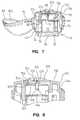
- FIG. 2is a perspective view, similar to FIG. 1 , except rotated 90 degrees, showing the cap in its closed position;
- FIG. 3is a rear elevational view of the present invention.
- FIG. 4is a front elevational view of the present invention.
- FIG. 5is a bottom plan view of the present invention.
- FIG. 6is an exploded view of the present invention.
- FIG. 7is a sectional view taken along lines 7 - 7 of FIG. 1 ;
- FIG. 8is an enlarged sectional view of a portion of the support member
- FIG. 9Ais a sectional view, similar to FIG. 8 , except showing the lancet in the piercing position;
- FIG. 9Bis a partial, perspective view of the body part engaging surface showing the lancet extending there through in the piecing position;
- FIG. 9Cis an exploded view of the upper and lower members of the body part engaging surface of the present invention.
- FIG. 9Dis a partial view of the capillary member of the present invention.
- FIG. 10is a perspective and partly broken away view of the capillary and test member of the present invention.
- FIG. 11is a bottom view of the present invention showing the test member without any reactant product thereon;
- FIG. 12is a bottom plan view similar to FIG. 11 , except showing reactant product thereon;
- FIG. 13is a sectional view of the support member and body member, showing a lancet in a piercing position
- FIG. 14is a sectional view of the body member and support member showing the lancet in the partially retracted position
- FIG. 15is a sectional view of the body member and support member, showing the lancet in the fully retracted position
- FIG. 16is a perspective view of the body member showing a lancet in the storage and piercing position
- FIG. 17is a perspective view of the body member, highlighting the lancet resisting surface
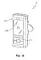
- FIG. 18is a front view of a cell phone-type meter that can be used with the testing device of the present invention.
- FIG. 19is a rear perspective view of the cell phone-type meter of the present invention showing the mounting member of the cell phone to which the testing device mounts;
- FIG. 20is an enlarged view of the mounting member of the meter
- FIG. 21is a rear perspective view showing the testing device mounted upon the cell phone-type meter of the present invention.
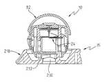
- FIG. 22is a sectional view of the device showing the body and support member in their respective first or “expanded” positions with respect to each other, and the lancet in its storage position;
- FIG. 23is a sectional view similar to FIG. 22 , except showing a testing device being coupled to a meter useable with the present invention
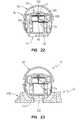
- FIG. 24is a sectional view similar to FIG. 22 , except showing the cap in the open position;
- FIG. 25is a view, similar to FIG. 24 , except showing the base, rotated approximately 60 degrees from the view shown in FIG. 24 ;
- FIG. 26is a view, similar to FIG. 25 ;
- FIG. 27is a view showing the lancet in its piercing position, with the body member and support member moved between the first (fully expanded) and second (fully compressed) positions, to reside in an intermediate position;
- FIG. 28is a sectional view, showing the lancet in the partially retracted position
- FIG. 29is a sectional view showing the lancet in the fully retracted position and the body member and support member in their second, or fully compressed positions;
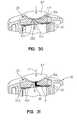
- FIG. 30is a sectional view showing the path of the blood flow, prior to the blood engaging the capillary mechanism of the present invention.
- FIG. 31is a view similar to FIG. 30 , showing the path of blood flow through the capillary member of the present invention.
- FIG. 32is a sectional view, similar to FIG. 31 ;
- FIG. 33is a sectional view showing the device mounted on to the meter of the present invention.
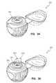
- FIG. 34is a perspective view of an alternate embodiment showing an alternate cleansing member
- FIG. 35is a perspective view of the embodiment of FIG. 34 , showing the cover peel strip of the cleansing member partially removed.
- FIG. 36is a sectional view of a second alternate embodiment, showing an alternate lance actuator.
- the testing device 10 of the present inventionis best shown and described initially with reference to FIGS. 1-8 .
- the primary components of the testing device 10include a body member 14 and a support member 18 .
- the support member 18is moveable with respect to the body member 14 between a first position ( FIG. 22 ) and a second position ( FIG. 29 ).
- a first positionFIG. 22
- a second positionFIG. 29
- the body member 14 and support member 18when assembled, they share generally a common axis, such that when in the first or expanded position, the body member 14 and support member 18 are moved relatively away from each other, so that the height of the testing device 10 is relatively maximized.
- the body member 14 and support member 18are moved axially toward each other so as to compress the testing device 10 , so that the height of the testing device is at its relative shortest.
- the support member 18includes a body part receiving surface 20 , for receiving a patient's body part.
- the testing device 10also includes a lancet 24 that is carried by the body member 14 , and is pivotably coupled to the body member 14 by the lancet 24 being coupled to a lancet support 26 .
- the lancetincludes a tip 27 that terminates in a point.
- a reagent containing test member 28 and calibration component 30are also provided.
- the lancetprior to the testing device being used, the lancet is normally positioned in a storage position ( FIG. 22 ) wherein the lancet tip 27 is disposed below the body part receiving surface 20 of the support member 18 .
- the lancet 24is moveable into a piercing position ( FIG. 27 ) wherein the tip 27 is disposed above the body part receiving surface 20 of the support.
- the lancet 24is also moveable into a retracted position ( FIG. 29 ) wherein the tip is disposed below the body part receiving surface 20 of the support member 18 .
- the lancet 24is moved into the retracted position through the engagement of the support member 18 with the lancet 24 as the support member 18 moves between its first (or expanded) position and its second (or compressed) position.
- the “movement” of the lancet 24 from its storage to its piercing positionactually occurs through the movement of the support member 18 relative to the generally stationary body member 14 and lancet 24 .
- the body member 14can best be understood with reference to FIG. 2 , 6 and 7 .
- the body member 14includes a base portion 34 that also serves as a coupler, for coupling the testing device 10 to a meter such as the cell phone type meter 35 shown in FIG. 18 .
- the base 34should have a generally planar lip, so that the base can be supported on a surface, such as a counter top.
- An aperture 34is formed on the underside of the base 34 , and is defined by an annular ring like member 38 , that also comprises a bayonet-type coupling, to permit the testing device to be coupled to the cell phone like meter 35 .
- a bayonet-type mountingprovides a quick coupling and release mechanism for coupling and uncoupling the testing device 10 to the cell phone meter 35 .
- the body member 14also includes a cylindrical perimetral base wall 42 that extends above, and has a slightly larger diameter than the base 34 .
- the body memberalso includes a cylindrical, axially extending tube 46 that is disposed centrally on the body member 14 .
- the cylindrical tube 46has an axially extending, radially outwardly facing exterior wall 48 , and an axially extending, radially inwardly facing interior wall 50 .
- Interior wall 50defines a hollow interior 52 that extends generally between aperture 38 , and the upper edge 53 of the cylindrical tube 46 .
- the body member 14also includes four, equi-distantly spaced support guide members 54 that are separated from each other at approximately 90 degrees.
- the upstanding support guide members 54extend axially, generally parallel to the axis of the body member 14 and are provided for receiving an interior surface of the support member, to appropriately position the support member 18 on the body member 14 , so that the support member 18 can move between its first or expanded position and its compressed position.
- the body memberalso includes a lancet support member 55 .
- Lancet support 55includes an angled upper surface that includes a groove 56 .
- Groove 56is sized and positioned for receiving the proximal leg 58 of the lancet 24 .
- groove 56is sized and positioned so that the proximal leg 58 can be snap-fit into groove 56 , so that leg 58 will be pivotably moveable within groove 56 , but still will be retained within groove 56 .
- the lancet 24( FIG. 6 ) includes a first end 64 that is disposed adjacent to the proximal leg 58 , and an intermediate, radially extending portion 66 .
- the radially extending portion 66is so named because, when the lancet 24 is in its storage position, the portion 66 will extend in a general radial direction.
- the name given this componentshould not be confined to specific directions, and that the claims should always be construed broadly enough to include devices wherein the various legs, such as legs 58 , 66 and 68 are disposed in other directions.
- the distal leg 68is also referred to herein as an axially extending leg or portion, because when the lancet 24 is in its rest or storage position, the portion 68 will generally extend axially, so that it can fit through the aperture 130 within the body part supporting surface. It should also be noted that when in the retracted position (of FIG. 15 ), the radially extending portion 66 of the lancet will actually extend in an axial direction, and the axially extending leg 68 will actually extend in a radial direction.
- the cylindrical tube 46does not comprise a totally endless cylinder. Rather, the cylinder 46 includes an axially extending slot 72 .
- the slotincludes an angled shelf 73 .
- the angled shelf 73along with axially extending wall 75 defines slot 72 , which together cooperate to form a lancet movement resistant surface for resisting pivotal movement of the lancet 24 .
- the lancet 66when in the storage position is positioned so that the radially extending leg 66 extends generally radially, and rests upon angled shelf 74 . Pivotal movement of the lancet 24 in a direction indicated generally by arrow L in FIG. 16 , causes the radially extending leg 66 to move through slot 72 .
- the use of the angled shelf 73 , and the spacing between the side walls 25 of the slot 72permits the lancet to move through the slot 72 , only by overcoming a predetermined amount of resistance, to thereby prevent the lancet 24 from free falling unimpededly through the slot 72 .
- This resistence in the movement of the lancet 24 that is induced by the slot 72helps to ensure that the lancet 24 will penetrate the skin of the user, and that the position of the lancet 24 with the tip 27 pointed upwardly will not be so weakly held so as to be unable to penetrate the skin.
- the support member 18has a cap 82 attached to it by a strip of plastic that comprises a living hinge 84 .
- the cap 82is able to move about the living hinge 84 from an open position, such as shown in FIG. 1 where the body part receiving surface 20 is exposed, and is exteriorly disposed, and a closed position, such as shown in FIGS. 2-4 . In the closed position, the cap 82 is disposed in a co-axial relationship with the support member 18 , so that the body part receiving surface 20 is captured interiorly within the interior of the cap 82 .
- the support member 18includes an axially extending, radially outwardly facing exterior wall 88 , that includes a knurled or ribbed surface 90 , for facilitating the user's ability to grasp the testing device 10 .
- the outer surface 88also includes a small concave portion 92 , that, when the cap 82 is in its closed position, the concave portion 92 is disposed adjacent to the overhanging lip 94 of the cap.
- the overhanging lip 94extends radially outwardly past the concave surface 92 , so that the user can place his finger under the lip 94 , to open the cap 82 .
- the upper edge of the knurled surface 90terminates in an axially facing, radially extending circumferential mating surface 96 , that is sized and positioned for mating with the axially facing, radially extending circumferential lip 98 of the cap 82 .
- the cap 82also includes a frusto-spherical exterior surface 104 that terminates at its lower end, at the axially facing circumferential lip 98 .
- the circumferential lip 98also includes an overhanging lip portion 94 , that is placeable in an opposed, and adjacent relation to the small concave surface 92 to form the opening handle.
- the cap 82includes a frusto-spherical interior wall 106 .
- a cleansing pad 108such as an alcohol soaked cleansing pad 108 is placed within the hollow interior defined by the interior wall 106 .
- the cleansing pad 108comes in handy, because the user should use the cleansing pad 108 to cleanse the skin adjacent of the body part that is to be lanced in order to draw blood from the user.
- the lance siteis cleansed before and after the site is lanced.
- the support member 18as best shown in FIGS. 1 , 6 , 7 and 9 B includes a testing assembly 118 , that includes the body part receiving surface 120 , and a radially outwardly first facing, axially extending side surface 114 .
- Axially extending side surface 114 and body part support surface 20are normally designed to be disposed interiorly, within the interior of cap 82 , when the device is in its closed position as is shown in FIG. 4 . However, when the cap 82 is opened, the body part receiving surface 20 and axially extending surface 114 become exteriorly disposed.
- the body part receiving surface 120includes several segments or parts, including a beveled, perimetral edge 117 , and a radially outwardly disposed ring-like portion 118 , that is disposed radially inwardly of the beveled perimetral edge.
- An elevated, mound-like annular lip 120is disposed radially interiorly of the radially outwardly disposed portion 118 , and comprises an endless ring.
- the elevated annular lip 120serves as a pressure cup, that is capable of exerting pressure against the skin of the user, when the user presses his finger against the elevated annular lip 120 so that the user's skin engages the surface of the elevated annular lip 120 .
- the pressure placed upon the userhelps to foster the flow of body fluid, and in particular, blood out of a lanced site.
- a first obtained advantageis that a smaller lanced “hole” in the user's skin can be used, because the pressure induced by the pressure cup can overcome the smallness of the hole, to still permit a sufficient amount of blood to flow out of the lanced hole, to enable the test to be performed properly.
- the use of the pressure cupenables the user to use a non-traditional lancing site.
- the finger tipsare the most typical place for a user to lance his skin to obtain blood for a blood test. Finger tips are chosen because of the high rate of blood flow through the finger tips.
- a forearm or other body part areahas an advantage over the fingers, because it is not as densely populated with nerves, and as such, lancing in a site such as the forearm will generally not hurt as much. Additionally, the forearm is not used for grabbing and holding objects, as are the finger tips. This lack of use by the forearm makes it less likely that the lanced site will be irritated or injured due to the activities performed by the body site.
- the elevated annular lip 120defines a recessed area that is disposed radially inwardly of the annular lip.
- a skin distancing memberthat includes a recessed dish 125 surrounded by a lip and platform 127 on which the body part can be placed.
- the skin distancing ring member 124is disposed concentrically with the pressure cup annular lip 120 .
- the skin distancing ring member 124is sized and positioned so as to maintain the body part, and preferably the skin of the body part at an appropriate position relative to the capillary portion of the device 10 . More particularly, the recessed annular skin distancing lip 127 and recess 125 help to keep the skin above the centrally disposed central aperture 130 , so that the user's skin does not plug (close) the aperture, which is the inlet to the capillary portion of the device 10 .
- a central aperture 130is centrally disposed within the body part engaging surface 20 , and is surrounded by a raised central dome 126 .
- the central apertureis sized and positioned for not only receiving blood flowing there through into the capillary portion of the device, but also to receive the tip 27 of the lancet 24 , so that the lancet tip 27 may penetrate the skin of the user, to cause blood to flow out of this punctured skin site.
- the body part supporting surface 20is preferably comprised of separately formed components, including an upper member 134 , and a lower member 136 .
- the primary purpose served by the upper member 134is to provide a body support surface upon which the user can place the body part such as a finger, or forearm that is to be lanced, so the blood can be drawn therefrom for testing.
- the upper member 134includes the pressure cup 120 and the skin distancing member 124 .
- the lower member 136serves the function primarily of serving as a test member support, and it contains the capillary mechanism and test member mechanism thereon.
- the upper member 134includes a radially outwardly facing cylindrical side wall 138 that is sized and positioned to be placed in an opposed relation, so that it is interiorly received by the radially inwardly facing side wall 140 of the lower member 136 .
- the lower member 136includes a centrally disposed axially extending capillary tower 144 .
- the central aperture 130that extends through the upper member 134 , actually opens downwardly in the tower 144 as a centrally disposed passageway, that includes a central portion 146 , and a radially outwardly disposed portion 148 .
- the centrally disposed portion 140comprises the channel through which the lancet passes through the upper 134 and lower 136 members, so that the tip 27 of the lancet can extend above the central dome 126 (see FIG. 9B ) so that it can pierce the skin of the user so that blood may flow from the lanced site.
- bloodflows through the central portion 146 in the radially outwardly disposed portion.
- the plasma component of the bloodstarts to become separated from the cellular components of the blood. This separation of the plasma from the cellular componments is a separation required for many blood assay tests, and that is described in more detail in the Kloepfer et al., patents, and published applications discussed above, and that are incorporated herein by reference.
- the tower 144is disposed within a centrally disposed well 152 that surrounds the tower 144 .
- the test member components 154include a radially extending capillary space 156 , that also serves as a suction chamber.
- the capillary space 156represents a space into which blood can flow so that the appropriate components of the blood (usually the plasma components) will be able to interact with the reagents contained on the reagent containing disk shaped test member disk 160 , that defines the lower wall that defines the capillary space 156 .
- a test member support 162that can also serve as a calibration component (See FIG. 6 ) is disposed below the reagent containing test member 160 .
- the test member 160can include one or a variety of reagents.
- test member reagentsthat can be employed to determine the presence, or either semi-quantitatively or quantitatively measure the amount of a particular component, or sets of components in a body fluid sample. Examples of reagents that can be placed on the test member to perform these tests can be found in patents held by the companies who manufacture such test member products, including Bayer, AG, and Roche Diagnostics.
- a foot member 166is placed at the base of the radially outwardly disposed portion 148 of the central channel 130 , ( FIG. 9D ) to provide a transition and guide to the blood flowing from the channel 148 , and into the capillary space 156 .
- a radially extending air vent channel 168extends between the base of tower 144 , and the radially outer edge 114 of the lower member 136 .
- the air vent channel 168provides an air vent to permit the flow of fluid radially outwardly in the capillary space 156 to proceed, without being hindered by air pressure considerations that would exist if no vent were present.
- the underside surface of the support member 18includes a downwardly opening cup member 172 , that is generally cylindrical in configuration, and includes a radially outwardly facing, axially extending outer wall surface 174 , and a radially inwardly facing axially extending inner wall surface 176 .
- the purpose of the wall surfaces of the cup member 172are to fit between the upstanding support guide member 54 of the body member, and the outer wall 48 of the cylinder 46 of the body member.
- the outer wall 174 of the inner cup 172is placed in an opposed relationship to the radially inwardly facing wall of the support member 54 , and the radially inwardly facing wall 176 of the support cup 172 is placed in an opposed adjacent relationship with the outer surface 48 of the cylindrical support tube 46 .
- the support cup 172 , support/guide member 54 and cylindrical tube 46are sized and positioned, so that the support cup 172 is slideably received by the body member, and is positioned so that the support member 18 and body member 14 are disposed generally coaxially with each other, and are positioned to be slideable with respect to each other, so that the support member 18 and body member 14 can move between an expanded and compressed position.
- the support cup 172also includes an axially outwardly facing, radially extending end surface 180 , that includes an adjuster member, that permits the user to adjust the distance that a tip 27 of the lancet 24 ( FIG. 9A ), is allowed to extend above the body surface 20 .
- the adjuster member 182comprises a series of five axially offset “step” surfaces, that are placed at a level different than the general surface 194 of the end surface 180 . As best shown in FIGS.
- the five axially offset surfaces 184 , 186 , 188 , 190 and 192are arranged in stair-step fashion, from the first axially offset surface 184 , which is the “highest” surface, to the lowest surface 194 which actually does not constitute a step, but rather, constitutes just a continuation of the remainder of the end surface. It will be appreciated that the height of the five axially offset surfaces 184 - 192 differs from the normal end surface 194 .
- the axial movement of the support member 18 relative to the body member 14causes the axially offset steps 184 - 194 to move downwardly, toward the radially extending arm 66 of the lancet 24 , when the lancet 24 is in its storage position.
- the lancet 24is in its storage position normally before the device is used to perform a test.
- the support member 18continues to move axially downwardly, it will reach a point where one of the axially offset steps 184 - 194 eventually engages the laterally extending arm 66 .
- the lancetis in a position similar to that shown in FIG. 27 where the tip 27 of the lancet 24 is disposed above the upper body part receiving surface 20 of the test member 10 . When the lancet tip 27 is in this position, it is capable of piercing the skin of the user.
- the usercan determine which of the various offset surfaces 184 - 194 is chosen to engage the radially extending leg 66 of the lancet 24 .
- This adjustmentis affected by rotating the support member 18 relative to the body member 14 about the shared axis A of the support member 18 and body member 14 .
- By rotating the support member 18one can position the desired offset surface 184 - 1 94 , above the lancet's 24 radially extending leg 66 , so that the desired surface 184 - 194 strikes the lancet's 24 radially extending leg 66 .
- the tip 27 of the lancet 24will extend a relatively greater distance above the body surface, and hence pierce the skin of the user to a greater distance or depth, than will occur if the user positions the support member so that the lancet leg 66 is engaged by the sixth or lowest offset surface 194 .
- the usercan determine the depth to which the lancet 24 tip 27 pierces the skin.
- the lancet 24pierces the skin to a sufficient depth to enable a sufficient amount of blood to flow out of the lanced site, so that enough blood is available for completing a test.
- the lancetshould penetrate the skin to the minimal depth necessary to achieve this blood flow, because by minimizing the depth, the user also tends to minimize the amount of pain that is associated with a lancet “stick”.
- the lancet tip 27By rotating the support member 18 so that it is positioned so that one of the intermediate surfaces 186 - 192 strikes the radially extending leg 66 of the lancet, the lancet tip 27 would be allowed to penetrate an intermediate distance somewhere between the relatively greater distance it would penetrate if the first step 184 were selected, and the relatively smaller and shorter depth that it would penetrate if the lowest offset surface 194 is chosen.
- the lancetis pivoted in a direction indicated generally by arrow R of FIG. 24 , on its pivotal connection with the lancet support 55 , to move downwardly and into the retracted position, such as is shown in FIGS. 28 and 29 .
- the radially inwardly facing surface 200 ( FIG. 24 ) of the exterior wall 88 of the support member 18engages and is placed in an opposed relationship with the cylindrical perimetral base wall 42 of the body member 14 , to further aid in properly positioning the support member 18 on the body member 14 , so that the body member can move axially relative to the body member 14 between the expanded and compressed positions.
- FIGS. 11 and 12are views through the bottom of the body member.
- the interior of the deviceis generally hollow, as is the base 34 .
- This hollownessenables one to look up the hollow interior, to see the reactant product that forms on the reactor area 205 of the test member 160 from the reaction between the reagents contained on the test member 160 and the body fluid that is placed thereon.
- the reaction between the reagents and the compound(s) of interest in the bloodwill form a colorometric reaction, wherein the reaction product produced is a colored reaction product, wherein the color bears some relationship either to the particular chemical of interest found on the test member, or otherwise, to the quantity of the particular chemical (e.g. glucose, cholesterol) of interest on the test member.
- Illustrated dots 202 shown in FIG. 12can be “calibration” dots that are placed on the calibration member 162 .
- the calibration dots 202can be pre-printed to replicate various colors, corresponding either to various compounds, or else, various quantities of compounds. These calibration dots 202 can also comprise a type of “bar code” that contains identifying information about the test device 10 .
- the colors formed by the reactant product colors from the reaction of the reagent and the test fluidare placed adjacent to the calibration color dots 202 , so that their color can be better compared, both by the meter, and by a visual check. By comparing the colors, one would likely get a more accurate and reproducible reading of the quantity of the test compound of interest formed by the interaction of the compound with the reagent on the test member 160 .
- the lancet 24when in the storage position, has its proximal end 68 pivotably coupled to lancet support member 55 , and has its radially extending leg 62 positioned to rest on the resistant shelf 73 of the cylinder 46 .
- the relative dimensions of the diameter of the lancet 24 , and the width of slot 72will cause the radially extending leg 66 of the lancet 24 to rest upon angled shelf 73 , and not move axially through slot 72 , unless some force is exerted on the lancet 24 to push it downwardly.
- slot 72The dimensions of slot 72 are chosen so that the amount of force required to push the radially extending leg 66 of the lancet through the slot 72 is a greater amount of force than is normally required to enable the tip 27 of the lancet 24 to penetrate the skin of the user. As such, the shelf 73 , wall 75 and slot 72 cooperate to provide enough resistence in the movement of leg 66 , so that the lancet tip 27 will pierce the skin before moving into its retracted position.
- the lancet 24is shown at a position, just prior to one of the axially offset surfaces 184 , engaging the radially extending leg 66 of the lancet.
- the support member 18still can move an additional distance downwardly, in a direction indicated by arrow A to “compress” the support member 18 and body member 14 .
- the tip 27 of the lancet 24lies just below the body part receiving surface 20 (and just below the inlet of capillary portion 130 ), and that further movement of the support member 18 in a direction indicated by arrow A, will cause the tip 27 of the lancet to extend above the surface 20 , so that it will be positioned above the body part engaging surface, similar to the position shown in FIG. 9B .
- FIG. 14it will be noted that the support member 18 has moved axially downwardly on the body portion 14 , when compared to the position shown in FIG. 13 .
- one of the axially offset surfaces 184has already engaged the radially extending leg 66 of the lancet 24 , and has caused the lancet 24 to pivot downwardly, to a position where the tip 27 is removed from aperture 130 .
- a support member 18is shown in its second or fully compressed position vis-a-vis body member 14 , so that the lancet 24 is in its fully retracted position, wherein the distal leg 68 of the lancet is generally disposed radially, and the tip 27 lies generally near the bottom of the body member 14 .
- the lancet 24is safely tucked interiorly of the body member 14 , in a position where it is highly unlikely to travel outside the testing device 10 , and therefore, is highly unlikely to be a in a position where it can accidentally stick the user, or another person.
- a meter 35 with which the testing device is designed to be usedis shown best in FIGS. 18-20 .
- the meter 35includes a case 206 that houses all of the internal components (not shown) of the meter 35 .
- the meter 35is shown as being a cell phone-type meter, that has dual functionality insofar as it can be used as a cell phone, and also as a test meter.
- One benefit of thisis that most cell phones contain a camera system already, that can be used to “read” colorometric reactions that occur on the reagent test member 160 of the device, and processing capabilities that can be exploited.
- the front of the cell phone/meter 35includes a screen 210 upon which information can be displayed, that preferably comprises a touch-type screen that also enables commands to be given through touching appropriate places on the screen 210 .
- a button-laiden control panel 212also appears on the front surface for permitting the user to enter commands to the cell phone/meter 35 .
- the rear of the cell phone/meter 35is shown as including a case member 216 , and a testing device receiver/coupler 218 .
- a series of depth indiciahere shown as 0 , 1 , 2 , 3 , 4 and 5 ( 222 ) are formed on the rear case member 216 , to indicate the depth at which the testing device has set the lancet 24 .
- Contained within the receiver/couplerare a variety of meter components.
- the meter components contained within the test receiverinclude a bayonet mounting surface 228 , for receiving the bayonet mount formed in the base 34 of the testing device 10 .
- One or more LEDs 232are provided for serving for as a light source, to light up in a controlled manner, the interior of the testing device 10 , adjacent to the test member 160 , so that enough light will be present to enable the meter or camera to perform its function.
- a switch 234is also operatively coupled in this area to detect the presence or absence of a testing device 10 on the receiver/coupler 218 .
- FIG. 21a testing device 10 is shown as being mounted, through the respective bayonet mounts, to the receiver/coupler 218 .
- the concave surface 92 of the support memberis placed opposite the “zero” indicia 222 . This placement of the concave surface 92 adjacent to the zero indicia, can indicate to the user that the lowest axially offset step 194 will be used so that the lancet 24 tip 27 will penetrate the skin, the smallest distance available by the unit.
- the concave member 92were pointing to indicia 5 , which would occur if the support member 18 were rotated about its axis, so that the concave surface 92 faced indicia 5 , it would indicate that the highest axially offset surface 184 of the adjuster was being employed, so that the lancet tip 27 would penetrate the greatest possible distance into the skin of the user. It will also be appreciated that if the user desired to set the lancet tip 27 depth at an intermediate level, he would cause the center of the concave surface 92 to point to one of the intermediate indicia, such as 1 , 2 , 3 or 4 .
- the usercan place his finger over the body part receiving surface 20 to begin the testing procedure.
- FIGS. 22-28depict the sequence that the lancet goes through, in moving from its storage to its retracted position.
- FIG. 22a sectional view of the device is shown.
- the lancet 24has its radially extending leg 66 disposed in a radially extending direction, and that the tip 27 of the lancet is disposed below the body part receiving surface 20 , and below the tip of the inlet 130 of the capillary portion.
- the axially offset surfaces 184 , 186 , 188are above, and have not yet engaged the lancet 24 .
- FIG. 23shows a view similar to FIG. 22 , with the exception that the device 10 is shown as being coupled to the receiver/coupler 218 of cell phone/meter 35 .
- FIGS. 24 and 25also show the device in the storage position, similar to FIGS. 22 , except that FIG. 24 shows the cap 82 in an open position, and FIG. 25 shows the device rotated about 45 degrees about its axis, from the position shown in FIGS. 22 , 23 and 24 .
- FIG. 26shows a view generally similar to FIG. 25
- FIG. 27shows a view, wherein the support member 18 has moved in an axially compressed direction, which direction is indicated generally by arrow A.
- FIG. 27shows the device 10 wherein the lancet 24 is in the piercing position, as it will be noted that the tip 27 of the lancet 24 is extending above the body part receiving surface 20 , and in fact, the tip 27 of the lancet 24 is about at the same level as the lip of the pressure receiving cup 120 , and is above the level of the lip 127 of the skin distancing member 124 .
- the lancet engaging axially offset step 184is just about to engage the radially extending leg 66 of the lancet. This contrasts from the view of FIG. 26 where it will be noticed that the lancet engaging surface 184 is positioned above the radially extending leg 66 of the lancet.
- FIG. 28shows the lancet 24 after it has begun moving toward its retracted position. It will be noted that tip 27 of the lancet 24 is completely removed from the capillary channel 130 , and the lancet engaging surface 184 is positioned below the pivot point (leg) 58 of the lancet 24 .
- FIG. 29shows the lancet 24 in the fully retracted position wherein the radially extending leg 66 of the lancet extends in a generally axially direction.
- FIGS. 31 and 32illustrate the sequence of events that occurs relating to the capillary channel during the use of the testing device 10 .
- a body part BPis shown as being placed in FIG. 30 on the body part receiving surface 20 .
- the skin of the fingersstraddles the lip 127 of the body distancing member 124 , with the recess 125 of the body distancing member providing enough space so that the finger does not plug the inlet opening 238 of the capillary channel 130 .
- FIG. 1the arrow Z shows pressure being exerted downwardly on the body part supporting surface 20 .
- This pressureis the pressure that will cause the support member 18 to compress the testing device 110 , and cause the lancet tip 27 to travel to its piercing position.
- FIG. 31assumes that the piercing has already occurred, and that a body fluid BF such as blood has begun to run out of the body part finger BP, and has begun flowing axially into the capillary channel 130 , and radially outwardly, in the capillary space 156 that is above the test member 160 .
- suction area 156is pinched off at pinch point P against the testing disk 160 .
- Pinch point Ppinches off the capillary channel/suction area 156 , due to the force that is exerted by the finger, that causes the peripheral area 242 of the body part supporting surface to press downwardly on the test disk 160 to cause the test disk 160 to bend, to thereby form the pinch point P.
- FIG. 32arrow Z shows that the pressure of the body part has been lifted off the body part receiving surface 20 .
- This removal of force from the body part receiving member 20enables the test disk 160 to straighten out, which enables the capillary channel 156 to leave its pinch point.
- This removal of the pinch pointwhen coupled with the venting achieved by the vent channel 168 ( FIG. 10 ), fosters capillarity, and fosters the radially outward movement of the body fluid BF.
- the reaction capillary compartment 161contains the body fluid that has reacted with the reagent, to form the reactant product.
- This reaction capillary compartment 161is the area in which the meter focuses its attention (e.g. the camera takes its picture) to obtain a reading of the test disk. It will be noticed that he main bolus of excess blood BF has traveled downstream of the reaction capillary compartment to the excess blood capillary compartment 165
- Capillarityis fostered because air is drawn into the capillary chamber, that brings oxygen into the chamber 156 , which is necessary for some of the reagent/plasma reactions to occur, along with fostering the flow of blood radially outwardly. Additionally, there exists a capillary force differential between the reaction capillary compartment 161 and the excess blood capillary compartment 165 which also fosters separation and capillarity. Capillarity is further enhanced due to the positioning and height differential between the inlet to the capillary channel 130 at the top of tower 144 , and the relatively lower position of the test disk 160 that contains both the reaction capillary compartment 161 and the excess blood capillary compartment 165 .
- FIG. 33presents another sectional view of the testing device 10 , after the test is finished. After the testing is finished, the cap 82 is placed in its closed position, and the lens 230 , can view the test results contained on the test member 160 .
- FIGS. 34 and 35disclose an alternate embodiment testing device 300 .
- Testing device 300is generally identical to testing device 10 shown in FIGS. 1-33 , with the exception of the fact that testing device 300 includes a cleansing member 302 that is placed upon the body part supporting surface 20 .
- the cleansing member 302is generally ring-shaped, and includes a ring-shaped cleansing swab 304 that is disposed concentrically with and radially outwardly of the pressure cup 310 .
- a cover member 306covers the cleansing swab and includes a pull tab 308 to facilitate the user removing the cover member 306 .
- Cleansing swab 304should preferably be fixedly coupled, such as by glue, to the testing device, or else, snugly fitted within a channel. Normally, it will be expected that cleansing swab will contain some sort of disinfectant, such as alcohol for which the user can cleanse his skin both prior to and after his body part is lanced.
- disinfectantsuch as alcohol for which the user can cleanse his skin both prior to and after his body part is lanced.
- FIG. 36shows an alternate embodiment test device 400 wherein the lancet movement mechanism shown in FIGS. 1-35 is replaced by a spring-loaded lancet movement system.
- the lancet movement systemincludes a lancet moving spring 402 that is provided for engaging a platform 403 that supports lancet 405 .
- This spring 402expands to move platform 403 upwardly, to thereby move lancet 408 upwardly through the capillary channel 411 , and into engagement with the user's body part.
- a lancet retraction spring 404is provided for acting against the force exerted by the lancet moving spring 402 to cause the lancet 405 to retract downwardly, and back beneath the body part engaging surface 415 , after the lancet pierces the skin of the user.
- a release member 406is positioned to be engaged with one of several axially offset surfaces, e.g. 408 , 410 that are designed and configured similarly to the axial offset surfaces discussed above in connection with FIGS. 1-33 .
- the axially offset surfacesenable the user to adjust the depth to which the lancet 405 will penetrate their skin.
- the spring 402is then released to urge the lancet 405 upwardly and into engagement with the body part.
Landscapes
- Health & Medical Sciences (AREA)
- Life Sciences & Earth Sciences (AREA)
- Engineering & Computer Science (AREA)
- Physics & Mathematics (AREA)
- Biomedical Technology (AREA)
- Molecular Biology (AREA)
- Hematology (AREA)
- Biophysics (AREA)
- Pathology (AREA)
- General Health & Medical Sciences (AREA)
- Public Health (AREA)
- Surgery (AREA)
- Animal Behavior & Ethology (AREA)
- Medical Informatics (AREA)
- Heart & Thoracic Surgery (AREA)
- Veterinary Medicine (AREA)
- Dermatology (AREA)
- Chemical & Material Sciences (AREA)
- Manufacturing & Machinery (AREA)
- Ecology (AREA)
- Optics & Photonics (AREA)
- Emergency Medicine (AREA)
- Urology & Nephrology (AREA)
- Pain & Pain Management (AREA)
- Food Science & Technology (AREA)
- Medicinal Chemistry (AREA)
- Analytical Chemistry (AREA)
- Biochemistry (AREA)
- General Physics & Mathematics (AREA)
- Immunology (AREA)
- Measurement Of The Respiration, Hearing Ability, Form, And Blood Characteristics Of Living Organisms (AREA)
Abstract
Description
Claims (41)
Priority Applications (4)
| Application Number | Priority Date | Filing Date | Title |
|---|---|---|---|
| US11/832,475US7846110B2 (en) | 2006-08-03 | 2007-08-01 | Self-contained test unit for testing body fluids |
| PCT/US2007/017211WO2008019028A2 (en) | 2006-08-03 | 2007-08-02 | Self-contained test unit for testing body fluids |
| EP07836417.1AEP2068698B1 (en) | 2006-08-03 | 2007-08-02 | Self-contained test unit for testing body fluids |
| CA2657511ACA2657511C (en) | 2006-08-03 | 2007-08-02 | Self-contained test unit for testing body fluids |
Applications Claiming Priority (2)
| Application Number | Priority Date | Filing Date | Title |
|---|---|---|---|
| US83532506P | 2006-08-03 | 2006-08-03 | |
| US11/832,475US7846110B2 (en) | 2006-08-03 | 2007-08-01 | Self-contained test unit for testing body fluids |
Publications (2)
| Publication Number | Publication Date |
|---|---|
| US20080033319A1 US20080033319A1 (en) | 2008-02-07 |
| US7846110B2true US7846110B2 (en) | 2010-12-07 |
Family
ID=39030136
Family Applications (1)
| Application Number | Title | Priority Date | Filing Date |
|---|---|---|---|
| US11/832,475ActiveUS7846110B2 (en) | 2006-08-03 | 2007-08-01 | Self-contained test unit for testing body fluids |
Country Status (4)
| Country | Link |
|---|---|
| US (1) | US7846110B2 (en) |
| EP (1) | EP2068698B1 (en) |
| CA (1) | CA2657511C (en) |
| WO (1) | WO2008019028A2 (en) |
Cited By (12)
| Publication number | Priority date | Publication date | Assignee | Title |
|---|---|---|---|---|
| WO2014096001A3 (en)* | 2012-12-19 | 2014-08-14 | 4A Medicom Gmbh | Body fluid guiding capillary structure for self-contained test unit |
| USD711541S1 (en)* | 2013-01-15 | 2014-08-19 | 4A Medicom Gmbh | Body fluid testing device |
| USD716453S1 (en)* | 2013-01-15 | 2014-10-28 | 4A Medicom Gmbh | Body fluid testing device |
| WO2014174096A1 (en)* | 2013-04-26 | 2014-10-30 | 4A Medicom Gmbh | Individually packaged disposable blood testing unit |
| US9237866B2 (en) | 2013-04-29 | 2016-01-19 | Birch Narrows Development, LLC | Blood glucose management |
| GB2532220A (en)* | 2014-11-11 | 2016-05-18 | 4A Medicom Gmbh | Self-contained storage unit for storing body fluid |
| US9380970B2 (en) | 2011-02-05 | 2016-07-05 | Pops! Diabetes Care, Inc. | Lancet device with flexible cover |
| US11033212B2 (en) | 2014-08-01 | 2021-06-15 | Tasso, Inc. | Devices, systems and methods for gravity-enhanced microfluidic collection, handling and transferring of fluids |
| US11395614B2 (en) | 2012-01-25 | 2022-07-26 | Tasso, Inc. | Methods, systems, and devices relating to open microfluidic channels |
| US11510659B2 (en) | 2018-09-14 | 2022-11-29 | Tasso, Inc. | Bodily fluid collection devices and related methods |
| US11633136B2 (en) | 2021-02-26 | 2023-04-25 | Tasso, Inc. | Bodily fluid collection devices and related methods |
| US11642057B2 (en) | 2015-12-21 | 2023-05-09 | Tasso, Inc. | Devices, systems and methods for actuation and retraction in fluid collection |
Families Citing this family (66)
| Publication number | Priority date | Publication date | Assignee | Title |
|---|---|---|---|---|
| US6391005B1 (en) | 1998-03-30 | 2002-05-21 | Agilent Technologies, Inc. | Apparatus and method for penetration with shaft having a sensor for sensing penetration depth |
| US8641644B2 (en) | 2000-11-21 | 2014-02-04 | Sanofi-Aventis Deutschland Gmbh | Blood testing apparatus having a rotatable cartridge with multiple lancing elements and testing means |
| US7344507B2 (en) | 2002-04-19 | 2008-03-18 | Pelikan Technologies, Inc. | Method and apparatus for lancet actuation |
| US9226699B2 (en) | 2002-04-19 | 2016-01-05 | Sanofi-Aventis Deutschland Gmbh | Body fluid sampling module with a continuous compression tissue interface surface |
| US7041068B2 (en) | 2001-06-12 | 2006-05-09 | Pelikan Technologies, Inc. | Sampling module device and method |
| US7749174B2 (en) | 2001-06-12 | 2010-07-06 | Pelikan Technologies, Inc. | Method and apparatus for lancet launching device intergrated onto a blood-sampling cartridge |
| US9795747B2 (en) | 2010-06-02 | 2017-10-24 | Sanofi-Aventis Deutschland Gmbh | Methods and apparatus for lancet actuation |
| JP4209767B2 (en) | 2001-06-12 | 2009-01-14 | ペリカン テクノロジーズ インコーポレイテッド | Self-optimized cutting instrument with adaptive means for temporary changes in skin properties |
| US7981056B2 (en) | 2002-04-19 | 2011-07-19 | Pelikan Technologies, Inc. | Methods and apparatus for lancet actuation |
| EP1395185B1 (en) | 2001-06-12 | 2010-10-27 | Pelikan Technologies Inc. | Electric lancet actuator |
| US9427532B2 (en) | 2001-06-12 | 2016-08-30 | Sanofi-Aventis Deutschland Gmbh | Tissue penetration device |
| US8337419B2 (en) | 2002-04-19 | 2012-12-25 | Sanofi-Aventis Deutschland Gmbh | Tissue penetration device |
| US8372016B2 (en) | 2002-04-19 | 2013-02-12 | Sanofi-Aventis Deutschland Gmbh | Method and apparatus for body fluid sampling and analyte sensing |
| US8579831B2 (en) | 2002-04-19 | 2013-11-12 | Sanofi-Aventis Deutschland Gmbh | Method and apparatus for penetrating tissue |
| US7297122B2 (en) | 2002-04-19 | 2007-11-20 | Pelikan Technologies, Inc. | Method and apparatus for penetrating tissue |
| US7331931B2 (en) | 2002-04-19 | 2008-02-19 | Pelikan Technologies, Inc. | Method and apparatus for penetrating tissue |
| US7708701B2 (en) | 2002-04-19 | 2010-05-04 | Pelikan Technologies, Inc. | Method and apparatus for a multi-use body fluid sampling device |
| US7491178B2 (en) | 2002-04-19 | 2009-02-17 | Pelikan Technologies, Inc. | Method and apparatus for penetrating tissue |
| US9795334B2 (en) | 2002-04-19 | 2017-10-24 | Sanofi-Aventis Deutschland Gmbh | Method and apparatus for penetrating tissue |
| US7547287B2 (en) | 2002-04-19 | 2009-06-16 | Pelikan Technologies, Inc. | Method and apparatus for penetrating tissue |
| US9248267B2 (en) | 2002-04-19 | 2016-02-02 | Sanofi-Aventis Deustchland Gmbh | Tissue penetration device |
| US9314194B2 (en) | 2002-04-19 | 2016-04-19 | Sanofi-Aventis Deutschland Gmbh | Tissue penetration device |
| US8267870B2 (en) | 2002-04-19 | 2012-09-18 | Sanofi-Aventis Deutschland Gmbh | Method and apparatus for body fluid sampling with hybrid actuation |
| US7674232B2 (en) | 2002-04-19 | 2010-03-09 | Pelikan Technologies, Inc. | Method and apparatus for penetrating tissue |
| US8784335B2 (en) | 2002-04-19 | 2014-07-22 | Sanofi-Aventis Deutschland Gmbh | Body fluid sampling device with a capacitive sensor |
| US7976476B2 (en) | 2002-04-19 | 2011-07-12 | Pelikan Technologies, Inc. | Device and method for variable speed lancet |
| US7892183B2 (en) | 2002-04-19 | 2011-02-22 | Pelikan Technologies, Inc. | Method and apparatus for body fluid sampling and analyte sensing |
| US8221334B2 (en) | 2002-04-19 | 2012-07-17 | Sanofi-Aventis Deutschland Gmbh | Method and apparatus for penetrating tissue |
| US8360992B2 (en) | 2002-04-19 | 2013-01-29 | Sanofi-Aventis Deutschland Gmbh | Method and apparatus for penetrating tissue |
| US7229458B2 (en) | 2002-04-19 | 2007-06-12 | Pelikan Technologies, Inc. | Method and apparatus for penetrating tissue |
| US7232451B2 (en) | 2002-04-19 | 2007-06-19 | Pelikan Technologies, Inc. | Method and apparatus for penetrating tissue |
| US7901362B2 (en) | 2002-04-19 | 2011-03-08 | Pelikan Technologies, Inc. | Method and apparatus for penetrating tissue |
| US8702624B2 (en) | 2006-09-29 | 2014-04-22 | Sanofi-Aventis Deutschland Gmbh | Analyte measurement device with a single shot actuator |
| US7909778B2 (en) | 2002-04-19 | 2011-03-22 | Pelikan Technologies, Inc. | Method and apparatus for penetrating tissue |
| US8574895B2 (en) | 2002-12-30 | 2013-11-05 | Sanofi-Aventis Deutschland Gmbh | Method and apparatus using optical techniques to measure analyte levels |
| DE602004028463D1 (en) | 2003-05-30 | 2010-09-16 | Pelikan Technologies Inc | METHOD AND DEVICE FOR INJECTING LIQUID |
| US7850621B2 (en) | 2003-06-06 | 2010-12-14 | Pelikan Technologies, Inc. | Method and apparatus for body fluid sampling and analyte sensing |
| WO2006001797A1 (en) | 2004-06-14 | 2006-01-05 | Pelikan Technologies, Inc. | Low pain penetrating |
| US8282576B2 (en) | 2003-09-29 | 2012-10-09 | Sanofi-Aventis Deutschland Gmbh | Method and apparatus for an improved sample capture device |
| EP1680014A4 (en) | 2003-10-14 | 2009-01-21 | Pelikan Technologies Inc | METHOD AND DEVICE FOR A VARIABLE USER INTERFACE |
| US7822454B1 (en) | 2005-01-03 | 2010-10-26 | Pelikan Technologies, Inc. | Fluid sampling device with improved analyte detecting member configuration |
| US8668656B2 (en) | 2003-12-31 | 2014-03-11 | Sanofi-Aventis Deutschland Gmbh | Method and apparatus for improving fluidic flow and sample capture |
| WO2006011062A2 (en) | 2004-05-20 | 2006-02-02 | Albatros Technologies Gmbh & Co. Kg | Printable hydrogel for biosensors |
| US9775553B2 (en) | 2004-06-03 | 2017-10-03 | Sanofi-Aventis Deutschland Gmbh | Method and apparatus for a fluid sampling device |
| WO2005120365A1 (en) | 2004-06-03 | 2005-12-22 | Pelikan Technologies, Inc. | Method and apparatus for a fluid sampling device |
| US8652831B2 (en)* | 2004-12-30 | 2014-02-18 | Sanofi-Aventis Deutschland Gmbh | Method and apparatus for analyte measurement test time |
| US20090054811A1 (en)* | 2004-12-30 | 2009-02-26 | Dirk Boecker | Method and apparatus for analyte measurement test time |
| KR20090031763A (en)* | 2006-07-06 | 2009-03-27 | 라피딕스 리미티드. | Integrated blood sampling and testing device and method |
| WO2009081405A2 (en)* | 2007-12-25 | 2009-07-02 | Rapidx Ltd. | Devices and methods for reduced-pain blood sampling |
| EP2265324B1 (en) | 2008-04-11 | 2015-01-28 | Sanofi-Aventis Deutschland GmbH | Integrated analyte measurement system |
| US9375169B2 (en) | 2009-01-30 | 2016-06-28 | Sanofi-Aventis Deutschland Gmbh | Cam drive for managing disposable penetrating member actions with a single motor and motor and control system |
| US20100256524A1 (en) | 2009-03-02 | 2010-10-07 | Seventh Sense Biosystems, Inc. | Techniques and devices associated with blood sampling |
| US8965476B2 (en) | 2010-04-16 | 2015-02-24 | Sanofi-Aventis Deutschland Gmbh | Tissue penetration device |
| EP2745778B1 (en)* | 2010-06-24 | 2018-10-03 | Rapidx Ltd. | Device for blood sampling |
| US20130158482A1 (en) | 2010-07-26 | 2013-06-20 | Seventh Sense Biosystems, Inc. | Rapid delivery and/or receiving of fluids |
| WO2012021801A2 (en) | 2010-08-13 | 2012-02-16 | Seventh Sense Biosystems, Inc. | Systems and techniques for monitoring subjects |
| ES2550668T3 (en)* | 2010-08-13 | 2015-11-11 | Seventh Sense Biosystems, Inc. | Clinical and / or consumer techniques and devices |
| WO2012064802A1 (en) | 2010-11-09 | 2012-05-18 | Seventh Sense Biosystems, Inc. | Systems and interfaces for blood sampling |
| WO2012149155A1 (en) | 2011-04-29 | 2012-11-01 | Seventh Sense Biosystems, Inc. | Systems and methods for collecting fluid from a subject |
| US20130158468A1 (en) | 2011-12-19 | 2013-06-20 | Seventh Sense Biosystems, Inc. | Delivering and/or receiving material with respect to a subject surface |
| KR102013466B1 (en) | 2011-04-29 | 2019-08-22 | 세븐쓰 센스 바이오시스템즈, 인크. | Delivering and/or receiving fluids |
| CN103874461B (en) | 2011-04-29 | 2017-05-10 | 第七感生物系统有限公司 | Devices for collecting and/or manipulating blood spots or other bodily fluids |
| CN104080403A (en)* | 2011-11-25 | 2014-10-01 | 赛诺菲-安万特德国有限公司 | Apparatus for eliciting blood sample |
| USD770636S1 (en)* | 2014-09-17 | 2016-11-01 | Assure Tech.(Hangzhou) Co., Ltd. | Detection device for medical purposes |
| USD836209S1 (en)* | 2015-01-16 | 2018-12-18 | Assure Tech. (Hangzhou) Co., Ltd. | Detection device for medical purposes |
| CN205280728U (en)* | 2015-12-31 | 2016-06-01 | 深圳市贝沃德克生物技术研究院有限公司 | Serum mark detecting system |
Citations (63)
| Publication number | Priority date | Publication date | Assignee | Title |
|---|---|---|---|---|
| US3760809A (en)* | 1971-10-22 | 1973-09-25 | Damon Corp | Surgical lancet having casing |
| US4230118A (en)* | 1977-08-05 | 1980-10-28 | Holman Rury R | Automatic lancet |
| US4414975A (en)* | 1981-05-15 | 1983-11-15 | Ryder International Corp. | Blood lancet |
| US4539988A (en)* | 1983-07-05 | 1985-09-10 | Packaging Corporation International | Disposable automatic lancet |
| US4628929A (en)* | 1985-08-16 | 1986-12-16 | American Hospital Supply Corporation | Retractable blade bleeding time device |
| US4643189A (en)* | 1985-02-19 | 1987-02-17 | W. T. Associates | Apparatus for implementing a standardized skin incision |
| US4715374A (en)* | 1986-11-14 | 1987-12-29 | Medicore, Inc. | Disposable automatic lancet |
| US4844095A (en)* | 1987-12-14 | 1989-07-04 | Medicore, Inc. | Automatic lancet device |
| US4983178A (en)* | 1988-11-14 | 1991-01-08 | Invictus, Inc. | Lancing device |
| US5212879A (en)* | 1991-05-15 | 1993-05-25 | International Technidyne Corp. | Method for manufacturing a disposable-retractable finger stick device |
| US5314441A (en)* | 1992-10-16 | 1994-05-24 | International Technidyne Corporation | Disposable slicing lancet assembly |
| US5630828A (en)* | 1996-04-17 | 1997-05-20 | International Techndyne Corporation | Low cost disposable lancet |
| US5645555A (en)* | 1994-07-27 | 1997-07-08 | Ryder International Corporation | Rotary lancet |
| US5797940A (en)* | 1997-05-30 | 1998-08-25 | International Technidyne Corporation | Adjustable skin incision device |
| US5851215A (en)* | 1996-09-24 | 1998-12-22 | International Technidyne Corporation | Low cost disposable lancet |
| US5891053A (en)* | 1995-05-25 | 1999-04-06 | Kabushiki Kaisya Advance | Blood-collecting device |
| US5951492A (en)* | 1996-05-17 | 1999-09-14 | Mercury Diagnostics, Inc. | Methods and apparatus for sampling and analyzing body fluid |
| US5951582A (en)* | 1998-05-22 | 1999-09-14 | Specialized Health Products, Inc. | Lancet apparatus and methods |
| US5962215A (en)* | 1996-04-05 | 1999-10-05 | Mercury Diagnostics, Inc. | Methods for testing the concentration of an analyte in a body fluid |
| US6042595A (en)* | 1999-03-02 | 2000-03-28 | Apls Co., Ltd. | Lancet apparatus for producing a precisely controlled incision |
| US6132449A (en) | 1999-03-08 | 2000-10-17 | Agilent Technologies, Inc. | Extraction and transportation of blood for analysis |
| US6221089B1 (en)* | 1997-07-07 | 2001-04-24 | International Technidyne Corporation | Skin incision device with compression spring assembly |
| US6358265B1 (en)* | 2000-07-18 | 2002-03-19 | Specialized Health Products, Inc. | Single-step disposable safety lancet apparatus and methods |
| EP1202057A2 (en) | 2000-10-25 | 2002-05-02 | Micronix, Inc. | Solid state microcuvette using dry films |
| US20020177761A1 (en)* | 2001-04-26 | 2002-11-28 | Phoenix Bioscience | Integrated lancing and analytic device |
| US20020177788A1 (en)* | 2000-03-27 | 2002-11-28 | Alastair Hodges | Method and device for sampling and analyzing interstitial fluid and whole blood samples |
| US6535112B1 (en)* | 1999-05-11 | 2003-03-18 | Robert Bosch Gmbh | Diagnostic test device for motor vehicles which comprises a portable testing apparatus |
| US20030093010A1 (en)* | 2001-11-15 | 2003-05-15 | Matthias Essenpreis | Fluid sampling apparatus |
| US20030109777A1 (en)* | 2001-12-07 | 2003-06-12 | Kloepfer Hans G. | Consolidated body fluid testing device and method |
| US20040028558A1 (en) | 2002-08-12 | 2004-02-12 | Bayer Corporation | Fluid collecting and monitoring device |
| US6696240B1 (en) | 1999-10-26 | 2004-02-24 | Micronix, Inc. | Capillary test strip to separate particulates |
| US20040138588A1 (en)* | 2002-11-06 | 2004-07-15 | Saikley Charles R | Automatic biological analyte testing meter with integrated lancing device and methods of use |
| US6808499B1 (en)* | 2000-09-29 | 2004-10-26 | University Of Vermont | Therapeutic and diagnostic needling device and method |
| US20040225312A1 (en)* | 2003-05-09 | 2004-11-11 | Phoenix Bioscience | Linearly lancing integrated pivot disposable |
| US20040236251A1 (en)* | 2002-12-27 | 2004-11-25 | Roe Steven N. | Precision depth control lancing tip |
| US20040267229A1 (en)* | 2001-08-16 | 2004-12-30 | Piet Moerman | In-situ adapter for a testing device |
| US20040267300A1 (en)* | 2003-06-27 | 2004-12-30 | Mace Chad Harold | Lancing device |
| US6849052B2 (en)* | 1999-12-13 | 2005-02-01 | Arkray, Inc. | Body fluid measuring apparatus with lancet and lancet holder used for the measuring apparatus |
| US20050033196A1 (en)* | 2001-11-27 | 2005-02-10 | Yoram Alroy | Device for sampling blood droplets under vacuum conditions |
| US20050033341A1 (en)* | 2003-07-28 | 2005-02-10 | Vreeke Mark S. | Swing lance with integrated sensor |
| US20050065414A1 (en) | 2003-07-24 | 2005-03-24 | Allen Robert V. | Pulse oximeter system |
| US20050096565A1 (en)* | 2003-10-31 | 2005-05-05 | Yu-Hong Chang | Compact structure of a new biosensor monitor |
| US20050154410A1 (en)* | 2003-11-12 | 2005-07-14 | Conway William E. | Lancing device and multi-lancet cartridge |
| US20050228313A1 (en)* | 2003-12-04 | 2005-10-13 | University Technologies International Inc. | Fluid sampling, analysis and delivery system |
| EP1625823A2 (en) | 2004-08-11 | 2006-02-15 | Micronix, Inc. | Methods and apparatus for analysing a fluid |
| US20060072004A1 (en) | 2003-12-17 | 2006-04-06 | Canon Kabushiki Kaisha | Communication device and control method |
| US20060100543A1 (en)* | 2002-12-30 | 2006-05-11 | Raney Charles C | Integrated Analytical Test Element |
| US7052652B2 (en) | 2003-03-24 | 2006-05-30 | Rosedale Medical, Inc. | Analyte concentration detection devices and methods |
| US20060222567A1 (en) | 2005-04-01 | 2006-10-05 | Hafellner | Body fluid testing component for simultaneous analyte detection |
| US20060229532A1 (en)* | 2005-04-12 | 2006-10-12 | Daniel Wong | Integrated lancing test strip with retractable lancet |
| US20060264778A1 (en)* | 2005-05-19 | 2006-11-23 | Vasogen Ireland Limited | Verification method and system for medical treatment |
| US20060264997A1 (en)* | 2005-04-07 | 2006-11-23 | Robert Colonna | Finger activated lancet device |
| US7150755B2 (en)* | 2002-02-21 | 2006-12-19 | Facet Technologies, Llc | Blood sampling device |
| US20060292039A1 (en) | 2003-09-05 | 2006-12-28 | Kazuhiro Iida | Measuring system |
| US20070015198A1 (en) | 2000-01-15 | 2007-01-18 | Avigenics, Inc. | DNA sequence detection of nucleated red blood cells |
| US7235056B2 (en)* | 1996-05-17 | 2007-06-26 | Amira Medical | Body fluid sampling device and methods of use |
| US20070233395A1 (en)* | 2006-04-03 | 2007-10-04 | Home Diagnostics, Inc. | Diagnostic meter |
| US20070233166A1 (en)* | 2004-05-27 | 2007-10-04 | Facet Technologies, Llc | Low-Cost Lancing Device with Cantilevered Leaf Spring for Launch and Return |
| US7299081B2 (en)* | 2004-06-15 | 2007-11-20 | Abbott Laboratories | Analyte test device |
| US20080009766A1 (en)* | 2005-05-09 | 2008-01-10 | Holmes Elizabeth A | Systems and methods for improving medical treatments |
| US7374959B2 (en) | 2004-03-31 | 2008-05-20 | Samsung Electro-Mechanics Co., Ltd. | Two-wavelength semiconductor laser device and method of manufacturing the same |
| US20080208077A1 (en)* | 2004-05-21 | 2008-08-28 | Iddan Gavriel J | Device, System and Method for In-Vivo Sampling |
| US7452365B2 (en)* | 2003-07-28 | 2008-11-18 | Helena Laboratories | Load-controlled device for a patterned skin incision of constant depth |
Family Cites Families (5)
| Publication number | Priority date | Publication date | Assignee | Title |
|---|---|---|---|---|
| US5279294A (en)* | 1985-04-08 | 1994-01-18 | Cascade Medical, Inc. | Medical diagnostic system |
| US6700251B2 (en) | 2001-11-06 | 2004-03-02 | Citizen Electronics Co., Ltd. | Vibrating device for axially vibrating a movable member |
| GB2388898B (en)* | 2002-04-02 | 2005-10-05 | Inverness Medical Ltd | Integrated sample testing meter |
| US7374949B2 (en)* | 2003-05-29 | 2008-05-20 | Bayer Healthcare Llc | Diagnostic test strip for collecting and detecting an analyte in a fluid sample |
| EP1737345A1 (en)* | 2004-04-15 | 2007-01-03 | Roche Diagnostics GmbH | Integrated spot monitoring device with fluid sensor |
- 2007
- 2007-08-01USUS11/832,475patent/US7846110B2/enactiveActive
- 2007-08-02CACA2657511Apatent/CA2657511C/enactiveActive
- 2007-08-02EPEP07836417.1Apatent/EP2068698B1/ennot_activeNot-in-force
- 2007-08-02WOPCT/US2007/017211patent/WO2008019028A2/enactiveApplication Filing
Patent Citations (71)
| Publication number | Priority date | Publication date | Assignee | Title |
|---|---|---|---|---|
| US3760809A (en)* | 1971-10-22 | 1973-09-25 | Damon Corp | Surgical lancet having casing |
| US4230118A (en)* | 1977-08-05 | 1980-10-28 | Holman Rury R | Automatic lancet |
| US4414975A (en)* | 1981-05-15 | 1983-11-15 | Ryder International Corp. | Blood lancet |
| US4539988A (en)* | 1983-07-05 | 1985-09-10 | Packaging Corporation International | Disposable automatic lancet |
| US4643189A (en)* | 1985-02-19 | 1987-02-17 | W. T. Associates | Apparatus for implementing a standardized skin incision |
| US4628929A (en)* | 1985-08-16 | 1986-12-16 | American Hospital Supply Corporation | Retractable blade bleeding time device |
| US4715374A (en)* | 1986-11-14 | 1987-12-29 | Medicore, Inc. | Disposable automatic lancet |
| US4844095A (en)* | 1987-12-14 | 1989-07-04 | Medicore, Inc. | Automatic lancet device |
| US4983178A (en)* | 1988-11-14 | 1991-01-08 | Invictus, Inc. | Lancing device |
| US5212879A (en)* | 1991-05-15 | 1993-05-25 | International Technidyne Corp. | Method for manufacturing a disposable-retractable finger stick device |
| US5314441A (en)* | 1992-10-16 | 1994-05-24 | International Technidyne Corporation | Disposable slicing lancet assembly |
| US5645555A (en)* | 1994-07-27 | 1997-07-08 | Ryder International Corporation | Rotary lancet |
| US5891053A (en)* | 1995-05-25 | 1999-04-06 | Kabushiki Kaisya Advance | Blood-collecting device |
| US5962215A (en)* | 1996-04-05 | 1999-10-05 | Mercury Diagnostics, Inc. | Methods for testing the concentration of an analyte in a body fluid |
| US5630828A (en)* | 1996-04-17 | 1997-05-20 | International Techndyne Corporation | Low cost disposable lancet |
| US5951492A (en)* | 1996-05-17 | 1999-09-14 | Mercury Diagnostics, Inc. | Methods and apparatus for sampling and analyzing body fluid |
| US7235056B2 (en)* | 1996-05-17 | 2007-06-26 | Amira Medical | Body fluid sampling device and methods of use |
| US5851215A (en)* | 1996-09-24 | 1998-12-22 | International Technidyne Corporation | Low cost disposable lancet |
| US5797940A (en)* | 1997-05-30 | 1998-08-25 | International Technidyne Corporation | Adjustable skin incision device |
| US6221089B1 (en)* | 1997-07-07 | 2001-04-24 | International Technidyne Corporation | Skin incision device with compression spring assembly |
| US5951582A (en)* | 1998-05-22 | 1999-09-14 | Specialized Health Products, Inc. | Lancet apparatus and methods |
| US6042595A (en)* | 1999-03-02 | 2000-03-28 | Apls Co., Ltd. | Lancet apparatus for producing a precisely controlled incision |
| US6132449A (en) | 1999-03-08 | 2000-10-17 | Agilent Technologies, Inc. | Extraction and transportation of blood for analysis |
| US6364890B1 (en) | 1999-03-08 | 2002-04-02 | Agilent Technologies, Inc. | Extraction and transportation of blood for analysis |
| US6535112B1 (en)* | 1999-05-11 | 2003-03-18 | Robert Bosch Gmbh | Diagnostic test device for motor vehicles which comprises a portable testing apparatus |
| US6696240B1 (en) | 1999-10-26 | 2004-02-24 | Micronix, Inc. | Capillary test strip to separate particulates |
| US6849052B2 (en)* | 1999-12-13 | 2005-02-01 | Arkray, Inc. | Body fluid measuring apparatus with lancet and lancet holder used for the measuring apparatus |
| US20070015198A1 (en) | 2000-01-15 | 2007-01-18 | Avigenics, Inc. | DNA sequence detection of nucleated red blood cells |
| US20020177788A1 (en)* | 2000-03-27 | 2002-11-28 | Alastair Hodges | Method and device for sampling and analyzing interstitial fluid and whole blood samples |
| US6358265B1 (en)* | 2000-07-18 | 2002-03-19 | Specialized Health Products, Inc. | Single-step disposable safety lancet apparatus and methods |
| US6808499B1 (en)* | 2000-09-29 | 2004-10-26 | University Of Vermont | Therapeutic and diagnostic needling device and method |
| EP1202057A2 (en) | 2000-10-25 | 2002-05-02 | Micronix, Inc. | Solid state microcuvette using dry films |
| EP1202057A3 (en) | 2000-10-25 | 2004-02-04 | Micronix, Inc. | Solid state microcuvette using dry films |
| US6783502B2 (en)* | 2001-04-26 | 2004-08-31 | Phoenix Bioscience | Integrated lancing and analytic device |
| US20020177761A1 (en)* | 2001-04-26 | 2002-11-28 | Phoenix Bioscience | Integrated lancing and analytic device |
| US20040267229A1 (en)* | 2001-08-16 | 2004-12-30 | Piet Moerman | In-situ adapter for a testing device |
| US20030093010A1 (en)* | 2001-11-15 | 2003-05-15 | Matthias Essenpreis | Fluid sampling apparatus |
| US20050033196A1 (en)* | 2001-11-27 | 2005-02-10 | Yoram Alroy | Device for sampling blood droplets under vacuum conditions |
| US7374545B2 (en)* | 2001-11-27 | 2008-05-20 | Shl Telemedicine International, Ltd. | Device for sampling blood droplets under vacuum conditions |
| US6840912B2 (en) | 2001-12-07 | 2005-01-11 | Micronix, Inc | Consolidated body fluid testing device and method |
| US20030109777A1 (en)* | 2001-12-07 | 2003-06-12 | Kloepfer Hans G. | Consolidated body fluid testing device and method |
| WO2003049609A1 (en) | 2001-12-07 | 2003-06-19 | Micronix, Inc. | Consolidated body fluid testing device and method |
| US7150755B2 (en)* | 2002-02-21 | 2006-12-19 | Facet Technologies, Llc | Blood sampling device |
| US20040028558A1 (en) | 2002-08-12 | 2004-02-12 | Bayer Corporation | Fluid collecting and monitoring device |
| US20040138588A1 (en)* | 2002-11-06 | 2004-07-15 | Saikley Charles R | Automatic biological analyte testing meter with integrated lancing device and methods of use |
| US20040236251A1 (en)* | 2002-12-27 | 2004-11-25 | Roe Steven N. | Precision depth control lancing tip |
| US20060100543A1 (en)* | 2002-12-30 | 2006-05-11 | Raney Charles C | Integrated Analytical Test Element |
| US7427377B2 (en) | 2003-03-24 | 2008-09-23 | Intuity Medical, Inc. | Analyte concentration detection devices and methods |
| US7052652B2 (en) | 2003-03-24 | 2006-05-30 | Rosedale Medical, Inc. | Analyte concentration detection devices and methods |
| US20040225312A1 (en)* | 2003-05-09 | 2004-11-11 | Phoenix Bioscience | Linearly lancing integrated pivot disposable |
| US20040267300A1 (en)* | 2003-06-27 | 2004-12-30 | Mace Chad Harold | Lancing device |
| US20050065414A1 (en) | 2003-07-24 | 2005-03-24 | Allen Robert V. | Pulse oximeter system |
| US20050033341A1 (en)* | 2003-07-28 | 2005-02-10 | Vreeke Mark S. | Swing lance with integrated sensor |
| US7452365B2 (en)* | 2003-07-28 | 2008-11-18 | Helena Laboratories | Load-controlled device for a patterned skin incision of constant depth |
| US20060292039A1 (en) | 2003-09-05 | 2006-12-28 | Kazuhiro Iida | Measuring system |
| US20050096565A1 (en)* | 2003-10-31 | 2005-05-05 | Yu-Hong Chang | Compact structure of a new biosensor monitor |
| US20050154410A1 (en)* | 2003-11-12 | 2005-07-14 | Conway William E. | Lancing device and multi-lancet cartridge |
| US20050228313A1 (en)* | 2003-12-04 | 2005-10-13 | University Technologies International Inc. | Fluid sampling, analysis and delivery system |
| US20060072004A1 (en) | 2003-12-17 | 2006-04-06 | Canon Kabushiki Kaisha | Communication device and control method |
| US7374959B2 (en) | 2004-03-31 | 2008-05-20 | Samsung Electro-Mechanics Co., Ltd. | Two-wavelength semiconductor laser device and method of manufacturing the same |
| US20080208077A1 (en)* | 2004-05-21 | 2008-08-28 | Iddan Gavriel J | Device, System and Method for In-Vivo Sampling |
| US20070233166A1 (en)* | 2004-05-27 | 2007-10-04 | Facet Technologies, Llc | Low-Cost Lancing Device with Cantilevered Leaf Spring for Launch and Return |
| US7299081B2 (en)* | 2004-06-15 | 2007-11-20 | Abbott Laboratories | Analyte test device |
| US20060034728A1 (en) | 2004-08-11 | 2006-02-16 | Kloepfer Hans G | Methods and apparatus for analyzing an analysis fluid |
| EP1625823A2 (en) | 2004-08-11 | 2006-02-15 | Micronix, Inc. | Methods and apparatus for analysing a fluid |
| US20060222567A1 (en) | 2005-04-01 | 2006-10-05 | Hafellner | Body fluid testing component for simultaneous analyte detection |
| US20060264997A1 (en)* | 2005-04-07 | 2006-11-23 | Robert Colonna | Finger activated lancet device |
| US20060229532A1 (en)* | 2005-04-12 | 2006-10-12 | Daniel Wong | Integrated lancing test strip with retractable lancet |
| US20080009766A1 (en)* | 2005-05-09 | 2008-01-10 | Holmes Elizabeth A | Systems and methods for improving medical treatments |
| US20060264778A1 (en)* | 2005-05-19 | 2006-11-23 | Vasogen Ireland Limited | Verification method and system for medical treatment |
| US20070233395A1 (en)* | 2006-04-03 | 2007-10-04 | Home Diagnostics, Inc. | Diagnostic meter |
Non-Patent Citations (1)
| Title |
|---|
| Feb. 12, 2009, PCT International Search Report, Advanced Medical Products GMBH et al.., International Application No. PCT/US2007/017211. |
Cited By (16)
| Publication number | Priority date | Publication date | Assignee | Title |
|---|---|---|---|---|
| US9380970B2 (en) | 2011-02-05 | 2016-07-05 | Pops! Diabetes Care, Inc. | Lancet device with flexible cover |
| US12138053B2 (en) | 2012-01-25 | 2024-11-12 | Tasso, Inc. | Methods, systems, and devices relating to open microfluidic channels |
| US11395614B2 (en) | 2012-01-25 | 2022-07-26 | Tasso, Inc. | Methods, systems, and devices relating to open microfluidic channels |
| WO2014096001A3 (en)* | 2012-12-19 | 2014-08-14 | 4A Medicom Gmbh | Body fluid guiding capillary structure for self-contained test unit |
| USD711541S1 (en)* | 2013-01-15 | 2014-08-19 | 4A Medicom Gmbh | Body fluid testing device |
| USD716453S1 (en)* | 2013-01-15 | 2014-10-28 | 4A Medicom Gmbh | Body fluid testing device |
| WO2014174096A1 (en)* | 2013-04-26 | 2014-10-30 | 4A Medicom Gmbh | Individually packaged disposable blood testing unit |
| US9237866B2 (en) | 2013-04-29 | 2016-01-19 | Birch Narrows Development, LLC | Blood glucose management |
| US11033212B2 (en) | 2014-08-01 | 2021-06-15 | Tasso, Inc. | Devices, systems and methods for gravity-enhanced microfluidic collection, handling and transferring of fluids |
| US11998334B2 (en) | 2014-08-01 | 2024-06-04 | Tasso, Inc. | Devices, systems and methods for gravity-enhanced microfluidic collection, handling and transferring of fluids |
| US12127837B2 (en) | 2014-08-01 | 2024-10-29 | Tasso, Inc. | Devices, systems and methods for gravity-enhanced microfluidic collection, handling and transferring of fluids |
| GB2532220B (en)* | 2014-11-11 | 2020-09-23 | Polymer Technology Systems Inc | Self-Contained Storage Unit for Storing Body Fluid |
| GB2532220A (en)* | 2014-11-11 | 2016-05-18 | 4A Medicom Gmbh | Self-contained storage unit for storing body fluid |
| US11642057B2 (en) | 2015-12-21 | 2023-05-09 | Tasso, Inc. | Devices, systems and methods for actuation and retraction in fluid collection |
| US11510659B2 (en) | 2018-09-14 | 2022-11-29 | Tasso, Inc. | Bodily fluid collection devices and related methods |
| US11633136B2 (en) | 2021-02-26 | 2023-04-25 | Tasso, Inc. | Bodily fluid collection devices and related methods |
Also Published As
| Publication number | Publication date |
|---|---|
| EP2068698B1 (en) | 2017-03-01 |
| US20080033319A1 (en) | 2008-02-07 |
| WO2008019028A2 (en) | 2008-02-14 |
| WO2008019028A3 (en) | 2008-11-27 |
| EP2068698A4 (en) | 2009-08-26 |
| CA2657511C (en) | 2016-05-17 |
| EP2068698A2 (en) | 2009-06-17 |
| CA2657511A1 (en) | 2008-02-14 |
Similar Documents
| Publication | Publication Date | Title |
|---|---|---|
| US7846110B2 (en) | Self-contained test unit for testing body fluids | |
| US9566027B2 (en) | Device and system for blood sampling | |
| JP3964009B2 (en) | Remote dose type analyte concentration meter | |
| US7374545B2 (en) | Device for sampling blood droplets under vacuum conditions | |
| EP1359418B1 (en) | Analyte concentration determination devices and methods of using the same | |
| US20040225312A1 (en) | Linearly lancing integrated pivot disposable | |
| US7803123B2 (en) | Lancet device having capillary action | |
| US6783502B2 (en) | Integrated lancing and analytic device | |
| US7378007B2 (en) | Combined lancet and electrochemical analyte-testing apparatus | |
| JP2024041769A (en) | Embedding Device | |
| CA2410812C (en) | Integrated sample testing meter | |
| JP3393920B2 (en) | Wearing equipment for small-volume fixed-volume blood sampling points | |
| TW202106226A (en) | A container for carrying sensor and its operating method. | |
| JP2007530211A (en) | Sampler device | |
| AU2004203280A1 (en) | Swing Lance with Integrated Sensor | |
| EP2584967B1 (en) | Device and system for blood sampling | |
| HK1057254B (en) | Analyte concentration determination devices and methods of using the same | |
| AU2002244851A1 (en) | Integrated sample testing meter | |
| HK1165245A (en) | Combined lancet and electrochemical analyte-testing apparatus | |
| HK1165245B (en) | Combined lancet and electrochemical analyte-testing apparatus |
Legal Events
| Date | Code | Title | Description |
|---|---|---|---|
| AS | Assignment | Owner name:ADVANCED MEDICAL PRODUCTS, GMBH, AUSTRIA Free format text:ASSIGNMENT OF ASSIGNORS INTEREST;ASSIGNORS:KLOEPFER, HANS G;HAFELLNER, REINHARD;REEL/FRAME:019633/0305 Effective date:20070801 Owner name:ADVANCED MEDICAL PRODUCTS GMBH, AUSTRIA Free format text:ASSIGNMENT OF ASSIGNORS INTEREST;ASSIGNOR:KLOEPFER, THOMAS;REEL/FRAME:019633/0257 Effective date:20070801 | |
| STCF | Information on status: patent grant | Free format text:PATENTED CASE | |
| AS | Assignment | Owner name:4A MEDICOM GMBH, AUSTRIA Free format text:CHANGE OF NAME;ASSIGNOR:ADVANCED MEDICAL PRODUCTS GMBH;REEL/FRAME:027792/0008 Effective date:20070905 | |
| FPAY | Fee payment | Year of fee payment:4 | |
| AS | Assignment | Owner name:POLYMER TECHNOLOGY SYSTEMS, INC., INDIANA Free format text:ASSIGNMENT OF ASSIGNORS INTEREST;ASSIGNOR:HASLINGER, PETER, MAG.;REEL/FRAME:037709/0585 Effective date:20160114 | |
| FEPP | Fee payment procedure | Free format text:ENTITY STATUS SET TO UNDISCOUNTED (ORIGINAL EVENT CODE: BIG.) | |
| MAFP | Maintenance fee payment | Free format text:PAYMENT OF MAINTENANCE FEE, 8TH YEAR, LARGE ENTITY (ORIGINAL EVENT CODE: M1552) Year of fee payment:8 | |
| MAFP | Maintenance fee payment | Free format text:PAYMENT OF MAINTENANCE FEE, 12TH YEAR, LARGE ENTITY (ORIGINAL EVENT CODE: M1553); ENTITY STATUS OF PATENT OWNER: LARGE ENTITY Year of fee payment:12 |