US7845797B2 - Custom eyeglass manufacturing method - Google Patents
Custom eyeglass manufacturing methodDownload PDFInfo
- Publication number
- US7845797B2 US7845797B2US12/208,295US20829508AUS7845797B2US 7845797 B2US7845797 B2US 7845797B2US 20829508 AUS20829508 AUS 20829508AUS 7845797 B2US7845797 B2US 7845797B2
- Authority
- US
- United States
- Prior art keywords
- image
- subject
- spectacle frame
- frame
- images
- Prior art date
- Legal status (The legal status is an assumption and is not a legal conclusion. Google has not performed a legal analysis and makes no representation as to the accuracy of the status listed.)
- Expired - Fee Related
Links
Images


Classifications
- G—PHYSICS
- G02—OPTICS
- G02C—SPECTACLES; SUNGLASSES OR GOGGLES INSOFAR AS THEY HAVE THE SAME FEATURES AS SPECTACLES; CONTACT LENSES
- G02C13/00—Assembling; Repairing; Cleaning
- G02C13/003—Measuring during assembly or fitting of spectacles
- G02C13/005—Measuring geometric parameters required to locate ophtalmic lenses in spectacles frames
- G—PHYSICS
- G02—OPTICS
- G02C—SPECTACLES; SUNGLASSES OR GOGGLES INSOFAR AS THEY HAVE THE SAME FEATURES AS SPECTACLES; CONTACT LENSES
- G02C13/00—Assembling; Repairing; Cleaning
- G02C13/003—Measuring during assembly or fitting of spectacles
- G—PHYSICS
- G02—OPTICS
- G02C—SPECTACLES; SUNGLASSES OR GOGGLES INSOFAR AS THEY HAVE THE SAME FEATURES AS SPECTACLES; CONTACT LENSES
- G02C5/00—Constructions of non-optical parts
- G02C5/12—Nose pads; Nose-engaging surfaces of bridges or rims
- G02C5/126—Nose pads; Nose-engaging surfaces of bridges or rims exchangeable or otherwise fitted to the shape of the nose
Definitions
- the present inventionrelates generally to an apparatus and method for fitting eyeglasses or spectacles. More specifically, the invention relates to an automated eyeglass frame and lens measurement and fitting system.
- pupilary distancethe distance between the pupils
- SEG heightthe height from the center of the pupil to the bottom of the spectacle frame or lens. This second distance is referred to as the SEG height. This information is required by the lab to align the optical axis of the lens with the axis of each eye.
- U.S. Pat. No. 5,617,155, to Ducarouge, et al.teaches of a method of measuring the location of spectacle frames in relation to the subject eye using images.
- the patentdescribes a technique of obtaining locations of the frame and eye automatically by analyzing the luminance gradient in the region of the pupils and the positions of the horizontal and vertical straight lines tangential to the frame.
- the techniqueutilizes only one camera and does not provide metrics from the side such as the vertex distance and tilt of the frames in relation to the line of sight.
- U.S. Pat. No. 5,592,248, to Norton, et al.describes taking several images at different angles to gain information for generating lenses for spectacles.
- use of a single camerais claimed and moved to specific locations to gain the images necessary for 3D reconstruction. Multiple cameras are discussed in text but no description of how these images would be used in conjunction, or how to spatially orient the cameras to one another, therefore, the use of multiple cameras is not enabled in this patent.
- image analysis and fiducial landmarksare not utilized to automatically determine the location of the subject's pupil, but are simply measured with a interactive software ruler on the image.
- a frame fitting system and methodare disclosed.
- One or more image capture devicescapture two or more images of spectacle frames on a subject.
- the imageis analyzed using automated image-processing techniques to identify the relation of specific points of interest on the frame to the location of each of the subject's eyes allowing the optical center of the lens to be placed in the correct location in the frames.
- An image processordetermines a pupilary distance and pupilary center from the images.
- a frame locatorcan receive a position of one or more lens frames or may determine the position of the one or more lens frames.
- the image processorcan accurately determine the pupilary center and SEG height of corrective lenses that are to be fitted within desired spectacle frames.
- FIG. 1is a perspective view of a preferred embodiment of the wavefront measurement system
- FIG. 2is a side view of the wavefront measurement system
- FIG. 3is a side view of patient with test frame and moldings
- FIG. 4is a right side view of patient with test frame and moldings
- FIG. 5is a right front side view of patient with test frame and moldings
- FIG. 6is a left front side view of patient with test frame and moldings
- FIG. 7is a left side view of patient with test frame and moldings
- FIG. 8is a front view of patient with test frame and moldings
- FIG. 9is a flowchart illustrating a sequence of steps to manufacture custom eyeglasses
- FIG. 10is a flowchart illustrating an alternative sequence of steps to manufacture custom eyeglasses
- FIG. 11is a side view of a wavefront measurement system showing the internal measurement devices within the system
- FIG. 12is a functional block diagram of a frame fitter system
- FIGS. 13A-13Bare functional block diagrams of embodiments of frame fitter system
- FIG. 14is a screen shot of captured side and front images
- FIG. 15is a screen shot of a captured front image with a frame locator
- FIG. 16is a screen shot of a captured side image with a frame locator
- FIG. 17is a flowchart of a method of fitting frames.
- FIG. 18is a flowchart of a method of pupil location image processing.
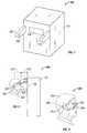
- the wavefront measurement systemis shown and generally designated 100 .
- FIG. 1shows that the wavefront measurement system 100 includes a main housing 101 in which a slot 102 allows for one or two cameras (not shown) to be placed in order to image the front of a patient (not shown), while allowing the patient to look at a virtual or real fixation target. Additionally, there may be a right housing 104 and a left housing 106 , each extending from the main housing 101 and each having an opening 108 for a camera (not shown).
- FIG. 2shows a patient 202 facing the wavefront measuring system main housing 101 and slot 102 .
- a camera(not shown) mounted within right housing 104 photographs the side of patient's 202 head, including the patient's 202 ear 204 and nose 206 .
- the camera or cameras mounted in slot 102image the patient's 202 eyes 208 , and specifically the pupil 210 .
- FIG. 3shows a patient 302 wearing a eyeglasses frame 304 with known dimensions.
- the frame 304is mounted to a nose molding 306 , and an ear molding 308 .
- registration markers 310 and 312may be placed upon the nose molding 306 and ear molding 308 respectively.
- the patient 302may then be imaged by the wavefront measuring system 100 while wearing the frame 304 such that the wavefront measuring system 100 may use either the test frame 304 , the registration markers 310 and 312 , or both in order to more accurately quantify the patient's 302 head and face for future eyeglass fittings.
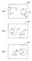
- FIG. 4shows a right image of a patient and is generally designated 400 .
- the patient's right corneal apex 406 and right ear molding 408can also be seen in the image.
- the registration marks 410 on the right nose molding 404 and the registration marks 412 on the right ear molding 408aid the computer in determining the exact locations of the right nose molding 404 and the right ear molding 408 with respect to each other, and with respect to the patient's right corneal apex 406 .
- FIG. 5shows a right front image of a patient and is generally designated 420 .
- the patient's right pupil 426 , the right lens opening 402 , the right nose molding 404 , and the registration marks 410can be seen in the image.
- FIG. 6shows a left front image of a patient and is generally designated 430 .
- the patient's left pupil 427 , the left lens opening 403 , the left nose molding 405 , and the registration marks 411can be seen in the image.
- FIG. 7shows a left side image of a patient and is generally designated 440 .
- a left lens opening 403attached to a left nose molding 405 .
- the patient's left pupil 427 and left ear molding 409can also be seen in the image.
- the registration marks 411 on the left nose molding 405 and the registration marks 413 on the left ear molding 409aid the computer in determining the exact locations of the left nose molding 405 and the left ear molding 409 with respect to each other, and with respect to the patient's left pupil 427 .
- the computerAfter imaging the patient, the computer would have stored a right and a left side view, and two frontal views of the patient wearing the test frame 304 , including the moldable nose pads 306 and moldable ear pads 308 , while being examined with the wavefront measuring system. From the images, the exact location of the moldable nose pads 306 and the moldable ear pads 308 with respect to each other and with respect to the patient's pupils 426 and 427 , corneal apexes 406 and 407 , and the test frame 304 can be determined.
- FIG. 8shows a frontal image of a patient's face and is generally designated 450 .
- the imagecontains both lens openings 402 , 403 , nose moldings 404 , 405 , and pupils 426 and 427 .
- FIG. 9is a flowchart illustrating a sequence of steps to manufacture custom eyeglasses and is generally designated 500 .
- step 502the patient looks into the wavefront measuring device in order to be imaged by the device.
- step 504mandates that a plurality of cameras image the front and sides of the patient's face as can be seen in FIG. 2 .
- Camera placementis only constrained by the need to image both the sides and front face of the patient, and therefore is not constricted to the configuration as depicted in FIG. 2 .
- Step 506indicates that it is necessary to take images at various gazing angles of the patient's eyes. Optical alignment for all gazing angles is a critical requirement when correcting for higher order aberrations.
- step 506should be performed to ensure the custom eyeglasses function properly. Additionally, step 507 requires that wavefront measurements be taken for each of the images taken in step 506 .
- the computerprocesses the information and returns the output in step 510 .
- the outputconsists of the locations of the patient's pupils, center of the pupils, pupil distance, width of face, ear location, distance of the corneal apex from the wavefront measuring device, distance from the ear to corneal apex, and other parameters necessary to measure a patient's head and face for eyeglass fittings.
- lens-mounting parametersa pair of custom spectacles may be produced as indicated by step 512 .
- FIG. 10is a flowchart illustrating an alternative sequence of steps to manufacture custom eyeglasses and is generally designated 600 .
- step 602moldable material is applied around the nose and the area around the ears of the patient as can be seen in FIG. 3 .
- the moldable materialallows for a more conventional means of obtaining an accurate surface profile of the patient's nose and around the ears.
- step 604calls for registration markers are added before the moldings cure.
- the registration markersprovide a means for the wavefront measuring device to gauge the molds with respect to the patient's face.
- Step 606attaches a test frame of known dimensions to the moldable material before it cures.
- step 604may or may not be affixed to the frame in step 606 .
- the frame of step 606 and the molding of step 602 along with the registration markers of 604can all be seen in FIG. 3 .
- Step 608similarly to step 502 of FIG. 9 , calls for the patient to look into the wavefront measuring device.
- the computerstores a right and a left side view, and one or two frontal views of the patient wearing the test frame including the moldable pads.
- the computer in step 612returns the output of all the same parameters as indicated by step 510 of FIG. 9 , but additionally includes the information with respect to the test frame and the moldings.
- step 614calls for the moldings to be duplicated or transformed into custom eyeglass hinges and nose pads for conventional frames.
- the various moldingsmay be made of silicone.
- any material capable of conforming to a person's headis suitable for use in the system.
- System 700includes a main housing 702 having a right side housing 704 and a left side housing (not shown in this Figure) spaced apart to receive a person's head 706 such that his or her ears 708 are positioned between the side housings, and the patient's eyes 710 is positioned adjacent slot 711 on main housing 702 .
- the patientviews a real fixation target 712 along an optical axis 714 .
- a tiltable dichroic beam splitter 716Positioned along the optical axis 714 is a tiltable dichroic beam splitter 716 which splits a portion of the light passing from the patient's eye 710 to a secondary axis 718 .
- the light passing along the secondary axispasses through a pair of imaging lenses 720 and 722 and onto a wavefront sensor 724 , such as a Hartmann-Shack sensor.
- an additional beam splitter 726may be positioned along the optical axis to split a portion of light passing along the optical axis to a tertiary axis 730 .
- the light passing along the tertiary axispasses through an imaging lens 732 and onto an imaging device, such as a charge coupled device (CCD) camera.
- CCDcharge coupled device
- a second, virtual target 742may be provided along a second optical axis 740 .
- beam splitter 716may be pivoted in angles 744 , and may also be moved in directions 746 to properly position the splitter 716 on second optical axis 740 (as shown by dashed lines 748 ).
- Using the eyeglass measuring system 700facilitates the manufacturing of eyeglasses in accordance with method 600 .
- a corrective lensmay be created which precisely matches the patients needs.
- FIG. 12is a functional block diagram of an automated eyeglass frame fitting system 1200 .
- the system 1200accurately determines the pupilary distance (PD) and SEG height associated with a particular patient and a particular eyeglass frame. Such measurements can then be used, for example, to accurately position the corrective lenses within the eyeglass frame.
- PDpupilary distance
- SEG heightassociated with a particular patient and a particular eyeglass frame.
- the system 1200can be configured to capture one or more images of a patient wearing the desired eyeglass frames that are to be fitted with the corrective lenses.
- the captured imagesare processed to determine information to permit positioning lenses in the frame, for example, the pupilary distance and SEG height associated with the frames and the patient.
- the system 1200includes a patient positioner 1202 that is configured to approximately locate the position of the patient's head within a predetermined field of view.
- the positioner 1202can be, for example, a chin rest, forehead rest, ear locator, nose bridge, and the like, or some other positioner or combination of positioners.
- the positioner 1202need not be solely a mechanical positioner, but can also include an audio, optical, or some other type of electrical positioner.
- An imager 1210can be configured to capture one or more images of the patient's head, showing the relationship of the eyeglass frame to a portion of the patient's head.
- An illuminator 1220can be configured to illuminate the patient's head, and can be configured to provide or create fiducial marks on the captured images.
- An image processor 1230 coupled to the imager 1210analyzes the captured images. The image processor 1230 examines the captured images and is configured to determine the pupilary distance, SEG height, and pantoscopic tilt of the eyeglass frames, where the pantoscopic tilt refers to the angle of the frame from vertical. The distance of the lenses from the respective corneas, typically referred to as vertex distance, can also be determined.
- the captured images as well as the resultant measurementscan be output on a display 1260 or some other output device such as, for example, a printer or magnetic strip card writer.
- a processor 1240 in communication with memory 1250can control some or all of the functions associated with the patient positioner 1202 , imager 1210 , illuminator 1220 , image processor 1230 , and display 1260 . Additionally, some or all of the functions performed by the various functional blocks within the system 1200 can be stored as one or more processor readable instructions stored in memory 1250 and executed by the processor 1240 .
- the image processing functioncan be stored as software in memory 1250 and performed by the processor 1240 executing the image processing software.
- the imager 1210can include one or more cameras or some other imaging apparatus.
- a cameracan be a color camera or a monochrome camera. Additionally, one or more cameras can be configured with telecentric lenses.
- the imager 1210can include one or more cameras, CMOS cameras, charge coupled devices, photosensitive devices, and the like, or some other image capturing device.
- the illuminator 1220can include one or more light sources and can include one or more light filters.
- one or more of the light sourcescan include incandescent light sources, fluorescent light sources, halogen light sources, xenon light sources, LED light sources, gas discharge light sources, radiant light sources, laser light sources, and the like, or some other light source.
- the illuminator 1220can include white light sources, colored light sources, visible light sources, non-visible light sources, or a combination of light sources. Filters can include optical filters, gradient filters, polarizing filters, and the like, or some other type of filter. In one embodiment, the processor 1240 controls the duration and intensity of light from the illuminator 1220 . In another embodiment, one or more illuminators can include one or more light sources. Light from some of the light sources may be filtered using optical filters to color the light emitted from the light source. The image processor may then be configured to identify features based in part on color detection.
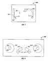
- FIG. 13Ais an embodiment of the frame fitting system described in FIG. 12 .
- FIG. 13Ashows the relationship of the frame fitting system to a patient 1308 wearing spectacle frames 1306 .
- the patient 1308can be positioned relative to image capture equipment using a forehead support 1304 .
- the imager within the systemutilizes two cameras 1310 and 1312 to capture images of the patient or subject 1308 wearing spectacle frames 1306 .
- the cameras 1310 and 1312can be, for example, CMOS cameras.
- a first camera 1310is positioned to capture an image in front of the subject 1308 in the horizontal plane of the subject's eyes with the axis between the eyes.
- the first camera 1310advantageously images the patient 1308 through a beam splitter 1330 placed at substantially 45 degrees.
- the beam splitter 1330allows the patient 1308 to see and focus on an object in the distance without the camera 1310 being visible.
- the use of the beam splitter 1330advantageously allows the subject to look outside of the apparatus and focus on one or more real or fixation targets placed at one or more distances and/or locations within a field of view.
- the use of real or fixation targets at various locations and distancesallows the system to capture and measure pupil locations for various eye placements.
- a first pupil readingcan be determined using a first set of images captured while the subject is focused on a target placed at a typical reading distance and a typical reading angle.
- a second pupil readingcan be determined using a second set of images captured while the subject is focused on a distant object.
- the beam splitter 1330may alternatively be a partially silvered mirror, dichroic filter, or some other light splitting device.
- the systemallows the subject 1308 to focus on a distant object without the image being occluded by the first camera 1310 . This ensures the position of the subject's eyes is not affected by objects in a near field of view. Such near field objects may, for example, affect the accuracy of the pupilary distance determination.
- a second camera 1312can be positioned to capture an image that is substantially perpendicular to the image captured by the first camera 1310 .
- the second camera 1312can be configured to capture an image of the side of the patient 1308 .
- the second camera 1312can be positioned with the axis of the camera approximately in line with the subject's cornea.
- An optional third cameracan be positioned above, facing down in line with a vertical axis coincident with a point between the patient's eyes.
- Each of the cameras 1310 and 1312can be configured to simultaneously capture images of the patient 1308 .
- the cameras 1310 and 1312can be configured to sequentially capture images of the patient 1308 . If the cameras, for example 1310 and 1312 , are configured to sequentially capture images, the time between successive images may be controlled to minimize potential movement of the patient 1308 between images. In one embodiment using sequential image capture, the cameras may be cycled to capture images at a rate of approximately 15 frames per second.
- a single cameracan capture multiple images. For example, the position of a single camera may be moved prior to capturing each of the desired images.
- filters and reflectors and/or different wavelength illumination sourcescan be used to allow a single camera to simultaneously capture multiple views.
- a single camera having a wide field of viewmay simultaneously capture both the front and side view of the patient 1308 using two wavelength dependent beam splitters and two different wavelengths for illumination.
- An alternative single camera embodimentis shown in FIG. 13B .
- Image analysiscan be performed in an image processor (not shown) to determine the position and angle of the frames in relation to the subject 1308 .
- a calibration routinecan orient the position and image scaling of the multiple cameras such that an object imaged by the camera, for example 1310 , can be located and measured in three dimensions in software.
- the calibration routinecan include, for example, placing an object, such as a calibration object or calibration fixture, in the field of view of the cameras, for example 1310 and 1312 , and capturing images of the object.
- the image processoris then calibrated using the captured images of the calibration fixture.
- the calibration objectcan be imaged to allow each camera used in the system to be calibrated with respect to the other camera(s).
- the calibration procedurecan be performed with a three-dimensional spatial calibration fixture. Calibration of the cameras enables the image processor to determine spatial relations between items identified in each view.
- the fixturecan have, for example, a surface that is marked with a grid of known dimensions.
- the images captured by the camerascan then be calibrated to the dimensions of the grid.
- the calibration fixtureis a block having a surface covered in a grid of known dimensions. The block is placed with a face of the block at approximately 45 degrees relative to the axis of the first and second cameras, 1310 and 1312 .
- the calibration objectis a flat sheet having a grid of known dimensions. The sheet is placed at approximately 45 degrees relative to the axis of the first and second cameras 1310 and 1312 .
- the calibration objectis a scale having markings of known dimensions. The scale is placed at approximately 45 degrees relative to the axis of the first and second cameras 1310 and 1312 .
- the images of the patient 1308 captured from each cameracan be analyzed by image recognition software that locates the subject's pupil and the outline of the frame 1306 in each captured image.
- the image processordetermines the location of the frame 1306 to the eye and gives coordinates for pupil distance, SEG height from the front view, and vertex distance and pantoscopic tilt from the side.
- the overhead view camera(not shown) can be utilized to verify that the patient 1308 is aligned with the first and second cameras 1310 and 1312 . If the image processor determines that the patient 1308 is not aligned with the cameras, the image processor can provide additional information, based in part on the overhead image, to correct the measurements for angular displacement between the camera and the optical axis of the eye.
- the systemcan use controlled lighting to simplify the image processing function.
- the purpose of the controlled lightingis twofold. Indirect, even, lighting can illuminate the frames 1306 and face to improve the success of the image analysis routine.
- directional point source lights, or fiducial markerscan be added in predetermined locations.
- the point light sourcescan be configured to reflect off the cornea in a specific pattern.
- the image processor or image processing softwarecan search each captured image for the specific pattern.
- the predetermined patternmay be two or more points outside the pupil in the front view and one light source reflection captured in the side image.
- the point source lightingcan be of a specific color, making them easier to identify in an image via a spectral signature.
- filtersmay be placed in front of one or more light sources to alter the color or spectrum of the light emitted from the light source.
- the lightscan be computer controlled such as by the processor 1240 of FIG. 12 , allowing them to be turned on and off between frames. Cycling the lights allows one image to be taken with the lights on. One or more lights can then be turned off before the next image so as not to be included in the image used to detect the pupil.
- the successive imagescan be captured in a narrow time frame such that the movement between the images would be small or essentially zero.
- the two imagescan be overlaid or compared to orient index marks from light source reflections to the pupil.
- a first light source 1342is placed along one side of the patient's 1308 face.
- a second light source 1344is placed along an opposite side of the patient's 1308 face.
- Each of the light sourcescan be, for example, an array of LED lights or an incandescent lamp.
- the corneareflects the light from the light sources, 1342 and 1344 .
- the spherical shape of the corneaproduces a reflection of the light sources on the surface of the cornea that is substantially localized, even from a substantially uniform light source.
- each of the light sources, for example 1342 and 1344produces a reflection on each of the patient's 1308 cornea.
- Each of the reflectionsis substantially localized as a point on the cornea.
- the image processorcan search the captured images for the point of reflections on the cornea. For example, the image processor can search the images for the points that have high light intensity. Once these points on the cornea are located in the images, the image processor searches for the dark circle of the pupil within a specified area of the reflection.
- the image processorcan use, for example, connectivity or blob analysis to distinguish the pupil.
- the image processorperforms a two dimensional search of the images for the pupil. The image processor then determines the center of the pupil.
- the subject 1308can be imaged first without the spectacle frame 1306 , than again with the spectacle frame 1306 in place. Both sets of images can be overlaid using features or landmarks common to both images.
- the image processorcan take the difference of the two images allowing the frames 1306 to be extracted from the images. This technique is especially useful when the spectacles 1306 have stylized features, or are of a design which prevents the fiducial marks from being imaged.
- the image processordetermines the left and right spectacle frame box.
- the spectacle frame boxis used, for example, in determining the SEG height.
- the spectacle frame determinationcan be performed automatically by means of filters and edge detection algorithms.
- the spectacle frame determinationcan be performed by allowing an operator to provide input to the system through a user interface, which allows the operator to drag or draw a box around the image of the spectacle frames until the edges of the box are approximately tangent with an edge of each of the four sides of the lens frame.
- the systemmay allow an operator to view a captured image of the patient 1308 and allow the operator to use a mouse or other input device to draw a box around each of the lens frames.
- FIG. 13Bis a functional block diagram of an alternative frame fitter 1300 embodiment that uses a single camera 1310 .
- the functional block diagramshows an overhead view of a patient or subject 1308 positioned in relation to a single camera frame fitter system 1300 .
- a camera 1310is configured to image a patient 1308 through the use of multiple dichroic beam splitters 1352 and 1354 and a broadband beam splitter 1330 used to allow the patient 1308 to focus on an image in the distance without having the camera 1310 in the field of view.
- the camera 1310is positioned with an image axis that is substantially parallel to the image axis of the patient 1308 .
- the camera 1310can capture a side image of the patient 1308 using a first dichroic beam splitter 1352 placed in the filed of view of the camera 1310 .
- the first dichroic beam splitter 1352can be, for example, placed at substantially a 45 degree angle relative to the camera image axis.
- the first dichroic beam splitter 1352can also be positioned approximately along an axis extending through the side of the patient's head, substantially perpendicular to the patient's image axis.
- a second dichroic beam splitter 1354is placed at approximately 45 degrees relative to the image axis of the camera 1310 and is placed behind the first dichroic beam splitter 1352 .
- the front image of the patient 1308reflects off of the broadband beam splitter 1330 placed in front of the patient 1308 .
- the front image from the broadband beam splitter 1330reflects to the second dichroic beam splitter 1354 , passes through the first dichroic beam splitter 1352 and is captured by the camera 1310 .
- a first light source 1348is a colored light source, where colored light refers to a spectrum of light that is narrower than a white light source.
- the first light source 1348can be, for example a red light source, or a light source emitting substantially red light, that illuminates the patient 1308 with a spectrum of light that is substantially within the red spectrum.
- the first dichroic beam splitter 1352can filter and reflect a light spectrum that corresponds to the spectrum of the light source 1348 and passes light that is above or below a predetermined wavelength.
- the first dichroic beam splitter 1352is configured to be a red dichroic beam splitter that reflects red light and passes green light.
- the camera 1310therefore only receives an image representing the wavelength of the light source in combination with the dichroic beam splitters, 1352 and 1354 .
- the second light source 1346can be a colored light source, such as a green light source, or a light source that emits substantially green light.
- the second dichroic beam splitter 1354can be a green dichroic beam splitter that is configured to reflect only green light corresponding to the spectrum of the light source 1346 .
- the second dichroic beam splitter 1354is configured to pass all other wavelengths.
- the light sources 1346 and 1348need not be green and red light sources, but may be any type of colored light sources, or may be narrowband light sources that can emit radiation in a visible spectrum, non-visible spectrum, or combination of visible and non-visible spectrums.
- the camera 1310captures an image that is a composite of a side image reflected by the red dichroic beam splitter 1352 and a front image reflected by the green dichroic beam splitter 1354 .
- the image processor(not shown) can be configured to process the images based in part on the spectrum of the captured image. Thus, by analyzing the red portions of the image, the image processor can isolate portions of the side image. Similarly, by analyzing the green images, the image processor (not shown) can analyze the front image. Alternatively, the front and side images may be captured sequentially and analyzed as separate images.
- the camera 1310can capture two images in succession, the first with only the red light source 1348 illuminated, reflecting off of the red dichroic beam splitter 1352 , representing the side image to the camera 1310 .
- the second imagecan be generated using the green light illumination 1346 , and presenting a front image reflecting off the green dichroic beam splitter 1354 to the camera 1310 .
- the successive image capture approachcan thus be used with color cameras as well as monochrome cameras.
- FIGS. 14 through 16show captured images and the process of analyzing the images for the desired information. Although screen shots of captured images are shown in the figures, the images need not be displayed to an operator, and the system may perform the image analysis without displaying the captured images.
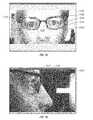
- FIG. 14shows a screen shot of side 1402 and front 1404 view images of a subject captured using the frame fitting system of FIG. 13 .
- the imagesinclude fiducial marks that were added by the image processor during determination of the pupil. Additionally, the images include highlighting to indicate the area determined to be the pupils. The fiducial marks and highlighting were added by the image processing system and are not part of the original captured images.
- the front image 1404shows fiducial marks added by the image processor and the areas identified as the pupils.
- the image processordetermines the position of a first fiducial mark 1412 in the subject's right eye by analyzing the image for a reflection from a first light source.
- the image processorcan, for example, search the image for peaks in intensity corresponding to reflections of the light sources off of the subject's cornea.
- the image processorcan determine the position of a second fiducial mark 1414 corresponding to a reflection of a second light source off of the subject's cornea.
- the image processorcan use the fiducial marks to determine the pupil 1420 of the right eye.
- the image processorcan use the fiducial marks as indices to begin a connectivity or blob analysis in search for the dark pupil 1420 area.
- the right pupil 1420is shown as a highlighted area in the subject's right eye.
- the image processorcan determine the positions of fiducial marks in the subject's left eye.
- the image processordetermines a first fiducial mark 1432 corresponding to a reflection of a first light source off of the left cornea.
- the image processoralso determines the position of a second fiducial mark 1434 corresponding to a reflection of a second light source off of the left cornea.
- the two fiducial marks 4132 and 1434are used by the image processor in determining the left pupil 1440 .
- the left pupil 1440is shown as a highlighted area in the subject's left eye.
- the image processorperforms a similar analysis on the side view 1402 .
- the image processordetermines the position of fiducial marks 1452 and 1454 that correspond to the reflections of the light sources off of the cornea.
- the image processorcan use the fiducial marks 1452 and 1454 to determine the pupil and to determine the edge of the cornea 1456 .
- FIG. 15is a screen shot of a captured front image with an outline of a frame determined by a frame locator.
- the frame locatorcan be, for example, part of the image processor of FIG. 12 .
- the front view image 1510includes a view of the subject wearing desired frames 1510 .
- the position of the frameis located as part of the determination of the position of the corrective lens within the frame.
- the image processordetermines the position of the left and right lens frames.
- the image processorcan determine the position of the frames, for example, by using edge detection filters such as Sobel or Roberts type in conjunction with connectivity or blob analysis.
- the image processorcan determine a high level of contrast, for example, in the portion of the image near the bridge of the subject's nose.
- the image processorcan then use edge detection filters and connectivity or blob analysis to determine the remainder of the frame.
- the image processorcan determine the position of a box 1530 that outlines each lens frame.
- the image processordetermines the box 1530 having sides, 1532 , 1534 , 1536 , and 1538 , tangent to each of the lens frame sides.
- the image processorcan use, for example, edge detection based in part on the blob analysis of the frame.
- the image processorcan determine the position of the lens frame for the left eye corrective lens.
- the image processordetermines the left edge 1536 of the box 1530 by determining the inside edge of the centermost portion of the lens frame.
- the image processorsimilarly can determine the top edge 1532 , bottom edge 1534 , and right edge 1538 of the box 1530 .
- the image processorthen repeats the process for the right eye corrective lens frame.
- two front images of the subjectare captured.
- a first imageis captured of the subject without spectacle frames.
- a second imageis captured of the subject wearing the desired spectacle frames.
- the image processoraligns the two captured images, for example using correlation analysis.
- the image processorcan then extract the image of the spectacle frame by taking the difference of the two images.
- the image processorcan then determine the position of the lens frames using the process described above.
- the captured front image 1502is displayed to an operator.
- the position of the lens framesare identified using input from an operator.
- the frame fitting systemreceives an input from the operator identifying the position of the lens frames.
- the operatoruses a computer mouse to drag a box 1530 having sides that are tangent to the lens frames. The operator repeats the entry for the right and left lens frames.
- FIG. 16is a screen shot of a side view image 1602 showing a subject wearing desired spectacle frames.
- the image processorautomatically determines the pantoscopic tilt of the frame. As before, the image processor can automatically determine the pantoscopic tilt by analyzing one or more captured images.
- the image processoruses edge detection filters and connectivity or blob analysis to identify the spectacle frames within the image.
- the image processordetermines the pantoscopic tilt of the frame by determining a line tangent to a front of the frame and measuring the angle from vertical.
- two side images of the subjectare captured, one without spectacle frames and one with spectacle frames.
- the two imagesare aligned and the difference of the images is determined in order to identify the spectacle frame.
- the image processoruses edge detection and blob analysis to identify the outline of the frame and to determine the tangent line defining the pantoscopic tilt.
- the frame fitting systemdisplays the side image 1602 to an operator.
- the operatoruses an input device, such as a computer mouse, to draw or align a tangent to the frame.
- the linedefines the pantoscopic tilt.
- the frame fitting systemreceives the data corresponding to the line to determine the pantoscopic tilt.
- FIG. 17is a flowchart of a frame fitting process 1700 that can be performed by the frame fitting system of FIG. 12 .
- the process 1700begins by capturing the front and side images of a subject wearing desired spectacle frames.
- one or more camerascan be controlled by a processor or controller to capture the front and side images of the subject.
- the processorcan also control one or more light sources in an illuminator during the image capture.
- the process 1700proceeds to block 1710 where the frame, and particularly the position of the right and left lens frames, is located.
- the frame locatoris integrated in the image processor. The frame locator determines the right and left lens frames and also determines the pantoscopic tilt of the frame.
- the image processorproceeds to block 1720 to locate the pupils in the images.
- the image processornext proceeds to block 1730 where the frame fitting information, such as pupilary distance and SEG height are determined. The information can be reported or otherwise displayed to an operator.
- the image capture, image processing, and parameter determinationare performed local to the subject, such as in a stand alone unit.
- the image captureis performed local to the subject and the image processing, parameter determination, and reporting are performed remote from the subject.
- the image capturecan be performed in an optometrists office and the image processing performed at a remote site where the lenses are produced and assembled in the eyeglasses.
- FIG. 18is a detailed flowchart of the pupil location process 1720 performed by the image processor.
- the process 1720begins at block 1802 where the image processor compares the captured image against one or more predetermined thresholds.
- the image processorcompares the red, green, and blue pixels against one or more predetermined thresholds to determine the presence of bright pixels. Those pixels that exceed the threshold are determined to be bright pixels.
- the image processorthen proceeds to block 1810 where connectivity or blob analysis is performed on the captured image to determine the bright spots.
- the image processorcan perform connectivity analysis on each of the pixels that exceeds the predetermined thresholds.
- the image processorproduces one or more blobs based on the connectivity analysis.
- the image processornext proceeds to block 1820 where the identified blobs are filtered based on size and shape characteristics. Because the position of the one or more light sources is known, the approximate shape and location of the corneal reflections is known. Those shapes and positions of blobs which do not fall within the filter criteria are rejected as not corresponding to light reflections from the subject's cornea.
- the image processornext proceeds to block 1830 where the image processor performs a threshold for dark pixels. Again, where the captured image is in color, the image processor compares the captured red, green, and blue pixels against one or more predetermined dark thresholds.
- the image processornext proceeds to block 1840 where connectivity or blob analysis is performed on the identified dark pixels.
- Each of the dark pixelscan define a dark blob.
- One or more of the dark pixelsmay belong to the same dark blob.
- the image processorproceeds to block 1850 to filter the dark blobs with respect to, for example, size and shape characteristics.
- the image processoridentifies the pupils as approximately dark circles that occur within predefined regions of the image. Those dark blobs that do not correspond to such criteria can be filtered out.
- the image processorproceeds to block 1860 to determine the location of the pupils based on the bright blob analysis and the dark blob analysis.
- the bright spotscorrespond to reflection of the light sources.
- the dark spotsmay correspond to the pupils.
- the spherical shape of the cornea and the placement of the light sources relative to the subjectresult in the bright light reflections being positioned near the pupil regions.
- the image processorcan use the bright light reflections as fiducial marks used to help identify the pupils.
- the image processorcan use the two dimensional shape analysis along with fiducial marks to determine the position of the pupils.
- FIGS. 17 and 18show the operation of steps in a particular order. However, one may appreciate that the order of such steps is not necessarily limited to the order shown in the flowcharts. For example, the frame location step 1710 and the pupil location step 1720 do not need to be performed in the order shown, but may be performed in the opposite order. Additionally, the bright and dark blob analysis can be performed in an order other than what is shown in FIG. 18 . Other modifications, including reordering, additions, and omissions may be made to the flowcharts of FIGS. 17 and 18 .
- a frame fitting system and method for fitting spectacle framesis disclosed.
- the systemcaptures at least one front and side image of a subject wearing desired spectacle frames.
- the systemuses an image processor using a two dimensional image processing algorithm to identify the position of the subject's pupils. Additionally, the image processor uses two dimensional image processing techniques to identify lens frames and a pantoscopic tilt of the frame.
- the systemcan determine the pupilary distance and SEG height of lenses within a particular spectacle frame to ensure proper fitting of the lenses within the frames.
Landscapes
- Physics & Mathematics (AREA)
- Health & Medical Sciences (AREA)
- General Physics & Mathematics (AREA)
- Ophthalmology & Optometry (AREA)
- Optics & Photonics (AREA)
- Geometry (AREA)
- Eyeglasses (AREA)
- Eye Examination Apparatus (AREA)
- Testing Of Optical Devices Or Fibers (AREA)
- Image Processing (AREA)
Abstract
Description
Claims (18)
Priority Applications (1)
| Application Number | Priority Date | Filing Date | Title |
|---|---|---|---|
| US12/208,295US7845797B2 (en) | 2001-10-25 | 2008-09-10 | Custom eyeglass manufacturing method |
Applications Claiming Priority (3)
| Application Number | Priority Date | Filing Date | Title |
|---|---|---|---|
| US10/046,656US6682195B2 (en) | 2001-10-25 | 2001-10-25 | Custom eyeglass manufacturing method |
| US10/756,243US7434931B2 (en) | 2001-10-25 | 2004-01-13 | Custom eyeglass manufacturing method |
| US12/208,295US7845797B2 (en) | 2001-10-25 | 2008-09-10 | Custom eyeglass manufacturing method |
Related Parent Applications (1)
| Application Number | Title | Priority Date | Filing Date |
|---|---|---|---|
| US10/756,243ContinuationUS7434931B2 (en) | 2001-10-25 | 2004-01-13 | Custom eyeglass manufacturing method |
Publications (2)
| Publication Number | Publication Date |
|---|---|
| US20090051871A1 US20090051871A1 (en) | 2009-02-26 |
| US7845797B2true US7845797B2 (en) | 2010-12-07 |
Family
ID=21944656
Family Applications (2)
| Application Number | Title | Priority Date | Filing Date |
|---|---|---|---|
| US10/046,656Expired - LifetimeUS6682195B2 (en) | 2001-10-25 | 2001-10-25 | Custom eyeglass manufacturing method |
| US12/208,295Expired - Fee RelatedUS7845797B2 (en) | 2001-10-25 | 2008-09-10 | Custom eyeglass manufacturing method |
Family Applications Before (1)
| Application Number | Title | Priority Date | Filing Date |
|---|---|---|---|
| US10/046,656Expired - LifetimeUS6682195B2 (en) | 2001-10-25 | 2001-10-25 | Custom eyeglass manufacturing method |
Country Status (5)
| Country | Link |
|---|---|
| US (2) | US6682195B2 (en) |
| EP (1) | EP1446694B1 (en) |
| JP (1) | JP4361806B2 (en) |
| AU (1) | AU2002367536B2 (en) |
| WO (1) | WO2003079097A1 (en) |
Cited By (14)
| Publication number | Priority date | Publication date | Assignee | Title |
|---|---|---|---|---|
| US20100198381A1 (en)* | 2007-01-30 | 2010-08-05 | Zvi Feldman | Systems and methods for producing clip-ons for a primary eyewear |
| US20130042489A1 (en)* | 2011-08-16 | 2013-02-21 | Oded Katzman | Device and method for measuring pantoscopic tilt |
| US20150049952A1 (en)* | 2013-08-14 | 2015-02-19 | Vsp Labs, Inc. | Systems and methods of measuring facial characteristics |
| WO2015027196A1 (en) | 2013-08-22 | 2015-02-26 | Bespoke, Inc. | Method and system to create custom products |
| US20150243015A1 (en)* | 2012-09-07 | 2015-08-27 | Tipheret | Method and device for preparing a spectacle frame |
| US9208608B2 (en) | 2012-05-23 | 2015-12-08 | Glasses.Com, Inc. | Systems and methods for feature tracking |
| US9236024B2 (en) | 2011-12-06 | 2016-01-12 | Glasses.Com Inc. | Systems and methods for obtaining a pupillary distance measurement using a mobile computing device |
| US9286715B2 (en) | 2012-05-23 | 2016-03-15 | Glasses.Com Inc. | Systems and methods for adjusting a virtual try-on |
| US9429773B2 (en) | 2013-03-12 | 2016-08-30 | Adi Ben-Shahar | Method and apparatus for design and fabrication of customized eyewear |
| US9483853B2 (en) | 2012-05-23 | 2016-11-01 | Glasses.Com Inc. | Systems and methods to display rendered images |
| US9804410B2 (en) | 2013-03-12 | 2017-10-31 | Adi Ben-Shahar | Method and apparatus for design and fabrication of customized eyewear |
| EP3270099A4 (en)* | 2015-03-10 | 2018-08-22 | Hoya Lens Thailand Ltd. | Measurement device for eyeglasses-wearing parameter, measurement program for eyeglasses-wearing parameter, and position designation method |
| US10685457B2 (en) | 2018-11-15 | 2020-06-16 | Vision Service Plan | Systems and methods for visualizing eyewear on a user |
| US11238611B2 (en)* | 2019-07-09 | 2022-02-01 | Electric Avenue Software, Inc. | System and method for eyewear sizing |
Families Citing this family (113)
| Publication number | Priority date | Publication date | Assignee | Title |
|---|---|---|---|---|
| US20030128336A1 (en)* | 2001-12-28 | 2003-07-10 | Jethmalani Jagdish M. | Customized lenses |
| US6986579B2 (en) | 1999-07-02 | 2006-01-17 | E-Vision, Llc | Method of manufacturing an electro-active lens |
| US6871951B2 (en)* | 2000-06-23 | 2005-03-29 | E-Vision, Llc | Electro-optic lens with integrated components |
| US6619799B1 (en) | 1999-07-02 | 2003-09-16 | E-Vision, Llc | Optical lens system with electro-active lens having alterably different focal lengths |
| US7023594B2 (en)* | 2000-06-23 | 2006-04-04 | E-Vision, Llc | Electro-optic lens with integrated components |
| US6857741B2 (en)* | 2002-01-16 | 2005-02-22 | E-Vision, Llc | Electro-active multi-focal spectacle lens |
| US7988286B2 (en) | 1999-07-02 | 2011-08-02 | E-Vision Llc | Static progressive surface region in optical communication with a dynamic optic |
| US7404636B2 (en) | 1999-07-02 | 2008-07-29 | E-Vision, Llc | Electro-active spectacle employing modal liquid crystal lenses |
| US20070258039A1 (en)* | 1999-07-02 | 2007-11-08 | Duston Dwight P | Spectacle frame bridge housing electronics for electro-active spectacle lenses |
| US7264354B2 (en)* | 1999-07-02 | 2007-09-04 | E-Vision, Llc | Method and apparatus for correcting vision using an electro-active phoropter |
| US7775660B2 (en)* | 1999-07-02 | 2010-08-17 | E-Vision Llc | Electro-active ophthalmic lens having an optical power blending region |
| US7290875B2 (en) | 2004-11-02 | 2007-11-06 | Blum Ronald D | Electro-active spectacles and method of fabricating same |
| US20090103044A1 (en)* | 1999-07-02 | 2009-04-23 | Duston Dwight P | Spectacle frame bridge housing electronics for electro-active spectacle lenses |
| US7290876B2 (en)* | 1999-07-02 | 2007-11-06 | E-Vision, Llc | Method and system for electro-active spectacle lens design |
| US7604349B2 (en)* | 1999-07-02 | 2009-10-20 | E-Vision, Llc | Static progressive surface region in optical communication with a dynamic optic |
| BR0213012A (en)* | 2001-10-05 | 2004-12-28 | E Vision Llc | Hybrid Electroactive Lenses |
| US7434931B2 (en)* | 2001-10-25 | 2008-10-14 | Ophthonix | Custom eyeglass manufacturing method |
| US6682195B2 (en)* | 2001-10-25 | 2004-01-27 | Ophthonix, Inc. | Custom eyeglass manufacturing method |
| US20080106633A1 (en)* | 2002-03-13 | 2008-05-08 | Blum Ronald D | Electro-optic lens with integrated components for varying refractive properties |
| US7941333B2 (en)* | 2003-06-30 | 2011-05-10 | Embarq Holdings Company, LLP | Method and system for identifying and categorizing past due telecommunication service orders |
| US8059803B1 (en)* | 2003-06-30 | 2011-11-15 | Embarq Holdings Company, Llc | System and method for ordered processing of telecommunicaion service orders |
| US7195353B2 (en)* | 2003-08-15 | 2007-03-27 | E-Vision, Llc | Enhanced electro-active lens system |
| US7188950B2 (en)* | 2003-11-14 | 2007-03-13 | Ophthonix, Inc. | Eyeglass dispensing method |
| EP1700153A1 (en)* | 2003-11-14 | 2006-09-13 | Ophthonix, Inc. | Eyeglass manufacturing method |
| US7234810B2 (en)* | 2003-11-14 | 2007-06-26 | Ophthonix, Inc. | System for manufacturing an optical lens |
| US7154529B2 (en)* | 2004-03-12 | 2006-12-26 | Hoke Donald G | System and method for enabling a person to view images of the person wearing an accessory before purchasing the accessory |
| US20050237485A1 (en)* | 2004-04-21 | 2005-10-27 | Blum Ronald D | Method and apparatus for correcting vision |
| US8931896B2 (en) | 2004-11-02 | 2015-01-13 | E-Vision Smart Optics Inc. | Eyewear including a docking station |
| US9801709B2 (en) | 2004-11-02 | 2017-10-31 | E-Vision Smart Optics, Inc. | Electro-active intraocular lenses |
| JP5064229B2 (en)* | 2004-11-02 | 2012-10-31 | イー・ビジョン・エルエルシー | Compound lens |
| US8778022B2 (en) | 2004-11-02 | 2014-07-15 | E-Vision Smart Optics Inc. | Electro-active intraocular lenses |
| DE102005003699B4 (en)* | 2005-01-26 | 2018-07-05 | Rodenstock Gmbh | Apparatus and method for determining optical parameters of a user; A computer program product |
| US7384146B2 (en)* | 2005-06-28 | 2008-06-10 | Carestream Health, Inc. | Health care kiosk having automated diagnostic eye examination and a fulfillment remedy based thereon |
| US20070159562A1 (en)* | 2006-01-10 | 2007-07-12 | Haddock Joshua N | Device and method for manufacturing an electro-active spectacle lens involving a mechanically flexible integration insert |
| WO2007095596A2 (en)* | 2006-02-14 | 2007-08-23 | Lai Shui T | Subjective refraction method and device for correcting low and higher order aberrations |
| US7726811B2 (en)* | 2006-02-14 | 2010-06-01 | Lai Shui T | Subjective wavefront refraction using continuously adjustable wave plates of Zernike function |
| DE102006017389A1 (en)* | 2006-04-11 | 2007-10-18 | Oculus Optikgeräte GmbH | Refraction measuring device for determining the refractive properties of an eye |
| US20080273166A1 (en) | 2007-05-04 | 2008-11-06 | William Kokonaski | Electronic eyeglass frame |
| CA2647245C (en)* | 2006-05-16 | 2015-11-24 | Jagdish Jethmalani | High-order aberration correction for optimization of human visual function |
| US7656509B2 (en) | 2006-05-24 | 2010-02-02 | Pixeloptics, Inc. | Optical rangefinder for an electro-active lens |
| CA2656267A1 (en) | 2006-06-23 | 2008-01-03 | Pixeloptics, Inc. | Electronic adapter for electro-active spectacle lenses |
| WO2008014330A2 (en)* | 2006-07-25 | 2008-01-31 | Lai Shui T | Method of making high precision optics having a wavefront profile |
| US20080106694A1 (en)* | 2006-10-27 | 2008-05-08 | Blum Ronald D | Spectacle hinge for providing on off power |
| AR064985A1 (en) | 2007-01-22 | 2009-05-06 | E Vision Llc | FLEXIBLE ELECTROACTIVE LENS |
| EP2115519A4 (en)* | 2007-02-23 | 2012-12-05 | Pixeloptics Inc | DYNAMIC OPHTHALMIC OPENING |
| US20080273169A1 (en)* | 2007-03-29 | 2008-11-06 | Blum Ronald D | Multifocal Lens Having a Progressive Optical Power Region and a Discontinuity |
| US20090091818A1 (en)* | 2007-10-05 | 2009-04-09 | Haddock Joshua N | Electro-active insert |
| US7883207B2 (en) | 2007-12-14 | 2011-02-08 | Pixeloptics, Inc. | Refractive-diffractive multifocal lens |
| WO2008112037A1 (en) | 2007-03-07 | 2008-09-18 | Pixeloptics, Inc. | Multifocal lens having a progressive optical power region and a discontinuity |
| US20080262897A1 (en)* | 2007-04-17 | 2008-10-23 | Embarq Holdings Company, Llc | System and method for geographic location of customer services |
| US11061252B2 (en) | 2007-05-04 | 2021-07-13 | E-Vision, Llc | Hinge for electronic spectacles |
| US10613355B2 (en) | 2007-05-04 | 2020-04-07 | E-Vision, Llc | Moisture-resistant eye wear |
| GB2449855A (en)* | 2007-06-05 | 2008-12-10 | Steven Harbutt | System and method for measuring pupillary distance |
| US8317321B2 (en) | 2007-07-03 | 2012-11-27 | Pixeloptics, Inc. | Multifocal lens with a diffractive optical power region |
| US7832863B2 (en)* | 2007-12-21 | 2010-11-16 | Ophthonix, Inc. | Customized Z-lens design program |
| JP4753388B2 (en)* | 2007-12-27 | 2011-08-24 | 岐阜県眼鏡商業協同組合 | A face measuring instrument, a fitting data transfer device, and a method for using the fitting data transfer device. |
| JP2011515157A (en) | 2008-03-18 | 2011-05-19 | ピクセルオプティクス, インコーポレイテッド | Advanced electroactive optical component devices |
| US8154804B2 (en)* | 2008-03-25 | 2012-04-10 | E-Vision Smart Optics, Inc. | Electro-optic lenses for correction of higher order aberrations |
| JP5207128B2 (en)* | 2008-09-01 | 2013-06-12 | 護 澤田 | Glasses slipping prevention processing method and glasses |
| US8694351B2 (en)* | 2008-09-03 | 2014-04-08 | Centurylink Intellectual Property Llc | System and method for an audit tool for communications service providers |
| US8786520B2 (en)* | 2008-09-04 | 2014-07-22 | Innovega, Inc. | System and apparatus for display panels |
| US8494140B2 (en)* | 2008-10-30 | 2013-07-23 | Centurylink Intellectual Property Llc | System and method for voice activated provisioning of telecommunication services |
| EP3269296A1 (en)* | 2008-12-01 | 2018-01-17 | Perfect Vision Technology (HK) Ltd. | Methods and devices for refractive correction of eyes |
| WO2010119183A1 (en)* | 2009-04-17 | 2010-10-21 | Essilor International (Compagnie Générale d'Optique) | Method for determining an ophthalmic lens |
| FR2953032B1 (en)* | 2009-11-24 | 2012-02-24 | Jean Marie Christophe Delort | DEVICE AND METHOD FOR ALL THE MEASUREMENTS NECESSARY FOR THE MOUNTING OF GLASSES AND THE ADJUSTMENT OF OPTICAL GOGGLE FRAMES |
| JP2011209530A (en)* | 2010-03-30 | 2011-10-20 | Seiko Epson Corp | Wearing condition parameter measurement device for spectacle lens and wearing condition parameter measurement method for spectacle lens |
| US7959287B1 (en) | 2010-05-05 | 2011-06-14 | Norman Saffra | Eyeglass frame sizing systems and methods |
| US12436411B2 (en) | 2010-07-02 | 2025-10-07 | E-Vision Optics, Llc | Moisture-resistant eye wear |
| US8690332B2 (en) | 2010-10-15 | 2014-04-08 | Epico, Llc | Binocular glare testing devices |
| US20130132898A1 (en)* | 2011-11-17 | 2013-05-23 | Michael F. Cuento | System, Method and Software Product in Eyewear Marketing, Fitting Out and Retailing |
| CA3167661A1 (en) | 2012-01-06 | 2013-07-11 | E-Vision Smart Optics, Inc. | Eyewear docking station and electronic module |
| US20130231941A1 (en)* | 2012-03-02 | 2013-09-05 | Vision Service Plan | System and method for automated optical dispensing |
| EP2637135A1 (en)* | 2012-03-08 | 2013-09-11 | Essilor International (Compagnie Générale D'Optique) | Method for ordering a spectacle lens and associated system |
| DE102012007831B4 (en)* | 2012-04-19 | 2016-02-04 | Rodenstock Gmbh | Apparatus and method for determining the individual parameters of a spectacle wearer |
| US8899482B2 (en) | 2012-04-24 | 2014-12-02 | Vsp Labs, Inc. | Digital measurement system with magnetic card reader and method for optical applications |
| US9282888B2 (en) | 2012-04-24 | 2016-03-15 | Vsp Labs, Inc. | Digital measurement system and method for optical applications |
| US20130322683A1 (en)* | 2012-05-30 | 2013-12-05 | Joel Jacobs | Customized head-mounted display device |
| KR101300671B1 (en)* | 2012-07-06 | 2013-08-27 | (주)뷰아이텍 | Method for measuring parameter for manufacturing spectacle lens, and device for implementing the same |
| FR2992843B1 (en)* | 2012-07-06 | 2016-05-06 | Essilor Int | DEVICE AND METHOD FOR MEASURING OBJECTIVE OCULAR REFRACTION AND AT LEAST ONE GEOMETRIC-MORPHOLOGICAL PARAMETER OF AN INDIVIDUAL |
| JP6020577B2 (en)* | 2012-09-19 | 2016-11-02 | 株式会社ニコン | Measuring system, measuring method, spectacle lens design method, spectacle lens selection method, and spectacle lens manufacturing method |
| CN103690171A (en)* | 2012-09-28 | 2014-04-02 | 余勇波 | Glasses measuring and matching device, glasses measuring and matching server and glasses measuring and matching method |
| US9507175B2 (en) | 2012-10-16 | 2016-11-29 | 3M Innovative Properties Company | Methods and devices for evaluating eyewear fit |
| US20140253707A1 (en)* | 2013-03-11 | 2014-09-11 | Dasa V. Gangadhar | Automated acquisition of eyeglasses |
| EP3025261A1 (en)* | 2013-07-26 | 2016-06-01 | Essilor International (Compagnie Générale D'Optique) | Self-service prescription eyewear kiosk |
| WO2015046466A1 (en) | 2013-09-27 | 2015-04-02 | 株式会社ニデック | Parameter measurement device for eyeglass fitting and parameter measurement program for eyeglass fitting |
| US9810927B1 (en) | 2014-03-19 | 2017-11-07 | 3-D Frame Solutions LLC | Process and system for customizing eyeglass frames |
| US20150293382A1 (en)* | 2014-04-09 | 2015-10-15 | Pro Fit Optix, Inc. | Method and System for Virtual Try-On and Measurement |
| US9330408B2 (en)* | 2014-06-12 | 2016-05-03 | Eyempower, Llc | System, assembly, and method for providing corrective eyewear |
| JP6533925B2 (en)* | 2014-10-10 | 2019-06-26 | 東海光学株式会社 | Method of calculating lens mounting information, electronic system for executing the same calculation method, and program used for the same electronic system |
| EP3241190A1 (en)* | 2014-12-31 | 2017-11-08 | Essilor International (Compagnie Générale D'Optique) | Automated eyewear kiosk |
| KR200489909Y1 (en)* | 2015-01-16 | 2019-10-21 | (주)뷰아이텍 | Apparatus for measuring parameters for manufacturing spectacle lens |
| US9341867B1 (en) | 2015-01-16 | 2016-05-17 | James Chang Ho Kim | Methods of designing and fabricating custom-fit eyeglasses using a 3D printer |
| WO2016164859A1 (en)* | 2015-04-10 | 2016-10-13 | Bespoke, Inc. | Systems and methods for creating eyewear with multi-focal lenses |
| US9885887B2 (en)* | 2015-04-22 | 2018-02-06 | Kurt Matthew Gardner | Method of determining eyeglass frame measurements from an image by executing computer-executable instructions stored on a non-transitory computer-readable medium |
| US20170168323A1 (en)* | 2015-04-22 | 2017-06-15 | Kurt Matthew Gardner | Method of Determining Eyeglass Fitting Measurements from an Image by Executing Computer-Executable Instructions Stored on a Non-Transitory Computer-Readable Medium |
| WO2017042612A1 (en)* | 2015-09-12 | 2017-03-16 | Shamir Optical Industry Ltd. | Automatic eyewear measurement and specification |
| FR3041230B1 (en) | 2015-09-18 | 2022-04-15 | Suricog | METHOD FOR DETERMINING ANATOMICAL PARAMETERS |
| EP3835860B1 (en) | 2016-04-12 | 2023-12-06 | e-Vision Smart Optics Inc. | Electro-active lenses with raised resistive bridges |
| US10599006B2 (en) | 2016-04-12 | 2020-03-24 | E-Vision Smart Optics, Inc. | Electro-active lenses with raised resistive bridges |
| US9854968B2 (en)* | 2016-05-20 | 2018-01-02 | International Business Machines Corporation | Behind-eye monitoring using natural reflection of lenses |
| WO2018106241A1 (en)* | 2016-12-08 | 2018-06-14 | Perfect Vision Technology (Hk) Ltd. | Methods and systems for measuring human faces and eyeglass frames |
| WO2018106242A1 (en)* | 2016-12-08 | 2018-06-14 | Perfect Vision Technology (Hk) Ltd. | Methods and systems for measuring human faces for fitting, selecting, and optimizing eyeglasses |
| EP3355103A1 (en)* | 2017-01-27 | 2018-08-01 | Carl Zeiss AG | Computer-implemented method for determining centring parameters |
| EP3355101B1 (en) | 2017-01-27 | 2019-05-15 | Carl Zeiss Vision International GmbH | Computer-implemented method for determining a representation of a spectacle frame rim or a representation of the edges of the lenses of a pair of spectacles |
| ES2714853T3 (en)* | 2017-01-27 | 2019-05-30 | Zeiss Carl Vision Int Gmbh | Computer-implemented procedure for the detection of a corneal vertex |
| EP3355100A1 (en)* | 2017-01-27 | 2018-08-01 | Carl Zeiss Vision International GmbH | Device for determining centring parameters for spectacle adaptation |
| EP3355102A1 (en)* | 2017-01-27 | 2018-08-01 | Carl Zeiss Vision International GmbH | Computer-implemented method for determining centring parameters |
| JP6431591B1 (en)* | 2017-12-15 | 2018-11-28 | 株式会社シャルマン | Method for setting reference front of 3D face image, method for selecting glasses using the same, and method for creating medical chart using the same |
| FR3099593B1 (en)* | 2019-07-31 | 2023-06-30 | Atavu | STANDARD SPECTACLE FRAME, METHOD FOR MANUFACTURING A CUSTOM SPECTACLE FRAME, KIT FOR MANUFACTURING A CUSTOM SPECTACLE FRAME AND PAIR OF CUSTOM SPECTACLES |
| EP3876026B1 (en) | 2020-03-06 | 2025-09-03 | Carl Zeiss Vision International GmbH | Method and devices for determining inclination angle |
| JP7595424B2 (en)* | 2020-03-31 | 2024-12-06 | ホヤ レンズ タイランド リミテッド | Eyeglass lens evaluation device |
| US11972592B2 (en)* | 2021-04-06 | 2024-04-30 | Innovega, Inc. | Automated eyewear frame design through image capture |
| FR3129222B1 (en) | 2021-11-18 | 2024-09-20 | Michel Hodzaj | METHOD AND DEVICE FOR MANUFACTURING A PAIR OF SPECTACLES FROM AT LEAST ONE LENS |
Citations (69)
| Publication number | Priority date | Publication date | Assignee | Title |
|---|---|---|---|---|
| US3933411A (en) | 1971-07-23 | 1976-01-20 | Winner Albert E | Hydrophilic contact lens with embedded stabilizing means |
| US3973837A (en) | 1971-05-04 | 1976-08-10 | Page Louis J | Contact lenses |
| US4268133A (en) | 1978-07-14 | 1981-05-19 | Bausch & Lomb Incorporated | Preferential orientation of contact lenses |
| JPS60175009A (en) | 1984-02-21 | 1985-09-09 | Nippon Sheet Glass Co Ltd | Production of plastic optical element having refractive index distribution |
| US4653881A (en) | 1984-01-31 | 1987-03-31 | Essilor International (Compagnie Generale D'optique) | Apparatus for measuring the parameters required when mounting ophthalmic lenses upon a spectacles frame |
| US4666236A (en) | 1982-08-10 | 1987-05-19 | Omron Tateisi Electronics Co. | Optical coupling device and method of producing same |
| US4869587A (en) | 1987-12-16 | 1989-09-26 | Breger Joseph L | Presbyopic contact lens |
| US4874234A (en) | 1984-06-18 | 1989-10-17 | Ceskoslovenska Akademie Ved | Toric contact lens with displaced center of gravity |
| US4996123A (en) | 1986-07-11 | 1991-02-26 | Matsushita Electric Industrial Co., Ltd. | Optically oriented photoresist pattern forming method using organic crystal in photoresist layer with specified refracting indices formula |
| EP0472384A2 (en) | 1990-08-16 | 1992-02-26 | Yasuhiro Koike | Plastic optical fiber and its manufacturing method |
| US5100589A (en) | 1989-12-04 | 1992-03-31 | Lockheed Missiles & Space Company, Inc. | Optical method for altering molecular alignment in selected regions of a non-linear optical polymeric structure |
| US5114628A (en) | 1990-01-24 | 1992-05-19 | Ciba-Geigy Corporation | Method for the manufacture of contact lenses |
| US5116684A (en) | 1990-09-28 | 1992-05-26 | Corning Incorporated | Composite ophthalmic lens |
| US5198844A (en) | 1991-07-10 | 1993-03-30 | Johnson & Johnson Vision Products, Inc. | Segmented multifocal contact lens |
| US5266352A (en) | 1989-05-18 | 1993-11-30 | At&T Bell Laboratories | Devices featuring silicone elastomers |
| US5343260A (en) | 1992-02-17 | 1994-08-30 | Corning Incorporated | Composite ophthalmic lenses and their manufacture |
| US5372755A (en) | 1992-05-18 | 1994-12-13 | Essilor Of America, Inc. | Method for making ophthalmic lenses |
| US5406340A (en) | 1993-06-30 | 1995-04-11 | Hoff; Leslie J. | Infant-to-toddler eye wear including head straps |
| US5428448A (en)* | 1993-10-20 | 1995-06-27 | Augen Wecken Plasticos S.R.L. De C.V. | Method and apparatus for non-contact digitazation of frames and lenses |
| US5433810A (en) | 1992-09-16 | 1995-07-18 | Abrams; Herbert M. | Lamination of composite eyeglass lenses |
| US5448312A (en) | 1992-12-09 | 1995-09-05 | Johnson & Johnson Vision Products, Inc. | Pupil-tuned multifocal ophthalmic lens |
| US5528321A (en) | 1992-11-23 | 1996-06-18 | Innotech, Inc. | Method of manufacturing contact lenses |
| US5585968A (en) | 1993-12-01 | 1996-12-17 | International Business Machines Corporation | Optical elements having regions of different indices of refraction and method of fabricating the same |
| US5592248A (en) | 1995-11-16 | 1997-01-07 | Norton; Ross A. | Computerized method for fitting eyeglasses |
| US5606378A (en) | 1993-10-28 | 1997-02-25 | Ecu Lens V.O.F. | Contact lens having an optical zone having at least one focal point |
| US5608471A (en) | 1995-07-03 | 1997-03-04 | Westcon Contact Lens Co., Inc. | Soft, bifocal contact lens |
| US5617155A (en)* | 1994-05-03 | 1997-04-01 | Essilor International | Method for determining measurement parameters for a spectacle wearer |
| US5617154A (en) | 1994-10-28 | 1997-04-01 | Flexlens | Light filtering contact lens |
| US5650837A (en) | 1995-05-04 | 1997-07-22 | Johnson & Johnson Vision Products, Inc. | Rotationally stable contact lens designs |
| US5715031A (en) | 1995-05-04 | 1998-02-03 | Johnson & Johnson Vision Products, Inc. | Concentric aspheric multifocal lens designs |
| JPH1063850A (en) | 1996-08-22 | 1998-03-06 | Toyota Motor Corp | Eye detection method for face images |
| US5771088A (en) | 1993-03-27 | 1998-06-23 | Pilkington Barnes Hind, Inc. | Contact lens designed to accommodate and correct for the effects of presbyopia |
| WO1998027863A1 (en) | 1996-12-23 | 1998-07-02 | University Of Rochester | Apparatus for improving vision and resolution of retinal images |
| US5786883A (en) | 1991-11-12 | 1998-07-28 | Pilkington Barnes Hind, Inc. | Annular mask contact lenses |
| US5835192A (en) | 1995-12-21 | 1998-11-10 | Johnson & Johnson Vision Products, Inc. | Contact lenses and method of fitting contact lenses |
| WO1998053360A1 (en) | 1997-05-23 | 1998-11-26 | Aspect Vision Care Ltd. | Decentered bifocal contact lenses |
| JPH10320434A (en) | 1997-05-16 | 1998-12-04 | Nippon Telegr & Teleph Corp <Ntt> | Eyeglass manufacturing support method and system |
| US5861934A (en) | 1996-05-06 | 1999-01-19 | Innotech, Inc. | Refractive index gradient lens |
| US5864379A (en) | 1996-09-27 | 1999-01-26 | Dunn; Stephen A. | Contact lens and process for fitting |
| US5872613A (en) | 1992-11-23 | 1999-02-16 | Innotech, Inc. | Method of manufacturing contact lenses |
| US5880809A (en) | 1996-12-30 | 1999-03-09 | Scientific Optics, Inc. | Contact lens |
| DE19752729A1 (en) | 1997-11-28 | 1999-06-02 | Walter Bergner | Exact matching finishing of spectacle lenses |
| US5929969A (en) | 1995-05-04 | 1999-07-27 | Johnson & Johnson Vision Products, Inc. | Multifocal ophthalmic lens |
| US5956183A (en) | 1998-05-26 | 1999-09-21 | Epstein; Saul | Field-customizable variable focal length lens |
| EP0949529A2 (en) | 1998-04-10 | 1999-10-13 | Menicon Co., Ltd. | Toric multifocal lens having different astigmatism corrective optical powers in respective vision correction regions, and method of producing the same |
| US5998096A (en) | 1992-06-17 | 1999-12-07 | Nitto Denko Corporation | Process for producing polymerization or crosslinking rate-distributed article and process for producing lens, lens array or waveguide using the process |
| EP1011006A1 (en) | 1997-05-16 | 2000-06-21 | Hoya Corporation | System for making spectacles to order |
| US6081632A (en) | 1994-06-22 | 2000-06-27 | Fujitsu Limited | Method of producing optical waveguide system, optical device and optical coupler employing the same, optical network and optical circuit board |
| US6089711A (en) | 1997-11-05 | 2000-07-18 | Blankenbecler; Richard | Radial gradient contact lenses |
| WO2000041650A1 (en) | 1999-01-12 | 2000-07-20 | California Institute Of Technology | Lenses capable of post-fabrication power modification |
| US6109749A (en) | 1997-11-04 | 2000-08-29 | Bernstein; Paul R. | Soft bifocal contact lenses |
| WO2001002896A1 (en) | 1999-07-02 | 2001-01-11 | E-Vision, L.L.C. | System, apparatus, and method for reducing birefringence |
| US6176580B1 (en) | 1999-04-02 | 2001-01-23 | Johnson & Johnson Vision Care, Inc. | Method of designing and fitting contact lenses taking into account material properties of the lenses |
| US6234631B1 (en) | 2000-03-09 | 2001-05-22 | Lasersight Technologies, Inc. | Combination advanced corneal topography/wave front aberration measurement |
| US6240226B1 (en) | 1998-08-13 | 2001-05-29 | Lucent Technologies Inc. | Polymer material and method for optical switching and modulation |
| US6274288B1 (en) | 1995-06-12 | 2001-08-14 | California Institute Of Technology | Self-trapping and self-focusing of optical beams in photopolymers |
| DE10007705A1 (en) | 2000-02-19 | 2001-09-06 | Keune Thomas | Method for matching spectacles to potential wearer via Internet, in which wearer records images of themselves wearing reference marker, using digital camera connected to computer and these are transmitted to server |
| US6286957B1 (en) | 1998-06-30 | 2001-09-11 | Pda Advanced Optic Systems, Ltd. | Device for measuring the patient's pupils locations, and system and method utilizing the same for adjusting progressive lenses for the patient's spectacles |
| EP1136869A1 (en) | 2000-03-17 | 2001-09-26 | Kabushiki Kaisha TOPCON | Eyeglass frame selecting system |
| US6319433B1 (en) | 1999-09-14 | 2001-11-20 | Invicta Corporation | Composite ophthalmic lens remolding system for forming a lens therein |
| WO2001088654A2 (en) | 2000-05-18 | 2001-11-22 | Visionix Ltd. | Spectacles fitting system and fitting methods |
| WO2001089424A1 (en) | 2000-05-23 | 2001-11-29 | Pharmacia Groningen Bv | Methods of obtaining ophthalmic lenses providing the eye with reduced aberrations |
| JP2002056394A (en) | 2000-08-09 | 2002-02-20 | Matsushita Electric Ind Co Ltd | Eye position detection method and eye position detection device |
| WO2002032297A2 (en) | 2000-10-17 | 2002-04-25 | Johnson & Johnson Vision Care, Inc. | Ophthalmic lenses for high order aberration correction and processes for production of the lenses |
| US20020051116A1 (en)* | 1998-11-06 | 2002-05-02 | Van Saarloos Paul Phillip | Eye tracker for refractive surgery |
| US20020196412A1 (en) | 2001-05-31 | 2002-12-26 | Marc Abitbol | Aberration correction spectacle lens |
| US20030081173A1 (en) | 2001-10-25 | 2003-05-01 | Dreher Andreas W. | Custom eyeglass manufacturing method |
| US20030086063A1 (en) | 2000-10-20 | 2003-05-08 | Williams David R. | Rapid, automatic measurement of the eye's wave aberration |
| US7434931B2 (en)* | 2001-10-25 | 2008-10-14 | Ophthonix | Custom eyeglass manufacturing method |
Family Cites Families (2)
| Publication number | Priority date | Publication date | Assignee | Title |
|---|---|---|---|---|
| US6240288B1 (en)* | 1998-04-07 | 2001-05-29 | Conexant Systems, Inc. | Power management system for a mobile unit by intelligent page monitoring |
| JP2003533335A (en) | 2000-05-22 | 2003-11-11 | オーバス メディカル テクノロジーズ インク. | Self-expanding stent |
- 2001
- 2001-10-25USUS10/046,656patent/US6682195B2/ennot_activeExpired - Lifetime
- 2002
- 2002-10-23JPJP2003577044Apatent/JP4361806B2/ennot_activeExpired - Lifetime
- 2002-10-23WOPCT/US2002/034335patent/WO2003079097A1/enactiveApplication Filing
- 2002-10-23EPEP02806636.3Apatent/EP1446694B1/ennot_activeExpired - Lifetime
- 2002-10-23AUAU2002367536Apatent/AU2002367536B2/ennot_activeCeased
- 2008
- 2008-09-10USUS12/208,295patent/US7845797B2/ennot_activeExpired - Fee Related
Patent Citations (79)
| Publication number | Priority date | Publication date | Assignee | Title |
|---|---|---|---|---|
| US3973837A (en) | 1971-05-04 | 1976-08-10 | Page Louis J | Contact lenses |
| US3933411A (en) | 1971-07-23 | 1976-01-20 | Winner Albert E | Hydrophilic contact lens with embedded stabilizing means |
| US4268133A (en) | 1978-07-14 | 1981-05-19 | Bausch & Lomb Incorporated | Preferential orientation of contact lenses |
| US4666236A (en) | 1982-08-10 | 1987-05-19 | Omron Tateisi Electronics Co. | Optical coupling device and method of producing same |
| US4653881A (en) | 1984-01-31 | 1987-03-31 | Essilor International (Compagnie Generale D'optique) | Apparatus for measuring the parameters required when mounting ophthalmic lenses upon a spectacles frame |
| JPS60175009A (en) | 1984-02-21 | 1985-09-09 | Nippon Sheet Glass Co Ltd | Production of plastic optical element having refractive index distribution |
| US4874234A (en) | 1984-06-18 | 1989-10-17 | Ceskoslovenska Akademie Ved | Toric contact lens with displaced center of gravity |
| US4996123A (en) | 1986-07-11 | 1991-02-26 | Matsushita Electric Industrial Co., Ltd. | Optically oriented photoresist pattern forming method using organic crystal in photoresist layer with specified refracting indices formula |
| US4869587A (en) | 1987-12-16 | 1989-09-26 | Breger Joseph L | Presbyopic contact lens |
| US5266352A (en) | 1989-05-18 | 1993-11-30 | At&T Bell Laboratories | Devices featuring silicone elastomers |
| US5100589A (en) | 1989-12-04 | 1992-03-31 | Lockheed Missiles & Space Company, Inc. | Optical method for altering molecular alignment in selected regions of a non-linear optical polymeric structure |
| US5114628A (en) | 1990-01-24 | 1992-05-19 | Ciba-Geigy Corporation | Method for the manufacture of contact lenses |
| EP0472384A2 (en) | 1990-08-16 | 1992-02-26 | Yasuhiro Koike | Plastic optical fiber and its manufacturing method |
| US5116684A (en) | 1990-09-28 | 1992-05-26 | Corning Incorporated | Composite ophthalmic lens |
| US5198844A (en) | 1991-07-10 | 1993-03-30 | Johnson & Johnson Vision Products, Inc. | Segmented multifocal contact lens |
| US5786883A (en) | 1991-11-12 | 1998-07-28 | Pilkington Barnes Hind, Inc. | Annular mask contact lenses |
| US5343260A (en) | 1992-02-17 | 1994-08-30 | Corning Incorporated | Composite ophthalmic lenses and their manufacture |
| US5372755A (en) | 1992-05-18 | 1994-12-13 | Essilor Of America, Inc. | Method for making ophthalmic lenses |
| US5998096A (en) | 1992-06-17 | 1999-12-07 | Nitto Denko Corporation | Process for producing polymerization or crosslinking rate-distributed article and process for producing lens, lens array or waveguide using the process |
| US5433810A (en) | 1992-09-16 | 1995-07-18 | Abrams; Herbert M. | Lamination of composite eyeglass lenses |
| US5872613A (en) | 1992-11-23 | 1999-02-16 | Innotech, Inc. | Method of manufacturing contact lenses |
| US5528321A (en) | 1992-11-23 | 1996-06-18 | Innotech, Inc. | Method of manufacturing contact lenses |
| US5448312A (en) | 1992-12-09 | 1995-09-05 | Johnson & Johnson Vision Products, Inc. | Pupil-tuned multifocal ophthalmic lens |
| US5771088A (en) | 1993-03-27 | 1998-06-23 | Pilkington Barnes Hind, Inc. | Contact lens designed to accommodate and correct for the effects of presbyopia |
| US5406340A (en) | 1993-06-30 | 1995-04-11 | Hoff; Leslie J. | Infant-to-toddler eye wear including head straps |
| US5428448A (en)* | 1993-10-20 | 1995-06-27 | Augen Wecken Plasticos S.R.L. De C.V. | Method and apparatus for non-contact digitazation of frames and lenses |
| US5606378A (en) | 1993-10-28 | 1997-02-25 | Ecu Lens V.O.F. | Contact lens having an optical zone having at least one focal point |
| US5585968A (en) | 1993-12-01 | 1996-12-17 | International Business Machines Corporation | Optical elements having regions of different indices of refraction and method of fabricating the same |
| US5617155A (en)* | 1994-05-03 | 1997-04-01 | Essilor International | Method for determining measurement parameters for a spectacle wearer |
| US6081632A (en) | 1994-06-22 | 2000-06-27 | Fujitsu Limited | Method of producing optical waveguide system, optical device and optical coupler employing the same, optical network and optical circuit board |
| US5617154A (en) | 1994-10-28 | 1997-04-01 | Flexlens | Light filtering contact lens |
| US5715031A (en) | 1995-05-04 | 1998-02-03 | Johnson & Johnson Vision Products, Inc. | Concentric aspheric multifocal lens designs |
| US5650837A (en) | 1995-05-04 | 1997-07-22 | Johnson & Johnson Vision Products, Inc. | Rotationally stable contact lens designs |
| US5929969A (en) | 1995-05-04 | 1999-07-27 | Johnson & Johnson Vision Products, Inc. | Multifocal ophthalmic lens |
| US6274288B1 (en) | 1995-06-12 | 2001-08-14 | California Institute Of Technology | Self-trapping and self-focusing of optical beams in photopolymers |
| US5608471A (en) | 1995-07-03 | 1997-03-04 | Westcon Contact Lens Co., Inc. | Soft, bifocal contact lens |
| US5592248A (en) | 1995-11-16 | 1997-01-07 | Norton; Ross A. | Computerized method for fitting eyeglasses |
| US5835192A (en) | 1995-12-21 | 1998-11-10 | Johnson & Johnson Vision Products, Inc. | Contact lenses and method of fitting contact lenses |
| US5861934A (en) | 1996-05-06 | 1999-01-19 | Innotech, Inc. | Refractive index gradient lens |
| JPH1063850A (en) | 1996-08-22 | 1998-03-06 | Toyota Motor Corp | Eye detection method for face images |
| US5864379A (en) | 1996-09-27 | 1999-01-26 | Dunn; Stephen A. | Contact lens and process for fitting |
| WO1998027863A1 (en) | 1996-12-23 | 1998-07-02 | University Of Rochester | Apparatus for improving vision and resolution of retinal images |
| US6379005B1 (en) | 1996-12-23 | 2002-04-30 | University Of Rochester | Method and apparatus for improving vision and the resolution of retinal images |
| US5949521A (en) | 1996-12-23 | 1999-09-07 | University Of Rochester | Method and apparatus for improving vision and the resolution of retinal images |
| US5777719A (en) | 1996-12-23 | 1998-07-07 | University Of Rochester | Method and apparatus for improving vision and the resolution of retinal images |
| US5880809A (en) | 1996-12-30 | 1999-03-09 | Scientific Optics, Inc. | Contact lens |
| US5953098A (en) | 1996-12-30 | 1999-09-14 | Scientific Optics, Inc. | Contact lens |
| EP1011006A1 (en) | 1997-05-16 | 2000-06-21 | Hoya Corporation | System for making spectacles to order |
| US6533418B1 (en) | 1997-05-16 | 2003-03-18 | Hoya Corporation | System for making spectacles to order |
| JPH10320434A (en) | 1997-05-16 | 1998-12-04 | Nippon Telegr & Teleph Corp <Ntt> | Eyeglass manufacturing support method and system |
| WO1998053360A1 (en) | 1997-05-23 | 1998-11-26 | Aspect Vision Care Ltd. | Decentered bifocal contact lenses |
| US6109749A (en) | 1997-11-04 | 2000-08-29 | Bernstein; Paul R. | Soft bifocal contact lenses |
| US6089711A (en) | 1997-11-05 | 2000-07-18 | Blankenbecler; Richard | Radial gradient contact lenses |
| DE19752729A1 (en) | 1997-11-28 | 1999-06-02 | Walter Bergner | Exact matching finishing of spectacle lenses |
| EP0949529A2 (en) | 1998-04-10 | 1999-10-13 | Menicon Co., Ltd. | Toric multifocal lens having different astigmatism corrective optical powers in respective vision correction regions, and method of producing the same |
| US5956183A (en) | 1998-05-26 | 1999-09-21 | Epstein; Saul | Field-customizable variable focal length lens |
| US6286957B1 (en) | 1998-06-30 | 2001-09-11 | Pda Advanced Optic Systems, Ltd. | Device for measuring the patient's pupils locations, and system and method utilizing the same for adjusting progressive lenses for the patient's spectacles |
| US6240226B1 (en) | 1998-08-13 | 2001-05-29 | Lucent Technologies Inc. | Polymer material and method for optical switching and modulation |
| US20020051116A1 (en)* | 1998-11-06 | 2002-05-02 | Van Saarloos Paul Phillip | Eye tracker for refractive surgery |
| WO2000041650A1 (en) | 1999-01-12 | 2000-07-20 | California Institute Of Technology | Lenses capable of post-fabrication power modification |
| US6176580B1 (en) | 1999-04-02 | 2001-01-23 | Johnson & Johnson Vision Care, Inc. | Method of designing and fitting contact lenses taking into account material properties of the lenses |
| WO2001002896A1 (en) | 1999-07-02 | 2001-01-11 | E-Vision, L.L.C. | System, apparatus, and method for reducing birefringence |
| US6319433B1 (en) | 1999-09-14 | 2001-11-20 | Invicta Corporation | Composite ophthalmic lens remolding system for forming a lens therein |
| DE10007705A1 (en) | 2000-02-19 | 2001-09-06 | Keune Thomas | Method for matching spectacles to potential wearer via Internet, in which wearer records images of themselves wearing reference marker, using digital camera connected to computer and these are transmitted to server |
| US6234631B1 (en) | 2000-03-09 | 2001-05-22 | Lasersight Technologies, Inc. | Combination advanced corneal topography/wave front aberration measurement |
| EP1136869A1 (en) | 2000-03-17 | 2001-09-26 | Kabushiki Kaisha TOPCON | Eyeglass frame selecting system |
| WO2001088654A2 (en) | 2000-05-18 | 2001-11-22 | Visionix Ltd. | Spectacles fitting system and fitting methods |
| US20030123026A1 (en) | 2000-05-18 | 2003-07-03 | Marc Abitbol | Spectacles fitting system and fitting methods useful therein |
| US6692127B2 (en) | 2000-05-18 | 2004-02-17 | Visionix Ltd. | Spectacles fitting system and fitting methods useful therein |
| WO2001089424A1 (en) | 2000-05-23 | 2001-11-29 | Pharmacia Groningen Bv | Methods of obtaining ophthalmic lenses providing the eye with reduced aberrations |
| JP2002056394A (en) | 2000-08-09 | 2002-02-20 | Matsushita Electric Ind Co Ltd | Eye position detection method and eye position detection device |
| WO2002032297A2 (en) | 2000-10-17 | 2002-04-25 | Johnson & Johnson Vision Care, Inc. | Ophthalmic lenses for high order aberration correction and processes for production of the lenses |
| US20030086063A1 (en) | 2000-10-20 | 2003-05-08 | Williams David R. | Rapid, automatic measurement of the eye's wave aberration |
| US20020196412A1 (en) | 2001-05-31 | 2002-12-26 | Marc Abitbol | Aberration correction spectacle lens |
| US6786602B2 (en) | 2001-05-31 | 2004-09-07 | Marc Abitbol | Aberration correction spectacle lens |
| WO2003079097A1 (en) | 2001-10-25 | 2003-09-25 | Ophthonix, Inc. | Custom eyeglass manufacturing method |
| US6682195B2 (en)* | 2001-10-25 | 2004-01-27 | Ophthonix, Inc. | Custom eyeglass manufacturing method |
| US20030081173A1 (en) | 2001-10-25 | 2003-05-01 | Dreher Andreas W. | Custom eyeglass manufacturing method |
| US7434931B2 (en)* | 2001-10-25 | 2008-10-14 | Ophthonix | Custom eyeglass manufacturing method |
Non-Patent Citations (7)
| Title |
|---|
| International Search Report for PCT/US2004/041977, mailed on Apr. 21, 2005, 4 pages. |
| Moretti, Michael, "New laser-based technologies incubate," Opthamology News, Nov. 29, 2001. |
| Muff, Technische Rundschau (1988) 45:52-53 [English translation included]. |
| Office Action for European Patent Application No. 02806636.3, mailed on Dec. 2, 2008, 5 pages. |
| Office Action from Japanese Patent Application No. 2006-549287, mailed on May 25, 2010, 6 pages. |
| Zeiss Eyeglass Fitting Product Description dated Jan. 22, 2004. |
| Zeiss Video Infral II System Product Description dated Jan. 22, 2004. |
Cited By (38)
| Publication number | Priority date | Publication date | Assignee | Title |
|---|---|---|---|---|
| US8340802B2 (en)* | 2007-01-30 | 2012-12-25 | Zvi Feldman | Systems and methods for producing clip-ons for a primary eyewear |
| US20100198381A1 (en)* | 2007-01-30 | 2010-08-05 | Zvi Feldman | Systems and methods for producing clip-ons for a primary eyewear |
| US20130042489A1 (en)* | 2011-08-16 | 2013-02-21 | Oded Katzman | Device and method for measuring pantoscopic tilt |
| US9236024B2 (en) | 2011-12-06 | 2016-01-12 | Glasses.Com Inc. | Systems and methods for obtaining a pupillary distance measurement using a mobile computing device |
| US9235929B2 (en) | 2012-05-23 | 2016-01-12 | Glasses.Com Inc. | Systems and methods for efficiently processing virtual 3-D data |
| US9208608B2 (en) | 2012-05-23 | 2015-12-08 | Glasses.Com, Inc. | Systems and methods for feature tracking |
| US10147233B2 (en) | 2012-05-23 | 2018-12-04 | Glasses.Com Inc. | Systems and methods for generating a 3-D model of a user for a virtual try-on product |
| US9286715B2 (en) | 2012-05-23 | 2016-03-15 | Glasses.Com Inc. | Systems and methods for adjusting a virtual try-on |
| US9311746B2 (en) | 2012-05-23 | 2016-04-12 | Glasses.Com Inc. | Systems and methods for generating a 3-D model of a virtual try-on product |
| US9378584B2 (en) | 2012-05-23 | 2016-06-28 | Glasses.Com Inc. | Systems and methods for rendering virtual try-on products |
| US9483853B2 (en) | 2012-05-23 | 2016-11-01 | Glasses.Com Inc. | Systems and methods to display rendered images |
| US20150243015A1 (en)* | 2012-09-07 | 2015-08-27 | Tipheret | Method and device for preparing a spectacle frame |
| US9589340B2 (en)* | 2012-09-07 | 2017-03-07 | Tipheret | Method and device for preparing a spectacle frame |
| US9804410B2 (en) | 2013-03-12 | 2017-10-31 | Adi Ben-Shahar | Method and apparatus for design and fabrication of customized eyewear |
| US9429773B2 (en) | 2013-03-12 | 2016-08-30 | Adi Ben-Shahar | Method and apparatus for design and fabrication of customized eyewear |
| US20150049952A1 (en)* | 2013-08-14 | 2015-02-19 | Vsp Labs, Inc. | Systems and methods of measuring facial characteristics |
| US9703123B2 (en) | 2013-08-22 | 2017-07-11 | Bespoke, Inc. | Method and system to create custom, user-specific eyewear |
| US11428958B2 (en) | 2013-08-22 | 2022-08-30 | Bespoke, Inc. | Method and system to create custom, user-specific eyewear |
| US9470911B2 (en) | 2013-08-22 | 2016-10-18 | Bespoke, Inc. | Method and system to create products |
| US9304332B2 (en) | 2013-08-22 | 2016-04-05 | Bespoke, Inc. | Method and system to create custom, user-specific eyewear |
| US10031351B2 (en) | 2013-08-22 | 2018-07-24 | Bespoke, Inc. | Method and system to create custom, user-specific eyewear |
| US10031350B2 (en) | 2013-08-22 | 2018-07-24 | Bespoke, Inc. | Method and system to create custom, user-specific eyewear |
| US12386210B2 (en) | 2013-08-22 | 2025-08-12 | Bespoke, Inc. | Method and system to create custom products |
| WO2015027196A1 (en) | 2013-08-22 | 2015-02-26 | Bespoke, Inc. | Method and system to create custom products |
| US11914226B2 (en) | 2013-08-22 | 2024-02-27 | Bespoke, Inc. | Method and system to create custom, user-specific eyewear |
| US10222635B2 (en) | 2013-08-22 | 2019-03-05 | Bespoke, Inc. | Method and system to create custom, user-specific eyewear |
| US11867979B2 (en) | 2013-08-22 | 2024-01-09 | Bespoke, Inc. | Method and system to create custom, user-specific eyewear |
| US10451900B2 (en) | 2013-08-22 | 2019-10-22 | Bespoke, Inc. | Method and system to create custom, user-specific eyewear |
| US10459256B2 (en) | 2013-08-22 | 2019-10-29 | Bespoke, Inc. | Method and system to create custom, user-specific eyewear |
| US11428960B2 (en) | 2013-08-22 | 2022-08-30 | Bespoke, Inc. | Method and system to create custom, user-specific eyewear |
| US10698236B2 (en) | 2013-08-22 | 2020-06-30 | Bespoke, Inc. | Method and system to create custom, user-specific eyewear |
| US9529213B2 (en) | 2013-08-22 | 2016-12-27 | Bespoke, Inc. | Method and system to create custom, user-specific eyewear |
| EP3270099B1 (en) | 2015-03-10 | 2019-09-11 | Hoya Lens Thailand Ltd. | Measurement device for eyeglasses-wearing parameter, measurement program for eyeglasses-wearing parameter, and position designation method |
| US10156740B2 (en) | 2015-03-10 | 2018-12-18 | Hoya Lens Thailand Ltd. | Spectacle wearing parameter measurement device, spectacle wearing parameter measurement program, and position specifying method |
| EP3270099A4 (en)* | 2015-03-10 | 2018-08-22 | Hoya Lens Thailand Ltd. | Measurement device for eyeglasses-wearing parameter, measurement program for eyeglasses-wearing parameter, and position designation method |
| US10685457B2 (en) | 2018-11-15 | 2020-06-16 | Vision Service Plan | Systems and methods for visualizing eyewear on a user |
| US11238611B2 (en)* | 2019-07-09 | 2022-02-01 | Electric Avenue Software, Inc. | System and method for eyewear sizing |
| US12165357B2 (en)* | 2019-07-09 | 2024-12-10 | Electric Avenue Software, Inc. | System and method for eyewear sizing |
Also Published As
| Publication number | Publication date |
|---|---|
| AU2002367536A1 (en) | 2003-09-29 |
| US20090051871A1 (en) | 2009-02-26 |
| JP4361806B2 (en) | 2009-11-11 |
| EP1446694A1 (en) | 2004-08-18 |
| US6682195B2 (en) | 2004-01-27 |
| US20030081173A1 (en) | 2003-05-01 |
| JP2005520205A (en) | 2005-07-07 |
| EP1446694B1 (en) | 2018-08-08 |
| AU2002367536B2 (en) | 2008-06-12 |
| WO2003079097A1 (en) | 2003-09-25 |
Similar Documents
| Publication | Publication Date | Title |
|---|---|---|
| US7845797B2 (en) | Custom eyeglass manufacturing method | |
| US7434931B2 (en) | Custom eyeglass manufacturing method | |
| EP3371781B1 (en) | Systems and methods for generating and using three-dimensional images | |
| JP6833674B2 (en) | Determination of user data based on the image data of the selected spectacle frame | |
| US10775647B2 (en) | Systems and methods for obtaining eyewear information | |
| US11480816B2 (en) | Computer-implemented method for determining centration parameters | |
| US9110312B2 (en) | Measurement method and equipment for the customization and mounting of corrective ophthalmic lenses | |
| US10441168B2 (en) | Computer-implemented method for detecting a corneal vertex | |
| CN111449620A (en) | Full-automatic fundus camera and automatic photographing method thereof | |
| CN112835213B (en) | Device for determining centering parameters for adjusting eyeglasses | |
| JP2007206211A (en) | Spectacle wearing simulation method and device | |
| US10520751B2 (en) | Apparatus and method for determining optical parameters | |
| JP2006095008A (en) | Gaze detection method | |
| CN113242710B (en) | Method and apparatus for determining refractive characteristics of an eye of a subject | |
| US11397339B2 (en) | Computer-implemented method for determining centring parameters | |
| KR102085285B1 (en) | System for measuring iris position and facerecognition based on deep-learning image analysis | |
| CN111417893A (en) | Method and assembly for inspecting the installation of an ophthalmic lens in a frame | |
| JP4260715B2 (en) | Gaze measurement method and gaze measurement apparatus | |
| JPH11347016A (en) | Imaging device | |
| KR101731972B1 (en) | Automatic focusing apparatus of ophthalmometer and methdo thereof | |
| KR101723989B1 (en) | Automatic tracking apparatus of ophthalmometer and methdo thereof | |
| JP2018200411A (en) | Loupe mounting position determination method for binocular loupe device, system, loupe mounting auxiliary tool, and assembly method of binocular loupe device |
Legal Events
| Date | Code | Title | Description |
|---|---|---|---|
| AS | Assignment | Owner name:OPHTHONIX, CALIFORNIA Free format text:ASSIGNMENT OF ASSIGNORS INTEREST;ASSIGNORS:WARDEN, LAURENCE;DREHER, ANDREAS W.;MURPHEY, TRO;REEL/FRAME:021957/0917 Effective date:20040113 | |
| STCF | Information on status: patent grant | Free format text:PATENTED CASE | |
| AS | Assignment | Owner name:KPCB HOLDINGS, INC., AS NOMINEE, C/O KLEINER PERKI Free format text:SECURITY AGREEMENT;ASSIGNOR:OPHTHONIX, INC.;REEL/FRAME:026405/0745 Effective date:20110602 Owner name:TREX ENTERPRISES CORPORATION, CALIFORNIA Free format text:SECURITY AGREEMENT;ASSIGNOR:OPHTHONIX, INC.;REEL/FRAME:026405/0745 Effective date:20110602 Owner name:ENTERPRISE PARTNERS VI, L.P., CALIFORNIA Free format text:SECURITY AGREEMENT;ASSIGNOR:OPHTHONIX, INC.;REEL/FRAME:026405/0745 Effective date:20110602 | |
| AS | Assignment | Owner name:COMERICA BANK, A TEXAS BANKING ASSOCIATION, CALIFO Free format text:SECURITY AGREEMENT;ASSIGNOR:OPHTHONIX, INC., A DELAWARE CORPORATION;REEL/FRAME:026562/0526 Effective date:20110526 | |
| AS | Assignment | Owner name:OPHTHONIX, INC., CALIFORNIA Free format text:RELEASE BY SECURED PARTY;ASSIGNORS:ENTERPRISE PARTNERS VI, L.P.;KPCB HOLDINGS, INC., AS NOMINEE;TREX ENTERPRISES CORPORATION;REEL/FRAME:027102/0258 Effective date:20111020 | |
| FEPP | Fee payment procedure | Free format text:PAT HOLDER NO LONGER CLAIMS SMALL ENTITY STATUS, ENTITY STATUS SET TO UNDISCOUNTED (ORIGINAL EVENT CODE: STOL); ENTITY STATUS OF PATENT OWNER: LARGE ENTITY | |
| AS | Assignment | Owner name:ESSILOR INTERNATIONAL (COMPAGNIE GENERALE D'OPTIQU Free format text:ASSIGNMENT OF ASSIGNORS INTEREST;ASSIGNOR:OPHTHONIX, INC.;REEL/FRAME:031870/0488 Effective date:20130312 | |
| FPAY | Fee payment | Year of fee payment:4 | |
| AS | Assignment | Owner name:ESSILOR INTERNATIONAL, FRANCE Free format text:ASSIGNMENT OF ASSIGNORS INTEREST;ASSIGNOR:ESSILOR INTERNATIONAL (COMPAGNIE GENERALE D'OPTIQUE);REEL/FRAME:045853/0275 Effective date:20171101 | |
| MAFP | Maintenance fee payment | Free format text:PAYMENT OF MAINTENANCE FEE, 8TH YEAR, LARGE ENTITY (ORIGINAL EVENT CODE: M1552) Year of fee payment:8 | |
| FEPP | Fee payment procedure | Free format text:MAINTENANCE FEE REMINDER MAILED (ORIGINAL EVENT CODE: REM.); ENTITY STATUS OF PATENT OWNER: LARGE ENTITY | |
| LAPS | Lapse for failure to pay maintenance fees | Free format text:PATENT EXPIRED FOR FAILURE TO PAY MAINTENANCE FEES (ORIGINAL EVENT CODE: EXP.); ENTITY STATUS OF PATENT OWNER: LARGE ENTITY | |
| STCH | Information on status: patent discontinuation | Free format text:PATENT EXPIRED DUE TO NONPAYMENT OF MAINTENANCE FEES UNDER 37 CFR 1.362 | |
| FP | Lapsed due to failure to pay maintenance fee | Effective date:20221207 |