US7845576B2 - Thermostat with fixed segment display having both fixed segment icons and a variable text display capacity - Google Patents
Thermostat with fixed segment display having both fixed segment icons and a variable text display capacityDownload PDFInfo
- Publication number
- US7845576B2 US7845576B2US11/770,634US77063407AUS7845576B2US 7845576 B2US7845576 B2US 7845576B2US 77063407 AUS77063407 AUS 77063407AUS 7845576 B2US7845576 B2US 7845576B2
- Authority
- US
- United States
- Prior art keywords
- thermostat
- region
- display
- fixed segment
- controller
- Prior art date
- Legal status (The legal status is an assumption and is not a legal conclusion. Google has not performed a legal analysis and makes no representation as to the accuracy of the status listed.)
- Active, expires
Links
Images


Classifications
- G—PHYSICS
- G05—CONTROLLING; REGULATING
- G05D—SYSTEMS FOR CONTROLLING OR REGULATING NON-ELECTRIC VARIABLES
- G05D23/00—Control of temperature
- G05D23/19—Control of temperature characterised by the use of electric means
- G05D23/1902—Control of temperature characterised by the use of electric means characterised by the use of a variable reference value
- G05D23/1905—Control of temperature characterised by the use of electric means characterised by the use of a variable reference value associated with tele control
- F—MECHANICAL ENGINEERING; LIGHTING; HEATING; WEAPONS; BLASTING
- F24—HEATING; RANGES; VENTILATING
- F24F—AIR-CONDITIONING; AIR-HUMIDIFICATION; VENTILATION; USE OF AIR CURRENTS FOR SCREENING
- F24F11/00—Control or safety arrangements
- F24F11/30—Control or safety arrangements for purposes related to the operation of the system, e.g. for safety or monitoring
- F—MECHANICAL ENGINEERING; LIGHTING; HEATING; WEAPONS; BLASTING
- F24—HEATING; RANGES; VENTILATING
- F24F—AIR-CONDITIONING; AIR-HUMIDIFICATION; VENTILATION; USE OF AIR CURRENTS FOR SCREENING
- F24F11/00—Control or safety arrangements
- F24F11/50—Control or safety arrangements characterised by user interfaces or communication
- F24F11/52—Indication arrangements, e.g. displays
Definitions
- the disclosurepertains generally to controllers and more particularly to HVAC controllers such as thermostats that include a display panel.
- Controllersare used on a wide variety of devices and systems for controlling various functions in homes and/or buildings and their related grounds. Some controllers have schedule programming that modifies device parameters such as set points as a function of date and/or time. Some such device or system controllers that utilize schedule programming for controlling various functions in homes and/or buildings and their related grounds include, for example, HVAC controllers, water heater controllers, water softener controllers, security system controllers, lawn sprinkler controllers, and lighting system controllers.
- HVAC controllersare employed to monitor and, if necessary, control various environmental conditions within a home, office, or other enclosed space. Such devices are useful, for example, in regulating any number of environmental conditions with a particular space including for example, temperature, humidity, venting, air quality, etc.
- the controllermay include a microprocessor that interacts with other components in the system.
- a controller unit equipped with temperature and/or humidity sensing capabilitiesmay be provided to interact with a heater, blower, flue vent, air compressor, humidifier and/or other components, to control the temperature and humidity levels at various locations within the home.
- a sensor located within the controller unit and/or one or more remote sensorsmay be employed to sense when the temperature or humidity reaches a certain threshold level, causing the controller unit to send a signal to activate or deactivate one or more component in the system.
- the controllermay be equipped with a user interface that allows the user to monitor and adjust the environmental conditions at one or more locations within the building.
- the interfacetypically includes a liquid crystal display (LCD) panel inset within a housing that contains the microprocessor as well as other components of the controller.
- the user interfacemay permit the user to program the controller to activate on a certain schedule determined by the user.
- the interfacemay include a separate menu routine that permits the user to change the temperature at one or more times during a particular day. Once the settings for that day have been programmed, the user can then repeat the process to change the settings for the other remaining days.
- the present disclosurepertains to thermostats having an improved interface.
- the present disclosurepertains to thermostats that may display not only menu items, temperature set points and the like, but also variable textual information that is not predefined at the time of manufacture of the display.
- the present disclosurerelates to a thermostat for use with an HVAC system.
- the thermostatmay include a thermostat housing and a controller situated within the thermostat housing.
- the controllermay implement a control algorithm that is adapted to at least partially control one or more components of an HVAC system.
- the thermostatmay include an LCD display that is viewable from outside of the thermostat housing and that includes a first display region and a second display region.
- the first display regionmay include an array of fixed segment pixels that are arranged into a plurality of rows and a plurality of columns for displaying text in a dot matrix format.
- the first regionmay be adapted to display messages, including scrolling messages.
- the second regionmay include a plurality of fixed segment graphical icons, which may be more precisely and more clearly displayed than if displayed using the array of fixed segment pixels of the first region.
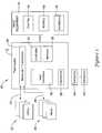
- FIG. 1shows an illustrative but non-limiting HVAC control system.
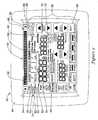
- FIG. 2shows an illustrative but non-limiting example of a thermostat of FIG. 1 ;
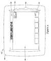
- FIG. 3shows an illustrative thermostat operating in accordance with its programming
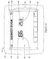
- FIG. 4shows the illustrative thermostat of FIG. 3 after the current energy demand and/or current energy cost has reached a critical level
- FIG. 5shows the illustrative thermostat of FIG. 3 displaying a first stored or received message
- FIGS. 6-7shows the illustrative thermostat of FIG. 5 displaying a second stored or received message
- FIG. 8shows the illustrative thermostat of FIG. 3 displaying a “Please conservee” message received from a utility
- FIG. 9shows the illustrative thermostat of FIG. 3 displaying a “Storm Warning” message received from a utility or other source;
- FIG. 10show the illustrative thermostat of FIG. 3 displaying information related to electrical consumption including historical electrical consumption information
- FIG. 11show the illustrative thermostat of FIG. 3 displaying information related to electrical costs including historical electrical cost information
- FIG. 12show the illustrative thermostat of FIG. 3 displaying information related to water usage including historical water usage information
- FIG. 13show the illustrative thermostat of FIG. 3 displaying information related to water usage costs including historical water usage cost information;
- FIG. 14show the illustrative thermostat of FIG. 3 displaying information related to gas usage including historical gas usage information
- FIG. 15show the illustrative thermostat of FIG. 3 displaying information related to gas usage costs including historical gas usage cost information;
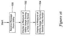
- FIG. 16is a flow diagram of an illustrative method in accordance with the present invention.
- FIG. 17is a flow diagram of another illustrative method in accordance with the present invention.
- FIG. 1shows an illustrative but non-limiting HVAC control system 10 .
- the illustrative HVAC control system 10includes a thermostat 12 that may be adapted to interact with and control HVAC equipment 14 .
- HVAC equipment 14may include one or more of cooling equipment 16 , heating equipment 18 and/or ventilation equipment 20 .
- cooling equipment 16 and heating equipment 18may, for example, be combined in a forced air system, or perhaps a heat pump system, particularly in residential and/or light commercial applications.
- one or more of cooling equipment 16 , heating equipment 18 and/or ventilation equipment 20may be distinct systems controlled by thermostat 12 .
- thermostat 12may represent two or more distinct thermostats, each controlling different equipment within HVAC equipment 14 , and or different zones within a structure.
- thermostat 12may be adapted to interact and/or communicate with a utility 22 .
- Utility 22may represent a utility company or another entity that produces or otherwise provides an energy source such as electricity, natural gas and the like, or provides another utility such as water and/or sewer service.
- Utility 22may represent a utility company or other entity that provides a source of hot water that can be used for heating and/or any other desired use.
- Utility 22may provide hot water from a geothermal source, or by heating water using biomass or even microwave energy.
- thermostat 12may receive signals from utility 22 via a communication network 24 .
- Communication network 24may include wireless communication between utility 22 and thermostat 12 , using radio frequencies and the like.
- communication network 24may represent a hard-wired communication network between utility 22 and thermostat 12 , such as copper wiring, coaxial cable, CAT 5 cable, fiber optics, and the like.
- communication network 24may represent signals sent over the power lines themselves.
- part of communication network 24may be a wired and another part may be wireless. More generally, communication network 24 may be any suitable communication path between utility 22 or the like and thermostat 12 .
- thermostat 12may receive information from utility 22 pertaining to utility usage, utility usage history, current and/or historical rate information, and the like. Alternatively, or in addition, thermostat 12 may receive information from meter 26 pertaining to utility usage, utility usage history, current and/or historical rate information, and the like. In some cases, thermostat 12 may receive information from utility 22 and/or meter 26 pertaining to a current electrical rate, say in cents per kilowatt-hour. In some instances, thermostat 12 may receive information regarding a remaining balance on a prepaid account, or perhaps monthly garbage and/or sewer charges.
- Utility 22 and/or meter 26may, for example provide information to thermostat 12 regarding a measure of utility usage.
- the measure of utility usagemay be related to current utility costs over a designated period of time (e.g. over a past year, a past month, a past week, a past day, a past hour, etc.), i.e., a current electrical cost over a designated period of time, a current gas cost over a designated period of time, a current water cost of a designated period or time and the like.
- a measure of utility usagemay include a quantity of utility usage, and thus utility 22 may provide thermostat 12 with information pertaining to how much energy (e.g.
- KWHwhich are kilowatt-hours
- KWHwhich are kilowatt-hours
- a designated period of timee.g. over a past year, a past month, a past week, a past day, a past hour, schedule period, etc.
- utility 22 and/or meter 26may provide messages relating to utility usage.
- utility 22may provide, via communication network 24 , one or more messages intended for a homeowner, facilities manager or the like.
- utility 22may provide one or more messages that permit or instruct thermostat 12 to display suggestions on how to save energy, water or other resource.
- thermostat 12may display one or more messages suggesting that the homeowner or facilities manager conserve energy by changing a temperature set point, or perhaps suggesting that they wait and run energy intensive appliances later in the day, when utility demand may be lower.
- Utility 22may, in some instances, provide one or more messages that permit or instruct thermostat 12 to display information pertaining to current or expected weather, current or expected energy demand, current or expected pricing tiers, etc.
- utility 22 and/or meter 26may provide one or more messages that cause thermostat 12 to display information relating to utility billing. This may include utility billing history, current utility billing rates and/or current utility costs, and the like.
- Thermostat 12may display information pertaining to a measure of utility usage during a first time period (e.g. a designated month such as the current month) and information pertaining to a measure of utility usage during a second time period (e.g. the designated month one year ago) that is different from the first time period. While not required, the first time period may occur temporally before the second time period.
- controller 34may compute a measure of utility usage that is consumed by the HVAC system of the building or other structure by monitoring the on-time of one or more HVAC system components 16 , 18 and/or 20 .
- the first time period and the second time periodmay each, independently, be any desired length of time, and may be temporally separated by any desired time interval. In some cases, the first time period may immediately precede the second time period. The first time period may, if desired, be one or more months before the second time period. In some cases, the first time period may be about a year or more prior to the second time period.
- the first time period and the second time periodmay each correspond to a one week ( 168 hours) time period, and the first time period may correspond to an immediately preceding week relative to the second time period. In some instances, the first time period and the second time period may each correspond to a one month time period. The first time period may be a one month time period that immediately precedes the second time period. In some cases, the first time period (e.g. June 2006) may be a one month time period that is about one year prior to the second time period (e.g. June 2007).
- the indication of the measure of utility usage that is displayed for the first time periodmay include an indication of the cost of utility usage during the first time period
- the indication of the measure of utility usage that is displayed for the second time periodincludes an indication of the cost of utility usage during the second period of time.
- the indication of the measure of utility usage that is displayed for the first time periodincludes an indication of the quantity of utility usage during the first period of time
- the indication of the measure of utility usage that is displayed for the second time periodinclude an indication of the quantity of utility usage during the second period of time.
- thermostat 12may be adapted to interact and/or communicate with a meter 26 over a communication line 28 .
- Meter 26may, for example, be adapted to measure and/or regulate a flow of energy or other resource (e.g. water) from utility 22 , and may also provide thermostat 12 with usage information via a wireless, wired, optical, or any other suitable communication path. In some instances, although direct communication therebetween is not expressly shown in FIG. 1 , meter 26 may provide utility 22 with usage information.
- Communication line 28may represent wireless communication between meter 26 and thermostat 12 .
- communication line 28may represent a hard-wired line between meter 26 and thermostat 12 , such as copper wiring, coaxial cable, CAT 5 cable, fiber optic cable, and the like.
- meter 26may also communicate with utility 22 , and may receive utility rate information and the like from utility 22 , but this is not required in all embodiments.
- thermostat 12may include a receiver and/or transceiver 30 that permits thermostat 12 to communicate with utility 22 via communication network 24 and/or to communicate with meter 26 via communication line 28 .
- communication network 24 and/or communication line 28may be wired or wireless
- communication network 24may, for example, include a wireless paging system
- receiver and/or transceiver 30may be a load control receiver that uses, for example, a 900 MHz paging technology such as the FLEX® paging technology available from Motorola.
- One such load control receiveris available from Cannon Technologies, located in Wayzata, Minn., although it is contemplated that any suitable communication equipment may be used, as desired.
- Thermostat 12may include a user interface 32 that may be adapted to accept information from a user as well as to provide information to the user.
- user interface 32may include a liquid crystal display (LCD) as well as a keypad or similar entry device.
- user interface 32may include a touch screen LCD that provides both functions.
- Thermostat 12may include a controller 34 that is adapted to oversee the aforementioned communications between thermostat 12 and utility 22 and/or meter 26 . Controller 34 may regulate information that is solicited and/or displayed on user interface 32 . Controller 34 may be adapted to implement a control algorithm that is adapted to at least partially control one or more components of HVAC equipment 14 . Thermostat 12 may include a memory block 36 that can be used to store operating parameters, utility usage history and the like.
- Thermostat 12may include a sensor 38 , which may be located within thermostat 12 as well as one or more external sensors 40 , as desired.
- sensors 38 and 40may be any type of sensor, or may represent multiple sensors, such as temperature sensors, humidity sensors and the like.
- External sensors 40may be hard wired to thermostat 12 , or may communicate wirelessly, as desired.
- FIG. 2shows an illustrative but non-limiting example of a thermostat 42 that may be considered as representing thermostat 12 ( FIG. 1 ), but showing additional detail regarding user interface 32 .
- Thermostat 42includes a thermostat housing 44 and an LCD display 46 that is visible from outside thermostat housing 44 .
- Thermostat housing 44may be formed of any suitable material and having any suitable dimensions. In some cases, thermostat housing 44 is stamped or molded from a polymeric material. In some cases, LCD display 46 is a touch screen LCD, but this is not required in all embodiments.
- first region 48includes an array of pixels 52 that are arranged into a plurality of rows and a plurality of columns to form an array of pixels that is suitable for displaying alphanumeric characters such as text in a dot matrix format.
- one or more of pixels 52may be square or round fixed segment pixels.
- first region 48may include an array of pixels 52 that are arranged into 7 rows and a total of 125 columns. To more clearly illustrate the individual pixels, pixels 52 are schematically illustrated in FIG. 2 as unlit.
- First region 48may be constructed using either fixed segment type LCD display or a graphic type LCD display.
- first region 48is constructed as a fixed segment LCD display, a number of relatively small fixed segments dots are provided, and in some cases, may be arranged into character blocks, with each character block having, for example, 5 ⁇ 7 dots. In some cases, each character block can be addressed separately and can form numbers, letters and a limited number of symbols. In other cases, each fixed segment dot can be addressed separately.
- first region 48is constructed as a graphics type LCD display, a relatively larger number of pixels are arranged in rows and columns, and each pixel can typically be individually addressed.
- first region 48may include or be formed as fixed segment LCD display, and may include a total of 25 5 ⁇ 7 characters, for a total of 875 individual pixels 52 .
- Each pixel 52may be square and may be 0.5 millimeters by 0.5 millimeters in size. There may be a small gap between adjacent pixels 52 . In some cases, there may be a 0.05 millimeter gap between adjacent pixels 52 .
- These pixels 52may be formed as part of the fixed segment mask used in fabricating the fixed segment LCD display.
- first region 48may be used to display messages and other similar text.
- Controller 34may be coupled to user interface 32 and may be adapted to display a message including two or more text characters in first region 48 using the array of fixed segment pixels 52 . If desired, controller 34 may be adapted to scroll messages across at least part of first region 48 . This may be useful in displaying messages that are too long to simultaneously fit in their entirety within first region 48 . Scrolling may also be useful in attracting attention to messages being displayed within first region 48 .
- a messagemay be flashed, i.e., repeatedly turned on and off, within first region 48 to draw attention to the particular message.
- display 46may include a left arrow icon 54 and/or a right arrow icon 56 , which may be used to scroll through a long message, or perhaps to scroll through multiple messages.
- Left arrow icon 54 and right arrow icon 56may be constructed as fixed segment icons, and may not be considered part of first region 48 , even though they are located within an upper portion of display 46 .
- pressing right arrow icon 56may cause controller 34 ( FIG. 1 ) to display another message, if another message is available, or to cause a message to scroll. Pressing left arrow icon 54 may cause controller 34 to display a previous message or to cause a message to scroll.
- Second region 50 of user display 46may include a plurality of fixed segment graphical icons. At least some of the fixed segment graphical icons within second region 50 may be or may include a word, a perimeter boundary and/or a word within a perimeter boundary. In some instances, LCD display 46 is a touch screen LCD, and one or more of the fixed segment graphical icons may coincide with one or more touch sensitive buttons.
- second region 50may include a message icon 58 .
- controller 34FIG. 1
- the “VIEW” textmay be formed as part of a fixed segment graphical icon, if desired.
- Message icon 58may coincide with a touch sensitive button or portion of LCD display 46 .
- message icon 58may include a fixed segment perimeter boundary 59 .
- Pressing message icon 58may cause controller 34 to proceed with displaying and/or scrolling one or more messages within first region 48 of display 46 using the array of fixed segment pixels 52 .
- the “DELETE” text within message icon 58may be illuminated, although this is not required. Pressing message icon 58 at this stage may cause controller 34 to delete the message that has been displayed or is currently being displayed.
- Second region 50may include an “EXIT” icon 60 . Pressing EXIT icon 60 instead of message icon 58 may cause controller 34 to return to a previous screen without deleting the displayed message or messages. Example messages are shown and discussed with respect to subsequent Figures.
- second region 50 of display 46may include a set 62 of fixed segments that are configured to display numbers.
- set 62may be configured to display utility usage data including utility usage quantity data and/or utility usage cost data.
- set 62may include a total of five fixed segment numbers 64 , with each fixed segment number 64 having a total of seven distinct bar segments 66 .
- second region 50 of display 46may include a set 68 of fixed segments that are configured to display numbers.
- set 68may be configured to display historical utility usage data including historical utility usage quantity and/or historical utility usage cost data.
- set 68may include a total of five fixed segment numbers 70 , with each fixed segment number 70 having a total of seven distinct bar segments 72 .
- second region 50 of display 46may include a TIER icon 74 that may include one or more of a CRITICAL fixed segment 76 , a HIGH fixed segment 78 , a MEDIUM fixed segment 80 and/or a LOW fixed segment 82 .
- utility 22FIG. 1
- TIER icon 74may not be illuminated.
- controller 34may illuminate CRITICAL fixed segment 76 .
- a SAVING icon 84may be illuminated or even flash indicating that controller 34 has altered a temperature set point in accordance with the energy demand information provided by utility 22 ( FIG. 1 ).
- SAVING icon 84may be illuminated irrespective of the current tier level.
- utility 22may, in response to energy demand and/or energy cost data, may determine how temperature set points are to be altered.
- a customermay, for example, sign a contract permitting utility 22 to alter temperature set points and/or to determine temperature differentials as necessary and/or appropriate. If utility 22 determines that a particular tier level has been reached, utility 22 may send a signal to thermostat 42 temporarily altering a temperature set point, either by providing a temporary temperature set point or by providing a temperature differential that can be applied to the temperature set point specified by the current schedule under which thermostat 42 is otherwise operating.
- the contractmay permit utility 22 to send a signal to thermostat 42 instructing thermostat 42 to shut down HVAC equipment 14 ( FIG. 1 ) for a length of time that may be predetermined and/or may be calculated based, for example, on current energy demand and/or current energy rates.
- utility 22may provide a signal to thermostat 42 instructing thermostat 42 to change to a temporary temperature set point.
- the temporary set pointmay vary, depending on the current energy tier.
- utility 22may suggest or require, based at least in part on the contract signed by the owner, a heating temperature set point of 70° F. for a low energy cost, 65° F. for a medium energy cost, 60° F. for a high energy cost, and 50° F. for a critical energy cost.
- Utility 22may suggest or require, based at least in part on the contract, a cooling temperature set point of 72° F. for a low energy cost, 77° F. for a medium energy cost, 82° F. for a high energy cost, and 86° F. for a critical energy cost.
- These temperaturesare merely illustrative and are not intended to limit or define in any way or manner.
- utility 22may provide thermostat 42 with the heating and cooling temperature set point values corresponding to each tier level.
- Controller 34may issue a control signal to HVAC equipment 14 for operating cooling equipment 16 and/or heating equipment 18 when the temperature is different than the temperature set point associated with the acceptable energy cost level.
- the control signalmay issue control information for operating heating equipment 18 when the temperature fell to 60° F. or below.
- the control signalwould issue control information for operating cooling equipment 16 when the temperature rose to or above 82° F.
- the receiver and/or transceiver 30may receive information from the utility(s) for an energy (and/or water) bill for usage of energy (and/or water) during a time period. In some cases, the user may authorize payment of the energy (and/or water) bill and have the authorization transmitted to utility 22 via the thermostat 12 .
- utility 22may send a signal instructing thermostat 42 to temporarily change its temperature set point by a particular temperature differential that depends on tier level
- utility 22may provide a signal including a temperature differential or offset of 0° F. for a low energy cost, a temperature differential or offset of 2° F. for a medium energy cost, a temperature differential or offset of 6° F. for a high energy cost and a temperature differential or offset of 10° F. for a high energy costs.
- thermostat 42may temporarily operate with a temperature set point of 58° F. (68° F.-10° F.). If, for example, the current temperature set point for cooling is set at 76° F. and the energy demand reaches the high level, thermostat 42 may temporarily operate with a temperature set point of 86° F. (76° F.+10° F.).
- the ownermay be able to override the temporary temperature set points provided by the utility.
- the ownermay not be permitted to make any changes, and in fact thermostat 42 may be instructed to not accept set point changes while utility 22 is providing a temporary temperature set point and/or a temperature differential to thermostat 42 .
- thermostat 42may program thermostat 42 with information pertaining to how temperature set points are to be altered in response to various energy demand and/or energy cost levels provided by utility 22 .
- setback information that has been programmed into thermostat 42may be based at least in part upon which time period (WAKE, LEAVE, RETURN, SLEEP) thermostat 42 is currently operating under.
- FIG. 3shows the illustrative thermostat 42 operating in accordance with its programming.
- controller 34FIG. 1
- controller 34On second region 50 of display 46 , controller 34 ( FIG. 1 ) is displaying a current inside temperature value 86 and a current temperature set point 88 . If message icon 58 is blinking or otherwise illuminated, pressing message icon 58 may cause one or more messages to be displayed, as will be illustrated subsequently.
- the illustrative thermostat 42may continue to operate in accordance with its schedule, as indicated by the “Following Schedule” fixed segment icon 90 . It can be seen that as the temperature set point 88 is higher than the current temperature value 86 , the heat is currently operational.
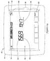
- TIER icon 74is indicating that the current energy demand and/or current energy cost has reached a critical level 76 . While current inside temperature value 86 remains constant at 66° F., it can be seen that the temperature set point 88 has dropped from the 72° F. value shown in FIG. 3 to a savings temperature value of 58° F., and the heat has thus shut off. In some cases, controller 34 monitors the communication with utility 22 . In some cases, if the communication is broken or otherwise not functioning properly for some reason, thermostat 42 may return to its normal schedule until such time as communication is reestablished.
- message icon 58is blinking or is otherwise illuminated.
- pressing message icon 58will cause controller 34 ( FIG. 1 ) to display stored or received messages, as shown in FIG. 5 .
- First region 48 of display 46can be seen as displaying a message “Good Morning!”. Because there is more than one message to display (two, in this example), the message includes “1 ⁇ 2” in front of the message, and right arrow icon 56 is illuminated. Pressing right arrow icon 56 may cause controller 34 to display the second message, as shown in FIGS. 6 and 7 . It can be seen that once the message has been viewed, message icon 58 changes from illuminating the VIEW fixed segment icon to illuminating the DELETE fixed segment icon.
- the second messageis “2 Honeywell UtilityPRO Helps You to Save Energy”, which is too large to display within the 25 character blocks forming first region 48 .
- controller 34FIG. 1
- first region 48includes “2 Honeywell UtilityPRO He”, which is the first 25 characters of the message while in FIG. 7 , first region 48 includes “0 Helps You to Save Energy”, which represents the last 25 characters of the message.
- screen capturesillustrating how text fits within first region 48 . While the message is broken over two Figures, it will be understood that the message actually scrolls smoothly across first region 48 of display 46 . In some cases, it is contemplated that text may be scrolled vertically, rather than horizontally.
- left arrow icon 54is illuminated, so that a user may move back to the previous message. In some cases, if only one message is available or otherwise appropriate for display, neither left arrow icon 54 nor right arrow icon 56 may be illuminated.
- first region 48 of display 46may, in response to a signal from utility 22 ( FIG. 1 ), display a message reading “Please conservee!” This message may be displayed when, for example, the utility demand is high or expected to be high. Similar messages may suggest that the person refrain from running energy intensive appliances such as washing machines until the energy demand drops.
- FIG. 9Another illustrative message is seen in FIG. 9 , in which first region 48 of display 46 displays a message reading “Storm Warning”, perhaps in response to utility 22 forwarding a signal from the local weather authorities, or perhaps the local weather authorities are equipped to broadcast a warning signal directly to receiver and/or transceiver 30 ( FIG. 1 ).
- a tornado warning messagemay only be sent to those thermostats that are within the geographic region that is currently under a tornado warning.
- an ozone or UV warning messagemay only be sent to those thermostats that are within the geographic region that is currently experiencing high ozone or UV.
- a messagemay be directed to only those thermostats that correspond to those customers (e.g. a unique message to a particular group of customers).
- a water utilitymay have certain restrictions on water usage, such as limiting the watering of lawns to ever other day.
- the water utilitymay send a message to the thermostat to notify the user of the water restrictions.
- the water utilitymay send a message indicating that watering of lawns is prohibited for the customer on a particularly day (e.g. today) or during some other time period.
- thermostat 42may be adapted to provide a user with information regarding current and/or historical energy consumption data and corresponding energy costs.
- FIGS. 10-15illustrative this feature.
- lower region 50 of display 46includes a USAGE icon 92 .
- pressing USAGE icon 92brings the user to the screen shown in FIG. 10 .
- controller 34( FIG. 1 ) is displaying information pertaining to electrical consumption.
- controller 34is instructing first region 48 of display 46 to display “ELECTRICITY IN KWH”, so that the user can put into context the numerical data displayed within second region 50 of display 46 using set 62 of fixed segments and set 68 of fixed segments.
- Set 62is displaying a value for the amount of electricity used thus far this month while set 68 is being used to display a value for the corresponding time period last year.
- Fixed segment icon 94informs the user of the current time period while fixed segment icon 96 informs the user of the corresponding historical time period.
- other time periodsmay also be chosen or otherwise selected or displayed, as desired.
- FIG. 11Pressing right arrow icon 56 brings the user to FIG. 11 , in which controller 34 ( FIG. 1 ) is displaying information regarding electrical costs, while instead pressing EXIT button 60 would return the user to FIG. 3 .
- first region 48 of display 46now reads “ELECTRICITY BILL”.
- Fixed segment icon 98representing a dollar sign, provides additional context for the information being displayed. In some cases, fixed segment icon 98 may be omitted, if desired.
- Set 62is being used by controller 34 to display the electrical bill to date for the month while set 68 is being used by controller 34 to provide the corresponding historical data.
- Pressing left arrow icon 54would return the user to the screen shown in FIG. 10 while pressing right arrow icon 56 will bring the user to the screen shown in FIG. 12 .
- Pressing EXIT button 60would return the user to FIG. 3 .
- controller 34( FIG. 1 ) is displaying information pertaining to water consumption.
- controller 34is instructing first region 48 of display 46 to display “WATER USAGE IN KGAL”, so that the user can put into context the numerical data displayed within second region 50 of display 46 using set 62 of fixed segments and set 68 of fixed segments.
- Set 62is displaying a value for the amount of water used thus far this month while set 68 is being used to display a value for the corresponding time period last year.
- Fixed segment icon 94informs the user of the current time period while fixed segment icon 96 informs the user of the corresponding historical time period. As discussed above, other time periods may also be chosen or otherwise selected or displayed.
- FIG. 13Pressing right arrow icon 56 brings the user to FIG. 13 , in which controller 34 ( FIG. 1 ) is displaying information regarding water costs, while instead pressing EXIT button 60 would return the user to FIG. 3 .
- first region 48 of display 46now reads “WATER BILL”.
- Fixed segment icon 98representing a dollar sign, provides additional context for the information being displayed. In some cases, fixed segment icon 98 may be omitted, if desired.
- Set 62is being used by controller 34 to display the water bill to date for the month while set 68 is being used by controller 34 to provide the corresponding historical data.
- Pressing left arrow icon 54would return the user to the screen shown in FIG. 12 while pressing right arrow icon 56 will bring the user to the screen shown in FIG. 14 .
- Pressing EXIT button 60would return the user to FIG. 3 .
- controller 34( FIG. 1 ) is displaying information pertaining to gas consumption.
- controller 34is instructing first region 48 of display 46 to display “GAS USAGE IN CCF”, so that the user can put into context the numerical data displayed within second region 50 of display 46 using set 62 of fixed segments and set 68 of fixed segments.
- Set 62is displaying a value for the amount of gas used thus far this month while set 68 is being used to display a value for the corresponding time period last year.
- Fixed segment icon 94informs the user of the current time period while fixed segment icon 96 informs the user of the corresponding historical time period. As discussed above, other time periods may also be chosen or otherwise selected or displayed.
- FIG. 15Pressing right arrow icon 56 brings the user to FIG. 15 , in which controller 34 ( FIG. 1 ) is displaying information regarding gas costs, while instead pressing EXIT button 60 would return the user to FIG. 3 ,
- first region 48 of display 46now reads “GAS BILL”.
- Fixed segment icon 98representing a dollar sign, provides additional context for the information being displayed. In some cases, fixed segment icon 98 may be omitted, if desired.
- Set 62is being used by controller 34 to display the water bill to date for the month while set 68 is being used by controller 34 to provide the corresponding historical data.
- Pressing left arrow icon 54would return the user to the screen shown in FIG. 14 while pressing right arrow icon 56 will return the user to the screen shown in FIG. 10 , unless thermostat 42 is equipped to display additional consumption or cost data.
- Pressing EXIT button 60would return the user to FIG. 3 .
- FIGS. 16 and 17are flow diagrams illustrating methods that may be carried out using thermostat 42 ( FIG. 2 ).
- controlbegins at block 100 , where thermostat 42 receives a message from utility 22 ( FIG. 1 ).
- the message received from utility 22may be related to energy demand, current and/or past energy costs, energy conservation, weather alerts, promotional and/or advertisements and the like.
- controller 34FIG. 1
- controller 34displays on display 46 an indication of a measure of utility usage during a first time period.
- controller 34displays on display 46 an indication of a measure of utility usage during a second time period. In some cases, the first time period may predate the second time period, but this is not required.
- controlbegins at block 100 , where thermostat 42 ( FIG. 2 ) receives a message from utility 22 ( FIG. 1 ).
- controller 34( FIG. 1 ) displays on display 46 an indication of a measure of utility usage during a period of time.
- Controlpasses to block 108 , where controller 34 displays on display 46 one or more display messages that are related to the message received from utility 22 . These messages may pertain to energy demand, current energy costs, energy conservation, weather alerts, advertisements and the like.
- the indication of the measure of utility usage during the period of timemay be displayed on display 46 at the same time or nearly the same time as the one or more messages are displayed on display 46 . In some cases, they are not displayed simultaneously.
Landscapes
- Engineering & Computer Science (AREA)
- Chemical & Material Sciences (AREA)
- Combustion & Propulsion (AREA)
- Mechanical Engineering (AREA)
- General Engineering & Computer Science (AREA)
- Human Computer Interaction (AREA)
- Physics & Mathematics (AREA)
- General Physics & Mathematics (AREA)
- Automation & Control Theory (AREA)
- Air Conditioning Control Device (AREA)
Abstract
Description
Claims (18)
Priority Applications (3)
| Application Number | Priority Date | Filing Date | Title |
|---|---|---|---|
| US11/770,634US7845576B2 (en) | 2007-06-28 | 2007-06-28 | Thermostat with fixed segment display having both fixed segment icons and a variable text display capacity |
| PCT/US2008/068104WO2009006133A1 (en) | 2007-06-28 | 2008-06-25 | Thermostat with messaging capability on display |
| CN200880022108ACN101689058A (en) | 2007-06-28 | 2008-06-25 | Has the thermostat that on display, transmits message capability |
Applications Claiming Priority (1)
| Application Number | Priority Date | Filing Date | Title |
|---|---|---|---|
| US11/770,634US7845576B2 (en) | 2007-06-28 | 2007-06-28 | Thermostat with fixed segment display having both fixed segment icons and a variable text display capacity |
Publications (2)
| Publication Number | Publication Date |
|---|---|
| US20090001182A1 US20090001182A1 (en) | 2009-01-01 |
| US7845576B2true US7845576B2 (en) | 2010-12-07 |
Family
ID=40159185
Family Applications (1)
| Application Number | Title | Priority Date | Filing Date |
|---|---|---|---|
| US11/770,634Active2029-02-11US7845576B2 (en) | 2007-06-28 | 2007-06-28 | Thermostat with fixed segment display having both fixed segment icons and a variable text display capacity |
Country Status (1)
| Country | Link |
|---|---|
| US (1) | US7845576B2 (en) |
Cited By (97)
| Publication number | Priority date | Publication date | Assignee | Title |
|---|---|---|---|---|
| US20090092062A1 (en)* | 2007-10-05 | 2009-04-09 | Edward Lee Koch | Critical resource notification system and interface device |
| US20090143879A1 (en)* | 2007-11-30 | 2009-06-04 | Honeywell International, Inc. | Hvac controller with parameter clustering |
| US20090158188A1 (en)* | 2007-12-14 | 2009-06-18 | Honeywell International Inc. | Configurable wall module system |
| US20110106316A1 (en)* | 2011-01-12 | 2011-05-05 | David Scott Drew | Apparatus and method for determining load of energy consuming appliances within a premises |
| USD638373S1 (en)* | 2010-07-30 | 2011-05-24 | Greenwave Reality, Pte Ltd. | Display module |
| US20120029725A1 (en)* | 2010-12-16 | 2012-02-02 | General Electric Company | Smart hybrid thermostat |
| US20120023976A1 (en)* | 2010-07-28 | 2012-02-02 | Younggeul Kim | Air conditioner and method for controlling the same |
| US20120169511A1 (en)* | 2011-01-04 | 2012-07-05 | Greenwave Reality, Pte Ltd. | Multi-Mode Display |
| US8280536B1 (en) | 2010-11-19 | 2012-10-02 | Nest Labs, Inc. | Thermostat user interface |
| US8560128B2 (en) | 2010-11-19 | 2013-10-15 | Nest Labs, Inc. | Adjusting proximity thresholds for activating a device user interface |
| US8572230B2 (en) | 2009-07-17 | 2013-10-29 | Honeywell International Inc. | System for using attributes to deploy demand response resources |
| US8626354B2 (en) | 2011-01-28 | 2014-01-07 | Honeywell International Inc. | Approach for normalizing automated demand response events in energy management control systems |
| US8630740B2 (en) | 2011-10-21 | 2014-01-14 | Nest Labs, Inc. | Automated control-schedule acquisition within an intelligent controller |
| US8630744B2 (en) | 2011-01-28 | 2014-01-14 | Honeywell International Inc. | Management and monitoring of automated demand response in a multi-site enterprise |
| US8667132B2 (en) | 2009-07-17 | 2014-03-04 | Honeywell International Inc. | Arrangement for communication about and management of a resource using a mobile device |
| US8671191B2 (en) | 2009-07-17 | 2014-03-11 | Honeywell International Inc. | Installation system for demand response resources |
| US8671167B2 (en) | 2009-07-17 | 2014-03-11 | Honeywell International Inc. | System for providing demand response services |
| US8676953B2 (en) | 2009-07-17 | 2014-03-18 | Honeywell International Inc. | Use of aggregated groups for managing demand response resources |
| WO2012092622A3 (en)* | 2010-12-31 | 2014-04-10 | Nest Labs, Inc. | Inhibiting deleterious control coupling in an enclosure having multiple hvac regions |
| US8708242B2 (en) | 2012-09-21 | 2014-04-29 | Nest Labs, Inc. | Thermostat system with software-repurposable wiring terminals adaptable for HVAC systems of different ranges of complexity |
| US8727611B2 (en) | 2010-11-19 | 2014-05-20 | Nest Labs, Inc. | System and method for integrating sensors in thermostats |
| US8782190B2 (en) | 2009-07-17 | 2014-07-15 | Honeywell International, Inc. | Demand response management system |
| US8843239B2 (en) | 2010-11-19 | 2014-09-23 | Nest Labs, Inc. | Methods, systems, and related architectures for managing network connected thermostats |
| US8850348B2 (en) | 2010-12-31 | 2014-09-30 | Google Inc. | Dynamic device-associated feedback indicative of responsible device usage |
| US20140316581A1 (en)* | 2010-11-19 | 2014-10-23 | Nest Labs, Inc. | Systems and Methods for Energy-Efficient Control of an Energy-Consuming System |
| US20140319235A1 (en)* | 2013-04-30 | 2014-10-30 | Honeywell International Inc. | User interface for an hvac controller |
| US8893032B2 (en) | 2012-03-29 | 2014-11-18 | Google Inc. | User interfaces for HVAC schedule display and modification on smartphone or other space-limited touchscreen device |
| US8918219B2 (en) | 2010-11-19 | 2014-12-23 | Google Inc. | User friendly interface for control unit |
| RU2547217C2 (en)* | 2013-06-13 | 2015-04-10 | Валерий Борисович Бабанин | Serial interface for controlling multibit character display |
| US9046414B2 (en) | 2012-09-21 | 2015-06-02 | Google Inc. | Selectable lens button for a hazard detector and method therefor |
| USRE45574E1 (en) | 2007-02-09 | 2015-06-23 | Honeywell International Inc. | Self-programmable thermostat |
| US9092039B2 (en) | 2010-11-19 | 2015-07-28 | Google Inc. | HVAC controller with user-friendly installation features with wire insertion detection |
| US9092040B2 (en) | 2010-11-19 | 2015-07-28 | Google Inc. | HVAC filter monitoring |
| US9116529B2 (en) | 2011-02-24 | 2015-08-25 | Google Inc. | Thermostat with self-configuring connections to facilitate do-it-yourself installation |
| US9115908B2 (en) | 2011-07-27 | 2015-08-25 | Honeywell International Inc. | Systems and methods for managing a programmable thermostat |
| US9124535B2 (en) | 2009-07-17 | 2015-09-01 | Honeywell International Inc. | System for using attributes to deploy demand response resources |
| US9137050B2 (en) | 2009-07-17 | 2015-09-15 | Honeywell International Inc. | Demand response system incorporating a graphical processing unit |
| US9153001B2 (en) | 2011-01-28 | 2015-10-06 | Honeywell International Inc. | Approach for managing distribution of automated demand response events in a multi-site enterprise |
| US9175871B2 (en) | 2011-10-07 | 2015-11-03 | Google Inc. | Thermostat user interface |
| US9213342B2 (en) | 2011-03-28 | 2015-12-15 | Emerson Electric Co. | Wireless control of a heating or cooling unit |
| US9298196B2 (en) | 2010-11-19 | 2016-03-29 | Google Inc. | Energy efficiency promoting schedule learning algorithms for intelligent thermostat |
| US20160154576A1 (en)* | 2014-06-16 | 2016-06-02 | Braeburn Systems, Llc | Graphical highlight for programming a control |
| US9389850B2 (en) | 2012-11-29 | 2016-07-12 | Honeywell International Inc. | System and approach to manage versioning of field devices in a multi-site enterprise |
| US9453655B2 (en) | 2011-10-07 | 2016-09-27 | Google Inc. | Methods and graphical user interfaces for reporting performance information for an HVAC system controlled by a self-programming network-connected thermostat |
| US9552002B2 (en) | 2010-11-19 | 2017-01-24 | Google Inc. | Graphical user interface for setpoint creation and modification |
| US9607787B2 (en) | 2012-09-21 | 2017-03-28 | Google Inc. | Tactile feedback button for a hazard detector and fabrication method thereof |
| US9665078B2 (en) | 2014-03-25 | 2017-05-30 | Honeywell International Inc. | System for propagating messages for purposes of demand response |
| US9691076B2 (en) | 2013-07-11 | 2017-06-27 | Honeywell International Inc. | Demand response system having a participation predictor |
| US9702582B2 (en) | 2015-10-12 | 2017-07-11 | Ikorongo Technology, LLC | Connected thermostat for controlling a climate system based on a desired usage profile in comparison to other connected thermostats controlling other climate systems |
| US9818073B2 (en) | 2009-07-17 | 2017-11-14 | Honeywell International Inc. | Demand response management system |
| US9890971B2 (en) | 2015-05-04 | 2018-02-13 | Johnson Controls Technology Company | User control device with hinged mounting plate |
| US9890970B2 (en) | 2012-03-29 | 2018-02-13 | Google Inc. | Processing and reporting usage information for an HVAC system controlled by a network-connected thermostat |
| US9952573B2 (en) | 2010-11-19 | 2018-04-24 | Google Llc | Systems and methods for a graphical user interface of a controller for an energy-consuming system having spatially related discrete display elements |
| US9965984B2 (en) | 2012-12-05 | 2018-05-08 | Braeburn Systems, Llc | Climate control panel with non-planar display |
| US9989937B2 (en) | 2013-07-11 | 2018-06-05 | Honeywell International Inc. | Predicting responses of resources to demand response signals and having comfortable demand responses |
| US10055323B2 (en) | 2014-10-30 | 2018-08-21 | Braeburn Systems Llc | System and method for monitoring building environmental data |
| US10054964B2 (en) | 2012-05-07 | 2018-08-21 | Google Llc | Building control unit method and controls |
| US10078319B2 (en) | 2010-11-19 | 2018-09-18 | Google Llc | HVAC schedule establishment in an intelligent, network-connected thermostat |
| US10162327B2 (en) | 2015-10-28 | 2018-12-25 | Johnson Controls Technology Company | Multi-function thermostat with concierge features |
| US10241527B2 (en) | 2010-11-19 | 2019-03-26 | Google Llc | Thermostat graphical user interface |
| US10317919B2 (en) | 2016-06-15 | 2019-06-11 | Braeburn Systems Llc | Tamper resistant thermostat having hidden limit adjustment capabilities |
| US10317867B2 (en) | 2016-02-26 | 2019-06-11 | Braeburn Systems Llc | Thermostat update and copy methods and systems |
| US10318266B2 (en) | 2015-11-25 | 2019-06-11 | Johnson Controls Technology Company | Modular multi-function thermostat |
| US20190187632A1 (en)* | 2011-09-30 | 2019-06-20 | Johnson Controls Technology Company | Cascaded systems and methods for controlling energy use during a demand limiting period |
| US10346931B2 (en) | 2013-07-11 | 2019-07-09 | Honeywell International Inc. | Arrangement for communicating demand response resource incentives |
| US10346275B2 (en) | 2010-11-19 | 2019-07-09 | Google Llc | Attributing causation for energy usage and setpoint changes with a network-connected thermostat |
| US10356573B2 (en) | 2014-10-22 | 2019-07-16 | Braeburn Systems Llc | Thermostat synchronization via remote input device |
| US10410300B2 (en) | 2015-09-11 | 2019-09-10 | Johnson Controls Technology Company | Thermostat with occupancy detection based on social media event data |
| US10423142B2 (en) | 2015-02-10 | 2019-09-24 | Braeburn Systems Llc | Thermostat configuration duplication system |
| US10430056B2 (en) | 2014-10-30 | 2019-10-01 | Braeburn Systems Llc | Quick edit system for programming a thermostat |
| US10436977B2 (en) | 2013-12-11 | 2019-10-08 | Ademco Inc. | Building automation system setup using a remote control device |
| US10452083B2 (en) | 2010-11-19 | 2019-10-22 | Google Llc | Power management in single circuit HVAC systems and in multiple circuit HVAC systems |
| US10458669B2 (en) | 2017-03-29 | 2019-10-29 | Johnson Controls Technology Company | Thermostat with interactive installation features |
| US10521867B2 (en) | 2012-09-15 | 2019-12-31 | Honeywell International Inc. | Decision support system based on energy markets |
| US10541556B2 (en) | 2017-04-27 | 2020-01-21 | Honeywell International Inc. | System and approach to integrate and manage diverse demand response specifications for multi-site enterprises |
| US10546472B2 (en) | 2015-10-28 | 2020-01-28 | Johnson Controls Technology Company | Thermostat with direction handoff features |
| US10655881B2 (en) | 2015-10-28 | 2020-05-19 | Johnson Controls Technology Company | Thermostat with halo light system and emergency directions |
| US10677484B2 (en) | 2015-05-04 | 2020-06-09 | Johnson Controls Technology Company | User control device and multi-function home control system |
| US10712038B2 (en) | 2017-04-14 | 2020-07-14 | Johnson Controls Technology Company | Multi-function thermostat with air quality display |
| US10732651B2 (en) | 2010-11-19 | 2020-08-04 | Google Llc | Smart-home proxy devices with long-polling |
| US10760809B2 (en) | 2015-09-11 | 2020-09-01 | Johnson Controls Technology Company | Thermostat with mode settings for multiple zones |
| US10802513B1 (en) | 2019-05-09 | 2020-10-13 | Braeburn Systems Llc | Comfort control system with hierarchical switching mechanisms |
| US10812285B2 (en) | 2016-02-16 | 2020-10-20 | Ademco Inc. | Systems and methods for handing off configuration of a building device from a contractor to a customer |
| US10820199B2 (en) | 2016-02-16 | 2020-10-27 | Ademco Inc. | Mobile device with contractor accessible screens for configuring a building device |
| US10921008B1 (en) | 2018-06-11 | 2021-02-16 | Braeburn Systems Llc | Indoor comfort control system and method with multi-party access |
| US10941951B2 (en) | 2016-07-27 | 2021-03-09 | Johnson Controls Technology Company | Systems and methods for temperature and humidity control |
| US11107390B2 (en) | 2018-12-21 | 2021-08-31 | Johnson Controls Technology Company | Display device with halo |
| US11131474B2 (en) | 2018-03-09 | 2021-09-28 | Johnson Controls Tyco IP Holdings LLP | Thermostat with user interface features |
| US11162698B2 (en) | 2017-04-14 | 2021-11-02 | Johnson Controls Tyco IP Holdings LLP | Thermostat with exhaust fan control for air quality and humidity control |
| US11216020B2 (en) | 2015-05-04 | 2022-01-04 | Johnson Controls Tyco IP Holdings LLP | Mountable touch thermostat using transparent screen technology |
| US11237528B2 (en) | 2016-02-16 | 2022-02-01 | Ademco Inc. | System and method for handing off the configuration of a building device from a contractor to a customer using a hang tag or the like |
| US11269364B2 (en) | 2016-09-19 | 2022-03-08 | Braeburn Systems Llc | Control management system having perpetual calendar with exceptions |
| US11277893B2 (en) | 2015-10-28 | 2022-03-15 | Johnson Controls Technology Company | Thermostat with area light system and occupancy sensor |
| US11334034B2 (en) | 2010-11-19 | 2022-05-17 | Google Llc | Energy efficiency promoting schedule learning algorithms for intelligent thermostat |
| USD977343S1 (en) | 2021-03-09 | 2023-02-07 | Research Products Corporation | Heating ventilation and air conditioning controller |
| USD977996S1 (en) | 2020-12-18 | 2023-02-14 | Research Products Corporation | Heating ventilation and air conditioning controller |
| US11925260B1 (en) | 2021-10-19 | 2024-03-12 | Braeburn Systems Llc | Thermostat housing assembly and methods |
Families Citing this family (79)
| Publication number | Priority date | Publication date | Assignee | Title |
|---|---|---|---|---|
| US8224489B2 (en)* | 2008-03-03 | 2012-07-17 | Federspiel, Corporation | Method and apparatus for coordinating the control of HVAC units |
| US9836802B2 (en) | 2008-06-16 | 2017-12-05 | Honeywell International Inc. | System to make consumers aware of electricity usage |
| US20100050108A1 (en)* | 2008-08-22 | 2010-02-25 | Lennox Manufacturing, Inc., A Corporation Of Delaware | Display apparatus and method for entering a reminder in a control unit for an environmental control system |
| US20100050075A1 (en)* | 2008-08-22 | 2010-02-25 | Lennox Manufacturing, Inc., A Corporation Of Delaware | Display apparatus and method for a control unit for an environmental control system |
| US8560125B2 (en)* | 2008-10-27 | 2013-10-15 | Lennox Industries | Communication protocol system and method for a distributed-architecture heating, ventilation and air conditioning network |
| US8655491B2 (en)* | 2008-10-27 | 2014-02-18 | Lennox Industries Inc. | Alarm and diagnostics system and method for a distributed architecture heating, ventilation and air conditioning network |
| US20100107072A1 (en)* | 2008-10-27 | 2010-04-29 | Lennox Industries Inc. | System and method of use for a user interface dashboard of a heating, ventilation and air conditioning network |
| US20100106810A1 (en)* | 2008-10-27 | 2010-04-29 | Lennox Industries Inc. | Communication protocol system and method for a distributed-architecture heating, ventilation and air conditioning network |
| US9432208B2 (en) | 2008-10-27 | 2016-08-30 | Lennox Industries Inc. | Device abstraction system and method for a distributed architecture heating, ventilation and air conditioning system |
| US9325517B2 (en)* | 2008-10-27 | 2016-04-26 | Lennox Industries Inc. | Device abstraction system and method for a distributed-architecture heating, ventilation and air conditioning system |
| US8655490B2 (en)* | 2008-10-27 | 2014-02-18 | Lennox Industries, Inc. | System and method of use for a user interface dashboard of a heating, ventilation and air conditioning network |
| US8295981B2 (en)* | 2008-10-27 | 2012-10-23 | Lennox Industries Inc. | Device commissioning in a heating, ventilation and air conditioning network |
| US8762666B2 (en)* | 2008-10-27 | 2014-06-24 | Lennox Industries, Inc. | Backup and restoration of operation control data in a heating, ventilation and air conditioning network |
| US8543243B2 (en)* | 2008-10-27 | 2013-09-24 | Lennox Industries, Inc. | System and method of use for a user interface dashboard of a heating, ventilation and air conditioning network |
| US8802981B2 (en)* | 2008-10-27 | 2014-08-12 | Lennox Industries Inc. | Flush wall mount thermostat and in-set mounting plate for a heating, ventilation and air conditioning system |
| US8600558B2 (en)* | 2008-10-27 | 2013-12-03 | Lennox Industries Inc. | System recovery in a heating, ventilation and air conditioning network |
| US8774210B2 (en) | 2008-10-27 | 2014-07-08 | Lennox Industries, Inc. | Communication protocol system and method for a distributed-architecture heating, ventilation and air conditioning network |
| US8452906B2 (en) | 2008-10-27 | 2013-05-28 | Lennox Industries, Inc. | Communication protocol system and method for a distributed-architecture heating, ventilation and air conditioning network |
| US8564400B2 (en)* | 2008-10-27 | 2013-10-22 | Lennox Industries, Inc. | Communication protocol system and method for a distributed-architecture heating, ventilation and air conditioning network |
| US8744629B2 (en)* | 2008-10-27 | 2014-06-03 | Lennox Industries Inc. | System and method of use for a user interface dashboard of a heating, ventilation and air conditioning network |
| US8694164B2 (en)* | 2008-10-27 | 2014-04-08 | Lennox Industries, Inc. | Interactive user guidance interface for a heating, ventilation and air conditioning system |
| US8463442B2 (en)* | 2008-10-27 | 2013-06-11 | Lennox Industries, Inc. | Alarm and diagnostics system and method for a distributed architecture heating, ventilation and air conditioning network |
| US20100106312A1 (en)* | 2008-10-27 | 2010-04-29 | Lennox Industries Inc. | Alarm and diagnostics system and method for a distributed-architecture heating, ventilation and air conditioning network |
| US9268345B2 (en)* | 2008-10-27 | 2016-02-23 | Lennox Industries Inc. | System and method of use for a user interface dashboard of a heating, ventilation and air conditioning network |
| US8433446B2 (en)* | 2008-10-27 | 2013-04-30 | Lennox Industries, Inc. | Alarm and diagnostics system and method for a distributed-architecture heating, ventilation and air conditioning network |
| US20100106326A1 (en)* | 2008-10-27 | 2010-04-29 | Lennox Industries Inc. | Communication protocol system and method for a distributed-architecture heating, ventilation and air conditioning network |
| US8437878B2 (en)* | 2008-10-27 | 2013-05-07 | Lennox Industries Inc. | Alarm and diagnostics system and method for a distributed architecture heating, ventilation and air conditioning network |
| US8798796B2 (en) | 2008-10-27 | 2014-08-05 | Lennox Industries Inc. | General control techniques in a heating, ventilation and air conditioning network |
| US8442693B2 (en) | 2008-10-27 | 2013-05-14 | Lennox Industries, Inc. | System and method of use for a user interface dashboard of a heating, ventilation and air conditioning network |
| US9377768B2 (en)* | 2008-10-27 | 2016-06-28 | Lennox Industries Inc. | Memory recovery scheme and data structure in a heating, ventilation and air conditioning network |
| US9651925B2 (en)* | 2008-10-27 | 2017-05-16 | Lennox Industries Inc. | System and method for zoning a distributed-architecture heating, ventilation and air conditioning network |
| US8548630B2 (en) | 2008-10-27 | 2013-10-01 | Lennox Industries, Inc. | Alarm and diagnostics system and method for a distributed-architecture heating, ventilation and air conditioning network |
| US8661165B2 (en)* | 2008-10-27 | 2014-02-25 | Lennox Industries, Inc. | Device abstraction system and method for a distributed architecture heating, ventilation and air conditioning system |
| US8874815B2 (en)* | 2008-10-27 | 2014-10-28 | Lennox Industries, Inc. | Communication protocol system and method for a distributed architecture heating, ventilation and air conditioning network |
| US8452456B2 (en)* | 2008-10-27 | 2013-05-28 | Lennox Industries Inc. | System and method of use for a user interface dashboard of a heating, ventilation and air conditioning network |
| US8352080B2 (en)* | 2008-10-27 | 2013-01-08 | Lennox Industries Inc. | Communication protocol system and method for a distributed-architecture heating, ventilation and air conditioning network |
| US8463443B2 (en)* | 2008-10-27 | 2013-06-11 | Lennox Industries, Inc. | Memory recovery scheme and data structure in a heating, ventilation and air conditioning network |
| US8255086B2 (en) | 2008-10-27 | 2012-08-28 | Lennox Industries Inc. | System recovery in a heating, ventilation and air conditioning network |
| US8600559B2 (en)* | 2008-10-27 | 2013-12-03 | Lennox Industries Inc. | Method of controlling equipment in a heating, ventilation and air conditioning network |
| US8615326B2 (en)* | 2008-10-27 | 2013-12-24 | Lennox Industries Inc. | System and method of use for a user interface dashboard of a heating, ventilation and air conditioning network |
| US8892797B2 (en)* | 2008-10-27 | 2014-11-18 | Lennox Industries Inc. | Communication protocol system and method for a distributed-architecture heating, ventilation and air conditioning network |
| US8788100B2 (en) | 2008-10-27 | 2014-07-22 | Lennox Industries Inc. | System and method for zoning a distributed-architecture heating, ventilation and air conditioning network |
| US8855825B2 (en) | 2008-10-27 | 2014-10-07 | Lennox Industries Inc. | Device abstraction system and method for a distributed-architecture heating, ventilation and air conditioning system |
| US8352081B2 (en) | 2008-10-27 | 2013-01-08 | Lennox Industries Inc. | Communication protocol system and method for a distributed-architecture heating, ventilation and air conditioning network |
| US9632490B2 (en) | 2008-10-27 | 2017-04-25 | Lennox Industries Inc. | System and method for zoning a distributed architecture heating, ventilation and air conditioning network |
| US8977794B2 (en)* | 2008-10-27 | 2015-03-10 | Lennox Industries, Inc. | Communication protocol system and method for a distributed-architecture heating, ventilation and air conditioning network |
| US8725298B2 (en)* | 2008-10-27 | 2014-05-13 | Lennox Industries, Inc. | Alarm and diagnostics system and method for a distributed architecture heating, ventilation and conditioning network |
| US8994539B2 (en)* | 2008-10-27 | 2015-03-31 | Lennox Industries, Inc. | Alarm and diagnostics system and method for a distributed-architecture heating, ventilation and air conditioning network |
| US9261888B2 (en) | 2008-10-27 | 2016-02-16 | Lennox Industries Inc. | System and method of use for a user interface dashboard of a heating, ventilation and air conditioning network |
| US8437877B2 (en)* | 2008-10-27 | 2013-05-07 | Lennox Industries Inc. | System recovery in a heating, ventilation and air conditioning network |
| US8239066B2 (en)* | 2008-10-27 | 2012-08-07 | Lennox Industries Inc. | System and method of use for a user interface dashboard of a heating, ventilation and air conditioning network |
| US9152155B2 (en)* | 2008-10-27 | 2015-10-06 | Lennox Industries Inc. | Device abstraction system and method for a distributed-architecture heating, ventilation and air conditioning system |
| US9678486B2 (en)* | 2008-10-27 | 2017-06-13 | Lennox Industries Inc. | Device abstraction system and method for a distributed-architecture heating, ventilation and air conditioning system |
| US20100106957A1 (en)* | 2008-10-27 | 2010-04-29 | Lennox Industries Inc. | Programming and configuration in a heating, ventilation and air conditioning network |
| US8509954B2 (en) | 2009-08-21 | 2013-08-13 | Allure Energy, Inc. | Energy management system and method |
| US9838255B2 (en) | 2009-08-21 | 2017-12-05 | Samsung Electronics Co., Ltd. | Mobile demand response energy management system with proximity control |
| US8498749B2 (en) | 2009-08-21 | 2013-07-30 | Allure Energy, Inc. | Method for zone based energy management system with scalable map interface |
| US9209652B2 (en) | 2009-08-21 | 2015-12-08 | Allure Energy, Inc. | Mobile device with scalable map interface for zone based energy management |
| USD648641S1 (en) | 2009-10-21 | 2011-11-15 | Lennox Industries Inc. | Thin cover plate for an electronic system controller |
| USD648642S1 (en) | 2009-10-21 | 2011-11-15 | Lennox Industries Inc. | Thin cover plate for an electronic system controller |
| US20110107422A1 (en)* | 2009-10-30 | 2011-05-05 | Patrick Choy Ming Wong | Email worm detection methods and devices |
| US8260444B2 (en) | 2010-02-17 | 2012-09-04 | Lennox Industries Inc. | Auxiliary controller of a HVAC system |
| US9291383B2 (en)* | 2010-08-19 | 2016-03-22 | Clemson University | Demand response mullion sweat protection |
| US9201431B2 (en)* | 2011-05-09 | 2015-12-01 | Chicago Controls Thermostats, Inc. | Tamper proof thermostat that limits temperature controls |
| US9157764B2 (en) | 2011-07-27 | 2015-10-13 | Honeywell International Inc. | Devices, methods, and systems for occupancy detection |
| US20130054863A1 (en) | 2011-08-30 | 2013-02-28 | Allure Energy, Inc. | Resource Manager, System And Method For Communicating Resource Management Information For Smart Energy And Media Resources |
| US8867908B2 (en)* | 2011-08-31 | 2014-10-21 | General Electric Company | Self-programming water heater |
| GB201208519D0 (en) | 2012-05-15 | 2012-06-27 | Passivsystems Ltd | Predictive temperature management system controller |
| US9716530B2 (en) | 2013-01-07 | 2017-07-25 | Samsung Electronics Co., Ltd. | Home automation using near field communication |
| US10063499B2 (en) | 2013-03-07 | 2018-08-28 | Samsung Electronics Co., Ltd. | Non-cloud based communication platform for an environment control system |
| CN103246298A (en)* | 2013-05-09 | 2013-08-14 | 东莞市科宝试验设备有限公司 | Control circuit for constant temperature and constant temperature device |
| US9890967B2 (en) | 2013-08-28 | 2018-02-13 | Trane International Inc. | Systems and methods for HVAC and irrigation control |
| KR102390049B1 (en) | 2014-01-06 | 2022-04-25 | 삼성전자주식회사 | System, device, and apparatus for coordinating environments using network devices and remote sensory information |
| US10129383B2 (en) | 2014-01-06 | 2018-11-13 | Samsung Electronics Co., Ltd. | Home management system and method |
| US11029807B2 (en)* | 2015-10-22 | 2021-06-08 | Carrier Corporation | Thermostat with an interactive twisted nematic display |
| USD837664S1 (en)* | 2017-03-21 | 2019-01-08 | Yuan Mei Corp. | Timer |
| USD829572S1 (en) | 2017-03-21 | 2018-10-02 | Yuan Mei Corp. | Timer |
| USD823142S1 (en)* | 2017-05-05 | 2018-07-17 | Yuan Mei Corp. | Timer |
| US12431621B2 (en) | 2023-01-26 | 2025-09-30 | Honeywell International Inc. | Compact dual band antenna |
Citations (50)
| Publication number | Priority date | Publication date | Assignee | Title |
|---|---|---|---|---|
| US4216384A (en) | 1977-12-09 | 1980-08-05 | Directed Energy Systems, Inc. | System for monitoring and controlling electric power consumption |
| US4341345A (en) | 1980-02-19 | 1982-07-27 | Honeywell Inc. | Method and apparatus for power load shedding |
| US4345162A (en) | 1980-06-30 | 1982-08-17 | Honeywell Inc. | Method and apparatus for power load shedding |
| US4382544A (en) | 1980-08-08 | 1983-05-10 | J. T. Stewart Associates, Inc. | Energy management system with programmable thermostat |
| WO1985001851A1 (en) | 1983-10-07 | 1985-04-25 | American Telephone & Telegraph Company | Controllable risk parameter for device control system |
| US4764766A (en) | 1985-02-04 | 1988-08-16 | Hitachi, Ltd. | Method for driving and liquid crystal display device including dot matrix display part and fixed pattern display port |
| US4839636A (en) | 1984-09-17 | 1989-06-13 | Vdo Adolf Schindling Ag | Control of display having both dot-matrix and segment display elements |
| US5218399A (en)* | 1989-06-26 | 1993-06-08 | Minolta Camera Kabushiki Kaisha | Display system for camera having segment display portion and dot matrix display portion |
| US5289362A (en) | 1989-12-15 | 1994-02-22 | Johnson Service Company | Energy control system |
| US5459374A (en)* | 1994-07-05 | 1995-10-17 | Delco Electronics Corporation | Combination fixed segment and active matrix vacuum fluorescent display |
| US5482209A (en) | 1994-06-01 | 1996-01-09 | Honeywell Inc. | Method and means for programming a programmable electronic thermostat |
| WO1996021264A2 (en) | 1995-01-05 | 1996-07-11 | Teco Energy Management Services Corporation | Energy management and building automation system |
| US5539633A (en) | 1994-12-09 | 1996-07-23 | Excel Energy Technologies, Ltd. | Temperature control method and apparatus |
| WO1998008179A1 (en) | 1996-08-22 | 1998-02-26 | Emv Technologies, Inc. | System and method for energy measurement and verification with constant baseline reference |
| US5884248A (en)* | 1996-04-10 | 1999-03-16 | Casio Computer Co., Ltd. | Build message communication system utilizing data tables containing message defining data and corresponding codes |
| US5903327A (en) | 1994-12-06 | 1999-05-11 | Nec Corporation | Liquid crystal display unit and illuminating control method of pict display section of said liquid crystal display device |
| US5926776A (en) | 1997-06-04 | 1999-07-20 | Gas Research Institute | Smart thermostat having a transceiver interface |
| GB2333494A (en) | 1998-01-27 | 1999-07-28 | Ibm | Smart card for electronic cash transactions having ferroelectric LCD |
| US6104399A (en) | 1997-06-06 | 2000-08-15 | U.S. Philips Corporation | System for menu-driven instruction input |
| US6122603A (en) | 1998-05-29 | 2000-09-19 | Powerweb, Inc. | Multi-utility energy control system with dashboard |
| US6152375A (en) | 1999-04-22 | 2000-11-28 | Robison; Jerry L. | Remote control thermostat system for controlling electric devices |
| US6236443B1 (en) | 1997-02-05 | 2001-05-22 | Nokia Mobile Phones Limited | Display with icon row |
| US20010010032A1 (en) | 1998-10-27 | 2001-07-26 | Ehlers Gregory A. | Energy management and building automation system |
| US6311105B1 (en) | 1998-05-29 | 2001-10-30 | Powerweb, Inc. | Multi-utility energy control system |
| US6478233B1 (en) | 2000-12-29 | 2002-11-12 | Honeywell International Inc. | Thermal comfort controller having an integral energy savings estimator |
| US6496168B1 (en) | 1999-10-04 | 2002-12-17 | Autonetworks Technologies, Ltd. | Display element drive device |
| US6502758B2 (en) | 2000-07-11 | 2003-01-07 | Invensys Controls Italy Srl | Electronic device for regulating and controlling ambient temperatures, and relative setting method |
| US6519509B1 (en) | 2000-06-22 | 2003-02-11 | Stonewater Software, Inc. | System and method for monitoring and controlling energy distribution |
| US20030036822A1 (en) | 2001-08-15 | 2003-02-20 | James Davis | System and method for controlling power demand over an integrated wireless network |
| WO2003032103A2 (en) | 2001-10-05 | 2003-04-17 | Enernet Corporation | Apparatus and method for wireless control |
| US6574581B1 (en) | 1994-10-25 | 2003-06-03 | Honeywell International Inc. | Profile based method for deriving a temperature setpoint using a ‘delta’ based on cross-indexing a received price-point level signal |
| US20030150926A1 (en) | 2002-02-13 | 2003-08-14 | Rosen Howard B. | Thermostat system communicating with a remote correspondent for receiving and displaying diverse information |
| US6643567B2 (en) | 2002-01-24 | 2003-11-04 | Carrier Corporation | Energy consumption estimation using real time pricing information |
| US20040133314A1 (en) | 2002-03-28 | 2004-07-08 | Ehlers Gregory A. | System and method of controlling an HVAC system |
| US6786421B2 (en) | 2002-01-30 | 2004-09-07 | Howard Rosen | Programmable thermostat including a feature for providing a running total for the cost of energy consumed during a given period for heating and/or cooling a conditioned space |
| US6789739B2 (en) | 2002-02-13 | 2004-09-14 | Howard Rosen | Thermostat system with location data |
| US20050103875A1 (en) | 2003-11-14 | 2005-05-19 | Ranco Incorporated Of Delaware | Thermostat with configurable service contact information and reminder timers |
| US6931445B2 (en) | 2003-02-18 | 2005-08-16 | Statsignal Systems, Inc. | User interface for monitoring remote devices |
| US20050194456A1 (en)* | 2004-03-02 | 2005-09-08 | Tessier Patrick C. | Wireless controller with gateway |
| US6988671B2 (en)* | 2003-05-05 | 2006-01-24 | Lux Products Corporation | Programmable thermostat incorporating air quality protection |
| US7010363B2 (en) | 2003-06-13 | 2006-03-07 | Battelle Memorial Institute | Electrical appliance energy consumption control methods and electrical energy consumption systems |
| US20060049694A1 (en) | 2004-09-03 | 2006-03-09 | Lawrence Kates | Method and apparatus for load management in an electric power system |
| WO2006096854A2 (en) | 2005-03-08 | 2006-09-14 | E-Radio Usa, Inc. | Systems and methods for modifying power usage |
| US20060283964A1 (en) | 2005-06-20 | 2006-12-21 | Garozzo James P | Thermostat having default curtailment temperature settings |
| US20060283965A1 (en)* | 2005-06-20 | 2006-12-21 | Mueller Carl J | Thermostat capable of displaying recieved information |
| US7184861B2 (en) | 2001-08-15 | 2007-02-27 | Hunt Technologies, Inc. | System and method for controlling generation over an integrated wireless network |
| US7279659B2 (en)* | 2004-09-01 | 2007-10-09 | Western Industries, Inc. | Non-food warmer appliance |
| US20080158210A1 (en)* | 2006-12-28 | 2008-07-03 | Motorola, Inc. | Apparatus and method to display icons and graphic text |
| US7455240B2 (en)* | 2005-08-31 | 2008-11-25 | Ranco Incorporated Of Delaware | Thermostat display system providing animated icons |
| US7734476B2 (en)* | 2002-09-27 | 2010-06-08 | Hill-Rom Services, Inc. | Universal communications, monitoring, tracking, and control system for a healthcare facility |
- 2007
- 2007-06-28USUS11/770,634patent/US7845576B2/enactiveActive
Patent Citations (59)
| Publication number | Priority date | Publication date | Assignee | Title |
|---|---|---|---|---|
| US4216384A (en) | 1977-12-09 | 1980-08-05 | Directed Energy Systems, Inc. | System for monitoring and controlling electric power consumption |
| US4341345A (en) | 1980-02-19 | 1982-07-27 | Honeywell Inc. | Method and apparatus for power load shedding |
| US4345162A (en) | 1980-06-30 | 1982-08-17 | Honeywell Inc. | Method and apparatus for power load shedding |
| US4382544A (en) | 1980-08-08 | 1983-05-10 | J. T. Stewart Associates, Inc. | Energy management system with programmable thermostat |
| WO1985001851A1 (en) | 1983-10-07 | 1985-04-25 | American Telephone & Telegraph Company | Controllable risk parameter for device control system |
| US4583182A (en) | 1983-10-07 | 1986-04-15 | At&T Information Systems Inc. | Controllable risk parameter for device control system |
| US4839636A (en) | 1984-09-17 | 1989-06-13 | Vdo Adolf Schindling Ag | Control of display having both dot-matrix and segment display elements |
| US4764766A (en) | 1985-02-04 | 1988-08-16 | Hitachi, Ltd. | Method for driving and liquid crystal display device including dot matrix display part and fixed pattern display port |
| US5218399A (en)* | 1989-06-26 | 1993-06-08 | Minolta Camera Kabushiki Kaisha | Display system for camera having segment display portion and dot matrix display portion |
| US5289362A (en) | 1989-12-15 | 1994-02-22 | Johnson Service Company | Energy control system |
| US5482209A (en) | 1994-06-01 | 1996-01-09 | Honeywell Inc. | Method and means for programming a programmable electronic thermostat |
| US5459374A (en)* | 1994-07-05 | 1995-10-17 | Delco Electronics Corporation | Combination fixed segment and active matrix vacuum fluorescent display |
| US6574581B1 (en) | 1994-10-25 | 2003-06-03 | Honeywell International Inc. | Profile based method for deriving a temperature setpoint using a ‘delta’ based on cross-indexing a received price-point level signal |
| US6975958B2 (en) | 1994-10-25 | 2005-12-13 | Honeywell International Inc. | Profile based method for deriving a temperature setpoint using a ‘delta’ based on cross-indexing a received price-point level signal |
| US5903327A (en) | 1994-12-06 | 1999-05-11 | Nec Corporation | Liquid crystal display unit and illuminating control method of pict display section of said liquid crystal display device |
| US5539633A (en) | 1994-12-09 | 1996-07-23 | Excel Energy Technologies, Ltd. | Temperature control method and apparatus |
| US5572438A (en) | 1995-01-05 | 1996-11-05 | Teco Energy Management Services | Engery management and building automation system |
| WO1996021264A2 (en) | 1995-01-05 | 1996-07-11 | Teco Energy Management Services Corporation | Energy management and building automation system |
| US5884248A (en)* | 1996-04-10 | 1999-03-16 | Casio Computer Co., Ltd. | Build message communication system utilizing data tables containing message defining data and corresponding codes |
| WO1998008179A1 (en) | 1996-08-22 | 1998-02-26 | Emv Technologies, Inc. | System and method for energy measurement and verification with constant baseline reference |
| US6236443B1 (en) | 1997-02-05 | 2001-05-22 | Nokia Mobile Phones Limited | Display with icon row |
| US5926776A (en) | 1997-06-04 | 1999-07-20 | Gas Research Institute | Smart thermostat having a transceiver interface |
| US6104399A (en) | 1997-06-06 | 2000-08-15 | U.S. Philips Corporation | System for menu-driven instruction input |
| GB2333494A (en) | 1998-01-27 | 1999-07-28 | Ibm | Smart card for electronic cash transactions having ferroelectric LCD |
| US6122603A (en) | 1998-05-29 | 2000-09-19 | Powerweb, Inc. | Multi-utility energy control system with dashboard |
| US6311105B1 (en) | 1998-05-29 | 2001-10-30 | Powerweb, Inc. | Multi-utility energy control system |
| US6904385B1 (en) | 1998-05-29 | 2005-06-07 | Powerweb, Inc. | Multi-utility energy control system with internet energy platform having diverse energy-related engines |
| US20010010032A1 (en) | 1998-10-27 | 2001-07-26 | Ehlers Gregory A. | Energy management and building automation system |
| US6152375A (en) | 1999-04-22 | 2000-11-28 | Robison; Jerry L. | Remote control thermostat system for controlling electric devices |
| US6496168B1 (en) | 1999-10-04 | 2002-12-17 | Autonetworks Technologies, Ltd. | Display element drive device |
| US6519509B1 (en) | 2000-06-22 | 2003-02-11 | Stonewater Software, Inc. | System and method for monitoring and controlling energy distribution |
| US6681154B2 (en) | 2000-06-22 | 2004-01-20 | Stonewater Control Systems, Inc. | System and method for monitoring and controlling energy distribution |
| US6502758B2 (en) | 2000-07-11 | 2003-01-07 | Invensys Controls Italy Srl | Electronic device for regulating and controlling ambient temperatures, and relative setting method |
| US6478233B1 (en) | 2000-12-29 | 2002-11-12 | Honeywell International Inc. | Thermal comfort controller having an integral energy savings estimator |
| US6862498B2 (en) | 2001-08-15 | 2005-03-01 | Statsignal Systems, Inc. | System and method for controlling power demand over an integrated wireless network |
| US20030036822A1 (en) | 2001-08-15 | 2003-02-20 | James Davis | System and method for controlling power demand over an integrated wireless network |
| US7184861B2 (en) | 2001-08-15 | 2007-02-27 | Hunt Technologies, Inc. | System and method for controlling generation over an integrated wireless network |
| US6671586B2 (en) | 2001-08-15 | 2003-12-30 | Statsignal Systems, Inc. | System and method for controlling power demand over an integrated wireless network |
| US20040088083A1 (en) | 2001-08-15 | 2004-05-06 | James Davis | System and method for controlling power demand over an integrated wireless network |
| WO2003032103A2 (en) | 2001-10-05 | 2003-04-17 | Enernet Corporation | Apparatus and method for wireless control |
| US6643567B2 (en) | 2002-01-24 | 2003-11-04 | Carrier Corporation | Energy consumption estimation using real time pricing information |
| US6786421B2 (en) | 2002-01-30 | 2004-09-07 | Howard Rosen | Programmable thermostat including a feature for providing a running total for the cost of energy consumed during a given period for heating and/or cooling a conditioned space |
| US6789739B2 (en) | 2002-02-13 | 2004-09-14 | Howard Rosen | Thermostat system with location data |
| US6619555B2 (en) | 2002-02-13 | 2003-09-16 | Howard B. Rosen | Thermostat system communicating with a remote correspondent for receiving and displaying diverse information |
| US20030150926A1 (en) | 2002-02-13 | 2003-08-14 | Rosen Howard B. | Thermostat system communicating with a remote correspondent for receiving and displaying diverse information |
| US20040133314A1 (en) | 2002-03-28 | 2004-07-08 | Ehlers Gregory A. | System and method of controlling an HVAC system |
| US7734476B2 (en)* | 2002-09-27 | 2010-06-08 | Hill-Rom Services, Inc. | Universal communications, monitoring, tracking, and control system for a healthcare facility |
| US6931445B2 (en) | 2003-02-18 | 2005-08-16 | Statsignal Systems, Inc. | User interface for monitoring remote devices |
| US6988671B2 (en)* | 2003-05-05 | 2006-01-24 | Lux Products Corporation | Programmable thermostat incorporating air quality protection |
| US7010363B2 (en) | 2003-06-13 | 2006-03-07 | Battelle Memorial Institute | Electrical appliance energy consumption control methods and electrical energy consumption systems |
| US20050103875A1 (en) | 2003-11-14 | 2005-05-19 | Ranco Incorporated Of Delaware | Thermostat with configurable service contact information and reminder timers |
| US20050194456A1 (en)* | 2004-03-02 | 2005-09-08 | Tessier Patrick C. | Wireless controller with gateway |
| US7279659B2 (en)* | 2004-09-01 | 2007-10-09 | Western Industries, Inc. | Non-food warmer appliance |
| US20060049694A1 (en) | 2004-09-03 | 2006-03-09 | Lawrence Kates | Method and apparatus for load management in an electric power system |
| WO2006096854A2 (en) | 2005-03-08 | 2006-09-14 | E-Radio Usa, Inc. | Systems and methods for modifying power usage |
| US20060283964A1 (en) | 2005-06-20 | 2006-12-21 | Garozzo James P | Thermostat having default curtailment temperature settings |
| US20060283965A1 (en)* | 2005-06-20 | 2006-12-21 | Mueller Carl J | Thermostat capable of displaying recieved information |
| US7455240B2 (en)* | 2005-08-31 | 2008-11-25 | Ranco Incorporated Of Delaware | Thermostat display system providing animated icons |
| US20080158210A1 (en)* | 2006-12-28 | 2008-07-03 | Motorola, Inc. | Apparatus and method to display icons and graphic text |
Non-Patent Citations (31)
| Title |
|---|
| Carrier ComfortChoice "Verifiable Demand Response, Two-Way Communicating Thermostat," 4 pages, 2007. |
| Carrier ComfortChoice, Web Interface, User Guide, pp. 1-6, Jan. 2002. |
| Central and Southwest Communications, Customer Choice and Control Thermostat Touchpad, User Guide, 18 pages, May 1996. |
| Comverge, Inc, "Adaptive Algorithms Yield Greater Performance," 2 pages, prior to Jun. 28, 2007. |
| Comverge, Inc., "SuperStat Thermostat Family," 2 pages, prior to Jun. 28, 2007. |
| Federal Energy Regulatory Commission, "Assessment of Demand Response & Advanced Metering, Staff Report," 228 pages, Aug. 2006. |
| Honeywell Cannon Technologies Alliance, Programmable Load Management Thermostat Weekday/Weekend (5-day/Saturday/Sunday) T7512A,B, User's Guide, 32 pages, 2002. |
| Honeywell Cannon Technologies Alliance, T7512A,B Programmable Load Management Thermostat, Installation Instructions, 8 pages, 2002. |
| Honeywell, "TotalHome Energy Management System 2000," 12 pages, 1995. |
| Honeywell, CM907 Programmable Thermostat, Product Specification Sheet, 7 pages, Sep. 2006. |
| Honeywell, Programmable Load Controller Weekday/Weekend (5-day/Saturday/Sunday) Programmable Heat and/or Cool Conventional and Heat Pump T7512A,B,C, User's Guide, 32 pages, 1996. |
| Honeywell, R4525A Load Relay Module, Installation Instructions, 4 pages, 1995. |
| Honeywell, T7512A,B,C,D Programmable Load Controller, Installation Instructions, 8 pages, 1997. |
| Honeywell, T7525/T7526 Thermostat Touchpad, User Guide, 12 pages, 1995. |
| Honeywell, TotalHome Energy Management System 2000, Specification Data, 2 pages, 1996. |
| Honeywell, W8525A,B,C,D Control Method, Installation Instructions, 8 pages, 1995. |
| http://www.comfortchoice.carrier.com/details-printable, "Carrier How Does it Work?", 1 page, printed May 22, 2007. |
| http://www.comfortchoice.carrier.com/details-printable, "Carrier System Elements and Hardware," 1 page, printed May 22, 2007. |
| http://www.comfortchoice.carrier.com/details-printable, "EMi-Carrier's Internet Communicating Programmable Thermostat," 1 page, printed May 22, 2007. |
| http://www.comverge.com/printer.cfm, "Maingate Home," 1 page, printed May 22, 2007. |
| http://www.lightstat.com/products/utility.asp, "Lightstat Products for Utility Demand Response and Load Curtailment Programs," 2 pages, printed May 22, 2007. |
| http://www.smarthome.com/3020t.html, "Aprilaire Communicating Thermostat," 4 pages, printed May 16, 2007. |
| i-Stat, Installation and Operation Manual, for Low Voltage (24VAC) Systems Only, 14 pages, Nov. 2002. |
| LightStat, "Model RTPstat Thermostat," 2 pages, prior to Jun. 28, 2007. |
| Lightstat, "Virtual Gateway," 2 pages, prior to Jun. 28, 2007. |
| LuxPro, PSD122E Everything 'Stat, 2 pages, prior to Jun. 28, 2007. |
| LuxPro, PSP722E Everything 'Stat, 2 pages, prior to Jun. 28, 2007. |
| PSD122E, Installation and Operating Instructions, 6 pages, prior to Jun. 28, 2007. |
| PSP722E, Installation and Operating Instructions, 8 pages, prior to Jun. 28, 2007. |
| U.S. Appl. No. 60/368,963, 202 pages, filed Mar. 28, 2002. |
| U.S. Appl. No. 60/383,027, 26 pages, filed May 24, 2002. |
Cited By (191)
| Publication number | Priority date | Publication date | Assignee | Title |
|---|---|---|---|---|
| USRE45574E1 (en) | 2007-02-09 | 2015-06-23 | Honeywell International Inc. | Self-programmable thermostat |
| USRE46236E1 (en) | 2007-02-09 | 2016-12-13 | Honeywell International Inc. | Self-programmable thermostat |
| US8073558B2 (en) | 2007-10-05 | 2011-12-06 | Honeywell International Inc | Critical resource notification system and interface device |
| US20090092062A1 (en)* | 2007-10-05 | 2009-04-09 | Edward Lee Koch | Critical resource notification system and interface device |
| US8565903B2 (en) | 2007-10-05 | 2013-10-22 | Honeywell International Inc. | Critical resource notification system and interface device |
| US8346396B2 (en)* | 2007-11-30 | 2013-01-01 | Honeywell International Inc. | HVAC controller with parameter clustering |
| US20090143879A1 (en)* | 2007-11-30 | 2009-06-04 | Honeywell International, Inc. | Hvac controller with parameter clustering |
| US8768521B2 (en) | 2007-11-30 | 2014-07-01 | Honeywell International Inc. | HVAC controller with parameter clustering |
| US20090158188A1 (en)* | 2007-12-14 | 2009-06-18 | Honeywell International Inc. | Configurable wall module system |
| US9285134B2 (en)* | 2007-12-14 | 2016-03-15 | Honeywell International Inc. | Configurable wall module system |
| US8671167B2 (en) | 2009-07-17 | 2014-03-11 | Honeywell International Inc. | System for providing demand response services |
| US8676953B2 (en) | 2009-07-17 | 2014-03-18 | Honeywell International Inc. | Use of aggregated groups for managing demand response resources |
| US8782190B2 (en) | 2009-07-17 | 2014-07-15 | Honeywell International, Inc. | Demand response management system |
| US10762454B2 (en) | 2009-07-17 | 2020-09-01 | Honeywell International Inc. | Demand response management system |
| US9818073B2 (en) | 2009-07-17 | 2017-11-14 | Honeywell International Inc. | Demand response management system |
| US8572230B2 (en) | 2009-07-17 | 2013-10-29 | Honeywell International Inc. | System for using attributes to deploy demand response resources |
| US9124535B2 (en) | 2009-07-17 | 2015-09-01 | Honeywell International Inc. | System for using attributes to deploy demand response resources |
| US9137050B2 (en) | 2009-07-17 | 2015-09-15 | Honeywell International Inc. | Demand response system incorporating a graphical processing unit |
| US9183522B2 (en) | 2009-07-17 | 2015-11-10 | Honeywell International Inc. | Demand response management system |
| US8667132B2 (en) | 2009-07-17 | 2014-03-04 | Honeywell International Inc. | Arrangement for communication about and management of a resource using a mobile device |
| US8671191B2 (en) | 2009-07-17 | 2014-03-11 | Honeywell International Inc. | Installation system for demand response resources |
| US9031706B2 (en)* | 2010-07-28 | 2015-05-12 | Lg Electronics Inc. | Air conditioner and method for controlling the same |
| US20120023976A1 (en)* | 2010-07-28 | 2012-02-02 | Younggeul Kim | Air conditioner and method for controlling the same |
| USD638373S1 (en)* | 2010-07-30 | 2011-05-24 | Greenwave Reality, Pte Ltd. | Display module |
| US9810590B2 (en) | 2010-09-14 | 2017-11-07 | Google Inc. | System and method for integrating sensors in thermostats |
| US9279595B2 (en) | 2010-09-14 | 2016-03-08 | Google Inc. | Methods, systems, and related architectures for managing network connected thermostats |
| US9223323B2 (en) | 2010-09-14 | 2015-12-29 | Google Inc. | User friendly interface for control unit |
| US9494332B2 (en) | 2010-09-14 | 2016-11-15 | Google Inc. | Thermostat wiring connector |
| US10309672B2 (en) | 2010-09-14 | 2019-06-04 | Google Llc | Thermostat wiring connector |
| US9605858B2 (en) | 2010-09-14 | 2017-03-28 | Google Inc. | Thermostat circuitry for connection to HVAC systems |
| US9612032B2 (en) | 2010-09-14 | 2017-04-04 | Google Inc. | User friendly interface for control unit |
| US10627791B2 (en) | 2010-11-19 | 2020-04-21 | Google Llc | Thermostat user interface |
| US9952573B2 (en) | 2010-11-19 | 2018-04-24 | Google Llc | Systems and methods for a graphical user interface of a controller for an energy-consuming system having spatially related discrete display elements |
| US20140316581A1 (en)* | 2010-11-19 | 2014-10-23 | Nest Labs, Inc. | Systems and Methods for Energy-Efficient Control of an Energy-Consuming System |
| US11334034B2 (en) | 2010-11-19 | 2022-05-17 | Google Llc | Energy efficiency promoting schedule learning algorithms for intelligent thermostat |
| US10747242B2 (en) | 2010-11-19 | 2020-08-18 | Google Llc | Thermostat user interface |
| US9766606B2 (en) | 2010-11-19 | 2017-09-19 | Google Inc. | Thermostat user interface |
| US8918219B2 (en) | 2010-11-19 | 2014-12-23 | Google Inc. | User friendly interface for control unit |
| US10732651B2 (en) | 2010-11-19 | 2020-08-04 | Google Llc | Smart-home proxy devices with long-polling |
| US9995499B2 (en) | 2010-11-19 | 2018-06-12 | Google Llc | Electronic device controller with user-friendly installation features |
| US8280536B1 (en) | 2010-11-19 | 2012-10-02 | Nest Labs, Inc. | Thermostat user interface |
| US9026232B2 (en) | 2010-11-19 | 2015-05-05 | Google Inc. | Thermostat user interface |
| US8843239B2 (en) | 2010-11-19 | 2014-09-23 | Nest Labs, Inc. | Methods, systems, and related architectures for managing network connected thermostats |
| US10606724B2 (en) | 2010-11-19 | 2020-03-31 | Google Llc | Attributing causation for energy usage and setpoint changes with a network-connected thermostat |
| US8489243B2 (en) | 2010-11-19 | 2013-07-16 | Nest Labs, Inc. | Thermostat user interface |
| US9092039B2 (en) | 2010-11-19 | 2015-07-28 | Google Inc. | HVAC controller with user-friendly installation features with wire insertion detection |
| US9092040B2 (en) | 2010-11-19 | 2015-07-28 | Google Inc. | HVAC filter monitoring |
| US9104211B2 (en) | 2010-11-19 | 2015-08-11 | Google Inc. | Temperature controller with model-based time to target calculation and display |
| US10078319B2 (en) | 2010-11-19 | 2018-09-18 | Google Llc | HVAC schedule establishment in an intelligent, network-connected thermostat |
| US10082306B2 (en) | 2010-11-19 | 2018-09-25 | Google Llc | Temperature controller with model-based time to target calculation and display |
| US8560128B2 (en) | 2010-11-19 | 2013-10-15 | Nest Labs, Inc. | Adjusting proximity thresholds for activating a device user interface |
| US9127853B2 (en) | 2010-11-19 | 2015-09-08 | Google Inc. | Thermostat with ring-shaped control member |
| US8727611B2 (en) | 2010-11-19 | 2014-05-20 | Nest Labs, Inc. | System and method for integrating sensors in thermostats |
| US9575496B2 (en) | 2010-11-19 | 2017-02-21 | Google Inc. | HVAC controller with user-friendly installation features with wire insertion detection |
| US10175668B2 (en) | 2010-11-19 | 2019-01-08 | Google Llc | Systems and methods for energy-efficient control of an energy-consuming system |
| US11372433B2 (en) | 2010-11-19 | 2022-06-28 | Google Llc | Thermostat user interface |
| US10346275B2 (en) | 2010-11-19 | 2019-07-09 | Google Llc | Attributing causation for energy usage and setpoint changes with a network-connected thermostat |
| US8706270B2 (en) | 2010-11-19 | 2014-04-22 | Nest Labs, Inc. | Thermostat user interface |
| US9261289B2 (en) | 2010-11-19 | 2016-02-16 | Google Inc. | Adjusting proximity thresholds for activating a device user interface |
| US9552002B2 (en) | 2010-11-19 | 2017-01-24 | Google Inc. | Graphical user interface for setpoint creation and modification |
| US9459018B2 (en)* | 2010-11-19 | 2016-10-04 | Google Inc. | Systems and methods for energy-efficient control of an energy-consuming system |
| US10481780B2 (en) | 2010-11-19 | 2019-11-19 | Google Llc | Adjusting proximity thresholds for activating a device user interface |
| US9298196B2 (en) | 2010-11-19 | 2016-03-29 | Google Inc. | Energy efficiency promoting schedule learning algorithms for intelligent thermostat |
| US10452083B2 (en) | 2010-11-19 | 2019-10-22 | Google Llc | Power management in single circuit HVAC systems and in multiple circuit HVAC systems |
| US10241527B2 (en) | 2010-11-19 | 2019-03-26 | Google Llc | Thermostat graphical user interface |
| US10241482B2 (en) | 2010-11-19 | 2019-03-26 | Google Llc | Thermostat user interface |
| US20120029725A1 (en)* | 2010-12-16 | 2012-02-02 | General Electric Company | Smart hybrid thermostat |
| WO2012092622A3 (en)* | 2010-12-31 | 2014-04-10 | Nest Labs, Inc. | Inhibiting deleterious control coupling in an enclosure having multiple hvac regions |
| US10443879B2 (en) | 2010-12-31 | 2019-10-15 | Google Llc | HVAC control system encouraging energy efficient user behaviors in plural interactive contexts |
| US9732979B2 (en) | 2010-12-31 | 2017-08-15 | Google Inc. | HVAC control system encouraging energy efficient user behaviors in plural interactive contexts |
| US9476606B2 (en) | 2010-12-31 | 2016-10-25 | Google Inc. | Dynamic device-associated feedback indicative of responsible device usage |
| US8850348B2 (en) | 2010-12-31 | 2014-09-30 | Google Inc. | Dynamic device-associated feedback indicative of responsible device usage |
| US9851728B2 (en)* | 2010-12-31 | 2017-12-26 | Google Inc. | Inhibiting deleterious control coupling in an enclosure having multiple HVAC regions |
| US20120169511A1 (en)* | 2011-01-04 | 2012-07-05 | Greenwave Reality, Pte Ltd. | Multi-Mode Display |
| US8907811B2 (en)* | 2011-01-04 | 2014-12-09 | Greenwave Systems Pte. Ltd. | Multi-mode display |
| CN102609015B (en)* | 2011-01-12 | 2014-07-02 | 艾默生电气公司 | Apparatus and method for determining load of energy consuming appliances within a premise |
| CN102609015A (en)* | 2011-01-12 | 2012-07-25 | 艾默生电气公司 | Apparatus and method for determining load of energy consuming appliances within a premise |
| US8761944B2 (en) | 2011-01-12 | 2014-06-24 | Emerson Electric Co. | Apparatus and method for determining load of energy consuming appliances within a premises |
| US20110106316A1 (en)* | 2011-01-12 | 2011-05-05 | David Scott Drew | Apparatus and method for determining load of energy consuming appliances within a premises |
| US9153001B2 (en) | 2011-01-28 | 2015-10-06 | Honeywell International Inc. | Approach for managing distribution of automated demand response events in a multi-site enterprise |
| US8630744B2 (en) | 2011-01-28 | 2014-01-14 | Honeywell International Inc. | Management and monitoring of automated demand response in a multi-site enterprise |
| US8626354B2 (en) | 2011-01-28 | 2014-01-07 | Honeywell International Inc. | Approach for normalizing automated demand response events in energy management control systems |
| US9116529B2 (en) | 2011-02-24 | 2015-08-25 | Google Inc. | Thermostat with self-configuring connections to facilitate do-it-yourself installation |
| US9933794B2 (en) | 2011-02-24 | 2018-04-03 | Google Llc | Thermostat with self-configuring connections to facilitate do-it-yourself installation |
| US10684633B2 (en) | 2011-02-24 | 2020-06-16 | Google Llc | Smart thermostat with active power stealing an processor isolation from switching elements |
| US9213342B2 (en) | 2011-03-28 | 2015-12-15 | Emerson Electric Co. | Wireless control of a heating or cooling unit |
| US9832034B2 (en) | 2011-07-27 | 2017-11-28 | Honeywell International Inc. | Systems and methods for managing a programmable thermostat |
| US10454702B2 (en) | 2011-07-27 | 2019-10-22 | Ademco Inc. | Systems and methods for managing a programmable thermostat |
| US9115908B2 (en) | 2011-07-27 | 2015-08-25 | Honeywell International Inc. | Systems and methods for managing a programmable thermostat |
| US20190187632A1 (en)* | 2011-09-30 | 2019-06-20 | Johnson Controls Technology Company | Cascaded systems and methods for controlling energy use during a demand limiting period |
| US11099526B2 (en)* | 2011-09-30 | 2021-08-24 | Johnson Controls Technologoy Company | Cascaded systems and methods for controlling energy use during a demand limiting period |
| US12085900B2 (en) | 2011-09-30 | 2024-09-10 | Johnson Controls Technology Company | Cascaded systems and methods for controlling energy use during a demand limiting period |
| US9453655B2 (en) | 2011-10-07 | 2016-09-27 | Google Inc. | Methods and graphical user interfaces for reporting performance information for an HVAC system controlled by a self-programming network-connected thermostat |
| US9920946B2 (en) | 2011-10-07 | 2018-03-20 | Google Llc | Remote control of a smart home device |
| US10295974B2 (en) | 2011-10-07 | 2019-05-21 | Google Llc | Methods and graphical user interfaces for reporting performance information for an HVAC system controlled by a self-programming network-connected thermostat |
| US9175871B2 (en) | 2011-10-07 | 2015-11-03 | Google Inc. | Thermostat user interface |
| US10873632B2 (en) | 2011-10-17 | 2020-12-22 | Google Llc | Methods, systems, and related architectures for managing network connected devices |
| US9291359B2 (en) | 2011-10-21 | 2016-03-22 | Google Inc. | Thermostat user interface |
| US10678416B2 (en) | 2011-10-21 | 2020-06-09 | Google Llc | Occupancy-based operating state determinations for sensing or control systems |
| US9720585B2 (en) | 2011-10-21 | 2017-08-01 | Google Inc. | User friendly interface |
| US10012405B2 (en) | 2011-10-21 | 2018-07-03 | Google Llc | Automated control-schedule acquisition within an intelligent controller |
| US9740385B2 (en) | 2011-10-21 | 2017-08-22 | Google Inc. | User-friendly, network-connected, smart-home controller and related systems and methods |
| US8998102B2 (en) | 2011-10-21 | 2015-04-07 | Google Inc. | Round thermostat with flanged rotatable user input member and wall-facing optical sensor that senses rotation |
| US8630740B2 (en) | 2011-10-21 | 2014-01-14 | Nest Labs, Inc. | Automated control-schedule acquisition within an intelligent controller |
| US9020646B2 (en) | 2011-10-21 | 2015-04-28 | Google Inc. | Automated control-schedule acquisition within an intelligent controller |
| US10684038B2 (en) | 2011-10-21 | 2020-06-16 | Google Llc | Automated control-schedule acquisition within an intelligent controller |
| US11781770B2 (en) | 2012-03-29 | 2023-10-10 | Google Llc | User interfaces for schedule display and modification on smartphone or other space-limited touchscreen device |
| US9890970B2 (en) | 2012-03-29 | 2018-02-13 | Google Inc. | Processing and reporting usage information for an HVAC system controlled by a network-connected thermostat |
| US10443877B2 (en) | 2012-03-29 | 2019-10-15 | Google Llc | Processing and reporting usage information for an HVAC system controlled by a network-connected thermostat |
| US10145577B2 (en) | 2012-03-29 | 2018-12-04 | Google Llc | User interfaces for HVAC schedule display and modification on smartphone or other space-limited touchscreen device |
| US8893032B2 (en) | 2012-03-29 | 2014-11-18 | Google Inc. | User interfaces for HVAC schedule display and modification on smartphone or other space-limited touchscreen device |
| US10054964B2 (en) | 2012-05-07 | 2018-08-21 | Google Llc | Building control unit method and controls |
| US10521867B2 (en) | 2012-09-15 | 2019-12-31 | Honeywell International Inc. | Decision support system based on energy markets |
| US8708242B2 (en) | 2012-09-21 | 2014-04-29 | Nest Labs, Inc. | Thermostat system with software-repurposable wiring terminals adaptable for HVAC systems of different ranges of complexity |
| US9746859B2 (en) | 2012-09-21 | 2017-08-29 | Google Inc. | Thermostat system with software-repurposable wiring terminals adaptable for HVAC systems of different ranges of complexity |
| US9046414B2 (en) | 2012-09-21 | 2015-06-02 | Google Inc. | Selectable lens button for a hazard detector and method therefor |
| US9568370B2 (en) | 2012-09-21 | 2017-02-14 | Google Inc. | Selectable lens button for a smart home device and method therefor |
| US9607787B2 (en) | 2012-09-21 | 2017-03-28 | Google Inc. | Tactile feedback button for a hazard detector and fabrication method thereof |
| US9389850B2 (en) | 2012-11-29 | 2016-07-12 | Honeywell International Inc. | System and approach to manage versioning of field devices in a multi-site enterprise |
| US9965984B2 (en) | 2012-12-05 | 2018-05-08 | Braeburn Systems, Llc | Climate control panel with non-planar display |
| US10852025B2 (en) | 2013-04-30 | 2020-12-01 | Ademco Inc. | HVAC controller with fixed segment display having fixed segment icons and animation |
| US20140319235A1 (en)* | 2013-04-30 | 2014-10-30 | Honeywell International Inc. | User interface for an hvac controller |
| US10082312B2 (en) | 2013-04-30 | 2018-09-25 | Honeywell International Inc. | HVAC controller with multi-region display and guided setup |
| US10253999B2 (en) | 2013-04-30 | 2019-04-09 | Ademco Inc. | User interface for an HVAC controller |
| RU2547217C2 (en)* | 2013-06-13 | 2015-04-10 | Валерий Борисович Бабанин | Serial interface for controlling multibit character display |
| US9691076B2 (en) | 2013-07-11 | 2017-06-27 | Honeywell International Inc. | Demand response system having a participation predictor |
| US10346931B2 (en) | 2013-07-11 | 2019-07-09 | Honeywell International Inc. | Arrangement for communicating demand response resource incentives |
| US9989937B2 (en) | 2013-07-11 | 2018-06-05 | Honeywell International Inc. | Predicting responses of resources to demand response signals and having comfortable demand responses |
| US10467639B2 (en) | 2013-07-11 | 2019-11-05 | Honeywell International Inc. | Demand response system having a participation predictor |
| US10948885B2 (en) | 2013-07-11 | 2021-03-16 | Honeywell International Inc. | Predicting responses of resources to demand response signals and having comfortable demand responses |
| US10436977B2 (en) | 2013-12-11 | 2019-10-08 | Ademco Inc. | Building automation system setup using a remote control device |
| US10324429B2 (en) | 2014-03-25 | 2019-06-18 | Honeywell International Inc. | System for propagating messages for purposes of demand response |
| US9665078B2 (en) | 2014-03-25 | 2017-05-30 | Honeywell International Inc. | System for propagating messages for purposes of demand response |
| US10761704B2 (en)* | 2014-06-16 | 2020-09-01 | Braeburn Systems Llc | Graphical highlight for programming a control |
| US20160154576A1 (en)* | 2014-06-16 | 2016-06-02 | Braeburn Systems, Llc | Graphical highlight for programming a control |
| US10931470B1 (en) | 2014-10-22 | 2021-02-23 | Braeburn Systems Llc | Thermostat synchronization via remote input device |
| US10356573B2 (en) | 2014-10-22 | 2019-07-16 | Braeburn Systems Llc | Thermostat synchronization via remote input device |
| US10430056B2 (en) | 2014-10-30 | 2019-10-01 | Braeburn Systems Llc | Quick edit system for programming a thermostat |
| US10055323B2 (en) | 2014-10-30 | 2018-08-21 | Braeburn Systems Llc | System and method for monitoring building environmental data |
| US10423142B2 (en) | 2015-02-10 | 2019-09-24 | Braeburn Systems Llc | Thermostat configuration duplication system |
| US11216020B2 (en) | 2015-05-04 | 2022-01-04 | Johnson Controls Tyco IP Holdings LLP | Mountable touch thermostat using transparent screen technology |
| US9890971B2 (en) | 2015-05-04 | 2018-02-13 | Johnson Controls Technology Company | User control device with hinged mounting plate |
| US10627126B2 (en) | 2015-05-04 | 2020-04-21 | Johnson Controls Technology Company | User control device with hinged mounting plate |
| US10808958B2 (en) | 2015-05-04 | 2020-10-20 | Johnson Controls Technology Company | User control device with cantilevered display |
| US10677484B2 (en) | 2015-05-04 | 2020-06-09 | Johnson Controls Technology Company | User control device and multi-function home control system |
| US9964328B2 (en) | 2015-05-04 | 2018-05-08 | Johnson Controls Technology Company | User control device with cantilevered display |
| US10510127B2 (en) | 2015-09-11 | 2019-12-17 | Johnson Controls Technology Company | Thermostat having network connected branding features |
| US10559045B2 (en) | 2015-09-11 | 2020-02-11 | Johnson Controls Technology Company | Thermostat with occupancy detection based on load of HVAC equipment |
| US10769735B2 (en) | 2015-09-11 | 2020-09-08 | Johnson Controls Technology Company | Thermostat with user interface features |
| US10410300B2 (en) | 2015-09-11 | 2019-09-10 | Johnson Controls Technology Company | Thermostat with occupancy detection based on social media event data |
| US10760809B2 (en) | 2015-09-11 | 2020-09-01 | Johnson Controls Technology Company | Thermostat with mode settings for multiple zones |
| US11080800B2 (en) | 2015-09-11 | 2021-08-03 | Johnson Controls Tyco IP Holdings LLP | Thermostat having network connected branding features |
| US11087417B2 (en) | 2015-09-11 | 2021-08-10 | Johnson Controls Tyco IP Holdings LLP | Thermostat with bi-directional communications interface for monitoring HVAC equipment |
| US10288309B2 (en) | 2015-10-12 | 2019-05-14 | Ikorongo Technology, LLC | Method and system for determining comparative usage information at a server device |
| US11054165B2 (en) | 2015-10-12 | 2021-07-06 | Ikorongo Technology, LLC | Multi zone, multi dwelling, multi user climate systems |
| US10288308B2 (en) | 2015-10-12 | 2019-05-14 | Ikorongo Technology, LLC | Method and system for presenting comparative usage information at a thermostat device |
| US9702582B2 (en) | 2015-10-12 | 2017-07-11 | Ikorongo Technology, LLC | Connected thermostat for controlling a climate system based on a desired usage profile in comparison to other connected thermostats controlling other climate systems |
| US10969131B2 (en) | 2015-10-28 | 2021-04-06 | Johnson Controls Technology Company | Sensor with halo light system |
| US10655881B2 (en) | 2015-10-28 | 2020-05-19 | Johnson Controls Technology Company | Thermostat with halo light system and emergency directions |
| US10310477B2 (en) | 2015-10-28 | 2019-06-04 | Johnson Controls Technology Company | Multi-function thermostat with occupant tracking features |
| US10546472B2 (en) | 2015-10-28 | 2020-01-28 | Johnson Controls Technology Company | Thermostat with direction handoff features |
| US10180673B2 (en) | 2015-10-28 | 2019-01-15 | Johnson Controls Technology Company | Multi-function thermostat with emergency direction features |
| US10732600B2 (en) | 2015-10-28 | 2020-08-04 | Johnson Controls Technology Company | Multi-function thermostat with health monitoring features |
| US10162327B2 (en) | 2015-10-28 | 2018-12-25 | Johnson Controls Technology Company | Multi-function thermostat with concierge features |
| US10345781B2 (en) | 2015-10-28 | 2019-07-09 | Johnson Controls Technology Company | Multi-function thermostat with health monitoring features |
| US11277893B2 (en) | 2015-10-28 | 2022-03-15 | Johnson Controls Technology Company | Thermostat with area light system and occupancy sensor |
| US10318266B2 (en) | 2015-11-25 | 2019-06-11 | Johnson Controls Technology Company | Modular multi-function thermostat |
| US12038193B2 (en) | 2016-02-16 | 2024-07-16 | Ademco Inc. | System and method for handing off the configuration of a building device from a contractor to a customer using a hang tag or the like |
| US10812285B2 (en) | 2016-02-16 | 2020-10-20 | Ademco Inc. | Systems and methods for handing off configuration of a building device from a contractor to a customer |
| US11237528B2 (en) | 2016-02-16 | 2022-02-01 | Ademco Inc. | System and method for handing off the configuration of a building device from a contractor to a customer using a hang tag or the like |
| US10820199B2 (en) | 2016-02-16 | 2020-10-27 | Ademco Inc. | Mobile device with contractor accessible screens for configuring a building device |
| US10317867B2 (en) | 2016-02-26 | 2019-06-11 | Braeburn Systems Llc | Thermostat update and copy methods and systems |
| US10317919B2 (en) | 2016-06-15 | 2019-06-11 | Braeburn Systems Llc | Tamper resistant thermostat having hidden limit adjustment capabilities |
| US10941951B2 (en) | 2016-07-27 | 2021-03-09 | Johnson Controls Technology Company | Systems and methods for temperature and humidity control |
| US11269364B2 (en) | 2016-09-19 | 2022-03-08 | Braeburn Systems Llc | Control management system having perpetual calendar with exceptions |
| US10458669B2 (en) | 2017-03-29 | 2019-10-29 | Johnson Controls Technology Company | Thermostat with interactive installation features |
| US11441799B2 (en) | 2017-03-29 | 2022-09-13 | Johnson Controls Tyco IP Holdings LLP | Thermostat with interactive installation features |
| US11162698B2 (en) | 2017-04-14 | 2021-11-02 | Johnson Controls Tyco IP Holdings LLP | Thermostat with exhaust fan control for air quality and humidity control |
| US10712038B2 (en) | 2017-04-14 | 2020-07-14 | Johnson Controls Technology Company | Multi-function thermostat with air quality display |
| US10541556B2 (en) | 2017-04-27 | 2020-01-21 | Honeywell International Inc. | System and approach to integrate and manage diverse demand response specifications for multi-site enterprises |
| US11131474B2 (en) | 2018-03-09 | 2021-09-28 | Johnson Controls Tyco IP Holdings LLP | Thermostat with user interface features |
| US10921008B1 (en) | 2018-06-11 | 2021-02-16 | Braeburn Systems Llc | Indoor comfort control system and method with multi-party access |
| US11107390B2 (en) | 2018-12-21 | 2021-08-31 | Johnson Controls Technology Company | Display device with halo |
| US12033564B2 (en) | 2018-12-21 | 2024-07-09 | Johnson Controls Technology Company | Display device with halo |
| US10802513B1 (en) | 2019-05-09 | 2020-10-13 | Braeburn Systems Llc | Comfort control system with hierarchical switching mechanisms |
| USD977996S1 (en) | 2020-12-18 | 2023-02-14 | Research Products Corporation | Heating ventilation and air conditioning controller |
| USD1038778S1 (en) | 2020-12-18 | 2024-08-13 | Research Products Corporation | Heating ventilation and air conditioning controller |
| USD1051740S1 (en) | 2020-12-18 | 2024-11-19 | Research Products Corporation | Heating ventilation and air conditioning controller |
| USD977343S1 (en) | 2021-03-09 | 2023-02-07 | Research Products Corporation | Heating ventilation and air conditioning controller |
| USD1047710S1 (en) | 2021-03-09 | 2024-10-22 | Research Products Corporation | Heating ventilation and air conditioning controller |
| US11925260B1 (en) | 2021-10-19 | 2024-03-12 | Braeburn Systems Llc | Thermostat housing assembly and methods |
Also Published As
| Publication number | Publication date |
|---|---|
| US20090001182A1 (en) | 2009-01-01 |
Similar Documents
| Publication | Publication Date | Title |
|---|---|---|
| US7845576B2 (en) | Thermostat with fixed segment display having both fixed segment icons and a variable text display capacity | |
| US8091794B2 (en) | Thermostat with usage history | |
| US7954726B2 (en) | Thermostat with utility messaging | |
| WO2009006133A1 (en) | Thermostat with messaging capability on display | |
| US7000849B2 (en) | Thermostat with configurable service contact information and reminder timers | |
| US8326466B2 (en) | HVAC control with utility time of day pricing support | |
| US8185245B2 (en) | HVAC control with utility time of day pricing support | |
| US20130317655A1 (en) | Programmable environmental control including an energy tracking system | |
| CN100458619C (en) | Method for programming a controller having a graphical user interface with multi-day programming | |
| US8538586B2 (en) | HVAC control with utility time of day pricing support | |
| US7565225B2 (en) | Environment, lighting and security control system | |
| US8600564B2 (en) | Method for zone based energy management with web browser interface | |
| US8091795B1 (en) | Intelligent thermostat device with automatic adaptable energy conservation based on real-time energy pricing | |
| EP2457132B1 (en) | Energy management system | |
| US6786421B2 (en) | Programmable thermostat including a feature for providing a running total for the cost of energy consumed during a given period for heating and/or cooling a conditioned space | |
| US20100044449A1 (en) | Service reminders for building control systems | |
| US8589816B2 (en) | CE device for home energy management | |
| US20070257120A1 (en) | Tabbed interface for thermostat | |
| US20100050108A1 (en) | Display apparatus and method for entering a reminder in a control unit for an environmental control system | |
| US20100050075A1 (en) | Display apparatus and method for a control unit for an environmental control system | |
| KR20120107930A (en) | Method and system for energy management | |
| CN103782109A (en) | Self-adjusting thermostat for floor warming control systems and other applications | |
| KR20150038977A (en) | heating, ventilation, and/or air conditioning controller | |
| KR20150038978A (en) | heating, ventilation, and/or air conditioning controller | |
| GB2451001A (en) | Smart metering of commodity consumption via communicating device |
Legal Events
| Date | Code | Title | Description |
|---|---|---|---|
| AS | Assignment | Owner name:HONEYWELL INTERNATIONAL INC., NEW JERSEY Free format text:ASSIGNMENT OF ASSIGNORS INTEREST;ASSIGNORS:SIDDARAMANNA, LOKESH T.;CHANDRASHEKAR, HARSHA N.;HOBART, GARY J.;AND OTHERS;REEL/FRAME:019508/0611 Effective date:20070628 | |
| STCF | Information on status: patent grant | Free format text:PATENTED CASE | |
| FPAY | Fee payment | Year of fee payment:4 | |
| MAFP | Maintenance fee payment | Free format text:PAYMENT OF MAINTENANCE FEE, 8TH YEAR, LARGE ENTITY (ORIGINAL EVENT CODE: M1552) Year of fee payment:8 | |
| AS | Assignment | Owner name:JPMORGAN CHASE BANK, N.A., AS ADMINISTRATIVE AGENT, NEW YORK Free format text:SECURITY INTEREST;ASSIGNOR:ADEMCO INC.;REEL/FRAME:047337/0577 Effective date:20181025 Owner name:JPMORGAN CHASE BANK, N.A., AS ADMINISTRATIVE AGENT Free format text:SECURITY INTEREST;ASSIGNOR:ADEMCO INC.;REEL/FRAME:047337/0577 Effective date:20181025 | |
| AS | Assignment | Owner name:ADEMCO INC., MINNESOTA Free format text:ASSIGNMENT OF ASSIGNORS INTEREST;ASSIGNOR:HONEYWELL INTERNATIONAL INC.;REEL/FRAME:047785/0166 Effective date:20180729 | |
| MAFP | Maintenance fee payment | Free format text:PAYMENT OF MAINTENANCE FEE, 12TH YEAR, LARGE ENTITY (ORIGINAL EVENT CODE: M1553); ENTITY STATUS OF PATENT OWNER: LARGE ENTITY Year of fee payment:12 | |
| AS | Assignment | Owner name:RESIDEO LLC, DELAWARE Free format text:CHANGE OF NAME;ASSIGNOR:ADEMCO INC.;REEL/FRAME:071546/0001 Effective date:20241227 |