US7845353B2 - Face mask support - Google Patents
Face mask supportDownload PDFInfo
- Publication number
- US7845353B2 US7845353B2US11/805,161US80516107AUS7845353B2US 7845353 B2US7845353 B2US 7845353B2US 80516107 AUS80516107 AUS 80516107AUS 7845353 B2US7845353 B2US 7845353B2
- Authority
- US
- United States
- Prior art keywords
- mask
- mount
- band
- user
- lateral stabilizing
- Prior art date
- Legal status (The legal status is an assumption and is not a legal conclusion. Google has not performed a legal analysis and makes no representation as to the accuracy of the status listed.)
- Expired - Fee Related, expires
Links
Images


Classifications
- A—HUMAN NECESSITIES
- A61—MEDICAL OR VETERINARY SCIENCE; HYGIENE
- A61M—DEVICES FOR INTRODUCING MEDIA INTO, OR ONTO, THE BODY; DEVICES FOR TRANSDUCING BODY MEDIA OR FOR TAKING MEDIA FROM THE BODY; DEVICES FOR PRODUCING OR ENDING SLEEP OR STUPOR
- A61M16/00—Devices for influencing the respiratory system of patients by gas treatment, e.g. ventilators; Tracheal tubes
- A61M16/06—Respiratory or anaesthetic masks
- A61M16/0605—Means for improving the adaptation of the mask to the patient
- A61M16/0633—Means for improving the adaptation of the mask to the patient with forehead support
- A—HUMAN NECESSITIES
- A61—MEDICAL OR VETERINARY SCIENCE; HYGIENE
- A61M—DEVICES FOR INTRODUCING MEDIA INTO, OR ONTO, THE BODY; DEVICES FOR TRANSDUCING BODY MEDIA OR FOR TAKING MEDIA FROM THE BODY; DEVICES FOR PRODUCING OR ENDING SLEEP OR STUPOR
- A61M16/00—Devices for influencing the respiratory system of patients by gas treatment, e.g. ventilators; Tracheal tubes
- A61M16/06—Respiratory or anaesthetic masks
- A61M16/0666—Nasal cannulas or tubing
- A—HUMAN NECESSITIES
- A61—MEDICAL OR VETERINARY SCIENCE; HYGIENE
- A61M—DEVICES FOR INTRODUCING MEDIA INTO, OR ONTO, THE BODY; DEVICES FOR TRANSDUCING BODY MEDIA OR FOR TAKING MEDIA FROM THE BODY; DEVICES FOR PRODUCING OR ENDING SLEEP OR STUPOR
- A61M16/00—Devices for influencing the respiratory system of patients by gas treatment, e.g. ventilators; Tracheal tubes
- A61M16/06—Respiratory or anaesthetic masks
- A61M16/0683—Holding devices therefor
- A—HUMAN NECESSITIES
- A61—MEDICAL OR VETERINARY SCIENCE; HYGIENE
- A61M—DEVICES FOR INTRODUCING MEDIA INTO, OR ONTO, THE BODY; DEVICES FOR TRANSDUCING BODY MEDIA OR FOR TAKING MEDIA FROM THE BODY; DEVICES FOR PRODUCING OR ENDING SLEEP OR STUPOR
- A61M2210/00—Anatomical parts of the body
- A61M2210/06—Head
- A61M2210/0618—Nose
Definitions
- the present inventionsrelate generally to pressurized respiratory therapy and, more particularly, to face mask supports for providing pressurized gas to the airways of a user.
- Airway patencymay be related to a number of sleep related disorders, including snoring and sleep apnea for example. As a person ages, airway patency may be reduced due to loss of muscle tone in the muscles of the throat which normally serve to prevent the tissues from impinging on the airway. This condition may be more severe in patients who are obese, have naturally narrow airways or airways that may be partially blocked by tonsils, soft palate or uvula. One result can be snoring as the tissues vibrate as air may be forced through the narrowed airway under heightened pressure. Snoring may be disruptive to sleep; for the snorer not only keeps companions awake but will himself awaken many times in the night. This sleep disturbance can lead to feelings of tiredness or exhaustion during the day and a decrease in mental and physical performance.
- the conditioncan be lethal.
- sleep apneaA faulty feedback loop between the brain and the respiratory system lets the airway completely collapse until the brain registers low oxygen levels, high carbon dioxide levels or labored breathing, and the user awakens to resume breathing. These constant jump starts, which can happen as often as once a minute or more, cause an erratic heart rate and fluctuating blood pressure. In susceptible patients, this condition can lead to cardiovascular death.
- Continuous positive airway pressuremay be used to alleviate the symptoms of snoring or sleep apnea by delivering air or gas under a pressure sufficient to mimic the effect of the natural waking tone of the throat muscles in holding the soft tissues around the airway from partially or totally occluding the airway passage.
- Patientscan also benefit from positive airway pressure therapies. This include patients with weakened respiratory muscles who cannot pull air into their lungs, such as those with post polio or amyotrophic lateral sclerosis disease, patients with traumatic nerve damage or adult respiratory distress.
- Positive airway pressure apparatusare generally comprised of a blower for providing a stream of air or gas under pressure, a mask, and tubing to connect the mask to the blower source.
- the maskcan cover both the mouth and nose, the nose alone, have plugs that insert only into the nares, or a mouthpiece in the mouth.
- the maskmust have, as a minimum, a means of sealing the mask to the face so that the blower gas does not escape, thereby reducing the pressure to the airway. Vents must be provided for exhaled gases. Preferably the vents are placed so as to avoid the eyes of the user.
- a mask supportmay be necessary to hold the mask and tubing in proper apposition.
- Prior face mask systemshave included straps that extended across the face of a user to provide a tension to a mask to assist in sealing the mask. Such straps frequently cause user discomfort and can contribute to a user's in compliance with the recommended therapy.
- the maskis a full face mask covering both nose and mouth or a nasal mask covering only the nose, the peripheries of the mask will touch the bridge of the nose, the upper or lower lip and must seal around the malar region. Individual variations in the topography, especially of the malar region, make it necessary to hold the mask to the face with some pressure. It has been shown that a double seal, with a semi-rigid internal support and a flexible skirt can be inflated with air, forming a seal that more readily conforms to the malar region.
- the ideal mask supportmay be usable with any variety of full face, nasal, or oral masks to accommodate individual needs and preferences.
- Apparatus and methods in accordance with the present inventionmay resolve many of the needs and shortcomings discussed above and will provide additional improvements and advantages as will be recognized by those skilled in the art upon review of the present disclosure.
- the present inventionprovides a mask apparatus for delivering positive airway pressure therapies.
- the mask apparatusmay include a mount, a mask, a circumferential band, a first lateral stabilizing band and a second lateral stabilizing band.
- the maskmay be secured to the mount with the mask cantilevered from the mount.
- the circumferential bandmay also be secured to the mount.
- the first lateral stabilizing band and a second lateral stabilizing bandeach include a first end and a second end. In one aspect, the first end of the first lateral stabilizing band may be secured to the mount and the second end of the first lateral stabilizing band may be secured to the circumferential band.
- first end of the second lateral stabilizing bandmay be secured to the mount and the second end of the second lateral stabilizing band may be secured to the circumferential band.
- first end of the first lateral stabilizing bandmay be secured to the mount and the first end of the second lateral stabilizing band may be secured to the mount.
- second end of the first lateral stabilizing bandmay be secured to or integral with the second end of the second lateral stabilizing band such that the first lateral stabilizing band and the second lateral stabilizing band may extend circumferentially about at least a portion of the head of a user.
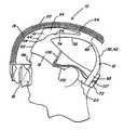
- FIG. 1illustrates a side view of an exemplary embodiment of a mask apparatus in accordance with aspects of the present inventions
- FIG. 2illustrates a top view of an exemplary embodiment of a mask apparatus in accordance with aspects of the present inventions
- FIG. 3illustrates a frontal view of an exemplary embodiment of a mask apparatus in accordance with aspects of the present inventions
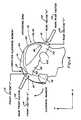
- FIG. 4illustrates exemplary force vectors on an exemplary mask apparatus in accordance with aspects of the present inventions
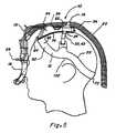
- FIG. 5illustrates a side view of an exemplary embodiment of a mask apparatus with nares seals in accordance with aspects of the present inventions
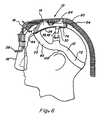
- FIG. 6illustrates a side view of an exemplary embodiment of a mask apparatus with a nasal mask in accordance with aspects of the present inventions
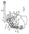
- FIG. 7illustrates a top view of an exemplary embodiment of a mask apparatus in accordance with aspects of the present inventions
- FIG. 8Aillustrates perspective view showing various lower and inner surfaces of at least a portion of a mask apparatus in accordance with aspects of the present inventions
- FIG. 8Billustrates a perspective view showing various upper and outer surfaces of at least a portion of a mask apparatus in accordance with aspects of the present inventions.
- FIG. 9illustrates a side view of another exemplary embodiment of a mask apparatus in accordance with aspects of the present inventions.
- the present inventionsprovide mask apparatus 10 and associated methods for use in conjunction with positive pressure airway therapies.
- the mask apparatus 10include a plurality of stabilizing bands 12 and a mount 14 .
- a mask 16may be secured relative to the mount 14 .
- the mount 14may be secured to the head of a user by one or more bands 12 to secure the mask 16 in communication with airway of the user.
- the bands 12 and mount 14are configured to bias the mask 16 against aspects of the user's face to form a seal between the mask 16 and the face sufficient to permit the administering of a positive pressure therapy to the user.
- the mask 16is cantilevered from the mount 14 and configured to exert a sealing force against the face of a user to eliminate the need for bands extending over the sensitive portions of face below the forehead and eyebrows.
- Airis used to denote a gas to be delivered to a user and includes atmospheric gas, oxygen, other gases or combinations of these gases.
- Crown of the headrefers to the area of the head past the vertical plane of the forehead, that is, the top of the head.
- “Hair line”refers to highest area of the forehead, whether or not hair may be present.
- a mask 16refers to any device for linking a positive pressure system (blower) to the airway of a user in certain embodiments, a mask 16 may cover the full face, the nose and mouth, or only the nose, may seal over or within the nares of the nose or seal in the mouth.
- FIG. 10generally illustrate various embodiments of mask apparatus 10 including aspects of the present inventions.
- the particular exemplary embodiments of the mask apparatus 10 illustrated in the figureshave been chosen for ease of explanation and understanding of various aspects of the present inventions. These illustrated embodiments are not meant to limit the scope of coverage but instead to assist in understanding the context of the language used in this specification and the appended claims. Accordingly, variations of mask apparatus 10 for use in administering positive pressure respiratory therapies different from the illustrated embodiments may be encompassed by the appended claims.
- the mask apparatus 10includes a plurality of support bands 12 and a mount 14 .
- the support bands 12include at least a circumferential band 22 , a first lateral stabilizing band 32 and a second lateral stabilizing band 42 .
- Each band 12may be secured to the mount 14 .
- the circumferential band 22may be configured to extend around the head of a user.
- a portion of the mount 14may be secured to the circumferential band 22 .
- a first lateral stabilizing band 32 and a second lateral stabilizing band 42extend between the circumferential band 22 and the mount 14 .
- the bands 12are generally configured to secure the relative position of the mount 14 on the head of a user.
- One or more of the bands 12may have adjustable lengths to permit the proper fitting of the mask apparatus 10 to a user.
- the bands 12 and the mount 14may be generally configured to secure the mount 14 in a medial position on the head of a user. The position is typically superior to the nose of the user.
- the mask 16 or portions of mask 16may be secured relative to the mount 14 and extend from an anterior edge 64 of the mount 14 .
- the mask 16may be cantilevered from the mount 14 .
- the distance that the mask may be cantilevered from the anterior edge 64 of the mount 14may be adjustable for proper fitment or otherwise.
- the relative angle of the mount 14 and the mask 16may also be adjustable for proper fitting and sealing.
- the cantilevering of the mask 16 from the mount 14may be configured to exert a force in tension or about a fulcrum to properly seal the mask 16 against the user to permit the administration of a positive pressure therapy.
- a support 18may also secure the mask 16 to the mount 14 .
- the support 18may be generally configured to at least in part, confer a force between the mount 14 and/or plurality of bands 12 and the mask 16 .
- a tube 20may be provided to communicate a supply of pressurized air to the mask 16 .
- the tube 20may be secured at one or more locations to the mount 14 .
- the mount 14is generally configured to provide a stable structure to which the mask 16 is mounted.
- the mask 16is cantilevered from the mount 14 .
- the structure of the mount 14may be unitary or composite. Portions of mask 16 may be rigid formed from a rigid or substantially rigid material while other portions are formed from a compliant material as will be recognized by those skilled in the art upon review of the present disclosure. Various stiffening or shaping wires may also be integrated into the mask or secured to the mask as necessary for particular application or fitment of the mask 16 .
- a lower surface 24 of the mount 14may be configured to conform to the shape of a portion of the head of the user.
- An upper surface 34 of the mount 14may be configured to secure a portion of the mask 16 , a support 18 and/or a tube 20 .
- the mount 14defines an anterior edge 64 from which the mask 16 or portions of the mask 16 may extend.
- the mount 14may include a base 74 secured to at least a portion of the lower surface of the mount 14 .
- the base 74may provide a cushion between the mount 14 and the head of a user.
- the base 74may provide a structural member which is connected to or integral with the bands 12 to receive a force exerted by the bands 12 .
- the base 74may function both as a structural member and a cushion.
- the base 74may function as a frictional element.
- the bands 12are typically in the form of elongated members that are configured to exert sufficient tension to retain the mask apparatus 10 on the head of a user and, more particularly, to retain the mask 16 over the airway of a user as the user sleeps.
- the bands 12are configured as flattened straps to comfortably distribute a force over their surface area.
- the bands 16may be formed from one or more stretchable elastic materials, substantially unstretchable material, or other materials as will be recognized by those skilled in the art upon review of the present disclosure.
- the bands 12may be integrally formed or interconnected by a variety of mechanical linkages.
- the bands 12may incorporate various buckles, snaps, hook and loop type fasteners, such as that sold under the trade name Velcro®, or other components to link and/or permit relative adjustment of the bands 12 .
- Various aspects of the bands 12may be adjustable by a user. These aspects may include length, relative positions or other aspects as will be recognized by those skilled in the art upon review of the present disclosure.
- the circumferential band 22is generally configured to extend about at least a portion of the circumference of a user's head.
- the circumferential band 22may be a unitary or a composite member. When configured as a composite member, one or more bands 12 may be linked to form the circumferential band 22 .
- the circumferential band 22may include an anterior portion 62 configured to be positioned on an anterior location of a user's head.
- the circumferential band 22may also include a posterior portion 72 configured to extend about a posterior region of a user's head.
- the posterior portion 72may be configured as a unitary structure.
- the unitary structuremay consist solely of a compliant material. This structure may be devoid of hard components that may create pressure points and discomfort as a user sleeps.
- the mount 14may be secured to the circumferential band 22 at a location on the anterior portion 62 of the circumferential band 22 .
- the circumferential band 22may be continuous about its circumference, may define a first end 82 and a second end 92 , or may be otherwise configured as will be recognized by those skilled in the art upon review of the present disclosure.
- the circumferential band 22defines a first end 82 and a second end 92
- the first end 82 and the second end 92may be secured to one another, secured to aspects of the mount 14 , or may be otherwise configured to secure the circumferential band 22 about at least a portion of the circumference of a user's head.
- the mount 14may be secured to the circumferential band 22 at an anterior portion 62 of the circumferential band 32 .
- An angle 102may be formed between the anterior portion 62 and the posterior portion 72 of the circumferential band.
- the angle 102may be formed as a curve in the circumferential band 22 or in a lower edge of the circumferential band to prevent irritating contact with aspects of the ear of a user.
- the angle 102may be formed to direct the one or more forces exerted by the circumferential band 22 to at least assist in holding the apparatus 10 in place on the head of a user.
- the first lateral stabilizing band 32 and the second lateral stabilizing band 42are generally configured to stabilize the mount 14 on the head of a user.
- the first lateral stabilizing band 32 and the second lateral stabilizing band 42each define at least a first end and a second end.
- the first lateral stabilizing band 32 and the second lateral stabilizing band 42may be integral or may be secured to the circumferential band 22 at their first ends.
- the second ends of each of the first lateral stabilizing band 32 and the second lateral stabilizing band 42may be secured to the mount 14 .
- the second ends of the first lateral stabilizing band 32 and the second lateral stabilizing band 42may be attached toward or at the posterior end 54 of the mount 14 .
- the mask 16is generally configured to communicate pressurized air to the airway of a user.
- the mask 16is secured to the mount 14 .
- the mask 16may be configured as a face mask, a nose mask, a pair of nares seals, a mouthpiece, or otherwise as will be recognized by those skilled in the art upon review of the present disclosure.
- the mask 16generally includes a passage, an air outlet and one or more seals. In certain aspects, the air outlet and the seals may be formed from corresponding structure.
- the passageis defined by the mask 16 and is configured to receive pressurized air from a blower and may be configured to receive a tube 20 or to be received by a tube 20 .
- the air outletis defined by the mask and/or the seal(s) 46 of the mask 16 .
- the air outletis configured to communicate air from the passage to the airway of a user.
- the seal 46 or seals 46are configured to abut a portion of the face of a user to provide a sufficient seal that pressurized air may be provided through the passage and received within the airway of a user from the air outlet of the mask 16 .
- the mask 16is cantilevered from a leading edge 64 of the mount 14 .
- the mask 16may include one or more rigid portions to permit the mask 16 to exert sufficient force against the face or portion thereof of the user to seal the mask 16 against the user to permit the administration of a positive pressure therapy.
- the mask 16may be secured directly to the mount 14 , may be secured to the mount 14 with a support 18 , or may be otherwise secured as will be recognized by those skilled in the art upon review of the present disclosure.
- the mask 16may exert a force about a moment arm extending from the mount 14 , may be held in tension between aspects of the users face and the mount 14 , may exert a combination of such forces, or may otherwise contact a user's face to permit adequate sealing for administration of a positive pressure therapy.
- the tube 20is generally configured to communicate air from a source of pressurized air, such as a blower, to the passage 26 of the mask 16 .
- the tube 20may be in the form of a flexible ribbed hose.
- the tube 20may include various flexible and/or twistable couplers to avoid torque and tension as a user moves during sleep.
- An opening at a first end of the tube 20is generally configured to communicate with the source of pressurized air.
- An opening at the second end of the tube 20is generally configured to communicate pressurized air to the passage 26 of a mask 16 .
- the circumference band 22may extend from the middle of the forehead, avoiding the sensitive eye and eyebrow regions, to below the inion protrusion of the occipital bone (the nape of the neck). In certain aspects, this positioning may provide the desired stability to the mount 14 .
- the circumferential band 22may be connected to the base 74 to secure the circumferential band 22 to the anterior end 44 of the mount 14 .
- the second ends of the first lateral stabilizing band 32 and the second lateral stabilizing band 42are secured to the base 74 toward the posterior end 54 of the mount 14 . Because the bands 12 may be sufficiently clamped, the base 74 may be sufficiently established such that it serves as a stable support for the mount 14 .
- the mask 16 and/or support 18may be capable of creating a counter-clockwise moment, as shown in FIG. 4 , needed to keep the mask 16 biased against the face, which translates the force into a clockwise moment of the mask loading force, tending to keep the mask 16 on the face without leaking.
- the support 18can be configured with one or more arms and may be particularly configured with two arms as illustrated in the Figures for exemplary purposes.
- the arm or arms of the support 18may be mounted to the rigid or semi-rigid mount 14 and configured to position and/or secure the mask 16 over a patient's airway.
- the circumferential band 22may be fitted with adjustment means 106 and quick-sizing cord 107 to assist in fitment of the circumferential band 22 on a user's head.
- the loop 28 of the support 18may fit around the distal surface of the mask 16 .
- An adjustmentmay be provided for one or more of the mount 14 , the mask 16 and the support 18 .
- the adjustmentmay be in the form of a ratchet, a rotating fitting, a threaded fitted or a friction fitting, for example.
- the adjustmentmay permit the relative positioning of the mask 16 and the mount 14 .
- the tube 20may pass through the groove formed by the loop 28 of the support 18 .
- the tube 20may be secured to the support 18 . At least a portion of the tube 20 may also be secured to the mount 14 or the base 74 .
- the forcesmay be distributed between the bands 12 , mount 14 , mask 16 and/or support to bias the mask 16 against aspects of a user's face when worn on the head of a user.
- the forcemay be transmitted from the top of the head to the mask 16 via the support 18 . It should be noted that the force will vary from user to user.
- the variablesmay include:
- the biasing forcemay be increased or decreased by shortening or lengthening each arm of the support 18 .
- the loading of the circumferential band 22may be applied independently of the loading for the mask 16 .
- the vectors created in tightening the bands 12include the main rear vector 112 and the main front vector 113 , which each occur normal to the surface of the head.
- the analysis of the resultant vectors X 114 and Y 115show how the “clamping” of the head may be accomplished.
- the extensive stability of the anchoring zone established by the mount 14 and/or base 74may allow for the use of a short length of rigid or semi-rigid material comprising the mount 14 . It should be noted that the mount 14 and the support 18 may be configured as the only components of the mask apparatus 10 that are not soft and flexible.
- the support 18may be configured to create a counter-clockwise moment, as shown in FIG. 4 for exemplary purposes, that may keep the mask 16 biased against the face. This may translate the force into a clockwise moment of the mask loading force, tending to keep the mask 16 on the face without leaking and without the loading force being applied to a small anchor area.
- the usermay adjust the bands 12 using the adjustment mechanism 106 to a “loose comfort” and place the cap on his or her head, positioning it from the nape of the neck to the forehead.
- the userthen uses the quick-sizing cord 107 (on those embodiments which are provided with a quick-sizing means) to pull the bands 12 snugly around the head.
- the bands 12may be adjusted for proper fitting.
- the tube 20 from a blowermay be attached to a face mask 16 so that the loop 28 of the support 18 passes around the distal protuberance of the mask 16 .
- the ends of the support 18may be fitted into one or more slots in the mount 14 and the length adjusted to accommodate variations in bias force required to hold the mask 16 biased against the patient's face.
- the support 18may be left attached to the mount 14 .
- FIGS. 5 to 7show exemplary embodiments of a mask apparatus 10 .
- the illustrated embodimentsinclude a circumferential band 22 encircling the head from the forehead just below the hair line to the inion protrusion of the occipital bone of a user for exemplary purposes.
- the circumferential band 22 in this embodimentmay be configured to sit higher on the head of the user than in the embodiment of FIGS. 1 to 4 . Therefore, an angle 102 , in the form of an S-shaped curve, at approximately the level of the ear may prevent contact with the aspects of the ears.
- the lateral stabilizing band 32 , 42extends upward from approximately the area of the angle 102 to the crown of the head for exemplary purposes.
- the mount 14may be positioned to extend between about the circumferential band 22 and the lateral stabilizing bands 32 , 42 .
- the mount 14may rest on a base 74 .
- the mount 14may be attached to the lateral stabilizing bands 32 , 42 through an attachment 30 on each side of the mount 14 .
- the mount 14may be provided with receiving slots 27 A and 27 B to secure the support 18 to the mount 14 .
- Additional receiving slots 27 C and 27 Dmay also be provide in mount 14 to secure particular configurations of supports 18 .
- Tube 20extends along the top surface of the mount 14 and thence down along the support 18 to loop 28 around the plenum and/or the nasal mask 16 .
- the plenum 56may function to receive and vent air.
- the plenum 56may be positioned at or about the loop 28 of the support 18 .
- the loop 28may pass around the plenum 56 , rather than around the entire mask 16 . This may afford sufficient biasing force because the preferred nasal mask may be lightly anchored in the nares of the user and may be light in weight.
- FIGS. 8A and 8Billustrate an exemplary embodiment of bands 12 and portions thereof that are molded into a unitary component which is secure to the mount 14 .
- the mount 14is secured over aspects of the circumferential band 22 and a base 74 .
- the ends of the circumferential band 22may be attached securely to each other by sonic welding, adhesives, or other fixed bonding method, but preferably are attached using adjustable mechanisms, such as for example, buckles, snaps, or hook and loop type fasteners.
- Portions of the lateral stabilizing bands 32 , 42are shown molded as tongues of the circumferential band 22 .
- the attachmentsmay be formed on the mount 14 or on the outer substrate of the lateral stabilizing band 32 , 42 .
- Both the circumferential band 22 and the lateral stabilizing bands 32 , 42may be formed of an outer substrate that may be sufficiently firm to prevent the bands 12 from rolling, with an inner substrate of softer material on the side that contacts the skin and/or hair. An elastic and/or cushioning material may be provided between the inner substrate and the outer substrate.
- the bands 12may be formed of any suitable materials or combinations of materials, such as for example, silicone/silicone foam or polyethylene/polyethylene foam.
- FIG. 9illustrates another exemplary embodiment of a mask apparatus 10 .
- the illustrated embodimentincludes a circumferential band 22 encircling the head from the forehead to approximately the inion protrusion of the occipital bone of a user for exemplary purposes.
- the lateral stabilizing bands 32 , 42are a single band extending circumferentially about the head.
- the lateral stabilizing bands 32 , 42extend from the top of the head to a location superior the circumferential band 22 on the occipital bone of a user for exemplary purposes.
- the lateral stabilizing bands 32 , 42may be secured to the circumferential band at a posterior portion of the circumferential band 22 .
- the lateral stabilizing bands 32 , 42may be unsecured to the circumferential band and independently positionable about the head.
- the circumferential band 22may be secured at or toward an anterior end 44 of the mount 14 .
- the lateral stabilizing bands 32 , 42may be secured at or toward the posterior end 54 of the mount 14 .
- the mount 14may rest on a base 74 . In certain aspects the mount 14 is secured to the base 74 .
- the mount 14may be attached to the circumferential band 22 and lateral stabilizing bands 32 , 42 through attachments 30 .
- the attachments 30may include slots to receive the circumferential band 22 and lateral stabilizing bands 32 , 42 through.
- the attachments 30may be positioned on opposing sides of the mount 14 .
- the mount 14may be provided with receiving slots 27 A and 27 B to secure the support 18 to the mount 14 . Additional receiving slots 27 C and 27 D may also be provide in mount 14 to secure particular configurations of supports 18 .
- the tube 20may be in fluid communication with a passage within a support 18 .
- the mask 16is also in fluid communication with the passage of support 18 to communicate air to a user.
- the support 18cantilevers the mask from the anterior edge 64 of the mount 14 .
- the illustrated exemplary embodiment of a mask apparatus 10 in accordance with aspects of the present inventionsmay provide the force necessary to hold the mask 16 biased against the face.
- the forcesmay be transmitted from the top of the head and/or forehead to the nasal area or face via the mask 16 and/or support 18 . It should be noted that the force will vary from user to user.
- the variablesinclude:
- a usersecures positions the circumferential band 22 about the user's head.
- the userpositions the mask 16 in communication with the user's airways.
- the useradjusts the circumferential band 22 , the first lateral stabilizing band 32 and the second lateral stabilizing band 42 to permit adequate sealing of the mask 16 for the administration of a positive airway pressure therapy.
- the tube 20is placed in communication with a blower configured to deliver pressurized air for positive airway pressure therapies. The positive airway pressure therapy may then be administered to the user.
Landscapes
- Health & Medical Sciences (AREA)
- Pulmonology (AREA)
- Heart & Thoracic Surgery (AREA)
- Engineering & Computer Science (AREA)
- Anesthesiology (AREA)
- Biomedical Technology (AREA)
- Emergency Medicine (AREA)
- Hematology (AREA)
- Life Sciences & Earth Sciences (AREA)
- Animal Behavior & Ethology (AREA)
- General Health & Medical Sciences (AREA)
- Public Health (AREA)
- Veterinary Medicine (AREA)
- Otolaryngology (AREA)
- Orthopedics, Nursing, And Contraception (AREA)
Abstract
Description
Claims (4)
Priority Applications (1)
| Application Number | Priority Date | Filing Date | Title |
|---|---|---|---|
| US11/805,161US7845353B2 (en) | 2002-08-20 | 2007-05-21 | Face mask support |
Applications Claiming Priority (6)
| Application Number | Priority Date | Filing Date | Title |
|---|---|---|---|
| US40468502P | 2002-08-20 | 2002-08-20 | |
| US10/643,642US6854465B2 (en) | 2002-08-20 | 2003-08-19 | Face mask support |
| US61953904P | 2004-10-15 | 2004-10-15 | |
| US11/056,858US7089941B2 (en) | 2002-08-20 | 2005-02-12 | Face mask support |
| US11/455,544US8091553B2 (en) | 2002-08-20 | 2006-06-19 | Face mask support |
| US11/805,161US7845353B2 (en) | 2002-08-20 | 2007-05-21 | Face mask support |
Related Parent Applications (1)
| Application Number | Title | Priority Date | Filing Date |
|---|---|---|---|
| US11/455,544Continuation-In-PartUS8091553B2 (en) | 2002-08-20 | 2006-06-19 | Face mask support |
Publications (2)
| Publication Number | Publication Date |
|---|---|
| US20080053451A1 US20080053451A1 (en) | 2008-03-06 |
| US7845353B2true US7845353B2 (en) | 2010-12-07 |
Family
ID=39149805
Family Applications (1)
| Application Number | Title | Priority Date | Filing Date |
|---|---|---|---|
| US11/805,161Expired - Fee RelatedUS7845353B2 (en) | 2002-08-20 | 2007-05-21 | Face mask support |
Country Status (1)
| Country | Link |
|---|---|
| US (1) | US7845353B2 (en) |
Cited By (7)
| Publication number | Priority date | Publication date | Assignee | Title |
|---|---|---|---|---|
| US20060231102A1 (en)* | 2002-08-20 | 2006-10-19 | Bordewick Steven S | Face mask support |
| US20080006275A1 (en)* | 2006-07-07 | 2008-01-10 | Steven Nickelson | Composite masks and methods for positive airway pressure therapies |
| US8602025B2 (en) | 2006-04-10 | 2013-12-10 | Somnetics Global Pte. Ltd. | Apparatus and methods for providing humidity in respiratory therapy |
| US8631791B2 (en) | 2006-04-10 | 2014-01-21 | Somnetics Global Pte. Ltd. | Apparatus and methods for administration of positive airway pressure therapies |
| US10369316B2 (en) | 2011-10-04 | 2019-08-06 | Koninklijke Philips N.V. | Forhead gas supply assembly for a patient interface system |
| US20230233790A1 (en)* | 2018-06-22 | 2023-07-27 | Koninklijke Philips N.V. | Patient interface stabilization device |
| US11724050B2 (en) | 2013-12-17 | 2023-08-15 | Somnetics International, Inc. | Humidification system and positive airway pressure apparatus incorporating same |
Families Citing this family (15)
| Publication number | Priority date | Publication date | Assignee | Title |
|---|---|---|---|---|
| US7845353B2 (en) | 2002-08-20 | 2010-12-07 | Aeiomed, Inc. | Face mask support |
| WO2007149446A2 (en)* | 2006-06-16 | 2007-12-27 | Aeiomed, Inc. | Modular positive airway pressure therapy apparatus and methods |
| US9782553B2 (en)* | 2007-07-13 | 2017-10-10 | Resmed Limited | Patient interface and non-invasive positive pressure ventilating method |
| US20090078258A1 (en)* | 2007-09-21 | 2009-03-26 | Bowman Bruce R | Pressure regulation methods for positive pressure respiratory therapy |
| US20090078255A1 (en)* | 2007-09-21 | 2009-03-26 | Bowman Bruce R | Methods for pressure regulation in positive pressure respiratory therapy |
| WO2010080709A1 (en) | 2009-01-08 | 2010-07-15 | Hancock Medical | Self-contained, intermittent positive airway pressure systems and methods for treating sleep apnea, snoring, and other respiratory disorders |
| DE102009016150A1 (en) | 2009-04-04 | 2010-10-07 | F. Stephan Gmbh | Atraumatic nasal tube for noninvasive respiratory support (NIV-CPAP) |
| JP6108471B2 (en)* | 2010-12-13 | 2017-04-05 | コーニンクレッカ フィリップス エヌ ヴェKoninklijke Philips N.V. | Headgear strap member with improved comfort |
| US8327846B2 (en) | 2011-02-08 | 2012-12-11 | Hancock Medical, Inc. | Positive airway pressure system with head position control |
| WO2014117179A1 (en) | 2013-01-28 | 2014-07-31 | Hancock Medical, Inc. | Position control devices and methods for use with positive airway pressure systems |
| WO2016028525A1 (en) | 2014-08-18 | 2016-02-25 | Hancock Medical, Inc. | Portable pap device with humidification |
| USD776802S1 (en) | 2015-03-06 | 2017-01-17 | Hancock Medical, Inc. | Positive airway pressure system console |
| WO2017124152A1 (en) | 2016-01-21 | 2017-07-27 | Resmed Limited | Adjustable headgear tubing for a patient interface |
| EP3457926A4 (en) | 2016-05-19 | 2020-09-09 | Hancock Medical, Inc. | SYSTEM FOR DETECTING POSITIONAL OBSTRUCTIVE SLEEP APNEA |
| AU2019323224B2 (en) | 2018-08-20 | 2021-10-21 | ResMed Pty Ltd | Headgear for a patient interface |
Citations (50)
| Publication number | Priority date | Publication date | Assignee | Title |
|---|---|---|---|---|
| US1081745A (en) | 1912-05-03 | 1913-12-16 | White S Dental Mfg Co | Nasal inhaler. |
| US1282527A (en) | 1918-04-13 | 1918-10-22 | Gratien Bidonde | Life-preserver. |
| US1632449A (en) | 1924-07-17 | 1927-06-14 | Elmer I Mckessson | Mask |
| US2241535A (en) | 1939-07-28 | 1941-05-13 | Walter M Boothby | Apparatus for delivering and permitting normal breathing of mixtures of gases |
| US2965902A (en) | 1958-03-07 | 1960-12-27 | Delbert G Louch | Head protector |
| US3599635A (en) | 1969-03-12 | 1971-08-17 | Sierra Eng Co | Hanging quick donning mask suspension |
| US3721233A (en) | 1970-10-30 | 1973-03-20 | W Montgomery | T-shaped tracheal stent |
| US3799164A (en) | 1971-08-12 | 1974-03-26 | Du Pont | Analgesic apparatus |
| US4151843A (en) | 1976-06-28 | 1979-05-01 | Brekke John H | Apparatus for administration of a gas to a human and the exhausting thereof |
| US4593688A (en) | 1984-05-30 | 1986-06-10 | Payton Hugh W | Apparatus for the delivery of oxygen or the like |
| US4644947A (en) | 1982-04-15 | 1987-02-24 | Whitwam James G | Respirator |
| US4944310A (en) | 1981-04-24 | 1990-07-31 | Somed Pty. Ltd. | Device for treating snoring sickness |
| US5054484A (en) | 1990-11-21 | 1991-10-08 | Hebeler Jr Robert F | Tracheostomy device |
| US5421799A (en) | 1994-08-01 | 1995-06-06 | Rabin; Gustavo R. | Scalp massager |
| US5538000A (en) | 1995-02-06 | 1996-07-23 | Hans Rudolph, Inc. | Airflow delivery system |
| US5542128A (en) | 1993-04-20 | 1996-08-06 | Lomas; Christiane | Headwear for supporting a breathing apparatus |
| US5623923A (en) | 1993-06-09 | 1997-04-29 | Intertechnique | Respiratory equipment with comfort adjustment |
| US5662101A (en)* | 1995-12-07 | 1997-09-02 | Respironics, Inc. | Respiratory facial mask |
| US5687715A (en) | 1991-10-29 | 1997-11-18 | Airways Ltd Inc | Nasal positive airway pressure apparatus and method |
| US5724965A (en) | 1995-06-06 | 1998-03-10 | Respironics Inc. | Nasal mask |
| US5954050A (en) | 1997-10-20 | 1999-09-21 | Christopher; Kent L. | System for monitoring and treating sleep disorders using a transtracheal catheter |
| US6119693A (en) | 1998-01-16 | 2000-09-19 | Resmed Limited | Forehead support for facial mask |
| US20020011248A1 (en) | 1999-11-09 | 2002-01-31 | Gary L. Hansen | Cantilever device and method for breathing devices and the like |
| US6494207B1 (en) | 1996-12-02 | 2002-12-17 | Resmed Limited | Harness assembly for a nasal mask |
| US6505623B1 (en) | 1999-06-04 | 2003-01-14 | Mallinckrodt Inc. | Hat-held respiratory mask |
| US6516802B2 (en) | 1999-03-26 | 2003-02-11 | Mallinckrodt, Inc. | Method and combination for treating sleep apnea using a cantilever mask attachment device |
| US6530373B1 (en) | 2000-08-04 | 2003-03-11 | Mallinckrodt Inc. | Respirator mask |
| US6532960B1 (en) | 2000-07-10 | 2003-03-18 | Respironics, Inc. | Automatic rise time adjustment for bi-level pressure support system |
| US20030051732A1 (en) | 2001-08-20 | 2003-03-20 | Smith Nicholas Charles Alan | Headgear for nasal masks |
| US6536435B1 (en) | 1999-02-22 | 2003-03-25 | Cabot Safety Intermediate Corporation | Respirator headpiece and release mechanism |
| US20030172936A1 (en) | 2000-06-19 | 2003-09-18 | Paul Wilkie | Mask |
| US20040025882A1 (en) | 2000-07-21 | 2004-02-12 | Stefan Madaus | Holding device for a respiratory mask |
| WO2004012803A1 (en) | 2002-08-05 | 2004-02-12 | Resmed Limited | Inextensible headgear and cpap or ventilator mask assembly with same |
| US6694978B1 (en) | 1999-12-02 | 2004-02-24 | Siemens-Elema Ab | High-frequency oscillation patient ventillator system |
| US20040035427A1 (en) | 2002-08-20 | 2004-02-26 | Bordewick Steven S. | Face mask support |
| US6789543B2 (en) | 2002-07-02 | 2004-09-14 | James L. Cannon | Assisted breathing device and method of wearing same |
| US20040226566A1 (en) | 2003-02-21 | 2004-11-18 | Resmed Limited | Nasal assembly |
| US20040226562A1 (en) | 2002-12-06 | 2004-11-18 | Bordewick Steven S. | Blower assembly for CPAP |
| US6886564B2 (en) | 2000-07-17 | 2005-05-03 | Australian Centre For Advanced Medical Technology Ltd. | Nasal mask with integral mouldable straps |
| US20050150499A1 (en) | 2002-08-20 | 2005-07-14 | Bordewick Steven S. | Face mask support |
| US20060231097A1 (en) | 2005-04-02 | 2006-10-19 | Dougherty Timothy R | Apparatus for CPAP therapy |
| US7156090B2 (en) | 2002-01-21 | 2007-01-02 | Hiroaki Nomori | Tracheostomy tube |
| US20070277825A1 (en) | 2006-04-10 | 2007-12-06 | Bordewick Steven S | Apparatus and methods for providing humidity in respiratory therapy |
| US20070277827A1 (en) | 2006-04-10 | 2007-12-06 | Bordewick Steven S | Apparatus and methods for administration of positive airway pressure therapies |
| US20080006275A1 (en) | 2006-07-07 | 2008-01-10 | Steven Nickelson | Composite masks and methods for positive airway pressure therapies |
| US20080053451A1 (en) | 2002-08-20 | 2008-03-06 | Bordewick Steven S | Face mask support |
| EP1334742B1 (en) | 2001-09-07 | 2008-04-02 | ResMed Ltd. | Mask assembly |
| US7357136B2 (en) | 2003-08-18 | 2008-04-15 | Ric Investments, Llc | Patient interface assembly and system using same |
| US7487778B2 (en) | 2003-08-11 | 2009-02-10 | Breathe Technologies, Inc. | Tracheal catheter and prosthesis and method of respiratory support of a patient |
| US7588033B2 (en) | 2003-06-18 | 2009-09-15 | Breathe Technologies, Inc. | Methods, systems and devices for improving ventilation in a lung area |
- 2007
- 2007-05-21USUS11/805,161patent/US7845353B2/ennot_activeExpired - Fee Related
Patent Citations (55)
| Publication number | Priority date | Publication date | Assignee | Title |
|---|---|---|---|---|
| US1081745A (en) | 1912-05-03 | 1913-12-16 | White S Dental Mfg Co | Nasal inhaler. |
| US1282527A (en) | 1918-04-13 | 1918-10-22 | Gratien Bidonde | Life-preserver. |
| US1632449A (en) | 1924-07-17 | 1927-06-14 | Elmer I Mckessson | Mask |
| US2241535A (en) | 1939-07-28 | 1941-05-13 | Walter M Boothby | Apparatus for delivering and permitting normal breathing of mixtures of gases |
| US2965902A (en) | 1958-03-07 | 1960-12-27 | Delbert G Louch | Head protector |
| US3599635A (en) | 1969-03-12 | 1971-08-17 | Sierra Eng Co | Hanging quick donning mask suspension |
| US3721233A (en) | 1970-10-30 | 1973-03-20 | W Montgomery | T-shaped tracheal stent |
| US3799164A (en) | 1971-08-12 | 1974-03-26 | Du Pont | Analgesic apparatus |
| US4151843A (en) | 1976-06-28 | 1979-05-01 | Brekke John H | Apparatus for administration of a gas to a human and the exhausting thereof |
| US4944310A (en) | 1981-04-24 | 1990-07-31 | Somed Pty. Ltd. | Device for treating snoring sickness |
| US4644947A (en) | 1982-04-15 | 1987-02-24 | Whitwam James G | Respirator |
| US4593688A (en) | 1984-05-30 | 1986-06-10 | Payton Hugh W | Apparatus for the delivery of oxygen or the like |
| US5054484A (en) | 1990-11-21 | 1991-10-08 | Hebeler Jr Robert F | Tracheostomy device |
| US5687715A (en) | 1991-10-29 | 1997-11-18 | Airways Ltd Inc | Nasal positive airway pressure apparatus and method |
| US5542128A (en) | 1993-04-20 | 1996-08-06 | Lomas; Christiane | Headwear for supporting a breathing apparatus |
| US5623923A (en) | 1993-06-09 | 1997-04-29 | Intertechnique | Respiratory equipment with comfort adjustment |
| US5421799A (en) | 1994-08-01 | 1995-06-06 | Rabin; Gustavo R. | Scalp massager |
| US5538000A (en) | 1995-02-06 | 1996-07-23 | Hans Rudolph, Inc. | Airflow delivery system |
| US5724965A (en) | 1995-06-06 | 1998-03-10 | Respironics Inc. | Nasal mask |
| US5662101A (en)* | 1995-12-07 | 1997-09-02 | Respironics, Inc. | Respiratory facial mask |
| US6494207B1 (en) | 1996-12-02 | 2002-12-17 | Resmed Limited | Harness assembly for a nasal mask |
| US5954050A (en) | 1997-10-20 | 1999-09-21 | Christopher; Kent L. | System for monitoring and treating sleep disorders using a transtracheal catheter |
| US6119693A (en) | 1998-01-16 | 2000-09-19 | Resmed Limited | Forehead support for facial mask |
| US6536435B1 (en) | 1999-02-22 | 2003-03-25 | Cabot Safety Intermediate Corporation | Respirator headpiece and release mechanism |
| US6516802B2 (en) | 1999-03-26 | 2003-02-11 | Mallinckrodt, Inc. | Method and combination for treating sleep apnea using a cantilever mask attachment device |
| US6505623B1 (en) | 1999-06-04 | 2003-01-14 | Mallinckrodt Inc. | Hat-held respiratory mask |
| US20020011248A1 (en) | 1999-11-09 | 2002-01-31 | Gary L. Hansen | Cantilever device and method for breathing devices and the like |
| US6347631B1 (en) | 1999-11-09 | 2002-02-19 | Mallinckrodt, Inc. | Cantilever device and method for breathing devices and the like |
| US6694978B1 (en) | 1999-12-02 | 2004-02-24 | Siemens-Elema Ab | High-frequency oscillation patient ventillator system |
| US20030172936A1 (en) | 2000-06-19 | 2003-09-18 | Paul Wilkie | Mask |
| US6532960B1 (en) | 2000-07-10 | 2003-03-18 | Respironics, Inc. | Automatic rise time adjustment for bi-level pressure support system |
| US6886564B2 (en) | 2000-07-17 | 2005-05-03 | Australian Centre For Advanced Medical Technology Ltd. | Nasal mask with integral mouldable straps |
| US20040025882A1 (en) | 2000-07-21 | 2004-02-12 | Stefan Madaus | Holding device for a respiratory mask |
| US6530373B1 (en) | 2000-08-04 | 2003-03-11 | Mallinckrodt Inc. | Respirator mask |
| US20030051732A1 (en) | 2001-08-20 | 2003-03-20 | Smith Nicholas Charles Alan | Headgear for nasal masks |
| EP1334742B1 (en) | 2001-09-07 | 2008-04-02 | ResMed Ltd. | Mask assembly |
| US7156090B2 (en) | 2002-01-21 | 2007-01-02 | Hiroaki Nomori | Tracheostomy tube |
| US6789543B2 (en) | 2002-07-02 | 2004-09-14 | James L. Cannon | Assisted breathing device and method of wearing same |
| WO2004012803A1 (en) | 2002-08-05 | 2004-02-12 | Resmed Limited | Inextensible headgear and cpap or ventilator mask assembly with same |
| US20040035427A1 (en) | 2002-08-20 | 2004-02-26 | Bordewick Steven S. | Face mask support |
| US20050150499A1 (en) | 2002-08-20 | 2005-07-14 | Bordewick Steven S. | Face mask support |
| US7089941B2 (en) | 2002-08-20 | 2006-08-15 | Bordewick Steven S | Face mask support |
| US20060231102A1 (en) | 2002-08-20 | 2006-10-19 | Bordewick Steven S | Face mask support |
| US20080053451A1 (en) | 2002-08-20 | 2008-03-06 | Bordewick Steven S | Face mask support |
| US6854465B2 (en) | 2002-08-20 | 2005-02-15 | Aeiomed, Inc. | Face mask support |
| US20040226562A1 (en) | 2002-12-06 | 2004-11-18 | Bordewick Steven S. | Blower assembly for CPAP |
| US20040226566A1 (en) | 2003-02-21 | 2004-11-18 | Resmed Limited | Nasal assembly |
| US7588033B2 (en) | 2003-06-18 | 2009-09-15 | Breathe Technologies, Inc. | Methods, systems and devices for improving ventilation in a lung area |
| US7487778B2 (en) | 2003-08-11 | 2009-02-10 | Breathe Technologies, Inc. | Tracheal catheter and prosthesis and method of respiratory support of a patient |
| US7357136B2 (en) | 2003-08-18 | 2008-04-15 | Ric Investments, Llc | Patient interface assembly and system using same |
| WO2006044120A2 (en) | 2004-10-15 | 2006-04-27 | Aeiomed, Inc. | Face mask support |
| US20060231097A1 (en) | 2005-04-02 | 2006-10-19 | Dougherty Timothy R | Apparatus for CPAP therapy |
| US20070277827A1 (en) | 2006-04-10 | 2007-12-06 | Bordewick Steven S | Apparatus and methods for administration of positive airway pressure therapies |
| US20070277825A1 (en) | 2006-04-10 | 2007-12-06 | Bordewick Steven S | Apparatus and methods for providing humidity in respiratory therapy |
| US20080006275A1 (en) | 2006-07-07 | 2008-01-10 | Steven Nickelson | Composite masks and methods for positive airway pressure therapies |
Cited By (10)
| Publication number | Priority date | Publication date | Assignee | Title |
|---|---|---|---|---|
| US20060231102A1 (en)* | 2002-08-20 | 2006-10-19 | Bordewick Steven S | Face mask support |
| US8091553B2 (en) | 2002-08-20 | 2012-01-10 | Somnetics Global Pte. Ltd. | Face mask support |
| US8602025B2 (en) | 2006-04-10 | 2013-12-10 | Somnetics Global Pte. Ltd. | Apparatus and methods for providing humidity in respiratory therapy |
| US8631791B2 (en) | 2006-04-10 | 2014-01-21 | Somnetics Global Pte. Ltd. | Apparatus and methods for administration of positive airway pressure therapies |
| US9597477B2 (en) | 2006-04-10 | 2017-03-21 | Somnetics Global Pte. Ltd. | Apparatus and methods for providing humidity in respiratory therapy |
| US9694153B2 (en) | 2006-04-10 | 2017-07-04 | Somnetics Global Pte. Ltd. | Apparatus and methods for administration of positive airway pressure therapies |
| US20080006275A1 (en)* | 2006-07-07 | 2008-01-10 | Steven Nickelson | Composite masks and methods for positive airway pressure therapies |
| US10369316B2 (en) | 2011-10-04 | 2019-08-06 | Koninklijke Philips N.V. | Forhead gas supply assembly for a patient interface system |
| US11724050B2 (en) | 2013-12-17 | 2023-08-15 | Somnetics International, Inc. | Humidification system and positive airway pressure apparatus incorporating same |
| US20230233790A1 (en)* | 2018-06-22 | 2023-07-27 | Koninklijke Philips N.V. | Patient interface stabilization device |
Also Published As
| Publication number | Publication date |
|---|---|
| US20080053451A1 (en) | 2008-03-06 |
Similar Documents
| Publication | Publication Date | Title |
|---|---|---|
| US7845353B2 (en) | Face mask support | |
| US8091553B2 (en) | Face mask support | |
| US6854465B2 (en) | Face mask support | |
| US12064560B2 (en) | Nasal interfaces for respiratory therapy | |
| US6805117B1 (en) | Universal fitting headgear | |
| US5752510A (en) | Nasal and oral air passageway delivery management apparatus | |
| US7779832B1 (en) | Headgear for use with a patient interface device | |
| AU2005213358B2 (en) | Patient interface assembly supported under the mandible | |
| JP4604133B2 (en) | Respirator wearing device and breathing mask | |
| JP5329421B2 (en) | Patient interface with variable footprint | |
| US20060081252A1 (en) | Headgear | |
| JP2013523203A (en) | Patient interface device with floating adjustment arm | |
| JP2024533790A (en) | Gas exhaust assembly, frame assembly, liner assembly and patient interface device | |
| WO2011107909A1 (en) | Helmet-type of patient interface device and method use | |
| CN101142000A (en) | mask support | |
| US20080149106A1 (en) | Harness system for a breathing mask and method of using same |
Legal Events
| Date | Code | Title | Description |
|---|---|---|---|
| AS | Assignment | Owner name:AEIOMED, INC., MINNESOTA Free format text:ASSIGNMENT OF ASSIGNORS INTEREST;ASSIGNORS:BORDEWICK, STEVEN S.;BOWMAN, BRUCE R.;MARKOVICH, DAVID;AND OTHERS;REEL/FRAME:020089/0757;SIGNING DATES FROM 20070827 TO 20071004 Owner name:AEIOMED, INC., MINNESOTA Free format text:ASSIGNMENT OF ASSIGNORS INTEREST;ASSIGNORS:BORDEWICK, STEVEN S.;BOWMAN, BRUCE R.;MARKOVICH, DAVID;AND OTHERS;SIGNING DATES FROM 20070827 TO 20071004;REEL/FRAME:020089/0757 | |
| FEPP | Fee payment procedure | Free format text:PAYOR NUMBER ASSIGNED (ORIGINAL EVENT CODE: ASPN); ENTITY STATUS OF PATENT OWNER: SMALL ENTITY | |
| STCF | Information on status: patent grant | Free format text:PATENTED CASE | |
| AS | Assignment | Owner name:SOMNETICS GLOBAL PTE. LTD., SINGAPORE Free format text:ASSIGNMENT OF ASSIGNORS INTEREST;ASSIGNOR:AEIOMED, INC.;REEL/FRAME:025809/0759 Effective date:20101207 | |
| FPAY | Fee payment | Year of fee payment:4 | |
| AS | Assignment | Owner name:ASCEND VENTURES LIMITED, VIRGIN ISLANDS, BRITISH Free format text:SECURITY INTEREST;ASSIGNOR:SOMNETICS GLOBAL PTE. LTD.;REEL/FRAME:040168/0001 Effective date:20160825 | |
| AS | Assignment | Owner name:SOMNETICS GLOBAL PTE. LTD., SINGAPORE Free format text:RELEASE BY SECURED PARTY;ASSIGNOR:ASCEND VENTURES LIMITED;REEL/FRAME:045576/0975 Effective date:20180406 | |
| AS | Assignment | Owner name:SOMNETICS INTERNATIONAL, INC., MINNESOTA Free format text:ASSIGNMENT OF ASSIGNORS INTEREST;ASSIGNOR:SOMNETICS GLOBAL PTE. LTD.;REEL/FRAME:045584/0465 Effective date:20180326 | |
| AS | Assignment | Owner name:SOMNETICS INTERNATIONAL, INC., MINNESOTA Free format text:ASSIGNMENT OF ASSIGNORS INTEREST;ASSIGNOR:SOMNETICS GLOBAL PTE. LTD.;REEL/FRAME:045632/0186 Effective date:20180424 | |
| AS | Assignment | Owner name:WHITECLIFF/SOMNETICS L.P., MINNESOTA Free format text:SECURITY INTEREST;ASSIGNOR:SOMNETICS INTERNATIONAL, INC.;REEL/FRAME:045645/0427 Effective date:20180419 | |
| MAFP | Maintenance fee payment | Free format text:PAYMENT OF MAINTENANCE FEE, 8TH YR, SMALL ENTITY (ORIGINAL EVENT CODE: M2552) Year of fee payment:8 | |
| AS | Assignment | Owner name:WHITECLIFF INVESTMENT LLC XXXVI, MINNESOTA Free format text:SECURITY INTEREST;ASSIGNOR:SOMNETICS INTERNATIONAL, INC.;REEL/FRAME:053731/0659 Effective date:20200325 | |
| FEPP | Fee payment procedure | Free format text:MAINTENANCE FEE REMINDER MAILED (ORIGINAL EVENT CODE: REM.); ENTITY STATUS OF PATENT OWNER: SMALL ENTITY | |
| LAPS | Lapse for failure to pay maintenance fees | Free format text:PATENT EXPIRED FOR FAILURE TO PAY MAINTENANCE FEES (ORIGINAL EVENT CODE: EXP.); ENTITY STATUS OF PATENT OWNER: SMALL ENTITY | |
| STCH | Information on status: patent discontinuation | Free format text:PATENT EXPIRED DUE TO NONPAYMENT OF MAINTENANCE FEES UNDER 37 CFR 1.362 | |
| FP | Lapsed due to failure to pay maintenance fee | Effective date:20221207 |