US7845309B2 - Ultra high speed uniform plasma processing system - Google Patents
Ultra high speed uniform plasma processing systemDownload PDFInfo
- Publication number
- US7845309B2 US7845309B2US10/710,457US71045704AUS7845309B2US 7845309 B2US7845309 B2US 7845309B2US 71045704 AUS71045704 AUS 71045704AUS 7845309 B2US7845309 B2US 7845309B2
- Authority
- US
- United States
- Prior art keywords
- electrode
- processing region
- process gas
- plasma
- separating member
- Prior art date
- Legal status (The legal status is an assumption and is not a legal conclusion. Google has not performed a legal analysis and makes no representation as to the accuracy of the status listed.)
- Expired - Fee Related, expires
Links
Images


Classifications
- H—ELECTRICITY
- H01—ELECTRIC ELEMENTS
- H01J—ELECTRIC DISCHARGE TUBES OR DISCHARGE LAMPS
- H01J37/00—Discharge tubes with provision for introducing objects or material to be exposed to the discharge, e.g. for the purpose of examination or processing thereof
- H01J37/32—Gas-filled discharge tubes
- H01J37/32431—Constructional details of the reactor
- H01J37/32798—Further details of plasma apparatus not provided for in groups H01J37/3244 - H01J37/32788; special provisions for cleaning or maintenance of the apparatus
- H01J37/32816—Pressure
- H01J37/32834—Exhausting
- H—ELECTRICITY
- H01—ELECTRIC ELEMENTS
- H01J—ELECTRIC DISCHARGE TUBES OR DISCHARGE LAMPS
- H01J37/00—Discharge tubes with provision for introducing objects or material to be exposed to the discharge, e.g. for the purpose of examination or processing thereof
- H01J37/32—Gas-filled discharge tubes
- H01J37/32431—Constructional details of the reactor
- H01J37/32623—Mechanical discharge control means
- H01J37/32633—Baffles
Definitions
- the inventiongenerally relates to processing apparatus for processing substrates with a plasma.
- Plasma processing systemsare commonly used for modifying the surface properties of substrates in various industrial applications. For example, plasma processing systems are routinely used to plasma treat the surfaces of integrated circuits, electronic packages, and printed circuit boards in semiconductor applications, solar panels, hydrogen fuel cell components, automotive components, and rectangular glass substrates used in flat panel displays. Plasma processing systems are also used in medical applications to modify the surface properties of devices, such as stents and implants, inserted into the human body. Plasma processing systems that rely on conventional parallel-plate type electrodes may experience process non-uniformities across the surface of relatively large substrates positioned in a processing region defined between the electrodes for processing.
- equipotential field linesare induced across the surface of the substrate.
- positive ions from the plasma in the processing regionaccelerate across the equipotential field lines to impinge on the surface of the substrate.
- the plasmais typically distributed over the entire evacuated volume of a processing chamber enclosing the electrodes with the highest plasma density observed between the electrodes.
- the uniformity of the plasma density in the processing region between the electrodesis influenced by external field effects factors, such as grounded chamber sidewalls, that alter the equipotential electric field lines between the electrodes and thereby modify the distribution of the constituent charged components of the plasma.
- the non-uniformitymay be particularly significant at the peripheral edges of the processing region.
- One conventional method of reducing external field effectsis to make the processing chamber larger so that the grounded sidewalls are more distant from the electrodes.
- thisincreases the chamber volume and the footprint of the processing system.
- the increase in chamber volumeincreases the time to evacuate the processing chamber and the time to bleed or vent the processing chamber to atmospheric pressure to insert unprocessed substrates or remove processed substrates.
- theseare especially undesirable effects that significantly reduce throughput in in-line plasma processing systems intended to serially plasma process large quantities of substrates, which requires periodic evacuation and venting to exchange substrates after each processing cycle.
- plasmais inadvertently generated in evacuated regions inside the processing chamber peripheral to the processing region between the electrodes.
- the generation of plasma in these regionsrenders the plasma process difficult to control and may damage components positioned within these regions.
- This unconfined plasmamay also change the location of power absorbed by the plasma within the plasma processing chamber, thereby making it difficult to control the delivery of power to the electrodes to achieve consistent and reproducible processing.
- an apparatus for plasma processing a substrateincludes first and second electrodes positioned with a spaced apart relationship and a separating ring having a vacuum-tight engagement with confronting surfaces of the first electrode and the second electrode to define an evacuatable vacuum processing region between the first electrode and the second electrode.
- Either the first electrode or the second electrodeis adapted to support the substrate in the processing region for plasma processing.
- the separating ringelectrically isolates the first electrode from the second electrode.
- the apparatusfurther includes a process gas port for introducing a process gas to the processing region and a vacuum port for evacuating the processing region to a pressure suitable for generating a plasma from the process gas in the processing region when the first and/or second electrodes are powered.
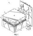
- FIG. 1is a perspective view of a plasma processing system in accordance with an embodiment of the invention
- FIG. 2is a side view of the plasma processing system of FIG. 1 ;
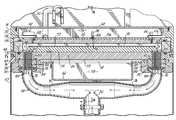
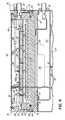
- FIG. 3Ais a front cross-sectional view of the plasma processing system of FIGS. 1 and 2 ;
- FIG. 3Bis a cross-sectional view similar to FIG. 3A shown with the enclosure lid engaged with the enclosure base;
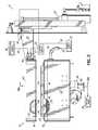
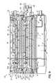
- FIG. 4is a side cross sectional view of the plasma processing system of FIG. 1 ;
- FIG. 5is an exploded view of the enclosure base of the plasma processing system of FIG. 1 ;
- FIG. 6is an exploded view of the enclosure lid of the plasma processing system of FIG. 1 ;
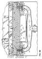
- FIG. 7is a top view taken generally along line 7 - 7 in FIG. 3A ;
- FIGS. 7A and 7Bare top views similar to FIG. 7 in accordance with alternative embodiments of the invention.
- FIGS. 8 and 9are front and side cross-sectional views similar to FIGS. 3A and 4 of a plasma processing system in accordance with an alternative embodiment of the invention.
- a plasma processing system 10generally includes an enclosure 12 having a lid 14 and a base 16 upon which the lid 14 rests, a pair of support arms 18 , 20 depending from the lid 14 , an upper electrode 22 , and a lower electrode 24 .
- the processing system 10further includes a separating member or ring 26 positioned between the upper and lower electrodes 22 , 24 and contacting confronting faces about the perimeter of the upper and lower electrodes 22 , 24 .
- the confronting faces of the electrodes 22 , 24are generally planar and parallel plates and have approximately identical surface areas.
- a shroud 25extends downwardly from the base 16 toward the surface supporting system 10 .
- a lifting device 28Mechanically coupled with the support arms 18 , 20 is a lifting device 28 , illustrated as a pneumatic cylinder, that vertically lifts and lowers the lid 14 relative to the base 16 between a raised position ( FIG. 3A ) and a lowered position ( FIG. 3B ).
- a processing region 40FIG. 3B
- an environmentmay be established in the processing region 40 that is suitable for plasma processing a substrate 55 positioned in the processing region 40 .
- the inventioncontemplates that the processing region 40 may be accessed in any alternative manner understood by persons of ordinary skill in the art, such as a hinged connection that pivots the lid 14 relative to base 16 .
- the processing system 10may be provided with an input carrier that provides unprocessed substrates 55 , an output carrier that receives processed substrates 55 , and a transfer arm or the like for transferring substrates 55 from the input carrier to the process chamber and from the process chamber to the output carrier.
- a plurality of discrete substrates 55may be introduced in such a way that each substrate 55 within the plurality is independently introduced into the processing system 10 or in such a way that one or more substrates 55 within the plurality are jointly introduced into the processing system 10 .
- Discrete substrates 55may also be positioned on a support or carrier and transported thereon into the processing system.
- the processing system 10may comprise a single process station among multiple process stations that cooperate to sequentially process multiple substrates 55 moving in an assembly line fashion among the multiple process stations.
- a power supply 30which is coupled with the electrodes 22 , 24 by shielded coaxial cables or transmission lines 32 , 34 , respectively, controls the power level and frequency of operation of the electrodes 22 , 24 .
- the power supply 30may be an alternating current power supply operating at an extremely low frequency, such as 50 Hz and 60 Hz, at a high radio frequency, such as 40 kHz and 13.56 MHz, at a medium radio frequency, such as 1 kHz, or at a microwave frequency, such as 2.4 GHz.
- the power supply 30may also operate at dual frequencies superimposed upon one another.
- the power supply 30may be a direct current (DC) power supply in which the plasma is non-oscillating.
- power supply 30may supply a radio frequency (RF) power component that provides a dense plasma and a DC power component that independently increases ion energy without effecting the plasma density.
- RFradio frequency
- the power supply 30may operated at one or more radio frequencies and include an impedance matching network (not shown) that measures reflected power from the load represented by the electrodes 22 , 24 and plasma confined therebetween back to the power supply 30 .
- the impendence matching networkadjusts the frequency of operation of power supply 30 to minimize the reflected power.
- the construction of such matching networksis understood by a person of ordinary skill in the art.
- the impedance matching networkmay tune the matching network by changing the capacitance of variable capacitors within the matching network to match the impedance of the power supply 30 to the impedance of the load as the load changes.
- the power and voltage levels and operating frequency(ies)may vary of course, depending upon the particular application.
- a vacuum pump 36continuously pumps byproduct generated by the plasma process and non-reacted process gas from the processing region 40 , when the plasma processing system 10 is operating, through a vacuum manifold 38 .
- the vacuum pump 36is operative to maintain the total pressure in the processing region 40 at a subatmospheric level low enough to facilitate creation of a plasma.
- pressures suitable for plasma formationrange from about twenty (20) millitorr to greater than about fifty (50) torr.
- the pressure within the processing region 40is controlled in accordance with a particular desired plasma process and primarily consists of partial pressure contributions from the process gas, which may comprise one or more individual gas species, supplied to the evacuated processing region 40 .
- the plasma processing system 10includes a microprocessor-based controller that is programmed to control the operation of, among other components, the power supply 30 , the vacuum pump 36 , and the process gas supply 114 .
- the controllerregulates the power levels, voltages, currents and frequencies of the power supply 30 and orchestrates the provision of process gas from process gas supply 114 and the pumping rate of vacuum pump 36 to define a suitable pressure in processing region 40 in accordance with the particular plasma process and application.
- the power applied between the electrodes 22 , 24 by power supply 30produces an electromagnetic field in a processing region 40 ( FIGS. 3B and 4 ) defined between the two electrodes 22 , 24 , as described below, when the lid 14 and base 16 are contacting and an environment suitable for plasma processing is provided.
- the electromagnetic fieldexcites the process gas present in the processing region to a plasma state, which is sustained by the application of power from power supply 30 for the duration of the plasma treatment.
- the plasmais configured to perform the desired surface modification of the substrate 55 by selecting parameters such as the chemistry of the process gas, the pressure inside the processing region 40 , and the amount of power and/or frequency applied to the electrodes 22 , 24 .
- the processing system 10may include an end point recognition system (not shown) that automatically recognizes when a plasma process (e.g., an etching process) has reached a predetermined end point or, alternatively, plasma processes may be timed based upon an empirically-determined process time.
- the upper electrode 22is suspended from the upper housing by a plurality of electrically insulating spacers, of which spacers 42 and 44 are visible in FIG. 3A and spacer 46 is visible in FIG. 4 .
- insulating spacers similar to spacers 42 , 44 and 46are positioned between each corner of upper electrode 22 and each corner of the lid 14 .
- a retaining ring 48Secured by conventional fasteners to the perimeter of the lid 14 is a retaining ring 48 that operates to secure the separating ring 26 to the lid 14 .
- the upper electrode 22 and the retaining ring 48move along with the lid 14 when the lid 14 is moved by the lifting device 28 between the raised and lowered positions relative to the base 16 .
- a sealing member 50is compressed between separating 26 and the upper electrode 22 by a vertical force applied by the retaining ring 48 when fastened to the lid 14 .
- a sealing member 52is compressed between the separating ring 26 and a perimeter of the lower electrode 24 .
- the sealing members 50 , 52are illustrated as conventional elastomeric O-rings, although the invention is not so limited.
- a substrate holder 54configured to support either one or more substrates or one or more carriers each bearing one or more substrates 55 at locations inside the processing region 40 suitable for plasma treatment.
- the substrate holder 54has a good electrical contact with the lower electrode 24 so that the substrate holder 54 and substrates 55 are at the same potential as the lower electrode 24 .
- the substrate holder 54may be at a floating potential and electrically insulated from the lower electrode 24 .
- the inventionalso contemplates that the substrate 55 may be supported from the upper electrode 22 or by the separating ring 26 .
- the processing region 40is defined as the space bounded vertically between the inwardly-facing horizontal surfaces of the electrodes 22 , 24 and bounded laterally inside the inwardly-facing vertical surface of the sidewall defined by the separating ring 26 .
- the base 16includes an opening 61 over which is positioned a base thin-walled metallic closure 62 , which constitutes a component of the enclosure 12 .
- An unpumped atmospheric-pressure cavity or air gap 58is defined between the lower electrode 24 and the assembly of the base 16 and the closure 62 , respectively.
- Another unpumped atmospheric-pressure cavity or air gap 56is defined between the lid 14 , a lid cover 60 removable from lid 14 , and the upper electrode 22 .
- the air gaps 56 , 58are dimensioned to minimize energy loss from the electrodes 22 , 24 to the lid 14 , base 16 and closure 62 and are coupled together as a single, continuous air-filled space by portions of gaps 56 , 58 encircling the perimeter of the electrodes 22 , 24 and separating ring 26 , as best depicted in FIG. 3B .
- a conducting member 64captured between the respective perimeters of the lid 14 and base 16 , which are metallic, supplies a good electrical contact between the lid 14 and base 16 .
- the lid 14 , base 16 , cover 60 , and closure 62collectively define a substantially closed electrically conducting shell, which acts as a shield to confine power supplied to the electrodes 22 , 24 within the interior of the enclosure 12 .
- Transmission line 34which is electrically coupled in a known manner with the lower electrode 24 , is routed through opening 61 to lower electrode 24 .
- Transmission line 32enters the lid 14 at a location between the removable lid cover 60 and the upper electrode 22 , and is electrically coupled in a known manner with the upper electrode 22 . If both electrodes 22 , 24 are coupled with the power supply 30 and the power supply 30 is an alternating current power supply, one of the electrodes 22 , 24 may be driven 180° out of phase from the other of the electrodes 22 , 24 so that both electrodes 22 , 24 are powered. Alternatively, one of the electrodes 22 , 24 may be grounded and the other of the electrodes 22 , 24 may be powered.
- an appropriate cooling fluidmay be circulated through these air gaps 56 , 58 for cooling the processing system 10 and, in particular, for cooling the electrodes 22 , 24 .
- a fitting 57FIG. 2
- a forced flow of a coolantsuch as air, may be introduced from the coolant supply 59 to air gap 56 via fitting 57 to establish a continuous coolant flow about the electrodes 22 , 24 through air gaps 56 , 58 .
- Air gap 58is structured to provide an exhaust path for the flowing coolant to the open environment about the processing system 10 .
- the volume bounded by the electrodes 22 , 24 and the separating ring 26constitutes the processing region 40 and represents the only volume, aside from the vacuum manifold 38 , in the processing system 10 that is evacuated by the vacuum pump 36 and, hence, represents the vacuum envelope of the plasma processing system 10 .
- Thisis in marked contrast to conventional plasma processing systems in which electrodes are positioned inside a vacuum chamber with a significant evacuated volume surrounding the electrodes in which the process gas may be excited to provide an unconfined plasma that uses available power but is otherwise not available for processing workpieces 55 positioned between the electrodes 22 , 24 .
- the effective evacuated volume of system 10is significantly smaller than the evacuated volume of conventional processing chambers.
- Thisprovides multiple benefits including, but not limited to, an increased plasma density, a significant reduction in the time required to evacuate the processing chamber to a pressure suitable for exciting the plasma, and a significant reduction in the time required to bleed or vent the processing chamber to atmospheric pressure. These benefits contribute to an increased throughput with decreased cost of operation and a reduced processing time required to provide a targeted plasma treatment as compared with conventional plasma processing systems.
- the electrodes 22 , 24are formed from an electrically-conductive material, such as aluminum.
- the separating ring 26is formed from a non-conducting dielectric material that is able to withstand the plasma environment inside the processing region 40 without unduly contaminating the processed substrate 55 . Generally, this implies that the material forming the separating ring 26 should be substantially resistant to etching by the plasma present in the processing region 40 .
- the separating ring 26defines a vertical sidewall of non-conductive material, in addition to providing the vacuum seal between the electrodes 22 , 24 .
- the absence of a conventional vacuum chambereliminates or, at the least, significant reduces external field effects. More specifically, the electrodes 22 , 24 of plasma processing system 10 are not surrounded by grounded metallic walls characterizing a conventional vacuum chamber. Instead, the non-conducting separating ring 26 effectively operates as the vertical sidewall boundary of the processing region 40 . Therefore, external field effects are minimized or absent and the equipotential electric field lines are uniform across the entire surface of the substrate 55 without fringing at the electrode edges, which allows plasma processing to proceed in a uniform manner across the substrate 55 .
- jade glassi.e., calcium magnesium iron silicate or sodium aluminum iron silicate
- another ceramic materialsuch as alumina, float glass, silica or quartz, may also be used.
- the dielectric material constituting separating ring 26may any of a number of polymeric fluorocarbon materials including but not limited to polytetrafluoroethylene (PTFE), the homopolymer of tetrafluoroethylene sold under the trademark TEFLON by DuPont; perfluorinated ethylene-propylene (FEP), the copolymer of tetrafluoroethylene and hexafluoropropylene sold under the trademark TEFLON FEP by DuPont; perfluoroalkoxy fluorocarbon resin (PFA), the copolymer of tetrafluoroethylene-perfluorovinyl ether sold under the trademark TEFLON PFA by DuPont; or ethylene tetrafluoroethylene (ETFE), the copolymer of ethylene and tetrafluoroethylene sold under the trademark TEFZEL by DuPont.
- PTFEpolytetrafluoroethylene
- FEPperfluorinated ethylene-propylene
- separating ring 26may be appropriate, for example, in etching applications with plasma species capable of chemically attacking ceramics. Because the separating ring 26 constitutes a portion of the vacuum envelope of the processing region 40 , the separating ring 26 should be engineered with a strength sufficient to withstand the external forces arising from the pressure differential between the evacuated processing region 40 and the atmospheric pressure in air gaps 56 , 58 .
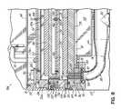
- the lower electrode 24includes a laterally-spaced pair of vacuum ports 66 , 68 each of which is positioned to coincide spatially with one of flanged ports 70 , 72 at the ends of opposed arms 74 , 76 , respectively, of the vacuum manifold 38 .
- the flanged ports 70 , 72are fastened to the lower electrode 24 by bolts (not shown) to compress respective sealing members 78 , 80 and thereby form vacuum seals.
- the arms 74 , 76converge at a vertical tubing section 82 that leads to the vacuum pump 36 .
- Received partially in the opening in flanged port 70 and partially inside of a mounting plate 84 surrounding port 70is an insert 88 .
- an insert 90received partially in the opening in flanged port 72 and partially inside of a mounting plate 86 surrounding port 72 is an insert 90 .
- a centering ring 92 , 94is also positioned inside a corresponding one of the flanged ports 70 , 72 .
- Disposed between the base 16 and the lower electrode 24are manifold mounting spacers 96 , 98 each of which has a central opening that coincides with one of the vacuum ports 66 , 68 .
- the identical manifold mounting spacers 96 , 98are each formed from an electrically insulating material, such as a thermoplastic elastomer (TPE), and their presence contributes to isolating the lower electrode 24 from the base 16 of the enclosure 12 .
- the identical inserts 88 , 90which are each formed from an electrically insulating material such as a ceramic with a relatively high dielectric constant, serve to electrically isolate the lower electrode 24 from the base 16 of the enclosure 12 and the flanged ports 70 , 72 of the vacuum manifold 38 .
- the inserts 88 , 90 and, to a minor extent, the centering rings 92 , 94fill otherwise empty spaces at the juncture between the lower electrode 24 and the vacuum manifold 38 .
- the lower electrode 24 and the vacuum manifold 38are spaced apart due to the electrical isolation needed between the lower electrode 24 and the base 16 of enclosure 12 .
- the presence of the inserts 88 , 90 and centering rings 92 , 94prevents plasma excitation in these otherwise unfilled spaces between the vacuum manifold 38 and the lower electrode 24 .
- the inserts 88 , 90effectively operate as a charged particle filter that confines the plasma to the processing region 40 .
- each of the vacuum ports 66 , 68 in the lower electrode 24includes an array of passages 100 , respectively, which are registered with a corresponding array of passages 102 , respectively, formed in a corresponding one of the inserts 88 , 90 and a corresponding array of passages 104 , respectively, formed in a corresponding one of the centering rings 92 , 94 .
- the vacuum pump 36exhausts byproduct generated by the plasma process and non-reacted gas from the processing region 40 into the vacuum manifold 38 through the registered passages 100 , 102 , 104 .
- the arrangement and dimensions of the passages 100 , 102 , 104which typically have substantially identical arrangement and dimensions, are selected to maximize pumping conductance while simultaneously preventing plasma excitation based on the hollow cathode effect. As a result, the plasma is confined to the processing region 40 , which makes efficient use of the input excitation power.
- the pattern and configuration of the passages 100 , 102 , 104is not limited to the illustrated embodiment in FIG. 7 but, instead, is contemplated to include any pattern and configuration that provides suitable pumping conductance without plasma excitation.
- the passages 100 , 102 , 104are spaced apart in a direction normal to that of the flow of the exhausting gases.
- the passages 102 a in a representative insert 88 a and the passages 100 a in a representative vacuum port 66 a of a lower electrode 24 aare configured as a set of parallel slots.
- the passages in a centering ringare configured to coincide with the passages 100 a , 102 a .
- the passages 102 b in a representative insert 88 b and the passages 100 b in a representative vacuum port 66 b of a lower electrode 24 bare configured as a set of concentric curved slots.
- the passages in a centering ringare configured to coincide with the passages 100 b , 102 b.
- a gas inlet plate 106fastened to an upper horizontal surface of the upper electrode 22 is a gas inlet plate 106 .
- a gas port 108( FIG. 4 ) coupled by a conduit 110 with a fitting 112 .
- Fitting 112is further coupled by a delivery line 113 with a process gas supply 114 ( FIG. 2 ).
- the delivery line 113 and process gas supply 114may include a mass flow controller and a flow measurement device (not shown) that cooperate for regulating the flow rate of each individual process gas to the processing region 40 .
- a planar surface 106 a of the gas inlet plate 106 facing the upper electrode 22includes a plurality of recessed radial channels 116 that intersect at and diverge away from the location of the gas port 108 . Extending through the upper electrode 22 is a plurality of perforations or gas openings 118 arranged in a pattern such that each gas opening 118 is registered with one of the radial channels 116 in the gas inlet plate 106 when the gas inlet plate 106 is fastened to the upper electrode 22 .
- a conventional sealing member 120illustrated as an elastomeric o-ring, provides a seal about the adjacent perimeters of the gas inlet plate 106 and the upper electrode 22 .
- Process gas supplied to the gas port 108is distributed among the radial channels 116 to the gas openings 118 .
- the process gasis admitted to the processing region 40 through gas openings 118 positioned with spaced-apart locations above the lower electrode 24 and across the substrate 55 supported on the substrate holder 54 .
- the gas distributionmay be tailored for a specific processing application by inserting a plug 122 into one or more of the gas openings 118 that is effective to block process gas flow.
- the gas openings 118may be threaded and the plug 122 may be an appropriately-sized set screw.
- the adjustment of the gas distributionmay be empirically determined by examining the process uniformity on processed substrates 55 .
- the flow of process gas into the processing region 40 and the pumping rate of vacuum pump 36are coordinated to maintain the total gas pressure in the processing region 40 at a level low enough to facilitate plasma creation from the partial pressure of process gas.
- the gas distribution system of the inventionpromotes uniform distribution of the process gas across the substrate 55 and has the flexibility to permit adjustments to the pattern of gas distribution.
- the process gasmay be supplied to the processing region 40 by a different type of gas distribution system, such as a gas distribution ring, gas injectors, a single gas port, etc.
- electrode 22may be configured to produce an ion-free or downstream plasma in the processing region 30 .
- a suitable configuration for electrode 22is disclosed in commonly-owned and currently pending application Ser. No. 10/324,436, filed Dec. 20, 2002 in the name of James Scott Tyler et al. and entitled “Plasma Treatment System”, which is hereby incorporated by reference herein in its entirety.
- references herein to terms such as “vertical”, “horizontal”, etc.are made by way of example, and not by way of limitation, to establish a frame of reference.
- the term “horizontal” as used hereinis defined as a plane substantially parallel to a plane containing one of the confronting surfaces of the electrodes 22 , 24 , regardless of orientation.
- the term “vertical”refers to a direction perpendicular to the horizontal, as just defined. Terms, such as “upper”, “lower”, “on”, “above”, “below”, “side” (as in “sidewall”), “higher”, “lower”, “over”, “beneath” and “under”, are defined with respect to the horizontal plane. It is understood various other frames of reference may be employed without departing from the spirit and scope of the invention as a person of ordinary skill will appreciate that the defined frame of reference is relative as opposed to absolute.
- a plasma processing system 10 afeatures a second processing level stacked vertically in relationship with the first processing level. This increases the workpiece capacity of system 10 a for a single processing operation and expands the system throughput as compared with system 10 ( FIGS. 1-7 ).
- the second levelis provided by inserting an intermediate electrode 130 between upper and lower electrodes 22 , 24 and adding an additional separating member or ring 132 that is substantially identical to separating ring 26 . Electrode 130 and separating ring 132 are carried by a frame 134 and electrically insulated from the frame 134 by electrically insulating member 136 ( FIG. 8 ).
- a lifting devicesimilar to lifting device 28 ( FIGS. 1 and 2 ) vertically lifts and lowers the frame 134 relative to the base 16 after the lid 14 is moved to a raised position ( FIG. 3A ).
- Thisprovides access to a processing space consisting of, when the lid 14 and frame 134 are in a lowered position ( FIGS. 8 and 9 ), a first portion 40 a bounded by the upper electrode 22 , the separating ring 26 , and the intermediate electrode 130 and a second portion 40 b bounded by the lower electrode 24 , the intermediate electrode 130 and the separating ring 132 .
- the frame 134constitutes a portion of the enclosure 12 in this alternative embodiment and is separated from the electrode 130 and separating ring 132 by an air gap 133 that is continuous with air gaps 56 , 58 .
- a conducting member 138which is similar or identical to conducting member 64 , is captured between the respective perimeters of the frame 134 and lid 14 .
- Conducting member 64now is captured between the respective perimeters of frame 134 and base 16 .
- the lid 14 , base 16 , closure 62 and frame 134collectively define a substantially closed electrically conducting shell, which acts as a shield to confine power supplied to the electrodes 22 , 24 within the interior of the enclosure 12 .
- processing space 40 a,bcommunicate by an array of passages 135 ( FIG. 9 ) arranged about the periphery of the intermediate electrode 130 .
- Processing space 40 bis evacuated directly through vacuum ports 66 , 68 and processing space 40 a is pumped through passages 135 .
- processing space 40 a,brepresents the only evacuated volume of system 10 and provides various advantages and benefits identical to those described above for system 10 .
- the inventionis not limited to two processing levels as additional levels may be introduced in a consistent manner.
- a sealing member 50 awhich is similar or identical to sealing member 50 , is compressed between separating ring 132 and a perimeter of the lower section 130 a of the intermediate electrode 130 by a vertical force applied by a retaining ring 137 .
- a sealing member 52 awhich is similar or identical to sealing member 52 , is compressed between the separating ring 26 and a perimeter of the upper section 130 b of the intermediate electrode 130 . Sealing member 52 is now compressed between separating ring 132 and the lower electrode 24 .
- the frame 134is mounted to a lifting device (not shown) that lifts an assembly including electrode 130 and separating ring 132 relative to base 14 . After the lid 14 of enclosure 12 is lifted relative to electrode 130 , the assembly including electrode 130 and separating ring 132 may be moved relative to base 16 for accessing a substrate holder 138 mounted to electrode 130 .
- the substrate holder 140which is identical to substrate holder 54 , is configured to support either one or more substrates 55 or one or more carriers each bearing one or more substrates 55 at locations suitable for plasma treatment inside the processing region 40 a . Similarly, substrate holder 54 now holds substrates 55 supports either one or more substrates 55 or one or more carriers each bearing one or more substrates 55 at locations suitable for plasma treatment inside the processing region 40 b.
- the intermediate electrode 130includes a lower section 130 a configured similar to upper electrode 22 with a gas distribution system that evenly and uniformly distributes process gas into processing space 40 b and an upper section 130 carrying substrate holder 140 .
- the lower section 130 a of the intermediate electrode 130includes a gas inlet plate 142 , which is similar or identical to gas inlet plate 106 , having a gas port 144 coupled by a conduit 146 with a fitting 148 , which is further coupled with process gas supply 114 ( FIG. 2 ).
- a planar surface of the gas inlet plate 142 facing the lower section 130 a of intermediate electrode 130includes a plurality of recessed radial channels 150 , which are similar or identical to channels 116 , that intersect at and diverge away from the location of the gas port 144 .
- Extending through the lower section 130 ais a plurality of perforations or gas openings 152 , which are similar or identical to gas openings 118 , arranged in a pattern such that each gas opening 152 is registered with one of the radial channels 150 in the gas inlet plate 142 .
- a conventional sealing member 154illustrated as an elastomeric o-ring, provides a seal about the adjacent perimeters of the gas inlet plate 142 and the lower section 130 a of intermediate electrode 130 .
- gas openings 118now uniformly distribute process gas across the confronting surface of workpiece 55 in processing region 40 a and, in a similar manner, gas openings 152 distribute process gas across the confronting surface of workpiece 55 in processing region 40 b.
- a transmission line 156is electrically coupled in a known manner with the intermediate electrode 130 .
- all three electrodes 22 , 24 , and 130are coupled with the power supply 30 and, if the power supply 30 is an alternating current power supply, the middle electrode 130 is driven 180° out of phase from the other electrodes 22 , 24 .
Landscapes
- Physics & Mathematics (AREA)
- Engineering & Computer Science (AREA)
- Plasma & Fusion (AREA)
- Chemical & Material Sciences (AREA)
- Analytical Chemistry (AREA)
- Plasma Technology (AREA)
- Chemical Vapour Deposition (AREA)
- Drying Of Semiconductors (AREA)
- Physical Or Chemical Processes And Apparatus (AREA)
Abstract
Description
Claims (14)
Priority Applications (7)
| Application Number | Priority Date | Filing Date | Title |
|---|---|---|---|
| US10/710,457US7845309B2 (en) | 2004-07-13 | 2004-07-13 | Ultra high speed uniform plasma processing system |
| EP05014248AEP1617457B1 (en) | 2004-07-13 | 2005-06-30 | Ultra high speed uniform plasma processing system |
| TW094122856ATWI392402B (en) | 2004-07-13 | 2005-07-06 | Ultra-high speed uniform plasma processing system |
| SG200717678-7ASG137851A1 (en) | 2004-07-13 | 2005-07-06 | Ultra high speed uniform plasma processing system |
| SG200504851ASG119365A1 (en) | 2004-07-13 | 2005-07-06 | Ultra high speed uniform plasma processing system |
| JP2005204419AJP5054901B2 (en) | 2004-07-13 | 2005-07-13 | Ultra-high speed uniform plasma processing equipment |
| CN200510083627.9ACN1728916B (en) | 2004-07-13 | 2005-07-13 | Ultra-high-speed uniform plasma treatment system |
Applications Claiming Priority (1)
| Application Number | Priority Date | Filing Date | Title |
|---|---|---|---|
| US10/710,457US7845309B2 (en) | 2004-07-13 | 2004-07-13 | Ultra high speed uniform plasma processing system |
Publications (2)
| Publication Number | Publication Date |
|---|---|
| US20060011299A1 US20060011299A1 (en) | 2006-01-19 |
| US7845309B2true US7845309B2 (en) | 2010-12-07 |
Family
ID=35115691
Family Applications (1)
| Application Number | Title | Priority Date | Filing Date |
|---|---|---|---|
| US10/710,457Expired - Fee RelatedUS7845309B2 (en) | 2004-07-13 | 2004-07-13 | Ultra high speed uniform plasma processing system |
Country Status (6)
| Country | Link |
|---|---|
| US (1) | US7845309B2 (en) |
| EP (1) | EP1617457B1 (en) |
| JP (1) | JP5054901B2 (en) |
| CN (1) | CN1728916B (en) |
| SG (2) | SG137851A1 (en) |
| TW (1) | TWI392402B (en) |
Cited By (119)
| Publication number | Priority date | Publication date | Assignee | Title |
|---|---|---|---|---|
| US20050269031A1 (en)* | 2002-04-19 | 2005-12-08 | Nordson Corporation | Plasma treatment system |
| US20090133837A1 (en)* | 2004-02-25 | 2009-05-28 | Advanced Display Process Engineering Co., Ltd. | Apparatus for manufacturing flat-panel display |
| US20090314432A1 (en)* | 2008-06-23 | 2009-12-24 | Tokyo Electron Limited | Baffle plate and substrate processing apparatus |
| US20100021631A1 (en)* | 2008-07-24 | 2010-01-28 | Yoshikazu Moriyama | Coating apparatus and coating method |
| US20110031214A1 (en)* | 2009-08-06 | 2011-02-10 | Jisoo Kim | Vacuum processing chambers incorporating a moveable flow equalizer |
| US20120034786A1 (en)* | 2010-08-04 | 2012-02-09 | Lam Research Corporation | Plasma Processing Chamber with Dual Axial Gas Injection and Exhaust |
| US20120266821A1 (en)* | 2005-01-18 | 2012-10-25 | Asm America, Inc. | Reaction system for growing a thin film |
| US20140057447A1 (en)* | 2012-08-02 | 2014-02-27 | Applied Materials, Inc. | Semiconductor processing with dc assisted rf power for improved control |
| TWI505356B (en)* | 2012-05-14 | 2015-10-21 | Psk Inc | Baffle and apparatus for treating substrate with the same |
| US9184028B2 (en) | 2010-08-04 | 2015-11-10 | Lam Research Corporation | Dual plasma volume processing apparatus for neutral/ion flux control |
| US9425058B2 (en) | 2014-07-24 | 2016-08-23 | Applied Materials, Inc. | Simplified litho-etch-litho-etch process |
| US9437451B2 (en) | 2012-09-18 | 2016-09-06 | Applied Materials, Inc. | Radical-component oxide etch |
| US9449845B2 (en) | 2012-12-21 | 2016-09-20 | Applied Materials, Inc. | Selective titanium nitride etching |
| US9449846B2 (en) | 2015-01-28 | 2016-09-20 | Applied Materials, Inc. | Vertical gate separation |
| US9472412B2 (en) | 2013-12-02 | 2016-10-18 | Applied Materials, Inc. | Procedure for etch rate consistency |
| US9472417B2 (en) | 2013-11-12 | 2016-10-18 | Applied Materials, Inc. | Plasma-free metal etch |
| US9478432B2 (en) | 2014-09-25 | 2016-10-25 | Applied Materials, Inc. | Silicon oxide selective removal |
| US9478434B2 (en) | 2014-09-24 | 2016-10-25 | Applied Materials, Inc. | Chlorine-based hardmask removal |
| US9493879B2 (en) | 2013-07-12 | 2016-11-15 | Applied Materials, Inc. | Selective sputtering for pattern transfer |
| US9496167B2 (en) | 2014-07-31 | 2016-11-15 | Applied Materials, Inc. | Integrated bit-line airgap formation and gate stack post clean |
| US9502258B2 (en) | 2014-12-23 | 2016-11-22 | Applied Materials, Inc. | Anisotropic gap etch |
| US9499898B2 (en) | 2014-03-03 | 2016-11-22 | Applied Materials, Inc. | Layered thin film heater and method of fabrication |
| US9553102B2 (en) | 2014-08-19 | 2017-01-24 | Applied Materials, Inc. | Tungsten separation |
| US9564296B2 (en) | 2014-03-20 | 2017-02-07 | Applied Materials, Inc. | Radial waveguide systems and methods for post-match control of microwaves |
| US9576809B2 (en) | 2013-11-04 | 2017-02-21 | Applied Materials, Inc. | Etch suppression with germanium |
| US9607856B2 (en) | 2013-03-05 | 2017-03-28 | Applied Materials, Inc. | Selective titanium nitride removal |
| US9659753B2 (en) | 2014-08-07 | 2017-05-23 | Applied Materials, Inc. | Grooved insulator to reduce leakage current |
| US9659792B2 (en) | 2013-03-15 | 2017-05-23 | Applied Materials, Inc. | Processing systems and methods for halide scavenging |
| US9691645B2 (en) | 2015-08-06 | 2017-06-27 | Applied Materials, Inc. | Bolted wafer chuck thermal management systems and methods for wafer processing systems |
| US9721789B1 (en) | 2016-10-04 | 2017-08-01 | Applied Materials, Inc. | Saving ion-damaged spacers |
| US9728437B2 (en) | 2015-02-03 | 2017-08-08 | Applied Materials, Inc. | High temperature chuck for plasma processing systems |
| US9741593B2 (en) | 2015-08-06 | 2017-08-22 | Applied Materials, Inc. | Thermal management systems and methods for wafer processing systems |
| US9754800B2 (en) | 2010-05-27 | 2017-09-05 | Applied Materials, Inc. | Selective etch for silicon films |
| US9768034B1 (en) | 2016-11-11 | 2017-09-19 | Applied Materials, Inc. | Removal methods for high aspect ratio structures |
| US9773648B2 (en) | 2013-08-30 | 2017-09-26 | Applied Materials, Inc. | Dual discharge modes operation for remote plasma |
| US9842744B2 (en) | 2011-03-14 | 2017-12-12 | Applied Materials, Inc. | Methods for etch of SiN films |
| US9865484B1 (en) | 2016-06-29 | 2018-01-09 | Applied Materials, Inc. | Selective etch using material modification and RF pulsing |
| US9881805B2 (en) | 2015-03-02 | 2018-01-30 | Applied Materials, Inc. | Silicon selective removal |
| US9885117B2 (en) | 2014-03-31 | 2018-02-06 | Applied Materials, Inc. | Conditioned semiconductor system parts |
| US9934942B1 (en) | 2016-10-04 | 2018-04-03 | Applied Materials, Inc. | Chamber with flow-through source |
| US9947549B1 (en) | 2016-10-10 | 2018-04-17 | Applied Materials, Inc. | Cobalt-containing material removal |
| US9966240B2 (en) | 2014-10-14 | 2018-05-08 | Applied Materials, Inc. | Systems and methods for internal surface conditioning assessment in plasma processing equipment |
| US9978564B2 (en) | 2012-09-21 | 2018-05-22 | Applied Materials, Inc. | Chemical control features in wafer process equipment |
| US10026621B2 (en) | 2016-11-14 | 2018-07-17 | Applied Materials, Inc. | SiN spacer profile patterning |
| US10043674B1 (en) | 2017-08-04 | 2018-08-07 | Applied Materials, Inc. | Germanium etching systems and methods |
| US10043684B1 (en) | 2017-02-06 | 2018-08-07 | Applied Materials, Inc. | Self-limiting atomic thermal etching systems and methods |
| US10049891B1 (en) | 2017-05-31 | 2018-08-14 | Applied Materials, Inc. | Selective in situ cobalt residue removal |
| US10062575B2 (en) | 2016-09-09 | 2018-08-28 | Applied Materials, Inc. | Poly directional etch by oxidation |
| US10062578B2 (en) | 2011-03-14 | 2018-08-28 | Applied Materials, Inc. | Methods for etch of metal and metal-oxide films |
| US10062585B2 (en) | 2016-10-04 | 2018-08-28 | Applied Materials, Inc. | Oxygen compatible plasma source |
| US10062579B2 (en) | 2016-10-07 | 2018-08-28 | Applied Materials, Inc. | Selective SiN lateral recess |
| US10062587B2 (en) | 2012-07-18 | 2018-08-28 | Applied Materials, Inc. | Pedestal with multi-zone temperature control and multiple purge capabilities |
| US10128086B1 (en) | 2017-10-24 | 2018-11-13 | Applied Materials, Inc. | Silicon pretreatment for nitride removal |
| US10163696B2 (en) | 2016-11-11 | 2018-12-25 | Applied Materials, Inc. | Selective cobalt removal for bottom up gapfill |
| US10170336B1 (en) | 2017-08-04 | 2019-01-01 | Applied Materials, Inc. | Methods for anisotropic control of selective silicon removal |
| US10224210B2 (en) | 2014-12-09 | 2019-03-05 | Applied Materials, Inc. | Plasma processing system with direct outlet toroidal plasma source |
| US10242908B2 (en) | 2016-11-14 | 2019-03-26 | Applied Materials, Inc. | Airgap formation with damage-free copper |
| US10256112B1 (en) | 2017-12-08 | 2019-04-09 | Applied Materials, Inc. | Selective tungsten removal |
| US10256079B2 (en) | 2013-02-08 | 2019-04-09 | Applied Materials, Inc. | Semiconductor processing systems having multiple plasma configurations |
| US10283321B2 (en) | 2011-01-18 | 2019-05-07 | Applied Materials, Inc. | Semiconductor processing system and methods using capacitively coupled plasma |
| US10283324B1 (en) | 2017-10-24 | 2019-05-07 | Applied Materials, Inc. | Oxygen treatment for nitride etching |
| US10297458B2 (en) | 2017-08-07 | 2019-05-21 | Applied Materials, Inc. | Process window widening using coated parts in plasma etch processes |
| US10319649B2 (en) | 2017-04-11 | 2019-06-11 | Applied Materials, Inc. | Optical emission spectroscopy (OES) for remote plasma monitoring |
| US10319600B1 (en) | 2018-03-12 | 2019-06-11 | Applied Materials, Inc. | Thermal silicon etch |
| US10319739B2 (en) | 2017-02-08 | 2019-06-11 | Applied Materials, Inc. | Accommodating imperfectly aligned memory holes |
| US10354889B2 (en) | 2017-07-17 | 2019-07-16 | Applied Materials, Inc. | Non-halogen etching of silicon-containing materials |
| US10358721B2 (en)* | 2015-10-22 | 2019-07-23 | Asm Ip Holding B.V. | Semiconductor manufacturing system including deposition apparatus |
| US10403507B2 (en) | 2017-02-03 | 2019-09-03 | Applied Materials, Inc. | Shaped etch profile with oxidation |
| US10424485B2 (en) | 2013-03-01 | 2019-09-24 | Applied Materials, Inc. | Enhanced etching processes using remote plasma sources |
| US10424463B2 (en) | 2015-08-07 | 2019-09-24 | Applied Materials, Inc. | Oxide etch selectivity systems and methods |
| US10431429B2 (en) | 2017-02-03 | 2019-10-01 | Applied Materials, Inc. | Systems and methods for radial and azimuthal control of plasma uniformity |
| US10468267B2 (en) | 2017-05-31 | 2019-11-05 | Applied Materials, Inc. | Water-free etching methods |
| US10465294B2 (en) | 2014-05-28 | 2019-11-05 | Applied Materials, Inc. | Oxide and metal removal |
| US10490406B2 (en) | 2018-04-10 | 2019-11-26 | Appled Materials, Inc. | Systems and methods for material breakthrough |
| US10497573B2 (en) | 2018-03-13 | 2019-12-03 | Applied Materials, Inc. | Selective atomic layer etching of semiconductor materials |
| US10504700B2 (en) | 2015-08-27 | 2019-12-10 | Applied Materials, Inc. | Plasma etching systems and methods with secondary plasma injection |
| US10504754B2 (en) | 2016-05-19 | 2019-12-10 | Applied Materials, Inc. | Systems and methods for improved semiconductor etching and component protection |
| US10522371B2 (en) | 2016-05-19 | 2019-12-31 | Applied Materials, Inc. | Systems and methods for improved semiconductor etching and component protection |
| US10541184B2 (en) | 2017-07-11 | 2020-01-21 | Applied Materials, Inc. | Optical emission spectroscopic techniques for monitoring etching |
| US10541246B2 (en) | 2017-06-26 | 2020-01-21 | Applied Materials, Inc. | 3D flash memory cells which discourage cross-cell electrical tunneling |
| US10546729B2 (en) | 2016-10-04 | 2020-01-28 | Applied Materials, Inc. | Dual-channel showerhead with improved profile |
| US10566206B2 (en) | 2016-12-27 | 2020-02-18 | Applied Materials, Inc. | Systems and methods for anisotropic material breakthrough |
| US10573527B2 (en) | 2018-04-06 | 2020-02-25 | Applied Materials, Inc. | Gas-phase selective etching systems and methods |
| US10573496B2 (en) | 2014-12-09 | 2020-02-25 | Applied Materials, Inc. | Direct outlet toroidal plasma source |
| US10593560B2 (en) | 2018-03-01 | 2020-03-17 | Applied Materials, Inc. | Magnetic induction plasma source for semiconductor processes and equipment |
| US10593523B2 (en) | 2014-10-14 | 2020-03-17 | Applied Materials, Inc. | Systems and methods for internal surface conditioning in plasma processing equipment |
| US10615047B2 (en) | 2018-02-28 | 2020-04-07 | Applied Materials, Inc. | Systems and methods to form airgaps |
| US10629473B2 (en) | 2016-09-09 | 2020-04-21 | Applied Materials, Inc. | Footing removal for nitride spacer |
| US10672642B2 (en) | 2018-07-24 | 2020-06-02 | Applied Materials, Inc. | Systems and methods for pedestal configuration |
| US10679870B2 (en) | 2018-02-15 | 2020-06-09 | Applied Materials, Inc. | Semiconductor processing chamber multistage mixing apparatus |
| US10699879B2 (en) | 2018-04-17 | 2020-06-30 | Applied Materials, Inc. | Two piece electrode assembly with gap for plasma control |
| US10727080B2 (en) | 2017-07-07 | 2020-07-28 | Applied Materials, Inc. | Tantalum-containing material removal |
| US10755941B2 (en) | 2018-07-06 | 2020-08-25 | Applied Materials, Inc. | Self-limiting selective etching systems and methods |
| US10808315B2 (en)* | 2015-10-05 | 2020-10-20 | Jusung Engineering Co., Ltd. | Substrate processing apparatus having exhaust gas decomposer, and exhaust gas processing method therefor |
| US10854426B2 (en) | 2018-01-08 | 2020-12-01 | Applied Materials, Inc. | Metal recess for semiconductor structures |
| US10872803B2 (en) | 2017-11-03 | 2020-12-22 | Asm Ip Holding B.V. | Apparatus and methods for isolating a reaction chamber from a loading chamber resulting in reduced contamination |
| US10872778B2 (en) | 2018-07-06 | 2020-12-22 | Applied Materials, Inc. | Systems and methods utilizing solid-phase etchants |
| US10872804B2 (en) | 2017-11-03 | 2020-12-22 | Asm Ip Holding B.V. | Apparatus and methods for isolating a reaction chamber from a loading chamber resulting in reduced contamination |
| US10886137B2 (en) | 2018-04-30 | 2021-01-05 | Applied Materials, Inc. | Selective nitride removal |
| US10892198B2 (en) | 2018-09-14 | 2021-01-12 | Applied Materials, Inc. | Systems and methods for improved performance in semiconductor processing |
| US10903054B2 (en) | 2017-12-19 | 2021-01-26 | Applied Materials, Inc. | Multi-zone gas distribution systems and methods |
| US10920319B2 (en) | 2019-01-11 | 2021-02-16 | Applied Materials, Inc. | Ceramic showerheads with conductive electrodes |
| US10920320B2 (en) | 2017-06-16 | 2021-02-16 | Applied Materials, Inc. | Plasma health determination in semiconductor substrate processing reactors |
| US10943834B2 (en) | 2017-03-13 | 2021-03-09 | Applied Materials, Inc. | Replacement contact process |
| US10964512B2 (en) | 2018-02-15 | 2021-03-30 | Applied Materials, Inc. | Semiconductor processing chamber multistage mixing apparatus and methods |
| US11049755B2 (en) | 2018-09-14 | 2021-06-29 | Applied Materials, Inc. | Semiconductor substrate supports with embedded RF shield |
| US11062887B2 (en) | 2018-09-17 | 2021-07-13 | Applied Materials, Inc. | High temperature RF heater pedestals |
| US11121002B2 (en) | 2018-10-24 | 2021-09-14 | Applied Materials, Inc. | Systems and methods for etching metals and metal derivatives |
| US11239061B2 (en) | 2014-11-26 | 2022-02-01 | Applied Materials, Inc. | Methods and systems to enhance process uniformity |
| US11257693B2 (en) | 2015-01-09 | 2022-02-22 | Applied Materials, Inc. | Methods and systems to improve pedestal temperature control |
| US11276559B2 (en) | 2017-05-17 | 2022-03-15 | Applied Materials, Inc. | Semiconductor processing chamber for multiple precursor flow |
| US11276590B2 (en) | 2017-05-17 | 2022-03-15 | Applied Materials, Inc. | Multi-zone semiconductor substrate supports |
| US11328909B2 (en) | 2017-12-22 | 2022-05-10 | Applied Materials, Inc. | Chamber conditioning and removal processes |
| US11417534B2 (en) | 2018-09-21 | 2022-08-16 | Applied Materials, Inc. | Selective material removal |
| US11437242B2 (en) | 2018-11-27 | 2022-09-06 | Applied Materials, Inc. | Selective removal of silicon-containing materials |
| US11594428B2 (en) | 2015-02-03 | 2023-02-28 | Applied Materials, Inc. | Low temperature chuck for plasma processing systems |
| US11682560B2 (en) | 2018-10-11 | 2023-06-20 | Applied Materials, Inc. | Systems and methods for hafnium-containing film removal |
| US11721527B2 (en) | 2019-01-07 | 2023-08-08 | Applied Materials, Inc. | Processing chamber mixing systems |
| US12340979B2 (en) | 2017-05-17 | 2025-06-24 | Applied Materials, Inc. | Semiconductor processing chamber for improved precursor flow |
Families Citing this family (14)
| Publication number | Priority date | Publication date | Assignee | Title |
|---|---|---|---|---|
| SG174093A1 (en)* | 2006-08-22 | 2011-09-29 | Nordson Corp | Apparatus and methods for handling workpieces in a processing system |
| WO2008106499A2 (en)* | 2007-02-28 | 2008-09-04 | Applied Materials, Inc. | Rigid rf transmission line with easy removal section |
| US20110146577A1 (en)* | 2009-12-22 | 2011-06-23 | Applied Materials, Inc. | Showerhead with insulated corner regions |
| JP5597463B2 (en)* | 2010-07-05 | 2014-10-01 | 東京エレクトロン株式会社 | Substrate processing apparatus and substrate processing method |
| CN103165368B (en)* | 2011-12-16 | 2016-02-03 | 中微半导体设备(上海)有限公司 | The plasm restraint device that a kind of temperature is adjustable |
| KR20130086806A (en)* | 2012-01-26 | 2013-08-05 | 삼성전자주식회사 | Thin film deposition apparatus |
| US9385017B2 (en) | 2012-08-06 | 2016-07-05 | Nordson Corporation | Apparatus and methods for handling workpieces of different sizes |
| WO2014046729A1 (en)* | 2012-09-19 | 2014-03-27 | Apjet, Inc. | Atmospheric-pressure plasma processing apparatus and method |
| US10777387B2 (en)* | 2012-09-28 | 2020-09-15 | Semes Co., Ltd. | Apparatus for treating substrate |
| CN103607836A (en)* | 2013-11-27 | 2014-02-26 | 苏州市奥普斯等离子体科技有限公司 | Novel plasma processing device |
| US9852905B2 (en)* | 2014-01-16 | 2017-12-26 | Taiwan Semiconductor Manufacturing Company, Ltd. | Systems and methods for uniform gas flow in a deposition chamber |
| US9958782B2 (en)* | 2016-06-29 | 2018-05-01 | Applied Materials, Inc. | Apparatus for post exposure bake |
| SG11202100703SA (en)* | 2018-07-30 | 2021-02-25 | Nordson Corp | Systems for workpiece processing with plasma |
| TW202306022A (en)* | 2021-06-18 | 2023-02-01 | 荷蘭商Asm Ip私人控股有限公司 | Vapor deposition assembly, susceptor treatment apparatus, and method of cleaning substrate |
Citations (18)
| Publication number | Priority date | Publication date | Assignee | Title |
|---|---|---|---|---|
| US4367114A (en) | 1981-05-06 | 1983-01-04 | The Perkin-Elmer Corporation | High speed plasma etching system |
| US4381965A (en)* | 1982-01-06 | 1983-05-03 | Drytek, Inc. | Multi-planar electrode plasma etching |
| JPS6295828A (en) | 1985-10-23 | 1987-05-02 | Hitachi Ltd | plasma processing equipment |
| JPS62299031A (en) | 1986-06-18 | 1987-12-26 | Nec Corp | Electrode structure of parallel plate etching system |
| US4786359A (en)* | 1987-06-24 | 1988-11-22 | Tegal Corporation | Xenon enhanced plasma etch |
| US5534751A (en) | 1995-07-10 | 1996-07-09 | Lam Research Corporation | Plasma etching apparatus utilizing plasma confinement |
| US5605637A (en) | 1994-12-15 | 1997-02-25 | Applied Materials Inc. | Adjustable dc bias control in a plasma reactor |
| US5711811A (en)* | 1994-11-28 | 1998-01-27 | Mikrokemia Oy | Method and equipment for growing thin films |
| US5891350A (en)* | 1994-12-15 | 1999-04-06 | Applied Materials, Inc. | Adjusting DC bias voltage in plasma chambers |
| US6051100A (en) | 1997-10-24 | 2000-04-18 | International Business Machines Corporation | High conductance plasma containment structure |
| US6091045A (en) | 1996-03-28 | 2000-07-18 | Sumitomo Metal Industries, Inc. | Plasma processing apparatus utilizing a microwave window having a thinner inner area |
| US6178919B1 (en) | 1998-12-28 | 2001-01-30 | Lam Research Corporation | Perforated plasma confinement ring in plasma reactors |
| US6251216B1 (en)* | 1997-12-17 | 2001-06-26 | Matsushita Electronics Corporation | Apparatus and method for plasma processing |
| US6403491B1 (en) | 2000-11-01 | 2002-06-11 | Applied Materials, Inc. | Etch method using a dielectric etch chamber with expanded process window |
| US20020127853A1 (en) | 2000-12-29 | 2002-09-12 | Hubacek Jerome S. | Electrode for plasma processes and method for manufacture and use thereof |
| US6700089B1 (en)* | 1999-03-30 | 2004-03-02 | Tokyo Electron Limited | Plasma processing device, its maintenance method, and its installation method |
| US6744212B2 (en) | 2002-02-14 | 2004-06-01 | Lam Research Corporation | Plasma processing apparatus and method for confining an RF plasma under very high gas flow and RF power density conditions |
| US20040118344A1 (en) | 2002-12-20 | 2004-06-24 | Lam Research Corporation | System and method for controlling plasma with an adjustable coupling to ground circuit |
Family Cites Families (20)
| Publication number | Priority date | Publication date | Assignee | Title |
|---|---|---|---|---|
| JPH0770526B2 (en)* | 1987-09-14 | 1995-07-31 | 富士通株式会社 | Decompression processing device |
| JP2790878B2 (en)* | 1988-11-16 | 1998-08-27 | 治久 木下 | Dry process equipment |
| JPH02294029A (en)* | 1989-05-08 | 1990-12-05 | Nec Kyushu Ltd | Dry etching device |
| US5376211A (en)* | 1990-09-29 | 1994-12-27 | Tokyo Electron Limited | Magnetron plasma processing apparatus and processing method |
| JP3239168B2 (en)* | 1992-01-09 | 2001-12-17 | アネルバ株式会社 | Plasma processing equipment |
| JPH05315295A (en)* | 1992-05-08 | 1993-11-26 | Hitachi Sci Syst:Kk | Plasma etching device |
| JPH08260158A (en)* | 1995-01-27 | 1996-10-08 | Kokusai Electric Co Ltd | Substrate processing equipment |
| JP3135031B2 (en)* | 1995-03-15 | 2001-02-13 | キヤノン株式会社 | Deposition film forming equipment |
| JP3668535B2 (en)* | 1995-08-14 | 2005-07-06 | 株式会社アルバック | Etching equipment |
| JP3314711B2 (en)* | 1998-04-03 | 2002-08-12 | 株式会社富士電機総合研究所 | Thin film manufacturing equipment |
| JP2000030898A (en)* | 1998-07-09 | 2000-01-28 | Kokusai Electric Co Ltd | Plasma processing equipment |
| JP3035735B2 (en)* | 1998-09-07 | 2000-04-24 | 国際電気株式会社 | Substrate processing apparatus and substrate processing method |
| CN2360422Y (en)* | 1998-10-06 | 2000-01-26 | 安德祥 | Automatic film coating appts for vapour phase deposition |
| JP3449275B2 (en)* | 1999-01-25 | 2003-09-22 | 松下電器産業株式会社 | Vacuum processing device and vacuum processing method |
| JP2002064064A (en)* | 2000-08-21 | 2002-02-28 | Hitachi Kokusai Electric Inc | Plasma processing equipment |
| JP2002110646A (en)* | 2000-09-29 | 2002-04-12 | Tokyo Electron Ltd | Plasma treatment apparatus |
| JP2002126675A (en)* | 2000-10-30 | 2002-05-08 | Yamato Scient Co Ltd | Plasma cleaning equipment |
| JP4602532B2 (en)* | 2000-11-10 | 2010-12-22 | 東京エレクトロン株式会社 | Plasma processing equipment |
| US7013834B2 (en)* | 2002-04-19 | 2006-03-21 | Nordson Corporation | Plasma treatment system |
| TW577122B (en)* | 2003-04-08 | 2004-02-21 | Sp Probe Inc | Plasma etching method and device |
- 2004
- 2004-07-13USUS10/710,457patent/US7845309B2/ennot_activeExpired - Fee Related
- 2005
- 2005-06-30EPEP05014248Apatent/EP1617457B1/ennot_activeCeased
- 2005-07-06TWTW094122856Apatent/TWI392402B/ennot_activeIP Right Cessation
- 2005-07-06SGSG200717678-7Apatent/SG137851A1/enunknown
- 2005-07-06SGSG200504851Apatent/SG119365A1/enunknown
- 2005-07-13CNCN200510083627.9Apatent/CN1728916B/ennot_activeExpired - Lifetime
- 2005-07-13JPJP2005204419Apatent/JP5054901B2/ennot_activeExpired - Lifetime
Patent Citations (18)
| Publication number | Priority date | Publication date | Assignee | Title |
|---|---|---|---|---|
| US4367114A (en) | 1981-05-06 | 1983-01-04 | The Perkin-Elmer Corporation | High speed plasma etching system |
| US4381965A (en)* | 1982-01-06 | 1983-05-03 | Drytek, Inc. | Multi-planar electrode plasma etching |
| JPS6295828A (en) | 1985-10-23 | 1987-05-02 | Hitachi Ltd | plasma processing equipment |
| JPS62299031A (en) | 1986-06-18 | 1987-12-26 | Nec Corp | Electrode structure of parallel plate etching system |
| US4786359A (en)* | 1987-06-24 | 1988-11-22 | Tegal Corporation | Xenon enhanced plasma etch |
| US5711811A (en)* | 1994-11-28 | 1998-01-27 | Mikrokemia Oy | Method and equipment for growing thin films |
| US5891350A (en)* | 1994-12-15 | 1999-04-06 | Applied Materials, Inc. | Adjusting DC bias voltage in plasma chambers |
| US5605637A (en) | 1994-12-15 | 1997-02-25 | Applied Materials Inc. | Adjustable dc bias control in a plasma reactor |
| US5534751A (en) | 1995-07-10 | 1996-07-09 | Lam Research Corporation | Plasma etching apparatus utilizing plasma confinement |
| US6091045A (en) | 1996-03-28 | 2000-07-18 | Sumitomo Metal Industries, Inc. | Plasma processing apparatus utilizing a microwave window having a thinner inner area |
| US6051100A (en) | 1997-10-24 | 2000-04-18 | International Business Machines Corporation | High conductance plasma containment structure |
| US6251216B1 (en)* | 1997-12-17 | 2001-06-26 | Matsushita Electronics Corporation | Apparatus and method for plasma processing |
| US6178919B1 (en) | 1998-12-28 | 2001-01-30 | Lam Research Corporation | Perforated plasma confinement ring in plasma reactors |
| US6700089B1 (en)* | 1999-03-30 | 2004-03-02 | Tokyo Electron Limited | Plasma processing device, its maintenance method, and its installation method |
| US6403491B1 (en) | 2000-11-01 | 2002-06-11 | Applied Materials, Inc. | Etch method using a dielectric etch chamber with expanded process window |
| US20020127853A1 (en) | 2000-12-29 | 2002-09-12 | Hubacek Jerome S. | Electrode for plasma processes and method for manufacture and use thereof |
| US6744212B2 (en) | 2002-02-14 | 2004-06-01 | Lam Research Corporation | Plasma processing apparatus and method for confining an RF plasma under very high gas flow and RF power density conditions |
| US20040118344A1 (en) | 2002-12-20 | 2004-06-24 | Lam Research Corporation | System and method for controlling plasma with an adjustable coupling to ground circuit |
Non-Patent Citations (3)
| Title |
|---|
| European Patent Office, European Search Report in corresponding Application No. EP 05 01 4248 dated Sep. 13, 2006 (6 pages). |
| European Patent Office, Partial European Search Report in Corresponding European Patent Application No. EP05014248, Mailing Date: Feb. 9, 2006. |
| Tyler et al., United States Patent Application Publication No. US 2003/O196760, Publication Date: Oct. 23, 2003. |
Cited By (182)
| Publication number | Priority date | Publication date | Assignee | Title |
|---|---|---|---|---|
| US20120118857A1 (en)* | 2002-04-19 | 2012-05-17 | Nordson Corporation | Plasma Treatment System |
| US8623471B2 (en)* | 2002-04-19 | 2014-01-07 | Nordson Corporation | Plasma treatment system |
| US8613827B2 (en) | 2002-04-19 | 2013-12-24 | Nordson Corporation | Plasma treatment system |
| US20100140223A1 (en)* | 2002-04-19 | 2010-06-10 | Nordson Corporation | Plasma Treatment System |
| US20050269031A1 (en)* | 2002-04-19 | 2005-12-08 | Nordson Corporation | Plasma treatment system |
| US8480850B2 (en)* | 2002-04-19 | 2013-07-09 | Nordson Corporation | Plasma treatment system |
| US20090133837A1 (en)* | 2004-02-25 | 2009-05-28 | Advanced Display Process Engineering Co., Ltd. | Apparatus for manufacturing flat-panel display |
| US8506711B2 (en)* | 2004-02-25 | 2013-08-13 | Advanced Display Process Engineering Co., Ltd. | Apparatus for manufacturing flat-panel display |
| US20120266821A1 (en)* | 2005-01-18 | 2012-10-25 | Asm America, Inc. | Reaction system for growing a thin film |
| US9359672B2 (en)* | 2005-01-18 | 2016-06-07 | Asm America, Inc. | Reaction system for growing a thin film |
| US10468291B2 (en) | 2005-01-18 | 2019-11-05 | Asm America, Inc. | Reaction system for growing a thin film |
| US8152925B2 (en)* | 2008-06-23 | 2012-04-10 | Tokyo Electron Limited | Baffle plate and substrate processing apparatus |
| US20090314432A1 (en)* | 2008-06-23 | 2009-12-24 | Tokyo Electron Limited | Baffle plate and substrate processing apparatus |
| US8632634B2 (en)* | 2008-07-24 | 2014-01-21 | Nuflare Technology, Inc. | Coating apparatus and coating method |
| US20100021631A1 (en)* | 2008-07-24 | 2010-01-28 | Yoshikazu Moriyama | Coating apparatus and coating method |
| US20110031214A1 (en)* | 2009-08-06 | 2011-02-10 | Jisoo Kim | Vacuum processing chambers incorporating a moveable flow equalizer |
| US8617347B2 (en)* | 2009-08-06 | 2013-12-31 | Applied Materials, Inc. | Vacuum processing chambers incorporating a moveable flow equalizer |
| US9754800B2 (en) | 2010-05-27 | 2017-09-05 | Applied Materials, Inc. | Selective etch for silicon films |
| US20120034786A1 (en)* | 2010-08-04 | 2012-02-09 | Lam Research Corporation | Plasma Processing Chamber with Dual Axial Gas Injection and Exhaust |
| US9184028B2 (en) | 2010-08-04 | 2015-11-10 | Lam Research Corporation | Dual plasma volume processing apparatus for neutral/ion flux control |
| US20150004793A1 (en)* | 2010-08-04 | 2015-01-01 | Lam Research Corporation | Plasma Processing Chamber with Dual Axial Gas Injection and Exhaust |
| US8869742B2 (en)* | 2010-08-04 | 2014-10-28 | Lam Research Corporation | Plasma processing chamber with dual axial gas injection and exhaust |
| US9793128B2 (en)* | 2010-08-04 | 2017-10-17 | Lam Research Corporation | Plasma processing chamber with dual axial gas injection and exhaust |
| US10283321B2 (en) | 2011-01-18 | 2019-05-07 | Applied Materials, Inc. | Semiconductor processing system and methods using capacitively coupled plasma |
| US9842744B2 (en) | 2011-03-14 | 2017-12-12 | Applied Materials, Inc. | Methods for etch of SiN films |
| US10062578B2 (en) | 2011-03-14 | 2018-08-28 | Applied Materials, Inc. | Methods for etch of metal and metal-oxide films |
| TWI505356B (en)* | 2012-05-14 | 2015-10-21 | Psk Inc | Baffle and apparatus for treating substrate with the same |
| US10062587B2 (en) | 2012-07-18 | 2018-08-28 | Applied Materials, Inc. | Pedestal with multi-zone temperature control and multiple purge capabilities |
| US20140057447A1 (en)* | 2012-08-02 | 2014-02-27 | Applied Materials, Inc. | Semiconductor processing with dc assisted rf power for improved control |
| US9373517B2 (en)* | 2012-08-02 | 2016-06-21 | Applied Materials, Inc. | Semiconductor processing with DC assisted RF power for improved control |
| US10032606B2 (en)* | 2012-08-02 | 2018-07-24 | Applied Materials, Inc. | Semiconductor processing with DC assisted RF power for improved control |
| US9437451B2 (en) | 2012-09-18 | 2016-09-06 | Applied Materials, Inc. | Radical-component oxide etch |
| US10354843B2 (en) | 2012-09-21 | 2019-07-16 | Applied Materials, Inc. | Chemical control features in wafer process equipment |
| US9978564B2 (en) | 2012-09-21 | 2018-05-22 | Applied Materials, Inc. | Chemical control features in wafer process equipment |
| US11264213B2 (en) | 2012-09-21 | 2022-03-01 | Applied Materials, Inc. | Chemical control features in wafer process equipment |
| US9449845B2 (en) | 2012-12-21 | 2016-09-20 | Applied Materials, Inc. | Selective titanium nitride etching |
| US10256079B2 (en) | 2013-02-08 | 2019-04-09 | Applied Materials, Inc. | Semiconductor processing systems having multiple plasma configurations |
| US11024486B2 (en) | 2013-02-08 | 2021-06-01 | Applied Materials, Inc. | Semiconductor processing systems having multiple plasma configurations |
| US10424485B2 (en) | 2013-03-01 | 2019-09-24 | Applied Materials, Inc. | Enhanced etching processes using remote plasma sources |
| US9607856B2 (en) | 2013-03-05 | 2017-03-28 | Applied Materials, Inc. | Selective titanium nitride removal |
| US9659792B2 (en) | 2013-03-15 | 2017-05-23 | Applied Materials, Inc. | Processing systems and methods for halide scavenging |
| US9704723B2 (en) | 2013-03-15 | 2017-07-11 | Applied Materials, Inc. | Processing systems and methods for halide scavenging |
| US9493879B2 (en) | 2013-07-12 | 2016-11-15 | Applied Materials, Inc. | Selective sputtering for pattern transfer |
| US9773648B2 (en) | 2013-08-30 | 2017-09-26 | Applied Materials, Inc. | Dual discharge modes operation for remote plasma |
| US9576809B2 (en) | 2013-11-04 | 2017-02-21 | Applied Materials, Inc. | Etch suppression with germanium |
| US9520303B2 (en) | 2013-11-12 | 2016-12-13 | Applied Materials, Inc. | Aluminum selective etch |
| US9472417B2 (en) | 2013-11-12 | 2016-10-18 | Applied Materials, Inc. | Plasma-free metal etch |
| US9711366B2 (en) | 2013-11-12 | 2017-07-18 | Applied Materials, Inc. | Selective etch for metal-containing materials |
| US9472412B2 (en) | 2013-12-02 | 2016-10-18 | Applied Materials, Inc. | Procedure for etch rate consistency |
| US9499898B2 (en) | 2014-03-03 | 2016-11-22 | Applied Materials, Inc. | Layered thin film heater and method of fabrication |
| US9837249B2 (en) | 2014-03-20 | 2017-12-05 | Applied Materials, Inc. | Radial waveguide systems and methods for post-match control of microwaves |
| US9564296B2 (en) | 2014-03-20 | 2017-02-07 | Applied Materials, Inc. | Radial waveguide systems and methods for post-match control of microwaves |
| US9885117B2 (en) | 2014-03-31 | 2018-02-06 | Applied Materials, Inc. | Conditioned semiconductor system parts |
| US9903020B2 (en) | 2014-03-31 | 2018-02-27 | Applied Materials, Inc. | Generation of compact alumina passivation layers on aluminum plasma equipment components |
| US10465294B2 (en) | 2014-05-28 | 2019-11-05 | Applied Materials, Inc. | Oxide and metal removal |
| US9425058B2 (en) | 2014-07-24 | 2016-08-23 | Applied Materials, Inc. | Simplified litho-etch-litho-etch process |
| US9773695B2 (en) | 2014-07-31 | 2017-09-26 | Applied Materials, Inc. | Integrated bit-line airgap formation and gate stack post clean |
| US9496167B2 (en) | 2014-07-31 | 2016-11-15 | Applied Materials, Inc. | Integrated bit-line airgap formation and gate stack post clean |
| US9659753B2 (en) | 2014-08-07 | 2017-05-23 | Applied Materials, Inc. | Grooved insulator to reduce leakage current |
| US9553102B2 (en) | 2014-08-19 | 2017-01-24 | Applied Materials, Inc. | Tungsten separation |
| US9478434B2 (en) | 2014-09-24 | 2016-10-25 | Applied Materials, Inc. | Chlorine-based hardmask removal |
| US9837284B2 (en) | 2014-09-25 | 2017-12-05 | Applied Materials, Inc. | Oxide etch selectivity enhancement |
| US9478432B2 (en) | 2014-09-25 | 2016-10-25 | Applied Materials, Inc. | Silicon oxide selective removal |
| US9613822B2 (en) | 2014-09-25 | 2017-04-04 | Applied Materials, Inc. | Oxide etch selectivity enhancement |
| US10707061B2 (en) | 2014-10-14 | 2020-07-07 | Applied Materials, Inc. | Systems and methods for internal surface conditioning in plasma processing equipment |
| US9966240B2 (en) | 2014-10-14 | 2018-05-08 | Applied Materials, Inc. | Systems and methods for internal surface conditioning assessment in plasma processing equipment |
| US10796922B2 (en) | 2014-10-14 | 2020-10-06 | Applied Materials, Inc. | Systems and methods for internal surface conditioning assessment in plasma processing equipment |
| US10490418B2 (en) | 2014-10-14 | 2019-11-26 | Applied Materials, Inc. | Systems and methods for internal surface conditioning assessment in plasma processing equipment |
| US10593523B2 (en) | 2014-10-14 | 2020-03-17 | Applied Materials, Inc. | Systems and methods for internal surface conditioning in plasma processing equipment |
| US11239061B2 (en) | 2014-11-26 | 2022-02-01 | Applied Materials, Inc. | Methods and systems to enhance process uniformity |
| US11637002B2 (en) | 2014-11-26 | 2023-04-25 | Applied Materials, Inc. | Methods and systems to enhance process uniformity |
| US10224210B2 (en) | 2014-12-09 | 2019-03-05 | Applied Materials, Inc. | Plasma processing system with direct outlet toroidal plasma source |
| US10573496B2 (en) | 2014-12-09 | 2020-02-25 | Applied Materials, Inc. | Direct outlet toroidal plasma source |
| US9502258B2 (en) | 2014-12-23 | 2016-11-22 | Applied Materials, Inc. | Anisotropic gap etch |
| US11257693B2 (en) | 2015-01-09 | 2022-02-22 | Applied Materials, Inc. | Methods and systems to improve pedestal temperature control |
| US9449846B2 (en) | 2015-01-28 | 2016-09-20 | Applied Materials, Inc. | Vertical gate separation |
| US9728437B2 (en) | 2015-02-03 | 2017-08-08 | Applied Materials, Inc. | High temperature chuck for plasma processing systems |
| US11594428B2 (en) | 2015-02-03 | 2023-02-28 | Applied Materials, Inc. | Low temperature chuck for plasma processing systems |
| US10468285B2 (en) | 2015-02-03 | 2019-11-05 | Applied Materials, Inc. | High temperature chuck for plasma processing systems |
| US12009228B2 (en) | 2015-02-03 | 2024-06-11 | Applied Materials, Inc. | Low temperature chuck for plasma processing systems |
| US9881805B2 (en) | 2015-03-02 | 2018-01-30 | Applied Materials, Inc. | Silicon selective removal |
| US10147620B2 (en) | 2015-08-06 | 2018-12-04 | Applied Materials, Inc. | Bolted wafer chuck thermal management systems and methods for wafer processing systems |
| US9741593B2 (en) | 2015-08-06 | 2017-08-22 | Applied Materials, Inc. | Thermal management systems and methods for wafer processing systems |
| US11158527B2 (en) | 2015-08-06 | 2021-10-26 | Applied Materials, Inc. | Thermal management systems and methods for wafer processing systems |
| US10468276B2 (en) | 2015-08-06 | 2019-11-05 | Applied Materials, Inc. | Thermal management systems and methods for wafer processing systems |
| US9691645B2 (en) | 2015-08-06 | 2017-06-27 | Applied Materials, Inc. | Bolted wafer chuck thermal management systems and methods for wafer processing systems |
| US10607867B2 (en) | 2015-08-06 | 2020-03-31 | Applied Materials, Inc. | Bolted wafer chuck thermal management systems and methods for wafer processing systems |
| US10424464B2 (en) | 2015-08-07 | 2019-09-24 | Applied Materials, Inc. | Oxide etch selectivity systems and methods |
| US10424463B2 (en) | 2015-08-07 | 2019-09-24 | Applied Materials, Inc. | Oxide etch selectivity systems and methods |
| US10504700B2 (en) | 2015-08-27 | 2019-12-10 | Applied Materials, Inc. | Plasma etching systems and methods with secondary plasma injection |
| US11476093B2 (en) | 2015-08-27 | 2022-10-18 | Applied Materials, Inc. | Plasma etching systems and methods with secondary plasma injection |
| US11970770B2 (en) | 2015-10-05 | 2024-04-30 | Jusung Engineering Co., Ltd. | Substrate processing apparatus having exhaust gas decomposer, and exhaust gas processing method therefor |
| US11371142B2 (en)* | 2015-10-05 | 2022-06-28 | Jusung Engineering Co., Ltd. | Substrate processing apparatus having exhaust gas decomposer, and exhaust gas processing method therefor |
| US10808315B2 (en)* | 2015-10-05 | 2020-10-20 | Jusung Engineering Co., Ltd. | Substrate processing apparatus having exhaust gas decomposer, and exhaust gas processing method therefor |
| US10358721B2 (en)* | 2015-10-22 | 2019-07-23 | Asm Ip Holding B.V. | Semiconductor manufacturing system including deposition apparatus |
| US10522371B2 (en) | 2016-05-19 | 2019-12-31 | Applied Materials, Inc. | Systems and methods for improved semiconductor etching and component protection |
| US10504754B2 (en) | 2016-05-19 | 2019-12-10 | Applied Materials, Inc. | Systems and methods for improved semiconductor etching and component protection |
| US11735441B2 (en) | 2016-05-19 | 2023-08-22 | Applied Materials, Inc. | Systems and methods for improved semiconductor etching and component protection |
| US9865484B1 (en) | 2016-06-29 | 2018-01-09 | Applied Materials, Inc. | Selective etch using material modification and RF pulsing |
| US12057329B2 (en) | 2016-06-29 | 2024-08-06 | Applied Materials, Inc. | Selective etch using material modification and RF pulsing |
| US10062575B2 (en) | 2016-09-09 | 2018-08-28 | Applied Materials, Inc. | Poly directional etch by oxidation |
| US10629473B2 (en) | 2016-09-09 | 2020-04-21 | Applied Materials, Inc. | Footing removal for nitride spacer |
| US10062585B2 (en) | 2016-10-04 | 2018-08-28 | Applied Materials, Inc. | Oxygen compatible plasma source |
| US11049698B2 (en) | 2016-10-04 | 2021-06-29 | Applied Materials, Inc. | Dual-channel showerhead with improved profile |
| US9721789B1 (en) | 2016-10-04 | 2017-08-01 | Applied Materials, Inc. | Saving ion-damaged spacers |
| US10546729B2 (en) | 2016-10-04 | 2020-01-28 | Applied Materials, Inc. | Dual-channel showerhead with improved profile |
| US10541113B2 (en) | 2016-10-04 | 2020-01-21 | Applied Materials, Inc. | Chamber with flow-through source |
| US9934942B1 (en) | 2016-10-04 | 2018-04-03 | Applied Materials, Inc. | Chamber with flow-through source |
| US10224180B2 (en) | 2016-10-04 | 2019-03-05 | Applied Materials, Inc. | Chamber with flow-through source |
| US10062579B2 (en) | 2016-10-07 | 2018-08-28 | Applied Materials, Inc. | Selective SiN lateral recess |
| US10319603B2 (en) | 2016-10-07 | 2019-06-11 | Applied Materials, Inc. | Selective SiN lateral recess |
| US9947549B1 (en) | 2016-10-10 | 2018-04-17 | Applied Materials, Inc. | Cobalt-containing material removal |
| US10770346B2 (en) | 2016-11-11 | 2020-09-08 | Applied Materials, Inc. | Selective cobalt removal for bottom up gapfill |
| US10163696B2 (en) | 2016-11-11 | 2018-12-25 | Applied Materials, Inc. | Selective cobalt removal for bottom up gapfill |
| US9768034B1 (en) | 2016-11-11 | 2017-09-19 | Applied Materials, Inc. | Removal methods for high aspect ratio structures |
| US10186428B2 (en) | 2016-11-11 | 2019-01-22 | Applied Materials, Inc. | Removal methods for high aspect ratio structures |
| US10242908B2 (en) | 2016-11-14 | 2019-03-26 | Applied Materials, Inc. | Airgap formation with damage-free copper |
| US10026621B2 (en) | 2016-11-14 | 2018-07-17 | Applied Materials, Inc. | SiN spacer profile patterning |
| US10600639B2 (en) | 2016-11-14 | 2020-03-24 | Applied Materials, Inc. | SiN spacer profile patterning |
| US10566206B2 (en) | 2016-12-27 | 2020-02-18 | Applied Materials, Inc. | Systems and methods for anisotropic material breakthrough |
| US10431429B2 (en) | 2017-02-03 | 2019-10-01 | Applied Materials, Inc. | Systems and methods for radial and azimuthal control of plasma uniformity |
| US10403507B2 (en) | 2017-02-03 | 2019-09-03 | Applied Materials, Inc. | Shaped etch profile with oxidation |
| US10903052B2 (en) | 2017-02-03 | 2021-01-26 | Applied Materials, Inc. | Systems and methods for radial and azimuthal control of plasma uniformity |
| US10043684B1 (en) | 2017-02-06 | 2018-08-07 | Applied Materials, Inc. | Self-limiting atomic thermal etching systems and methods |
| US10319739B2 (en) | 2017-02-08 | 2019-06-11 | Applied Materials, Inc. | Accommodating imperfectly aligned memory holes |
| US10325923B2 (en) | 2017-02-08 | 2019-06-18 | Applied Materials, Inc. | Accommodating imperfectly aligned memory holes |
| US10529737B2 (en) | 2017-02-08 | 2020-01-07 | Applied Materials, Inc. | Accommodating imperfectly aligned memory holes |
| US10943834B2 (en) | 2017-03-13 | 2021-03-09 | Applied Materials, Inc. | Replacement contact process |
| US10319649B2 (en) | 2017-04-11 | 2019-06-11 | Applied Materials, Inc. | Optical emission spectroscopy (OES) for remote plasma monitoring |
| US11276590B2 (en) | 2017-05-17 | 2022-03-15 | Applied Materials, Inc. | Multi-zone semiconductor substrate supports |
| US11276559B2 (en) | 2017-05-17 | 2022-03-15 | Applied Materials, Inc. | Semiconductor processing chamber for multiple precursor flow |
| US12340979B2 (en) | 2017-05-17 | 2025-06-24 | Applied Materials, Inc. | Semiconductor processing chamber for improved precursor flow |
| US11361939B2 (en) | 2017-05-17 | 2022-06-14 | Applied Materials, Inc. | Semiconductor processing chamber for multiple precursor flow |
| US11915950B2 (en) | 2017-05-17 | 2024-02-27 | Applied Materials, Inc. | Multi-zone semiconductor substrate supports |
| US10497579B2 (en) | 2017-05-31 | 2019-12-03 | Applied Materials, Inc. | Water-free etching methods |
| US10049891B1 (en) | 2017-05-31 | 2018-08-14 | Applied Materials, Inc. | Selective in situ cobalt residue removal |
| US10468267B2 (en) | 2017-05-31 | 2019-11-05 | Applied Materials, Inc. | Water-free etching methods |
| US10920320B2 (en) | 2017-06-16 | 2021-02-16 | Applied Materials, Inc. | Plasma health determination in semiconductor substrate processing reactors |
| US10541246B2 (en) | 2017-06-26 | 2020-01-21 | Applied Materials, Inc. | 3D flash memory cells which discourage cross-cell electrical tunneling |
| US10727080B2 (en) | 2017-07-07 | 2020-07-28 | Applied Materials, Inc. | Tantalum-containing material removal |
| US10541184B2 (en) | 2017-07-11 | 2020-01-21 | Applied Materials, Inc. | Optical emission spectroscopic techniques for monitoring etching |
| US10354889B2 (en) | 2017-07-17 | 2019-07-16 | Applied Materials, Inc. | Non-halogen etching of silicon-containing materials |
| US10043674B1 (en) | 2017-08-04 | 2018-08-07 | Applied Materials, Inc. | Germanium etching systems and methods |
| US10593553B2 (en) | 2017-08-04 | 2020-03-17 | Applied Materials, Inc. | Germanium etching systems and methods |
| US10170336B1 (en) | 2017-08-04 | 2019-01-01 | Applied Materials, Inc. | Methods for anisotropic control of selective silicon removal |
| US11101136B2 (en) | 2017-08-07 | 2021-08-24 | Applied Materials, Inc. | Process window widening using coated parts in plasma etch processes |
| US10297458B2 (en) | 2017-08-07 | 2019-05-21 | Applied Materials, Inc. | Process window widening using coated parts in plasma etch processes |
| US10128086B1 (en) | 2017-10-24 | 2018-11-13 | Applied Materials, Inc. | Silicon pretreatment for nitride removal |
| US10283324B1 (en) | 2017-10-24 | 2019-05-07 | Applied Materials, Inc. | Oxygen treatment for nitride etching |
| US11626313B2 (en) | 2017-11-03 | 2023-04-11 | Asm Ip Holding B.V. | Apparatus and methods for isolating a reaction chamber from a loading chamber resulting in reduced contamination |
| US10872804B2 (en) | 2017-11-03 | 2020-12-22 | Asm Ip Holding B.V. | Apparatus and methods for isolating a reaction chamber from a loading chamber resulting in reduced contamination |
| US10872803B2 (en) | 2017-11-03 | 2020-12-22 | Asm Ip Holding B.V. | Apparatus and methods for isolating a reaction chamber from a loading chamber resulting in reduced contamination |
| US10256112B1 (en) | 2017-12-08 | 2019-04-09 | Applied Materials, Inc. | Selective tungsten removal |
| US10903054B2 (en) | 2017-12-19 | 2021-01-26 | Applied Materials, Inc. | Multi-zone gas distribution systems and methods |
| US12148597B2 (en) | 2017-12-19 | 2024-11-19 | Applied Materials, Inc. | Multi-zone gas distribution systems and methods |
| US11328909B2 (en) | 2017-12-22 | 2022-05-10 | Applied Materials, Inc. | Chamber conditioning and removal processes |
| US10854426B2 (en) | 2018-01-08 | 2020-12-01 | Applied Materials, Inc. | Metal recess for semiconductor structures |
| US10861676B2 (en) | 2018-01-08 | 2020-12-08 | Applied Materials, Inc. | Metal recess for semiconductor structures |
| US10699921B2 (en) | 2018-02-15 | 2020-06-30 | Applied Materials, Inc. | Semiconductor processing chamber multistage mixing apparatus |
| US10679870B2 (en) | 2018-02-15 | 2020-06-09 | Applied Materials, Inc. | Semiconductor processing chamber multistage mixing apparatus |
| US10964512B2 (en) | 2018-02-15 | 2021-03-30 | Applied Materials, Inc. | Semiconductor processing chamber multistage mixing apparatus and methods |
| US10615047B2 (en) | 2018-02-28 | 2020-04-07 | Applied Materials, Inc. | Systems and methods to form airgaps |
| US10593560B2 (en) | 2018-03-01 | 2020-03-17 | Applied Materials, Inc. | Magnetic induction plasma source for semiconductor processes and equipment |
| US10319600B1 (en) | 2018-03-12 | 2019-06-11 | Applied Materials, Inc. | Thermal silicon etch |
| US11004689B2 (en) | 2018-03-12 | 2021-05-11 | Applied Materials, Inc. | Thermal silicon etch |
| US10497573B2 (en) | 2018-03-13 | 2019-12-03 | Applied Materials, Inc. | Selective atomic layer etching of semiconductor materials |
| US10573527B2 (en) | 2018-04-06 | 2020-02-25 | Applied Materials, Inc. | Gas-phase selective etching systems and methods |
| US10490406B2 (en) | 2018-04-10 | 2019-11-26 | Appled Materials, Inc. | Systems and methods for material breakthrough |
| US10699879B2 (en) | 2018-04-17 | 2020-06-30 | Applied Materials, Inc. | Two piece electrode assembly with gap for plasma control |
| US10886137B2 (en) | 2018-04-30 | 2021-01-05 | Applied Materials, Inc. | Selective nitride removal |
| US10872778B2 (en) | 2018-07-06 | 2020-12-22 | Applied Materials, Inc. | Systems and methods utilizing solid-phase etchants |
| US10755941B2 (en) | 2018-07-06 | 2020-08-25 | Applied Materials, Inc. | Self-limiting selective etching systems and methods |
| US10672642B2 (en) | 2018-07-24 | 2020-06-02 | Applied Materials, Inc. | Systems and methods for pedestal configuration |
| US10892198B2 (en) | 2018-09-14 | 2021-01-12 | Applied Materials, Inc. | Systems and methods for improved performance in semiconductor processing |
| US11049755B2 (en) | 2018-09-14 | 2021-06-29 | Applied Materials, Inc. | Semiconductor substrate supports with embedded RF shield |
| US11062887B2 (en) | 2018-09-17 | 2021-07-13 | Applied Materials, Inc. | High temperature RF heater pedestals |
| US11417534B2 (en) | 2018-09-21 | 2022-08-16 | Applied Materials, Inc. | Selective material removal |
| US11682560B2 (en) | 2018-10-11 | 2023-06-20 | Applied Materials, Inc. | Systems and methods for hafnium-containing film removal |
| US11121002B2 (en) | 2018-10-24 | 2021-09-14 | Applied Materials, Inc. | Systems and methods for etching metals and metal derivatives |
| US11437242B2 (en) | 2018-11-27 | 2022-09-06 | Applied Materials, Inc. | Selective removal of silicon-containing materials |
| US11721527B2 (en) | 2019-01-07 | 2023-08-08 | Applied Materials, Inc. | Processing chamber mixing systems |
| US10920319B2 (en) | 2019-01-11 | 2021-02-16 | Applied Materials, Inc. | Ceramic showerheads with conductive electrodes |
Also Published As
| Publication number | Publication date |
|---|---|
| EP1617457A3 (en) | 2006-10-18 |
| SG119365A1 (en) | 2006-02-28 |
| CN1728916B (en) | 2011-06-01 |
| JP5054901B2 (en) | 2012-10-24 |
| CN1728916A (en) | 2006-02-01 |
| US20060011299A1 (en) | 2006-01-19 |
| EP1617457B1 (en) | 2011-12-28 |
| EP1617457A2 (en) | 2006-01-18 |
| TW200616498A (en) | 2006-05-16 |
| SG137851A1 (en) | 2007-12-28 |
| TWI392402B (en) | 2013-04-01 |
| JP2006032344A (en) | 2006-02-02 |
Similar Documents
| Publication | Publication Date | Title |
|---|---|---|
| US7845309B2 (en) | Ultra high speed uniform plasma processing system | |
| US5464476A (en) | Plasma processing device comprising plural RF inductive coils | |
| KR101791991B1 (en) | Plasma processing apparatus | |
| US8992725B2 (en) | Plasma reactor with inductie excitation of plasma and efficient removal of heat from the excitation coil | |
| US20180240686A1 (en) | Semiconductor Processing System Having Multiple Decoupled Plasma Sources | |
| US8900402B2 (en) | Semiconductor processing system having multiple decoupled plasma sources | |
| KR101104536B1 (en) | Plasma processing equipment | |
| KR100842452B1 (en) | Plasma processing apparatus and electrode assembly for the plasma processing apparatus | |
| US5639309A (en) | Plasma processing apparatus adjusted for a batch-processing of a plurality of wafers with plasma gases | |
| US8986564B2 (en) | Apparatus and methods for handling workpieces in a processing system | |
| CN1501452A (en) | plasma processing device | |
| US20060174834A1 (en) | Side RF coil and side heater for plasma processing apparatus | |
| KR102181808B1 (en) | Plasma processing apparatus | |
| CN101278378A (en) | Plasma treatment apparatus and method | |
| US12125672B2 (en) | Plasma processing method and plasma processing apparatus | |
| CN111863578A (en) | Plasma processing equipment | |
| US20210134567A1 (en) | Substrate treating apparatus | |
| CN112400223A (en) | Chamber liner | |
| KR20150050482A (en) | Substrate processing apparatus and shutter member | |
| WO2006011336A1 (en) | High-frequency plasma processing apparatus and high-frequency plasma processing method | |
| KR101507390B1 (en) | Capacitively coupled plasma reactor | |
| KR20060103107A (en) | Plasma processing equipment | |
| KR101771667B1 (en) | Electrode assembly for dielectric barrier discharge and plasma processing device using the same | |
| KR100683255B1 (en) | Plasma processing unit and exhaust unit | |
| WO2024044224A1 (en) | Gas cooled high power connection rod |
Legal Events
| Date | Code | Title | Description |
|---|---|---|---|
| AS | Assignment | Owner name:NORDSON CORPORATION, OHIO Free format text:ASSIGNMENT OF ASSIGNORS INTEREST;ASSIGNORS:CONDRASHOFF, ROBERT S.;FAZIO, JAMES P.;GETTY, JAMES D.;AND OTHERS;REEL/FRAME:015726/0001;SIGNING DATES FROM 20040730 TO 20040806 Owner name:NORDSON CORPORATION, OHIO Free format text:ASSIGNMENT OF ASSIGNORS INTEREST;ASSIGNORS:CONDRASHOFF, ROBERT S.;FAZIO, JAMES P.;GETTY, JAMES D.;AND OTHERS;SIGNING DATES FROM 20040730 TO 20040806;REEL/FRAME:015726/0001 | |
| FEPP | Fee payment procedure | Free format text:PAYOR NUMBER ASSIGNED (ORIGINAL EVENT CODE: ASPN); ENTITY STATUS OF PATENT OWNER: LARGE ENTITY Free format text:PAYER NUMBER DE-ASSIGNED (ORIGINAL EVENT CODE: RMPN); ENTITY STATUS OF PATENT OWNER: LARGE ENTITY | |
| STCF | Information on status: patent grant | Free format text:PATENTED CASE | |
| FEPP | Fee payment procedure | Free format text:PAYOR NUMBER ASSIGNED (ORIGINAL EVENT CODE: ASPN); ENTITY STATUS OF PATENT OWNER: LARGE ENTITY Free format text:PAYER NUMBER DE-ASSIGNED (ORIGINAL EVENT CODE: RMPN); ENTITY STATUS OF PATENT OWNER: LARGE ENTITY | |
| FPAY | Fee payment | Year of fee payment:4 | |
| MAFP | Maintenance fee payment | Free format text:PAYMENT OF MAINTENANCE FEE, 8TH YEAR, LARGE ENTITY (ORIGINAL EVENT CODE: M1552) Year of fee payment:8 | |
| FEPP | Fee payment procedure | Free format text:MAINTENANCE FEE REMINDER MAILED (ORIGINAL EVENT CODE: REM.); ENTITY STATUS OF PATENT OWNER: LARGE ENTITY | |
| LAPS | Lapse for failure to pay maintenance fees | Free format text:PATENT EXPIRED FOR FAILURE TO PAY MAINTENANCE FEES (ORIGINAL EVENT CODE: EXP.); ENTITY STATUS OF PATENT OWNER: LARGE ENTITY | |
| STCH | Information on status: patent discontinuation | Free format text:PATENT EXPIRED DUE TO NONPAYMENT OF MAINTENANCE FEES UNDER 37 CFR 1.362 | |
| FP | Lapsed due to failure to pay maintenance fee | Effective date:20221207 |