US7845187B2 - Thermal management system and method for automotive vehicle - Google Patents
Thermal management system and method for automotive vehicleDownload PDFInfo
- Publication number
- US7845187B2 US7845187B2US11/308,382US30838206AUS7845187B2US 7845187 B2US7845187 B2US 7845187B2US 30838206 AUS30838206 AUS 30838206AUS 7845187 B2US7845187 B2US 7845187B2
- Authority
- US
- United States
- Prior art keywords
- heat exchanger
- hvac
- prime mover
- heat
- management system
- Prior art date
- Legal status (The legal status is an assumption and is not a legal conclusion. Google has not performed a legal analysis and makes no representation as to the accuracy of the status listed.)
- Active, expires
Links
- 238000000034methodMethods0.000titleclaimsdescription16
- 238000001816coolingMethods0.000claimsabstractdescription25
- 239000003570airSubstances0.000claimsdescription32
- 238000004378air conditioningMethods0.000claimsdescription9
- 238000002485combustion reactionMethods0.000claimsdescription7
- 239000000446fuelSubstances0.000claimsdescription5
- 238000010438heat treatmentMethods0.000claimsdescription4
- 239000003507refrigerantSubstances0.000claimsdescription4
- 239000012080ambient airSubstances0.000claimsdescription3
- 239000012530fluidSubstances0.000claimsdescription2
- 239000007788liquidSubstances0.000description5
- 230000008901benefitEffects0.000description4
- 239000002826coolantSubstances0.000description4
- 230000005540biological transmissionEffects0.000description2
- 238000005516engineering processMethods0.000description2
- 230000000670limiting effectEffects0.000description2
- 239000002918waste heatSubstances0.000description2
- 230000006978adaptationEffects0.000description1
- 230000004075alterationEffects0.000description1
- 238000013459approachMethods0.000description1
- 230000015572biosynthetic processEffects0.000description1
- 238000010586diagramMethods0.000description1
- 238000004146energy storageMethods0.000description1
- 230000007246mechanismEffects0.000description1
- 239000000203mixtureSubstances0.000description1
- 238000012986modificationMethods0.000description1
- 230000004048modificationEffects0.000description1
- 238000004806packaging method and processMethods0.000description1
- 230000001737promoting effectEffects0.000description1
- 238000005057refrigerationMethods0.000description1
- 230000001172regenerating effectEffects0.000description1
Images


Classifications
- B—PERFORMING OPERATIONS; TRANSPORTING
- B60—VEHICLES IN GENERAL
- B60H—ARRANGEMENTS OF HEATING, COOLING, VENTILATING OR OTHER AIR-TREATING DEVICES SPECIALLY ADAPTED FOR PASSENGER OR GOODS SPACES OF VEHICLES
- B60H1/00—Heating, cooling or ventilating [HVAC] devices
- B60H1/00007—Combined heating, ventilating, or cooling devices
- B60H1/00021—Air flow details of HVAC devices
- B60H1/00028—Constructional lay-out of the devices in the vehicle
- B—PERFORMING OPERATIONS; TRANSPORTING
- B60—VEHICLES IN GENERAL
- B60H—ARRANGEMENTS OF HEATING, COOLING, VENTILATING OR OTHER AIR-TREATING DEVICES SPECIALLY ADAPTED FOR PASSENGER OR GOODS SPACES OF VEHICLES
- B60H1/00—Heating, cooling or ventilating [HVAC] devices
- B60H1/00507—Details, e.g. mounting arrangements, desaeration devices
- B60H2001/00614—Cooling of electronic units in air stream
- B—PERFORMING OPERATIONS; TRANSPORTING
- B60—VEHICLES IN GENERAL
- B60H—ARRANGEMENTS OF HEATING, COOLING, VENTILATING OR OTHER AIR-TREATING DEVICES SPECIALLY ADAPTED FOR PASSENGER OR GOODS SPACES OF VEHICLES
- B60H1/00—Heating, cooling or ventilating [HVAC] devices
- B60H1/00642—Control systems or circuits; Control members or indication devices for heating, cooling or ventilating devices
- B60H1/00814—Control systems or circuits characterised by their output, for controlling particular components of the heating, cooling or ventilating installation
- B60H1/00878—Control systems or circuits characterised by their output, for controlling particular components of the heating, cooling or ventilating installation the components being temperature regulating devices
- B60H2001/00928—Control systems or circuits characterised by their output, for controlling particular components of the heating, cooling or ventilating installation the components being temperature regulating devices comprising a secondary circuit
Definitions
- the present inventionrelates to an integrated system and method for managing heat rejection from not only a vehicle's prime mover and electronic componentry.
- Air-to-liquid heat exchangersare the preferred means for rejecting waste heat from vehicular heating, ventilating, and air conditioning (“HVAC”) systems, as well.
- vehicular air conditioning condensersare usually located within a stream of “new”, or unheated, ambient air. Having flowed through the HVAC condenser, the cooling air then flows serially through additional heat exchangers, such as a prime mover heat exchanger and/or an electronics heat exchanger. While promoting efficient operation of the HVAC system, a disadvantage of this arrangement resides in the fact that the heated air flowing from the HVAC condenser has a reduced capacity to absorb heat, thereby limiting the system's ability to transfer heat from coolant flowing through the downstream heat exchangers.
- the present system and methodprovide a means for achieving acceptable cooling with a single air stream flowing serially through a number of heat exchangers, by controlling the addition of heat to the air stream.
- a thermal management system for an automotive vehicleincludes an air-cooled HVAC heat exchanger and an electronics heat exchanger cooled by a common air stream flowing first through the HVAC heat exchanger.
- a prime mover heat exchangeris cooled by air flowing from the electronics heat exchanger. All of these heat exchangers are cooled by ambient air flowing from a single source originating in the ambient.
- a controllersenses at least one vehicle operating parameter and controls the amount of heat rejected by the HVAC heat exchanger to the common airstream, based at least in part upon the sensed value of the operating parameter.
- the HVAC heat exchangermay include a refrigeration condenser.
- the present systemis useful with prime movers including fuel cell, internal combustion engine, battery power packs, or hybrids having various combinations of these devices, such as an internal combustion engine and an electrodrive system including an electrical energy storage device.
- a thermal management systemmay further include an HVAC cabin heating system having a flow-through heat exchanger for rejecting heat carried within a fluid flowing to at least one of an HVAC heat exchanger, a prime mover heat exchanger and an electronics heat exchanger, to the ambient.
- the flow-through heat exchangeris connected by means of an externally connected duct to the exterior of the vehicle.
- a system controllermay control the amount of heat rejected by a vehicular HVAC heat exchanger by controlling the operating speed of an air conditioning compressor incorporated within the HVAC system.
- This method and systemare equally applicable to both electrodrive and mechanically driven HVAC compressors, with the latter having a clutch interposed between the compressor and a source of mechanical power, such as an engine crankshaft or camshaft.
- a method for managing heat rejection to the ambient by a vehicle having an HVAC system and power electronics, as well as prime mover and electronics coolingincludes the steps of providing a separate HVAC heat exchanger for the HVAC system, as well as heat exchangers for the electronics devices and for a prime mover.
- the present methodincludes directing a cooling air flow serially through each of the heat exchangers, while operating at least one of the HVAC system, the power electronics and the prime mover so as to control the amount of heat rejected to the cooling air flow.
- the present methodmay further include the step of providing an HVAC cabin heat exchanger and an externally connected air duct for rejecting heat from the HVAC system directly to the ambient.
- thermal rejection by a vehicle to the ambientmay be managed, notwithstanding usage of a single cooling air inlet into the vehicle.
- heat exchangers and/or related vehicular cooling componentssuch as motors and fans may be downsized because the maximum heat load imposed upon the heat exchangers is governed by a controller, as opposed to being an open-loop operation.
- FIG. 1is a block diagram of one embodiment of a thermal management system according to the present invention.
- FIG. 2is a plot showing an example of a temperature control method utilizing an electrodrive air conditioning compressor according to the present invention.
- FIG. 3illustrates operation of an air conditioning compressor according to one aspect of the present invention.
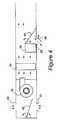
- FIG. 4illustrates an HVAC system air handling section according to one aspect of the present invention.
- a thermal management system, 10for an automotive vehicle includes several air-cooled heat exchangers which are cooled serially by air forced by fan 26 through air intake duct 30 .
- the first heat exchanger receiving outside airis HVAC exchanger 14 .
- Air leaving heat exchanger 14flows through low temperature radiator 18 , which has temperature sensors associated therewith.
- Low temperature exchanger 18is an electronics heat exchanger.
- Air having flowed through heat exchangers 14 and 18then flows through heat exchanger 22 , which is a high temperature radiator with temperature sensors.
- Heat exchanger, 22is a prime mover heat exchanger for cooling an engine, a fuel cell, a battery pack, or other type of prime mover, including prime movers combining various ones of these elements.
- HVAC condenser 14receives compressed refrigerant vapor from AC compressor 50 , which is equipped with associated temperature and pressure sensors (not shown). After the vapor has been changed to a liquid within condenser 14 , the liquid refrigerant flows to AC evaporator 54 . The operation of AC compressor 50 is controlled by climate controller 46 , under commands from vehicle controller 42 . Heat exchanger 18 receives coolant from various electronic components, 64 . Finally, heat exchanger 22 receives heated coolant from prime mover 62 . Prime mover 62 is controlled by prime mover controller 58 , under commands from vehicle controller 42 . Cooling controller 60 operates fan 26 .
- HVAC condenser 14air passing through HVAC condenser 14 is heated before moving serially to the electronics heat exchanger, low temperature radiator 18 .
- the temperature of the flowing airbuilds again as air passes through the prime mover heat exchanger, high temperature radiator 22 .
- itis necessary to reduce the input of heat into the air flowing through HVAC condenser 14 .
- FIG. 2illustrates a method for controlling the heat input into the cooling system through HVAC condenser 14 .
- FIG. 2is a plot showing compressor current for an electrodrive HVAC compressor as a function of two system operating temperatures.
- the control temperaturesmay, for example, be associated with some or all of: prime mover 62 , electronic components 64 , or other operating temperatures which, if uncontrolled, could result in component or system damage or inoperability.
- a control temperaturesuch as an electronic component temperature
- the drive, or control, current of HVAC compressor 50is ramped down to a lower level.
- compressor 50operating at a reduced speed, a lesser amount of heat will be rejected by HVAC condenser 14 , thereby reducing the amount of heating of air flowing subsequently to heat exchangers 18 and 22 .
- Thiswill increase the amount of cooling available to the electronics componentry, as well as to the prime mover.
- the control temperaturecontinues to increase, the current will be ramped down further until a quasi steady state is reached.
- the ramp down illustratedis linear, but could alternatively be a polynomial function.
- FIG. 3illustrates, for a mechanically driven HVAC compressor, a control scheme in which compressor 50 is cycled off based on variable allowable durations for compressor clutch engaged time below a variable control pressure measured at the low pressure portion of the refrigerant loop.
- the variables of allowable duration and control pressureare changed as a function of the status of one or more control temperatures of the thermal management system. Should the pressure ever reach P 1 in this scheme, the clutch is disengaged to prevent the formation of ice on the evaporator.
- P 5is the pressure at which the clutch is engaged. If a control temperature of the thermal management system increases to an extent requiring a compromise with air conditioning performance, then the clutch control pressure P 1 is raised to P 2 .
- the clutchOn the subsequent clutch cycle, the clutch is allowed to stay engaged for a certain time equal to T 3 minus T 2 . Should the control temperature still not be reduced sufficiently, then, on the subsequent clutch cycle, the time duration is reduced to a revised time equal to T 5 minus T 4 , which in this example approaches zero. Should the control temperature still not be reduced sufficiently, then on the subsequent clutch cycle the control pressure is raised to P 3 . Should the control temperature still not be reduced sufficiently, then on the subsequent clutch cycle the control pressure is raised to P 4 . Should the control temperature eventually be reduced sufficiently, then the control pressure is reduced back to P 3 . In other words, operation of compressor 50 will be limited as component temperature increases, so as to control heat rejected through HVAC condenser 14 , so as to result in a balance between compressor run time for passenger cabin comfort and the impact of component temperature upon vehicle mobility.
- FIG. 4illustrates a portion of an HVAC system according to the present invention in which cabin air passes variable recirculation door 66 and enters blower case 68 . Outside air enters through outside air inlet 70 . After passing through blower 74 , the air flows through evaporator core 54 , and then through heater core 78 (both of cores 54 and 78 are also shown in FIG. 1 ). Some of the air flowing through the HVAC system may be allowed by blend door 82 to pass into the passenger cabin, whereas some may be rejected through variable dump door 86 and externally connected duct 88 to the ambient. In this manner, heater core 78 functions as an integral cooling assist system for rejecting heat from the HVAC system directly to the ambient, so as to reduce the temperature of the coolant flowing, for example, to prime mover 62 .
- prime mover 62may be either a battery system, or a fuel cell system, or an internal combustion engine, or a hybrid including an internal combustion engine, batteries, and an electrodrive motor and transmission, or a fuel cell and associated electrodrive motor and transmission device.
- Such combinations of prime mover componentryare known to those skilled in the art; their selection is beyond the scope of the present invention.
Landscapes
- Physics & Mathematics (AREA)
- Thermal Sciences (AREA)
- Engineering & Computer Science (AREA)
- Mechanical Engineering (AREA)
- Air-Conditioning For Vehicles (AREA)
Abstract
Description
Claims (16)
Priority Applications (1)
| Application Number | Priority Date | Filing Date | Title |
|---|---|---|---|
| US11/308,382US7845187B2 (en) | 2006-03-20 | 2006-03-20 | Thermal management system and method for automotive vehicle |
Applications Claiming Priority (1)
| Application Number | Priority Date | Filing Date | Title |
|---|---|---|---|
| US11/308,382US7845187B2 (en) | 2006-03-20 | 2006-03-20 | Thermal management system and method for automotive vehicle |
Publications (2)
| Publication Number | Publication Date |
|---|---|
| US20070214819A1 US20070214819A1 (en) | 2007-09-20 |
| US7845187B2true US7845187B2 (en) | 2010-12-07 |
Family
ID=38516319
Family Applications (1)
| Application Number | Title | Priority Date | Filing Date |
|---|---|---|---|
| US11/308,382Active2029-06-08US7845187B2 (en) | 2006-03-20 | 2006-03-20 | Thermal management system and method for automotive vehicle |
Country Status (1)
| Country | Link |
|---|---|
| US (1) | US7845187B2 (en) |
Cited By (29)
| Publication number | Priority date | Publication date | Assignee | Title |
|---|---|---|---|---|
| US20100206868A1 (en)* | 2007-11-06 | 2010-08-19 | Carrier Corporation | Heat pump with heat recovery |
| US20100300125A1 (en)* | 2009-05-28 | 2010-12-02 | Ford Global Technologies, Llc | Automotive climate system and method of controlling same |
| US20110132030A1 (en)* | 2009-12-03 | 2011-06-09 | Hyundai Motor Company | Integrated Cooling System for Eco-Friendly Vehicle |
| US20130337296A1 (en)* | 2012-06-13 | 2013-12-19 | Ford Global Technologies, Llc | Cooling System Having Active Cabin Venting for a Vehicle Battery |
| US8615371B2 (en) | 2011-04-15 | 2013-12-24 | Thermo King Corporation | Fuel consumption measurement of bus HVAC units |
| USD785771S1 (en) | 2015-05-13 | 2017-05-02 | Dometic Sweden Ab | Air shroud |
| USD785772S1 (en) | 2015-05-13 | 2017-05-02 | Dometic Sweden Ab | Air shroud assembly |
| USD811566S1 (en) | 2016-02-12 | 2018-02-27 | Dometic Sweden Ab | Recreational vehicle air-conditioning unit |
| USD817466S1 (en) | 2016-01-19 | 2018-05-08 | Dometic Sweden Ab | Air shroud assembly |
| US9975405B2 (en) | 2013-03-14 | 2018-05-22 | Dometic Corporation | Modular air grill assembly |
| USD824499S1 (en) | 2016-04-28 | 2018-07-31 | Dometic Sweden Ab | Air-conditioning unit |
| USD850609S1 (en) | 2015-10-15 | 2019-06-04 | Dometic Sweden Ab | Modular air grill |
| US10369887B2 (en)* | 2017-07-21 | 2019-08-06 | Ford Global Technologies, Llc | Inverter system controller power optimization |
| US10547070B2 (en) | 2018-03-09 | 2020-01-28 | Toyota Motor Engineering & Manufacturing North America, Inc. | STL actuation-path planning |
| US10589593B2 (en) | 2016-01-19 | 2020-03-17 | Dometic Sweden Ab | Parking cooler |
| US10590942B2 (en) | 2017-12-08 | 2020-03-17 | Toyota Motor Engineering & Manufacturing North America, Inc. | Interpolation of homotopic operating states |
| US10665875B2 (en) | 2017-12-08 | 2020-05-26 | Toyota Motor Engineering & Manufacturing North America, Inc. | Path control concept |
| US10675941B2 (en) | 2016-02-22 | 2020-06-09 | Dometic Sweden Ab | Air-conditioner control |
| US10714767B2 (en) | 2017-12-07 | 2020-07-14 | Toyota Motor Engineering & Manufacturing North America, Inc. | Fuel cell air system safe operating region |
| USD905217S1 (en) | 2018-09-05 | 2020-12-15 | Dometic Sweden Ab | Air conditioning apparatus |
| US10871519B2 (en) | 2017-11-07 | 2020-12-22 | Toyota Motor Engineering & Manufacturing North America, Inc. | Fuel cell stack prediction utilizing IHOS |
| USD907183S1 (en) | 2016-11-23 | 2021-01-05 | Dometic Sweden Ab | Air conditioning apparatus |
| USD915569S1 (en) | 2017-02-17 | 2021-04-06 | Dometic Sweden Ab | Shroud assembly |
| US10971748B2 (en) | 2017-12-08 | 2021-04-06 | Toyota Motor Engineering & Manufacturing North America, Inc. | Implementation of feedforward and feedback control in state mediator |
| US10985391B2 (en) | 2018-03-06 | 2021-04-20 | Toyota Motor Engineering & Manufacturing North America, Inc. | Real time iterative solution using recursive calculation |
| US11034208B2 (en) | 2016-02-22 | 2021-06-15 | Dometic Sweden Ab | Vehicle air conditioner |
| US11482719B2 (en) | 2017-12-08 | 2022-10-25 | Toyota Jidosha Kabushiki Kaisha | Equation based state estimate for air system controller |
| US11772452B2 (en) | 2017-11-16 | 2023-10-03 | Dometic Sweden Ab | Air conditioning apparatus for recreational vehicles |
| US12043081B2 (en) | 2019-10-17 | 2024-07-23 | Dometic Sweden Ab | Air conditioning apparatus for recreational vehicles |
Families Citing this family (2)
| Publication number | Priority date | Publication date | Assignee | Title |
|---|---|---|---|---|
| CN102144139B (en)* | 2008-02-22 | 2013-06-05 | 陶氏环球技术公司 | Thermal Energy Storage Materials |
| US20250042223A1 (en)* | 2023-08-03 | 2025-02-06 | Hitachi Rail Sts S.P.A. | Electric or hybrid traction vehicle equipped with an air conditioning system, with heat recovery from cooling of electrical and/or electronic components |
Citations (15)
| Publication number | Priority date | Publication date | Assignee | Title |
|---|---|---|---|---|
| US5609037A (en)* | 1994-11-15 | 1997-03-11 | Fischler; Richard | Self-contained vehicle refrigeration unit |
| US5983658A (en) | 1997-05-12 | 1999-11-16 | Ford Motor Company | Automotive air conditioning |
| US20020073726A1 (en)* | 2000-12-20 | 2002-06-20 | Honda Giken Kogyo Kabushiki Kaisha | Cooling apparatus of hybrid vehicle, including serially-connected cooling systems for electric devices which have different heat resisting allowable temperatures |
| US6450275B1 (en)* | 2000-11-02 | 2002-09-17 | Ford Motor Company | Power electronics cooling for a hybrid electric vehicle |
| US6598671B1 (en) | 1999-12-29 | 2003-07-29 | General Motors Corporation | Hybrid heating system and method for vehicles |
| US6651761B1 (en)* | 2001-09-27 | 2003-11-25 | Ford Global Technologies, Llc | Temperature control system for fuel cell electric vehicle cooling circuit |
| US6675873B2 (en) | 2001-07-12 | 2004-01-13 | Denso Corporation | Automotive air-conditioner having electric heater and electrically driven compressor |
| US6675592B2 (en) | 2002-02-02 | 2004-01-13 | Visteon Global Technologies, Inc. | Electronic control strategy for A/C compressor |
| US20040118142A1 (en) | 2002-12-20 | 2004-06-24 | Hsu John Sheungchun | Methods and apparatus for thermal management of vehicle systems and components |
| US6755032B1 (en) | 2000-01-13 | 2004-06-29 | Ford Global Technologies, Inc. | Control method for a vehicle having an engine and an accessory device |
| US20040200610A1 (en) | 2003-01-15 | 2004-10-14 | Calsonic Kansei Corporation | Air conditioning apparatus for vehicle |
| US20050044873A1 (en) | 2003-08-28 | 2005-03-03 | Goro Tamai | Climate cooling control systems and methods for hybrid vehicles |
| US20050077367A1 (en) | 2003-10-11 | 2005-04-14 | Dae Woo Lee | Vehicle heater control apparatus and method for controlling the same |
| US6978628B2 (en)* | 2002-12-26 | 2005-12-27 | Denso Corporation | Air conditioning device for vehicle |
| US7310961B2 (en)* | 2004-06-16 | 2007-12-25 | Toyota Jidosha Kabushiki Kaisha | Heat exchange apparatus and hybrid vehicle including heat exchange apparatus |
- 2006
- 2006-03-20USUS11/308,382patent/US7845187B2/enactiveActive
Patent Citations (15)
| Publication number | Priority date | Publication date | Assignee | Title |
|---|---|---|---|---|
| US5609037A (en)* | 1994-11-15 | 1997-03-11 | Fischler; Richard | Self-contained vehicle refrigeration unit |
| US5983658A (en) | 1997-05-12 | 1999-11-16 | Ford Motor Company | Automotive air conditioning |
| US6598671B1 (en) | 1999-12-29 | 2003-07-29 | General Motors Corporation | Hybrid heating system and method for vehicles |
| US6755032B1 (en) | 2000-01-13 | 2004-06-29 | Ford Global Technologies, Inc. | Control method for a vehicle having an engine and an accessory device |
| US6450275B1 (en)* | 2000-11-02 | 2002-09-17 | Ford Motor Company | Power electronics cooling for a hybrid electric vehicle |
| US20020073726A1 (en)* | 2000-12-20 | 2002-06-20 | Honda Giken Kogyo Kabushiki Kaisha | Cooling apparatus of hybrid vehicle, including serially-connected cooling systems for electric devices which have different heat resisting allowable temperatures |
| US6675873B2 (en) | 2001-07-12 | 2004-01-13 | Denso Corporation | Automotive air-conditioner having electric heater and electrically driven compressor |
| US6651761B1 (en)* | 2001-09-27 | 2003-11-25 | Ford Global Technologies, Llc | Temperature control system for fuel cell electric vehicle cooling circuit |
| US6675592B2 (en) | 2002-02-02 | 2004-01-13 | Visteon Global Technologies, Inc. | Electronic control strategy for A/C compressor |
| US20040118142A1 (en) | 2002-12-20 | 2004-06-24 | Hsu John Sheungchun | Methods and apparatus for thermal management of vehicle systems and components |
| US6978628B2 (en)* | 2002-12-26 | 2005-12-27 | Denso Corporation | Air conditioning device for vehicle |
| US20040200610A1 (en) | 2003-01-15 | 2004-10-14 | Calsonic Kansei Corporation | Air conditioning apparatus for vehicle |
| US20050044873A1 (en) | 2003-08-28 | 2005-03-03 | Goro Tamai | Climate cooling control systems and methods for hybrid vehicles |
| US20050077367A1 (en) | 2003-10-11 | 2005-04-14 | Dae Woo Lee | Vehicle heater control apparatus and method for controlling the same |
| US7310961B2 (en)* | 2004-06-16 | 2007-12-25 | Toyota Jidosha Kabushiki Kaisha | Heat exchange apparatus and hybrid vehicle including heat exchange apparatus |
Cited By (43)
| Publication number | Priority date | Publication date | Assignee | Title |
|---|---|---|---|---|
| US8373099B2 (en)* | 2007-11-06 | 2013-02-12 | Carrier Corporation | Heat pump with heat recovery |
| US20100206868A1 (en)* | 2007-11-06 | 2010-08-19 | Carrier Corporation | Heat pump with heat recovery |
| US20100300125A1 (en)* | 2009-05-28 | 2010-12-02 | Ford Global Technologies, Llc | Automotive climate system and method of controlling same |
| US8015833B2 (en)* | 2009-05-28 | 2011-09-13 | Ford Global Technologies, Llc | Automotive climate system and method of controlling same |
| US9180753B2 (en)* | 2009-12-03 | 2015-11-10 | Hyundai Motor Company | Integrated cooling system for eco-friendly vehicle |
| US20110132030A1 (en)* | 2009-12-03 | 2011-06-09 | Hyundai Motor Company | Integrated Cooling System for Eco-Friendly Vehicle |
| US9815349B2 (en) | 2009-12-03 | 2017-11-14 | Hyundai Motor Company | Integrated cooling system for eco-friendly vehicle |
| US8615371B2 (en) | 2011-04-15 | 2013-12-24 | Thermo King Corporation | Fuel consumption measurement of bus HVAC units |
| US10744901B2 (en)* | 2012-06-13 | 2020-08-18 | Ford Global Technologies, Llc | Cooling system having active cabin venting for a vehicle battery |
| US20130337296A1 (en)* | 2012-06-13 | 2013-12-19 | Ford Global Technologies, Llc | Cooling System Having Active Cabin Venting for a Vehicle Battery |
| US9975405B2 (en) | 2013-03-14 | 2018-05-22 | Dometic Corporation | Modular air grill assembly |
| USD785771S1 (en) | 2015-05-13 | 2017-05-02 | Dometic Sweden Ab | Air shroud |
| USD785772S1 (en) | 2015-05-13 | 2017-05-02 | Dometic Sweden Ab | Air shroud assembly |
| USD850609S1 (en) | 2015-10-15 | 2019-06-04 | Dometic Sweden Ab | Modular air grill |
| USD884870S1 (en) | 2015-10-15 | 2020-05-19 | Dometic Sweden Ab | Modular air grill |
| US10589593B2 (en) | 2016-01-19 | 2020-03-17 | Dometic Sweden Ab | Parking cooler |
| US12049120B2 (en) | 2016-01-19 | 2024-07-30 | Dometic Sweden Ab | Parking cooler |
| USD862668S1 (en) | 2016-01-19 | 2019-10-08 | Dometic Sweden Ab | Air shroud assembly |
| USD865926S1 (en) | 2016-01-19 | 2019-11-05 | Dometic Sweden Ab | Air shroud assembly |
| US11613157B2 (en) | 2016-01-19 | 2023-03-28 | Dometic Sweden Ab | Parking cooler |
| USD817466S1 (en) | 2016-01-19 | 2018-05-08 | Dometic Sweden Ab | Air shroud assembly |
| USD811566S1 (en) | 2016-02-12 | 2018-02-27 | Dometic Sweden Ab | Recreational vehicle air-conditioning unit |
| US11560036B2 (en) | 2016-02-22 | 2023-01-24 | Dometic Sweden Ab | Frame fitting arrangement for vehicle air conditioner |
| US11472256B2 (en) | 2016-02-22 | 2022-10-18 | Dometic Sweden Ab | Air-conditioner control |
| US10675941B2 (en) | 2016-02-22 | 2020-06-09 | Dometic Sweden Ab | Air-conditioner control |
| US11034208B2 (en) | 2016-02-22 | 2021-06-15 | Dometic Sweden Ab | Vehicle air conditioner |
| USD841138S1 (en) | 2016-04-28 | 2019-02-19 | Dometic Sweden Ab | Air-conditioning unit |
| USD824499S1 (en) | 2016-04-28 | 2018-07-31 | Dometic Sweden Ab | Air-conditioning unit |
| USD907183S1 (en) | 2016-11-23 | 2021-01-05 | Dometic Sweden Ab | Air conditioning apparatus |
| USD915569S1 (en) | 2017-02-17 | 2021-04-06 | Dometic Sweden Ab | Shroud assembly |
| US10369887B2 (en)* | 2017-07-21 | 2019-08-06 | Ford Global Technologies, Llc | Inverter system controller power optimization |
| US10871519B2 (en) | 2017-11-07 | 2020-12-22 | Toyota Motor Engineering & Manufacturing North America, Inc. | Fuel cell stack prediction utilizing IHOS |
| US11772452B2 (en) | 2017-11-16 | 2023-10-03 | Dometic Sweden Ab | Air conditioning apparatus for recreational vehicles |
| US10714767B2 (en) | 2017-12-07 | 2020-07-14 | Toyota Motor Engineering & Manufacturing North America, Inc. | Fuel cell air system safe operating region |
| US10590942B2 (en) | 2017-12-08 | 2020-03-17 | Toyota Motor Engineering & Manufacturing North America, Inc. | Interpolation of homotopic operating states |
| US10665875B2 (en) | 2017-12-08 | 2020-05-26 | Toyota Motor Engineering & Manufacturing North America, Inc. | Path control concept |
| US11482719B2 (en) | 2017-12-08 | 2022-10-25 | Toyota Jidosha Kabushiki Kaisha | Equation based state estimate for air system controller |
| US10971748B2 (en) | 2017-12-08 | 2021-04-06 | Toyota Motor Engineering & Manufacturing North America, Inc. | Implementation of feedforward and feedback control in state mediator |
| US10985391B2 (en) | 2018-03-06 | 2021-04-20 | Toyota Motor Engineering & Manufacturing North America, Inc. | Real time iterative solution using recursive calculation |
| US10547070B2 (en) | 2018-03-09 | 2020-01-28 | Toyota Motor Engineering & Manufacturing North America, Inc. | STL actuation-path planning |
| USD944374S1 (en) | 2018-09-05 | 2022-02-22 | Dometic Sweden Ab | Air conditioning apparatus |
| USD905217S1 (en) | 2018-09-05 | 2020-12-15 | Dometic Sweden Ab | Air conditioning apparatus |
| US12043081B2 (en) | 2019-10-17 | 2024-07-23 | Dometic Sweden Ab | Air conditioning apparatus for recreational vehicles |
Also Published As
| Publication number | Publication date |
|---|---|
| US20070214819A1 (en) | 2007-09-20 |
Similar Documents
| Publication | Publication Date | Title |
|---|---|---|
| US7845187B2 (en) | Thermal management system and method for automotive vehicle | |
| US11407275B2 (en) | Heat flow management device and method for operating a heat flow management device | |
| US11325445B2 (en) | Thermal management system for vehicle | |
| CN101551174B (en) | Vehicle hvac and battery thermal management | |
| US8215432B2 (en) | Battery thermal system for vehicle | |
| CN102275521B (en) | Thermal management system with dual mode coolant loops | |
| US9827846B2 (en) | Traction battery cooling system | |
| US20130269911A1 (en) | Thermal management system and related methods for vehicle having electric traction motor and range extending device | |
| CN102442219B (en) | Thermal management controls for a vehicle having a rechargeable energy storage system | |
| US11541725B2 (en) | Thermal management system and integrated thermal management module for vehicle | |
| US20080034767A1 (en) | Methods of Optimizing Vehicular Air Conditioning Control Systems | |
| CN109941117B (en) | Electric vehicle | |
| US20140338376A1 (en) | Thermal management system for vehicle having traction motor | |
| US20090249807A1 (en) | HVAC and Battery Thermal Management for a Vehicle | |
| US20120297809A1 (en) | Refrigerant loop for battery electric vehicle with internal heat exchanger for heat exchange with coolant | |
| JP2011068348A (en) | Vehicle inside temperature control method of electric motor vehicle and air-conditioning system | |
| CN113752779B (en) | Thermal system control of a vehicle | |
| US12365221B2 (en) | Vehicle HVAC system | |
| US20220410663A1 (en) | Thermal management system control method for vehicle | |
| CN105172522A (en) | Thermal management system of hybrid vehicle | |
| KR20220022536A (en) | Thermal management system for electric vehicle | |
| US20220194163A1 (en) | Integrated thermal management system for mobility vehicles | |
| US12358337B2 (en) | Electric vehicle thermal management system and vehicle | |
| CN116278582A (en) | Carriage comfort management system | |
| US20150114018A1 (en) | Viscous heater for heat pump system |
Legal Events
| Date | Code | Title | Description |
|---|---|---|---|
| AS | Assignment | Owner name:FORD MOTOR COMPANY, MICHIGAN Free format text:ASSIGNMENT OF ASSIGNORS INTEREST;ASSIGNORS:PATEL, UPENDRA J.;SCHWARTZ, WILLIAM;REEL/FRAME:017333/0855 Effective date:20060316 | |
| AS | Assignment | Owner name:FORD GLOBAL TECHNOLOGIES, LLC, MICHIGAN Free format text:ASSIGNMENT OF ASSIGNORS INTEREST;ASSIGNOR:FORD MOTOR COMPANY;REEL/FRAME:017392/0247 Effective date:20060320 | |
| FEPP | Fee payment procedure | Free format text:PAYOR NUMBER ASSIGNED (ORIGINAL EVENT CODE: ASPN); ENTITY STATUS OF PATENT OWNER: LARGE ENTITY | |
| STCF | Information on status: patent grant | Free format text:PATENTED CASE | |
| FPAY | Fee payment | Year of fee payment:4 | |
| MAFP | Maintenance fee payment | Free format text:PAYMENT OF MAINTENANCE FEE, 8TH YEAR, LARGE ENTITY (ORIGINAL EVENT CODE: M1552) Year of fee payment:8 | |
| MAFP | Maintenance fee payment | Free format text:PAYMENT OF MAINTENANCE FEE, 12TH YEAR, LARGE ENTITY (ORIGINAL EVENT CODE: M1553); ENTITY STATUS OF PATENT OWNER: LARGE ENTITY Year of fee payment:12 |