US7844766B1 - System and method for location specific computer enabled services/monitoring - Google Patents
System and method for location specific computer enabled services/monitoringDownload PDFInfo
- Publication number
- US7844766B1 US7844766B1US12/245,234US24523408AUS7844766B1US 7844766 B1US7844766 B1US 7844766B1US 24523408 AUS24523408 AUS 24523408AUS 7844766 B1US7844766 B1US 7844766B1
- Authority
- US
- United States
- Prior art keywords
- hot
- server
- electronic
- location
- swappable
- Prior art date
- Legal status (The legal status is an assumption and is not a legal conclusion. Google has not performed a legal analysis and makes no representation as to the accuracy of the status listed.)
- Expired - Fee Related, expires
Links
Images


Classifications
- H—ELECTRICITY
- H04—ELECTRIC COMMUNICATION TECHNIQUE
- H04L—TRANSMISSION OF DIGITAL INFORMATION, e.g. TELEGRAPHIC COMMUNICATION
- H04L41/00—Arrangements for maintenance, administration or management of data switching networks, e.g. of packet switching networks
- H04L41/08—Configuration management of networks or network elements
- H04L41/0803—Configuration setting
- H04L41/0813—Configuration setting characterised by the conditions triggering a change of settings
- H04L41/0816—Configuration setting characterised by the conditions triggering a change of settings the condition being an adaptation, e.g. in response to network events
- G—PHYSICS
- G06—COMPUTING OR CALCULATING; COUNTING
- G06F—ELECTRIC DIGITAL DATA PROCESSING
- G06F9/00—Arrangements for program control, e.g. control units
- G06F9/06—Arrangements for program control, e.g. control units using stored programs, i.e. using an internal store of processing equipment to receive or retain programs
- G06F9/44—Arrangements for executing specific programs
- G06F9/4401—Bootstrapping
- G06F9/4416—Network booting; Remote initial program loading [RIPL]
- H—ELECTRICITY
- H04—ELECTRIC COMMUNICATION TECHNIQUE
- H04L—TRANSMISSION OF DIGITAL INFORMATION, e.g. TELEGRAPHIC COMMUNICATION
- H04L41/00—Arrangements for maintenance, administration or management of data switching networks, e.g. of packet switching networks
- H04L41/50—Network service management, e.g. ensuring proper service fulfilment according to agreements
- H04L41/5041—Network service management, e.g. ensuring proper service fulfilment according to agreements characterised by the time relationship between creation and deployment of a service
- H04L41/5054—Automatic deployment of services triggered by the service manager, e.g. service implementation by automatic configuration of network components
Definitions
- the system and method of the present embodimentrelate generally to centralized control of a network infrastructure for a building. What is needed are a system and method for providing location-specific computer enabled services and monitoring, and having minimally invasive reconfiguration and replacement.
- the method of the present embodiment for providing location-specific computer enabled services/monitoring, having minimally invasive reconfiguration/replacementcan include, but is not limited to including, the steps of providing a first relationship between a location and electronic configuration information, providing a second relationship between the location and an electronic identifier, providing, at the location, an electronic service connecting/monitoring component, the electronic service connecting/monitoring component comprising an electronic component having the electronic identifier embodied therein, and a readable component providing the electronic identifier in a electronically readable format, accessing the electronic identifier from the readable component, accessing the location associated with the accessed electronic identifier according to the second relationship, accessing the electronic configuration information associated with the associated location according to the first relationship, loading the associated electronic configuration information onto the service connecting/monitoring component, and enabling modification of the associated electronic configuration information to reconfigure based on the location.
- the system of the present embodiment for providing location-specific computer enabled services/monitoring, having minimally invasive reconfiguration/replacementcan include, but is not limited to including, a relationship provider enabling a first relationship between a location and electronic configuration information and a second relationship between the location and an electronic identifier, an electronic service connecting/monitoring component at the location including an electronic component having the electronic identifier embodied therein, and a readable component providing the electronic identifier in an electronically readable format, an accessor accessing the electronic identifier from the readable component, accessing the location associated with the accessed the electronic identifier according to the second relationship, and accessing the electronic configuration information associated with the associated location according to the first relationship, and a server loading the associated the electronic configuration information onto the service connecting/monitoring component and enabling modification of the associated the electronic configuration information to reconfigure based on the location.
- FIG. 4is a flowchart of the method of the present teachings.
- Service connect/monitor component 11can be installed at location 15 , and first relationship 23 can be established between location 15 and configuration information 17 . Second relationship 21 can be established between location 15 and readable component 27 .
- Server 19can include, but is not limited to including, management node 49 , relationship processor 48 , and business rules 47 . Server 19 and service connect/monitor component 11 can communicate through port 53 . Other systems 43 can provide data to management node 49 that could assist in the centralized management of service connect/monitor component 11 . There may be any number of service connect/monitor components 11 all managed by server 19 . Power 31 may be supplied, for example, locally, centralized, or in line, to service connect/monitor component(s) 11 .
- Relationship provider 48can enable first relationship 23 between location 15 and electronic configuration information 17 and second relationship 21 between location 15 and an electronic identifier 13 .
- Electronic service connecting/monitoring component 11 at location 15can include electronic component 25 having electronic identifier 13 embodied therein, and readable component 27 providing electronic identifier 13 in an electronically readable format.
- Accessor 14can access electronic identifier 13 from readable component 27 , and can access location 15 associated with accessed electronic identifier 13 according to second relationship 21 , and can access electronic configuration information 17 associated with associated location 15 according to first relationship 23 .
- Server 19can load associated electronic configuration information 17 onto service connecting/monitoring component 11 and enable modification of associated electronic configuration information 17 to reconfigure location 15 .
- service connecting/monitoring component 11can be configured as daughter card 61 ( FIG. 2 ) having connection components 29 and power connectors 31 .
- Electronic component 25can be configured as hot-swappable board 65 ( FIG. 2 ).
- Hot-swappable board 65( FIG. 2 ) can receive power through power connection 31 from daughter card 61 ( FIG. 2 ), and can include processor 35 and computer readable memory 37 having computer readable code 39 embodied therein.
- Hot-swappable board 65 ( FIG. 2 )can access electronic configuration information 17 associated with location 15 and loading electronic configuration information 17 .
- Server 19can provide first relationship 23 and second relationship 21 .
- Daughter card 61( FIG. 2 ) having connection components 29 and power connectors 31 .
- Electronic component 25can be configured as hot-swappable board 65 ( FIG. 2 ).
- Hot-swappable board 65( FIG. 2 ) can receive power through power connection 31 from daughter card 61 ( FIG. 2 ), and can include processor 35 and computer readable memory 37 having
- Server 19can configure location 15 by downloading associated electronic configuration information 17 to hot-swappable board 65 ( FIG. 2 ), and enable real time communications between server 19 and hot-swappable board 65 ( FIG. 2 ).
- Power connection 31can be a centralized power supply.
- Server 19can be integrated with other systems 43 to provide alerts 45 based on business rules 47 .
- Server 19can detects events in hot-swappable board 65 ( FIG. 2 ) by using business rules 47 , and can receive changes 58 to business rules 47 from other systems 43 .
- Server 19can configure port 53 between server 19 and hot-swappable board 65 ( FIG. 2 ) and can configure management node 49 .
- service connecting/monitoring component 11can include components for requesting a temporary IP address for hot-swappable board 65 , receiving the temporary IP address, assigning a management VLAN for management communications, receiving a management node IP address to communicate with management node 49 ( FIG. 1 ), and requesting a boot script 67 from management node 49 ( FIG. 1 ) using the management node IP address and the management VLAN.
- Service connecting/monitoring component 11FIG.
- Service connecting/monitoring component 11can still further include components for loading boot image 71 and application disk image 73 into memory 37 ( FIG. 1 ) of hot-swappable board 65 , retrieving daughter card unique identifier 13 ( FIG.
- the identification chipsuch as, for example, DALLAS SEMICONDUCTOR® DS2401, on the daughter card 61 can act as a media access controller (MAC) address or localized unique identifier (UID).
- Configuration informationcan be downloaded from server 19 via, for example, a serial identification chip of the daughter card 61 that can identify the hot-swappable board 65 .
- the hot-swappable board 65can be swapped out for a new hot-swappable board 65 , which can reduce maintenance costs. The connections remain in place, so there is no chance of incorrect wiring.
- a fiber interfacemay be included, and power may be hot swapped.
- there is an initial configuration for deploymentwhich can be retrieved.
- the configurationcan be maintain and monitored, and the system can include a network operations center (NOC) 81 ( FIG. 2 ) which can be used for trouble identification and resolution. Monitoring can be proactive in the form of alarms and alerts.
- NOCnetwork operations center
- the hotswap processcan be followed by a self-healing process. If a new hot-swappable board is supplied, it can automatically continue processing at the point at which the failed hot-swappable board ceased operations because management node 49 can stored configuration information 17 ( FIG. 1 ). Because unique identifier 13 ( FIG. 1 ) does not change when hot-swappable board 65 is replaced, management node 49 realizes that it is communicating with a replacement device.
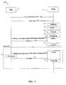
- method 150can include, but is not limited to including, the steps of initiating 151 , by electronic service connecting/monitoring component 11 ( FIG. 1 ) such as, for example, Hospitality Access Point/ROOM CENTER® (HAP/RC), available from LORICA SOLUTIONS®, a web boot request to server 19 ( FIG. 1 ) which returns 153 boot script 67 to electronic service connecting/monitoring component 11 ( FIG. 1 ) which processes 155 boot script 67 ( FIG. 2 ), boots 157 processor 35 ( FIG. 1 ), runs 159 a customized script such as, for example, a room center script, and runs 161 a dhcpcd-up script.
- electronic service connecting/monitoring component 11such as, for example, Hospitality Access Point/ROOM CENTER® (HAP/RC), available from LORICA SOLUTIONS®
- server 19FIG. 1
- returns 153 boot script 67to electronic service connecting/monitoring component 11 ( FIG. 1 ) which processes 155 boot script 67 ( FIG
- method 200 for providing location-specific computer enabled services/monitoring, having minimally invasive reconfiguration/replacementcan include, but is not limited to including, the steps of providing 201 first relationship 23 ( FIG. 1 ) between location 15 ( FIG. 1 ) and electronic configuration information 17 ( FIG. 1 ), providing 203 second relationship 21 ( FIG. 1 ) between location 15 ( FIG. 1 ) and electronic identifier 13 ( FIG. 1 ), and providing 205 , at location 15 ( FIG. 1 ), electronic service connecting/monitoring component 11 ( FIG. 1 ).
- Electronic service connecting/monitoring component 11 ( FIG. 1 )can include, but is not limited to including, electronic component 25 ( FIG. 1 ) having electronic identifier 13 ( FIG.
- Method 150can further include the steps of accessing 207 electronic identifier 13 ( FIG. 1 ) from readable component 27 ( FIG. 1 ), accessing 209 location 15 ( FIG. 1 ) associated with accessed electronic identifier 13 ( FIG. 1 ) according to the second relationship 21 ( FIG. 1 ), accessing 211 electronic configuration information 17 ( FIG. 1 ) associated with associated location 15 ( FIG. 1 ) according to the first relationship 23 ( FIG. 1 ), loading 213 associated electronic configuration information 17 ( FIG. 1 ) onto service connecting/monitoring component 11 ( FIG.
- Method 200can also include the steps of configuring service connecting/monitoring component 11 ( FIG. 1 ) as daughter card 61 ( FIG. 2 ) having connection components 29 ( FIG. 1 ) and power connectors 31 ( FIG. 1 ) and configuring electronic component 25 ( FIG. 1 ) as hot-swappable board 65 ( FIG. 2 ).
- Hot-swappable board 65 ( FIG. 2 )can receive power from daughter card 61 ( FIG. 2 ), and can include, but is not limited to including, processor 35 ( FIG. 1 ) and computer readable memory 37 ( FIG. 1 ) having computer readable code 39 ( FIG.
- Hot-swappable board 65can execute the steps of accessing electronic configuration information 17 ( FIG. 1 ) associated with location 15 ( FIG. 1 ) and loading electronic configuration information 17 ( FIG. 1 ).
- Method 200can also include the step of configuring server 19 ( FIG. 1 ) to provide first relationship 23 ( FIG. 1 ) and second relationship 21 ( FIG. 1 ).
- method 200can further include the steps of installing the daughter card 61 ( FIG. 2 ) at location 15 ( FIG. 1 ), providing power connection 31 ( FIG. 1 ) to daughter card 61 ( FIG. 2 ), interconnecting daughter card 61 ( FIG. 2 ) and server 19 ( FIG. 1 ), installing hot-swappable board 65 ( FIG. 2 ), detecting a failure in hot-swappable board 65 ( FIG. 2 ), replacing the failing hot-swappable board with a new hot-swappable board, and configuring location 15 ( FIG. 1 ) by downloading associated electronic configuration information 17 ( FIG. 1 ) to the new hot-swappable board.
- the step of providing power to daughter card 61can include, but is not limited to including, the steps of configuring power connection 31 ( FIG. 1 ) as a central power supply, and interconnecting daughter card 61 ( FIG. 2 ) to the central power supply.
- Method 200can further include the steps of configuring power connection 31 ( FIG. 1 ), for example, but not limited to, local, central, or in line, configuring server 19 ( FIG. 1 ), building configuration information 17 ( FIG. 1 ) on server 19 ( FIG. 1 ), configuring service connecting/monitoring component 11 ( FIG. 1 ) as daughter card 61 ( FIG. 2 ), connecting daughter card 61 ( FIG. 2 ) to power connection 31 ( FIG. 1 ) and to server 19 ( FIG.
- hot-swappable board 65having processor 35 ( FIG. 1 ) and boot loader 41 ( FIG. 1 ), receiving, in processor 35 ( FIG. 1 ) by boot loader 41 ( FIG. 1 ), boot information 55 ( FIG. 2 ) from server 19 ( FIG. 1 ), executing, in processor 35 ( FIG. 1 ), boot information 55 ( FIG. 2 ) to load operating system 57 ( FIG. 1 ) from server 19 ( FIG. 1 ) to processor 35 ( FIG. 1 ), and executing operating system 57 ( FIG. 1 ) to load associated electronic configuration information 17 ( FIG. 1 ).
- method 200can further include the optional steps of enabling real time communications between server 19 ( FIG. 1 ) and hot-swappable board 65 ( FIG. 2 ), integrating server 19 ( FIG. 1 ) with other systems 43 ( FIG. 1 ) to provide alerts 45 ( FIG. 1 ) based on business rules 47 ( FIG. 1 ), detecting events in hot-swappable board 65 ( FIG. 2 ) by using business rules 47 ( FIG. 1 ), receiving changes 58 ( FIG. 1 ) to business rules 47 ( FIG. 1 ) from other systems 43 ( FIG. 1 ), configuring port 53 ( FIG. 1 ) between server 19 ( FIG. 1 ) and hot-swappable board 65 ( FIG.
- the step of executing boot information 55can include, but is not limited to including, the steps of requesting a temporary IP address for hot-swappable board 65 ( FIG. 2 ), receiving the temporary IP address, assigning the management VLAN for management communications, receiving a management node IP address to communicate with management node 49 ( FIG. 1 ), requesting boot script 67 ( FIG. 2 ) from management node 49 ( FIG. 1 ) using the management node IP address and the management VLAN, choosing, at management node 49 ( FIG. 1 ), boot script 67 ( FIG.
- FIG. 2a required action for hot-swappable board 65 ( FIG. 2 ), downloading, using boot script 67 ( FIG. 2 ), boot image 71 ( FIG. 2 ) to hot-swappable board 65 ( FIG. 2 ), downloading, using boot script 67 ( FIG. 2 ), application disk image 73 ( FIG. 2 ) to hot-swappable board 65 ( FIG. 2 ), providing the management VLAN and an address of management node 49 ( FIG. 1 ) to boot image 71 ( FIG. 2 ), booting, from boot script 67 ( FIG. 2 ), boot image 71 ( FIG. 2 ), loading boot image 71 ( FIG. 2 ) and application disk image 73 ( FIG. 2 ) into memory 37 ( FIG.
- the actioncan be, for example, but not limited to, upgrading, testing, and booting.
- the step of executing operating system 57can include, but is not limited to including, the steps of retrieving the IP address associated with electronic identifier 13 ( FIG. 1 ) and the management node IP address, translating electronic configuration information 17 ( FIG. 1 ) to configuration commands, setting hot-swappable board 65 ( FIG.
- the step of translating electronic configuration information 17 ( FIG. 1 )can include, but is not limited to including, the steps of receiving electronic configuration information 17 ( FIG. 1 ) in XML format from server 19 ( FIG. 1 ), and executing code, for example, but not limited to, a PHP script, on hot-swappable board 65 ( FIG. 2 ) to parse electronic configuration information 17 ( FIG.
- the step of transitioning from the configuration modecan include, but is not limited to including, the steps of executing the configuration batch file to configure hot-swappable board 65 , and reporting the status to server 19 ( FIG. 1 ).
- the step of reportingcan include, but is not limited to including, the steps of maintaining an event log, reporting the status in real time, providing the event log to the management node, and reporting the status periodically.
- An exemplary configuration processcan include the steps of building a configuration in a database or by use of an XML file, inserting hot-swappable board 65 ( FIG. 2 ) into daughter card 61 ( FIG. 2 ), and configuring a port as, for example, but not limited to, an IEEE standard 802.1x virtual local area network (VLAN) trunk with a management VLAN for management.
- a resident bootloadercan make a Dynamic Host Configuration Protocol (DHCP) request on the management VLAN, DHCP provides the daughter card internet protocol (IP) address, DHCP provides the management VLAN, and DHCP provides address of management node 49 ( FIG. 1 ).
- the resident bootloadercan be configured to support load or boot script 67 ( FIG.
- phase twocan include retrieving, by operating system 57 ( FIG. 1 ) from management node 49 ( FIG. 1 ), the applications and other information needed to perform specific tasks.
- HTTPhypertext transfer protocol
- the resident bootloadercan request boot script 67 ( FIG. 2 ) from management node 49 ( FIG. 1 ), management node 49 ( FIG.
- Boot script 67( FIG. 2 ) can use a computer scripting language page such as, for example, personal home page (PHP) or active server page (ASP) to determine required script.
- Boot script 67( FIG. 2 ) could be, for example, but not limited to, for firmware upgrading, testing, and/or booting.
- Boot script 67 ( FIG. 2 )can download via boot image 71 ( FIG. 2 ) such as, for example, HTTP zImage.gz Linux boot image, or script downloads via, for example, HTTP Ramdisk.gz application disk image.
- Boot script 67 ( FIG. 2 )can execute from a kernel image to bootstrap operating system 57 ( FIG. 1 ), for example, the LINUX® operating system.
- the management VLAN and an IP addresscan be passed in as kernel parameters.
- Operating system 57 ( FIG. 1 ) and application disk image 73 ( FIG. 2 )can be loaded, and, at the application level, and operating system 57 ( FIG. 1 ) can retrieve the daughter card MAC to use as identifier 13 ( FIG. 1 ).
- identifier 13 ( FIG. 1 )can be used as a masqueraded MAC for the DHCP request so as to retain a static IP.
- An Ethernet interfacecan be configured for the management VLAN for management node 49 ( FIG. 1 ).
- the management VLANcan be separated from the rest of the network and can be discovered by the hot-swappable board 65 ( FIG. 2 ). In this process, DHCP operates at operating system level booting to retrieve the IP address of management node 49 ( FIG.
- the hot-swappable board 65can download special software in addition to operating system 57 ( FIG. 1 ), for example, boot bundle.gz, to retrieve scripts and files the can control the next steps.
- the special softwarecan be customized according to electronic identification 13 ( FIG. 1 ).
- the downloadcan be controlled by, for example, but not limited to, PHP or ASP 79 ( FIG. 2 ) on management node 49 ( FIG. 1 ), and can be tailored based on the MAC and/or identifier 13 ( FIG. 1 ) sent to management node 49 ( FIG. 1 ).
- behaviorcan be changed based on business rules 47 ( FIG. 1 ) accessible within management node 49 ( FIG.
- Business rules 47can include, but are not limited to including, test, location, and product type rules.
- a configuration filesuch as, for example, config.xml
- the configuration filecan be translated to configuration commands which can then be executed to configure status reporting to management node 49 and periodic heartbeat, both in real-time.
- a logcan be maintained, and web services can be provided.
- hot-swappable board 65FIG. 2
- monitors hot-swappable board 65FIG. 2
- configurable business rules 47FIG. 1
- a web servicesuch as XML web service
- System 100FIG. 1
- System 100can be integrated with other systems 43 ( FIG. 1 ) such as, for example, property management systems, that can track whether or not, for example, but not limited to, a hotel room is occupied.
- an immediate alert 45( FIG. 1 ) can be raised; otherwise, a non-immediate alert 45 ( FIG. 1 ) can be raised.
- Business rules 47( FIG. 1 ) can automatically be modified by other systems 43 ( FIG. 1 ) in communications network 59 ( FIG. 1 ).
- an embodiment of system 100can include a structured wire panel, which contains connections for daughter card 61 ( FIG. 2 ), and in which daughter card 61 ( FIG. 2 ) is installed before the electronics are in place, to allow for standalone testing of the wiring.
- a databasecan be built that has unique identifiers 13 ( FIG. 1 ) and associated configuration information 17 ( FIG. 1 ). The unique identifier 13 ( FIG. 1 ), room number, and configuration information 17 ( FIG. 1 ) are eventually correlated by system 100 ( FIG. 1 ).
- Daughter card 61 ( FIG. 2 ) and hot-swappable card 65FIG.
- Hot-swappable board 65( FIG. 2 )
- server 19( FIG. 1 ) that can be set up and monitored and can connect, for example, to the internet, and can become a NOC 81 ( FIG. 1 ) that can maintain a system of room centers.
- Hot-swappable board 65( FIG. 2 ) is installed, its unique identifier 13 ( FIG. 1 ) is read and transferred to a database that contains information about the system of room centers keyed by unique identifiers 13 ( FIG. 1 ).
- Hot-swappable board 65( FIG. 2 ), after installed in daughter card 61 ( FIG. 2 ), uses its identification to build configuration file 18 ( FIG. 1 ) and to configure itself.
- the DHCP protocolcan be used to provide unique identifier 13 ( FIG. 1 ), and HTTP can be used to provide the required handshaking.
- Boot script 67FIG. 2
- operating system 57FIG. 1
- hot-swappable board 65FIG. 2
- processor 35FIG. 1
- power connection 31FIG. 1
- memory 37FIG. 1
- power connection 31can be a 48-Volt power supply that can be connected to daughter card 61 ( FIG. 2 ), and can be a central power supply that supplies power to a number of electronic service connecting/monitoring components 11 ( FIG. 1 ), or a local power supply.
- Power connections 31can be strategically located throughout the building in order to provide centralized or local power, where appropriate.
- methods 150 ( FIG. 3 ), and 200 ( FIG. 4 ) of the present embodimentcan be, in whole or in part, implemented electronically.
- Signals representing actions taken by elements of system 100 ( FIG. 1 )can travel over electronic communications network 79 ( FIG. 1 ).
- Control and data informationcan be electronically executed and stored on a computer-readable medium such as that storing configuration file 18 ( FIG. 1 ).
- System 100 ( FIG. 1 )can be implemented to execute on a node such as server 19 ( FIG. 1 ) in communications network 59 ( FIG. 1 ).
- Computer-readable mediacan include, but are not limited to, for example, a floppy disk, a flexible disk, a hard disk, magnetic tape, or any other magnetic medium, a CDROM or any other optical medium, punched cards, paper tape, or any other physical medium with patterns of holes or ink or characters, a RAM, a PROM, and EPROM, a FLASH-EPROM, or any other memory chip or cartridge, or any other medium from which a computer can read.
Landscapes
- Engineering & Computer Science (AREA)
- Software Systems (AREA)
- Computer Networks & Wireless Communication (AREA)
- Signal Processing (AREA)
- Theoretical Computer Science (AREA)
- Computer Security & Cryptography (AREA)
- Physics & Mathematics (AREA)
- General Engineering & Computer Science (AREA)
- General Physics & Mathematics (AREA)
- Debugging And Monitoring (AREA)
Abstract
Description
Claims (25)
Priority Applications (1)
| Application Number | Priority Date | Filing Date | Title |
|---|---|---|---|
| US12/245,234US7844766B1 (en) | 2008-10-03 | 2008-10-03 | System and method for location specific computer enabled services/monitoring |
Applications Claiming Priority (1)
| Application Number | Priority Date | Filing Date | Title |
|---|---|---|---|
| US12/245,234US7844766B1 (en) | 2008-10-03 | 2008-10-03 | System and method for location specific computer enabled services/monitoring |
Publications (1)
| Publication Number | Publication Date |
|---|---|
| US7844766B1true US7844766B1 (en) | 2010-11-30 |
Family
ID=43215725
Family Applications (1)
| Application Number | Title | Priority Date | Filing Date |
|---|---|---|---|
| US12/245,234Expired - Fee RelatedUS7844766B1 (en) | 2008-10-03 | 2008-10-03 | System and method for location specific computer enabled services/monitoring |
Country Status (1)
| Country | Link |
|---|---|
| US (1) | US7844766B1 (en) |
Cited By (10)
| Publication number | Priority date | Publication date | Assignee | Title |
|---|---|---|---|---|
| US20100131939A1 (en)* | 2008-11-25 | 2010-05-27 | Brandon Hieb | Systems and methods to provide customized release notes during a software system upgrade of a process control system |
| US20100131084A1 (en)* | 2008-11-25 | 2010-05-27 | Van Camp Kim O | Software deployment manager integration within a process control system |
| US20100257347A1 (en)* | 2009-04-01 | 2010-10-07 | Hon Hai Precision Industry Co., Ltd. | Network device and an image update method thereof |
| EP2547043A1 (en)* | 2011-07-12 | 2013-01-16 | Huawei Technologies Co., Ltd. | Method, apparatus and system for deploying layer 2 network device |
| CN103098046A (en)* | 2010-07-20 | 2013-05-08 | 惠普发展公司,有限责任合伙企业 | Formatting system monitoring information |
| US8677342B1 (en)* | 2008-10-17 | 2014-03-18 | Honeywell International Inc. | System, method and apparatus for replacing wireless devices in a system |
| US10015063B1 (en)* | 2012-12-31 | 2018-07-03 | EMC IP Holding Company LLC | Methods and apparatus for monitoring and auditing nodes using metadata gathered by an in-memory process |
| US10320897B2 (en)* | 2015-12-15 | 2019-06-11 | Microsoft Technology Licensing, Llc | Automatic system response to external field-replaceable unit (FRU) process |
| US20210250237A1 (en)* | 2017-09-22 | 2021-08-12 | Webroot, Inc. | State-based entity behavior analysis |
| CN117251330A (en)* | 2023-11-17 | 2023-12-19 | 紫光恒越技术有限公司 | Device for monitoring extraction and insertion of accessories and application product |
Citations (30)
| Publication number | Priority date | Publication date | Assignee | Title |
|---|---|---|---|---|
| US5038320A (en) | 1987-03-13 | 1991-08-06 | International Business Machines Corp. | Computer system with automatic initialization of pluggable option cards |
| US5247683A (en) | 1990-06-28 | 1993-09-21 | International Business Machines Corporation | System and method for installing software and updating configuration files |
| US5307354A (en) | 1991-05-31 | 1994-04-26 | International Business Machines Corporation | Method and apparatus for remote maintenance and error recovery in distributed data processing networks |
| US5771381A (en) | 1994-12-13 | 1998-06-23 | Microsoft Corporation | Method and system for adding configuration files for a user |
| US6266809B1 (en)* | 1997-08-15 | 2001-07-24 | International Business Machines Corporation | Methods, systems and computer program products for secure firmware updates |
| US6487624B1 (en) | 1999-08-13 | 2002-11-26 | Hewlett-Packard Company | Method and apparatus for hot swapping and bus extension without data corruption |
| US6574695B1 (en) | 2000-01-06 | 2003-06-03 | Sun Microsystems, Inc. | System and method for providing hot swap capability using existing circuits and drivers with minimal changes |
| US20030212616A1 (en) | 2002-05-09 | 2003-11-13 | Casabyte, Inc. | Method, apparatus and article to remotely associate wireless communications devices with subscriber identities and/or proxy wireless communications devices |
| US6738382B1 (en) | 1999-02-24 | 2004-05-18 | Stsn General Holdings, Inc. | Methods and apparatus for providing high speed connectivity to a hotel environment |
| US20040186902A1 (en) | 1995-06-06 | 2004-09-23 | Wayport, Inc. | Providing information to a computing device based on known location and user information |
| US6934754B2 (en) | 2000-04-03 | 2005-08-23 | Ibahn General Holdings, Inc. | Methods and apparatus for processing network data transmissions |
| US6961795B2 (en) | 1999-03-29 | 2005-11-01 | Hewlett-Packard Development Company, L.P. | Apparatus for safe installation and removal of a circuit board for hot swap applications |
| US6970927B1 (en) | 2000-04-18 | 2005-11-29 | Wayport, Inc. | Distributed network communication system which provides different network access features |
| US7055148B2 (en)* | 2000-12-07 | 2006-05-30 | Hewlett-Packard Development Company, L.P. | System and method for updating firmware |
| US7181608B2 (en)* | 2000-02-03 | 2007-02-20 | Realtime Data Llc | Systems and methods for accelerated loading of operating systems and application programs |
| US7207039B2 (en)* | 2003-12-24 | 2007-04-17 | Intel Corporation | Secure booting and provisioning |
| US7219343B2 (en)* | 2003-04-10 | 2007-05-15 | International Business Machines Corporation | Firmware update mechanism in a multi-node data processing system |
| US7222339B2 (en)* | 2003-06-13 | 2007-05-22 | Intel Corporation | Method for distributed update of firmware across a clustered platform infrastructure |
| US7249353B2 (en)* | 2003-04-17 | 2007-07-24 | Hewlett-Packard Development Company, L.P. | Image-formation device firmware having modular upgrade capability |
| US7251725B2 (en)* | 2001-08-06 | 2007-07-31 | Hewlett-Packard Development Company, L.P. | Boot process for a computer, a boot ROM and a computer having a boot ROM |
| US20080065774A1 (en) | 2006-09-12 | 2008-03-13 | Wayport, Inc. | Providing Location-Based Services in a Distributed Environment Without Direct Control Over the Point of Access |
| US7376772B2 (en)* | 2000-02-03 | 2008-05-20 | Realtime Data Llc | Data storewidth accelerator |
| US7516450B2 (en)* | 2002-09-24 | 2009-04-07 | Ricoh Company, Ltd. | Remote management system, intermediary apparatus therefor, and method of updating software in the intermediary apparatus |
| US7562360B2 (en)* | 2003-12-01 | 2009-07-14 | Texas Instruments Incorporated | Method and system for firmware downloads |
| US7667616B2 (en)* | 2005-08-24 | 2010-02-23 | Cooper Technologies Company | Electrical control system |
| US7673130B2 (en)* | 2002-09-10 | 2010-03-02 | Symantec Operating Corporation | Use of off-motherboard resources in a computer system |
| US7698698B2 (en)* | 2004-09-30 | 2010-04-13 | Smith Micro Software, Inc. | Method for over-the-air firmware update of NAND flash memory based mobile devices |
| US7721000B2 (en)* | 2005-07-18 | 2010-05-18 | Pantech & Curitel Communications, Inc. | Method of compressing and decompressing executable file in mobile communication terminal |
| US7725889B2 (en)* | 2003-01-13 | 2010-05-25 | Hewlett-Packard Development Company, L.P. | Mobile handset capable of updating its update agent |
| US7734945B1 (en)* | 2005-04-29 | 2010-06-08 | Microsoft Corporation | Automated recovery of unbootable systems |
- 2008
- 2008-10-03USUS12/245,234patent/US7844766B1/ennot_activeExpired - Fee Related
Patent Citations (31)
| Publication number | Priority date | Publication date | Assignee | Title |
|---|---|---|---|---|
| US5038320A (en) | 1987-03-13 | 1991-08-06 | International Business Machines Corp. | Computer system with automatic initialization of pluggable option cards |
| US5247683A (en) | 1990-06-28 | 1993-09-21 | International Business Machines Corporation | System and method for installing software and updating configuration files |
| US5307354A (en) | 1991-05-31 | 1994-04-26 | International Business Machines Corporation | Method and apparatus for remote maintenance and error recovery in distributed data processing networks |
| US5771381A (en) | 1994-12-13 | 1998-06-23 | Microsoft Corporation | Method and system for adding configuration files for a user |
| US20040186902A1 (en) | 1995-06-06 | 2004-09-23 | Wayport, Inc. | Providing information to a computing device based on known location and user information |
| US6266809B1 (en)* | 1997-08-15 | 2001-07-24 | International Business Machines Corporation | Methods, systems and computer program products for secure firmware updates |
| US6738382B1 (en) | 1999-02-24 | 2004-05-18 | Stsn General Holdings, Inc. | Methods and apparatus for providing high speed connectivity to a hotel environment |
| US6996073B2 (en) | 1999-02-24 | 2006-02-07 | Ibahn General Holdings Corporation | Methods and apparatus for providing high speed connectivity to a hotel environment |
| US6961795B2 (en) | 1999-03-29 | 2005-11-01 | Hewlett-Packard Development Company, L.P. | Apparatus for safe installation and removal of a circuit board for hot swap applications |
| US6487624B1 (en) | 1999-08-13 | 2002-11-26 | Hewlett-Packard Company | Method and apparatus for hot swapping and bus extension without data corruption |
| US6574695B1 (en) | 2000-01-06 | 2003-06-03 | Sun Microsystems, Inc. | System and method for providing hot swap capability using existing circuits and drivers with minimal changes |
| US7181608B2 (en)* | 2000-02-03 | 2007-02-20 | Realtime Data Llc | Systems and methods for accelerated loading of operating systems and application programs |
| US7376772B2 (en)* | 2000-02-03 | 2008-05-20 | Realtime Data Llc | Data storewidth accelerator |
| US6934754B2 (en) | 2000-04-03 | 2005-08-23 | Ibahn General Holdings, Inc. | Methods and apparatus for processing network data transmissions |
| US6970927B1 (en) | 2000-04-18 | 2005-11-29 | Wayport, Inc. | Distributed network communication system which provides different network access features |
| US7055148B2 (en)* | 2000-12-07 | 2006-05-30 | Hewlett-Packard Development Company, L.P. | System and method for updating firmware |
| US7251725B2 (en)* | 2001-08-06 | 2007-07-31 | Hewlett-Packard Development Company, L.P. | Boot process for a computer, a boot ROM and a computer having a boot ROM |
| US20030212616A1 (en) | 2002-05-09 | 2003-11-13 | Casabyte, Inc. | Method, apparatus and article to remotely associate wireless communications devices with subscriber identities and/or proxy wireless communications devices |
| US7673130B2 (en)* | 2002-09-10 | 2010-03-02 | Symantec Operating Corporation | Use of off-motherboard resources in a computer system |
| US7516450B2 (en)* | 2002-09-24 | 2009-04-07 | Ricoh Company, Ltd. | Remote management system, intermediary apparatus therefor, and method of updating software in the intermediary apparatus |
| US7725889B2 (en)* | 2003-01-13 | 2010-05-25 | Hewlett-Packard Development Company, L.P. | Mobile handset capable of updating its update agent |
| US7219343B2 (en)* | 2003-04-10 | 2007-05-15 | International Business Machines Corporation | Firmware update mechanism in a multi-node data processing system |
| US7249353B2 (en)* | 2003-04-17 | 2007-07-24 | Hewlett-Packard Development Company, L.P. | Image-formation device firmware having modular upgrade capability |
| US7222339B2 (en)* | 2003-06-13 | 2007-05-22 | Intel Corporation | Method for distributed update of firmware across a clustered platform infrastructure |
| US7562360B2 (en)* | 2003-12-01 | 2009-07-14 | Texas Instruments Incorporated | Method and system for firmware downloads |
| US7207039B2 (en)* | 2003-12-24 | 2007-04-17 | Intel Corporation | Secure booting and provisioning |
| US7698698B2 (en)* | 2004-09-30 | 2010-04-13 | Smith Micro Software, Inc. | Method for over-the-air firmware update of NAND flash memory based mobile devices |
| US7734945B1 (en)* | 2005-04-29 | 2010-06-08 | Microsoft Corporation | Automated recovery of unbootable systems |
| US7721000B2 (en)* | 2005-07-18 | 2010-05-18 | Pantech & Curitel Communications, Inc. | Method of compressing and decompressing executable file in mobile communication terminal |
| US7667616B2 (en)* | 2005-08-24 | 2010-02-23 | Cooper Technologies Company | Electrical control system |
| US20080065774A1 (en) | 2006-09-12 | 2008-03-13 | Wayport, Inc. | Providing Location-Based Services in a Distributed Environment Without Direct Control Over the Point of Access |
Non-Patent Citations (1)
| Title |
|---|
| Maxim, DS2401 Data Sheet, 2006, Dallas Semiconductor, pp. 1-10.* |
Cited By (16)
| Publication number | Priority date | Publication date | Assignee | Title |
|---|---|---|---|---|
| US8677342B1 (en)* | 2008-10-17 | 2014-03-18 | Honeywell International Inc. | System, method and apparatus for replacing wireless devices in a system |
| US20100131084A1 (en)* | 2008-11-25 | 2010-05-27 | Van Camp Kim O | Software deployment manager integration within a process control system |
| US8914783B2 (en)* | 2008-11-25 | 2014-12-16 | Fisher-Rosemount Systems, Inc. | Software deployment manager integration within a process control system |
| US20100131939A1 (en)* | 2008-11-25 | 2010-05-27 | Brandon Hieb | Systems and methods to provide customized release notes during a software system upgrade of a process control system |
| US8898660B2 (en) | 2008-11-25 | 2014-11-25 | Fisher-Rosemount Systems, Inc. | Systems and methods to provide customized release notes during a software system upgrade of a process control system |
| US20100257347A1 (en)* | 2009-04-01 | 2010-10-07 | Hon Hai Precision Industry Co., Ltd. | Network device and an image update method thereof |
| CN103098046A (en)* | 2010-07-20 | 2013-05-08 | 惠普发展公司,有限责任合伙企业 | Formatting system monitoring information |
| US20130117661A1 (en)* | 2010-07-20 | 2013-05-09 | Rey F. De Jesus | Formatting System Monitoring Information |
| US9158647B2 (en)* | 2010-07-20 | 2015-10-13 | Hewlett-Packard Development Company, L.P. | Formatting system monitoring information |
| EP2547043A1 (en)* | 2011-07-12 | 2013-01-16 | Huawei Technologies Co., Ltd. | Method, apparatus and system for deploying layer 2 network device |
| US10015063B1 (en)* | 2012-12-31 | 2018-07-03 | EMC IP Holding Company LLC | Methods and apparatus for monitoring and auditing nodes using metadata gathered by an in-memory process |
| US10320897B2 (en)* | 2015-12-15 | 2019-06-11 | Microsoft Technology Licensing, Llc | Automatic system response to external field-replaceable unit (FRU) process |
| US20210250237A1 (en)* | 2017-09-22 | 2021-08-12 | Webroot, Inc. | State-based entity behavior analysis |
| US11792075B2 (en)* | 2017-09-22 | 2023-10-17 | Open Text Inc. | State-based entity behavior analysis |
| CN117251330A (en)* | 2023-11-17 | 2023-12-19 | 紫光恒越技术有限公司 | Device for monitoring extraction and insertion of accessories and application product |
| CN117251330B (en)* | 2023-11-17 | 2024-02-13 | 紫光恒越技术有限公司 | Device for monitoring extraction and insertion of accessories and application product |
Similar Documents
| Publication | Publication Date | Title |
|---|---|---|
| US7844766B1 (en) | System and method for location specific computer enabled services/monitoring | |
| US7013462B2 (en) | Method to map an inventory management system to a configuration management system | |
| US9619243B2 (en) | Synchronous BMC configuration and operation within cluster of BMC | |
| CN100410880C (en) | Automated Deployment Methods for Operating Systems | |
| US7600005B2 (en) | Method and apparatus for provisioning heterogeneous operating systems onto heterogeneous hardware systems | |
| US10051041B2 (en) | Methods and apparatus to configure hardware management systems for use in virtual server rack deployments for virtual computing environments | |
| US20180157532A1 (en) | Methods and apparatus to manage workload domains in virtual server racks | |
| US7363514B1 (en) | Storage area network(SAN) booting method | |
| US8402123B2 (en) | Systems and methods for inventorying un-provisioned systems in a software provisioning environment | |
| US8332490B2 (en) | Method, apparatus and program product for provisioning a computer system | |
| WO2022148291A1 (en) | Method and system for configuring bmc ip addresses of bare metal servers, medium and device | |
| US11528186B2 (en) | Automated initialization of bare metal servers | |
| WO2014058576A1 (en) | Discovering, validating, and configuring hardware-inventory components | |
| WO2016018293A1 (en) | Configuring managed server | |
| CN105653329A (en) | Application management method, apparatus and system | |
| US20230289193A1 (en) | Systems and methods for deploying a distributed containers-as-a-service platform architecture for telecommunications applications | |
| CN106462457A (en) | Virtualized application cluster | |
| WO2000054149A2 (en) | Methods and systems for reduced configuration dependency in thin client applications | |
| US8819200B2 (en) | Automated cluster node configuration | |
| JP2010147553A (en) | Information management device, and identification information collecting method and program | |
| WO2023276039A1 (en) | Server management device, server management method, and program | |
| CN113849228A (en) | Operating system batch deployment method, system, terminal and storage medium | |
| CN113608767B (en) | Service upgrade processing method, electronic device and storage medium | |
| CN118869469A (en) | Method, device, server and storage medium for automatic deployment of server | |
| WO2023276038A1 (en) | Server management device, server management method, and program |
Legal Events
| Date | Code | Title | Description |
|---|---|---|---|
| AS | Assignment | Owner name:HOTEL TECHNOLOGY SOLUTIONS, INC., NEW YORK Free format text:ASSIGNMENT OF ASSIGNORS INTEREST;ASSIGNOR:STRAITIFF, DAVID M.;REEL/FRAME:021634/0498 Effective date:20081003 | |
| AS | Assignment | Owner name:XETA TECHNOLOGIES, INC., OKLAHOMA Free format text:ASSIGNMENT OF ASSIGNORS INTEREST;ASSIGNOR:HOTEL TECHNOLOGY SOLUTIONS, INC.;REEL/FRAME:025172/0142 Effective date:20100524 | |
| STCF | Information on status: patent grant | Free format text:PATENTED CASE | |
| AS | Assignment | Owner name:BANK OF AMERICA, N.A., AS COLLATERAL AGENT, TEXAS Free format text:GRANT OF SECURITY INTEREST IN US PATENTS;ASSIGNOR:XETA TECHNOLOGIES, INC.;REEL/FRAME:026447/0674 Effective date:20110603 | |
| AS | Assignment | Owner name:PAETEC SOFTWARE CORP., ARKANSAS Free format text:RELEASE OF SECURITY INTEREST IN PATENTS;ASSIGNOR:BANK OF AMERICA, N.A.;REEL/FRAME:029823/0190 Effective date:20130201 Owner name:XETA TECHNOLOGIES, INC., ARKANSAS Free format text:RELEASE OF SECURITY INTEREST IN PATENTS;ASSIGNOR:BANK OF AMERICA, N.A.;REEL/FRAME:029823/0190 Effective date:20130201 | |
| REMI | Maintenance fee reminder mailed | ||
| FPAY | Fee payment | Year of fee payment:4 | |
| SULP | Surcharge for late payment | ||
| AS | Assignment | Owner name:U.S. BANK NATIONAL ASSOCIATION, GEORGIA Free format text:SECURITY INTEREST;ASSIGNORS:WINDSTREAM SERVICES, LLC;EARTHLINK, LLC;EARTHLINK BUSINESS, LLC;AND OTHERS;REEL/FRAME:044270/0132 Effective date:20171106 | |
| MAFP | Maintenance fee payment | Free format text:PAYMENT OF MAINTENANCE FEE, 8TH YR, SMALL ENTITY (ORIGINAL EVENT CODE: M2552) Year of fee payment:8 | |
| AS | Assignment | Owner name:WILMINGTON TRUST, NATIONAL ASSOCIATION, MINNESOTA Free format text:SECURITY INTEREST;ASSIGNORS:EARTHLINK, LLC;EARTHLINK BUSINESS HOLDINGS, LLC;OPEN SUPPORT SYSTEMS LLC;AND OTHERS;REEL/FRAME:046564/0725 Effective date:20180802 Owner name:WILMINGTON TRUST, NATIONAL ASSOCIATION, MINNESOTA Free format text:SECURITY INTEREST;ASSIGNORS:EARTHLINK, LLC;EARTHLINK BUSINESS HOLDINGS, LLC;OPEN SUPPORT SYSTEMS LLC;AND OTHERS;REEL/FRAME:046564/0718 Effective date:20180802 | |
| AS | Assignment | Owner name:CITIBANK, N.A., AS COLLATERAL AGENT, NEW YORK Free format text:SECURITY INTEREST;ASSIGNORS:OPEN SUPPORT SYSTEMS LLC;REVCHAIN SOLUTIONS, LLC;WINDSTREAM BV HOLDINGS, LLC;AND OTHERS;REEL/FRAME:048594/0031 Effective date:20190313 | |
| FEPP | Fee payment procedure | Free format text:ENTITY STATUS SET TO UNDISCOUNTED (ORIGINAL EVENT CODE: BIG.); ENTITY STATUS OF PATENT OWNER: LARGE ENTITY | |
| MAFP | Maintenance fee payment | Free format text:PAYMENT OF MAINTENANCE FEE UNDER 1.28(C) (ORIGINAL EVENT CODE: M1559); ENTITY STATUS OF PATENT OWNER: LARGE ENTITY | |
| FEPP | Fee payment procedure | Free format text:PETITION RELATED TO MAINTENANCE FEES GRANTED (ORIGINAL EVENT CODE: PTGR); ENTITY STATUS OF PATENT OWNER: LARGE ENTITY | |
| AS | Assignment | Owner name:EARTHLINK, LLC, ARKANSAS Free format text:RELEASE OF SECURITY INTEREST REEL/FRAME 046564/0725;ASSIGNOR:WILMINGTON TRUST, NATIONAL ASSOCIATION, AS COLLATERAL AGENT (2024 NOTES);REEL/FRAME:053984/0013 Effective date:20200921 Owner name:WINDSTREAM BUSINESS HOLDINGS, LLC (F/K/A EARTHLINK, LLC), ARKANSAS Free format text:RELEASE OF SECURITY INTEREST REEL/FRAME 044270/0132;ASSIGNOR:DELAWARE TRUST COMPANY (THE SUCCESSOR TO U.S. BANK NATIONAL ASSOCIATION), AS COLLATERAL AGENT;REEL/FRAME:053983/0987 Effective date:20200921 Owner name:OPEN SUPPORT SYSTEMS LLC, ARKANSAS Free format text:RELEASE OF SECURITY INTEREST REEL/FRAME 046564/0718;ASSIGNOR:WILMINGTON TRUST, NATIONAL ASSOCIATION, AS COLLATERAL AGENT (2025 NOTES);REEL/FRAME:053984/0056 Effective date:20200921 Owner name:REVCHAIN SOLUTIONS, LLC, ARKANSAS Free format text:RELEASE OF SECURITY INTEREST REEL/FRAME 046564/0718;ASSIGNOR:WILMINGTON TRUST, NATIONAL ASSOCIATION, AS COLLATERAL AGENT (2025 NOTES);REEL/FRAME:053984/0056 Effective date:20200921 Owner name:XETA TECHNOLOGIES, INC., ARKANSAS Free format text:RELEASE OF SECURITY INTEREST REEL/FRAME 046564/0718;ASSIGNOR:WILMINGTON TRUST, NATIONAL ASSOCIATION, AS COLLATERAL AGENT (2025 NOTES);REEL/FRAME:053984/0056 Effective date:20200921 Owner name:OPEN SUPPORT SYSTEMS LLC, ARKANSAS Free format text:RELEASE OF SECURITY INTEREST REEL/FRAME 046564/0725;ASSIGNOR:WILMINGTON TRUST, NATIONAL ASSOCIATION, AS COLLATERAL AGENT (2024 NOTES);REEL/FRAME:053984/0013 Effective date:20200921 Owner name:WINDSTREAM NEW EDGE, LLC (F/K/A EARTHLINK BUSINESS, LLC), ARKANSAS Free format text:RELEASE OF SECURITY INTEREST REEL/FRAME 044270/0132;ASSIGNOR:DELAWARE TRUST COMPANY (THE SUCCESSOR TO U.S. BANK NATIONAL ASSOCIATION), AS COLLATERAL AGENT;REEL/FRAME:053983/0987 Effective date:20200921 Owner name:REVCHAIN SOLUTIONS, LLC, ARKANSAS Free format text:RELEASE OF SECURITY INTEREST REEL/FRAME 044270/0132;ASSIGNOR:DELAWARE TRUST COMPANY (THE SUCCESSOR TO U.S. BANK NATIONAL ASSOCIATION), AS COLLATERAL AGENT;REEL/FRAME:053983/0987 Effective date:20200921 Owner name:REVCHAIN SOLUTIONS, LLC, ARKANSAS Free format text:RELEASE OF SECURITY INTEREST REEL/FRAME 046564/0725;ASSIGNOR:WILMINGTON TRUST, NATIONAL ASSOCIATION, AS COLLATERAL AGENT (2024 NOTES);REEL/FRAME:053984/0013 Effective date:20200921 Owner name:WINDSTREAM ENTERPRISE HOLDINGS, LLC (F/K/A OPEN SUPPORT SYSTEMS, LLC), ARKANSAS Free format text:RELEASE OF SECURITY INTEREST REEL/FRAME 044270/0132;ASSIGNOR:DELAWARE TRUST COMPANY (THE SUCCESSOR TO U.S. BANK NATIONAL ASSOCIATION), AS COLLATERAL AGENT;REEL/FRAME:053983/0987 Effective date:20200921 Owner name:XETA TECHNOLOGIES, INC., ARKANSAS Free format text:RELEASE OF SECURITY INTEREST REEL/FRAME 046564/0725;ASSIGNOR:WILMINGTON TRUST, NATIONAL ASSOCIATION, AS COLLATERAL AGENT (2024 NOTES);REEL/FRAME:053984/0013 Effective date:20200921 Owner name:EARTHLINK, LLC, ARKANSAS Free format text:RELEASE OF SECURITY INTEREST REEL/FRAME 046564/0718;ASSIGNOR:WILMINGTON TRUST, NATIONAL ASSOCIATION, AS COLLATERAL AGENT (2025 NOTES);REEL/FRAME:053984/0056 Effective date:20200921 Owner name:EARTHLINK BUSINESS HOLDINGS, LLC, ARKANSAS Free format text:RELEASE OF SECURITY INTEREST REEL/FRAME 046564/0718;ASSIGNOR:WILMINGTON TRUST, NATIONAL ASSOCIATION, AS COLLATERAL AGENT (2025 NOTES);REEL/FRAME:053984/0056 Effective date:20200921 Owner name:XETA TECHNOLOGIES, INC., ARKANSAS Free format text:RELEASE OF SECURITY INTEREST REEL/FRAME 044270/0132;ASSIGNOR:DELAWARE TRUST COMPANY (THE SUCCESSOR TO U.S. BANK NATIONAL ASSOCIATION), AS COLLATERAL AGENT;REEL/FRAME:053983/0987 Effective date:20200921 Owner name:EARTHLINK BUSINESS HOLDINGS, LLC, ARKANSAS Free format text:RELEASE OF SECURITY INTEREST REEL/FRAME 046564/0725;ASSIGNOR:WILMINGTON TRUST, NATIONAL ASSOCIATION, AS COLLATERAL AGENT (2024 NOTES);REEL/FRAME:053984/0013 Effective date:20200921 Owner name:JPMORGAN CHASE BANK, N.A., AS COLLATERAL AGENT, NEW YORK Free format text:PATENT SECURITY AGREEMENT;ASSIGNORS:WINDSTREAM ENTERPRISE HOLDINGS, LLC;WINDSTREAM SERVICES II, LLC;XETA TECHNOLOGIES, INC.;REEL/FRAME:053985/0845 Effective date:20200921 Owner name:XETA TECHNOLOGIES, INC., ARKANSAS Free format text:RELEASE OF SECURITY INTEREST REEL/FRAME 048594/0031;ASSIGNOR:CITIBANK, N.A., AS COLLATERAL AGENT;REEL/FRAME:054235/0551 Effective date:20200921 Owner name:OPEN SUPPORT SYSTEMS LLC, ARKANSAS Free format text:RELEASE OF SECURITY INTEREST REEL/FRAME 048594/0031;ASSIGNOR:CITIBANK, N.A., AS COLLATERAL AGENT;REEL/FRAME:054235/0551 Effective date:20200921 Owner name:REVCHAIN SOLUTIONS, LLC, ARKANSAS Free format text:RELEASE OF SECURITY INTEREST REEL/FRAME 048594/0031;ASSIGNOR:CITIBANK, N.A., AS COLLATERAL AGENT;REEL/FRAME:054235/0551 Effective date:20200921 Owner name:WINDSTREAM BV HOLDINGS, LLC, ARKANSAS Free format text:RELEASE OF SECURITY INTEREST REEL/FRAME 048594/0031;ASSIGNOR:CITIBANK, N.A., AS COLLATERAL AGENT;REEL/FRAME:054235/0551 Effective date:20200921 Owner name:WINDSTREAM SERVICES, LLC, ARKANSAS Free format text:RELEASE OF SECURITY INTEREST REEL/FRAME 048594/0031;ASSIGNOR:CITIBANK, N.A., AS COLLATERAL AGENT;REEL/FRAME:054235/0551 Effective date:20200921 Owner name:WILMINGTON TRUST, NATIONAL ASSOCIATION, AS COLLATERAL AGENT, MINNESOTA Free format text:PATENT SECURITY AGREEMENT;ASSIGNORS:WINDSTREAM ENTERPRISES HOLDINGS, LLC;WINDSTREAM SERVICES II, LLC;XETA TECHNOLOGIES, INC.;REEL/FRAME:054262/0342 Effective date:20200921 | |
| AS | Assignment | Owner name:WINDSTREAM SERVICES, LLC, ARKANSAS Free format text:CHANGE OF NAME;ASSIGNOR:WINDSTREAM SERVICES II, LLC;REEL/FRAME:055583/0126 Effective date:20210101 | |
| FEPP | Fee payment procedure | Free format text:MAINTENANCE FEE REMINDER MAILED (ORIGINAL EVENT CODE: REM.); ENTITY STATUS OF PATENT OWNER: LARGE ENTITY | |
| LAPS | Lapse for failure to pay maintenance fees | Free format text:PATENT EXPIRED FOR FAILURE TO PAY MAINTENANCE FEES (ORIGINAL EVENT CODE: EXP.); ENTITY STATUS OF PATENT OWNER: LARGE ENTITY | |
| STCH | Information on status: patent discontinuation | Free format text:PATENT EXPIRED DUE TO NONPAYMENT OF MAINTENANCE FEES UNDER 37 CFR 1.362 | |
| FP | Lapsed due to failure to pay maintenance fee | Effective date:20221130 | |
| AS | Assignment | Owner name:XETA TECHNOLOGIES, INC., ARKANSAS Free format text:RELEASE BY SECURED PARTY;ASSIGNOR:WILMINGTON TRUST, NATIONAL ASSOCIATION;REEL/FRAME:069780/0374 Effective date:20241223 Owner name:WINDSTREAM INTELLECTUAL PROPERTY SERVICES, LLC, ARKANSAS Free format text:RELEASE BY SECURED PARTY;ASSIGNOR:WILMINGTON TRUST, NATIONAL ASSOCIATION;REEL/FRAME:069780/0374 Effective date:20241223 |