US7844348B2 - Fiber optic assisted medical lead - Google Patents
Fiber optic assisted medical leadDownload PDFInfo
- Publication number
- US7844348B2 US7844348B2US11/463,286US46328606AUS7844348B2US 7844348 B2US7844348 B2US 7844348B2US 46328606 AUS46328606 AUS 46328606AUS 7844348 B2US7844348 B2US 7844348B2
- Authority
- US
- United States
- Prior art keywords
- lead
- head
- electrode
- drive shaft
- distal
- Prior art date
- Legal status (The legal status is an assumption and is not a legal conclusion. Google has not performed a legal analysis and makes no representation as to the accuracy of the status listed.)
- Active, expires
Links
Images


Classifications
- A—HUMAN NECESSITIES
- A61—MEDICAL OR VETERINARY SCIENCE; HYGIENE
- A61B—DIAGNOSIS; SURGERY; IDENTIFICATION
- A61B5/00—Measuring for diagnostic purposes; Identification of persons
- A61B5/0059—Measuring for diagnostic purposes; Identification of persons using light, e.g. diagnosis by transillumination, diascopy, fluorescence
- A61B5/0082—Measuring for diagnostic purposes; Identification of persons using light, e.g. diagnosis by transillumination, diascopy, fluorescence adapted for particular medical purposes
- A61B5/0084—Measuring for diagnostic purposes; Identification of persons using light, e.g. diagnosis by transillumination, diascopy, fluorescence adapted for particular medical purposes for introduction into the body, e.g. by catheters
- A—HUMAN NECESSITIES
- A61—MEDICAL OR VETERINARY SCIENCE; HYGIENE
- A61N—ELECTROTHERAPY; MAGNETOTHERAPY; RADIATION THERAPY; ULTRASOUND THERAPY
- A61N1/00—Electrotherapy; Circuits therefor
- A61N1/02—Details
- A61N1/04—Electrodes
- A61N1/05—Electrodes for implantation or insertion into the body, e.g. heart electrode
- A61N1/0551—Spinal or peripheral nerve electrodes
- A—HUMAN NECESSITIES
- A61—MEDICAL OR VETERINARY SCIENCE; HYGIENE
- A61B—DIAGNOSIS; SURGERY; IDENTIFICATION
- A61B1/00—Instruments for performing medical examinations of the interior of cavities or tubes of the body by visual or photographical inspection, e.g. endoscopes; Illuminating arrangements therefor
- A61B1/00163—Optical arrangements
- A61B1/00165—Optical arrangements with light-conductive means, e.g. fibre optics
- A—HUMAN NECESSITIES
- A61—MEDICAL OR VETERINARY SCIENCE; HYGIENE
- A61B—DIAGNOSIS; SURGERY; IDENTIFICATION
- A61B5/00—Measuring for diagnostic purposes; Identification of persons
- A61B5/24—Detecting, measuring or recording bioelectric or biomagnetic signals of the body or parts thereof
- A—HUMAN NECESSITIES
- A61—MEDICAL OR VETERINARY SCIENCE; HYGIENE
- A61N—ELECTROTHERAPY; MAGNETOTHERAPY; RADIATION THERAPY; ULTRASOUND THERAPY
- A61N1/00—Electrotherapy; Circuits therefor
- A61N1/02—Details
- A61N1/04—Electrodes
- A61N1/05—Electrodes for implantation or insertion into the body, e.g. heart electrode
- A61N1/0507—Electrodes for the digestive system
- A61N1/0509—Stomach and intestinal electrodes
- A—HUMAN NECESSITIES
- A61—MEDICAL OR VETERINARY SCIENCE; HYGIENE
- A61N—ELECTROTHERAPY; MAGNETOTHERAPY; RADIATION THERAPY; ULTRASOUND THERAPY
- A61N1/00—Electrotherapy; Circuits therefor
- A61N1/02—Details
- A61N1/04—Electrodes
- A61N1/05—Electrodes for implantation or insertion into the body, e.g. heart electrode
- A61N1/056—Transvascular endocardial electrode systems
- A61N1/057—Anchoring means; Means for fixing the head inside the heart
- A61N1/0573—Anchoring means; Means for fixing the head inside the heart chacterised by means penetrating the heart tissue, e.g. helix needle or hook
- A—HUMAN NECESSITIES
- A61—MEDICAL OR VETERINARY SCIENCE; HYGIENE
- A61N—ELECTROTHERAPY; MAGNETOTHERAPY; RADIATION THERAPY; ULTRASOUND THERAPY
- A61N1/00—Electrotherapy; Circuits therefor
- A61N1/02—Details
- A61N1/04—Electrodes
- A61N1/05—Electrodes for implantation or insertion into the body, e.g. heart electrode
- A61N1/0587—Epicardial electrode systems; Endocardial electrodes piercing the pericardium
- A—HUMAN NECESSITIES
- A61—MEDICAL OR VETERINARY SCIENCE; HYGIENE
- A61N—ELECTROTHERAPY; MAGNETOTHERAPY; RADIATION THERAPY; ULTRASOUND THERAPY
- A61N1/00—Electrotherapy; Circuits therefor
- A61N1/02—Details
- A61N1/04—Electrodes
- A61N1/05—Electrodes for implantation or insertion into the body, e.g. heart electrode
- A61N1/0551—Spinal or peripheral nerve electrodes
- A61N1/0558—Anchoring or fixation means therefor
Definitions
- the present inventionis related to medical devices. More specifically, the present invention includes systems, devices, and methods related to implantable electrical leads which can be positioned using a fiber optic probe. Applications include the visualized placement of epicardial pacing leads, spinal cord stimulation leads, neuro-stimulation leads, HIS bundle leads, gastric stimulation leads, LV apex leads, sensing leads, and others.
- IPGsCardiac Rhythm Management
- This technologyuses atrial synchronized, biventricular pacing and requires placement of a lead in or on the right atrium as well as the right and left ventricles. Placement of a lead inside the left ventricle has not been clinically feasible to date due to dislodgement and the risk of embolism formation potentially leading to a stroke. Placement outside the left ventricle now often includes placing a lead in a convenient location instead of the most efficacious location.
- CS leadscoronary sinus leads
- the CS leadmay dislodge in 10+% of patients leading to less than desirable performance. At least 10% of the target patients are not candidates for CS leads due to the anatomical structure of their coronary veins.
- CS leadsAn alternative to CS leads is the use of epicardial or myocardial leads. Traditionally, these leads have been placed during open chest surgical procedures (sternotomy) or through a less traumatic subxiphiod or subcostal approach to the apex of the heart. The invasiveness of a full sternotomy would not be well tolerated by the CHF patients.
- the target location on the heart for resynchronization therapyis the lateral side of LV 2-3 cm apical of obtuse marginal and circumflex artery junction. Optimization of the target site may be achieved by ECG mapping of the heart to determine the location on the left ventricle that has the latest activation.
- endoscopic ports and special endoscopic instrumentsmay be employed.
- the port ID and lengthlimit the amount of curvature that can preexist in some implant tools.
- a leadprefferably implanted with the center axis of the helical electrode normal to the surface of the heart.
- the Fast Tac Flex implant tool(available from Enpath Medical, Minneapolis Minn.) reduces the invasiveness of the procedure, but may be more difficult to use on the posterior side of the heart.
- What would be desirableis a device which provides improved minimally invasive access for lead placement on the heart.
- a device which provides minimally invasive placement of an epicardial lead on the posterior side of the heartare devices and methods providing visualization and electronic mapping to find the most efficacious lead electrode position to provide optimal patient outcomes.
- the present inventionprovides an improved implantable medical lead for fixing to tissue in a human body.
- the leadcan include an elongate lead body and an electrical conductor disposed along at least part of the length of the lead body, with a lead head coupled to the lead body near the distal region.
- the leadcan also include one or more electrodes coupled to the head and/or along the lead body to conduct electricity between the electrical conductor and the tissue, with an aperture disposed through the lead head.
- the aperturecan be either closed on all sides or open along a side, depending on the particular embodiment of the invention.
- the lead headcan have a surface for disposing toward the tissue when fixed, in which the aperture is aligned substantially orthogonally with respect to the lead head surface, such that a shaft inserted through the aperture while the lead head surface is disposed toward the tissue can contact the tissue.
- the lead electrodemay have a central axis, where the aperture has a central axis disposed substantially parallel to the electrode central axis. In some leads the lead head has a longitudinal central axis that is substantially coaxially aligned with the electrode longitudinal central axis.
- the electrodecan be a helical electrode having an interior, where the aperture provides access to the helix interior through the lead head.
- An elongate fiber optic shaftconfigured to be received into or through the aperture can also be included with some leads.
- the present inventioncan also provide a system which includes the lead, and can also include a drive shaft, also referred to as a first shaft, disposed along at least part of the length of the electrode body, where the drive shaft is operably coupled to the helical electrode, such that rotating the drive shaft either directly or indirectly rotates the helical electrode.
- the systemcan also include a fiber optic shaft disposed along at least part of the length of the lead body, sized to be received into or even through the lead head aperture.
- the drive shafthas one or more lumens therethrough, and the fiber optic shaft is placed within one of the lumens.
- the drive shaftis a solid shaft, configured to releasably engage and rotate the lead head at the distal end. Such a solid drive shaft may have the fiber optic shaft disposed alongside.
- Some systemsalso include a delivery tube or delivery catheter having one or more lumens therethrough, in which the drive shaft, lead body, and fiber optic shaft extend through the delivery tube lumen for at least a part of their length.
- Some systemshave the fiber optic shaft slidably disposed within a separate lumen in the delivery tube or fixedly disposed within a wall of the delivery tube.
- the systemcan have the fiber optic shaft adapted to be slidably received through the lead head aperture and within the helical electrode.
- Some systemshave the lead body disposed at about a right angle to the lead head tissue contacting surface while the lead is constrained within the delivery tube, where the lead body is disposed at less than about a 45 degree angle to the lead head tissue contacting surface when unconstrained.
- Some helical electrodeshave a central longitudinal axis with the lead body disposed along a line that is substantially parallel with the helical electrode central axis while constrained within the delivery tube.
- the lead body in this embodimentis disposed along a line that is substantially parallel with the lead head tissue contacting surface when unconstrained and secured to the tissue.
- the lead bodyis operably coupled to the drive shaft to rotate with and about a drive shaft central longitudinal axis during drive shaft rotation. The lead can pass through or along the drive shaft.
- the present inventionalso provides an implantable medical lead for fixing to tissue in a human body.
- the leadcan include an elongate lead body having a proximal portion, a distal portion, and a length, with an electrical conductor disposed along at least part of the length of the lead body.
- the leadcan also include a lead head disposed near the distal portion of the lead body and operably coupled to the lead body, with an electrode coupled to the head to conduct electricity between the electrical conductor and the tissue.
- the present inventionalso provides a medical device including a flexible, controllably bendable tube having a lumen therethrough, a distal region, and a proximal region. Some devices have an aperture through the distal region sidewall. An image capture device may capture the image from near the delivery tube distal portion.
- the devicealso has a delivery tube handle having a distal region and a proximal region, the delivery tube handle distal region operably coupled to the bendable tube, such that the bending of the tube can be controlled from the delivery tube handle.
- the delivery tube handlecan have a drive shaft handle receiving region in communication with the bendable tube lumen.
- the devicemay also have an elongate drive shaft sized to be rotatably disposed within the bendable tube between the bendable tube proximal and distal regions, as well as a drive shaft handle operably coupled to the drive shaft proximal region and rotatably coupled to the delivery tube handle drive shaft handle receiving region. Rotating the drive shaft handle rotates the drive shaft within the bendable tube.
- the devicemay also include a fiber optic shaft sized to be disposed in the bendable tube between at least the bendable tube distal region and the drive shaft handle, and a fiber optic viewer coupled to the fiber optic shaft proximal region to view images from the fiber optic shaft distal region.
- Some devicesinclude an elongate electrical lead having a distal electrode, a proximal connector, an elongate lead body, and an elongate conductor coupled along the lead body between the distal electrode and the proximal connector.
- the drive shaft handleincludes at least one constrained path for taking up excess lead length.
- the constrained pathmay include a spiral groove path disposed about a portion of the drive shaft handle. In some embodiments, the spiral groove is a depressed path. In some embodiments, the constrained path is formed by raised surface bumps, pegs, or ridges.
- Some devices according to the present inventionalso include a cavity in the drive shaft handle for receiving the electrical lead proximal connector, such that rotating the drive shaft handle rotates the drive shaft and the lead body about the drive shaft.
- the drive shaftmay be a tubular shaft having a drive shaft lumen therethrough, in which the fiber optic shaft is removably disposed within the drive shaft lumen.
- the fiber optic shaftis fixedly disposed within the drive shaft or within the bendable tube, in various embodiments.
- Some devicesinclude a mechanism for indicating the number of rotations of the drive shaft.
- Devicescan include a mechanism for limiting the number of rotations of the drive shaft to a predetermined number of rotations.
- the controllably bendable tube handlefurther includes a locking mechanism having a locked position and an unlocked position, in which rotation of the drive shaft handle is prevented in the locked position, and rotation of the drive shaft handle is allowed in the unlocked position. The advancement of the lead may be prevented in the locked position and allowed in the unlocked position.
- controllably bendable tube distal regionincludes at least one sensor for measuring a property and generating a signal indicative of the property, with the sensor selected from the group consisting of temperature sensors, pressure sensors, oxygen sensors, pH sensors, and chemical sensors, and combinations thereof, coupled to an elongate signal conductor for conducting the signal at least to the bendable tube proximal region.
- Some devicesinclude a sensor shaft sized to be disposed in the bendable tube between at least the bendable tube distal region and the bendable tube proximal region, the sensor shaft having a distal region and a proximal region.
- the sensor shaftcan have at least one sensor for measuring a property and generating a signal indicative of the property disposed near the sensor shaft distal region, where the sensor is selected from the group consisting of temperature sensors, pressure sensors, oxygen sensors, pH sensors, and chemical sensors, and combinations thereof, as well as an elongate signal conductor for conducting the signal to the sensor shaft proximal region.
- the present inventionalso provides a method for affixing an electrical lead to a tissue surface, the lead having a lead head coupled to a lead body and an electrode coupled to the lead head.
- the methodcan include advancing the lead head to the tissue surface and visualizing the tissue surface using a removeable fiber optic shaft disposed through the lead head.
- the electrodecan be secured to the tissue surface and the fiber optic shaft removed from the lead head. Removing the fiber optic shaft occurs after securing the electrode in some methods and before in others. In other methods, the fiber optic shaft remains within the delivery tube.
- the electrode securingmay include rotating the electrode, where the electrode is a helical electrode.
- the helical electrodeis fixedly coupled to the head, and the helical electrode, which is optimized for tissue engagement, is rotated by rotating the lead body and the lead head.
- a barbed electrodemay be secured by advancing the electrode into the tissue.
- the visualizingincludes utilizing a fiber optic shaft disposed through the lead head through an aperture in the lead head opening into an interior portion of the helix.
- the visualizingcan be done immediately outside of the patient's body, or more remotely, for example, at the other end of a television or computer network signal transmission.
- Some methodsinclude rotating the lead head coupled to the helical electrode by rotating a drive shaft extending along at least part of the lead body.
- the drive shaftcan be coupled to the lead head which is coupled to the electrode.
- Some drive shaftshave a lumen therethrough, and the fiber optic shaft is disposed at least partially within the drive shaft lumen.
- Advancing the lead headcan include advancing the lead head while the lead body is disposed at least partially within a delivery tube.
- the fiber optic shaftmay be at least partially disposed within the delivery tube.
- Devices and systems according to the present inventioncan be used to deliver leads including, but not limited to, the visualized placement of epicardial pacing leads, spinal cord stimulation leads, neuro-stimulation leads, HIS bundle leads, gastric stimulation leads, LV apex leads, sensing leads, and others.
- the deliverymay be performed, as appropriate, through a sub-zyphoid approach, a mini thoracotomy, a thorascopic approach, a transvenous puncture, and puncturing the right atrial appendage from within to gain access to the heart pericardium.
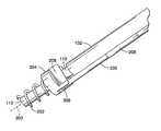
- FIG. 1is a perspective view of a system for placing an epicardial lead, or other electrical lead, including a drive shaft and lead body extending distally into a handle and a delivery catheter containing the drive shaft and lead body extending distally from the handle.
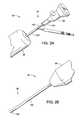
- FIG. 2Ais a fragmentary, perspective view of the proximal portion of the system of FIG. 1 , including an eyepiece coupled to the drive shaft for viewing through a fiber optic shaft disposed through the drive shaft.
- FIG. 2Bis a fragmentary, perspective view of the distal portion of the system of FIG. 1 , showing the delivery tube extending from the handle and terminating in a mapping electrode tip.
- FIG. 3is a perspective view of the system of FIG. 1 , having the handle and delivery catheter removed, showing the lead head releasably coupled to the drive shaft.
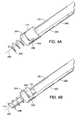
- FIG. 4Bis a fragmentary, perspective view of the lead and drive shaft of FIG. 4A , with the lead head engagement member of the drive shaft removed.
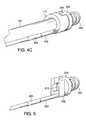
- FIG. 4Cis a fragmentary, perspective view of the lead and drive shaft of FIG. 4A , showing the lead engagement member coupled to the drive shaft for releasably engaging the lead head.
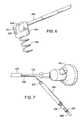
- FIG. 5is a fragmentary, perspective view of a distal portion of the lead of FIG. 4A , showing the aperture through the lead head for receiving a fiber optic probe.
- FIG. 7is a fragmentary, perspective view of the proximal portion of the lead, showing the lead connector.
- FIG. 8is a perspective view of another device according to the present invention including a delivery sheath with a proximal handle and a proximal handle extension, having a rotatable drive shaft handle coupled to a drive shaft rotatably disposed within the flexible delivery sheath, the drive shaft handle releasably receiving a proximal connector of the lead body, the tubular drive shaft having a fiber optic shaft received within.
- FIG. 9is a fragmentary, perspective view of the device of FIG. 8 including the delivery sheath handle, handle extension, drive shaft handle, lead proximal connector, and a proximal eyepiece coupled to the fiber optic shaft disposed within the tubular drive shaft.
- FIG. 11is another perspective view of the device of FIG. 8 , showing the terminal mapping electrode on the delivery sheath and the pin on the underside of the delivery sheath proximal handle which is electrically coupled to the terminal mapping electrode.
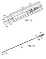
- FIG. 12is a fragmentary, perspective view of the device of FIG. 8 , showing the drive shaft handle receiving the lead body proximal connector, with the lead body extending along-side the drive shaft.
- FIG. 13is a perspective view of the device of FIG. 8 , showing the drive shaft extending from the drive shaft handle, the lead body, lead distal electrode, and lead proximal connector.
- FIG. 16is a perspective view of the device of FIG. 8 , showing the flexible delivery sheath proximal handle and extension including a rotatable locking ring for allowing the locking and releasing of the fiber optic proximal eyepiece.
- FIGS. 18A and 18Bare fragmentary, perspective views of one mechanism for coupling to the drive shaft handling for visually indicating the number of turns the drive shaft has been rotated.
- FIGS. 19A and 19Bare fragmentary, perspective views of another mechanism for coupling to the drive shaft handle, for visually indicating the number of turns the drive shaft has been rotated.
- FIGS. 20A and 20Bare fragmentary views of one helical electrode including a distal end having a larger radius of curvature and more pronounced helical angle than the proximal end.
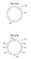
- FIGS. 21A and 21Bare end views of other terminal mapping electrodes.
- FIGS. 22A and 22Bare perspective views of another delivery system according to the present invention, having a locking mechanism for preventing advancement and/or rotation of the helical electrode during mapping.
- FIG. 1is a perspective view of a system 30 for delivering an electrical lead using minimally invasive techniques.
- System 30includes generally a proximal portion 32 , an intermediate portion 34 , and a distal portion 36 .
- Proximal portion 32can include a drive shaft 102 , the proximal portion of a lead body 200 , and the proximal connector 201 of the lead body.
- Drive shaft 102 and lead body 200extend into a handle 38 having a button 39 .
- button 39can be used to cause the distal end of the delivery tube to curve, allowing the user to steer the device.
- FIG. 1is a perspective view of a system 30 for delivering an electrical lead using minimally invasive techniques.
- System 30includes generally a proximal portion 32 , an intermediate portion 34 , and a distal portion 36 .
- Proximal portion 32can include a drive shaft 102 , the proximal portion of a lead body 200 , and the proximal connector
- buttons 39being slid, as indicated by arrows 41 , to cause the delivery tube 100 (discussed below) to curve and bend at the distal end to position 101 , as indicated by arrows 103 .
- a knobcan be rotated to cause the delivery tube to curve.
- the drive shaftis steerable instead of the delivery tube.
- Steerable devicessuch as steerable guide catheters and guide wires, are well known to those skilled in the art. Steerable devices are discussed in numerous U.S. patents and Patent Publications, including U.S. Patent Publication Nos. 2003/0130598 and 2003/0236493; and U.S. Pat. Nos. 3,605,725; 5,037,391; 5,571,161; 6,171,277; 6,500,130 and 6,530,914, all herein incorporated by reference.
- a delivery tube, delivery sheath, or delivery catheter (all used interchangeably) 100extends distally from handle 38 and terminates in a distal mapping electrode in some embodiments.
- Drive shaft 102 and lead body 200can extend side-by-side through the delivery catheter 100 .
- a fiber-optic probecan be slidably inserted through drive shaft 102 to distal portion 36 .
- system 30is about 18 in. long, with handle 38 being about 6 in. long.
- the lead bodycan be made of any suitable material, for example, a polymeric material, such as polyurethane or silicone rubber.
- the lead bodyis between about 6 inches and 36 inches long in some devices, and between about 1 and 48 inches long in other devices.
- the lead headmay be cylindrical in some leads, have an outer diameter of between about 1 mm and 32 mm, and a height of between about 1 and 20 mm.
- the electrodecan be of several various electrode types, such as helical, barbed, tined, or sutured.
- the proximal connectorcan be used to connect the lead to an implantable or external signal generator, such as a pacemaker, defibrillator, nerve stimulator, or muscle stimulator.
- the drive shaftmay be made of any suitable material, for example, a polymeric material, such as polyurethane or polyamide (nylon), and can be between about 6 and 36 inches long, or between about 1 and 48 inches long, and between about 1 mm and 20 mm in outer diameter.
- the drive shaft lumenmay be between about 0.5 mm and 3.0 mm, or between about 0.5 and 19 mm in inside diameter, in various embodiments.
- the delivery cathetercan be made of any suitable material, for example, a polymeric material, such as polyurethane or polyamide (nylon), and can have a length of between about 6 and 36 inches, or between about 1 and 48 inches, in various embodiments.
- the cathetercan have an outside diameter of between about 1 mm and 35 mm.
- the handlecan be made of a polymeric material, for example polyamide or ABS, and have an outer diameter of about 25 mm.
- the fiber optic probecan have a length of between about 6 and 36 inches, or between about 1 and 8 feet, in various embodiments. Fiber optic probes are available from many suppliers, for example, Medivision (Anaheim Calif.).
- FIG. 2Ashows proximal portion 32 of system 30 in more detail.
- Drive shaft 102is coupled to a drive nut 104 which is coupled to eyepiece 106 .
- Drive nut 104can be used to rotate drive shaft 102 about the fiber-optic shaft within in some embodiments. Some devices rotate eyepiece 106 and the fiber optic shaft along with drive nut 104 .
- Eyepiece 106can be used for viewing the visual image transmitted through a fiber-optic shaft disposed down drive shaft 102 . At the appropriate time, the eyepiece and coupled fiber optic shaft can be withdrawn from drive shaft 102 .
- Lead body 200 and drive shaft 102may be seen extending into handle 38 . When drive shaft 102 is rotated, in some embodiments, lead body 200 rotates with and about drive shaft 102 as the distal end of the lead is rotated into the tissue.
- FIG. 2Bbetter illustrates distal portion 36 of system 30 .
- Delivery tube or delivery catheter 100can be seen extending from handle 38 .
- delivery catheter 100includes a distal mapping electrode tip 108 .
- Mapping electrode 108can be used to test the electrical properties of the target site prior to implanting the electrode.
- electrode 108is coupled through a conductor, with the conductor extending through, within, or along, either integral with or separate from, delivery catheter 100 , to the proximal end of the device.
- FIG. 3illustrates lead body 200 and drive shaft 102 with the handle and delivery catheter removed.
- Lead body 200may be seen to terminate in a lead head 204 coupled to a helical electrode 202 .
- Drive shaft 102may be seen to terminate in a lead head engagement member or drive element 110 .
- Rotating drive shaft 102rotates drive element 110 which in turn rotates lead head 204 which also rotates helical electrode 202 , in the embodiment shown.
- lead body 200is fixed in a groove in drive shaft 102 .
- the connector 201may be secured, for example, with a clip secured to eyepiece 106 and/or drive nut 104 (shown in FIG. 2A ).
- FIG. 4Ashows the distal portion of drive shaft 102 and lead body 200 , again with the delivery catheter removed.
- a second electrode 205is present in this embodiment, and is coupled to a conductor within lead body 200 .
- Electrode 205can be a band, coil, or ring extending around lead body 200 in some embodiments.
- Drive shaft 102is connected to lead head engagement member or drive element 110 .
- Lead head engagement number 110is releasably engaged to a protrusion or blade 208 on lead head 204 , which carries helical electrode 202 .
- Lead body 200is coupled to lead head 204 at a point of attachment 206 .
- lead head drive member 110has a cavity or slot which engages lead head protrusion or blade 208 .
- Helix 202has a central longitudinal axis 203 extending through an interior portion of the helix.
- the fiber-optic probelooks down this central longitudinal axis 203 in the interior of helix 202 .
- the fiber optic probeextends through or into an aperture in the head disposed alongside the electrode. Inspection of FIG. 4A shows that rotating drive shaft 102 will also rotate lead head 204 and helix 202 . The releasable attachment of the drive shaft to the lead head can be accomplished using many mechanical designs well known to those skilled in the art.
- the various male and female corresponding membersmay be reversed as between the lead head and the drive member.
- FIG. 4Bagain shows the distal portion of lead body 200 , with the drive element 110 removed and a fiber optic shaft or probe 112 inserted into the interior of helix 202 . Blade or protrusion 208 may be better seen in this view.
- lead body 200is molded to lead head 204 at attachment point 206 , with the constrained configuration of lead body 200 being substantially parallel to drive shaft 102 as shown in FIG. 4B , such that the attachment point 206 is strained in the configuration shown in this figure, and in which helical central axis 203 will bend away from the central longitudinal axis of drive shaft 102 , when not constrained.
- helix 202will bend about 90° with respect to drive shaft 102 and lead body 200 , when unconstrained.
- attachment point 206includes an electrically conductive pivot, which can act to reduce the strain on lead body 200 in the configuration of FIG. 4B , but also allow the lead body to pivot with respect to lead head 204 after delivery and fixation of helix 202 into the target site tissue.
- sensorswhich can be acute monitoring sensors, are disposed near the distal tip of a shaft which is disposed along the same or similar path to that taken by fiber optic shaft 112 .
- shaftsmay resemble shaft 112 , a separate drawing in addition to FIG. 4B is not required.
- the types of sensorscould include but are not limited to temperature sensors, pressure sensors, oxygen sensors, pH sensors, chemical sensors, and combinations thereof. There could be more than one sensor at the tip depending on the application.
- the sensorcould also be used with the mapping electrode.
- the sensorcould be delivered through the drive shaft and the aperture in the lead head. Sensors could also be disposed where electrode 205 is located in FIG. 4B .
- the sensorscould generate a signal indicative of the property measured and transmit the signal along or through the shaft, for example using an electrical conductor or a fiber optic conductor.
- a fluorescent probeis disposed near a fiber optic shaft tip, which is used to measure one or more properties near the target tissue.
- FIG. 4Cillustrates the distal portion of the drive shaft and lead body.
- Lead body 200may be seen connecting to lead head 204 which carries helix 202 .
- Drive shaft 102carries drive element 110 which releasably engages protrusion or blade 208 on lead head 204 to rotate the lead head.
- FIG. 5illustrates lead body 200 coupled to lead head 204 .
- Lead head 204includes the blade or protrusion 208 , helix 202 , and also contains an aperture 210 therethrough.
- Aperture 210can receive a fiber-optic probe inserted into or through the aperture and also into the interior region of helical coil 202 , in some examples of the invention.
- Second electrode 205is also shown.
- FIG. 6shows lead body 200 coupled to lead head 204 bearing helix 202 .
- An interior slot or cavity 207may be seen in lead head 204 , with slot 207 housing part of lead body 200 within.
- lead body 200is actually configured to be attached at attachment point 206 on the far side of lead head 204 and to lie down partially within slot 207 within lead head 204 , which can provide additional strain relief.
- FIG. 7illustrates the proximal portion of system 30 previously discussed.
- An eyepiece 106is coupled to a fiber optic probe (not shown in FIG. 7 ) which is disposed within drive shaft 102 . Eyepiece 106 and the connected fiber optic shaft can be proximally retracted from within drive shaft 102 at the proper time, for example, after site visualization or lead fixation.
- Lead body 200may be seen coupled to a strain relief portion 230 .
- the connector portion of the leadincludes generally a connector sleeve 220 , a connector ring 222 , a seal 224 , and a connector pin 226 .
- FIG. 8illustrates another device 300 according to the present invention.
- Device 300includes a flexible, steerable delivery tube or sheath 302 having a distal mapping ring electrode 304 .
- Flexible sheath 302is coupled to a control handle 306 having a proximal handle extension 308 .
- a drive shaft(not shown in FIG. 8 ) is coupled to a proximal drive shaft handle 312 having a bushing 314 rotatably disposed within handle 306 .
- Drive shaft handle 312includes a cradle for receiving a lead proximal connector 310 .
- Drive shaft handle 312can be used to rotate both the drive shaft within flexible sheath 302 and the lead body connected to lead proximal connector 310 .
- Handle extension 308includes a receiver 318 for releasably securing a fiber optic eyepiece 316 which is coupled to a fiber optic shaft (not shown in FIG. 8 ) which can extend down the center of the tubular drive shaft disposed within the flexible sheath 302 .
- FIG. 9illustrates the proximal region of device 300 in more detail.
- Handle 306includes a rotatable knob 320 for controllably bending or steering delivery sheath 302 .
- Such control mechanismsare well known to those skilled in the art, and are the subject of several patents and patent applications assigned both to the assignee of the present patent application and others. Such controlled bending mechanisms do not require further discussion here.
- Handle extension 308receives bushing 314 coupled to drive handle 312 which houses lead proximal connector 310 .
- Bushing 314can rotate within handle 306 allowing drive handle 312 to rotatably screw a helical electrode into the target tissue.
- outer spiral groovesare included either in the outside surface of bushing 314 or drive shaft handle 312 , allowing a lead body having excess length to be dressed, thereby allowing leads having multiple lengths to be delivered with the same device.
- a lead body(not visible in FIG. 9 ) is coupled to proximal connector 310 and may lie along the outside of bushing 314 in a groove.
- Device 300can include a fiber-optic eyepiece receiver 318 having a locking ring 324 .
- Locking ring 324can have a C-shape, such that a fiber optic eyepiece 316 can be manually or mechanically advanced or retracted and/or released from the fiber-optic eyepiece receiver 318 by aligning the opening in the C-shape locking ring with the slot visible in the receiver 318 .
- a light admission port 322is visible, disposed in the slot, allowing light to be shined into the fiber optic shaft extending from the eyepiece 316 down through flexible sheath 302 .
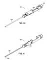
- FIG. 10offers another view of device 300 , showing a fiber optic shaft 326 coupled to eyepiece 316 .
- the drive shaft handle and leadhave been removed.
- fiber optic shaft 326is disposed within the tubular drive shaft. In such embodiments, the fiber optic shaft may be removed and reused.
- fiber optic shaft 326is disposed within a portion of the flexible delivery sheath 302 . In one such embodiment, the fiber optic shaft is slidably disposed within a separate lumen within the flexible sheath wall. In still another embodiment, the fiber optic shaft is fixedly secured within the flexible sheath or drive shaft, cannot be removed easily, and may be intended to serve as a single-use product.
- FIG. 11shows the underside of device 300 .
- the undersideincludes an electrical terminal connector 328 which is electrically coupled to ring mapping electrode 304 in some embodiments.
- Connector 328may be referred to as a “PSA” connector.
- Connector 328 in conjunction with electrode 304can be used to map the surface of the tissue on which the electrode is to be placed. This can be done by bending sheath 302 and contacting various tissue sites, while monitoring the electrical characteristics through a device coupled to connector 328 .
- FIG. 12illustrates drive shaft handle 312 having a cradle or receiving area for receiving lead proximal connector 310 .
- Proximal connector 310can be a standard size electrical connector, e.g. IS1, well known to those skilled in the art.
- Handle 312can include bushing 314 which can be rotatably disposed within the handle.
- Lead proximal connector 310is coupled to a lead body 330 , which can lie within a groove 332 in bushing 314 .
- some embodimentscan include a spiral outer groove 333 for dressing excess lead length around the bushing in a controllable manner.
- bushing 314may include a rotation indicator and/or counter and/or limiter, in some embodiments.
- FIG. 13shows drive shaft 334 coupled to a lead head engagement member 338 which is engaged to a lead head 336 .
- Lead body 334is coupled to lead proximal connector 310 which is received within drive shaft proximal handle 312 , as previously described.
- Lead body 334is dressed in groove 332 formed in bushing 314 .
- FIG. 14shows drive shaft 334 coupled to lead head engagement member 338 which is engaging lead head 336 .
- Lead head 336includes ears 342 which are engageably received by channels 344 in lead head engagement member 338 .
- Helix electrode 340may also be seen, having an aperture therethrough which may slidably receive a fiber-optic shaft in some embodiments.
- FIG. 15shows helix electrode 340 coupled to lead head 342 having ears 346 .
- Lead body 330may be seen, also carrying a ring electrode 346 , which may be present in some embodiments of the invention.
- ring electrode 346may serve as an anode.
- the drive shaft and the fiber optic shafthave been removed to more clearly show the lead distal region.
- FIG. 17shows eyepiece 316 with light admission port 322 coupled to fiber optic shaft 326 .
- Fiber-optic shaft 326in this embodiment, is slidably disposed into drive shaft handle 312 and into drive shaft 334 .
- Lead body 330extends side-by-side along drive shaft 334 in this embodiment. Lead body 330 extends through longitudinal groove 332 and is coupled to proximal lead connector 310 .
- FIG. 18Aillustrates a mechanism 352 for replacing bushing 314 and/or receiving aperture 348 , illustrated in FIGS. 9 and 16 , respectively.
- bushing (or inner shaft) 354can be received within tube 356 .
- Bushing 354is referred to as a bushing for the sake of continuity; even though in various embodiments this part may serve as a threaded member and even have rotation indicating mechanisms incorporated therein.
- Bushing 354 and tube 356can be cooperatively threaded to allow the rotation of bushing 354 within tube 356 to also advance bushing 354 longitudinally within tube 356 .
- a slot 358 within tube 356allows a portion of bushing 354 to be visible through the slot.
- a visual marker, dot 362indicates the longitudinal and rotational progression of bushing 354 within tube 356 .
- dot 362will progress from zero, 1, 2, to 3. In this way, the treating physician can easily keep track of the number of turns that the helical electrode has been rotated into the tissue.
- FIG. 18Bshows dot 362 as it has progressed to the two rotation mark within slot 358 .
- FIG. 19Ashows yet another mechanism 370 for tracking the rotational progress of the drive shaft and helical electrode into the tissue.
- Mechanism 370includes a bushing (or inner shaft) 372 having visual counting indicia 374 (including numbers 0, 1, 2, and 3, in this embodiment).
- Bushing 374is disposed within an outer tube 378 , which can be cooperatively helically threaded with bushing 374 such that the rotational progress of tube 374 is accompanied by a longitudinal progression within tube 378 .
- Mechanism 370includes a wider shoulder portion 376 which limits the longitudinal and rotational progression of bushing 372 within tube 378 . In this embodiment, only a little more than three rotations are allowed by the wider limiting shoulder 376 .
- shoulder 376may itself be part of a outer tube which is threadably and rotatably secured about bushing 372 , thereby allowing the number of rotations itself to be varied by changing the longitudinal position of shoulder region 376 with respect to bushing 374 . Once shoulder 376 contacts the receiving tube 378 , the rotation will be limited.
- FIG. 19Billustrates bushing 352 after it has been rotated about three turns into tube 378 and, presumably, into the tissue target site.
- an audible clicking mechanismprovides audible feedback as the rotation of the drive shaft handle is performed.
- the number of clickscan thus provide an indication to the treating physician of the progress of the rotation of the helical electrode.
- a clutch or slip mechanismonly transmits the rotation of the drive shaft handle up to a certain number of rotations, and, after that, causes rotation of the drive shaft handle to slip rather than transmit torque down the drive shaft.
- FIG. 20Ashows one helical electrode 400 including a distal region 406 and a proximal region 404 having a larger radius of curvature and more pronounced helical angle in the distal region.
- the proximal inter-turn distanceis indicated at 402 , where the distal inter-turn distance would be much greater, if a turn was ever completed.
- FIG. 20Bshows another helical coil 410 having distal region 414 and proximal region 412 .
- the distal region coil turnshave an angle indicated at 418 (with respect to an orthogonal plane through the coil center longitudinal axis), which is greater than the angle in the proximal region, indicated at 416 .
- FIG. 21Ais an end view of a terminal mapping electrode 430 , having a conductive region 432 and a non-conductive region 434 .
- the conductive regionmay describe only 90, 120, or 180 degrees of arc. The smaller arc can allow the physician to more accurately locate an optimal placement site.
- FIG. 21Bis an end view of a terminal mapping electrode 440 , having separate conductive regions 442 separated by insulating or non-conductive regions.
- separate conductorsallow any or all of the separate conductor regions to be individually accessed from the proximal handle region of the device.
- sensorswhich can be acute monitoring sensors, are disposed near the distal tip of the delivery tube, in addition to or in place of the one or more mapping electrodes.
- sensorsmay resemble electrodes 432 or 442 , a separate drawing in addition to FIGS. 21A and 21B is not required.
- the types of sensorscould include but are not limited to temperature sensors, pressure sensors, oxygen sensors, pH sensors, chemical sensors, and combinations thereof. There could be more than one sensor at the tip depending on the application.
- One or more of electrodes 442 in FIG. 21Bcould be sensors, for example, each of the four electrodes 442 could be a different type of sensor. The sensor or sensors could also be used in conjunction with the mapping electrode.
- FIGS. 22A and 22Billustrate another delivery system 450 according to the present invention, including a handle 458 , a handle extension 460 , a drive shaft handle 452 , a drive shaft handle distal bushing 454 , a controllably bendable delivery catheter 474 , a terminal mapping electrode 472 , and a drive shaft handle proximal bushing 455 .
- a distal region slot 476is formed through the catheter side wall in this embodiment. Slot or aperture 476 can be used in conjunction with an electrode within (e.g. electrode 346 in FIG. 15 ) for mapping while the terminal electrode is still disposed within the delivery catheter. Some such apertures are shorter or even circular in configuration.
- a locking button 456is provided for preventing unwanted advancement of the helical electrode during mapping. In this embodiment, FIG. 22B shows locking button 456 actuating a locking pin 462 to prevent rotation and/or advancement of drive shaft handle 452 within proximal bushing 455 .
- the leadcan be delivered using a catheter.
- the cathetercan be deflectable or steerable and may have a mapping electrode at the distal tip.
- the leadcan be loaded into the catheter, along-side or within the drive shaft.
- the proximal end or connector of the leadcan be secured to the drive shaft in some methods.
- the distal visualization device(for example, a fiber optic scope or solid state camera) can be placed down the lumen of the drive shaft and through the aperture in the lead head in some methods.
- the distal visualization devicemay be an integral part of one of the delivery tubes in other methods, and not require separate advancement or withdrawal.
- the drive shaft with the distal visualization device and the leadcan be passed down the catheter.
- the delivery cathetercan be placed through a port in the chest wall (for example a thorascopic or sub-xyphoid positioned port).
- the tipcan be placed between the pericardium and the epicardium and advanced to the desired location. The operator can then visualize the location using the scope.
- the deliverymay also be performed, as appropriate, through a mini thoracotomy, a transvenous puncture, or puncturing the right atrial appendage from within to gain access to the heart pericardium.
- the present inventionmay be used to place leads using minimally invasive techniques at other target sites. Intramuscular tissue sites are targeted in some methods. Placement of leads for gastric stimulation is another use of the present invention. Applications also include the visualized placement of spinal cord stimulation leads, neuro-stimulation leads, HIS bundle leads, LV apex leads, sensing leads, and others.
- the present inventionallows the location of the lead head to be visualized from the proximal region of the lead prior to placement of the lead electrode. In some embodiments, this is accomplished using a fiber optic probe having a shaft with a proximal eyepiece.
- the eyepieceis replaced with an electronic camera, for example, a CCD camera, for transmitting the image to a larger display or to an even more remote location.
- the fiber optic probe distal endmay be replaced with a small distal camera, for example a solid state camera on a chip.
- the optical image signal transmission function of the fiber optic shaftmay be replaced with an electronic image signal transmission function using an electrical signal conductor or a digital optical signal conductor.
- the distal end of either such probemay be referred to as an image capturing sensor.
- the optical fiber or electrical conductormay be referred to as an image transmitting conductor.
- the image capturing sensor and image transmitting conductormay be part of the delivery tube in some systems.
- the delivery catheterhas a conductive distal region which can be used to test the electrical properties of a potential site prior to fixing the electrode.
- the mapping tipis used to pace the heart.
- the mapping tipis used to provide electrical stimulation to other tissue, for example, nerve, muscle, or gastric tissue.
- the mapping tipis used to sense electrical activity from tissue, for example the heart, nerve, muscle, or other tissue. Such test stimulation or sensing may also be accomplished by using the lead electrode extending from the delivery catheter prior to fixing the electrode.
- the mapping electrodeis a terminal ring electrode on the distal tip of the delivery tube.
- the ringmay be masked in some embodiments, being conductive over only part of the ring, to better localize the mapping. In some such devices, only 180, 120, or 90 degrees of arc of the ring are conductive.
- the mapping electrode functionmay be performed using more than one electrode. In some such devices, the ring is separated into two semi-circular electrodes, three 120 arc degree electrodes, or four 90 arc degree electrodes, with each electrode having its own conductor extending back along the delivery tube to the handle.
- the delivery sheathhas one or more apertures through the side wall, allowing an electrode within to sense and/or stimulate tissue through the aperture in the side wall.
- the electrodeis a helical electrode
- the fixingincludes rotating the helical coil into the tissue.
- tissue penetrationis still accomplished, but with a barbed electrode. While surface, patch type electrode are less preferred, placement of such electrodes may also be accomplished using remote visualization of the target site.
- the fiber optic shaft and the drive shaftcan be retracted through the delivery tube, over or alongside the lead body.
- the delivery tubecan then be retracted over the lead body.
Landscapes
- Health & Medical Sciences (AREA)
- Life Sciences & Earth Sciences (AREA)
- Heart & Thoracic Surgery (AREA)
- Cardiology (AREA)
- General Health & Medical Sciences (AREA)
- Veterinary Medicine (AREA)
- Engineering & Computer Science (AREA)
- Biomedical Technology (AREA)
- Public Health (AREA)
- Animal Behavior & Ethology (AREA)
- Radiology & Medical Imaging (AREA)
- Nuclear Medicine, Radiotherapy & Molecular Imaging (AREA)
- Surgery (AREA)
- Physics & Mathematics (AREA)
- Molecular Biology (AREA)
- Medical Informatics (AREA)
- Pathology (AREA)
- Biophysics (AREA)
- Optics & Photonics (AREA)
- Neurosurgery (AREA)
- Vascular Medicine (AREA)
- Neurology (AREA)
- Orthopedic Medicine & Surgery (AREA)
- Surgical Instruments (AREA)
- Electrotherapy Devices (AREA)
Abstract
Description
Claims (67)
Priority Applications (3)
| Application Number | Priority Date | Filing Date | Title |
|---|---|---|---|
| US11/463,286US7844348B2 (en) | 2005-08-09 | 2006-08-08 | Fiber optic assisted medical lead |
| US12/955,417US8548603B2 (en) | 2005-08-09 | 2010-11-29 | Fiber optic assisted medical lead |
| US14/038,984US8868210B2 (en) | 2005-08-09 | 2013-09-27 | Fiber optic assisted medical lead |
Applications Claiming Priority (2)
| Application Number | Priority Date | Filing Date | Title |
|---|---|---|---|
| US59584005P | 2005-08-09 | 2005-08-09 | |
| US11/463,286US7844348B2 (en) | 2005-08-09 | 2006-08-08 | Fiber optic assisted medical lead |
Related Child Applications (1)
| Application Number | Title | Priority Date | Filing Date |
|---|---|---|---|
| US12/955,417DivisionUS8548603B2 (en) | 2005-08-09 | 2010-11-29 | Fiber optic assisted medical lead |
Publications (2)
| Publication Number | Publication Date |
|---|---|
| US20070038052A1 US20070038052A1 (en) | 2007-02-15 |
| US7844348B2true US7844348B2 (en) | 2010-11-30 |
Family
ID=37579221
Family Applications (3)
| Application Number | Title | Priority Date | Filing Date |
|---|---|---|---|
| US11/463,286Active2029-05-19US7844348B2 (en) | 2005-08-09 | 2006-08-08 | Fiber optic assisted medical lead |
| US12/955,417Active2026-09-13US8548603B2 (en) | 2005-08-09 | 2010-11-29 | Fiber optic assisted medical lead |
| US14/038,984ActiveUS8868210B2 (en) | 2005-08-09 | 2013-09-27 | Fiber optic assisted medical lead |
Family Applications After (2)
| Application Number | Title | Priority Date | Filing Date |
|---|---|---|---|
| US12/955,417Active2026-09-13US8548603B2 (en) | 2005-08-09 | 2010-11-29 | Fiber optic assisted medical lead |
| US14/038,984ActiveUS8868210B2 (en) | 2005-08-09 | 2013-09-27 | Fiber optic assisted medical lead |
Country Status (4)
| Country | Link |
|---|---|
| US (3) | US7844348B2 (en) |
| EP (1) | EP1912700B1 (en) |
| CA (1) | CA2619624C (en) |
| WO (1) | WO2007019576A2 (en) |
Cited By (86)
| Publication number | Priority date | Publication date | Assignee | Title |
|---|---|---|---|---|
| US20080132970A1 (en)* | 2006-12-05 | 2008-06-05 | Giancarlo Barolat | Method and system for treatment of intractable scrotal and/or testicular pain |
| US20150025350A1 (en)* | 2013-07-19 | 2015-01-22 | Biotronik Se & Co. Kg | Electrode With Guide Tunnel for a Cannula, and Kit Comprising Electrode and Cannula |
| US9526909B2 (en) | 2014-08-28 | 2016-12-27 | Cardiac Pacemakers, Inc. | Medical device with triggered blanking period |
| US9592391B2 (en) | 2014-01-10 | 2017-03-14 | Cardiac Pacemakers, Inc. | Systems and methods for detecting cardiac arrhythmias |
| US9669230B2 (en) | 2015-02-06 | 2017-06-06 | Cardiac Pacemakers, Inc. | Systems and methods for treating cardiac arrhythmias |
| US9853743B2 (en) | 2015-08-20 | 2017-12-26 | Cardiac Pacemakers, Inc. | Systems and methods for communication between medical devices |
| US9956414B2 (en) | 2015-08-27 | 2018-05-01 | Cardiac Pacemakers, Inc. | Temporal configuration of a motion sensor in an implantable medical device |
| US9968787B2 (en) | 2015-08-27 | 2018-05-15 | Cardiac Pacemakers, Inc. | Spatial configuration of a motion sensor in an implantable medical device |
| US10029107B1 (en) | 2017-01-26 | 2018-07-24 | Cardiac Pacemakers, Inc. | Leadless device with overmolded components |
| US10050700B2 (en) | 2015-03-18 | 2018-08-14 | Cardiac Pacemakers, Inc. | Communications in a medical device system with temporal optimization |
| US10046167B2 (en) | 2015-02-09 | 2018-08-14 | Cardiac Pacemakers, Inc. | Implantable medical device with radiopaque ID tag |
| US10065041B2 (en) | 2015-10-08 | 2018-09-04 | Cardiac Pacemakers, Inc. | Devices and methods for adjusting pacing rates in an implantable medical device |
| US10092760B2 (en) | 2015-09-11 | 2018-10-09 | Cardiac Pacemakers, Inc. | Arrhythmia detection and confirmation |
| US10137305B2 (en) | 2015-08-28 | 2018-11-27 | Cardiac Pacemakers, Inc. | Systems and methods for behaviorally responsive signal detection and therapy delivery |
| US10159842B2 (en) | 2015-08-28 | 2018-12-25 | Cardiac Pacemakers, Inc. | System and method for detecting tamponade |
| US10183170B2 (en) | 2015-12-17 | 2019-01-22 | Cardiac Pacemakers, Inc. | Conducted communication in a medical device system |
| US10213610B2 (en) | 2015-03-18 | 2019-02-26 | Cardiac Pacemakers, Inc. | Communications in a medical device system with link quality assessment |
| US10220213B2 (en) | 2015-02-06 | 2019-03-05 | Cardiac Pacemakers, Inc. | Systems and methods for safe delivery of electrical stimulation therapy |
| US10226631B2 (en) | 2015-08-28 | 2019-03-12 | Cardiac Pacemakers, Inc. | Systems and methods for infarct detection |
| US10328272B2 (en) | 2016-05-10 | 2019-06-25 | Cardiac Pacemakers, Inc. | Retrievability for implantable medical devices |
| US10350423B2 (en) | 2016-02-04 | 2019-07-16 | Cardiac Pacemakers, Inc. | Delivery system with force sensor for leadless cardiac device |
| US10357159B2 (en) | 2015-08-20 | 2019-07-23 | Cardiac Pacemakers, Inc | Systems and methods for communication between medical devices |
| US10391319B2 (en) | 2016-08-19 | 2019-08-27 | Cardiac Pacemakers, Inc. | Trans septal implantable medical device |
| US10413733B2 (en) | 2016-10-27 | 2019-09-17 | Cardiac Pacemakers, Inc. | Implantable medical device with gyroscope |
| US10426962B2 (en) | 2016-07-07 | 2019-10-01 | Cardiac Pacemakers, Inc. | Leadless pacemaker using pressure measurements for pacing capture verification |
| US10434317B2 (en) | 2016-10-31 | 2019-10-08 | Cardiac Pacemakers, Inc. | Systems and methods for activity level pacing |
| US10434314B2 (en) | 2016-10-27 | 2019-10-08 | Cardiac Pacemakers, Inc. | Use of a separate device in managing the pace pulse energy of a cardiac pacemaker |
| US10463305B2 (en) | 2016-10-27 | 2019-11-05 | Cardiac Pacemakers, Inc. | Multi-device cardiac resynchronization therapy with timing enhancements |
| US10512784B2 (en) | 2016-06-27 | 2019-12-24 | Cardiac Pacemakers, Inc. | Cardiac therapy system using subcutaneously sensed P-waves for resynchronization pacing management |
| US10561330B2 (en) | 2016-10-27 | 2020-02-18 | Cardiac Pacemakers, Inc. | Implantable medical device having a sense channel with performance adjustment |
| US10583303B2 (en) | 2016-01-19 | 2020-03-10 | Cardiac Pacemakers, Inc. | Devices and methods for wirelessly recharging a rechargeable battery of an implantable medical device |
| US10583301B2 (en) | 2016-11-08 | 2020-03-10 | Cardiac Pacemakers, Inc. | Implantable medical device for atrial deployment |
| US10617874B2 (en) | 2016-10-31 | 2020-04-14 | Cardiac Pacemakers, Inc. | Systems and methods for activity level pacing |
| US10632313B2 (en) | 2016-11-09 | 2020-04-28 | Cardiac Pacemakers, Inc. | Systems, devices, and methods for setting cardiac pacing pulse parameters for a cardiac pacing device |
| US10639486B2 (en) | 2016-11-21 | 2020-05-05 | Cardiac Pacemakers, Inc. | Implantable medical device with recharge coil |
| US10668294B2 (en) | 2016-05-10 | 2020-06-02 | Cardiac Pacemakers, Inc. | Leadless cardiac pacemaker configured for over the wire delivery |
| US10688304B2 (en) | 2016-07-20 | 2020-06-23 | Cardiac Pacemakers, Inc. | Method and system for utilizing an atrial contraction timing fiducial in a leadless cardiac pacemaker system |
| US10722720B2 (en) | 2014-01-10 | 2020-07-28 | Cardiac Pacemakers, Inc. | Methods and systems for improved communication between medical devices |
| US10737102B2 (en) | 2017-01-26 | 2020-08-11 | Cardiac Pacemakers, Inc. | Leadless implantable device with detachable fixation |
| USD894396S1 (en) | 2019-03-08 | 2020-08-25 | Pacesetter, Inc. | Leadless biostimulator attachment feature |
| US10758737B2 (en) | 2016-09-21 | 2020-09-01 | Cardiac Pacemakers, Inc. | Using sensor data from an intracardially implanted medical device to influence operation of an extracardially implantable cardioverter |
| US10758724B2 (en) | 2016-10-27 | 2020-09-01 | Cardiac Pacemakers, Inc. | Implantable medical device delivery system with integrated sensor |
| US10765871B2 (en) | 2016-10-27 | 2020-09-08 | Cardiac Pacemakers, Inc. | Implantable medical device with pressure sensor |
| US10780278B2 (en) | 2016-08-24 | 2020-09-22 | Cardiac Pacemakers, Inc. | Integrated multi-device cardiac resynchronization therapy using P-wave to pace timing |
| US10821288B2 (en) | 2017-04-03 | 2020-11-03 | Cardiac Pacemakers, Inc. | Cardiac pacemaker with pacing pulse energy adjustment based on sensed heart rate |
| US10835753B2 (en) | 2017-01-26 | 2020-11-17 | Cardiac Pacemakers, Inc. | Intra-body device communication with redundant message transmission |
| US10870008B2 (en) | 2016-08-24 | 2020-12-22 | Cardiac Pacemakers, Inc. | Cardiac resynchronization using fusion promotion for timing management |
| US10874861B2 (en) | 2018-01-04 | 2020-12-29 | Cardiac Pacemakers, Inc. | Dual chamber pacing without beat-to-beat communication |
| US10881869B2 (en) | 2016-11-21 | 2021-01-05 | Cardiac Pacemakers, Inc. | Wireless re-charge of an implantable medical device |
| US10881863B2 (en) | 2016-11-21 | 2021-01-05 | Cardiac Pacemakers, Inc. | Leadless cardiac pacemaker with multimode communication |
| US10894163B2 (en) | 2016-11-21 | 2021-01-19 | Cardiac Pacemakers, Inc. | LCP based predictive timing for cardiac resynchronization |
| US10905872B2 (en) | 2017-04-03 | 2021-02-02 | Cardiac Pacemakers, Inc. | Implantable medical device with a movable electrode biased toward an extended position |
| US10905886B2 (en) | 2015-12-28 | 2021-02-02 | Cardiac Pacemakers, Inc. | Implantable medical device for deployment across the atrioventricular septum |
| US10905889B2 (en) | 2016-09-21 | 2021-02-02 | Cardiac Pacemakers, Inc. | Leadless stimulation device with a housing that houses internal components of the leadless stimulation device and functions as the battery case and a terminal of an internal battery |
| US10918875B2 (en) | 2017-08-18 | 2021-02-16 | Cardiac Pacemakers, Inc. | Implantable medical device with a flux concentrator and a receiving coil disposed about the flux concentrator |
| US10994145B2 (en) | 2016-09-21 | 2021-05-04 | Cardiac Pacemakers, Inc. | Implantable cardiac monitor |
| US11052258B2 (en) | 2017-12-01 | 2021-07-06 | Cardiac Pacemakers, Inc. | Methods and systems for detecting atrial contraction timing fiducials within a search window from a ventricularly implanted leadless cardiac pacemaker |
| US11058880B2 (en) | 2018-03-23 | 2021-07-13 | Medtronic, Inc. | VFA cardiac therapy for tachycardia |
| US11065459B2 (en) | 2017-08-18 | 2021-07-20 | Cardiac Pacemakers, Inc. | Implantable medical device with pressure sensor |
| US11071870B2 (en) | 2017-12-01 | 2021-07-27 | Cardiac Pacemakers, Inc. | Methods and systems for detecting atrial contraction timing fiducials and determining a cardiac interval from a ventricularly implanted leadless cardiac pacemaker |
| US11116988B2 (en) | 2016-03-31 | 2021-09-14 | Cardiac Pacemakers, Inc. | Implantable medical device with rechargeable battery |
| US11147979B2 (en) | 2016-11-21 | 2021-10-19 | Cardiac Pacemakers, Inc. | Implantable medical device with a magnetically permeable housing and an inductive coil disposed about the housing |
| US11185703B2 (en) | 2017-11-07 | 2021-11-30 | Cardiac Pacemakers, Inc. | Leadless cardiac pacemaker for bundle of his pacing |
| US11185704B2 (en) | 2017-11-06 | 2021-11-30 | Pacesetter, Inc. | Biostimulator having fixation element |
| US11207532B2 (en) | 2017-01-04 | 2021-12-28 | Cardiac Pacemakers, Inc. | Dynamic sensing updates using postural input in a multiple device cardiac rhythm management system |
| US11207527B2 (en) | 2016-07-06 | 2021-12-28 | Cardiac Pacemakers, Inc. | Method and system for determining an atrial contraction timing fiducial in a leadless cardiac pacemaker system |
| US11213676B2 (en) | 2019-04-01 | 2022-01-04 | Medtronic, Inc. | Delivery systems for VfA cardiac therapy |
| US11235163B2 (en) | 2017-09-20 | 2022-02-01 | Cardiac Pacemakers, Inc. | Implantable medical device with multiple modes of operation |
| US11235159B2 (en) | 2018-03-23 | 2022-02-01 | Medtronic, Inc. | VFA cardiac resynchronization therapy |
| US11235161B2 (en) | 2018-09-26 | 2022-02-01 | Medtronic, Inc. | Capture in ventricle-from-atrium cardiac therapy |
| US11260216B2 (en) | 2017-12-01 | 2022-03-01 | Cardiac Pacemakers, Inc. | Methods and systems for detecting atrial contraction timing fiducials during ventricular filling from a ventricularly implanted leadless cardiac pacemaker |
| US11285326B2 (en) | 2015-03-04 | 2022-03-29 | Cardiac Pacemakers, Inc. | Systems and methods for treating cardiac arrhythmias |
| US11305127B2 (en) | 2019-08-26 | 2022-04-19 | Medtronic Inc. | VfA delivery and implant region detection |
| US11400296B2 (en) | 2018-03-23 | 2022-08-02 | Medtronic, Inc. | AV synchronous VfA cardiac therapy |
| US11529523B2 (en) | 2018-01-04 | 2022-12-20 | Cardiac Pacemakers, Inc. | Handheld bridge device for providing a communication bridge between an implanted medical device and a smartphone |
| US11541243B2 (en) | 2019-03-15 | 2023-01-03 | Pacesetter, Inc. | Biostimulator having coaxial fixation elements |
| US11577086B2 (en) | 2018-08-20 | 2023-02-14 | Pacesetter, Inc. | Fixation mechanisms for a leadless cardiac biostimulator |
| US11679265B2 (en) | 2019-02-14 | 2023-06-20 | Medtronic, Inc. | Lead-in-lead systems and methods for cardiac therapy |
| US11697025B2 (en) | 2019-03-29 | 2023-07-11 | Medtronic, Inc. | Cardiac conduction system capture |
| US11712188B2 (en) | 2019-05-07 | 2023-08-01 | Medtronic, Inc. | Posterior left bundle branch engagement |
| US11813464B2 (en) | 2020-07-31 | 2023-11-14 | Medtronic, Inc. | Cardiac conduction system evaluation |
| US11813466B2 (en) | 2020-01-27 | 2023-11-14 | Medtronic, Inc. | Atrioventricular nodal stimulation |
| US11813463B2 (en) | 2017-12-01 | 2023-11-14 | Cardiac Pacemakers, Inc. | Leadless cardiac pacemaker with reversionary behavior |
| US11911168B2 (en) | 2020-04-03 | 2024-02-27 | Medtronic, Inc. | Cardiac conduction system therapy benefit determination |
| US11951313B2 (en) | 2018-11-17 | 2024-04-09 | Medtronic, Inc. | VFA delivery systems and methods |
| US12296177B2 (en) | 2018-12-21 | 2025-05-13 | Medtronic, Inc. | Delivery systems and methods for left ventricular pacing |
Families Citing this family (83)
| Publication number | Priority date | Publication date | Assignee | Title |
|---|---|---|---|---|
| US7844348B2 (en) | 2005-08-09 | 2010-11-30 | Greatbatch Ltd. | Fiber optic assisted medical lead |
| WO2008108901A1 (en)* | 2006-12-28 | 2008-09-12 | Medtronic, Inc | Chronically-implantable active fixation medical electrical leads and related methods for non-fluoroscopic implantation |
| US10166066B2 (en) | 2007-03-13 | 2019-01-01 | University Of Virginia Patent Foundation | Epicardial ablation catheter and method of use |
| WO2008118737A1 (en) | 2007-03-22 | 2008-10-02 | University Of Virginia Patent Foundation | Electrode catheter for ablation purposes and related method thereof |
| US11058354B2 (en) | 2007-03-19 | 2021-07-13 | University Of Virginia Patent Foundation | Access needle with direct visualization and related methods |
| US9468396B2 (en) | 2007-03-19 | 2016-10-18 | University Of Virginia Patent Foundation | Systems and methods for determining location of an access needle in a subject |
| WO2011103456A2 (en) | 2010-02-18 | 2011-08-25 | University Of Virginia Patent Foundation | System, method, and computer program product for simulating epicardial electrophysiology procedures |
| BRPI0809127B8 (en) | 2007-03-19 | 2021-06-22 | Univ Virginia Patent Foundation | devices and methods for accessing one or more locations and detecting pressure at one or more locations |
| CN101711125B (en)* | 2007-04-18 | 2016-03-16 | 美敦力公司 | Long-term implantable active fixed medical electronic leads for non-fluoroscopy implants |
| US20100241185A1 (en) | 2007-11-09 | 2010-09-23 | University Of Virginia Patent Foundation | Steerable epicardial pacing catheter system placed via the subxiphoid process |
| US8364277B2 (en)* | 2008-01-10 | 2013-01-29 | Bioness Inc. | Methods and apparatus for implanting electronic implants within the body |
| US8801665B2 (en) | 2008-04-10 | 2014-08-12 | Henry Ford Health System | Apparatus and method for controlled depth of injection into myocardial tissue |
| US8839798B2 (en)* | 2008-04-18 | 2014-09-23 | Medtronic, Inc. | System and method for determining sheath location |
| US8340751B2 (en) | 2008-04-18 | 2012-12-25 | Medtronic, Inc. | Method and apparatus for determining tracking a virtual point defined relative to a tracked member |
| US8494608B2 (en)* | 2008-04-18 | 2013-07-23 | Medtronic, Inc. | Method and apparatus for mapping a structure |
| US8260395B2 (en)* | 2008-04-18 | 2012-09-04 | Medtronic, Inc. | Method and apparatus for mapping a structure |
| US8663120B2 (en)* | 2008-04-18 | 2014-03-04 | Regents Of The University Of Minnesota | Method and apparatus for mapping a structure |
| US8532734B2 (en) | 2008-04-18 | 2013-09-10 | Regents Of The University Of Minnesota | Method and apparatus for mapping a structure |
| US9788790B2 (en) | 2009-05-28 | 2017-10-17 | Avinger, Inc. | Optical coherence tomography for biological imaging |
| US8696695B2 (en) | 2009-04-28 | 2014-04-15 | Avinger, Inc. | Guidewire positioning catheter |
| US9125562B2 (en) | 2009-07-01 | 2015-09-08 | Avinger, Inc. | Catheter-based off-axis optical coherence tomography imaging system |
| US8062316B2 (en) | 2008-04-23 | 2011-11-22 | Avinger, Inc. | Catheter system and method for boring through blocked vascular passages |
| CA2867999C (en)* | 2008-05-06 | 2016-10-04 | Intertape Polymer Corp. | Edge coatings for tapes |
| US9513443B2 (en) | 2008-05-28 | 2016-12-06 | John Lawrence Erb | Optical fiber-fine wire conductor and connectors |
| US8494650B2 (en)* | 2008-08-07 | 2013-07-23 | Bioness, Inc. | Insertion tools and methods for an electrical stimulation implant |
| US9403020B2 (en) | 2008-11-04 | 2016-08-02 | Nevro Corporation | Modeling positions of implanted devices in a patient |
| US8175681B2 (en) | 2008-12-16 | 2012-05-08 | Medtronic Navigation Inc. | Combination of electromagnetic and electropotential localization |
| WO2011003006A2 (en) | 2009-07-01 | 2011-01-06 | Avinger, Inc. | Atherectomy catheter with laterally-displaceable tip |
| US8494613B2 (en) | 2009-08-31 | 2013-07-23 | Medtronic, Inc. | Combination localization system |
| US8494614B2 (en) | 2009-08-31 | 2013-07-23 | Regents Of The University Of Minnesota | Combination localization system |
| US8446934B2 (en)* | 2009-08-31 | 2013-05-21 | Texas Instruments Incorporated | Frequency diversity and phase rotation |
| US9642534B2 (en) | 2009-09-11 | 2017-05-09 | University Of Virginia Patent Foundation | Systems and methods for determining location of an access needle in a subject |
| US8355774B2 (en)* | 2009-10-30 | 2013-01-15 | Medtronic, Inc. | System and method to evaluate electrode position and spacing |
| US20130102858A1 (en)* | 2010-06-18 | 2013-04-25 | St. Jude Medical Ab | Implantable sensor device and system |
| US10548478B2 (en) | 2010-07-01 | 2020-02-04 | Avinger, Inc. | Balloon atherectomy catheters with imaging |
| US11382653B2 (en) | 2010-07-01 | 2022-07-12 | Avinger, Inc. | Atherectomy catheter |
| WO2014039096A1 (en) | 2012-09-06 | 2014-03-13 | Avinger, Inc. | Re-entry stylet for catheter |
| US9345510B2 (en) | 2010-07-01 | 2016-05-24 | Avinger, Inc. | Atherectomy catheters with longitudinally displaceable drive shafts |
| US8965482B2 (en) | 2010-09-30 | 2015-02-24 | Nevro Corporation | Systems and methods for positioning implanted devices in a patient |
| US8805519B2 (en) | 2010-09-30 | 2014-08-12 | Nevro Corporation | Systems and methods for detecting intrathecal penetration |
| EP2691038B1 (en) | 2011-03-28 | 2016-07-20 | Avinger, Inc. | Occlusion-crossing devices, imaging, and atherectomy devices |
| US9949754B2 (en) | 2011-03-28 | 2018-04-24 | Avinger, Inc. | Occlusion-crossing devices |
| EP3653151A1 (en) | 2011-10-17 | 2020-05-20 | Avinger, Inc. | Atherectomy catheters and non-contact actuation mechanism for catheters |
| US20140243688A1 (en)* | 2011-10-28 | 2014-08-28 | Three Rivers Cardiovascular Systems Inc. | Fluid temperature and flow sensor apparatus and system for cardiovascular and other medical applications |
| US9345406B2 (en) | 2011-11-11 | 2016-05-24 | Avinger, Inc. | Occlusion-crossing devices, atherectomy devices, and imaging |
| US9778141B2 (en)* | 2012-01-31 | 2017-10-03 | Siemens Energy, Inc. | Video inspection system with deformable, self-supporting deployment tether |
| US9948835B2 (en)* | 2012-01-31 | 2018-04-17 | Siemens Energy, Inc. | Single-axis inspection scope with spherical camera and method for internal inspection of power generation machinery |
| WO2013172970A1 (en) | 2012-05-14 | 2013-11-21 | Avinger, Inc. | Atherectomy catheters with imaging |
| EP2849660B1 (en) | 2012-05-14 | 2021-08-25 | Avinger, Inc. | Atherectomy catheter drive assemblies |
| US9557156B2 (en) | 2012-05-14 | 2017-01-31 | Avinger, Inc. | Optical coherence tomography with graded index fiber for biological imaging |
| US11284916B2 (en) | 2012-09-06 | 2022-03-29 | Avinger, Inc. | Atherectomy catheters and occlusion crossing devices |
| US9498247B2 (en) | 2014-02-06 | 2016-11-22 | Avinger, Inc. | Atherectomy catheters and occlusion crossing devices |
| CN104884122B (en) | 2012-11-21 | 2016-12-07 | 纽佩斯公司 | Injectable Subcutaneous String Heart Device |
| CN105228514B (en) | 2013-03-15 | 2019-01-22 | 阿维格公司 | Optical Pressure Sensor Assembly |
| WO2014143064A1 (en) | 2013-03-15 | 2014-09-18 | Avinger, Inc. | Chronic total occlusion crossing devices with imaging |
| US11096717B2 (en) | 2013-03-15 | 2021-08-24 | Avinger, Inc. | Tissue collection device for catheter |
| US20150005740A1 (en)* | 2013-06-28 | 2015-01-01 | Boston Scientific Scimed, Inc. | Injection devices and related methods of use |
| EP3019096B1 (en) | 2013-07-08 | 2023-07-05 | Avinger, Inc. | System for identification of elastic lamina to guide interventional therapy |
| MX2016010141A (en) | 2014-02-06 | 2017-04-06 | Avinger Inc | Atherectomy catheters and occlusion crossing devices. |
| WO2015143327A1 (en) | 2014-03-21 | 2015-09-24 | Mayo Foundation For Medical Education And Research | Multi-electrode epicardial pacing |
| US10357277B2 (en)* | 2014-07-08 | 2019-07-23 | Avinger, Inc. | High speed chronic total occlusion crossing devices |
| US10434316B2 (en)* | 2014-09-08 | 2019-10-08 | Newpace Ltd. | Flexible rechargeable implantable subcutaneous medical device structure and method of assembly |
| EP3485939B1 (en)* | 2014-10-22 | 2020-07-15 | Cardiac Pacemakers, Inc. | Delivery devices for leadless cardiac devices |
| US9993648B2 (en)* | 2015-03-27 | 2018-06-12 | Medtronic, Inc. | Medical device delivery system |
| US10568520B2 (en) | 2015-07-13 | 2020-02-25 | Avinger, Inc. | Micro-molded anamorphic reflector lens for image guided therapeutic/diagnostic catheters |
| CN106644392B (en)* | 2015-07-20 | 2019-06-11 | 西门子能源公司 | Uniaxial ray examination observation device with spherical camera and the method for the internal check for generating project |
| JP6927986B2 (en) | 2016-01-25 | 2021-09-01 | アビンガー・インコーポレイテッドAvinger, Inc. | OCT imaging catheter with delay compensation |
| EP3435892B1 (en) | 2016-04-01 | 2024-04-03 | Avinger, Inc. | Atherectomy catheter with serrated cutter |
| EP3452164B1 (en)* | 2016-05-03 | 2023-04-26 | Newpace Ltd. | Flexible semi-hermetic implantable medical device structure |
| US11344327B2 (en) | 2016-06-03 | 2022-05-31 | Avinger, Inc. | Catheter device with detachable distal end |
| WO2018006041A1 (en) | 2016-06-30 | 2018-01-04 | Avinger, Inc. | Atherectomy catheter with shapeable distal tip |
| US11931163B2 (en) | 2017-02-23 | 2024-03-19 | Beth Israel Deaconess Medical Center, Inc. | Method and apparatus to determine the malignant potential of pancreatic cysts using light scattering spectroscopy |
| US10980999B2 (en) | 2017-03-09 | 2021-04-20 | Nevro Corp. | Paddle leads and delivery tools, and associated systems and methods |
| US11376039B2 (en)* | 2017-03-30 | 2022-07-05 | Medtronic, Inc. | Interventional medical systems and associated assemblies |
| WO2019191423A1 (en) | 2018-03-29 | 2019-10-03 | Nevro Corp. | Leads having sidewall openings, and associated systems and methods |
| US12167867B2 (en) | 2018-04-19 | 2024-12-17 | Avinger, Inc. | Occlusion-crossing devices |
| CN114746033B (en) | 2019-10-18 | 2025-01-10 | 阿维格公司 | Blocking crossing device |
| EP4051370A1 (en)* | 2019-11-01 | 2022-09-07 | BIOTRONIK SE & Co. KG | Implantable medical device comprising an anchoring device |
| CN111358547B (en)* | 2020-02-28 | 2021-07-09 | 杭州市第一人民医院 | An operating handle for transurethral prostate minimally invasive surgery |
| US11920915B2 (en)* | 2021-04-07 | 2024-03-05 | The Boeing Company | Non-contact measurement for interface gaps |
| WO2023088766A1 (en)* | 2021-11-18 | 2023-05-25 | Biotronik Se & Co. Kg | Implantable medical device comprising an electrode device having a helix element |
| DE102022107541A1 (en)* | 2022-03-30 | 2023-10-05 | Joimax Gmbh | Medical guidance instrument, medical instrument set, medical device and medical procedure |
| US20250041613A1 (en)* | 2023-08-03 | 2025-02-06 | Pacesetter, Inc. | Biostimulator having fixation guide |
Citations (21)
| Publication number | Priority date | Publication date | Assignee | Title |
|---|---|---|---|---|
| US4235246A (en) | 1979-02-05 | 1980-11-25 | Arco Medical Products Company | Epicardial heart lead and assembly and method for optimal fixation of same for cardiac pacing |
| EP0149431A2 (en) | 1983-10-25 | 1985-07-24 | C.B. BIOELETTRONICA S.r.l. | Active anchored intracavitary electrocatheter with retractible spring wire |
| US4628943A (en)* | 1985-06-21 | 1986-12-16 | Cordis Corporation | Bipolar screw-in packing lead assembly |
| EP0795343A2 (en) | 1996-02-21 | 1997-09-17 | Medtronic, Inc. | Medical electrical lead with surface treatment of the fixation helix |
| WO1999055412A1 (en) | 1998-04-29 | 1999-11-04 | Emory University | Cardiac pacing lead and delivery system |
| US6038463A (en)* | 1997-09-26 | 2000-03-14 | Medtronic, Inc. | Medical electrical lead |
| US20020165536A1 (en)* | 2000-03-31 | 2002-11-07 | Medtronic, Inc. | Method and system for delivery of a medical electrical lead within a venous system |
| WO2002087689A1 (en) | 2001-04-17 | 2002-11-07 | Medtronic, Inc. | Insulating member for a medical electrical lead |
| US20030187461A1 (en) | 1999-08-10 | 2003-10-02 | Chin Albert K. | Releasable guide and method for endoscopic cardiac lead placement |
| US20030212446A1 (en) | 2002-05-10 | 2003-11-13 | Kaplan Aaron V. | Methods and apparatus for lead placement on a surface of the heart |
| US20030220676A1 (en)* | 2002-05-21 | 2003-11-27 | John R. Helland | Electrode arrangements for body implantable pacing and sensing leads |
| US20040088035A1 (en) | 2002-10-30 | 2004-05-06 | Medtronic, Inc. | Methods and apparatus for accessing and stabilizing an area of the heart |
| US20040138527A1 (en) | 2003-01-15 | 2004-07-15 | Bonner Matthew D. | Methods and apparatus for accessing and stabilizing an area of the heart |
| US20040204734A1 (en) | 2003-04-11 | 2004-10-14 | Wagner Darrell Orvin | Tunneling tool with subcutaneous transdermal illumination |
| US20040230282A1 (en)* | 2003-04-11 | 2004-11-18 | Cates Adam W. | Acute and chronic fixation for subcutaneous electrodes |
| US20050004644A1 (en)* | 2003-05-06 | 2005-01-06 | Enpath Medical, Inc. | Rotatable lead introducer |
| US20050033394A1 (en) | 2003-08-08 | 2005-02-10 | Medtronic, Inc. | Medical electrical lead anchoring |
| US6890295B2 (en) | 2002-10-31 | 2005-05-10 | Medtronic, Inc. | Anatomical space access tools and methods |
| WO2005107851A1 (en) | 2004-04-28 | 2005-11-17 | Medtronic, Inc. | Novel lead body assemblies |
| US20060047333A1 (en)* | 2004-08-31 | 2006-03-02 | Tockman Bruce A | Sensor guided epicardial lead |
| US7369901B1 (en)* | 2004-02-11 | 2008-05-06 | Pacesetter, Inc. | Myocardial lead and lead system |
Family Cites Families (8)
| Publication number | Priority date | Publication date | Assignee | Title |
|---|---|---|---|---|
| US5628775A (en)* | 1991-11-08 | 1997-05-13 | Ep Technologies, Inc. | Flexible bond for sleeves enclosing a bendable electrode tip assembly |
| US5871532A (en)* | 1997-05-22 | 1999-02-16 | Sulzer Intermedics Inc. | Epicardial lead for minimally invasive implantation |
| US6192280B1 (en)* | 1999-06-02 | 2001-02-20 | Medtronic, Inc. | Guidewire placed implantable lead with tip seal |
| ATE308935T1 (en)* | 2000-08-14 | 2005-11-15 | Boston Scient Ltd | DIRECTORABLE SPHINCTEROTOME |
| US7016715B2 (en)* | 2003-01-13 | 2006-03-21 | Nellcorpuritan Bennett Incorporated | Selection of preset filter parameters based on signal quality |
| US8433396B2 (en)* | 2003-04-18 | 2013-04-30 | Medtronic, Inc. | Methods and apparatus for atrioventricular search |
| US20060136035A1 (en)* | 2004-12-20 | 2006-06-22 | Vascular Architects, Inc. A Delaware Corporation | Coiled endoluminal prosthesis system and delivery catheter |
| US7844348B2 (en) | 2005-08-09 | 2010-11-30 | Greatbatch Ltd. | Fiber optic assisted medical lead |
- 2006
- 2006-08-08USUS11/463,286patent/US7844348B2/enactiveActive
- 2006-08-09WOPCT/US2006/031288patent/WO2007019576A2/enactiveApplication Filing
- 2006-08-09CACA2619624Apatent/CA2619624C/ennot_activeExpired - Fee Related
- 2006-08-09EPEP06801201.2Apatent/EP1912700B1/ennot_activeNot-in-force
- 2010
- 2010-11-29USUS12/955,417patent/US8548603B2/enactiveActive
- 2013
- 2013-09-27USUS14/038,984patent/US8868210B2/enactiveActive
Patent Citations (22)
| Publication number | Priority date | Publication date | Assignee | Title |
|---|---|---|---|---|
| US4235246A (en) | 1979-02-05 | 1980-11-25 | Arco Medical Products Company | Epicardial heart lead and assembly and method for optimal fixation of same for cardiac pacing |
| EP0149431A2 (en) | 1983-10-25 | 1985-07-24 | C.B. BIOELETTRONICA S.r.l. | Active anchored intracavitary electrocatheter with retractible spring wire |
| US4628943A (en)* | 1985-06-21 | 1986-12-16 | Cordis Corporation | Bipolar screw-in packing lead assembly |
| EP0795343A2 (en) | 1996-02-21 | 1997-09-17 | Medtronic, Inc. | Medical electrical lead with surface treatment of the fixation helix |
| US6038463A (en)* | 1997-09-26 | 2000-03-14 | Medtronic, Inc. | Medical electrical lead |
| WO1999055412A1 (en) | 1998-04-29 | 1999-11-04 | Emory University | Cardiac pacing lead and delivery system |
| US20030187461A1 (en) | 1999-08-10 | 2003-10-02 | Chin Albert K. | Releasable guide and method for endoscopic cardiac lead placement |
| US20020165536A1 (en)* | 2000-03-31 | 2002-11-07 | Medtronic, Inc. | Method and system for delivery of a medical electrical lead within a venous system |
| WO2002087689A1 (en) | 2001-04-17 | 2002-11-07 | Medtronic, Inc. | Insulating member for a medical electrical lead |
| US20030212446A1 (en) | 2002-05-10 | 2003-11-13 | Kaplan Aaron V. | Methods and apparatus for lead placement on a surface of the heart |
| US20030220676A1 (en)* | 2002-05-21 | 2003-11-27 | John R. Helland | Electrode arrangements for body implantable pacing and sensing leads |
| US20040088035A1 (en) | 2002-10-30 | 2004-05-06 | Medtronic, Inc. | Methods and apparatus for accessing and stabilizing an area of the heart |
| US6890295B2 (en) | 2002-10-31 | 2005-05-10 | Medtronic, Inc. | Anatomical space access tools and methods |
| US20040138527A1 (en) | 2003-01-15 | 2004-07-15 | Bonner Matthew D. | Methods and apparatus for accessing and stabilizing an area of the heart |
| US20040138531A1 (en) | 2003-01-15 | 2004-07-15 | Bonner Matthew D. | Methods and apparatus for accessing and stabilizing an area of the heart |
| US20040204734A1 (en) | 2003-04-11 | 2004-10-14 | Wagner Darrell Orvin | Tunneling tool with subcutaneous transdermal illumination |
| US20040230282A1 (en)* | 2003-04-11 | 2004-11-18 | Cates Adam W. | Acute and chronic fixation for subcutaneous electrodes |
| US20050004644A1 (en)* | 2003-05-06 | 2005-01-06 | Enpath Medical, Inc. | Rotatable lead introducer |
| US20050033394A1 (en) | 2003-08-08 | 2005-02-10 | Medtronic, Inc. | Medical electrical lead anchoring |
| US7369901B1 (en)* | 2004-02-11 | 2008-05-06 | Pacesetter, Inc. | Myocardial lead and lead system |
| WO2005107851A1 (en) | 2004-04-28 | 2005-11-17 | Medtronic, Inc. | Novel lead body assemblies |
| US20060047333A1 (en)* | 2004-08-31 | 2006-03-02 | Tockman Bruce A | Sensor guided epicardial lead |
Non-Patent Citations (1)
| Title |
|---|
| International Search Report from Corresponding case. |
Cited By (105)
| Publication number | Priority date | Publication date | Assignee | Title |
|---|---|---|---|---|
| US20080132970A1 (en)* | 2006-12-05 | 2008-06-05 | Giancarlo Barolat | Method and system for treatment of intractable scrotal and/or testicular pain |
| US20150025350A1 (en)* | 2013-07-19 | 2015-01-22 | Biotronik Se & Co. Kg | Electrode With Guide Tunnel for a Cannula, and Kit Comprising Electrode and Cannula |
| US9592391B2 (en) | 2014-01-10 | 2017-03-14 | Cardiac Pacemakers, Inc. | Systems and methods for detecting cardiac arrhythmias |
| US10722720B2 (en) | 2014-01-10 | 2020-07-28 | Cardiac Pacemakers, Inc. | Methods and systems for improved communication between medical devices |
| US9526909B2 (en) | 2014-08-28 | 2016-12-27 | Cardiac Pacemakers, Inc. | Medical device with triggered blanking period |
| US9669230B2 (en) | 2015-02-06 | 2017-06-06 | Cardiac Pacemakers, Inc. | Systems and methods for treating cardiac arrhythmias |
| US11020595B2 (en) | 2015-02-06 | 2021-06-01 | Cardiac Pacemakers, Inc. | Systems and methods for treating cardiac arrhythmias |
| US10238882B2 (en) | 2015-02-06 | 2019-03-26 | Cardiac Pacemakers | Systems and methods for treating cardiac arrhythmias |
| US10220213B2 (en) | 2015-02-06 | 2019-03-05 | Cardiac Pacemakers, Inc. | Systems and methods for safe delivery of electrical stimulation therapy |
| US11224751B2 (en) | 2015-02-06 | 2022-01-18 | Cardiac Pacemakers, Inc. | Systems and methods for safe delivery of electrical stimulation therapy |
| US11020600B2 (en) | 2015-02-09 | 2021-06-01 | Cardiac Pacemakers, Inc. | Implantable medical device with radiopaque ID tag |
| US10046167B2 (en) | 2015-02-09 | 2018-08-14 | Cardiac Pacemakers, Inc. | Implantable medical device with radiopaque ID tag |
| US11285326B2 (en) | 2015-03-04 | 2022-03-29 | Cardiac Pacemakers, Inc. | Systems and methods for treating cardiac arrhythmias |
| US11476927B2 (en) | 2015-03-18 | 2022-10-18 | Cardiac Pacemakers, Inc. | Communications in a medical device system with temporal optimization |
| US10213610B2 (en) | 2015-03-18 | 2019-02-26 | Cardiac Pacemakers, Inc. | Communications in a medical device system with link quality assessment |
| US10946202B2 (en) | 2015-03-18 | 2021-03-16 | Cardiac Pacemakers, Inc. | Communications in a medical device system with link quality assessment |
| US10050700B2 (en) | 2015-03-18 | 2018-08-14 | Cardiac Pacemakers, Inc. | Communications in a medical device system with temporal optimization |
| US10357159B2 (en) | 2015-08-20 | 2019-07-23 | Cardiac Pacemakers, Inc | Systems and methods for communication between medical devices |
| US9853743B2 (en) | 2015-08-20 | 2017-12-26 | Cardiac Pacemakers, Inc. | Systems and methods for communication between medical devices |
| US10709892B2 (en) | 2015-08-27 | 2020-07-14 | Cardiac Pacemakers, Inc. | Temporal configuration of a motion sensor in an implantable medical device |
| US9968787B2 (en) | 2015-08-27 | 2018-05-15 | Cardiac Pacemakers, Inc. | Spatial configuration of a motion sensor in an implantable medical device |
| US9956414B2 (en) | 2015-08-27 | 2018-05-01 | Cardiac Pacemakers, Inc. | Temporal configuration of a motion sensor in an implantable medical device |
| US10589101B2 (en) | 2015-08-28 | 2020-03-17 | Cardiac Pacemakers, Inc. | System and method for detecting tamponade |
| US10137305B2 (en) | 2015-08-28 | 2018-11-27 | Cardiac Pacemakers, Inc. | Systems and methods for behaviorally responsive signal detection and therapy delivery |
| US10159842B2 (en) | 2015-08-28 | 2018-12-25 | Cardiac Pacemakers, Inc. | System and method for detecting tamponade |
| US10226631B2 (en) | 2015-08-28 | 2019-03-12 | Cardiac Pacemakers, Inc. | Systems and methods for infarct detection |
| US10092760B2 (en) | 2015-09-11 | 2018-10-09 | Cardiac Pacemakers, Inc. | Arrhythmia detection and confirmation |
| US10065041B2 (en) | 2015-10-08 | 2018-09-04 | Cardiac Pacemakers, Inc. | Devices and methods for adjusting pacing rates in an implantable medical device |
| US10933245B2 (en) | 2015-12-17 | 2021-03-02 | Cardiac Pacemakers, Inc. | Conducted communication in a medical device system |
| US10183170B2 (en) | 2015-12-17 | 2019-01-22 | Cardiac Pacemakers, Inc. | Conducted communication in a medical device system |
| US10905886B2 (en) | 2015-12-28 | 2021-02-02 | Cardiac Pacemakers, Inc. | Implantable medical device for deployment across the atrioventricular septum |
| US10583303B2 (en) | 2016-01-19 | 2020-03-10 | Cardiac Pacemakers, Inc. | Devices and methods for wirelessly recharging a rechargeable battery of an implantable medical device |
| US10350423B2 (en) | 2016-02-04 | 2019-07-16 | Cardiac Pacemakers, Inc. | Delivery system with force sensor for leadless cardiac device |
| US11116988B2 (en) | 2016-03-31 | 2021-09-14 | Cardiac Pacemakers, Inc. | Implantable medical device with rechargeable battery |
| US10328272B2 (en) | 2016-05-10 | 2019-06-25 | Cardiac Pacemakers, Inc. | Retrievability for implantable medical devices |
| US10668294B2 (en) | 2016-05-10 | 2020-06-02 | Cardiac Pacemakers, Inc. | Leadless cardiac pacemaker configured for over the wire delivery |
| US11497921B2 (en) | 2016-06-27 | 2022-11-15 | Cardiac Pacemakers, Inc. | Cardiac therapy system using subcutaneously sensed p-waves for resynchronization pacing management |
| US10512784B2 (en) | 2016-06-27 | 2019-12-24 | Cardiac Pacemakers, Inc. | Cardiac therapy system using subcutaneously sensed P-waves for resynchronization pacing management |
| US11207527B2 (en) | 2016-07-06 | 2021-12-28 | Cardiac Pacemakers, Inc. | Method and system for determining an atrial contraction timing fiducial in a leadless cardiac pacemaker system |
| US10426962B2 (en) | 2016-07-07 | 2019-10-01 | Cardiac Pacemakers, Inc. | Leadless pacemaker using pressure measurements for pacing capture verification |
| US10688304B2 (en) | 2016-07-20 | 2020-06-23 | Cardiac Pacemakers, Inc. | Method and system for utilizing an atrial contraction timing fiducial in a leadless cardiac pacemaker system |
| US10391319B2 (en) | 2016-08-19 | 2019-08-27 | Cardiac Pacemakers, Inc. | Trans septal implantable medical device |
| US11464982B2 (en) | 2016-08-24 | 2022-10-11 | Cardiac Pacemakers, Inc. | Integrated multi-device cardiac resynchronization therapy using p-wave to pace timing |
| US10870008B2 (en) | 2016-08-24 | 2020-12-22 | Cardiac Pacemakers, Inc. | Cardiac resynchronization using fusion promotion for timing management |
| US10780278B2 (en) | 2016-08-24 | 2020-09-22 | Cardiac Pacemakers, Inc. | Integrated multi-device cardiac resynchronization therapy using P-wave to pace timing |
| US10758737B2 (en) | 2016-09-21 | 2020-09-01 | Cardiac Pacemakers, Inc. | Using sensor data from an intracardially implanted medical device to influence operation of an extracardially implantable cardioverter |
| US10994145B2 (en) | 2016-09-21 | 2021-05-04 | Cardiac Pacemakers, Inc. | Implantable cardiac monitor |
| US10905889B2 (en) | 2016-09-21 | 2021-02-02 | Cardiac Pacemakers, Inc. | Leadless stimulation device with a housing that houses internal components of the leadless stimulation device and functions as the battery case and a terminal of an internal battery |
| US10765871B2 (en) | 2016-10-27 | 2020-09-08 | Cardiac Pacemakers, Inc. | Implantable medical device with pressure sensor |
| US10758724B2 (en) | 2016-10-27 | 2020-09-01 | Cardiac Pacemakers, Inc. | Implantable medical device delivery system with integrated sensor |
| US11305125B2 (en) | 2016-10-27 | 2022-04-19 | Cardiac Pacemakers, Inc. | Implantable medical device with gyroscope |
| US10413733B2 (en) | 2016-10-27 | 2019-09-17 | Cardiac Pacemakers, Inc. | Implantable medical device with gyroscope |
| US10561330B2 (en) | 2016-10-27 | 2020-02-18 | Cardiac Pacemakers, Inc. | Implantable medical device having a sense channel with performance adjustment |
| US10463305B2 (en) | 2016-10-27 | 2019-11-05 | Cardiac Pacemakers, Inc. | Multi-device cardiac resynchronization therapy with timing enhancements |
| US10434314B2 (en) | 2016-10-27 | 2019-10-08 | Cardiac Pacemakers, Inc. | Use of a separate device in managing the pace pulse energy of a cardiac pacemaker |
| US10434317B2 (en) | 2016-10-31 | 2019-10-08 | Cardiac Pacemakers, Inc. | Systems and methods for activity level pacing |
| US10617874B2 (en) | 2016-10-31 | 2020-04-14 | Cardiac Pacemakers, Inc. | Systems and methods for activity level pacing |
| US10583301B2 (en) | 2016-11-08 | 2020-03-10 | Cardiac Pacemakers, Inc. | Implantable medical device for atrial deployment |
| US10632313B2 (en) | 2016-11-09 | 2020-04-28 | Cardiac Pacemakers, Inc. | Systems, devices, and methods for setting cardiac pacing pulse parameters for a cardiac pacing device |
| US10881863B2 (en) | 2016-11-21 | 2021-01-05 | Cardiac Pacemakers, Inc. | Leadless cardiac pacemaker with multimode communication |
| US10894163B2 (en) | 2016-11-21 | 2021-01-19 | Cardiac Pacemakers, Inc. | LCP based predictive timing for cardiac resynchronization |
| US10639486B2 (en) | 2016-11-21 | 2020-05-05 | Cardiac Pacemakers, Inc. | Implantable medical device with recharge coil |
| US10881869B2 (en) | 2016-11-21 | 2021-01-05 | Cardiac Pacemakers, Inc. | Wireless re-charge of an implantable medical device |
| US11147979B2 (en) | 2016-11-21 | 2021-10-19 | Cardiac Pacemakers, Inc. | Implantable medical device with a magnetically permeable housing and an inductive coil disposed about the housing |
| US11207532B2 (en) | 2017-01-04 | 2021-12-28 | Cardiac Pacemakers, Inc. | Dynamic sensing updates using postural input in a multiple device cardiac rhythm management system |
| US10029107B1 (en) | 2017-01-26 | 2018-07-24 | Cardiac Pacemakers, Inc. | Leadless device with overmolded components |
| US11590353B2 (en) | 2017-01-26 | 2023-02-28 | Cardiac Pacemakers, Inc. | Intra-body device communication with redundant message transmission |
| US10737102B2 (en) | 2017-01-26 | 2020-08-11 | Cardiac Pacemakers, Inc. | Leadless implantable device with detachable fixation |
| US10835753B2 (en) | 2017-01-26 | 2020-11-17 | Cardiac Pacemakers, Inc. | Intra-body device communication with redundant message transmission |
| US10905872B2 (en) | 2017-04-03 | 2021-02-02 | Cardiac Pacemakers, Inc. | Implantable medical device with a movable electrode biased toward an extended position |
| US10821288B2 (en) | 2017-04-03 | 2020-11-03 | Cardiac Pacemakers, Inc. | Cardiac pacemaker with pacing pulse energy adjustment based on sensed heart rate |
| US10918875B2 (en) | 2017-08-18 | 2021-02-16 | Cardiac Pacemakers, Inc. | Implantable medical device with a flux concentrator and a receiving coil disposed about the flux concentrator |
| US12151116B2 (en) | 2017-08-18 | 2024-11-26 | Cardiac Pacemakers, Inc. | Implantable medical device with pressure sensor |
| US11065459B2 (en) | 2017-08-18 | 2021-07-20 | Cardiac Pacemakers, Inc. | Implantable medical device with pressure sensor |
| US11235163B2 (en) | 2017-09-20 | 2022-02-01 | Cardiac Pacemakers, Inc. | Implantable medical device with multiple modes of operation |
| US11185704B2 (en) | 2017-11-06 | 2021-11-30 | Pacesetter, Inc. | Biostimulator having fixation element |
| US11850435B2 (en) | 2017-11-06 | 2023-12-26 | Pacesetter, Inc. | Biostimulator having fixation element |
| US12427326B2 (en) | 2017-11-06 | 2025-09-30 | Pacesetter, Inc. | Biostimulator having fixation element |
| US11185703B2 (en) | 2017-11-07 | 2021-11-30 | Cardiac Pacemakers, Inc. | Leadless cardiac pacemaker for bundle of his pacing |
| US11260216B2 (en) | 2017-12-01 | 2022-03-01 | Cardiac Pacemakers, Inc. | Methods and systems for detecting atrial contraction timing fiducials during ventricular filling from a ventricularly implanted leadless cardiac pacemaker |
| US11813463B2 (en) | 2017-12-01 | 2023-11-14 | Cardiac Pacemakers, Inc. | Leadless cardiac pacemaker with reversionary behavior |
| US11071870B2 (en) | 2017-12-01 | 2021-07-27 | Cardiac Pacemakers, Inc. | Methods and systems for detecting atrial contraction timing fiducials and determining a cardiac interval from a ventricularly implanted leadless cardiac pacemaker |
| US11052258B2 (en) | 2017-12-01 | 2021-07-06 | Cardiac Pacemakers, Inc. | Methods and systems for detecting atrial contraction timing fiducials within a search window from a ventricularly implanted leadless cardiac pacemaker |
| US11529523B2 (en) | 2018-01-04 | 2022-12-20 | Cardiac Pacemakers, Inc. | Handheld bridge device for providing a communication bridge between an implanted medical device and a smartphone |
| US10874861B2 (en) | 2018-01-04 | 2020-12-29 | Cardiac Pacemakers, Inc. | Dual chamber pacing without beat-to-beat communication |
| US11400296B2 (en) | 2018-03-23 | 2022-08-02 | Medtronic, Inc. | AV synchronous VfA cardiac therapy |
| US11235159B2 (en) | 2018-03-23 | 2022-02-01 | Medtronic, Inc. | VFA cardiac resynchronization therapy |
| US11819699B2 (en) | 2018-03-23 | 2023-11-21 | Medtronic, Inc. | VfA cardiac resynchronization therapy |
| US11058880B2 (en) | 2018-03-23 | 2021-07-13 | Medtronic, Inc. | VFA cardiac therapy for tachycardia |
| US11577086B2 (en) | 2018-08-20 | 2023-02-14 | Pacesetter, Inc. | Fixation mechanisms for a leadless cardiac biostimulator |
| US11235161B2 (en) | 2018-09-26 | 2022-02-01 | Medtronic, Inc. | Capture in ventricle-from-atrium cardiac therapy |
| US12172021B2 (en) | 2018-09-26 | 2024-12-24 | Medtronic, Inc. | Capture in ventricle-from-atrium cardiac therapy |
| US11951313B2 (en) | 2018-11-17 | 2024-04-09 | Medtronic, Inc. | VFA delivery systems and methods |
| US12296177B2 (en) | 2018-12-21 | 2025-05-13 | Medtronic, Inc. | Delivery systems and methods for left ventricular pacing |
| US11679265B2 (en) | 2019-02-14 | 2023-06-20 | Medtronic, Inc. | Lead-in-lead systems and methods for cardiac therapy |
| USD894396S1 (en) | 2019-03-08 | 2020-08-25 | Pacesetter, Inc. | Leadless biostimulator attachment feature |
| US12179030B2 (en) | 2019-03-15 | 2024-12-31 | Pacesetter, Inc. | Biostimulator having coaxial fixation elements |
| US11541243B2 (en) | 2019-03-15 | 2023-01-03 | Pacesetter, Inc. | Biostimulator having coaxial fixation elements |
| US11697025B2 (en) | 2019-03-29 | 2023-07-11 | Medtronic, Inc. | Cardiac conduction system capture |
| US11213676B2 (en) | 2019-04-01 | 2022-01-04 | Medtronic, Inc. | Delivery systems for VfA cardiac therapy |
| US11712188B2 (en) | 2019-05-07 | 2023-08-01 | Medtronic, Inc. | Posterior left bundle branch engagement |
| US11305127B2 (en) | 2019-08-26 | 2022-04-19 | Medtronic Inc. | VfA delivery and implant region detection |
| US11813466B2 (en) | 2020-01-27 | 2023-11-14 | Medtronic, Inc. | Atrioventricular nodal stimulation |
| US11911168B2 (en) | 2020-04-03 | 2024-02-27 | Medtronic, Inc. | Cardiac conduction system therapy benefit determination |
| US11813464B2 (en) | 2020-07-31 | 2023-11-14 | Medtronic, Inc. | Cardiac conduction system evaluation |
Also Published As
| Publication number | Publication date |
|---|---|
| EP1912700B1 (en) | 2015-10-07 |
| US8868210B2 (en) | 2014-10-21 |
| WO2007019576A2 (en) | 2007-02-15 |
| US8548603B2 (en) | 2013-10-01 |
| US20110071358A1 (en) | 2011-03-24 |
| CA2619624C (en) | 2015-10-06 |
| US20140046163A1 (en) | 2014-02-13 |
| EP1912700A2 (en) | 2008-04-23 |
| CA2619624A1 (en) | 2007-02-15 |
| US20070038052A1 (en) | 2007-02-15 |
| WO2007019576A3 (en) | 2007-05-24 |
Similar Documents
| Publication | Publication Date | Title |
|---|---|---|
| US7844348B2 (en) | Fiber optic assisted medical lead | |
| JP6023720B2 (en) | Pacemaker takeout system and takeout method | |
| US7544197B2 (en) | Rotatable lead introducer | |
| US7801622B2 (en) | Medical electrical lead and delivery system | |
| US5871532A (en) | Epicardial lead for minimally invasive implantation | |
| US8801728B2 (en) | Introduction of medical lead into patient | |
| US20150119965A1 (en) | Lead anchor with pivotable paddles and systems and methods using the lead anchor | |
| US10195421B2 (en) | Epicardial defibrilation lead with side helix fixation and placement thereof | |
| US8958878B2 (en) | Low profile adapter for continuous connection of pacemaker lead during implantation | |
| US20230218906A1 (en) | Systems, devices, and methods for his bundle cardiac pacing | |
| US11786741B2 (en) | Systems and methods for implanting a medical device using an active guidewire | |
| US20070239247A1 (en) | Medical electrical lead and delivery system | |
| EP4197589A2 (en) | Biostimulator having pacing element for deep septal pacing | |
| EP4335492A1 (en) | Biostimulator having pivotable electrode | |
| WO2024216141A9 (en) | Dual shaft delivery device | |
| WO2025191396A1 (en) | Medical device telemetry extender |
Legal Events
| Date | Code | Title | Description |
|---|---|---|---|
| AS | Assignment | Owner name:ENPATH MEDICAL, INC., MINNESOTA Free format text:ASSIGNMENT OF ASSIGNORS INTEREST;ASSIGNORS:SWOYER, MR. JOHN M.;KIDDER, MS. ALLISON M.;ZWEBER, MR. JEFFREY;AND OTHERS;SIGNING DATES FROM 20060809 TO 20060816;REEL/FRAME:018142/0329 Owner name:ENPATH MEDICAL, INC., MINNESOTA Free format text:ASSIGNMENT OF ASSIGNORS INTEREST;ASSIGNORS:SWOYER, MR. JOHN M.;KIDDER, MS. ALLISON M.;ZWEBER, MR. JEFFREY;AND OTHERS;REEL/FRAME:018142/0329;SIGNING DATES FROM 20060809 TO 20060816 | |
| AS | Assignment | Owner name:ENPATH MEDICAL, INC., MINNESOTA Free format text:ASSIGNMENT OF ASSIGNORS INTEREST;ASSIGNORS:SWOYER, JOHN M., MR.;KIDDER, ALLISON M., MS.;ZWEBER, JEFFREY, MR.;AND OTHERS;SIGNING DATES FROM 20060809 TO 20060816;REEL/FRAME:019103/0276 Owner name:ENPATH MEDICAL, INC., MINNESOTA Free format text:ASSIGNMENT OF ASSIGNORS INTEREST;ASSIGNORS:SWOYER, JOHN M., MR.;KIDDER, ALLISON M., MS.;ZWEBER, JEFFREY, MR.;AND OTHERS;REEL/FRAME:019103/0276;SIGNING DATES FROM 20060809 TO 20060816 | |
| AS | Assignment | Owner name:QUAN EMERTEQ CORP., MINNESOTA Free format text:ASSIGNMENT OF ASSIGNORS INTEREST;ASSIGNOR:ENPATH MEDICAL, INC.;REEL/FRAME:020617/0788 Effective date:20080310 | |
| AS | Assignment | Owner name:GREATBATCH LTD.,NEW YORK Free format text:ASSIGNMENT OF ASSIGNORS INTEREST;ASSIGNOR:QUAN EMERTEQ CORP.;REEL/FRAME:022063/0692 Effective date:20081230 Owner name:GREATBATCH LTD., NEW YORK Free format text:ASSIGNMENT OF ASSIGNORS INTEREST;ASSIGNOR:QUAN EMERTEQ CORP.;REEL/FRAME:022063/0692 Effective date:20081230 | |
| STCF | Information on status: patent grant | Free format text:PATENTED CASE | |
| CC | Certificate of correction | ||
| AS | Assignment | Owner name:MANUFACTURERS AND TRADERS TRUST COMPANY, AS ADMINI Free format text:SECURITY AGREEMENT;ASSIGNOR:GREATBATCH LTD.;REEL/FRAME:026539/0217 Effective date:20110624 | |
| FPAY | Fee payment | Year of fee payment:4 | |
| AS | Assignment | Owner name:MANUFACTURERS AND TRADERS TRUST COMPANY, NEW YORK Free format text:SECURITY INTEREST;ASSIGNORS:GREATBATCH, INC.;GREATBATCH LTD.;ELECTROCHEM SOLUTIONS, INC.;AND OTHERS;REEL/FRAME:036980/0482 Effective date:20151027 | |
| MAFP | Maintenance fee payment | Free format text:PAYMENT OF MAINTENANCE FEE, 8TH YEAR, LARGE ENTITY (ORIGINAL EVENT CODE: M1552) Year of fee payment:8 | |
| AS | Assignment | Owner name:WELLS FARGO BANK, NATIONAL ASSOCIATION, AS ADMINISTRATIVE AGENT, VIRGINIA Free format text:SECURITY INTEREST;ASSIGNORS:GREATBATCH LTD.;ELECTROCHEM SOLUTIONS, INC.;LAKE REGION MEDICAL, INC.;AND OTHERS;REEL/FRAME:057468/0056 Effective date:20210902 | |
| AS | Assignment | Owner name:GREATBATCH LTD., NEW YORK Free format text:RELEASE BY SECURED PARTY;ASSIGNOR:MANUFACTURERS AND TRADERS TRUST COMPANY;REEL/FRAME:058224/0204 Effective date:20210903 | |
| AS | Assignment | Owner name:MICRO POWER ELECTRONICS, INC., NEW YORK Free format text:RELEASE BY SECURED PARTY;ASSIGNOR:MANUFACTURERS AND TRADERS TRUST COMPANY (AS ADMINISTRATIVE AGENT);REEL/FRAME:060938/0069 Effective date:20210903 Owner name:PRECIMED INC., NEW YORK Free format text:RELEASE BY SECURED PARTY;ASSIGNOR:MANUFACTURERS AND TRADERS TRUST COMPANY (AS ADMINISTRATIVE AGENT);REEL/FRAME:060938/0069 Effective date:20210903 Owner name:GREATBATCH-GLOBE TOOL, INC., NEW YORK Free format text:RELEASE BY SECURED PARTY;ASSIGNOR:MANUFACTURERS AND TRADERS TRUST COMPANY (AS ADMINISTRATIVE AGENT);REEL/FRAME:060938/0069 Effective date:20210903 Owner name:NEURONEXUS TECHNOLOGIES, INC., NEW YORK Free format text:RELEASE BY SECURED PARTY;ASSIGNOR:MANUFACTURERS AND TRADERS TRUST COMPANY (AS ADMINISTRATIVE AGENT);REEL/FRAME:060938/0069 Effective date:20210903 Owner name:ELECTROCHEM SOLUTIONS, INC., NEW YORK Free format text:RELEASE BY SECURED PARTY;ASSIGNOR:MANUFACTURERS AND TRADERS TRUST COMPANY (AS ADMINISTRATIVE AGENT);REEL/FRAME:060938/0069 Effective date:20210903 Owner name:GREATBATCH LTD., NEW YORK Free format text:RELEASE BY SECURED PARTY;ASSIGNOR:MANUFACTURERS AND TRADERS TRUST COMPANY (AS ADMINISTRATIVE AGENT);REEL/FRAME:060938/0069 Effective date:20210903 Owner name:GREATBATCH, INC., NEW YORK Free format text:RELEASE BY SECURED PARTY;ASSIGNOR:MANUFACTURERS AND TRADERS TRUST COMPANY (AS ADMINISTRATIVE AGENT);REEL/FRAME:060938/0069 Effective date:20210903 | |
| MAFP | Maintenance fee payment | Free format text:PAYMENT OF MAINTENANCE FEE, 12TH YEAR, LARGE ENTITY (ORIGINAL EVENT CODE: M1553); ENTITY STATUS OF PATENT OWNER: LARGE ENTITY Year of fee payment:12 | |
| AS | Assignment | Owner name:MICRO POWER ELECTRONICS, INC., NEW YORK Free format text:RELEASE BY SECURED PARTY;ASSIGNOR:MANUFACTURERS AND TRADERS TRUST COMPANY (AS ADMINISTRATIVE AGENT);REEL/FRAME:061659/0858 Effective date:20210903 Owner name:PRECIMED INC., NEW YORK Free format text:RELEASE BY SECURED PARTY;ASSIGNOR:MANUFACTURERS AND TRADERS TRUST COMPANY (AS ADMINISTRATIVE AGENT);REEL/FRAME:061659/0858 Effective date:20210903 Owner name:GREATBATCH-GLOBE TOOL, INC., NEW YORK Free format text:RELEASE BY SECURED PARTY;ASSIGNOR:MANUFACTURERS AND TRADERS TRUST COMPANY (AS ADMINISTRATIVE AGENT);REEL/FRAME:061659/0858 Effective date:20210903 Owner name:NEURONEXUS TECHNOLOGIES, INC., NEW YORK Free format text:RELEASE BY SECURED PARTY;ASSIGNOR:MANUFACTURERS AND TRADERS TRUST COMPANY (AS ADMINISTRATIVE AGENT);REEL/FRAME:061659/0858 Effective date:20210903 Owner name:ELECTROCHEM SOLUTIONS, INC., NEW YORK Free format text:RELEASE BY SECURED PARTY;ASSIGNOR:MANUFACTURERS AND TRADERS TRUST COMPANY (AS ADMINISTRATIVE AGENT);REEL/FRAME:061659/0858 Effective date:20210903 Owner name:GREATBATCH LTD., NEW YORK Free format text:RELEASE BY SECURED PARTY;ASSIGNOR:MANUFACTURERS AND TRADERS TRUST COMPANY (AS ADMINISTRATIVE AGENT);REEL/FRAME:061659/0858 Effective date:20210903 Owner name:GREATBATCH, INC., NEW YORK Free format text:RELEASE BY SECURED PARTY;ASSIGNOR:MANUFACTURERS AND TRADERS TRUST COMPANY (AS ADMINISTRATIVE AGENT);REEL/FRAME:061659/0858 Effective date:20210903 |