US7844344B2 - MRI-safe implantable lead - Google Patents
MRI-safe implantable leadDownload PDFInfo
- Publication number
- US7844344B2 US7844344B2US10/993,195US99319504AUS7844344B2US 7844344 B2US7844344 B2US 7844344B2US 99319504 AUS99319504 AUS 99319504AUS 7844344 B2US7844344 B2US 7844344B2
- Authority
- US
- United States
- Prior art keywords
- conductive
- lead
- jacket
- filer
- medical lead
- Prior art date
- Legal status (The legal status is an assumption and is not a legal conclusion. Google has not performed a legal analysis and makes no representation as to the accuracy of the status listed.)
- Active, expires
Links
- 230000000638stimulationEffects0.000claimsabstractdescription41
- 239000004020conductorSubstances0.000claimsdescription32
- 238000002595magnetic resonance imagingMethods0.000claimsdescription22
- 239000000463materialSubstances0.000claimsdescription9
- 229920000642polymerPolymers0.000claimsdescription7
- 239000003989dielectric materialSubstances0.000claimsdescription6
- FAPWRFPIFSIZLT-UHFFFAOYSA-MSodium chlorideChemical compound[Na+].[Cl-]FAPWRFPIFSIZLT-UHFFFAOYSA-M0.000claimsdescription5
- 239000004005microsphereSubstances0.000claimsdescription5
- 238000000034methodMethods0.000description11
- 210000000278spinal cordAnatomy0.000description11
- 239000011148porous materialSubstances0.000description9
- 239000002019doping agentSubstances0.000description7
- 239000003990capacitorSubstances0.000description6
- 210000004556brainAnatomy0.000description5
- 238000002513implantationMethods0.000description5
- 210000001519tissueAnatomy0.000description5
- 229910052751metalInorganic materials0.000description4
- 239000002184metalSubstances0.000description4
- BASFCYQUMIYNBI-UHFFFAOYSA-NplatinumChemical compound[Pt]BASFCYQUMIYNBI-UHFFFAOYSA-N0.000description4
- 230000003068static effectEffects0.000description4
- 238000002560therapeutic procedureMethods0.000description4
- 208000002193PainDiseases0.000description3
- 238000010438heat treatmentMethods0.000description3
- 238000003384imaging methodMethods0.000description3
- 238000009413insulationMethods0.000description3
- 230000002829reductive effectEffects0.000description3
- VTYYLEPIZMXCLO-UHFFFAOYSA-LCalcium carbonateChemical compound[Ca+2].[O-]C([O-])=OVTYYLEPIZMXCLO-UHFFFAOYSA-L0.000description2
- OKTJSMMVPCPJKN-UHFFFAOYSA-NCarbonChemical compound[C]OKTJSMMVPCPJKN-UHFFFAOYSA-N0.000description2
- JOYRKODLDBILNP-UHFFFAOYSA-NEthyl urethaneChemical compoundCCOC(N)=OJOYRKODLDBILNP-UHFFFAOYSA-N0.000description2
- KDLHZDBZIXYQEI-UHFFFAOYSA-NPalladiumChemical compound[Pd]KDLHZDBZIXYQEI-UHFFFAOYSA-N0.000description2
- 208000018737Parkinson diseaseDiseases0.000description2
- 239000004952PolyamideSubstances0.000description2
- VYPSYNLAJGMNEJ-UHFFFAOYSA-NSilicium dioxideChemical compoundO=[Si]=OVYPSYNLAJGMNEJ-UHFFFAOYSA-N0.000description2
- GWEVSGVZZGPLCZ-UHFFFAOYSA-NTitan oxideChemical compoundO=[Ti]=OGWEVSGVZZGPLCZ-UHFFFAOYSA-N0.000description2
- 210000001015abdomenAnatomy0.000description2
- 238000000429assemblyMethods0.000description2
- 230000000712assemblyEffects0.000description2
- 239000011248coating agentSubstances0.000description2
- 238000000576coating methodMethods0.000description2
- 230000006378damageEffects0.000description2
- 238000003745diagnosisMethods0.000description2
- 238000010586diagramMethods0.000description2
- 230000000694effectsEffects0.000description2
- 230000005672electromagnetic fieldEffects0.000description2
- 239000012530fluidSubstances0.000description2
- 239000007943implantSubstances0.000description2
- 230000003993interactionEffects0.000description2
- 230000007246mechanismEffects0.000description2
- 230000001537neural effectEffects0.000description2
- 239000002245particleSubstances0.000description2
- 229910052697platinumInorganic materials0.000description2
- 229920002647polyamidePolymers0.000description2
- 229920001343polytetrafluoroethylenePolymers0.000description2
- 239000004810polytetrafluoroethyleneSubstances0.000description2
- 230000008569processEffects0.000description2
- 238000001356surgical procedureMethods0.000description2
- 206010010904ConvulsionDiseases0.000description1
- 208000033999Device damageDiseases0.000description1
- 206010021639IncontinenceDiseases0.000description1
- 208000016285Movement diseaseDiseases0.000description1
- 208000012902Nervous system diseaseDiseases0.000description1
- 208000025966Neurological diseaseDiseases0.000description1
- 239000004721Polyphenylene oxideSubstances0.000description1
- 239000004743PolypropyleneSubstances0.000description1
- 239000004809TeflonSubstances0.000description1
- 229920006362Teflon®Polymers0.000description1
- RTAQQCXQSZGOHL-UHFFFAOYSA-NTitaniumChemical compound[Ti]RTAQQCXQSZGOHL-UHFFFAOYSA-N0.000description1
- 230000002411adverseEffects0.000description1
- 229910045601alloyInorganic materials0.000description1
- 239000000956alloySubstances0.000description1
- VXAUWWUXCIMFIM-UHFFFAOYSA-Maluminum;oxygen(2-);hydroxideChemical compound[OH-].[O-2].[Al+3]VXAUWWUXCIMFIM-UHFFFAOYSA-M0.000description1
- 230000008901benefitEffects0.000description1
- 210000001124body fluidAnatomy0.000description1
- 239000010839body fluidSubstances0.000description1
- 210000001217buttockAnatomy0.000description1
- 229910000019calcium carbonateInorganic materials0.000description1
- 229910052799carbonInorganic materials0.000description1
- 230000000747cardiac effectEffects0.000description1
- 230000008859changeEffects0.000description1
- 239000000788chromium alloySubstances0.000description1
- IUWCPXJTIPQGTE-UHFFFAOYSA-Nchromium cobaltChemical compound[Cr].[Co].[Co].[Co]IUWCPXJTIPQGTE-UHFFFAOYSA-N0.000description1
- 229920001940conductive polymerPolymers0.000description1
- 230000003247decreasing effectEffects0.000description1
- 230000001419dependent effectEffects0.000description1
- 201000010099diseaseDiseases0.000description1
- 208000037265diseases, disorders, signs and symptomsDiseases0.000description1
- 239000006185dispersionSubstances0.000description1
- 238000005553drillingMethods0.000description1
- 230000002996emotional effectEffects0.000description1
- 206010015037epilepsyDiseases0.000description1
- 238000001125extrusionMethods0.000description1
- 210000000609gangliaAnatomy0.000description1
- 229910021397glassy carbonInorganic materials0.000description1
- PCHJSUWPFVWCPO-UHFFFAOYSA-NgoldChemical compound[Au]PCHJSUWPFVWCPO-UHFFFAOYSA-N0.000description1
- 239000010931goldSubstances0.000description1
- 229910052737goldInorganic materials0.000description1
- 229920001903high density polyethylenePolymers0.000description1
- 239000004700high-density polyethyleneSubstances0.000description1
- 125000004435hydrogen atomChemical group[H]*0.000description1
- 229910052500inorganic mineralInorganic materials0.000description1
- 238000009434installationMethods0.000description1
- 238000007913intrathecal administrationMethods0.000description1
- 230000005865ionizing radiationEffects0.000description1
- 238000002684laminectomyMethods0.000description1
- 239000003589local anesthetic agentSubstances0.000description1
- 238000004519manufacturing processMethods0.000description1
- 150000002739metalsChemical class0.000description1
- 239000010445micaSubstances0.000description1
- 229910052618mica groupInorganic materials0.000description1
- 239000011707mineralSubstances0.000description1
- 210000003205muscleAnatomy0.000description1
- 210000005036nerveAnatomy0.000description1
- 230000000926neurological effectEffects0.000description1
- 229940124583pain medicationDrugs0.000description1
- 229910052763palladiumInorganic materials0.000description1
- 210000000578peripheral nerveAnatomy0.000description1
- 230000004962physiological conditionEffects0.000description1
- 229920000768polyaminePolymers0.000description1
- 229920000515polycarbonatePolymers0.000description1
- 239000004417polycarbonateSubstances0.000description1
- 229920000570polyetherPolymers0.000description1
- -1polypropylenePolymers0.000description1
- 229920001155polypropylenePolymers0.000description1
- 229920001296polysiloxanePolymers0.000description1
- 230000001681protective effectEffects0.000description1
- 230000009467reductionEffects0.000description1
- 230000004044responseEffects0.000description1
- 229910052594sapphireInorganic materials0.000description1
- 239000010980sapphireSubstances0.000description1
- 229910052710siliconInorganic materials0.000description1
- 239000010703siliconSubstances0.000description1
- 239000000377silicon dioxideSubstances0.000description1
- 208000019116sleep diseaseDiseases0.000description1
- 239000011780sodium chlorideSubstances0.000description1
- 230000003238somatosensory effectEffects0.000description1
- 229910001220stainless steelInorganic materials0.000description1
- 239000010935stainless steelSubstances0.000description1
- 239000000454talcSubstances0.000description1
- 229910052623talcInorganic materials0.000description1
- 229910052719titaniumInorganic materials0.000description1
- 239000010936titaniumSubstances0.000description1
- 239000004408titanium dioxideSubstances0.000description1
- 238000007740vapor depositionMethods0.000description1
- 230000002861ventricularEffects0.000description1
Images


Classifications
- A—HUMAN NECESSITIES
- A61—MEDICAL OR VETERINARY SCIENCE; HYGIENE
- A61N—ELECTROTHERAPY; MAGNETOTHERAPY; RADIATION THERAPY; ULTRASOUND THERAPY
- A61N1/00—Electrotherapy; Circuits therefor
- A61N1/02—Details
- A61N1/04—Electrodes
- A61N1/05—Electrodes for implantation or insertion into the body, e.g. heart electrode
- A61N1/0526—Head electrodes
- A61N1/0529—Electrodes for brain stimulation
- A61N1/0534—Electrodes for deep brain stimulation
- A—HUMAN NECESSITIES
- A61—MEDICAL OR VETERINARY SCIENCE; HYGIENE
- A61N—ELECTROTHERAPY; MAGNETOTHERAPY; RADIATION THERAPY; ULTRASOUND THERAPY
- A61N1/00—Electrotherapy; Circuits therefor
- A61N1/02—Details
- A61N1/04—Electrodes
- A61N1/05—Electrodes for implantation or insertion into the body, e.g. heart electrode
- A61N1/0551—Spinal or peripheral nerve electrodes
- A61N1/0553—Paddle shaped electrodes, e.g. for laminotomy
- A—HUMAN NECESSITIES
- A61—MEDICAL OR VETERINARY SCIENCE; HYGIENE
- A61N—ELECTROTHERAPY; MAGNETOTHERAPY; RADIATION THERAPY; ULTRASOUND THERAPY
- A61N1/00—Electrotherapy; Circuits therefor
- A61N1/02—Details
- A61N1/08—Arrangements or circuits for monitoring, protecting, controlling or indicating
- A61N1/086—Magnetic resonance imaging [MRI] compatible leads
Definitions
- the present inventiongenerally relates to implantable medical devices, and more particularly to an implantable MRI-safe lead including a conductive jacket for dissipating or directing induced RF energy to a patient's body so as to reduce the generation of unwanted heat at the lead's stimulation electrodes.
- Implantable medical devicesare commonly used today to treat patients suffering from various ailments. Such implantable devices may be utilized to treat conditions such as pain, incontinence, sleep disorders, and movement disorders such as Parkinson's disease and epilepsy. Such therapies also appear promising in the treatment of a variety of psychological, emotional, and other physiological conditions.
- a neurostimulatordelivers mild electrical impulses to neural tissue using an electrical lead.
- electrical impulsesmay be directed to specific sites.
- Such neurostimulationmay result in effective pain relief and a reduction in the use of pain medications and/or repeat surgeries.
- SCSSpinal Cord Stimulation
- DBSDeep Brain Stimulation
- An SCS stimulatormay be implanted in the abdomen, upper buttock, or pectoral region of a patient and may include at least one extension running from the neurostimulator to the lead or leads which are placed somewhere along the spinal cord.
- Each of the leadscurrently contains from one to eight electrodes.
- Each extension(likewise to be discussed in detail below) is plugged into or connected to the neurostimulator at a proximal end thereof and is coupled to and interfaces with the lead or leads at a distal end of the extension or extensions.
- the implanted neurostimulation systemis configured to send mild electrical pulses to the spinal cord. These electrical pulses are delivered through the lead or leads to regions near the spinal cord or the nerve selected for stimulation.
- Each leadincludes a small insulated wire coupled to an electrode at the distal end thereof through which the electrical stimulation is delivered.
- the leadalso comprises a corresponding number of internal wires to provide separate electrical connection to each electrode such that each electrode may be selectively used to provide stimulation. Connection of the lead to an extension may be accomplished by means of a connector block including, for example, a series or combination of set-screws, ball-seals, etc.
- a DBS systemcomprises similar components (i.e. a neurostimulator, at least one extension, and at least one stimulation lead) and may be utilized to provide a variety of different types of electrical stimulation to reduce the occurrence or effects of Parkinson's disease, epileptic seizures, or other undesirable neurological events.
- the neurostimulatormay be implanted into the pectoral region of the patient.
- the extension or extensionsmay extend up through the patient's neck, and the leads/electrodes are implanted in the brain.
- the leadsmay interface with the extension just above the ear on both sides of the patient.
- the distal end of the leadmay contain from four to eight electrodes and, as was the case previously, the proximal end of the lead may connect to the distal end of the extension and held in place by set screws.
- the proximal portion of the extensionplugs into the connector block of the neurostimulator.
- Magnetic resonance imagingis a relatively new and efficient technique that may be used in the diagnosis of many neurological disorders. It is an anatomical imaging tool which utilizes non-ionizing radiation (i.e. no x-rays or gamma rays) and provides a non-invasive method for the examination of internal structure and function. For example, MRI permits the study of the overall function of the heart in three dimensions significantly better than any other imaging method. Furthermore, imaging with tagging permits the non-invasive study of regional ventricular function.
- MRI scanningis widely used in the diagnosis of diseases and injuries to the head.
- the MRIis now considered by many to be the preferred standard of care, and failure to prescribe MRI scanning can be considered questionable. For example, approximately sixteen million MRIs were performed in 1996 followed by approximately twenty million in the year 2000. It is projected that forty million MRIs will be performed in 2004.
- a magnetcreates a strong magnetic field which aligns the protons of hydrogen atoms in the body and then exposes them to radio frequency (RF) energy from a transmitter portion of the scanner. This spins the various protons, and they produce a faint signal that is detected by a receiver portion of the scanner.
- RFradio frequency
- a computerrenders these signals into an image.
- three electromagnetic fieldsare produced; i.e. (1) a static magnetic field, (2) a gradient magnetic field, and (3) a radio frequency (RF) field.
- the main or static magnetic fieldmay typically vary between 0.2 and 3.0 Tesla.
- a nominal value of 1.5 Teslais approximately equal to 15,000 Gauss which is 30,000 times greater than the Earth's magnetic field of approximately 0.5 Gauss.
- the time varying or gradient magnetic fieldmay have a maximum strength of approximately 40 milli-Tesla/meter at a frequency of 0-5 KHz.
- the RFmay, for example, produce thousands of watts at frequencies of between 8-128 MHz. For example, up to 20,000 watts may be produced at 64 MHz and a static magnetic field of 1.5 Tesla; that is, 20 times more power than a typical toaster.
- questionshave arisen regarding the potential risk associated with undesirable interaction between the MRI environment and the above-described neurostimulation systems; e.g. forces and torque on the implantable device within the MRI scanner caused by the static magnetic field, RF-induced heating, induced currents due to gradient magnetic fields, device damage, and image distortion.
- the problems associated with induced RF currents in the leadsare most deserving of attention since it has been found that the temperature in the leads can rise by as much as 25° Centigrade or higher in an MRI environment.
- an implantable medical devicethat may be safely operated in an MRI environment. It would be further desirable to provide an implantable medical device such as a SCS or DBS neurostimulation system that may be operated in an MRI environment without the generation of significant heat in the leads due to induced RF currents. It would be still further desirable to provide an MRI-safe, implantable lead that may be used in conjunction with known medical devices that dissipates or directs induced RF energy to a patient's body so as to reduce the generation of unwanted heat at the lead's stimulation electrodes.
- a medical leadconfigured to be implanted into a patient's body and having at least one distal stimulation electrode and at least one conductive filer electrically coupled to the distal stimulation electrode.
- a jacketis provided for housing the conductive filer and for providing a path distributed along at least a portion of the length of the lead for guiding induced RF energy from the filer to the patient's body.
- FIG. 1illustrates a typical spinal cord stimulation system implanted in a patient
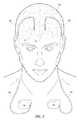
- FIG. 2illustrates a typical deep brain stimulation system implanted in a patient
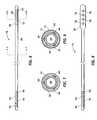
- FIG. 3is an isometric view of the distal end of the lead shown in FIG. 2 ;
- FIG. 4is an isometric view of the distal end of the extension shown in FIG. 2 ;
- FIG. 5is an isometric view of an example of a connector screw block suitable for connecting the lead of FIG. 3 to the extension shown in FIG. 4 ;
- FIG. 6is a top view of the lead shown in FIG. 2 ;
- FIGS. 7 and 8are cross-sectional views taken along lines 7 - 7 and 8 - 8 , respectively, in FIG. 6 ;
- FIG. 9is a top view of an alternate lead configuration
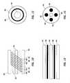
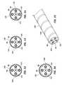
- FIGS. 10 and 11are longitudinal and radial cross-sectional views, respectively, of a helically wound lead of the type shown in FIG. 6 ;
- FIGS. 12 and 13are longitudinal and radial cross-sectional views, respectively, of a cabled lead
- FIG. 14is an exploded view of a neurostimulation system
- FIG. 15is a cross-sectional view of the extension shown in FIG. 14 taken along line 15 - 15 ;
- FIGS. 16-19are schematic diagrams of potential lossy lead configurations
- FIGS. 20 and 21are longitudinal and cross-sectional views, respectively, of a first embodiment of the inventive lead
- FIGS. 22 and 23are longitudinal and cross-sectional views, respectively, of a further embodiment of the present invention.
- FIGS. 24-30illustrate still further embodiments of the present invention.
- FIGS. 31-34are isometric and cross-sectional views illustrating a still further embodiment of the present invention.
- FIGS. 35 and 36are isometric and cross-sectional views, respectively, of yet another embodiment of the present invention.
- FIGS. 37 and 38illustrate still further embodiments of the present invention.
- FIG. 39is an isometric view of yet another embodiment of the present invention.
- fileralso spelled “filar” is intended in its broadest sense to denote a conductor of the type carried by an implantable medical lead.
- FIG. 1illustrates a typical SCS system implanted in a patient.
- the systemcomprises a pulse generator such as a SCS neurostimulator 20 , a lead extension 22 having a proximal end coupled to neurostimulator 20 as will be more fully described below, and a lead 24 having a proximal end coupled to the distal end of extension 22 and having a distal end coupled to one or more electrodes 26 .
- Lead extension 22is connected to lead 24 by way of a connector 32 .
- Neurostimulator 20is typically placed in the abdomen of a patient 28 , and lead 24 is placed somewhere along spinal cord 30 . As stated previously, neurostimulator 20 may have one or two leads each having four to eight electrodes.
- Neurostimulator 20may be considered to be an implantable pulse generator of the type available from Medtronic, Inc. and capable of generating multiple pulses occurring either simultaneously or one pulse shifting in time with respect to the other, and having independently varying amplitudes and pulse widths.
- Neurostimulator 20contains a power source and the electronics for sending precise, electrical pulses to the spinal cord to provide the desired treatment therapy. While neurostimulator 20 typically provides electrical stimulation by way of pulses, other forms of stimulation may be used such as continuous electrical stimulation.
- Lead 24is a small medical wire having special insulation thereon and includes one or more insulated electrical conductors each coupled at their proximal end to a connector and to contacts/electrodes 26 at its distal end. Some leads are designed to be inserted into a patient percutaneously (e.g. the Model 3487A Pisces—Quad® lead available from Medtronic, Inc.), and some are designed to be surgically implanted (e.g. Model 3998 Specify® lead, also available from Medtronic, Inc.). Lead 24 may contain a paddle at its distant end for housing electrodes 26 ; e.g. a Medtronic paddle having model number 3587A. Alternatively, electrodes 26 may comprise one or more ring contacts at the distal end of lead 24 as will be more fully described below.
- Electrodes 26may comprise one or more ring contacts at the distal end of lead 24 as will be more fully described below.
- lead 24is shown as being implanted in position to stimulate a specific site in spinal cord 30 , it could also be positioned along the peripheral nerve or adjacent neural tissue ganglia or may be positioned to stimulate muscle tissue. Furthermore, electrodes/contacts 26 may be epidural, intrathecal or placed into spinal cord 30 itself. Effective spinal cord stimulation may be achieved by any of these lead placements. While the lead connector at proximal end of lead 24 may be coupled directly to neurostimulator 20 , the lead connector is typically coupled to lead extension 22 as is shown in FIG. 1 . An example of a lead extension is Model 7495 available from Medtronic, Inc.
- a physician's programmerutilizes telemetry to communicate with the implanted neurostimulator 20 to enable the physician to program and manage a patient's therapy and troubleshoot the system.
- a typical physician's programmeris available from Medtronic, Inc. and bears Model No. 7432.
- a patient's programmeralso not shown also uses telemetry to communicate with neurostimulator 20 so as to enable the patient to manage some aspects of their own therapy as defined by the physician.
- An example of a patient programmeris Model 7434 Itrel® 3 EZ Patient Programmer available from Medtronic, Inc.
- Implantation of a neurostimulatortypically begins with the implantation of at least one stimulation lead while the patient is under a local anesthetic. While there are many spinal cord lead designs utilized with a number of different implantation techniques, the largest distinction between leads revolves around how they are implanted. For example, surgical leads have been shown to be highly effective, but require a laminectomy for implantation. Percutaneous leads can be introduced through a needle, a much easier procedure. To simplify the following explanation, discussion will focus on percutaneous lead designs, although it will be understood by those skilled in the art that the inventive aspects are equally applicable to surgical leads.
- the lead's distal endis typically anchored to minimize movement of the lead after implantation.
- the lead's proximal endis typically configured to connect to a lead extension 22 . The proximal end of the lead extension is then connected to the neurostimulator 20 .
- FIG. 2illustrates a DBS system implanted in a patient 40 and comprises substantially the same components as does an SCS; that is, at least one neurostimulator, at least one extension, and at least one stimulation lead containing one or more electrodes.
- each neurostimulator 42is implanted in the pectoral region of patient 40 .
- Extensions 44are deployed up through the patient's neck, and leads 46 are implanted in the patient's brain as is shown at 43 .
- each of leads 46is connected to its respective extension 44 just above the ear on both sides of patient 40 .
- FIG. 3is an isometric view of the distal end of lead 46 having a distal tip 49 .
- four ring electrodes 48are positioned on the distal end of lead 46 and coupled to internal conductors or filers (not shown) contained within lead 46 .
- internal conductors or filersnot shown
- FIG. 4is an isometric view of the distal end of extension 44 , which includes a connector portion 45 having four internal contacts 47 .
- the proximal end of the DBS leadplugs into distal connector portion 45 of extension 44 and is held in place by means of, for example, a plurality (e.g. four) of set screws 50 .
- This conceptis generally illustrated in FIG. 5 , which shows a proximal end of lead 46 including one or more (e.g., four) proximal electrical ring contacts 51 (only one of which is shown in FIG. 5 ) being received within an opening 52 provided in a generalized set screw block 54 .
- extension 44is secured to neurostimulator 42 as is shown in FIGS. 1 and 2 .
- FIG. 6is a top view of lead 46 shown in FIG. 2 .
- FIGS. 7 and 8are cross-sectional views taken along lines 7 - 7 and 8 - 8 , respectively, in FIG. 6 .
- Distal end 60 of lead 46includes at least one electrode 62 (four are shown). As stated previously, up to eight electrodes may be utilized.
- Each of electrodes 62is preferably constructed as is shown in FIG. 8 . That is, electrode 62 may comprise a conductive ring 71 on the outer surface of the elongate tubing making up distal shaft 60 .
- Each electrode 62is electrically coupled to a longitudinal wire 66 (shown in FIGS. 7 and 8 ) which extends to a contact 64 at the proximal end of lead 46 .
- Longitudinal wires 66may be of a variety of configurations; e.g. discreet wires, printed circuit conductors, etc. From the arrangement shown in FIG. 6 , it should be clear that four conductors or filers run through the body of lead 46 to electrically connect the proximal electrodes 64 to the distal electrodes 62 . As will be further discussed below, the longitudinal conductors 66 may be spirally configured along the axis of lead 46 until they reach the connector contacts.
- the shaft of lead 46preferably has a lumen 68 extending therethrough for receiving a stylet that adds a measure of rigidity during installation of the lead.
- the shaftpreferably comprises a comparatively stiffer inner tubing member 70 (e.g. a polyamine, polyamide, high density polyethylene, polypropylene, polycarbonate or the like). Polyamide polymers are preferred.
- the shaftpreferably includes a comparatively softer outer tubing member or jacket 72 ; e.g. silicon or other suitable elastomeric polymer.
- the conductive rings 71are preferably of a biocompatible metal such as one selected from the noble group of metals, preferably palladium, platinum or gold and their alloys.
- FIG. 9illustrates an alternative lead 74 wherein distal end 76 is broader (e.g. paddle-shaped) to support a plurality of distal electrodes 78 .
- a lead of this typeis shown in FIG. 1 .
- distal electrodes 78are coupled to contacts 64 each respectively by means of an internal conductor or filer.
- a more detailed description of the leads shown in the FIGS. 6 and 9may be found in U.S. Pat. No. 6,529,774 issued Mar. 4, 2003 and entitled “Extradural Leads, Neurostimulator Assemblies, and Processes of Using Them for Somatosensory and Brain Stimulation”.
- FIGS. 10 and 11are longitudinal and radial cross-sectional views, respectively, of a helically wound lead of the type shown in FIG. 6 .
- the leadcomprises an outer lead body or jacket 80 ; a plurality of helically wound, co-radial lead filers 82 ; and a stylet lumen 84 .
- a styletis a stiff, formable insert placed in the lead during implant so as to enable the physician to steer the lead to an appropriate location.
- FIG. 10illustrates four separate, co-radially wound filers 86 , 88 , 90 and 92 which are electrically insulated from each other and electrically couple a single electrode 62 ( FIG. 6 ) to a single contact 64 ( FIG. 6 ).
- the lead filers 82have a specific pitch and form a helix of a specific diameter.
- the helix diameteris relevant in determining the inductance of the lead.
- These filers themselvesalso have a specific diameter and are made of a specific material.
- the filer diameter, material, pitch and helix diameterare relevant in determining the impedance of the lead.
- the inductancecontributes to a frequency dependent impedance.
- FIGS. 12 and 13are longitudinal and radially cross-sectional views, respectively, of a cabled lead.
- the leadcomprises outer lead body or jacket 94 , stylet lumen 96 , and a plurality (e.g. four, eight, etc.) of straight lead filers 98 .
- FIG. 14is an exploded view of a neurostimulation system that includes an extension 100 configured to be coupled between a neurostimulator 102 and lead 104 .
- the proximal portion of extension 100comprises a connector 106 configured to be received or plugged into connector block 109 of neurostimulator 102 .
- the distal end of extension 100likewise comprises a connector 110 including internal contacts 111 configured to receive the proximal end of lead 104 having contacts 112 thereon.
- the distal end of lead 104includes distal electrodes 114 .
- FIG. 15is a cross-sectional view of extension 100 .
- Lead extension 100has a typical diameter of 0.1 inch, which is significantly larger than that of lead 104 so as to make extension 100 more durable than lead 104 .
- Extension 100differs from lead 104 also in that each filer 106 in lead body 100 is helically wound or coiled in its own lumen 108 and not co-radially wound with the rest of the filers as was the case in lead 104 .
- the diameter of typical percutaneous leadsis approximately 0.05 inch. This diameter is based upon the diameter of the needle utilized in the surgical procedure to deploy the lead and upon other clinical anatomical requirements.
- the length of such percutaneous SCS leadsis based upon other clinical anatomical requirements.
- the length of such percutaneous SCS leadsis typically 28 centimeters; however, other lengths are utilized to meet particular needs of specific patients and to accommodate special implant locations.
- Lead lengthis an important factor in determining the suitability of using the lead in an MRI environment. For example, the greater length of the lead, the larger the effective loop area that is impacted by the electromagnetic field (i.e. the longer the lead, the larger the antenna). Furthermore, depending on the lead length, there can be standing wave effects that create areas of high current along the lead body. This can be problematic if the areas of high current are near the distal electrodes.
- the cable leadhas a smaller DC resistance because the length of the straight filer is less than that of a coiled filer and the impedance at high frequency is reduced because the inductance has been significantly reduced. It has been determined that the newer cabled filer designs tend to be more problematic in an MRI environment than do the wound helix filer designs. It should be noted that straight filers for cable leads sometimes comprise braided stranded wire that includes a number of smaller strands woven to make up each filer. This being the case, the number of strands could be varied to alter the impedance.
- the resistance R of a lead fileris governed by the equation:
- RL ⁇ ⁇ ⁇ a Equation ⁇ ⁇ ( 1 )
- Ris the resistance
- Lis the length of the filer
- ⁇is the conductivity
- ais the cross-sectional area. Decreasing the conductivity and/or the cross-sectional area of the filer will increase resistance proportionally.
- One typical leadutilizes a chromium-cobalt (non-cored MP35N) filer having a conductivity of 1.1 ⁇ 10 6 mhos/meter, a diameter of approximately 0.005 inch, and a length of approximately 100 centimeters.
- the resistance R of the leadis approximately twenty ohms. If the diameter were reduced to 0.002 inch, R could be increased to approximately 710 ohms (or approximately 126 ohms for a 28 centimeter lead).
- the lead body or lead jacketis configured to shunt induced RF energy from the filers to the patient's body along the length of the lead (or at least a portion thereof). That is, the lead body or lead jacket itself acts as a distributed shunt from the conductive lead filers to the patient's body during an MRI scan. This may be accomplished by (1) providing a shunt conductance (i.e. a DC path) between a filer and a patient's body creating a current path regardless of frequency; (2) a shunt capacitance (i.e. an AC current path) that allows current to flow at high frequency (i.e.
- a shunt conductancei.e. a DC path
- a shunt capacitancei.e. an AC current path
- FIGS. 16-19are schematic diagrams illustrating how the lossy jacket may be configured. If a filer is represented by conductor 81 and a patient's body is represented by a grounded conductor 83 , FIG. 16 illustrates a capacitive shunt 85 in parallel with a conductive shunt 87 . In FIG. 17 , the shunt is comprised of the series combination of resistor 89 and capacitor 91 . In FIG. 18 , the shunt comprises the parallel combination of capacitor 93 and resistor 95 in series with resistor 97 , and in FIG.
- series resistor 97is replaced by a series capacitor 99 .
- This approachis equally applicable to the extension 100 described above in connection with FIGS. 14 and 15 .
- the term “lead” as hereinafter usedis intended to include such lead extensions.
- the resistance of the DC pathit is recommended that the resistance of the DC path be at least ten times that of the stimulation path.
- FIG. 20is a longitudinal view of a first exemplary embodiment of the inventive medical lead illustrating a partially exploded portion of lead jacket 120 .
- FIG. 21is a cross-sectional view of the lead shown in FIG. 20 taken along line 21 - 21 .
- the lead shown in FIGS. 20 and 21is substantially similar to that shown in FIGS. 12 and 13 respectively and therefore like reference numerals denote like elements.
- Straight filers 98 shown in FIG. 21are each provided with protective insulation 121 (e.g. Teflon), and jacket 120 may be made from materials such as silicone, polyether urethane, etc.
- protective insulation 121e.g. Teflon
- the jacket materialmay be doped with a dielectric material such as carbon, talc, and minerals such as calcium carbonate, titanium dioxide, aluminum dioxide, sapphire, mica, and silica. Both pyrolitic and vitreous carbon would be suitable.
- the dopantshould be biocompatible and preferably have a dielectric constant greater than five. Both the type and concentration of dopant is selected to obtain the desired frequency response in accordance with known techniques.
- the dopantis represented graphically in FIGS. 20 and 21 as particles 122 . These particles form tiny capacitors with each other and with the conductive filers so as to conduct induced RF energy at high frequencies from filers 98 to body tissue or fluids.
- the doping concentrationmay be uniform or non-uniform along the length of the lead. For example, only certain portions of the lead might be doped; e.g. the distal end of the lead close to the stimulation electrode so as to create a different characteristic impedance than the rest of the lead. Alternatively, the dopant concentration may vary along the length of the lead. This change in characteristic impedance could create a reflection at high frequencies so as to keep induced RF energy away from the stimulation electrode.
- the lead body or jacketmay be provided with a plurality of pores 124 shown in FIGS. 22 and 23 , which are longitudinal and cross-sectional views, respectively.
- Pores 124(produced by means of, for example, laser drilling) permit body fluid to enter the lead and create a larger capacitance between the patient's body and lead filers 98 . This larger capacitance at higher frequency would enhance the conduction of induced RF energy from filers 98 to the patient's body.
- pores 124may be placed anywhere along the length of the lead (e.g. close to the stimulation electrodes) or the pore density may be varied along the length of the lead. If desired, the jacket may be doped in addition to being provided with pores 124 .
- the dopant and/or poresmay be concentrated in a longitudinal path limited to one or more selected circumferential sectors as is shown in FIGS. 24 and 25 , respectively, or the concentration of dopant may be varied circumferentially.
- concentrations of dopant and porescan vary both longitudinally and circumferentially.
- one or more conductive strips 125may be disposed longitudinally along the length of the lead (or a portion thereof) as is shown in FIG. 26 .
- the jacket materialmay be varied along the length of the lead to provide different lossy conduction at different locations.
- sheath 120may be comprised of alternating sections 127 and 129 of dielectric (e.g. urethane) and conductive sections (e.g. titanium, platinum, stainless steel, conductive polymers, chromium-cobalt alloys, etc.), respectively.
- Yet another embodiment of the present inventioncomprises a multi-layered jacket of the type shown in FIG. 28 including, for example, alternating layers 131 and 133 of dielectric and conductive material, respectively; e.g. alternating layers of TeflonTM impregnated to be conductive or non-conductive.
- the alternating layersmay be produced by, for example, co-extrusion, dispersion, coating, vapor deposition or atomized coating in accordance with known techniques; or alternatively, the lead jacket could be wrapped with alternating conductive and non-conductive layers to create a shunt capacitance. This could be done using two conductive layers (e.g. doped TeflonTM or PTFE) and one dielectric layer (e.g.
- FIGS. 29 and 30PTFE doped with a dielectric material as is shown in FIGS. 29 and 30 .
- Layerscould be, for example, extruded or wrapped. Preferably, the two conductive layers are wrapped and the intermediate non-conductive layer is extruded. In FIG. 29 , the layers 135 are wrapped in an edge-abutting manner, whereas in FIG. 30 , the layers are wrapped in an overlapping manner as indicated by dotted line 137 .
- FIG. 39illustrates a medical lead comprised of a plurality of filers jacketed as described above and bundled as, for example, by adhering or otherwise securing the jacketed filers.
- FIGS. 31-36illustrate yet another exemplary embodiment of the inventive lead incorporating a helical coil of wire that forms a continuous first plate of a capacitor, the second plate being each of the conductive filers 98 .
- Thisincreases the capacitance to the patient's body to shunt induced RF energy to the patient's body at MRI frequencies.
- Helical coil 126may take the form of a flat ribbon and may be imbedded in lead jacket 120 as is shown in FIGS. 31 and 32 which are isometric and cross-sectional views respectively. It is known that
- C⁇ ⁇ ⁇ A d Equation ⁇ ⁇ ( 2 )
- Athe area of the capacitor plates
- dthe distance between the plates
- ⁇the dielectric constant of the material between them. It can be seen that the capacitance increases with area. Thus, the use of a flat ribbon coil will increase the capacitance. It should also be apparent that the smaller the distance between coil 126 and filers 98 , the greater the capacitance between them. Thus, the lead may be constructed so as to place filers 98 closer to jacket 120 . Additionally, the capacitance will increase if the jacket is made of a material having a higher dielectric constant.
- jacket 120may be provided with a plurality of pores 124 to expose coil 126 to body tissue.
- coil 126may be placed on the inner surface of jacket 120 as is shown in FIG. 34 in order to reduce the distance between coil 126 and filers 98 .
- Jacket 120may be doped with a conductive material or provided with pores in order to increase the capacitance as described above.
- coil 126may be positioned on or imbedded within an outer surface of jacket 120 as is shown in FIGS. 35 and 36 which are isometric and cross-sectional views, respectively.
- FIG. 37is a cross-sectional view of yet another exemplary embodiment of the present invention.
- the region between the insulated filers and the interior surface of jacket 120is filled with a material 130 (preferably having a dielectric constant greater than three) that creates a capacitance with conductive filers 98 .
- a material 130preferably having a dielectric constant greater than three
- the conductive gelcould fill only selected portions along the length of the lead.
- the entire lead jacket 120may be made of a flexible biocompatible conductive material.
- FIG. 38illustrates yet another embodiment of the present invention.
- the entire lead jacketcould be removed (i.e. the lead is manufactured without a lead jacket) or no lead jacket is placed around selected portions of the lead as is shown at 132 .
- the individual filersare separated from each other and from the patient's body tissue or fluids by the insulation 121 on each of the conductive filers. Certain areas of the lead that are most prone to damage could be provided with a lead jacket while other portions of the lead are jacket-free.
- a leadmay be provided with a jacket that could be retracted or removed after the lead has been implanted. This provides for good handling and steerability while maximizing its lossy characteristics along the length of the lead.
Landscapes
- Health & Medical Sciences (AREA)
- Neurology (AREA)
- Neurosurgery (AREA)
- General Health & Medical Sciences (AREA)
- Life Sciences & Earth Sciences (AREA)
- Heart & Thoracic Surgery (AREA)
- Engineering & Computer Science (AREA)
- Biomedical Technology (AREA)
- Nuclear Medicine, Radiotherapy & Molecular Imaging (AREA)
- Radiology & Medical Imaging (AREA)
- Veterinary Medicine (AREA)
- Animal Behavior & Ethology (AREA)
- Public Health (AREA)
- Cardiology (AREA)
- Psychology (AREA)
- Orthopedic Medicine & Surgery (AREA)
- Electrotherapy Devices (AREA)
Abstract
Description
This application claims the benefit of U.S. Provisional Application No. 60/557,991 filed Mar. 30, 2004.
The present invention generally relates to implantable medical devices, and more particularly to an implantable MRI-safe lead including a conductive jacket for dissipating or directing induced RF energy to a patient's body so as to reduce the generation of unwanted heat at the lead's stimulation electrodes.
Implantable medical devices are commonly used today to treat patients suffering from various ailments. Such implantable devices may be utilized to treat conditions such as pain, incontinence, sleep disorders, and movement disorders such as Parkinson's disease and epilepsy. Such therapies also appear promising in the treatment of a variety of psychological, emotional, and other physiological conditions.
One known type of implantable medical device, a neurostimulator, delivers mild electrical impulses to neural tissue using an electrical lead. For example, to treat pain, electrical impulses may be directed to specific sites. Such neurostimulation may result in effective pain relief and a reduction in the use of pain medications and/or repeat surgeries.
Typically, such devices are totally implantable and may be controlled by a physician or a patient through the use of an external programmer. Current systems generally include a non-rechargeable primary cell neurostimulator, a lead extension, and a stimulation lead, and the two main classes of systems may be referred to as: (1) Spinal Cord Stimulation (SCS) and (2) Deep Brain Stimulation (DBS).
An SCS stimulator may be implanted in the abdomen, upper buttock, or pectoral region of a patient and may include at least one extension running from the neurostimulator to the lead or leads which are placed somewhere along the spinal cord. Each of the leads (to be discussed in detail hereinbelow) currently contains from one to eight electrodes. Each extension (likewise to be discussed in detail below) is plugged into or connected to the neurostimulator at a proximal end thereof and is coupled to and interfaces with the lead or leads at a distal end of the extension or extensions.
The implanted neurostimulation system is configured to send mild electrical pulses to the spinal cord. These electrical pulses are delivered through the lead or leads to regions near the spinal cord or the nerve selected for stimulation. Each lead includes a small insulated wire coupled to an electrode at the distal end thereof through which the electrical stimulation is delivered. Typically, the lead also comprises a corresponding number of internal wires to provide separate electrical connection to each electrode such that each electrode may be selectively used to provide stimulation. Connection of the lead to an extension may be accomplished by means of a connector block including, for example, a series or combination of set-screws, ball-seals, etc. The leads are inserted into metal set screw blocks, and metal set screws are manipulated to press the contacts against the blocks to clamp them in place and provide an electrical connection between the lead wires and the blocks. Such an arrangement is shown in U.S. Pat. No. 5,458,629 issued Oct. 17, 1995 and entitled “Implantable Lead Ring Electrode and Method of Making”.
A DBS system comprises similar components (i.e. a neurostimulator, at least one extension, and at least one stimulation lead) and may be utilized to provide a variety of different types of electrical stimulation to reduce the occurrence or effects of Parkinson's disease, epileptic seizures, or other undesirable neurological events. In this case, the neurostimulator may be implanted into the pectoral region of the patient. The extension or extensions may extend up through the patient's neck, and the leads/electrodes are implanted in the brain. The leads may interface with the extension just above the ear on both sides of the patient. The distal end of the lead may contain from four to eight electrodes and, as was the case previously, the proximal end of the lead may connect to the distal end of the extension and held in place by set screws. The proximal portion of the extension plugs into the connector block of the neurostimulator.
Magnetic resonance imaging (MRI) is a relatively new and efficient technique that may be used in the diagnosis of many neurological disorders. It is an anatomical imaging tool which utilizes non-ionizing radiation (i.e. no x-rays or gamma rays) and provides a non-invasive method for the examination of internal structure and function. For example, MRI permits the study of the overall function of the heart in three dimensions significantly better than any other imaging method. Furthermore, imaging with tagging permits the non-invasive study of regional ventricular function.
MRI scanning is widely used in the diagnosis of diseases and injuries to the head. In fact, the MRI is now considered by many to be the preferred standard of care, and failure to prescribe MRI scanning can be considered questionable. For example, approximately sixteen million MRIs were performed in 1996 followed by approximately twenty million in the year 2000. It is projected that forty million MRIs will be performed in 2004.
In an MRI scanner, a magnet creates a strong magnetic field which aligns the protons of hydrogen atoms in the body and then exposes them to radio frequency (RF) energy from a transmitter portion of the scanner. This spins the various protons, and they produce a faint signal that is detected by a receiver portion of the scanner. A computer renders these signals into an image. During this process, three electromagnetic fields are produced; i.e. (1) a static magnetic field, (2) a gradient magnetic field, and (3) a radio frequency (RF) field. The main or static magnetic field may typically vary between 0.2 and 3.0 Tesla. A nominal value of 1.5 Tesla is approximately equal to 15,000 Gauss which is 30,000 times greater than the Earth's magnetic field of approximately 0.5 Gauss. The time varying or gradient magnetic field may have a maximum strength of approximately 40 milli-Tesla/meter at a frequency of 0-5 KHz. The RF may, for example, produce thousands of watts at frequencies of between 8-128 MHz. For example, up to 20,000 watts may be produced at 64 MHz and a static magnetic field of 1.5 Tesla; that is, 20 times more power than a typical toaster. Thus, questions have arisen regarding the potential risk associated with undesirable interaction between the MRI environment and the above-described neurostimulation systems; e.g. forces and torque on the implantable device within the MRI scanner caused by the static magnetic field, RF-induced heating, induced currents due to gradient magnetic fields, device damage, and image distortion. Of these interactions, the problems associated with induced RF currents in the leads are most deserving of attention since it has been found that the temperature in the leads can rise by as much as 25° Centigrade or higher in an MRI environment.
Accordingly, it would be desirable to provide an implantable medical device that may be safely operated in an MRI environment. It would be further desirable to provide an implantable medical device such as a SCS or DBS neurostimulation system that may be operated in an MRI environment without the generation of significant heat in the leads due to induced RF currents. It would be still further desirable to provide an MRI-safe, implantable lead that may be used in conjunction with known medical devices that dissipates or directs induced RF energy to a patient's body so as to reduce the generation of unwanted heat at the lead's stimulation electrodes. Other desirable features and characteristics of the present invention will become apparent from the subsequent detailed description of the invention and the appended claims, taken in conjunction with the accompanying drawings and this background of the invention.
According to an aspect of the invention, there is provided a medical lead configured to be implanted into a patient's body and having at least one distal stimulation electrode and at least one conductive filer electrically coupled to the distal stimulation electrode. A jacket is provided for housing the conductive filer and for providing a path distributed along at least a portion of the length of the lead for guiding induced RF energy from the filer to the patient's body.
The present invention will hereinafter be described in conjunction with the accompanying drawing, wherein like reference numerals denote like elements; and
The following detailed description of the invention is merely exemplary in nature and is not intended to limit the invention or the application and uses of the invention. Furthermore, there is no intention to be bound by any theory presented in the preceding background of the invention or the following detailed description of the invention. As appearing herein, the term ‘filer’ (also spelled “filar”) is intended in its broadest sense to denote a conductor of the type carried by an implantable medical lead.
Whilelead 24 is shown as being implanted in position to stimulate a specific site inspinal cord 30, it could also be positioned along the peripheral nerve or adjacent neural tissue ganglia or may be positioned to stimulate muscle tissue. Furthermore, electrodes/contacts 26 may be epidural, intrathecal or placed intospinal cord 30 itself. Effective spinal cord stimulation may be achieved by any of these lead placements. While the lead connector at proximal end oflead 24 may be coupled directly toneurostimulator 20, the lead connector is typically coupled to lead extension22 as is shown inFIG. 1 . An example of a lead extension is Model 7495 available from Medtronic, Inc.
A physician's programmer (not shown) utilizes telemetry to communicate with the implantedneurostimulator 20 to enable the physician to program and manage a patient's therapy and troubleshoot the system. A typical physician's programmer is available from Medtronic, Inc. and bears Model No. 7432. Similarly, a patient's programmer (also not shown) also uses telemetry to communicate withneurostimulator 20 so as to enable the patient to manage some aspects of their own therapy as defined by the physician. An example of a patient programmer is Model 7434 Itrel® 3 EZ Patient Programmer available from Medtronic, Inc.
Implantation of a neurostimulator typically begins with the implantation of at least one stimulation lead while the patient is under a local anesthetic. While there are many spinal cord lead designs utilized with a number of different implantation techniques, the largest distinction between leads revolves around how they are implanted. For example, surgical leads have been shown to be highly effective, but require a laminectomy for implantation. Percutaneous leads can be introduced through a needle, a much easier procedure. To simplify the following explanation, discussion will focus on percutaneous lead designs, although it will be understood by those skilled in the art that the inventive aspects are equally applicable to surgical leads. After the lead is implanted and positioned, the lead's distal end is typically anchored to minimize movement of the lead after implantation. The lead's proximal end is typically configured to connect to a lead extension22. The proximal end of the lead extension is then connected to theneurostimulator 20.
The shaft oflead 46 preferably has alumen 68 extending therethrough for receiving a stylet that adds a measure of rigidity during installation of the lead. The shaft preferably comprises a comparatively stiffer inner tubing member70 (e.g. a polyamine, polyamide, high density polyethylene, polypropylene, polycarbonate or the like). Polyamide polymers are preferred. The shaft preferably includes a comparatively softer outer tubing member orjacket 72; e.g. silicon or other suitable elastomeric polymer. The conductive rings71 are preferably of a biocompatible metal such as one selected from the noble group of metals, preferably palladium, platinum or gold and their alloys.
Leads of the type described above may be of the wound helix filer type or of the cabled filer type.FIGS. 10 and 11 are longitudinal and radial cross-sectional views, respectively, of a helically wound lead of the type shown inFIG. 6 . The lead comprises an outer lead body orjacket 80; a plurality of helically wound,co-radial lead filers 82; and astylet lumen 84. As stated previously, a stylet is a stiff, formable insert placed in the lead during implant so as to enable the physician to steer the lead to an appropriate location.FIG. 10 illustrates four separate,co-radially wound filers FIG. 6 ) to a single contact64 (FIG. 6 ).
As can be seen, thelead filers 82 have a specific pitch and form a helix of a specific diameter. The helix diameter is relevant in determining the inductance of the lead. These filers themselves also have a specific diameter and are made of a specific material. The filer diameter, material, pitch and helix diameter are relevant in determining the impedance of the lead. In the case of a helically wound lead, the inductance contributes to a frequency dependent impedance.FIGS. 12 and 13 are longitudinal and radially cross-sectional views, respectively, of a cabled lead. The lead comprises outer lead body orjacket 94,stylet lumen 96, and a plurality (e.g. four, eight, etc.) ofstraight lead filers 98.
The diameter of typical percutaneous leads is approximately 0.05 inch. This diameter is based upon the diameter of the needle utilized in the surgical procedure to deploy the lead and upon other clinical anatomical requirements. The length of such percutaneous SCS leads is based upon other clinical anatomical requirements. The length of such percutaneous SCS leads is typically 28 centimeters; however, other lengths are utilized to meet particular needs of specific patients and to accommodate special implant locations.
Lead length is an important factor in determining the suitability of using the lead in an MRI environment. For example, the greater length of the lead, the larger the effective loop area that is impacted by the electromagnetic field (i.e. the longer the lead, the larger the antenna). Furthermore, depending on the lead length, there can be standing wave effects that create areas of high current along the lead body. This can be problematic if the areas of high current are near the distal electrodes.
Compared to the helically wound lead, the cable lead has a smaller DC resistance because the length of the straight filer is less than that of a coiled filer and the impedance at high frequency is reduced because the inductance has been significantly reduced. It has been determined that the newer cabled filer designs tend to be more problematic in an MRI environment than do the wound helix filer designs. It should be noted that straight filers for cable leads sometimes comprise braided stranded wire that includes a number of smaller strands woven to make up each filer. This being the case, the number of strands could be varied to alter the impedance.
It has been discovered that high lead impedances at MRI operational frequencies can reduce the heating of an electrode during an MRI procedure. The high impedance acts as a choke for current flowing through the lead and increases real losses along the length of the lead. These two mechanisms reduce electrode heating. As previously alluded to, leads have been intentionally designed with low impedance to enhance system stimulation efficiency. Thus, the simplest way to increase the impedance of a lead is to increase its DC resistance.
For example, the resistance R of a lead filer is governed by the equation:
where R is the resistance, L is the length of the filer, σ is the conductivity, and a is the cross-sectional area. Decreasing the conductivity and/or the cross-sectional area of the filer will increase resistance proportionally. One typical lead utilizes a chromium-cobalt (non-cored MP35N) filer having a conductivity of 1.1×10⁶mhos/meter, a diameter of approximately 0.005 inch, and a length of approximately 100 centimeters. Using Equation (1), the resistance R of the lead is approximately twenty ohms. If the diameter were reduced to 0.002 inch, R could be increased to approximately 710 ohms (or approximately 126 ohms for a 28 centimeter lead).
Described below in connection withFIG. 16 is a lead wherein the lead body or lead jacket is configured to shunt induced RF energy from the filers to the patient's body along the length of the lead (or at least a portion thereof). That is, the lead body or lead jacket itself acts as a distributed shunt from the conductive lead filers to the patient's body during an MRI scan. This may be accomplished by (1) providing a shunt conductance (i.e. a DC path) between a filer and a patient's body creating a current path regardless of frequency; (2) a shunt capacitance (i.e. an AC current path) that allows current to flow at high frequency (i.e. MRI frequencies and not stimulation frequencies); or (3) a combination of a shunt conductance and a shunt capacitance. Each of these three mechanisms will create a lossy lead. For example,FIGS. 16-19 are schematic diagrams illustrating how the lossy jacket may be configured. If a filer is represented byconductor 81 and a patient's body is represented by a groundedconductor 83,FIG. 16 illustrates acapacitive shunt 85 in parallel with aconductive shunt 87. InFIG. 17 , the shunt is comprised of the series combination ofresistor 89 andcapacitor 91. InFIG. 18 , the shunt comprises the parallel combination ofcapacitor 93 andresistor 95 in series withresistor 97, and inFIG. 19 ,series resistor 97 is replaced by aseries capacitor 99. This approach is equally applicable to theextension 100 described above in connection withFIGS. 14 and 15 . Thus, the term “lead” as hereinafter used is intended to include such lead extensions. In the case of a DC current path, it is recommended that the resistance of the DC path be at least ten times that of the stimulation path.
In order to produce alead jacket 120 that acts as a shunt at high frequency along the length thereof, the jacket material may be doped with a dielectric material such as carbon, talc, and minerals such as calcium carbonate, titanium dioxide, aluminum dioxide, sapphire, mica, and silica. Both pyrolitic and vitreous carbon would be suitable. In any case, the dopant should be biocompatible and preferably have a dielectric constant greater than five. Both the type and concentration of dopant is selected to obtain the desired frequency response in accordance with known techniques.
The dopant is represented graphically inFIGS. 20 and 21 asparticles 122. These particles form tiny capacitors with each other and with the conductive filers so as to conduct induced RF energy at high frequencies fromfilers 98 to body tissue or fluids. The doping concentration may be uniform or non-uniform along the length of the lead. For example, only certain portions of the lead might be doped; e.g. the distal end of the lead close to the stimulation electrode so as to create a different characteristic impedance than the rest of the lead. Alternatively, the dopant concentration may vary along the length of the lead. This change in characteristic impedance could create a reflection at high frequencies so as to keep induced RF energy away from the stimulation electrode.
In accordance with a second exemplary embodiment of the inventive lead, the lead body or jacket may be provided with a plurality ofpores 124 shown inFIGS. 22 and 23 , which are longitudinal and cross-sectional views, respectively. Pores124 (produced by means of, for example, laser drilling) permit body fluid to enter the lead and create a larger capacitance between the patient's body and leadfilers 98. This larger capacitance at higher frequency would enhance the conduction of induced RF energy fromfilers 98 to the patient's body. As was the case previously in connection with the doped jacket ofFIGS. 20 and 21 , pores124 may be placed anywhere along the length of the lead (e.g. close to the stimulation electrodes) or the pore density may be varied along the length of the lead. If desired, the jacket may be doped in addition to being provided withpores 124.
In another embodiment, the dopant and/or pores may be concentrated in a longitudinal path limited to one or more selected circumferential sectors as is shown inFIGS. 24 and 25 , respectively, or the concentration of dopant may be varied circumferentially. Thus, the concentrations of dopant and pores can vary both longitudinally and circumferentially. If desired, one or moreconductive strips 125 may be disposed longitudinally along the length of the lead (or a portion thereof) as is shown inFIG. 26 . Still alternatively, the jacket material may be varied along the length of the lead to provide different lossy conduction at different locations. For example, inFIG. 27 ,sheath 120 may be comprised of alternatingsections
Yet another embodiment of the present invention comprises a multi-layered jacket of the type shown inFIG. 28 including, for example, alternatinglayers FIGS. 29 and 30 . Layers could be, for example, extruded or wrapped. Preferably, the two conductive layers are wrapped and the intermediate non-conductive layer is extruded. InFIG. 29 , thelayers 135 are wrapped in an edge-abutting manner, whereas inFIG. 30 , the layers are wrapped in an overlapping manner as indicated bydotted line 137. These techniques are equally applicable to the filer itself, insuring that there is no conduction from filer-to-filer and creating a capacitance around the filer that conducts at high frequency. For example,FIG. 39 illustrates a medical lead comprised of a plurality of filers jacketed as described above and bundled as, for example, by adhering or otherwise securing the jacketed filers.
where C is the capacitance, A is the area of the capacitor plates, d is the distance between the plates and ∈ is the dielectric constant of the material between them. It can be seen that the capacitance increases with area. Thus, the use of a flat ribbon coil will increase the capacitance. It should also be apparent that the smaller the distance between
If desired,jacket 120 may be provided with a plurality ofpores 124 to exposecoil 126 to body tissue. In addition,coil 126 may be placed on the inner surface ofjacket 120 as is shown inFIG. 34 in order to reduce the distance betweencoil 126 andfilers 98.Jacket 120 may be doped with a conductive material or provided with pores in order to increase the capacitance as described above. Alternatively,coil 126 may be positioned on or imbedded within an outer surface ofjacket 120 as is shown inFIGS. 35 and 36 which are isometric and cross-sectional views, respectively.
While at least one exemplary embodiment has been presented in the foregoing detailed description of the invention, it should be appreciated that a vast number of variations exist. For example, while the invention has been described in connection with neurostimulation systems, the invention is equally applicable to other lead assemblies (e.g. implantable cardiac leads) that may be adversely impacted in high frequency environments such as is encountered during an MRI scan. It should also be appreciated that the exemplary embodiment or exemplary embodiments are only examples, and are not intended to limit the scope, applicability, or configuration of the invention in any way. Rather, the foregoing detailed description will provide those skilled in the art with a convenient road map for implementing an exemplary embodiment of the invention, it being understood that various changes may be made in the function and arrangement of elements described in an exemplary embodiment without departing from the scope of the invention as set forth in the appended claims.
Claims (20)
1. A medical lead configured to be implanted into a patient's body and having at least one distal stimulation electrode, the lead comprising:
at least one insulated conductive filer electrically coupled to the distal stimulation electrode;
a jacket that is an outermost layer of the medical lead for housing said conductive filer and providing a path distributed along at least a portion of a length of the lead through said jacket for guiding induced radio frequency (RF) energy from said filer to the patient's body, the jacket consisting of an elastomeric polymer doped with a dielectric material different than the elastomeric polymer; and
a conductive material completely filling a space between said insulated filer and said jacket.
2. A medical lead according toclaim 1 wherein said conductive material is a saline solution.
3. A medical lead according toclaim 1 wherein said conductive material is a conductive gel.
4. The medical lead according toclaim 1 wherein said conductive material comprises conductive microspheres.
5. The medical lead according toclaim 1 , further comprising at least one additional insulated conductive filer electrically coupled to a second distal stimulation electrode where the at least one additional insulated conductive filer is housed by the jacket with the space completely filled by the conductive material further existing between the at least one additional insulated conductive filer and the jacket.
6. A medical lead configured to be implanted into a patient's body and having at least one distal stimulation electrode, the lead comprising:
at least one insulated conductive filer electrically coupled to the distal stimulation electrode;
a jacket that is an outermost layer of the medical lead for housing said conductive filer where the jacket has an elastomeric polymer doped with at least one dielectric material different than the elastomeric polymer wherein the at least one dielectric material different than the elastomeric polymer establishes at least one path distributed along at least a portion of a length of the lead through said jacket for guiding induced radio frequency (RF) energy from said filer to the patient's body; and
a conductive material completely filling a space between said insulated filer and said jacket.
7. A medical lead according toclaim 6 wherein said conductive material is a saline solution.
8. A medical lead according toclaim 6 wherein said conductive material is a conductive gel.
9. The medical lead according toclaim 6 wherein said conductive material comprises conductive microspheres.
10. The medical lead according toclaim 6 , further comprising at least one additional insulated conductive filer electrically coupled to a second distal stimulation electrode where the at least one additional insulated conductive filer is housed by the jacket with the space completely filled by the conductive material further existing between the at least one additional insulated conductive filer and the jacket.
11. A medical lead configured to be implanted into a patient's body and having at least one distal stimulation electrode, the lead comprising:
at least one insulated conductive filer electrically coupled to the distal stimulation electrode;
a jacket that is an outermost layer of the medical lead for housing said conductive filer and providing a path distributed along at least a portion of the length of the lead through said jacket for guiding induced radio frequency (RF) energy from said filer to the patient's body, the jacket consisting of nonmagnetic materials; and
a conductive material completely filling a space between said insulated filer and said jacket.
12. A medical lead according toclaim 11 wherein said conductive material is a saline solution.
13. A medical lead according toclaim 11 wherein said conductive material is a conductive gel.
14. The medical lead according toclaim 11 wherein said conductive material comprises conductive microspheres.
15. The medical lead according toclaim 11 , further comprising at least one additional insulated conductive filer electrically coupled to a second distal stimulation electrode where the at least one additional insulated conductive filer is housed by the jacket with the space completely filled by the conductive material further existing between the at least one additional insulated conductive filer and the jacket.
16. A medical lead configured to be implanted into a patient's body and having a plurality of distal stimulation electrodes, the lead comprising:
a plurality of insulated conductive filers, each electrically coupled to one of the plurality of distal stimulation electrodes; and
a jacket that is an outermost layer of the medical lead for housing said insulated conductive filers and providing a conductive path distributed along at least a portion of the length of the lead through said jacket for conducting induced radio frequency (RF) energy from said insulated filers to the patient's body at a range of high frequencies, said insulated conductive filers and said jacket cooperating to form a space therebetween; and
a conductive material completely filling said space.
17. A medical lead according toclaim 16 wherein said range of high frequencies correspond to magnetic resonance imaging (MRI) frequencies.
18. A medical lead according toclaim 17 wherein said conductive material is a saline solution.
19. A medical lead according toclaim 17 wherein said conductive material is a conductive gel.
20. The medical lead according toclaim 17 wherein said conductive material comprises conductive microspheres.
Priority Applications (4)
| Application Number | Priority Date | Filing Date | Title |
|---|---|---|---|
| US10/993,195US7844344B2 (en) | 2004-03-30 | 2004-11-18 | MRI-safe implantable lead |
| PCT/US2004/042081WO2005102447A1 (en) | 2004-03-30 | 2004-12-14 | Mri-safe implantable lead |
| US12/954,548US8676340B2 (en) | 2004-03-30 | 2010-11-24 | MRI-safe implantable lead |
| US14/215,822US9302101B2 (en) | 2004-03-30 | 2014-03-17 | MRI-safe implantable lead |
Applications Claiming Priority (2)
| Application Number | Priority Date | Filing Date | Title |
|---|---|---|---|
| US55799104P | 2004-03-30 | 2004-03-30 | |
| US10/993,195US7844344B2 (en) | 2004-03-30 | 2004-11-18 | MRI-safe implantable lead |
Related Child Applications (1)
| Application Number | Title | Priority Date | Filing Date |
|---|---|---|---|
| US12/954,548ContinuationUS8676340B2 (en) | 2004-03-30 | 2010-11-24 | MRI-safe implantable lead |
Publications (2)
| Publication Number | Publication Date |
|---|---|
| US20050222657A1 US20050222657A1 (en) | 2005-10-06 |
| US7844344B2true US7844344B2 (en) | 2010-11-30 |
Family
ID=35456248
Family Applications (3)
| Application Number | Title | Priority Date | Filing Date |
|---|---|---|---|
| US10/993,195Active2027-11-03US7844344B2 (en) | 2004-03-30 | 2004-11-18 | MRI-safe implantable lead |
| US12/954,548Active2026-03-21US8676340B2 (en) | 2004-03-30 | 2010-11-24 | MRI-safe implantable lead |
| US14/215,822Expired - LifetimeUS9302101B2 (en) | 2004-03-30 | 2014-03-17 | MRI-safe implantable lead |
Family Applications After (2)
| Application Number | Title | Priority Date | Filing Date |
|---|---|---|---|
| US12/954,548Active2026-03-21US8676340B2 (en) | 2004-03-30 | 2010-11-24 | MRI-safe implantable lead |
| US14/215,822Expired - LifetimeUS9302101B2 (en) | 2004-03-30 | 2014-03-17 | MRI-safe implantable lead |
Country Status (1)
| Country | Link |
|---|---|
| US (3) | US7844344B2 (en) |
Cited By (15)
| Publication number | Priority date | Publication date | Assignee | Title |
|---|---|---|---|---|
| US20110071604A1 (en)* | 2004-03-30 | 2011-03-24 | Wahlstrand Carl D | MRI-Safe Implantable Lead |
| US20110224766A1 (en)* | 2008-11-14 | 2011-09-15 | Koninklijke Philips Electronics N.V. | Implantable medical system |
| US9186499B2 (en) | 2009-04-30 | 2015-11-17 | Medtronic, Inc. | Grounding of a shield within an implantable medical lead |
| US9259572B2 (en) | 2007-04-25 | 2016-02-16 | Medtronic, Inc. | Lead or lead extension having a conductive body and conductive body contact |
| US9364659B1 (en) | 2015-04-27 | 2016-06-14 | Dantam K. Rao | Smart lead for deep brain stimulation |
| US9463317B2 (en) | 2012-04-19 | 2016-10-11 | Medtronic, Inc. | Paired medical lead bodies with braided conductive shields having different physical parameter values |
| US9731119B2 (en) | 2008-03-12 | 2017-08-15 | Medtronic, Inc. | System and method for implantable medical device lead shielding |
| US9802037B2 (en) | 2015-03-05 | 2017-10-31 | Bradley D. Vilims | Tension loop for a spinal cord stimulator |
| US9808613B2 (en) | 2012-08-24 | 2017-11-07 | Boston Scientific Neuromodulation Corporation | Systems and methods for improving RF compatibility of electrical stimulation leads |
| US9993638B2 (en) | 2013-12-14 | 2018-06-12 | Medtronic, Inc. | Devices, systems and methods to reduce coupling of a shield and a conductor within an implantable medical lead |
| US10155111B2 (en) | 2014-07-24 | 2018-12-18 | Medtronic, Inc. | Methods of shielding implantable medical leads and implantable medical lead extensions |
| US10279171B2 (en) | 2014-07-23 | 2019-05-07 | Medtronic, Inc. | Methods of shielding implantable medical leads and implantable medical lead extensions |
| US10398893B2 (en) | 2007-02-14 | 2019-09-03 | Medtronic, Inc. | Discontinuous conductive filler polymer-matrix composites for electromagnetic shielding |
| US10478618B2 (en) | 2015-03-05 | 2019-11-19 | Bradley D. Vilims | Adjustable length tension sleeve for electrical or thermal stimulation device |
| US11672976B2 (en) | 2019-10-10 | 2023-06-13 | Saluda Medical Pty Limited | Lead for an active implantable medical device with decoy |
Families Citing this family (139)
| Publication number | Priority date | Publication date | Assignee | Title |
|---|---|---|---|---|
| US8244370B2 (en)* | 2001-04-13 | 2012-08-14 | Greatbatch Ltd. | Band stop filter employing a capacitor and an inductor tank circuit to enhance MRI compatibility of active medical devices |
| US6949929B2 (en)* | 2003-06-24 | 2005-09-27 | Biophan Technologies, Inc. | Magnetic resonance imaging interference immune device |
| US20050283214A1 (en)* | 2003-08-25 | 2005-12-22 | Biophan Technologies, Inc. | Medical device with an electrically conductive anti-antenna member |
| US20050288753A1 (en)* | 2003-08-25 | 2005-12-29 | Biophan Technologies, Inc. | Medical device with an electrically conductive anti-antenna member |
| US20050283167A1 (en)* | 2003-08-25 | 2005-12-22 | Biophan Technologies, Inc. | Medical device with an electrically conductive anti-antenna member |
| US20090163981A1 (en)* | 2007-12-21 | 2009-06-25 | Greatbatch Ltd. | Multiplexer for selection of an mri compatible band stop filter or switch placed in series with a particular therapy electrode of an active implantable medical device |
| US9295828B2 (en) | 2001-04-13 | 2016-03-29 | Greatbatch Ltd. | Self-resonant inductor wound portion of an implantable lead for enhanced MRI compatibility of active implantable medical devices |
| WO2002083016A1 (en) | 2001-04-13 | 2002-10-24 | Surgi-Vision, Inc. | Systems and methods for magnetic-resonance-guided interventional procedures |
| US20040199069A1 (en)* | 2003-04-02 | 2004-10-07 | Connelly Patrick R. | Device and method for preventing magnetic resonance imaging induced damage |
| US7839146B2 (en) | 2003-06-24 | 2010-11-23 | Medtronic, Inc. | Magnetic resonance imaging interference immune device |
| US7388378B2 (en)* | 2003-06-24 | 2008-06-17 | Medtronic, Inc. | Magnetic resonance imaging interference immune device |
| US20050049482A1 (en)* | 2003-08-25 | 2005-03-03 | Biophan Technologies, Inc. | Electromagnetic radiation transparent device and method of making thereof |
| US20050283213A1 (en)* | 2003-08-25 | 2005-12-22 | Biophan Technologies, Inc. | Medical device with an electrically conductive anti-antenna member |
| US8868212B2 (en) | 2003-08-25 | 2014-10-21 | Medtronic, Inc. | Medical device with an electrically conductive anti-antenna member |
| US20050288757A1 (en)* | 2003-08-25 | 2005-12-29 | Biophan Technologies, Inc. | Medical device with an electrically conductive anti-antenna member |
| US20050288755A1 (en)* | 2003-08-25 | 2005-12-29 | Biophan Technologies, Inc. | Medical device with an electrically conductive anti-antenna member |
| US20050288756A1 (en)* | 2003-08-25 | 2005-12-29 | Biophan Technologies, Inc. | Medical device with an electrically conductive anti-antenna member |
| US20050288751A1 (en)* | 2003-08-25 | 2005-12-29 | Biophan Technologies, Inc. | Medical device with an electrically conductive anti-antenna member |
| US20050288754A1 (en)* | 2003-08-25 | 2005-12-29 | Biophan Technologies, Inc. | Medical device with an electrically conductive anti-antenna member |
| US7844343B2 (en) | 2004-03-30 | 2010-11-30 | Medtronic, Inc. | MRI-safe implantable medical device |
| US7877150B2 (en) | 2004-03-30 | 2011-01-25 | Medtronic, Inc. | Lead electrode for use in an MRI-safe implantable medical device |
| US8989840B2 (en) | 2004-03-30 | 2015-03-24 | Medtronic, Inc. | Lead electrode for use in an MRI-safe implantable medical device |
| US9155877B2 (en) | 2004-03-30 | 2015-10-13 | Medtronic, Inc. | Lead electrode for use in an MRI-safe implantable medical device |
| WO2006023700A2 (en)* | 2004-08-20 | 2006-03-02 | Biophan Technologies, Inc. | Magnetic resonance imaging interference immune device |
| US8014867B2 (en) | 2004-12-17 | 2011-09-06 | Cardiac Pacemakers, Inc. | MRI operation modes for implantable medical devices |
| US8280526B2 (en) | 2005-02-01 | 2012-10-02 | Medtronic, Inc. | Extensible implantable medical lead |
| US7853332B2 (en) | 2005-04-29 | 2010-12-14 | Medtronic, Inc. | Lead electrode for use in an MRI-safe implantable medical device |
| US8027736B2 (en) | 2005-04-29 | 2011-09-27 | Medtronic, Inc. | Lead electrode for use in an MRI-safe implantable medical device |
| US20070021667A1 (en)* | 2005-05-19 | 2007-01-25 | Biophan Technologies, Inc. | Electromagnetic resonant circuit sleeve for implantable medical device |
| US7529590B2 (en)* | 2005-05-27 | 2009-05-05 | Medtronic, Inc. | Electromagnetic interference immune pacing/defibrillation lead |
| US7801625B2 (en)* | 2005-05-27 | 2010-09-21 | Medtronic, Inc. | Electromagnetic interference immune pacing/defibrillation lead |
| US7539546B2 (en)* | 2005-05-27 | 2009-05-26 | Medtronic, Inc. | Electromagnetic interference immune pacing/defibrillation lead |
| US20060271144A1 (en)* | 2005-05-27 | 2006-11-30 | Biophan Technologies, Inc. | Electromagnetic interference immune pacing/defibrillation lead |
| US7551966B2 (en)* | 2005-05-27 | 2009-06-23 | Medtronic, Inc. | Electromagnetic interference immune pacing/defibrillation lead |
| US20060271139A1 (en)* | 2005-05-27 | 2006-11-30 | Biophan Technologies, Inc. | Electromagnetic interference immune pacing/defibrillation lead |
| US7539545B2 (en)* | 2005-05-27 | 2009-05-26 | Medtronic, Inc. | Electromagnetic interference immune pacing/defibrillation lead |
| US7529591B2 (en)* | 2005-05-27 | 2009-05-05 | Medtronic, Inc. | Electromagnetic interference immune pacing/defibrillation lead |
| US20060271142A1 (en)* | 2005-05-27 | 2006-11-30 | Biophan Technologies, Inc. | Electromagnetic interference immune pacing/defibrillation lead |
| US7555350B2 (en)* | 2005-05-27 | 2009-06-30 | Medtronic, Inc. | Electromagnetic interference immune pacing/defibrillation lead |
| US8255054B2 (en)* | 2005-11-04 | 2012-08-28 | Kenergy, Inc. | MRI compatible implanted electronic medical device |
| US8233985B2 (en)* | 2005-11-04 | 2012-07-31 | Kenergy, Inc. | MRI compatible implanted electronic medical device with power and data communication capability |
| US9901731B2 (en)* | 2006-01-31 | 2018-02-27 | Medtronic, Inc. | Medical electrical lead having improved inductance |
| US20070179582A1 (en)* | 2006-01-31 | 2007-08-02 | Marshall Mark T | Polymer reinforced coil conductor for torque transmission |
| US9020610B2 (en) | 2006-06-23 | 2015-04-28 | Medtronic, Inc. | Electrode system with shunt electrode |
| US7734354B1 (en) | 2006-08-04 | 2010-06-08 | Advanced Neuromodulation Systems, Inc. | Stimulation lead, stimulation system, and method for limiting MRI induced current in a stimulation lead |
| US20130226267A9 (en)* | 2006-08-21 | 2013-08-29 | Marom Bikson | Method to reduce heating at implantable medical devices including neuroprosthetic devices |
| US7610101B2 (en)* | 2006-11-30 | 2009-10-27 | Cardiac Pacemakers, Inc. | RF rejecting lead |
| US8768486B2 (en) | 2006-12-11 | 2014-07-01 | Medtronic, Inc. | Medical leads with frequency independent magnetic resonance imaging protection |
| US7962224B1 (en)* | 2007-02-05 | 2011-06-14 | Advanced Neuromodulation Systems, Inc. | Stimulation lead, stimulation system, and method for limiting MRI-induced current in a stimulation lead |
| US10537730B2 (en) | 2007-02-14 | 2020-01-21 | Medtronic, Inc. | Continuous conductive materials for electromagnetic shielding |
| WO2008117383A1 (en)* | 2007-03-23 | 2008-10-02 | Fujitsu Limited | Electronic device, electronic apparatus mounting electronic device, article mounting electronic device, and method for manufacturing electronic device |
| US8103347B2 (en) | 2007-04-25 | 2012-01-24 | Advanced Neuromodulation Systems, Inc. | Implantable pulse generator comprising MRI current limiting windings in header structure |
| US8121705B2 (en)* | 2007-06-27 | 2012-02-21 | Medtronic, Inc. | MRI-safe defibrillator electrodes |
| US8027737B2 (en) | 2007-08-01 | 2011-09-27 | Intelect Medical, Inc. | Lead extension with input capabilities |
| US8032230B1 (en) | 2007-10-09 | 2011-10-04 | Advanced Neuromodulation Systems, Inc. | Stimulation lead, stimulation system, and method for limiting MRI induced current in a stimulation lead |
| AU2008335462B2 (en)* | 2007-12-06 | 2014-02-20 | Cardiac Pacemakers, Inc. | Implantable lead having a variable coil conductor pitch |
| US8032228B2 (en) | 2007-12-06 | 2011-10-04 | Cardiac Pacemakers, Inc. | Method and apparatus for disconnecting the tip electrode during MRI |
| WO2009076169A2 (en)* | 2007-12-06 | 2009-06-18 | Cardiac Pacemakers, Inc. | Implantable lead with shielding |
| US8086321B2 (en) | 2007-12-06 | 2011-12-27 | Cardiac Pacemakers, Inc. | Selectively connecting the tip electrode during therapy for MRI shielding |
| US8275464B2 (en) | 2007-12-06 | 2012-09-25 | Cardiac Pacemakers, Inc. | Leads with high surface resistance |
| WO2009097221A2 (en) | 2008-01-28 | 2009-08-06 | Deringer-Ney, Inc. | Palladium-based alloys for use in the body and suitable for mri imaging |
| WO2009100003A1 (en)* | 2008-02-06 | 2009-08-13 | Cardiac Pacemakers, Inc. | Lead with mri compatible design features |
| US8311637B2 (en)* | 2008-02-11 | 2012-11-13 | Cardiac Pacemakers, Inc. | Magnetic core flux canceling of ferrites in MRI |
| US8255055B2 (en)* | 2008-02-11 | 2012-08-28 | Cardiac Pacemakers, Inc. | MRI shielding in electrodes using AC pacing |
| US8160717B2 (en) | 2008-02-19 | 2012-04-17 | Cardiac Pacemakers, Inc. | Model reference identification and cancellation of magnetically-induced voltages in a gradient magnetic field |
| US10080889B2 (en) | 2009-03-19 | 2018-09-25 | Greatbatch Ltd. | Low inductance and low resistance hermetically sealed filtered feedthrough for an AIMD |
| US9108066B2 (en) | 2008-03-20 | 2015-08-18 | Greatbatch Ltd. | Low impedance oxide resistant grounded capacitor for an AIMD |
| EP2110156B1 (en)* | 2008-04-14 | 2016-11-02 | Biotronik CRM Patent AG | Field decoupling element for use with an implantable lead and implantable medical device |
| US20090270956A1 (en)* | 2008-04-25 | 2009-10-29 | Pacesetter, Inc. | Implantable medical lead configured for improved mri safety |
| WO2009134901A1 (en)* | 2008-04-30 | 2009-11-05 | Medtronic, Inc. | Magnetic resonance imaging shunt electrodes with self-healing coatings |
| US8103360B2 (en)* | 2008-05-09 | 2012-01-24 | Foster Arthur J | Medical lead coil conductor with spacer element |
| US8108052B2 (en)* | 2008-05-29 | 2012-01-31 | Nervo Corporation | Percutaneous leads with laterally displaceable portions, and associated systems and methods |
| US8244375B2 (en)* | 2008-08-25 | 2012-08-14 | Pacesetter, Inc. | MRI compatible lead |
| US8571661B2 (en) | 2008-10-02 | 2013-10-29 | Cardiac Pacemakers, Inc. | Implantable medical device responsive to MRI induced capture threshold changes |
| US8335570B2 (en)* | 2008-10-09 | 2012-12-18 | Boston Scientific Neuromodulation Corporation | Electrical stimulation leads having RF compatibility and methods of use and manufacture |
| US20100106215A1 (en)* | 2008-10-23 | 2010-04-29 | Stubbs Scott R | Systems and methods to detect implantable medical device configuaration changes affecting mri conditional safety |
| US20100114275A1 (en)* | 2008-10-30 | 2010-05-06 | Pacesetter, Inc. | Implantable medical lead including winding for improved mri safety |
| EP2398553B1 (en) | 2009-02-19 | 2015-07-22 | Cardiac Pacemakers, Inc. | Systems for providing arrhythmia therapy in mri environments |
| US9084883B2 (en) | 2009-03-12 | 2015-07-21 | Cardiac Pacemakers, Inc. | Thin profile conductor assembly for medical device leads |
| ES2547713T3 (en) | 2009-06-26 | 2015-10-08 | Cardiac Pacemakers, Inc. | Bypass of a medical device that includes a single-coil coil with improved torque transmission capacity and reduced RM heating |
| US8601672B2 (en)* | 2009-07-31 | 2013-12-10 | Advanced Neuromodulation Systems, Inc. | Method for fabricating a stimulation lead to reduce MRI heating |
| KR20120101649A (en) | 2009-10-05 | 2012-09-14 | 뉴로시그마, 아이엔씨. | Extracranial implantable devices, systems and methods for the treatment of neurological disorders |
| WO2012082960A2 (en) | 2010-12-14 | 2012-06-21 | The Regents Of The University Of California | Devices, systems and methods for the treatment of medical disorders |
| US8335572B2 (en) | 2009-10-08 | 2012-12-18 | Cardiac Pacemakers, Inc. | Medical device lead including a flared conductive coil |
| WO2011043898A2 (en)* | 2009-10-09 | 2011-04-14 | Cardiac Pacemakers, Inc. | Mri compatible medical device lead including transmission line notch filters |
| US9254380B2 (en) | 2009-10-19 | 2016-02-09 | Cardiac Pacemakers, Inc. | MRI compatible tachycardia lead |
| WO2011053199A1 (en)* | 2009-10-30 | 2011-05-05 | St. Jude Medical Ab | A medical implantable lead |
| US9014815B2 (en) | 2009-11-19 | 2015-04-21 | Medtronic, Inc. | Electrode assembly in a medical electrical lead |
| JP5558583B2 (en) | 2009-12-08 | 2014-07-23 | カーディアック ペースメイカーズ, インコーポレイテッド | Implantable medical device including automatic tachycardia detection and control in an MRI environment |
| US8406895B2 (en)* | 2009-12-30 | 2013-03-26 | Cardiac Pacemakers, Inc. | Implantable electrical lead including a cooling assembly to dissipate MRI induced electrode heat |
| US9750944B2 (en) | 2009-12-30 | 2017-09-05 | Cardiac Pacemakers, Inc. | MRI-conditionally safe medical device lead |
| US8306630B2 (en)* | 2009-12-30 | 2012-11-06 | Cardiac Pacemakers, Inc. | Apparatus to selectively increase medical device lead inner conductor inductance |
| US8391994B2 (en) | 2009-12-31 | 2013-03-05 | Cardiac Pacemakers, Inc. | MRI conditionally safe lead with low-profile multi-layer conductor for longitudinal expansion |
| WO2011081713A1 (en) | 2009-12-31 | 2011-07-07 | Cardiac Pacemakers, Inc. | Mri conditionally safe lead with multi-layer conductor |
| WO2011103444A1 (en) | 2010-02-19 | 2011-08-25 | Cardiac Pacemakers, Inc. | Lead including conductors configured for reduced mri-induced currents |
| WO2011123005A1 (en)* | 2010-03-31 | 2011-10-06 | St. Jude Medical Ab | Medical implantable lead |
| US9126031B2 (en) | 2010-04-30 | 2015-09-08 | Medtronic, Inc. | Medical electrical lead with conductive sleeve head |
| WO2012023997A1 (en) | 2010-08-16 | 2012-02-23 | Deringer-Ney, Inc. | Gold-based alloy, free of silver and tin, for dental copings or abutments |
| US8825181B2 (en) | 2010-08-30 | 2014-09-02 | Cardiac Pacemakers, Inc. | Lead conductor with pitch and torque control for MRI conditionally safe use |
| US8965482B2 (en) | 2010-09-30 | 2015-02-24 | Nevro Corporation | Systems and methods for positioning implanted devices in a patient |
| US8805519B2 (en) | 2010-09-30 | 2014-08-12 | Nevro Corporation | Systems and methods for detecting intrathecal penetration |
| US8630718B2 (en) | 2010-11-18 | 2014-01-14 | Cardiac Pacemakers, Inc. | Insulative structure for MRI compatible leads |
| CA2819346C (en) | 2010-11-30 | 2020-01-21 | Ian A. Cook | Pulse generator for cranial nerve stimulation |
| EP2651497B1 (en) | 2010-12-14 | 2019-02-20 | The Regents of The University of California | Extracranial implantable systems for the treatment of medical disorders |
| US8880188B2 (en) | 2011-01-28 | 2014-11-04 | Medtronic, Inc. | Implantable medical leads and systems that utilize reflection points to control induced radio frequency energy |
| US20120197366A1 (en)* | 2011-01-28 | 2012-08-02 | Medtronic, Inc. | High dielectric constant sheath materials for implantable medical device leads or catheters |
| US9931514B2 (en) | 2013-06-30 | 2018-04-03 | Greatbatch Ltd. | Low impedance oxide resistant grounded capacitor for an AIMD |
| US10350421B2 (en) | 2013-06-30 | 2019-07-16 | Greatbatch Ltd. | Metallurgically bonded gold pocket pad for grounding an EMI filter to a hermetic terminal for an active implantable medical device |
| US9427596B2 (en) | 2013-01-16 | 2016-08-30 | Greatbatch Ltd. | Low impedance oxide resistant grounded capacitor for an AIMD |
| US10272252B2 (en) | 2016-11-08 | 2019-04-30 | Greatbatch Ltd. | Hermetic terminal for an AIMD having a composite brazed conductive lead |
| US11198014B2 (en) | 2011-03-01 | 2021-12-14 | Greatbatch Ltd. | Hermetically sealed filtered feedthrough assembly having a capacitor with an oxide resistant electrical connection to an active implantable medical device housing |
| US10596369B2 (en) | 2011-03-01 | 2020-03-24 | Greatbatch Ltd. | Low equivalent series resistance RF filter for an active implantable medical device |
| US8666512B2 (en) | 2011-11-04 | 2014-03-04 | Cardiac Pacemakers, Inc. | Implantable medical device lead including inner coil reverse-wound relative to shocking coil |
| AU2013211937B2 (en) | 2012-01-25 | 2016-07-28 | Nevro Corporation | Lead anchors and associated systems and methods |
| AU2013249088B2 (en) | 2012-04-20 | 2015-12-03 | Cardiac Pacemakers, Inc. | Implantable medical device lead including a unifilar coiled cable |
| US8954168B2 (en) | 2012-06-01 | 2015-02-10 | Cardiac Pacemakers, Inc. | Implantable device lead including a distal electrode assembly with a coiled component |
| JP6069499B2 (en) | 2012-08-31 | 2017-02-01 | カーディアック ペースメイカーズ, インコーポレイテッド | Lead wire with low peak MRI heating |
| US8983623B2 (en) | 2012-10-18 | 2015-03-17 | Cardiac Pacemakers, Inc. | Inductive element for providing MRI compatibility in an implantable medical device lead |
| US9089695B2 (en) | 2012-10-23 | 2015-07-28 | Medtronic, Inc. | MR-compatible implantable medical lead |
| US9308022B2 (en) | 2012-12-10 | 2016-04-12 | Nevro Corporation | Lead insertion devices and associated systems and methods |
| USRE46699E1 (en) | 2013-01-16 | 2018-02-06 | Greatbatch Ltd. | Low impedance oxide resistant grounded capacitor for an AIMD |
| US9205251B2 (en)* | 2013-03-13 | 2015-12-08 | Boston Scientific Neuromodulation Corporation | Systems and methods for inputting fluid into a lead of an electrical stimulation system |
| US20140350650A1 (en)* | 2013-05-21 | 2014-11-27 | Advanced Neuromodulation Systems, Inc. | Leads for neurostimulation and method of assembling the same |
| US9265935B2 (en) | 2013-06-28 | 2016-02-23 | Nevro Corporation | Neurological stimulation lead anchors and associated systems and methods |
| WO2015123249A1 (en) | 2014-02-11 | 2015-08-20 | Cardiac Pacemakers, Inc | Rf shield for an implantable lead |
| WO2015130753A1 (en) | 2014-02-26 | 2015-09-03 | Cardiac Pacemakers, Inc | Construction of an mri-safe tachycardia lead |
| US9789321B2 (en) | 2015-04-03 | 2017-10-17 | Nevro Corp. | Couplings for implanted leads and external stimulators, and associated systems and methods |
| US9974949B2 (en)* | 2015-10-16 | 2018-05-22 | Cyberonics, Inc. | MRI-safe implantable lead assembly |
| US10249415B2 (en) | 2017-01-06 | 2019-04-02 | Greatbatch Ltd. | Process for manufacturing a leadless feedthrough for an active implantable medical device |
| US11129980B2 (en) | 2017-03-02 | 2021-09-28 | Saluda Medical Pty Limited | Electrode assembly |
| US10980999B2 (en) | 2017-03-09 | 2021-04-20 | Nevro Corp. | Paddle leads and delivery tools, and associated systems and methods |
| US10905888B2 (en) | 2018-03-22 | 2021-02-02 | Greatbatch Ltd. | Electrical connection for an AIMD EMI filter utilizing an anisotropic conductive layer |
| US10912945B2 (en) | 2018-03-22 | 2021-02-09 | Greatbatch Ltd. | Hermetic terminal for an active implantable medical device having a feedthrough capacitor partially overhanging a ferrule for high effective capacitance area |
| WO2019191423A1 (en) | 2018-03-29 | 2019-10-03 | Nevro Corp. | Leads having sidewall openings, and associated systems and methods |
| US11291833B2 (en)* | 2018-05-09 | 2022-04-05 | Medtronic, Inc. | Bonding strip for fixing an electrode coil to a lead body |
| WO2021062480A1 (en) | 2019-10-04 | 2021-04-08 | Saluda Medical Pty Limited | Lead for an active implantable medical device |
| EP3868438A1 (en) | 2020-02-21 | 2021-08-25 | Heraeus Medical Components, LLC | Lead body with flexible circuits and method |
| KR102344771B1 (en)* | 2020-04-28 | 2021-12-30 | 사회복지법인 삼성생명공익재단 | Lead structure for stimulation and lead system using the same |
| US11779757B2 (en) | 2021-07-21 | 2023-10-10 | Advanced Neuromodulation Systems, Inc. | MRI-compatible implantable medical devices |
Citations (183)
| Publication number | Priority date | Publication date | Assignee | Title |
|---|---|---|---|---|
| US3788329A (en) | 1972-04-17 | 1974-01-29 | Medtronic Inc | Body implantable lead |
| US3915174A (en) | 1972-11-28 | 1975-10-28 | Thomas A Preston | Pacing apparatus and improved catheter |
| US4038990A (en) | 1975-11-19 | 1977-08-02 | Medtronic, Inc. | Cautery protection circuit for a heart pacemaker |
| US4220813A (en) | 1977-09-26 | 1980-09-02 | Medical Components Corp. | Terminal for medical instrument |
| US4280507A (en) | 1979-06-27 | 1981-07-28 | Hewlett-Packard Company | Patient cable with distributed resistance protection in conductors |
| US4320763A (en) | 1979-10-10 | 1982-03-23 | Telectronics Pty. Limited | Protection device for pacemaker implantees |
| US4383225A (en)* | 1979-07-06 | 1983-05-10 | Ferdy Mayer | Cables with high immunity to electro-magnetic pulses (EMP) |
| US4628942A (en) | 1984-10-11 | 1986-12-16 | Case Western Reserve University | Asymmetric shielded two electrode cuff |
| US4711027A (en) | 1983-12-15 | 1987-12-08 | Cordis Corporation | Implantable lead construction |
| US4726379A (en) | 1985-11-14 | 1988-02-23 | Cardiac Control Systems, Inc. | Cardiac pacer with switching circuit for isolation |
| US4852585A (en) | 1980-08-08 | 1989-08-01 | Darox Corporation | Tin-stannous chloride electrode element |
| US4920980A (en) | 1987-09-14 | 1990-05-01 | Cordis Corporation | Catheter with controllable tip |
| US4947866A (en) | 1988-02-16 | 1990-08-14 | Medtronic, Inc. | Medical electrical lead |
| US4951672A (en) | 1985-07-02 | 1990-08-28 | General Electric Company | Controlled impedance monitoring lead wires |
| US4991583A (en) | 1986-08-13 | 1991-02-12 | Siemens-Pacesetter, Inc. | Pacemaker having independently programmable electrode configuration for pacing and sensing and method for operation thereof |
| US5012045A (en) | 1988-03-03 | 1991-04-30 | Sumitomo Electric Industries, Ltd. | Cable with an overall shield |
| US5018523A (en) | 1990-04-23 | 1991-05-28 | Cardiac Pacemakers, Inc. | Apparatus for common mode stimulation with bipolar sensing |
| US5020544A (en) | 1989-11-01 | 1991-06-04 | Cardiac Pacemakers, Inc. | Low energy defibrillation electrode |
| US5020545A (en) | 1990-01-23 | 1991-06-04 | Siemens-Pacesetter, Inc. | Cardiac lead assembly and method of attaching a cardiac lead assembly |
| US5036862A (en) | 1987-04-06 | 1991-08-06 | Cordis Corporation | Implantable, self-retaining lead |
| US5040544A (en) | 1988-02-16 | 1991-08-20 | Medtronic, Inc. | Medical electrical lead and method of manufacture |
| US5063932A (en) | 1989-10-03 | 1991-11-12 | Mieczyslaw Mirowski | Controlled discharge defibrillation electrode |
| US5197468A (en) | 1990-02-13 | 1993-03-30 | Proctor Paul W | Device for protecting an electronic prosthesis from adverse effects of RF and/or electrostatic energy |
| US5217010A (en) | 1991-05-28 | 1993-06-08 | The Johns Hopkins University | Ecg amplifier and cardiac pacemaker for use during magnetic resonance imaging |
| US5246438A (en) | 1988-11-25 | 1993-09-21 | Sensor Electronics, Inc. | Method of radiofrequency ablation |
| US5260128A (en)* | 1989-12-11 | 1993-11-09 | Kabushiki Kaisha Riken | Electromagnetic shielding sheet |
| US5271417A (en) | 1990-01-23 | 1993-12-21 | Cardiac Pacemakers, Inc. | Defibrillation electrode having smooth current distribution |
| US5314459A (en) | 1990-01-23 | 1994-05-24 | Cardiac Pacemakers, Inc. | Defibrillation electrode system having smooth current distribution with floating electrode |
| US5323776A (en) | 1992-10-15 | 1994-06-28 | Picker International, Inc. | MRI compatible pulse oximetry system |
| US5335657A (en) | 1991-05-03 | 1994-08-09 | Cyberonics, Inc. | Therapeutic treatment of sleep disorder by nerve stimulation |
| US5349133A (en)* | 1992-10-19 | 1994-09-20 | Electronic Development, Inc. | Magnetic and electric field shield |
| EP0624383A1 (en) | 1993-05-11 | 1994-11-17 | ARIES S.r.l. | A neural stimulator |
| US5366496A (en) | 1993-04-01 | 1994-11-22 | Cardiac Pacemakers, Inc. | Subcutaneous shunted coil electrode |
| US5374778A (en)* | 1992-11-02 | 1994-12-20 | Sumitomo Wiring Systems, Ltd. | Wire harness |
| US5417719A (en) | 1993-08-25 | 1995-05-23 | Medtronic, Inc. | Method of using a spinal cord stimulation lead |
| US5458629A (en) | 1994-02-18 | 1995-10-17 | Medtronic, Inc. | Implantable lead ring electrode and method of making |
| US5466252A (en) | 1992-10-02 | 1995-11-14 | W. L. Gore & Associates, Inc. | Implantable lead |
| US5476496A (en) | 1993-06-01 | 1995-12-19 | Pacesetter Ab | Implantable medical electrode system having an indifferent electrode formed as a part of the electrode insulator sleeve |
| US5504274A (en) | 1994-09-20 | 1996-04-02 | United Technologies Corporation | Lightweight braided shielding for wiring harnesses |
| US5514172A (en) | 1994-08-31 | 1996-05-07 | Pacesetter, Inc. | Multi-conductor lead including a connector with an interlocking insulator |
| US5515848A (en) | 1991-10-22 | 1996-05-14 | Pi Medical Corporation | Implantable microelectrode |
| US5523578A (en) | 1995-03-22 | 1996-06-04 | Herskovic; Arnold | Electromagnetic radiation shielding arrangement and method for radiation therapy patients |
| US5527348A (en) | 1995-02-03 | 1996-06-18 | Medtronic, Inc. | Magnetically permeable E-shield and method of connection thereto |
| US5591218A (en) | 1993-08-11 | 1997-01-07 | Ela Medical, S.A. | Current limiter for implantable electronic device lead |
| US5594304A (en) | 1995-07-31 | 1997-01-14 | Woodhead Industries, Inc. | Portable fluorescent lamp for use in special applications |
| US5609622A (en)* | 1993-02-01 | 1997-03-11 | W. L. Gore & Associates, Inc. | Implantable electrode with conductive polytetrafluoroethylene elecrode |
| US5629622A (en) | 1995-07-11 | 1997-05-13 | Hewlett-Packard Company | Magnetic field sense system for the protection of connected electronic devices |
| US5649965A (en) | 1994-12-30 | 1997-07-22 | Ela Medical S.A. | Protection against electromagnetic perturbations of external origin for a active implantable device |
| US5662697A (en) | 1995-10-17 | 1997-09-02 | Pacesetter, Inc. | Transvenous internal cardiac defibrillation apparatus having lead and electrode providing even distribution of electrical charge |
| US5676694A (en) | 1996-06-07 | 1997-10-14 | Medtronic, Inc. | Medical electrical lead |
| US5683435A (en) | 1995-11-13 | 1997-11-04 | Pacesetter, Inc. | Implantable medical device having shielded and filtered feedthrough assembly and methods for making such assembly |
| US5697909A (en) | 1992-01-07 | 1997-12-16 | Arthrocare Corporation | Methods and apparatus for surgical cutting |
| US5697958A (en) | 1995-06-07 | 1997-12-16 | Intermedics, Inc. | Electromagnetic noise detector for implantable medical devices |
| US5702437A (en) | 1996-04-10 | 1997-12-30 | Medtronic Inc. | Implantable lead with wires carried by body |
| US5722998A (en) | 1995-06-07 | 1998-03-03 | Intermedics, Inc. | Apparatus and method for the control of an implantable medical device |
| US5727552A (en) | 1996-01-11 | 1998-03-17 | Medtronic, Inc. | Catheter and electrical lead location system |
| US5751539A (en) | 1996-04-30 | 1998-05-12 | Maxwell Laboratories, Inc. | EMI filter for human implantable heart defibrillators and pacemakers |
| US5782241A (en) | 1993-04-22 | 1998-07-21 | O.D.A.M. Office De Distribution D'appareils Medicaux (Sa) | Sensor device for electrocardiogram |
| US5814076A (en) | 1996-02-09 | 1998-09-29 | Cardiac Control Systems, Inc. | Apparatus for improved cardiac pacing and sensing using extracardiac indifferent electrode configurations |
| US5827997A (en) | 1994-09-30 | 1998-10-27 | Chung; Deborah D. L. | Metal filaments for electromagnetic interference shielding |
| US5830136A (en)* | 1996-10-31 | 1998-11-03 | Nellcor Puritan Bennett Incorporated | Gel pad optical sensor |
| US5842966A (en) | 1990-05-04 | 1998-12-01 | Bio-Magnetic Therapy Systems, Inc. | Treatment of arthritis with magnetic field therapy |
| US5851226A (en) | 1996-10-22 | 1998-12-22 | Medtronic, Inc. | Temporary transvenous endocardial lead |
| EP0713714A3 (en) | 1994-11-22 | 1999-01-27 | Ventritex, Inc. | Correlator based electromagnetic interference responsive control system useful in medical devices |
| US5905627A (en) | 1997-09-10 | 1999-05-18 | Maxwell Energy Products, Inc. | Internally grounded feedthrough filter capacitor |
| US5954760A (en)* | 1997-05-07 | 1999-09-21 | Pacesetter Ab | Helical winding for a cardiac lead |
| US5964705A (en) | 1997-08-22 | 1999-10-12 | Image-Guided Drug Delivery System, Inc. | MR-compatible medical devices |
| US5970429A (en) | 1997-08-08 | 1999-10-19 | Lucent Technologies, Inc. | Method and apparatus for measuring electrical noise in devices |
| US6033408A (en) | 1996-07-30 | 2000-03-07 | Midas Rex, L.P. | Resecting tool for magnetic field environment |
| US6101417A (en) | 1998-05-12 | 2000-08-08 | Pacesetter, Inc. | Implantable electrical device incorporating a magnetoresistive magnetic field sensor |
| US6195267B1 (en)* | 1999-06-23 | 2001-02-27 | Ericsson Inc. | Gel structure for combined EMI shielding and thermal control of microelectronic assemblies |
| US6198972B1 (en) | 1997-04-30 | 2001-03-06 | Medtronic, Inc. | Control of externally induced current in implantable medical devices |
| US6258071B1 (en) | 1995-08-31 | 2001-07-10 | Jocelyn Asher Simon Brookes | Magnetic resonance-compatible needle |
| US6265466B1 (en) | 1999-02-12 | 2001-07-24 | Eikos, Inc. | Electromagnetic shielding composite comprising nanotubes |
| US6284971B1 (en)* | 1998-11-25 | 2001-09-04 | Johns Hopkins University School Of Medicine | Enhanced safety coaxial cables |
| US6302740B1 (en) | 1996-04-18 | 2001-10-16 | Interconnect Ab | Shielded cable and connector assembly |
| US6348070B1 (en) | 1998-04-17 | 2002-02-19 | Med-El Elektromedizinische Gerate Ges.M.B.H | Magnetic-interference-free surgical prostheses |
| US20020032468A1 (en) | 1996-04-30 | 2002-03-14 | Hill Michael R.S. | Method and system for endotracheal/esophageal stimulation prior to and during a medical procedure |
| US20020038135A1 (en) | 2000-04-20 | 2002-03-28 | Connelly Patrick R. | MRI-resistant implantable device |
| US20020058978A1 (en)* | 1999-10-08 | 2002-05-16 | Sass Richard G. | Cardiac implant cable having a coaxial lead |
| US20020082673A1 (en)* | 2000-12-21 | 2002-06-27 | Benz Michael E. | Polymeric materials with improved dielectric breakdown strength |
| US6424234B1 (en) | 1998-09-18 | 2002-07-23 | Greatbatch-Sierra, Inc. | Electromagnetic interference (emi) filter and process for providing electromagnetic compatibility of an electronic device while in the presence of an electromagnetic emitter operating at the same frequency |
| US20020116028A1 (en) | 2001-02-20 | 2002-08-22 | Wilson Greatbatch | MRI-compatible pacemaker with pulse carrying photonic catheter providing VOO functionality |
| US20020116033A1 (en) | 2001-02-20 | 2002-08-22 | Wilson Greatbatch | Controllable, wearable MRI-compatible cardiac pacemaker with pulse carrying photonic catheter and VOO functionality |
| US20020116034A1 (en) | 2001-02-20 | 2002-08-22 | Victor Miller | Controllable, wearable MRI-compatible pacemaker with power carrying photonic catheter and VOO functionality |
| US6471699B1 (en) | 1993-10-14 | 2002-10-29 | Ep Technologies, Inc. | Systems and methods for forming elongated lesion patterns in body tissue using straight or curvilinear electrode elements |
| US6488704B1 (en) | 2001-05-07 | 2002-12-03 | Biomed Solutions, Llc | Implantable particle measuring apparatus |
| US20020183822A1 (en)* | 2001-05-30 | 2002-12-05 | Bodner Jeffrey P. | Extendable/retractable lead having downsized lead body |
| US20020183740A1 (en) | 1992-08-12 | 2002-12-05 | Vidamed, Inc. | Medical probe device and method relationship to copending application |
| US20020188345A1 (en) | 2001-06-06 | 2002-12-12 | Pacetti Stephen Dirk | MRI compatible stent |
| US6494916B1 (en) | 2001-07-30 | 2002-12-17 | Biomed Solutions, Llc | Apparatus for replacing musculo-skeletal parts |
| US6501991B1 (en) | 2000-06-21 | 2002-12-31 | Medtronic, Inc. | Electrically-isolated multiple conductor lead body |
| US6503648B1 (en) | 2001-03-26 | 2003-01-07 | Biomed Solutions, Llc | Implantable fuel cell |
| EP1273922A1 (en) | 2001-07-06 | 2003-01-08 | Max-Planck-Gesellschaft zur Förderung der Wissenschaften e.V. | Methods and devices for measuring electrical currents |
| US20030009207A1 (en) | 2001-07-09 | 2003-01-09 | Paspa Paul M. | Implantable medical lead |
| US6506972B1 (en) | 2002-01-22 | 2003-01-14 | Nanoset, Llc | Magnetically shielded conductor |
| US20030014080A1 (en) | 2001-06-28 | 2003-01-16 | Baudino Michael D. | Low impedance implantable extension for a neurological electrical stimulator |
| US20030036776A1 (en) | 2000-04-20 | 2003-02-20 | Foster Thomas H. | MRI-compatible implantable device |
| US6529774B1 (en) | 2000-11-09 | 2003-03-04 | Neuropace, Inc. | Extradural leads, neurostimulator assemblies, and processes of using them for somatosensory and brain stimulation |
| US20030044623A1 (en)* | 2001-05-07 | 2003-03-06 | Ikuo Sakurai | Electromagnetic wave absorber |
| US6538191B1 (en) | 2001-09-26 | 2003-03-25 | Biomed Solutions, Llc | Photocell with fluorescent conversion layer |
| US20030083723A1 (en)* | 2001-10-31 | 2003-05-01 | Wilkinson Jeffrey D. | Apparatus and method for shunting induced currents in an electrical lead |
| US20030083726A1 (en) | 2001-10-31 | 2003-05-01 | Medtronic, Inc. | Method and apparatus for shunting induced currents in an electrical lead |
| US20030083570A1 (en) | 2001-10-31 | 2003-05-01 | Cho Yong Kyun | Alternative sensing method for implantable medical device in magnetic resonance imaging device |
| US20030109901A1 (en) | 2001-12-11 | 2003-06-12 | Wilson Greatbatch | Photonic pacemaker-cardiac monitor |
| US20030120148A1 (en) | 2001-12-26 | 2003-06-26 | Pacetti Stephen D. | MRI compatible guide wire |
| US20030117787A1 (en)* | 2001-10-17 | 2003-06-26 | Laird Technologies, Inc. | Method and apparatus for EMI shielding |
| US20030120197A1 (en)* | 2001-05-28 | 2003-06-26 | Takashi Kaneko | Composite material for medical applications, tube for medical applications and medical instrument |
| US20030144721A1 (en)* | 2002-01-29 | 2003-07-31 | Villaseca Eduardo H. | Conditioning of coupled electromagnetic signals on a lead |
| US20030144718A1 (en)* | 2002-01-29 | 2003-07-31 | Zeijlemaker Volkert A. | Method and apparatus for shielding coating for MRI resistant electrode systems |
| US20030144717A1 (en) | 2002-01-28 | 2003-07-31 | Hagele Richard J. | Ceramic cardiac electrodes |
| US20030140931A1 (en) | 2002-01-29 | 2003-07-31 | Zeijlemaker Volkert A. | Medical implantable system for reducing magnetic resonance effects |
| US20030144705A1 (en) | 2002-01-29 | 2003-07-31 | Medtronic, Inc. | Methods and apparatus for controlling a pacing system in the presence of EMI |
| US20030144719A1 (en)* | 2002-01-29 | 2003-07-31 | Zeijlemaker Volkert A. | Method and apparatus for shielding wire for MRI resistant electrode systems |
| US20030144704A1 (en) | 2002-01-29 | 2003-07-31 | Terry Michael B. | Method and apparatus for detecting static magnetic fields |
| US20030144716A1 (en) | 2002-01-29 | 2003-07-31 | Reinke James D. | Method and apparatus for shunting induced currents in an electrical lead |
| WO2003063954A1 (en) | 2002-01-29 | 2003-08-07 | Medtronic, Inc. | Conditioning of coupled electromagnetic signals on a lead |
| US6640137B2 (en) | 2002-03-15 | 2003-10-28 | Biomed Solutions Llc | Biothermal power source for implantable devices |
| US20030204217A1 (en) | 2002-04-25 | 2003-10-30 | Wilson Greatbatch | MRI-safe cardiac stimulation device |
| WO2003092326A1 (en) | 2002-04-23 | 2003-11-06 | Cochlear Limited | Mri-compatible cochlear implant |
| EP0760196B1 (en) | 1995-03-09 | 2003-11-12 | Cochlear Limited | Implant device with electrostatic discharge protection |
| US20030225331A1 (en) | 2002-01-23 | 2003-12-04 | The Regents Of The University Of California | Implantable thermal treatment method and apparatus |
| US6660116B2 (en) | 2000-03-01 | 2003-12-09 | Medtronic, Inc. | Capacitive filtered feedthrough array for an implantable medical device |
| US6675033B1 (en) | 1999-04-15 | 2004-01-06 | Johns Hopkins University School Of Medicine | Magnetic resonance imaging guidewire probe |
| US20040020674A1 (en)* | 2002-06-14 | 2004-02-05 | Laird Technologies, Inc. | Composite EMI shield |
| US6689835B2 (en) | 2001-04-27 | 2004-02-10 | General Electric Company | Conductive plastic compositions and method of manufacture thereof |
| US6695761B2 (en) | 2002-01-30 | 2004-02-24 | Biomed Solutions, Llc | Apparatus for assisting a heart |
| WO2003075797A3 (en) | 2002-03-14 | 2004-03-04 | Angiomed Ag | Mri compatible stent and method of manufacturing the same_______ |
| US6708051B1 (en) | 1998-11-10 | 2004-03-16 | Compumedics Limited | FMRI compatible electrode and electrode placement techniques |
| US6711440B2 (en) | 2002-04-11 | 2004-03-23 | Biophan Technologies, Inc. | MRI-compatible medical device with passive generation of optical sensing signals |
| US6713671B1 (en) | 2002-01-22 | 2004-03-30 | Nanoset, Llc | Magnetically shielded assembly |
| US20040068307A1 (en) | 2000-02-08 | 2004-04-08 | Gyrus Medical Limited | Surgical instrument |
| US6725092B2 (en) | 2002-04-25 | 2004-04-20 | Biophan Technologies, Inc. | Electromagnetic radiation immune medical assist device adapter |
| US6741892B1 (en) | 2000-03-10 | 2004-05-25 | Advanced Bionics Corporation | Movable contact locking mechanism for spinal cord stimulator lead connector |
| US6750055B1 (en) | 2001-03-07 | 2004-06-15 | Biomed Solutions Llc | Implantable artificial organ and physiological monitoring system |
| WO2004052448A1 (en) | 2002-12-09 | 2004-06-24 | Northstar Neuroscience, Inc. | System and method for treating parkinson's disease and other movement disorders |
| US6765144B1 (en) | 2002-01-22 | 2004-07-20 | Nanoset, Llc | Magnetic resonance imaging coated assembly |
| US6768053B1 (en) | 2002-01-09 | 2004-07-27 | Nanoset, Llc | Optical fiber assembly |
| US6785736B1 (en) | 2000-09-12 | 2004-08-31 | International Business Machines Corporation | Method and system for optimizing the network path of mobile programs |
| US20040173368A1 (en)* | 2003-03-07 | 2004-09-09 | Hewlett-Packard Development Company, L.P. | Lossy coating for reducing electromagnetic emissions |
| US6793642B2 (en) | 2001-05-07 | 2004-09-21 | Biomed Solutions, Llc | Flow cytometer |
| WO2004073040A3 (en) | 2003-02-13 | 2004-10-07 | Medtronic Inc | Esd protection circuit |
| US20040199069A1 (en) | 2003-04-02 | 2004-10-07 | Connelly Patrick R. | Device and method for preventing magnetic resonance imaging induced damage |
| EP1466576A1 (en) | 2003-04-11 | 2004-10-13 | Chen, Yi-Ying | Method and apparatus for using a varying frequency signal to stimulate the human body |
| US6815609B1 (en) | 2002-12-18 | 2004-11-09 | Nanoset, Llc | Nanomagnetic composition |
| US20040263174A1 (en) | 2003-06-24 | 2004-12-30 | Biophan Technologies, Inc. | Magnetic resonance imaging interference immune device |
| US6844492B1 (en) | 2002-01-22 | 2005-01-18 | Nanoset, Llc | Magnetically shielded conductor |
| US6845267B2 (en) | 2000-09-28 | 2005-01-18 | Advanced Bionics Corporation | Systems and methods for modulation of circulatory perfusion by electrical and/or drug stimulation |
| US20050065587A1 (en)* | 2003-09-24 | 2005-03-24 | Mark Gryzwa | Implantable lead with magnetic jacket |
| US6872882B2 (en)* | 2001-07-16 | 2005-03-29 | W.E.T. Automotive Systems Ag | Areal electric conductor comprising a constriction |
| US20050070972A1 (en) | 2003-09-26 | 2005-03-31 | Wahlstrand Carl D. | Energy shunt for producing an MRI-safe implantable medical device |
| US20050080471A1 (en) | 2003-08-28 | 2005-04-14 | Yougandh Chitre | Lead body construction |
| US6882519B2 (en) | 2003-03-31 | 2005-04-19 | Rubycon Corporation | Flat aluminum electrolytic capacitor and method of manufacturing the same |
| US6895280B2 (en) | 1999-07-27 | 2005-05-17 | Advanced Bionics Corporation | Rechargeable spinal cord stimulator system |
| US6920361B2 (en) | 2003-02-14 | 2005-07-19 | Medtronic, Inc. | Reverse wound electrodes |
| US6922590B1 (en) | 2000-11-21 | 2005-07-26 | Advanced Bionics Corporation | Systems and methods for treatment of diabetes by electrical brain stimulation and/or drug infusion |
| US20050222656A1 (en) | 2004-03-30 | 2005-10-06 | Wahlstrand Carl D | MRI-safe implantable medical device |
| US20050222642A1 (en) | 2004-03-30 | 2005-10-06 | Medtronic, Inc. | Lead electrode for use in an MRI-safe implantable medical device |
| US20050222659A1 (en) | 2004-03-30 | 2005-10-06 | Medtronic, Inc. | Lead electrode for use in an MRI-safe implantable medical device |
| US20050222658A1 (en) | 2004-03-30 | 2005-10-06 | Medtronic, Inc. | Lead electrode for use in an MRI-safe implantable medical device |
| WO2005102446A1 (en) | 2004-03-30 | 2005-11-03 | Medtronic, Inc. | Lead electrode for use in an mri-safe implantable medical device |
| WO2005102447A1 (en) | 2004-03-30 | 2005-11-03 | Medtronic, Inc. | Mri-safe implantable lead |
| US6980865B1 (en) | 2002-01-22 | 2005-12-27 | Nanoset, Llc | Implantable shielded medical device |
| US6999818B2 (en) | 2003-05-23 | 2006-02-14 | Greatbatch-Sierra, Inc. | Inductor capacitor EMI filter for human implant applications |
| US6999821B2 (en) | 2002-01-18 | 2006-02-14 | Pacesetter, Inc. | Body implantable lead including one or more conductive polymer electrodes and methods for fabricating same |
| US20060155270A1 (en) | 2002-11-27 | 2006-07-13 | Hancock Christopher P | Tissue ablation apparatus and method of ablating tissue |
| US7103413B2 (en) | 2002-07-12 | 2006-09-05 | Cardiac Pacemakers, Inc. | Ferrite core telemetry coil for implantable medical device |
| US20060200218A1 (en) | 2005-02-01 | 2006-09-07 | Wahlstrand Carl D | Extensible implantable medical lead |
| US7118693B2 (en) | 2001-07-27 | 2006-10-10 | Eikos, Inc. | Conformal coatings comprising carbon nanotubes |
| US20060247747A1 (en) | 2005-04-29 | 2006-11-02 | Medtronic, Inc. | Lead electrode for use in an MRI-safe implantable medical device |
| US20060247748A1 (en) | 2005-04-29 | 2006-11-02 | Medtronic, Inc. | Lead electrode for use in an MRI-safe implantable medical device |
| US7162302B2 (en) | 2002-03-04 | 2007-01-09 | Nanoset Llc | Magnetically shielded assembly |
| EP1424095B1 (en) | 2002-11-26 | 2007-01-10 | Greatbatch-Hittman, Incorporated | Nanotube coatings for implantable electrodes |
| US7233825B2 (en) | 2003-02-15 | 2007-06-19 | Medtronic, Inc. | Impedance measurement in implanted device |
| US20070185556A1 (en) | 2002-04-11 | 2007-08-09 | Williams Terrell M | Medical electrical lead body designs incorporating energy dissipating shunt |
| US7282260B2 (en) | 1998-09-11 | 2007-10-16 | Unitech, Llc | Electrically conductive and electromagnetic radiation absorptive coating compositions and the like |
| US7292894B2 (en) | 2002-09-27 | 2007-11-06 | Medtronic, Inc. | Methods and apparatus for joining small diameter conductors within medical electrical leads |
| US7319901B2 (en) | 2005-03-31 | 2008-01-15 | Medtronic, Inc. | Optional telemetry antenna for implantable medical devices |
| US7389148B1 (en) | 2004-05-05 | 2008-06-17 | Pacesetter, Inc. | Electrode design for defibrillation and/or sensing capabilities |
| US20080195186A1 (en) | 2007-02-14 | 2008-08-14 | Bernard Li | Continuous conductive materials for electromagnetic shielding |
| US20080195187A1 (en) | 2007-02-14 | 2008-08-14 | Bernard Li | Discontinuous conductive filler polymer-matrix composites for electromagnetic shielding |
| US20080269863A1 (en) | 2007-04-25 | 2008-10-30 | Medtronic, Inc. | Lead or lead extension having a conductive body and conductive body contact |
| US7591831B2 (en) | 2001-09-28 | 2009-09-22 | Boston Scientific Scimed, Inc. | Medical devices comprising nanocomposites |
Family Cites Families (181)
| Publication number | Priority date | Publication date | Assignee | Title |
|---|---|---|---|---|
| US2487038A (en) | 1944-03-25 | 1949-11-08 | Sonotone Corp | Ear insert for earphones |
| US2433480A (en) | 1946-05-09 | 1947-12-30 | Richard A Rendich | X-ray marker |
| US3842485A (en) | 1972-11-01 | 1974-10-22 | Nasa | Method of making an explosively welded scarf joint |
| US4033355A (en) | 1975-11-28 | 1977-07-05 | Cardiac Pacemakers, Inc. | Electrode lead assembly for implantable devices and method of preparing same |
| US4214804A (en) | 1978-09-25 | 1980-07-29 | Daig Corporation | Press fit electrical connection apparatus |
| US4350169A (en) | 1979-01-05 | 1982-09-21 | Medtronic, Inc. | Flexible tip stiffening stylet for use with body implantable lead |
| US4403824A (en) | 1981-03-02 | 1983-09-13 | The Scott & Fetzer Company | Plug connector and receptacle |
| US4441498A (en) | 1982-05-10 | 1984-04-10 | Cardio-Pace Medical, Inc. | Planar receiver antenna coil for programmable electromedical pulse generator |
| US4683895A (en) | 1985-07-25 | 1987-08-04 | Cordis Corporation | Suture sleeve anchoring device |
| US4877661A (en) | 1987-10-19 | 1989-10-31 | W. L. Gore & Associates, Inc. | Rapidly recoverable PTFE and process therefore |
| US4934380A (en) | 1987-11-27 | 1990-06-19 | Boston Scientific Corporation | Medical guidewire |
| US4906241A (en) | 1987-11-30 | 1990-03-06 | Boston Scientific Corporation | Dilation balloon |
| US4922607A (en) | 1988-05-25 | 1990-05-08 | Medtronic, Inc. | Method of fabrication an in-line, multipolar electrical connector |
| US6120502A (en) | 1988-06-13 | 2000-09-19 | Michelson; Gary Karlin | Apparatus and method for the delivery of electrical current for interbody spinal arthrodesis |
| US5458631A (en) | 1989-01-06 | 1995-10-17 | Xavier; Ravi | Implantable catheter with electrical pulse nerve stimulators and drug delivery system |
| US5003992A (en) | 1989-08-23 | 1991-04-02 | Holleman Timothy W | Atraumatic screw-in lead |
| US5005587A (en) | 1989-11-13 | 1991-04-09 | Pacing Systems, Inc. | Braid Electrode leads and catheters and methods for using the same |
| US5265608A (en) | 1990-02-22 | 1993-11-30 | Medtronic, Inc. | Steroid eluting electrode for peripheral nerve stimulation |
| US5213111A (en) | 1991-07-10 | 1993-05-25 | Cook Incorporated | Composite wire guide construction |
| US5231078A (en) | 1991-09-05 | 1993-07-27 | Ael Defense Corp. | Thin film superconducting LC network |
| US5500013A (en) | 1991-10-04 | 1996-03-19 | Scimed Life Systems, Inc. | Biodegradable drug delivery vascular stent |
| US5243996A (en) | 1992-01-03 | 1993-09-14 | Cook, Incorporated | Small-diameter superelastic wire guide |
| US5265623A (en) | 1992-07-16 | 1993-11-30 | Angeion Corporation | Optimized field defibrillation catheter |
| US5360441A (en) | 1992-10-30 | 1994-11-01 | Medtronic, Inc. | Lead with stylet capture member |
| US5374286A (en) | 1993-03-31 | 1994-12-20 | Medtronic, Inc. | Torque indicator for fixed screw leads |
| US5423763A (en) | 1993-06-17 | 1995-06-13 | Pacesetter, Inc. | Protective, visible suture sleeve for anchoring transvenous lead bodies |
| US5523534A (en) | 1993-06-28 | 1996-06-04 | Vital Connections, Inc. | Shielded carbon lead for medical electrodes |
| EP0706345B1 (en) | 1993-07-01 | 2003-02-19 | Boston Scientific Limited | Imaging, electrical potential sensing, and ablation catheters |
| WO1995013110A1 (en) | 1993-11-12 | 1995-05-18 | Micro Interventional Systems | Small diameter, high torque catheter |
| US5485667A (en) | 1994-03-03 | 1996-01-23 | Kleshinski; Stephen J. | Method for attaching a marker to a medical instrument |
| ATE295127T1 (en) | 1994-03-03 | 2005-05-15 | Boston Scient Ltd | DEVICE FOR DETECTING THE DIVISION OF A VASS OCCLUSION DEVICE |
| US5606981A (en) | 1994-03-11 | 1997-03-04 | C. R. Bard, Inc. | Catheter guidewire with radiopaque markers |
| JPH07255863A (en) | 1994-03-17 | 1995-10-09 | Kaageo P-Shingu Res Lab:Kk | Heart pacemaker |
| US20020032488A1 (en)* | 1994-05-13 | 2002-03-14 | Brekke John H. | Device for regeneration of articular cartilage and other tissue |
| US5572594A (en) | 1994-09-27 | 1996-11-05 | Devoe; Lambert | Ear canal device holder |
| US5658264A (en) | 1994-11-10 | 1997-08-19 | Target Therapeutics, Inc. | High performance spiral-wound catheter |
| US5534018A (en) | 1994-11-30 | 1996-07-09 | Medtronic, Inc. | Automatic lead recognition for implantable medical device |
| DE69517501T2 (en) | 1995-03-02 | 2001-03-08 | Schneider (Europe) Gmbh, Buelach | Method of making a guidewire |
| US5552565A (en) | 1995-03-31 | 1996-09-03 | Hewlett-Packard Company | Multiconductor shielded transducer cable |
| DE69606845T2 (en) | 1995-04-28 | 2000-06-15 | Target Therapeutics, Inc. | High performance catheter with braided element |
| US5571157A (en) | 1995-07-19 | 1996-11-05 | Pacesetter, Inc. | Endocardial lead with reduced diameter tip portion and method for making such lead |
| US5842986A (en) | 1995-08-16 | 1998-12-01 | Proton Sciences Corp. | Ferromagnetic foreign body screening method and apparatus |
| US5683444A (en) | 1995-12-11 | 1997-11-04 | Huntley; Steve | Composite electrode |
| US6103037A (en) | 1995-12-12 | 2000-08-15 | Medi-Dyne Inc. | Method for making a catheter having overlapping welds |
| US6132390A (en) | 1996-02-28 | 2000-10-17 | Eupalamus Llc | Handle for manipulation of a stylet used for deflecting a tip of a lead or catheter |
| US5927345A (en) | 1996-04-30 | 1999-07-27 | Target Therapeutics, Inc. | Super-elastic alloy braid structure |
| US5817130A (en) | 1996-05-03 | 1998-10-06 | Sulzer Intermedics Inc. | Implantable cardiac cardioverter/defibrillator with EMI suppression filter with independent ground connection |
| US5766232A (en) | 1996-05-10 | 1998-06-16 | Medtronic, Inc. | Method and apparatus for altering the Q of an implantable medical device telemetry antenna |
| US6440088B1 (en) | 1996-05-24 | 2002-08-27 | Precision Vascular Systems, Inc. | Hybrid catheter guide wire apparatus and method |
| US5968087A (en) | 1996-12-19 | 1999-10-19 | Medtronic, Inc. | Multi-component lead body for medical electrical leads |
| US5931861A (en) | 1997-04-25 | 1999-08-03 | Medtronic, Inc. | Medical lead adaptor having rotatable locking clip mechanism |
| US5843141A (en) | 1997-04-25 | 1998-12-01 | Medronic, Inc. | Medical lead connector system |
| US6024703A (en) | 1997-05-07 | 2000-02-15 | Eclipse Surgical Technologies, Inc. | Ultrasound device for axial ranging |
| JPH1186641A (en) | 1997-09-10 | 1999-03-30 | Hitachi Metals Ltd | Cable |
| GB2329283A (en) | 1997-09-12 | 1999-03-17 | Itt Mfg Enterprises Inc | Screened cable terminating ferrule |
| US5807258A (en) | 1997-10-14 | 1998-09-15 | Cimochowski; George E. | Ultrasonic sensors for monitoring the condition of a vascular graft |
| WO1999019020A1 (en) | 1997-10-15 | 1999-04-22 | Minrad Inc. | Magnetically compatible peripheral nerve stimulator |
| US6156029A (en) | 1997-11-25 | 2000-12-05 | Eclipse Surgical Technologies, Inc. | Selective treatment of endocardial/myocardial boundary |
| DE19758573C2 (en) | 1997-11-26 | 2001-03-01 | Implex Hear Tech Ag | Fixation element for an implantable microphone |
| US6032063A (en) | 1997-12-09 | 2000-02-29 | Vital Connections, Inc. | Distributed resistance leadwire harness assembly for physiological monitoring during magnetic resonance imaging |
| US6055457A (en) | 1998-03-13 | 2000-04-25 | Medtronic, Inc. | Single pass A-V lead with active fixation device |
| US6594517B1 (en) | 1998-05-15 | 2003-07-15 | Robin Medical, Inc. | Method and apparatus for generating controlled torques on objects particularly objects inside a living body |
| US6108582A (en) | 1998-07-02 | 2000-08-22 | Intermedics Inc. | Cardiac pacemaker lead with extendable/retractable fixation |
| US6743055B1 (en) | 1998-08-24 | 2004-06-01 | Cardiac Pacemakers, Inc. | Adapter integrated into a lead body |
| US6016447A (en) | 1998-10-27 | 2000-01-18 | Medtronic, Inc. | Pacemaker implant recognition |
| US8244370B2 (en) | 2001-04-13 | 2012-08-14 | Greatbatch Ltd. | Band stop filter employing a capacitor and an inductor tank circuit to enhance MRI compatibility of active medical devices |
| US6240322B1 (en) | 1998-11-04 | 2001-05-29 | Cardiac Pacemakers, Inc. | System and apparatus having low profile collapsible tines |
| US6801809B2 (en)* | 2000-02-22 | 2004-10-05 | Medtronic, Inc. | Extractable implantable medical lead |
| US6269148B1 (en) | 1998-11-09 | 2001-07-31 | The Suremark Company | Radiographic image marking system |
| EP1128764A4 (en) | 1998-11-10 | 2003-06-04 | Compumedics Ltd | fMRI COMPATIBLE ELECTRODE AND ELECTRODE PLACEMENT TECHNIQUES |
| US6141593A (en) | 1998-11-10 | 2000-10-31 | Intermedics Inc. | Cardiac lead with ETEE coated DBS coil |
| US6198807B1 (en) | 1999-06-11 | 2001-03-06 | Desena Danforth | X-ray labeling tape |
| US6520934B1 (en) | 1999-12-29 | 2003-02-18 | Advanced Cardiovascular Systems, Inc. | Catheter assemblies with flexible radiopaque marker |
| FR2809528B1 (en) | 2000-05-25 | 2002-07-19 | Cit Alcatel | FLEXIBLE COAXIAL CABLE AND MANUFACTURING METHOD THEREOF |
| AUPQ840200A0 (en) | 2000-06-27 | 2000-07-20 | Neopraxis Pty Ltd | Stretchable conducting lead |
| EP1355571A2 (en) | 2000-08-15 | 2003-10-29 | The Regents Of The University Of California | Method and apparatus for reducing contamination of an electrical signal |
| US7149585B2 (en)* | 2001-03-30 | 2006-12-12 | Micronet Medical, Inc. | Lead body and method of lead body construction |
| US6501992B1 (en) | 2000-10-17 | 2002-12-31 | Medtronic, Inc. | Radiopaque marking of lead electrode zone in a continuous conductor construction |
| DE10062236C2 (en) | 2000-12-14 | 2003-11-27 | Phonak Ag Staefa | Fixation element for an implantable microphone |
| US6901289B2 (en) | 2000-12-29 | 2005-05-31 | Medtronic, Inc. | System for providing electrical stimulation to a left chamber of a heart |
| JP3928770B2 (en) | 2001-01-17 | 2007-06-13 | 矢崎総業株式会社 | Terminal processing structure of shielded wire |
| US6901287B2 (en) | 2001-02-09 | 2005-05-31 | Medtronic, Inc. | Implantable therapy delivery element adjustable anchor |
| US6643546B2 (en) | 2001-02-13 | 2003-11-04 | Quetzal Biomedical, Inc. | Multi-electrode apparatus and method for treatment of congestive heart failure |
| US6901292B2 (en) | 2001-03-19 | 2005-05-31 | Medtronic, Inc. | Control of externally induced current in an implantable pulse generator |
| US7828833B2 (en) | 2001-06-11 | 2010-11-09 | Boston Scientific Scimed, Inc. | Composite ePTFE/textile prosthesis |
| US6968235B2 (en) | 2001-07-17 | 2005-11-22 | Medtronic, Inc. | Enhanced method and apparatus to identify and connect a small diameter lead with a low profile lead connector |
| US6999819B2 (en) | 2001-08-31 | 2006-02-14 | Medtronic, Inc. | Implantable medical electrical stimulation lead fixation method and apparatus |
| US6671554B2 (en) | 2001-09-07 | 2003-12-30 | Medtronic Minimed, Inc. | Electronic lead for a medical implant device, method of making same, and method and apparatus for inserting same |
| US7125409B2 (en) | 2001-10-22 | 2006-10-24 | Surgrx, Inc. | Electrosurgical working end for controlled energy delivery |
| AU2002350164A1 (en) | 2001-11-08 | 2003-05-19 | William D. Hare | Rapid exchange catheter with stent deployment, therapeutic infusion, and lesion sampling features |
| US6671562B2 (en) | 2001-11-09 | 2003-12-30 | Oscor Inc. | High impedance drug eluting cardiac lead |
| US20060167527A1 (en) | 2001-11-13 | 2006-07-27 | Femano Philip A | Apparatus and method for repair of spinal cord injury |
| US6846985B2 (en) | 2002-01-22 | 2005-01-25 | Nanoset, Llc | Magnetically shielded assembly |
| US8396568B2 (en) | 2002-04-11 | 2013-03-12 | Medtronic, Inc. | Medical electrical lead body designs incorporating energy dissipating shunt |
| US7789908B2 (en) | 2002-06-25 | 2010-09-07 | Boston Scientific Scimed, Inc. | Elastomerically impregnated ePTFE to enhance stretch and recovery properties for vascular grafts and coverings |
| US7115134B2 (en) | 2002-07-22 | 2006-10-03 | Chambers Technology, Llc. | Catheter with flexible tip and shape retention |
| AU2002950769A0 (en) | 2002-08-06 | 2002-09-12 | Neopraxis Pty Ltd | A method and system for inserting an electrode |
| US7076302B2 (en) | 2002-10-10 | 2006-07-11 | Cardiac Pacemakers, Inc. | Connection verification apparatus, systems, and methods |
| US7164950B2 (en) | 2002-10-30 | 2007-01-16 | Pacesetter, Inc. | Implantable stimulation device with isolating system for minimizing magnetic induction |
| US7047084B2 (en) | 2002-11-20 | 2006-05-16 | Advanced Neuromodulation Systems, Inc. | Apparatus for directionally stimulating nerve tissue |
| FR2850029B1 (en) | 2003-01-17 | 2005-11-18 | Ela Medical Sa | ACTIVE IMPLANTABLE MEDICAL DEVICE, IN PARTICULAR A CARDIAC STIMULATOR, COMPRISING MEANS FOR DETERMINING THE PRESENCE AND THE TYPE OF PROBE ASSOCIATED WITH IT |
| US7182735B2 (en) | 2003-02-26 | 2007-02-27 | Scimed Life Systems, Inc. | Elongated intracorporal medical device |
| US7001369B2 (en) | 2003-03-27 | 2006-02-21 | Scimed Life Systems, Inc. | Medical device |
| AU2004229523B2 (en) | 2003-04-14 | 2008-09-25 | Cook Medical Technologies Llc | Large diameter delivery catheter/sheath |
| US7015392B1 (en) | 2003-05-28 | 2006-03-21 | Accellent, Inc. | High torsional ductility wire and methods of making the same |
| EP1488738A1 (en) | 2003-06-19 | 2004-12-22 | Instrumentarium Corporation | Patient cable for medical measurements |
| US20040267328A1 (en) | 2003-06-24 | 2004-12-30 | Medtronic, Inc. | Electrode selection system for medical electrical leads |
| US7930037B2 (en) | 2003-09-30 | 2011-04-19 | Medtronic, Inc. | Field steerable electrical stimulation paddle, lead system, and medical device incorporating the same |
| US7286882B2 (en) | 2003-10-03 | 2007-10-23 | Medtronic, Inc. | Implantable electrical connector system |
| US8382739B2 (en) | 2003-12-02 | 2013-02-26 | Boston Scientific Scimed, Inc. | Composite medical device and method of forming |
| US7082337B2 (en) | 2003-12-18 | 2006-07-25 | Medtronic, Inc. | Suture sleeve |
| CA2800131A1 (en) | 2004-02-04 | 2005-08-18 | Thoratec Corp. | An improved percutaneous lead |
| US7765005B2 (en) | 2004-02-12 | 2010-07-27 | Greatbatch Ltd. | Apparatus and process for reducing the susceptability of active implantable medical devices to medical procedures such as magnetic resonance imaging |
| US7844344B2 (en) | 2004-03-30 | 2010-11-30 | Medtronic, Inc. | MRI-safe implantable lead |
| US7548788B2 (en) | 2004-08-04 | 2009-06-16 | Boston Scientific Neuromodulation Corporation | Operating room lead connector |
| EP1776040A4 (en) | 2004-08-09 | 2012-02-15 | Univ Johns Hopkins | IMPLANTABLE MRI-COMPATIBLE PACING AND ANTENNAS AND ASSOCIATED SYSTEMS AND METHODS |
| US20060030204A1 (en) | 2004-08-09 | 2006-02-09 | Advanced Neuromodulation Systems, Inc. | System and method for providing strain relief for medical device leads |
| US20060036306A1 (en) | 2004-08-13 | 2006-02-16 | Heist E K | Telescoping, dual-site pacing lead |
| US20060135962A1 (en) | 2004-09-09 | 2006-06-22 | Kick George F | Expandable trans-septal sheath |
| US8535345B2 (en) | 2004-10-07 | 2013-09-17 | DePuy Synthes Products, LLC | Vasoocclusive coil with biplex windings to improve mechanical properties |
| US9079018B2 (en) | 2004-10-21 | 2015-07-14 | Medtronic, Inc. | Implantable medical electrical leads, kits, systems and methods of use thereof |
| US7257445B2 (en) | 2004-10-27 | 2007-08-14 | Medtronic, Inc. | Welded connector attachment |
| US8489189B2 (en) | 2004-10-29 | 2013-07-16 | Medtronic, Inc. | Expandable fixation mechanism |
| US20090240235A1 (en) | 2004-12-09 | 2009-09-24 | Kaneka Corporation | Medical catheter tube and process for producing the same |
| US20060167522A1 (en) | 2005-01-25 | 2006-07-27 | Malinowski Zdzislaw B | Connector for use in an implantable stimulator device |
| US8007440B2 (en) | 2005-02-08 | 2011-08-30 | Volcano Corporation | Apparatus and methods for low-cost intravascular ultrasound imaging and for crossing severe vascular occlusions |
| US7740616B2 (en) | 2005-03-29 | 2010-06-22 | Angiodynamics, Inc. | Implantable catheter and method of using same |
| WO2007003218A1 (en) | 2005-07-05 | 2007-01-11 | Commissariat A L'energie Atomique | Apparatus for high-resolution nmr spectroscopy and/or imaging with an improved filling factor and rf field amplitude |
| GB2429154B (en) | 2005-07-13 | 2011-06-01 | Sull Ltd | Apparatus for securing a line to a patient |
| US20070021811A1 (en) | 2005-07-19 | 2007-01-25 | Cardiac Pacemakers, Inc. | Medical device including radiopaque polymer coated coil and method therefor |
| CA2623453C (en) | 2005-10-21 | 2016-02-09 | Surgi-Vision, Inc. | Mri-safe high impedance lead systems and related methods |
| US8255054B2 (en) | 2005-11-04 | 2012-08-28 | Kenergy, Inc. | MRI compatible implanted electronic medical device |
| US7917213B2 (en) | 2005-11-04 | 2011-03-29 | Kenergy, Inc. | MRI compatible implanted electronic medical lead |
| US9549688B2 (en) | 2006-04-24 | 2017-01-24 | Medtronic, Inc. | Implantable medical device detection |
| US7881783B2 (en) | 2006-04-28 | 2011-02-01 | Medtronics, Inc. | Implantable medical electrical stimulation lead, such as a PNE lead, and method of use |
| US9020610B2 (en) | 2006-06-23 | 2015-04-28 | Medtronic, Inc. | Electrode system with shunt electrode |
| US8246643B2 (en) | 2006-11-07 | 2012-08-21 | Flowcardia, Inc. | Ultrasound catheter having improved distal end |
| EP1935449B1 (en) | 2006-12-19 | 2011-10-19 | Greatbatch Ltd. | Braided electrical lead |
| US8337518B2 (en) | 2006-12-20 | 2012-12-25 | Onset Medical Corporation | Expandable trans-septal sheath |
| US20080154326A1 (en) | 2006-12-21 | 2008-06-26 | Clyne Christopher A | Method and apparatus for providing a radiopaque anchoring sleeve |
| US7933652B2 (en) | 2007-01-18 | 2011-04-26 | Medtronic, Inc. | Bi-directional connector assembly for an implantable medical device |
| US7711428B2 (en) | 2007-01-18 | 2010-05-04 | Medtronic, Inc. | Hermetic lead connector assembly |
| US8014875B2 (en) | 2007-01-26 | 2011-09-06 | Medtronic, Inc. | Lead having reinforcing member |
| US7813811B2 (en) | 2007-02-08 | 2010-10-12 | Neuropace, Inc. | Refillable reservoir lead systems |
| US7711436B2 (en) | 2007-03-09 | 2010-05-04 | Medtronic, Inc. | Medical device electrical lead design for preventing transmittance of unsafe currents to a patient |
| WO2008115426A1 (en) | 2007-03-19 | 2008-09-25 | Boston Scientific Neuromodulation Corporation | Mri and rf compatible leads and related methods of operating and fabricating leads |
| ES2605170T3 (en) | 2007-03-19 | 2017-03-13 | Boston Scientific Neuromodulation Corporation | Cable manufacturing procedures and apparatus with conductors and related flexible cable configurations |
| WO2008121888A1 (en) | 2007-03-30 | 2008-10-09 | Onset Medical Corporation | Expandable trans-septal sheath |
| US20080242944A1 (en) | 2007-03-30 | 2008-10-02 | General Electric Company | Method and system for facilitating error free scan administration |
| US7822484B1 (en) | 2007-04-03 | 2010-10-26 | Pacesetter, Inc. | MRI-compatible implantable lead having high impedance electrodes |
| EP2155319B1 (en) | 2007-04-20 | 2018-08-08 | Medtronic, Inc. | Implantable medical electrical lead and connector assembly |
| WO2008133553A1 (en) | 2007-04-27 | 2008-11-06 | St. Jude Medical Ab | A medical implantable lead with, a header at a distal end and a marker thereon |
| WO2008140376A1 (en) | 2007-05-14 | 2008-11-20 | St. Jude Medical Ab | Tantalum electrode |
| TWI473916B (en) | 2007-07-13 | 2015-02-21 | Seiren Co Ltd | A double weft knit fabric having superior run and curl resistant characteristic and a method for treating a double weft knit fabric |
| US7674972B2 (en) | 2007-11-21 | 2010-03-09 | Delphi Technologies, Inc. | Fold-in braided shield |
| US8275464B2 (en) | 2007-12-06 | 2012-09-25 | Cardiac Pacemakers, Inc. | Leads with high surface resistance |
| US9220889B2 (en) | 2008-02-11 | 2015-12-29 | Intelect Medical, Inc. | Directional electrode devices with locating features |
| US8972021B2 (en) | 2008-03-04 | 2015-03-03 | Cardiac Pacemakers, Inc. | Detachable helical antenna for implantable medical device |
| US9037263B2 (en) | 2008-03-12 | 2015-05-19 | Medtronic, Inc. | System and method for implantable medical device lead shielding |
| JP5154692B2 (en) | 2008-04-15 | 2013-02-27 | カーディアック ペースメイカーズ, インコーポレイテッド | His bundle stimulation system |
| US20090270956A1 (en) | 2008-04-25 | 2009-10-29 | Pacesetter, Inc. | Implantable medical lead configured for improved mri safety |
| WO2009134901A1 (en) | 2008-04-30 | 2009-11-05 | Medtronic, Inc. | Magnetic resonance imaging shunt electrodes with self-healing coatings |
| US20090287189A1 (en) | 2008-05-14 | 2009-11-19 | Becton, Dickinson And Company | Optimal radiopaque catheter |
| US20110015713A1 (en) | 2008-10-23 | 2011-01-20 | Pacesetter, Inc. | Systems and methods for reducing lead heating and the risks of mri-induced stimulation |
| EP2349453A4 (en) | 2008-10-30 | 2015-07-01 | Greatbatch Ltd | Capacitor and inductor elements physically disposed in series whose lumped parameters are electrically connected in parallel to form a bandstop filter |
| ES2906416T3 (en) | 2008-10-31 | 2022-04-18 | Bard Inc C R | Systems and methods to identify an access road |
| US8712540B2 (en) | 2008-11-26 | 2014-04-29 | Medtronic, Inc. | Patient programmer with automated MRI compatibility verification for active implantable medical device |
| US10363389B2 (en) | 2009-04-03 | 2019-07-30 | Scientia Vascular, Llc | Micro-fabricated guidewire devices having varying diameters |
| US8108054B2 (en) | 2009-02-04 | 2012-01-31 | Pacesetter, Inc. | Active fixation implantable medical lead configured to indicate via fluoroscopy embedment of helical anchor in cardiac tissue |
| US20100256604A1 (en) | 2009-04-03 | 2010-10-07 | Scientia Vascular, Llc | Micro-fabricated Catheter Devices Formed Having Elastomeric Compositions |
| US10035014B2 (en) | 2009-04-30 | 2018-07-31 | Medtronic, Inc. | Steering an implantable medical lead via a rotational coupling to a stylet |
| US8788061B2 (en) | 2009-04-30 | 2014-07-22 | Medtronic, Inc. | Termination of a shield within an implantable medical lead |
| EP2429396B1 (en) | 2009-04-30 | 2020-04-15 | Medtronic, Inc | Verification that a patient with an implantable medical system can undergo a magnetic resonance imaging scan |
| WO2010135440A1 (en) | 2009-05-22 | 2010-11-25 | Medtronic, Inc. | A cover having self-anchoring protrusions for use with an implantable medical device |
| US8340783B2 (en) | 2009-06-30 | 2012-12-25 | Medtronic, Inc. | Implantable medical device lead with selectively exposed electrodes and reinforcement member |
| US20110034983A1 (en) | 2009-08-07 | 2011-02-10 | Pacesetter, Inc. | Implantable medical device lead incorporating a conductive sheath surrounding insulated coils to reduce lead heating during mri |
| US8260435B2 (en) | 2010-03-17 | 2012-09-04 | Greatbatch Ltd. | Implantable lead for an active medical device having an inductor design minimizing eddy current losses |
| US20110319905A1 (en) | 2010-06-23 | 2011-12-29 | Palme Robert A | Multiple function vascular device |
| US8880188B2 (en) | 2011-01-28 | 2014-11-04 | Medtronic, Inc. | Implantable medical leads and systems that utilize reflection points to control induced radio frequency energy |
| US9463317B2 (en) | 2012-04-19 | 2016-10-11 | Medtronic, Inc. | Paired medical lead bodies with braided conductive shields having different physical parameter values |
| US9993638B2 (en) | 2013-12-14 | 2018-06-12 | Medtronic, Inc. | Devices, systems and methods to reduce coupling of a shield and a conductor within an implantable medical lead |
- 2004
- 2004-11-18USUS10/993,195patent/US7844344B2/enactiveActive
- 2010
- 2010-11-24USUS12/954,548patent/US8676340B2/enactiveActive
- 2014
- 2014-03-17USUS14/215,822patent/US9302101B2/ennot_activeExpired - Lifetime
Patent Citations (240)
| Publication number | Priority date | Publication date | Assignee | Title |
|---|---|---|---|---|
| US3788329A (en) | 1972-04-17 | 1974-01-29 | Medtronic Inc | Body implantable lead |
| US3915174A (en) | 1972-11-28 | 1975-10-28 | Thomas A Preston | Pacing apparatus and improved catheter |
| US4038990A (en) | 1975-11-19 | 1977-08-02 | Medtronic, Inc. | Cautery protection circuit for a heart pacemaker |
| US4220813A (en) | 1977-09-26 | 1980-09-02 | Medical Components Corp. | Terminal for medical instrument |
| US4280507A (en) | 1979-06-27 | 1981-07-28 | Hewlett-Packard Company | Patient cable with distributed resistance protection in conductors |
| US4383225A (en)* | 1979-07-06 | 1983-05-10 | Ferdy Mayer | Cables with high immunity to electro-magnetic pulses (EMP) |
| US4320763A (en) | 1979-10-10 | 1982-03-23 | Telectronics Pty. Limited | Protection device for pacemaker implantees |
| US4852585A (en) | 1980-08-08 | 1989-08-01 | Darox Corporation | Tin-stannous chloride electrode element |
| US4711027A (en) | 1983-12-15 | 1987-12-08 | Cordis Corporation | Implantable lead construction |
| US4628942A (en) | 1984-10-11 | 1986-12-16 | Case Western Reserve University | Asymmetric shielded two electrode cuff |
| US4951672A (en) | 1985-07-02 | 1990-08-28 | General Electric Company | Controlled impedance monitoring lead wires |
| US4726379A (en) | 1985-11-14 | 1988-02-23 | Cardiac Control Systems, Inc. | Cardiac pacer with switching circuit for isolation |
| US4991583A (en) | 1986-08-13 | 1991-02-12 | Siemens-Pacesetter, Inc. | Pacemaker having independently programmable electrode configuration for pacing and sensing and method for operation thereof |
| US5036862A (en) | 1987-04-06 | 1991-08-06 | Cordis Corporation | Implantable, self-retaining lead |
| US4920980A (en) | 1987-09-14 | 1990-05-01 | Cordis Corporation | Catheter with controllable tip |
| US4947866A (en) | 1988-02-16 | 1990-08-14 | Medtronic, Inc. | Medical electrical lead |
| US5040544A (en) | 1988-02-16 | 1991-08-20 | Medtronic, Inc. | Medical electrical lead and method of manufacture |
| US5012045A (en) | 1988-03-03 | 1991-04-30 | Sumitomo Electric Industries, Ltd. | Cable with an overall shield |
| US5370644A (en) | 1988-11-25 | 1994-12-06 | Sensor Electronics, Inc. | Radiofrequency ablation catheter |
| US5246438A (en) | 1988-11-25 | 1993-09-21 | Sensor Electronics, Inc. | Method of radiofrequency ablation |
| US5063932A (en) | 1989-10-03 | 1991-11-12 | Mieczyslaw Mirowski | Controlled discharge defibrillation electrode |
| US5020544A (en) | 1989-11-01 | 1991-06-04 | Cardiac Pacemakers, Inc. | Low energy defibrillation electrode |
| US5260128A (en)* | 1989-12-11 | 1993-11-09 | Kabushiki Kaisha Riken | Electromagnetic shielding sheet |
| US5271417A (en) | 1990-01-23 | 1993-12-21 | Cardiac Pacemakers, Inc. | Defibrillation electrode having smooth current distribution |
| US5020545A (en) | 1990-01-23 | 1991-06-04 | Siemens-Pacesetter, Inc. | Cardiac lead assembly and method of attaching a cardiac lead assembly |
| US5314459A (en) | 1990-01-23 | 1994-05-24 | Cardiac Pacemakers, Inc. | Defibrillation electrode system having smooth current distribution with floating electrode |
| US5197468A (en) | 1990-02-13 | 1993-03-30 | Proctor Paul W | Device for protecting an electronic prosthesis from adverse effects of RF and/or electrostatic energy |
| US5018523A (en) | 1990-04-23 | 1991-05-28 | Cardiac Pacemakers, Inc. | Apparatus for common mode stimulation with bipolar sensing |
| US5842966A (en) | 1990-05-04 | 1998-12-01 | Bio-Magnetic Therapy Systems, Inc. | Treatment of arthritis with magnetic field therapy |
| US5335657A (en) | 1991-05-03 | 1994-08-09 | Cyberonics, Inc. | Therapeutic treatment of sleep disorder by nerve stimulation |
| US5217010A (en) | 1991-05-28 | 1993-06-08 | The Johns Hopkins University | Ecg amplifier and cardiac pacemaker for use during magnetic resonance imaging |
| US5515848A (en) | 1991-10-22 | 1996-05-14 | Pi Medical Corporation | Implantable microelectrode |
| US5697909A (en) | 1992-01-07 | 1997-12-16 | Arthrocare Corporation | Methods and apparatus for surgical cutting |
| US20020183740A1 (en) | 1992-08-12 | 2002-12-05 | Vidamed, Inc. | Medical probe device and method relationship to copending application |
| US5466252A (en) | 1992-10-02 | 1995-11-14 | W. L. Gore & Associates, Inc. | Implantable lead |
| US5323776A (en) | 1992-10-15 | 1994-06-28 | Picker International, Inc. | MRI compatible pulse oximetry system |
| US5349133A (en)* | 1992-10-19 | 1994-09-20 | Electronic Development, Inc. | Magnetic and electric field shield |
| US5374778A (en)* | 1992-11-02 | 1994-12-20 | Sumitomo Wiring Systems, Ltd. | Wire harness |
| US5609622A (en)* | 1993-02-01 | 1997-03-11 | W. L. Gore & Associates, Inc. | Implantable electrode with conductive polytetrafluoroethylene elecrode |
| US5366496A (en) | 1993-04-01 | 1994-11-22 | Cardiac Pacemakers, Inc. | Subcutaneous shunted coil electrode |
| US5782241A (en) | 1993-04-22 | 1998-07-21 | O.D.A.M. Office De Distribution D'appareils Medicaux (Sa) | Sensor device for electrocardiogram |
| EP0624383A1 (en) | 1993-05-11 | 1994-11-17 | ARIES S.r.l. | A neural stimulator |
| US5476496A (en) | 1993-06-01 | 1995-12-19 | Pacesetter Ab | Implantable medical electrode system having an indifferent electrode formed as a part of the electrode insulator sleeve |
| US5591218A (en) | 1993-08-11 | 1997-01-07 | Ela Medical, S.A. | Current limiter for implantable electronic device lead |
| US5417719A (en) | 1993-08-25 | 1995-05-23 | Medtronic, Inc. | Method of using a spinal cord stimulation lead |
| US6471699B1 (en) | 1993-10-14 | 2002-10-29 | Ep Technologies, Inc. | Systems and methods for forming elongated lesion patterns in body tissue using straight or curvilinear electrode elements |
| US5458629A (en) | 1994-02-18 | 1995-10-17 | Medtronic, Inc. | Implantable lead ring electrode and method of making |
| US5514172A (en) | 1994-08-31 | 1996-05-07 | Pacesetter, Inc. | Multi-conductor lead including a connector with an interlocking insulator |
| US5504274A (en) | 1994-09-20 | 1996-04-02 | United Technologies Corporation | Lightweight braided shielding for wiring harnesses |
| US5827997A (en) | 1994-09-30 | 1998-10-27 | Chung; Deborah D. L. | Metal filaments for electromagnetic interference shielding |
| EP0713714A3 (en) | 1994-11-22 | 1999-01-27 | Ventritex, Inc. | Correlator based electromagnetic interference responsive control system useful in medical devices |
| US5649965A (en) | 1994-12-30 | 1997-07-22 | Ela Medical S.A. | Protection against electromagnetic perturbations of external origin for a active implantable device |
| US5527348A (en) | 1995-02-03 | 1996-06-18 | Medtronic, Inc. | Magnetically permeable E-shield and method of connection thereto |
| EP0760196B1 (en) | 1995-03-09 | 2003-11-12 | Cochlear Limited | Implant device with electrostatic discharge protection |
| US5523578A (en) | 1995-03-22 | 1996-06-04 | Herskovic; Arnold | Electromagnetic radiation shielding arrangement and method for radiation therapy patients |
| US5722998A (en) | 1995-06-07 | 1998-03-03 | Intermedics, Inc. | Apparatus and method for the control of an implantable medical device |
| US5697958A (en) | 1995-06-07 | 1997-12-16 | Intermedics, Inc. | Electromagnetic noise detector for implantable medical devices |
| US5629622A (en) | 1995-07-11 | 1997-05-13 | Hewlett-Packard Company | Magnetic field sense system for the protection of connected electronic devices |
| US5594304A (en) | 1995-07-31 | 1997-01-14 | Woodhead Industries, Inc. | Portable fluorescent lamp for use in special applications |
| US6258071B1 (en) | 1995-08-31 | 2001-07-10 | Jocelyn Asher Simon Brookes | Magnetic resonance-compatible needle |
| US5662697A (en) | 1995-10-17 | 1997-09-02 | Pacesetter, Inc. | Transvenous internal cardiac defibrillation apparatus having lead and electrode providing even distribution of electrical charge |
| US5683435A (en) | 1995-11-13 | 1997-11-04 | Pacesetter, Inc. | Implantable medical device having shielded and filtered feedthrough assembly and methods for making such assembly |
| US5727552A (en) | 1996-01-11 | 1998-03-17 | Medtronic, Inc. | Catheter and electrical lead location system |
| US5814076A (en) | 1996-02-09 | 1998-09-29 | Cardiac Control Systems, Inc. | Apparatus for improved cardiac pacing and sensing using extracardiac indifferent electrode configurations |
| US5702437A (en) | 1996-04-10 | 1997-12-30 | Medtronic Inc. | Implantable lead with wires carried by body |
| US6302740B1 (en) | 1996-04-18 | 2001-10-16 | Interconnect Ab | Shielded cable and connector assembly |
| US5751539A (en) | 1996-04-30 | 1998-05-12 | Maxwell Laboratories, Inc. | EMI filter for human implantable heart defibrillators and pacemakers |
| US20020032468A1 (en) | 1996-04-30 | 2002-03-14 | Hill Michael R.S. | Method and system for endotracheal/esophageal stimulation prior to and during a medical procedure |
| US5676694A (en) | 1996-06-07 | 1997-10-14 | Medtronic, Inc. | Medical electrical lead |
| US6033408A (en) | 1996-07-30 | 2000-03-07 | Midas Rex, L.P. | Resecting tool for magnetic field environment |
| US5851226A (en) | 1996-10-22 | 1998-12-22 | Medtronic, Inc. | Temporary transvenous endocardial lead |
| US5830136A (en)* | 1996-10-31 | 1998-11-03 | Nellcor Puritan Bennett Incorporated | Gel pad optical sensor |
| US6209764B1 (en) | 1997-04-30 | 2001-04-03 | Medtronic, Inc. | Control of externally induced current in implantable medical devices |
| US6198972B1 (en) | 1997-04-30 | 2001-03-06 | Medtronic, Inc. | Control of externally induced current in implantable medical devices |
| US5954760A (en)* | 1997-05-07 | 1999-09-21 | Pacesetter Ab | Helical winding for a cardiac lead |
| US5970429A (en) | 1997-08-08 | 1999-10-19 | Lucent Technologies, Inc. | Method and apparatus for measuring electrical noise in devices |
| US5964705A (en) | 1997-08-22 | 1999-10-12 | Image-Guided Drug Delivery System, Inc. | MR-compatible medical devices |
| US5905627A (en) | 1997-09-10 | 1999-05-18 | Maxwell Energy Products, Inc. | Internally grounded feedthrough filter capacitor |
| US6348070B1 (en) | 1998-04-17 | 2002-02-19 | Med-El Elektromedizinische Gerate Ges.M.B.H | Magnetic-interference-free surgical prostheses |
| US6101417A (en) | 1998-05-12 | 2000-08-08 | Pacesetter, Inc. | Implantable electrical device incorporating a magnetoresistive magnetic field sensor |
| US7282260B2 (en) | 1998-09-11 | 2007-10-16 | Unitech, Llc | Electrically conductive and electromagnetic radiation absorptive coating compositions and the like |
| US6424234B1 (en) | 1998-09-18 | 2002-07-23 | Greatbatch-Sierra, Inc. | Electromagnetic interference (emi) filter and process for providing electromagnetic compatibility of an electronic device while in the presence of an electromagnetic emitter operating at the same frequency |
| US6708051B1 (en) | 1998-11-10 | 2004-03-16 | Compumedics Limited | FMRI compatible electrode and electrode placement techniques |
| US6284971B1 (en)* | 1998-11-25 | 2001-09-04 | Johns Hopkins University School Of Medicine | Enhanced safety coaxial cables |
| US6265466B1 (en) | 1999-02-12 | 2001-07-24 | Eikos, Inc. | Electromagnetic shielding composite comprising nanotubes |
| US6675033B1 (en) | 1999-04-15 | 2004-01-06 | Johns Hopkins University School Of Medicine | Magnetic resonance imaging guidewire probe |
| US6195267B1 (en)* | 1999-06-23 | 2001-02-27 | Ericsson Inc. | Gel structure for combined EMI shielding and thermal control of microelectronic assemblies |
| US6895280B2 (en) | 1999-07-27 | 2005-05-17 | Advanced Bionics Corporation | Rechargeable spinal cord stimulator system |
| US20020058978A1 (en)* | 1999-10-08 | 2002-05-16 | Sass Richard G. | Cardiac implant cable having a coaxial lead |
| US20040068307A1 (en) | 2000-02-08 | 2004-04-08 | Gyrus Medical Limited | Surgical instrument |
| US6660116B2 (en) | 2000-03-01 | 2003-12-09 | Medtronic, Inc. | Capacitive filtered feedthrough array for an implantable medical device |
| US6741892B1 (en) | 2000-03-10 | 2004-05-25 | Advanced Bionics Corporation | Movable contact locking mechanism for spinal cord stimulator lead connector |
| US20020038135A1 (en) | 2000-04-20 | 2002-03-28 | Connelly Patrick R. | MRI-resistant implantable device |
| US20030036776A1 (en) | 2000-04-20 | 2003-02-20 | Foster Thomas H. | MRI-compatible implantable device |
| US6795730B2 (en) | 2000-04-20 | 2004-09-21 | Biophan Technologies, Inc. | MRI-resistant implantable device |
| US6501991B1 (en) | 2000-06-21 | 2002-12-31 | Medtronic, Inc. | Electrically-isolated multiple conductor lead body |
| US6785736B1 (en) | 2000-09-12 | 2004-08-31 | International Business Machines Corporation | Method and system for optimizing the network path of mobile programs |
| US6845267B2 (en) | 2000-09-28 | 2005-01-18 | Advanced Bionics Corporation | Systems and methods for modulation of circulatory perfusion by electrical and/or drug stimulation |
| US6529774B1 (en) | 2000-11-09 | 2003-03-04 | Neuropace, Inc. | Extradural leads, neurostimulator assemblies, and processes of using them for somatosensory and brain stimulation |
| US6922590B1 (en) | 2000-11-21 | 2005-07-26 | Advanced Bionics Corporation | Systems and methods for treatment of diabetes by electrical brain stimulation and/or drug infusion |
| US20020082673A1 (en)* | 2000-12-21 | 2002-06-27 | Benz Michael E. | Polymeric materials with improved dielectric breakdown strength |
| US20020116034A1 (en) | 2001-02-20 | 2002-08-22 | Victor Miller | Controllable, wearable MRI-compatible pacemaker with power carrying photonic catheter and VOO functionality |
| US20020133211A1 (en) | 2001-02-20 | 2002-09-19 | Weiner Michael L. | Electromagnetic interference immune tissue invasive system |
| US20020138112A1 (en) | 2001-02-20 | 2002-09-26 | Connelly Patrick R. | Electromagnetic interference immune tissue invasive system |
| US20020138110A1 (en) | 2001-02-20 | 2002-09-26 | Connelly Patrick R. | Electromagnetic interference immune tissue invasive system |
| US20020138108A1 (en) | 2001-02-20 | 2002-09-26 | Weiner Michael L. | Electromagnetic interference immune tissue invasive system |
| US20020138102A1 (en) | 2001-02-20 | 2002-09-26 | Weiner Michael L. | Electromagnetic interference immune tissue invasive system |
| US20020133200A1 (en) | 2001-02-20 | 2002-09-19 | Weiner Michael L. | Electromagnetic interference immune tissue invasive system |
| US6718207B2 (en) | 2001-02-20 | 2004-04-06 | Biophan Technologies, Inc. | Electromagnetic interference immune tissue invasive system |
| US20020133201A1 (en) | 2001-02-20 | 2002-09-19 | Connelly Patrick R. | Electromagnetic interference immune tissue invasive system |
| US20020133199A1 (en) | 2001-02-20 | 2002-09-19 | Macdonald Stuart G. | Electromagnetic interference immune tissue invasive system |
| US6718203B2 (en) | 2001-02-20 | 2004-04-06 | Biophan Technologies, Inc. | Electromagnetic interference immune tissue invasive system |
| US20020133202A1 (en) | 2001-02-20 | 2002-09-19 | Connelly Patrick R. | Electromagnetic interference immune tissue invasive system |
| US20020133086A1 (en) | 2001-02-20 | 2002-09-19 | Connelly Patrick R. | Electromagnetic interference immune tissue invasive system |
| US20020116028A1 (en) | 2001-02-20 | 2002-08-22 | Wilson Greatbatch | MRI-compatible pacemaker with pulse carrying photonic catheter providing VOO functionality |
| US20020133208A1 (en) | 2001-02-20 | 2002-09-19 | Connelly Patrick R. | Electromagnetic interference immune tissue invasive system |
| US20020138107A1 (en) | 2001-02-20 | 2002-09-26 | Weiner Michael L. | Electromagnetic interference immune tissue invasive system |
| US6757566B2 (en) | 2001-02-20 | 2004-06-29 | Biophan Technologies, Inc. | Electromagnetic interference immune tissue invasive system |
| US6760628B2 (en) | 2001-02-20 | 2004-07-06 | Biophan Technologies, Inc. | Electromagnetic interference immune tissue invasive system |
| US20020133216A1 (en) | 2001-02-20 | 2002-09-19 | Connelly Patrick R. | Electromagnetic interference immune tissue invasive system |
| US20020128691A1 (en) | 2001-02-20 | 2002-09-12 | Connelly Patrick R. | Electromagnetic interference immune tissue invasive system |
| US6763268B2 (en) | 2001-02-20 | 2004-07-13 | Biophan Technologies, Inc. | Electromagnetic interference immune tissue invasive system |
| US20020128689A1 (en) | 2001-02-20 | 2002-09-12 | Connelly Patrick R. | Electromagnetic interference immune tissue invasive system |
| US20050159661A1 (en) | 2001-02-20 | 2005-07-21 | Biophan Technologies, Inc. | Electromagnetic interference immune tissue invasive system |
| US6901290B2 (en) | 2001-02-20 | 2005-05-31 | Biophan Technologies, Inc. | Electromagnetic interference immune tissue invasive system |
| US6778856B2 (en) | 2001-02-20 | 2004-08-17 | Biophan Technologies, Inc. | Electromagnetic interference immune tissue invasive system |
| US6795736B2 (en) | 2001-02-20 | 2004-09-21 | Biophan Technologies, Inc. | Electromagnetic interference immune tissue invasive system |
| US20020116033A1 (en) | 2001-02-20 | 2002-08-22 | Wilson Greatbatch | Controllable, wearable MRI-compatible cardiac pacemaker with pulse carrying photonic catheter and VOO functionality |
| US20020116029A1 (en) | 2001-02-20 | 2002-08-22 | Victor Miller | MRI-compatible pacemaker with power carrying photonic catheter and isolated pulse generating electronics providing VOO functionality |
| US6750055B1 (en) | 2001-03-07 | 2004-06-15 | Biomed Solutions Llc | Implantable artificial organ and physiological monitoring system |
| US6503648B1 (en) | 2001-03-26 | 2003-01-07 | Biomed Solutions, Llc | Implantable fuel cell |
| US6689835B2 (en) | 2001-04-27 | 2004-02-10 | General Electric Company | Conductive plastic compositions and method of manufacture thereof |
| US6488704B1 (en) | 2001-05-07 | 2002-12-03 | Biomed Solutions, Llc | Implantable particle measuring apparatus |
| US6793642B2 (en) | 2001-05-07 | 2004-09-21 | Biomed Solutions, Llc | Flow cytometer |
| US20030044623A1 (en)* | 2001-05-07 | 2003-03-06 | Ikuo Sakurai | Electromagnetic wave absorber |
| US20030120197A1 (en)* | 2001-05-28 | 2003-06-26 | Takashi Kaneko | Composite material for medical applications, tube for medical applications and medical instrument |
| US20020183822A1 (en)* | 2001-05-30 | 2002-12-05 | Bodner Jeffrey P. | Extendable/retractable lead having downsized lead body |
| US20020188345A1 (en) | 2001-06-06 | 2002-12-12 | Pacetti Stephen Dirk | MRI compatible stent |
| US20030014080A1 (en) | 2001-06-28 | 2003-01-16 | Baudino Michael D. | Low impedance implantable extension for a neurological electrical stimulator |
| EP1273922A1 (en) | 2001-07-06 | 2003-01-08 | Max-Planck-Gesellschaft zur Förderung der Wissenschaften e.V. | Methods and devices for measuring electrical currents |
| US20030009207A1 (en) | 2001-07-09 | 2003-01-09 | Paspa Paul M. | Implantable medical lead |
| US6872882B2 (en)* | 2001-07-16 | 2005-03-29 | W.E.T. Automotive Systems Ag | Areal electric conductor comprising a constriction |
| US7118693B2 (en) | 2001-07-27 | 2006-10-10 | Eikos, Inc. | Conformal coatings comprising carbon nanotubes |
| US6494916B1 (en) | 2001-07-30 | 2002-12-17 | Biomed Solutions, Llc | Apparatus for replacing musculo-skeletal parts |
| US6538191B1 (en) | 2001-09-26 | 2003-03-25 | Biomed Solutions, Llc | Photocell with fluorescent conversion layer |
| US7591831B2 (en) | 2001-09-28 | 2009-09-22 | Boston Scientific Scimed, Inc. | Medical devices comprising nanocomposites |
| US20030117787A1 (en)* | 2001-10-17 | 2003-06-26 | Laird Technologies, Inc. | Method and apparatus for EMI shielding |
| US20030083726A1 (en) | 2001-10-31 | 2003-05-01 | Medtronic, Inc. | Method and apparatus for shunting induced currents in an electrical lead |
| US20030083723A1 (en)* | 2001-10-31 | 2003-05-01 | Wilkinson Jeffrey D. | Apparatus and method for shunting induced currents in an electrical lead |
| US20030083570A1 (en) | 2001-10-31 | 2003-05-01 | Cho Yong Kyun | Alternative sensing method for implantable medical device in magnetic resonance imaging device |
| WO2003037429A1 (en) | 2001-10-31 | 2003-05-08 | Medtronic,Inc. | Alternative sensing method for implantable medical device in magnetic resonance imaging device |
| US20030109901A1 (en) | 2001-12-11 | 2003-06-12 | Wilson Greatbatch | Photonic pacemaker-cardiac monitor |
| US20030120148A1 (en) | 2001-12-26 | 2003-06-26 | Pacetti Stephen D. | MRI compatible guide wire |
| US20030135114A1 (en) | 2001-12-26 | 2003-07-17 | Pacetti Stephen D. | MRI compatible guide wire |
| US6768053B1 (en) | 2002-01-09 | 2004-07-27 | Nanoset, Llc | Optical fiber assembly |
| US6999821B2 (en) | 2002-01-18 | 2006-02-14 | Pacesetter, Inc. | Body implantable lead including one or more conductive polymer electrodes and methods for fabricating same |
| US6765144B1 (en) | 2002-01-22 | 2004-07-20 | Nanoset, Llc | Magnetic resonance imaging coated assembly |
| US6844492B1 (en) | 2002-01-22 | 2005-01-18 | Nanoset, Llc | Magnetically shielded conductor |
| US6930242B1 (en) | 2002-01-22 | 2005-08-16 | Nanoset, Llc | Magnetically shielded conductor |
| US6713671B1 (en) | 2002-01-22 | 2004-03-30 | Nanoset, Llc | Magnetically shielded assembly |
| US20050182471A1 (en) | 2002-01-22 | 2005-08-18 | Xingwu Wang | Magnetically shielded conductor |
| US6980865B1 (en) | 2002-01-22 | 2005-12-27 | Nanoset, Llc | Implantable shielded medical device |
| US6673999B1 (en) | 2002-01-22 | 2004-01-06 | Nanoset Llc | Magnetically shielded assembly |
| US6906256B1 (en) | 2002-01-22 | 2005-06-14 | Nanoset, Llc | Nanomagnetic shielding assembly |
| US6506972B1 (en) | 2002-01-22 | 2003-01-14 | Nanoset, Llc | Magnetically shielded conductor |
| US20030225331A1 (en) | 2002-01-23 | 2003-12-04 | The Regents Of The University Of California | Implantable thermal treatment method and apparatus |
| US20030144717A1 (en) | 2002-01-28 | 2003-07-31 | Hagele Richard J. | Ceramic cardiac electrodes |
| US20030144705A1 (en) | 2002-01-29 | 2003-07-31 | Medtronic, Inc. | Methods and apparatus for controlling a pacing system in the presence of EMI |
| WO2003063956A2 (en) | 2002-01-29 | 2003-08-07 | Medtronic,Inc. | Medical implantable system for reducing magnetic resonance effects |
| US20030144704A1 (en) | 2002-01-29 | 2003-07-31 | Terry Michael B. | Method and apparatus for detecting static magnetic fields |
| WO2003063952A3 (en) | 2002-01-29 | 2003-12-04 | Medtronic Inc | Method and apparatus for shielding against mri disturbances |
| WO2003063957A3 (en) | 2002-01-29 | 2003-11-06 | Medtronic Inc | Method and apparatus for shielding wire for mri resistant electrode systems |
| US20030144719A1 (en)* | 2002-01-29 | 2003-07-31 | Zeijlemaker Volkert A. | Method and apparatus for shielding wire for MRI resistant electrode systems |
| WO2003063948A3 (en) | 2002-01-29 | 2003-10-16 | Medtronic Inc | Method and apparatus for detecting static magnetic fields |
| US20030144716A1 (en) | 2002-01-29 | 2003-07-31 | Reinke James D. | Method and apparatus for shunting induced currents in an electrical lead |
| US20030140931A1 (en) | 2002-01-29 | 2003-07-31 | Zeijlemaker Volkert A. | Medical implantable system for reducing magnetic resonance effects |
| WO2003063954A1 (en) | 2002-01-29 | 2003-08-07 | Medtronic, Inc. | Conditioning of coupled electromagnetic signals on a lead |
| US20030144718A1 (en)* | 2002-01-29 | 2003-07-31 | Zeijlemaker Volkert A. | Method and apparatus for shielding coating for MRI resistant electrode systems |
| US20030144721A1 (en)* | 2002-01-29 | 2003-07-31 | Villaseca Eduardo H. | Conditioning of coupled electromagnetic signals on a lead |
| WO2003063955A1 (en) | 2002-01-29 | 2003-08-07 | Medtronic, Inc. | Electromagnetic trap for a lead |
| US20030144720A1 (en) | 2002-01-29 | 2003-07-31 | Villaseca Eduardo H. | Electromagnetic trap for a lead |
| WO2003063953A3 (en) | 2002-01-29 | 2003-10-16 | Medtronic Inc | Method and apparatus for shunting induced currents in an electrical lead |
| US6695761B2 (en) | 2002-01-30 | 2004-02-24 | Biomed Solutions, Llc | Apparatus for assisting a heart |
| US7162302B2 (en) | 2002-03-04 | 2007-01-09 | Nanoset Llc | Magnetically shielded assembly |
| WO2003075797A3 (en) | 2002-03-14 | 2004-03-04 | Angiomed Ag | Mri compatible stent and method of manufacturing the same_______ |
| US6640137B2 (en) | 2002-03-15 | 2003-10-28 | Biomed Solutions Llc | Biothermal power source for implantable devices |
| US6711440B2 (en) | 2002-04-11 | 2004-03-23 | Biophan Technologies, Inc. | MRI-compatible medical device with passive generation of optical sensing signals |
| US20070185556A1 (en) | 2002-04-11 | 2007-08-09 | Williams Terrell M | Medical electrical lead body designs incorporating energy dissipating shunt |
| WO2003092326A1 (en) | 2002-04-23 | 2003-11-06 | Cochlear Limited | Mri-compatible cochlear implant |
| US20030204217A1 (en) | 2002-04-25 | 2003-10-30 | Wilson Greatbatch | MRI-safe cardiac stimulation device |
| US6725092B2 (en) | 2002-04-25 | 2004-04-20 | Biophan Technologies, Inc. | Electromagnetic radiation immune medical assist device adapter |
| WO2003095022A2 (en) | 2002-05-10 | 2003-11-20 | Medtronic, Inc. | Methods and apparatus for controlling a pacing system in the presence of emi |
| US20040020674A1 (en)* | 2002-06-14 | 2004-02-05 | Laird Technologies, Inc. | Composite EMI shield |
| US7103413B2 (en) | 2002-07-12 | 2006-09-05 | Cardiac Pacemakers, Inc. | Ferrite core telemetry coil for implantable medical device |
| US7292894B2 (en) | 2002-09-27 | 2007-11-06 | Medtronic, Inc. | Methods and apparatus for joining small diameter conductors within medical electrical leads |
| EP1424095B1 (en) | 2002-11-26 | 2007-01-10 | Greatbatch-Hittman, Incorporated | Nanotube coatings for implantable electrodes |
| US20060155270A1 (en) | 2002-11-27 | 2006-07-13 | Hancock Christopher P | Tissue ablation apparatus and method of ablating tissue |
| WO2004052448A1 (en) | 2002-12-09 | 2004-06-24 | Northstar Neuroscience, Inc. | System and method for treating parkinson's disease and other movement disorders |
| US6815609B1 (en) | 2002-12-18 | 2004-11-09 | Nanoset, Llc | Nanomagnetic composition |
| US6864418B2 (en) | 2002-12-18 | 2005-03-08 | Nanoset, Llc | Nanomagnetically shielded substrate |
| US6971391B1 (en)* | 2002-12-18 | 2005-12-06 | Nanoset, Llc | Protective assembly |
| WO2004073040A3 (en) | 2003-02-13 | 2004-10-07 | Medtronic Inc | Esd protection circuit |
| US6920361B2 (en) | 2003-02-14 | 2005-07-19 | Medtronic, Inc. | Reverse wound electrodes |
| US7233825B2 (en) | 2003-02-15 | 2007-06-19 | Medtronic, Inc. | Impedance measurement in implanted device |
| US20040173368A1 (en)* | 2003-03-07 | 2004-09-09 | Hewlett-Packard Development Company, L.P. | Lossy coating for reducing electromagnetic emissions |
| US6882519B2 (en) | 2003-03-31 | 2005-04-19 | Rubycon Corporation | Flat aluminum electrolytic capacitor and method of manufacturing the same |
| US20050113876A1 (en) | 2003-04-02 | 2005-05-26 | Biophan Technologies, Inc. | Device and method for preventing magnetic-resonance imaging induced damage |
| US20040251042A1 (en) | 2003-04-02 | 2004-12-16 | Biophan Technologies, Inc. | Device and method for preventing magnetic-resonance imaging induced damage |
| US20040199069A1 (en) | 2003-04-02 | 2004-10-07 | Connelly Patrick R. | Device and method for preventing magnetic resonance imaging induced damage |
| EP1466576A1 (en) | 2003-04-11 | 2004-10-13 | Chen, Yi-Ying | Method and apparatus for using a varying frequency signal to stimulate the human body |
| US6999818B2 (en) | 2003-05-23 | 2006-02-14 | Greatbatch-Sierra, Inc. | Inductor capacitor EMI filter for human implant applications |
| US20040263174A1 (en) | 2003-06-24 | 2004-12-30 | Biophan Technologies, Inc. | Magnetic resonance imaging interference immune device |
| US6949929B2 (en) | 2003-06-24 | 2005-09-27 | Biophan Technologies, Inc. | Magnetic resonance imaging interference immune device |
| US7123013B2 (en) | 2003-06-24 | 2006-10-17 | Biophan Technologies, Inc. | Magnetic resonance imaging interference immune device |
| US20050080471A1 (en) | 2003-08-28 | 2005-04-14 | Yougandh Chitre | Lead body construction |
| US20050065587A1 (en)* | 2003-09-24 | 2005-03-24 | Mark Gryzwa | Implantable lead with magnetic jacket |
| US20050070972A1 (en) | 2003-09-26 | 2005-03-31 | Wahlstrand Carl D. | Energy shunt for producing an MRI-safe implantable medical device |
| WO2005030322A1 (en) | 2003-09-26 | 2005-04-07 | Medtronic, Inc. | Energy shunt for producing an mri-safe implantable medical device |
| US20050222659A1 (en) | 2004-03-30 | 2005-10-06 | Medtronic, Inc. | Lead electrode for use in an MRI-safe implantable medical device |
| WO2005102447A1 (en) | 2004-03-30 | 2005-11-03 | Medtronic, Inc. | Mri-safe implantable lead |
| US20050222656A1 (en) | 2004-03-30 | 2005-10-06 | Wahlstrand Carl D | MRI-safe implantable medical device |
| US20050222642A1 (en) | 2004-03-30 | 2005-10-06 | Medtronic, Inc. | Lead electrode for use in an MRI-safe implantable medical device |
| US20050222658A1 (en) | 2004-03-30 | 2005-10-06 | Medtronic, Inc. | Lead electrode for use in an MRI-safe implantable medical device |
| WO2005102446A1 (en) | 2004-03-30 | 2005-11-03 | Medtronic, Inc. | Lead electrode for use in an mri-safe implantable medical device |
| WO2005102445A1 (en) | 2004-03-30 | 2005-11-03 | Medtronic, Inc. | Lead electrode for use in an mri-safe implantable medical device |
| US7174219B2 (en) | 2004-03-30 | 2007-02-06 | Medtronic, Inc. | Lead electrode for use in an MRI-safe implantable medical device |
| US7389148B1 (en) | 2004-05-05 | 2008-06-17 | Pacesetter, Inc. | Electrode design for defibrillation and/or sensing capabilities |
| US20060200218A1 (en) | 2005-02-01 | 2006-09-07 | Wahlstrand Carl D | Extensible implantable medical lead |
| WO2006093685A1 (en) | 2005-02-25 | 2006-09-08 | Medtronic, Inc. | Lead electrode for use in an mri-safe implantable medical device |
| US7319901B2 (en) | 2005-03-31 | 2008-01-15 | Medtronic, Inc. | Optional telemetry antenna for implantable medical devices |
| WO2006118641A1 (en) | 2005-04-29 | 2006-11-09 | Medtronic, Inc. | Lead electrode for use in an mri-safe implantable medical device |
| WO2006118640A1 (en) | 2005-04-29 | 2006-11-09 | Medtronic, Inc. | Lead electrode for use in an mri-safe implantable medical device |
| US20060247748A1 (en) | 2005-04-29 | 2006-11-02 | Medtronic, Inc. | Lead electrode for use in an MRI-safe implantable medical device |
| US20060247747A1 (en) | 2005-04-29 | 2006-11-02 | Medtronic, Inc. | Lead electrode for use in an MRI-safe implantable medical device |
| US20080195186A1 (en) | 2007-02-14 | 2008-08-14 | Bernard Li | Continuous conductive materials for electromagnetic shielding |
| US20080195187A1 (en) | 2007-02-14 | 2008-08-14 | Bernard Li | Discontinuous conductive filler polymer-matrix composites for electromagnetic shielding |
| WO2008100840A1 (en) | 2007-02-14 | 2008-08-21 | Medtronic, Inc. | Continuous conductive materials for electromagnetic shielding |
| WO2008100839A1 (en) | 2007-02-14 | 2008-08-21 | Medtronic, Inc. | Discontinuous conductive filler polymer-matrix composites for electromagnetic shielding |
| US20080269863A1 (en) | 2007-04-25 | 2008-10-30 | Medtronic, Inc. | Lead or lead extension having a conductive body and conductive body contact |
| WO2008134196A1 (en) | 2007-04-25 | 2008-11-06 | Medtronic, Inc. | Lead or lead extension having a conductive body and conductive body contact |
Non-Patent Citations (168)
| Title |
|---|
| Baker, K. et al.; "Evaluation of Specific Absorption Rate as a Dosimeter of MRI-Related Implant Heating"; Journal of Magnetic Resonance Imaging 20:315-320 (2004). |
| Baker, K. et al.; "Neurostimulation Systems: Assessment of Magnetic Field Interactions, Associated with 1.5- and 3-Tesla MR Systems":, 2004 Annual Meeting of the Int'l Soci . . . . |
| Chung, D.D.L., "Carbon Fiber Composites", 1994, chapter 1, p. 8, table 1.2, Elsevier, ISBN: 978-0-7506-9169-7. |
| Chung, D.D.L., Comparison of Submicron-Diameter Carbon Filaments and Conventional Carbon Fibers as Fillers in Composite Materials, Carbon 39 (2001) pp. 1119-1125, Elsevier Science Ltd. |
| Chung, D.D.L., Electromagnetic Interference Shielding Effectiveness of Carbon Materials, Carbon 29 (2001) pp. 279-285, Elsevier Science Ltd. |
| Finelli, D. et al.; "MR Imaging-Related Heating of Deep Brain Stimulation Electrodes: In Vitro Study"; AJNR AM J Neuroadiol 23:1, Nov./Dec. 2002. |
| Jou, W.S. "A Novel Structure of Woven Continous-Carbon Fiber Composites with High Electromagnetic Shielding", Journal of Electronic Materials, vol. 33, No. 3, Mar. 1, 2004, pp. 162-170(9), Minerals, Metals and Materials Society, http://findarticles.com/p/articles/mi-qu3776/is-200403/ai-n9405-585/print. |
| Kolin, et al., "An Electromagnetic Catheter Flow Meter for Determination of Blood Flow in Major Arteries," Department of Biophysics, Physiology, and Radiology, University of California School of Medicine (Los Angeles) Jan. 19, 1988, Proc. N.A.S. vol. 59, pp. 808-815. |
| Kolin, et al., "An Electromagnetic Catheter Flow Meter for Determination of Blood Flow in Major Arteries," Department of Biophysics, Physiology, and Radiology, University of California School of Medicine (Los Angeles) Jan. 19, 1988, Proc. N.A.S. vol. 59, pp. 808-815. |
| Kolin, et al., "An Electromagnetic Intravascular Blood-Flow Sensor", Department of Biophysics, University of California School ofMedicine (Los Angeles), Mar. 20, 1967, Proc. N.A.S., vol. 57, pp. 1331-1337. |
| Kolin, et al., "Miniaturization of Electromagnetic Blood Flow Meter and Its Use for the Recording of Circulatory Responses of Conscious Animals to Sensory Stimuli", Department of Biophysics, University of California at Los Angeles, Aug. 1959, Proc. N.A.S. vol. 45(8), pp. 1312-1321. |
| Medtronic Activa Product Family and Procedure Solution Brochure. |
| Medtronic Activa Product Family and Procedure Solution Brochure. Medtronic, Inc. 2001. |
| Medtronic Neurostimulation Systems Brochure, Medtronic, Inc. 2002. |
| Medtronic Neurostimulation Systems Brochure. |
| PCT/US04/041201: search report and written opinion dated Mar. 16, 2005. |
| PCT/US04/31638: IPRP dated Apr. 6, 2006. |
| PCT/US04/31638: search report and written opinion dated Jan. 17, 2005. |
| PCT/US04/40082: IPRP dated Mar. 5, 2006. |
| PCT/US04/40082: resposne to written opinion dated Mar. 15, 2005. |
| PCT/US04/40082: search report and written opinion dated Mar. 15, 2005. |
| PCT/US04/42081: IPRP dated. |
| PCT/US04/42081: response to second written opinion dated Mar. 10, 2006 |
| PCT/US04/42081: response to written opinion dated Mar. 14, 2005. |
| PCT/US04/42081: search report and written opinion dated Mar. 14, 2005. |
| PCT/US04/42081: second written opinion dated mar. 10, 2006. |
| PCT/US05/0032: IPRP dated Jul. 5, 2006. |
| PCT/US05/0032: response to second written opinion dated Apr. 18, 2006. |
| PCT/US05/0032: response to written opinion dated Mar. 30, 2005. |
| PCT/US05/0032: search report and written opinion dated Mar. 30, 2005. |
| PCT/US05/0032: second written opinion dated Apr. 18, 2006. |
| PCT/US06/05535: IPRP dated Sep. 7, 2007. |
| PCT/US06/05535: search report and written opinion dated May 31, 2006. |
| PCT/US06/05539: IPRP dated Jun. 28, 2007. |
| PCT/US06/05539: response to written opinion dated Feb. 15, 2006. |
| PCT/US06/05539: search report and written opinion dated Feb. 15, 2006. |
| PCT/US06/06754: IPRP dated Jun. 2, 2007. |
| PCT/US06/06754: response to written opinion dated Jul. 24, 2006. |
| PCT/US06/06754: search report and written opinion dated Jul. 24, 2006. |
| PCT/US06/06755: IPRP dated Aug. 21, 2007. |
| PCT/US06/06755: response to written opinion dated Jul. 24, 2006. |
| PCT/US06/06755: search report and written opinion dated Jul. 24, 2006. |
| PCT/US08/53540: IPRP dated Aug. 27, 2009. |
| PCT/US08/53540: search report and written opinion dated Jul. 17, 2008. |
| PCT/US08/53541: search report and written opinion dated Jun. 27, 2008. |
| PCT/US08/59358: search report and written opinion dated Jul. 14, 2008. |
| Quick et al., "Endourethral MRI", Magnetic Resonance in Medicine, 45:138-146, 2001. |
| Rezai, A. et al.; "Neurostimulation System Used for Deep Brain Stimulation (DBS): MR Safety Issues and Implications of Failing to Follow Safety Recommendations" Investigati . . . , Investigative Radiology vol. 39, No. 5 (May 2004). |
| Rezai, A. et al.; "Neurostimulation System Used for Deep Brain Stimulation (DBS): MR Safety Issues and Implications of Failing to Follow Safety Recommendations" Investigati . . . . |
| Rezai, A. et al.; "Neurostimulation Systems for Deep Brain Stimulation In Vitro Evaluation of Magnetic Resonance Imaging-Related Heating at 1.5 Tesla"; Journal of Magnetic . . . , 15:241-250 (2002). |
| Rezai, A. et al.; "Neurostimulation Systems for Deep Brain Stimulation In Vitro Evaluation of Magnetic Resonance Imaging-Related Heating at 1.5 Tesla"; Journal of Magnetic . . . . |
| U.S. Appl. 10/946,968: final rejection dated Apr. 20, 2007. |
| U.S. Appl. 10/946,968: non-final office action dated Aug. 29, 2006. |
| U.S. Appl. 10/946,968: response to non-final office action dated Aug. 29, 2006. |
| U.S. Appl. No. 10/945,739 non-final office action dated Aug. 23, 2006. |
| U.S. Appl. No. 10/945,739 response to non-final office dated Aug. 23, 2006. |
| U.S. Appl. No. 10/945,739: advisory action dated Jul. 28, 2008. |
| U.S. Appl. No. 10/945,739: corrected amendment dated May 23, 2008. |
| U.S. Appl. No. 10/945,739: final office action dated May 1, 2008. |
| U.S. Appl. No. 10/945,739: final office action dated May 22, 2009. |
| U.S. Appl. No. 10/945,739: non-final office action dated Aug. 19, 2008. |
| U.S. Appl. No. 10/945,739: non-final office action dated Dec. 6, 2007. |
| U.S. Appl. No. 10/945,739: non-final office action dated Feb. 20, 2007. |
| U.S. Appl. No. 10/945,739: non-final office action dated Sep. 28, 2009. |
| U.S. Appl. No. 10/945,739: RCE and response to final office action dated May 1, 2008. |
| U.S. Appl. No. 10/945,739: RCE and response to final office action dated May 22, 2009. |
| U.S. Appl. No. 10/945,739: response to non-final dated Feb. 20, 2007. |
| U.S. Appl. No. 10/945,739: response to non-final office action dated Aug. 19, 2008. |
| U.S. Appl. No. 10/945,739: response to non-final office action dated Dec. 6, 2007. |
| U.S. Appl. No. 10/945,739: response to non-final office action dated Sep. 28, 2009. |
| U.S. Appl. No. 10/981,092: response to restriction requirement dated Aug. 25, 2006. |
| U.S. Appl. No. 10/981,092: restriction requirment dated Aug. 25, 2006. |
| U.S. Appl. No. 10/993,195: advisory action dated Dec. 18, 2009. |
| U.S. Appl. No. 10/993,195: panel decision dated Mar. 10, 2010. |
| U.S. Appl. No. 10/993,195: pre-appeal brief dated Feb. 5, 2010. |
| U.S. Appl. No. 10/993,195: response to final office action dated Oct. 6, 2009. |
| U.S. Appl. No. 11/009,862: final office action dated Apr. 9, 2009. |
| U.S. Appl. No. 11/009,862: final office action dated Feb. 25, 2010. |
| U.S. Appl. No. 11/009,862: final office action dated May 22, 2008 |
| U.S. Appl. No. 11/009,862: non-final office action dated Aug. 3, 2009. |
| U.S. Appl. No. 11/009,862: non-final office action dated Oct. 2, 2007. |
| U.S. Appl. No. 11/009,862: non-final office action dated Oct. 27, 2008. |
| U.S. Appl. No. 11/009,862: RCE and response to final office acted May 22, 2008 |
| U.S. Appl. No. 11/009,862: RCE and response to final office action dated Apr. 9, 2009. |
| U.S. Appl. No. 11/009,862: RCE and response to final office action dated Feb. 25, 2010. |
| U.S. Appl. No. 11/009,862: resonse to non-final office action dated Aug. 3, 2009. |
| U.S. Appl. No. 11/009,862: response to non-final office action dated Oct. 2, 2007. |
| U.S. Appl. No. 11/009,862: response to non-final office action dated Oct. 27, 2008. |
| U.S. Appl. No. 11/009,862: response to restriction retfuirement dated Aug. 8, 2007 |
| U.S. Appl. No. 11/009,862: restriction requirement dated Aug. 8, 2007 |
| U.S. Appl. No. 11/067,024: final office action dated Mar. 18, 2009. |
| U.S. Appl. No. 11/067,024: non-final office action dated Apr. 7, 2008. |
| U.S. Appl. No. 11/067,024: non-final office action dated Jul. 6, 2009. |
| U.S. Appl. No. 11/067,024: RCE and response to final office action dated Mar. 18, 2009. |
| U.S. Appl. No. 11/067,024: response to non-final office action dated Apr. 7, 2008. |
| U.S. Appl. No. 11/067,024: response to non-final office action dated Jul. 6, 2009. |
| U.S. Appl. No. 11/067,024: response to restriction requirement dated Mar. 6, 2008. |
| U.S. Appl. No. 11/067,024: restriction requirement dated Mar. 6, 2008. |
| U.S. Appl. No. 11/071,136: final office action dated Aug. 1, 2007. |
| U.S. Appl. No. 11/071,136: final office action dated Feb. 19, 2010. |
| U.S. Appl. No. 11/071,136: final office action May 14, 2008. |
| U.S. Appl. No. 11/071,136: non-final office action dated Feb. 13, 2009 |
| U.S. Appl. No. 11/071,136: non-final office action dated Feb. 23, 2007. |
| U.S. Appl. No. 11/071,136: non-final office action dated Oct. 19, 2007. |
| U.S. Appl. No. 11/071,136: RCE and response to final office action dated Feb. 19, 2010. |
| U.S. Appl. No. 11/071,136: RCE and response to final office action dated May 14, 2008. |
| U.S. Appl. No. 11/071,136: response to final office action dated Aug. 1, 2007. |
| U.S. Appl. No. 11/071,136: response to non-final office action dated Feb. 13 2009. |
| U.S. Appl. No. 11/071,136: response to non-final office action dated Feb. 23, 2007. |
| U.S. Appl. No. 11/071,136: response to non-final office dated Oct. 19, 2007. |
| U.S. Appl. No. 11/071,136: response to restriction requirement dated Oct. 31, 2008. |
| U.S. Appl. No. 11/071,136: restriction requirement dated Oct. 31, 2008. |
| U.S. Appl. No. 11/117,882: final office action dated Aug. 26, 2008. |
| U.S. Appl. No. 11/117,882: final office action dated Oct. 21, 2009. |
| U.S. Appl. No. 11/117,882: non-final office action dated Feb. 20, 2008. |
| U.S. Appl. No. 11/117,882: non-final office action dated Mar. 1, 2010. |
| U.S. Appl. No. 11/117,882: non-final office action dated Mar. 23, 2009. |
| U.S. Appl. No. 11/117,882: RCE and response to final office action dated Aug. 26, 2008. |
| U.S. Appl. No. 11/117,882: RCE and response to final office action dated Oct. 21, 2009. |
| U.S. Appl. No. 11/117,882: response to non-final office action dated Feb. 20, 2008 |
| U.S. Appl. No. 11/117,882: response to non-final office action dated Mar. 23, 2009. |
| U.S. Appl. No. 11/117,882: response to non-final office dated Mar. 1, 2010. |
| U.S. Appl. No. 11/117,894: final office action dated May 2, 2008. |
| U.S. Appl. No. 11/117,894: final office action dated May 28, 2009. |
| U.S. Appl. No. 11/117,894: non-final office action dated Dec. 11, 2007. |
| U.S. Appl. No. 11/117,894: non-final office action dated Dec. 2, 2008. |
| U.S. Appl. No. 11/117,894: non-final office action Mar. 31, 2010. |
| U.S. Appl. No. 11/117,894: RCE and response to final office action dated May 2, 2008. |
| U.S. Appl. No. 11/117,894: RCE and response to final office action dated May 28, 2009. |
| U.S. Appl. No. 11/117,894: response to non-final office action dated Dec. 11, 2007. |
| U.S. Appl. No. 11/117,894: response to non-final office action dated Dec. 2, 2008. |
| U.S. Appl. No. 11/117,894: response to non-final office action dated Mar. 31, 2010. |
| U.S. Appl. No. 11/117,894: response to restriction requirement dated Nov. 24, 2009. |
| U.S. Appl. No. 11/117,894: restriction requirement dated Nov. 24, 2009. |
| U.S. Appl. No. 11/346,486: final office action dated Jan. 12, 2010. |
| U.S. Appl. No. 11/346,486: non-final office action dated Apr. 2, 2009. |
| U.S. Appl. No. 11/346,486: non-final office action dated Sep. 26, 2008. |
| U.S. Appl. No. 11/346,486: RCE and response to final office action dated Jan. 12, 2010. |
| U.S. Appl. No. 11/346,486: response to non-final office action dated Apr. 2, 2009. |
| U.S. Appl. No. 11/346,486: response to non-final office action dated Sep. 26, 2008. |
| U.S. Appl. No. 11/346,486: response to restriction requirement dated Aug. 6, 2008. |
| U.S. Appl. No. 11/674,992: final office action dated Oct. 29, 2009. |
| U.S. Appl. No. 11/674,992: non-final office action dated Mar. 19, 2009. |
| U.S. Appl. No. 11/674,992: RCE and response to final office action dated Oct. 29, 2009. |
| U.S. Appl. No. 11/674,992: response to non-final office action dated Mar. 19, 2009. |
| U.S. Appl. No. 11/674,995: final office action dated Oct. 29, 2009. |
| U.S. Appl. No. 11/674,995: non-final office action dated Mar. 19, 2009. |
| U.S. Appl. No. 11/674,995: RCE and are response to final office action dated Oct. 29, 2009. |
| U.S. Appl. No. 11/674,995: response to non-final office action dated Mar. 19, 2009. |
| U.S. Appl. No. 11/739,787: final office action dated May 13, 2010. |
| U.S. Appl. No. 11/739,787: non-final office action dated Jun. 12, 2009. |
| U.S. Appl. No. 11/739,787: non-final office dated Jan. 11, 2010. |
| U.S. Appl. No. 11/739,787: response to non-final office action dated Jan. 11, 2010. |
| U.S. Appl. No. 11/739,787: response to non-final office dated Jun. 12, 2009. |
| U.S. Appl. No. 11/993,195: final office action dated May 8, 2007. |
| U.S. Appl. No. 11/993,195: final office action dated Oct. 6, 2009. |
| U.S. Appl. No. 11/993,195: non-final office action dated Dec. 6, 2006. |
| U.S. Appl. No. 11/993,195: non-final office action dated Feb. 25, 2009. |
| U.S. Appl. No. 11/993,195: non-final office action dated Jul. 26, 2007. |
| U.S. Appl. No. 11/993,195: non-final office action dated May 30, 2008. |
| U.S. Appl. No. 11/993,195: response to final office action dated May 8, 2007. |
| U.S. Appl. No. 11/993,195: response to non-final office action dated Dec. 6, 2006. |
| U.S. Appl. No. 11/993,195: response to non-final office action dated Feb. 25, 2009. |
| U.S. Appl. No. 11/993,195: response to non-final office action dated Jul. 26, 2007. |
| U.S. Appl. No. 11/993,195: response to non-final office action dated May 30, 2008. |
| U.S. Appl. No. 11/993,195: response to restriction requirement dated Oct. 27, 2006. |
| U.S. Appl. No. 11/993,195: restriction requirement dated Oct. 27, 2006. |
| U.S. Appl. No.11/346,486: restriction requirement dated Aug. 6, 2008. |
Cited By (27)
| Publication number | Priority date | Publication date | Assignee | Title |
|---|---|---|---|---|
| US9302101B2 (en) | 2004-03-30 | 2016-04-05 | Medtronic, Inc. | MRI-safe implantable lead |
| US8676340B2 (en)* | 2004-03-30 | 2014-03-18 | Medtronic, Inc. | MRI-safe implantable lead |
| US20110071604A1 (en)* | 2004-03-30 | 2011-03-24 | Wahlstrand Carl D | MRI-Safe Implantable Lead |
| US10398893B2 (en) | 2007-02-14 | 2019-09-03 | Medtronic, Inc. | Discontinuous conductive filler polymer-matrix composites for electromagnetic shielding |
| US9259572B2 (en) | 2007-04-25 | 2016-02-16 | Medtronic, Inc. | Lead or lead extension having a conductive body and conductive body contact |
| US9731119B2 (en) | 2008-03-12 | 2017-08-15 | Medtronic, Inc. | System and method for implantable medical device lead shielding |
| US20110224766A1 (en)* | 2008-11-14 | 2011-09-15 | Koninklijke Philips Electronics N.V. | Implantable medical system |
| US10478615B2 (en)* | 2008-11-14 | 2019-11-19 | Medtronic Bakken Research Center B.V. | Implantable medical system |
| US10035014B2 (en) | 2009-04-30 | 2018-07-31 | Medtronic, Inc. | Steering an implantable medical lead via a rotational coupling to a stylet |
| US9205253B2 (en) | 2009-04-30 | 2015-12-08 | Medtronic, Inc. | Shielding an implantable medical lead |
| US12409320B2 (en) | 2009-04-30 | 2025-09-09 | Medtronic, Inc. | Termination of a shield within an implantable medical lead |
| US9452284B2 (en) | 2009-04-30 | 2016-09-27 | Medtronic, Inc. | Termination of a shield within an implantable medical lead |
| US9629998B2 (en) | 2009-04-30 | 2017-04-25 | Medtronics, Inc. | Establishing continuity between a shield within an implantable medical lead and a shield within an implantable lead extension |
| US9220893B2 (en) | 2009-04-30 | 2015-12-29 | Medtronic, Inc. | Shielded implantable medical lead with reduced torsional stiffness |
| US9186499B2 (en) | 2009-04-30 | 2015-11-17 | Medtronic, Inc. | Grounding of a shield within an implantable medical lead |
| US9272136B2 (en) | 2009-04-30 | 2016-03-01 | Medtronic, Inc. | Grounding of a shield within an implantable medical lead |
| US9216286B2 (en) | 2009-04-30 | 2015-12-22 | Medtronic, Inc. | Shielded implantable medical lead with guarded termination |
| US10086194B2 (en) | 2009-04-30 | 2018-10-02 | Medtronic, Inc. | Termination of a shield within an implantable medical lead |
| US9463317B2 (en) | 2012-04-19 | 2016-10-11 | Medtronic, Inc. | Paired medical lead bodies with braided conductive shields having different physical parameter values |
| US9808613B2 (en) | 2012-08-24 | 2017-11-07 | Boston Scientific Neuromodulation Corporation | Systems and methods for improving RF compatibility of electrical stimulation leads |
| US9993638B2 (en) | 2013-12-14 | 2018-06-12 | Medtronic, Inc. | Devices, systems and methods to reduce coupling of a shield and a conductor within an implantable medical lead |
| US10279171B2 (en) | 2014-07-23 | 2019-05-07 | Medtronic, Inc. | Methods of shielding implantable medical leads and implantable medical lead extensions |
| US10155111B2 (en) | 2014-07-24 | 2018-12-18 | Medtronic, Inc. | Methods of shielding implantable medical leads and implantable medical lead extensions |
| US9802037B2 (en) | 2015-03-05 | 2017-10-31 | Bradley D. Vilims | Tension loop for a spinal cord stimulator |
| US10478618B2 (en) | 2015-03-05 | 2019-11-19 | Bradley D. Vilims | Adjustable length tension sleeve for electrical or thermal stimulation device |
| US9364659B1 (en) | 2015-04-27 | 2016-06-14 | Dantam K. Rao | Smart lead for deep brain stimulation |
| US11672976B2 (en) | 2019-10-10 | 2023-06-13 | Saluda Medical Pty Limited | Lead for an active implantable medical device with decoy |
Also Published As
| Publication number | Publication date |
|---|---|
| US20050222657A1 (en) | 2005-10-06 |
| US20140200643A1 (en) | 2014-07-17 |
| US8676340B2 (en) | 2014-03-18 |
| US20110071604A1 (en) | 2011-03-24 |
| US9302101B2 (en) | 2016-04-05 |
Similar Documents
| Publication | Publication Date | Title |
|---|---|---|
| US9302101B2 (en) | MRI-safe implantable lead | |
| US10084250B2 (en) | Extensible implantable medical lead | |
| US10426954B2 (en) | Lead electrode for use in an MRI-safe implantable medical device | |
| US7174219B2 (en) | Lead electrode for use in an MRI-safe implantable medical device | |
| US9643009B2 (en) | Lead electrode for use in an MRI-safe implantable medical device | |
| US9265940B2 (en) | Lead electrode for use in an MRI-safe implantable medical device | |
| US7877150B2 (en) | Lead electrode for use in an MRI-safe implantable medical device | |
| WO2005102447A1 (en) | Mri-safe implantable lead | |
| EP1742701B1 (en) | Electrode for use in an mri-safe implantable medical device |
Legal Events
| Date | Code | Title | Description |
|---|---|---|---|
| AS | Assignment | Owner name:MEDTRONIC, INC., MINNESOTA Free format text:ASSIGNMENT OF ASSIGNORS INTEREST;ASSIGNORS:WAHLSTRAND, CARL D.;HRDLICKA, GREGORY A.;CROSS, THOMAS E.;AND OTHERS;REEL/FRAME:016015/0960 Effective date:20041111 | |
| STCF | Information on status: patent grant | Free format text:PATENTED CASE | |
| FPAY | Fee payment | Year of fee payment:4 | |
| MAFP | Maintenance fee payment | Free format text:PAYMENT OF MAINTENANCE FEE, 8TH YEAR, LARGE ENTITY (ORIGINAL EVENT CODE: M1552) Year of fee payment:8 | |
| MAFP | Maintenance fee payment | Free format text:PAYMENT OF MAINTENANCE FEE, 12TH YEAR, LARGE ENTITY (ORIGINAL EVENT CODE: M1553); ENTITY STATUS OF PATENT OWNER: LARGE ENTITY Year of fee payment:12 |