US7844308B2 - Communicating over a wireless network - Google Patents
Communicating over a wireless networkDownload PDFInfo
- Publication number
- US7844308B2 US7844308B2US11/443,869US44386906AUS7844308B2US 7844308 B2US7844308 B2US 7844308B2US 44386906 AUS44386906 AUS 44386906AUS 7844308 B2US7844308 B2US 7844308B2
- Authority
- US
- United States
- Prior art keywords
- data
- wake
- duty cycle
- sequence
- preamble
- Prior art date
- Legal status (The legal status is an assumption and is not a legal conclusion. Google has not performed a legal analysis and makes no representation as to the accuracy of the status listed.)
- Active, expires
Links
- 238000004891communicationMethods0.000claimsabstractdescription68
- 238000000034methodMethods0.000claimsabstractdescription65
- 230000005540biological transmissionEffects0.000claimsabstractdescription38
- 230000004913activationEffects0.000claimsabstractdescription24
- 230000004044responseEffects0.000claimsdescription24
- 238000012545processingMethods0.000claimsdescription21
- 230000015654memoryEffects0.000claimsdescription13
- 235000008694Humulus lupulusNutrition0.000claimsdescription8
- 238000004422calculation algorithmMethods0.000claimsdescription4
- 230000003213activating effectEffects0.000claims1
- 108091006146ChannelsProteins0.000description123
- 230000008569processEffects0.000description41
- 238000001994activationMethods0.000description14
- 238000004590computer programMethods0.000description11
- 230000006870functionEffects0.000description11
- 238000010586diagramMethods0.000description8
- 230000008901benefitEffects0.000description6
- 230000002618waking effectEffects0.000description6
- 238000012790confirmationMethods0.000description5
- 230000033228biological regulationEffects0.000description3
- 238000004364calculation methodMethods0.000description3
- 238000001228spectrumMethods0.000description3
- 238000012546transferMethods0.000description3
- 239000013078crystalSubstances0.000description2
- 230000001419dependent effectEffects0.000description2
- 230000000644propagated effectEffects0.000description2
- 238000011144upstream manufacturingMethods0.000description2
- 241000238876AcariSpecies0.000description1
- WHXSMMKQMYFTQS-UHFFFAOYSA-NLithiumChemical compound[Li]WHXSMMKQMYFTQS-UHFFFAOYSA-N0.000description1
- 230000006399behaviorEffects0.000description1
- 239000000969carrierSubstances0.000description1
- 230000001413cellular effectEffects0.000description1
- 230000008859changeEffects0.000description1
- 238000006243chemical reactionMethods0.000description1
- 230000007423decreaseEffects0.000description1
- 230000003247decreasing effectEffects0.000description1
- 230000000694effectsEffects0.000description1
- 229910052744lithiumInorganic materials0.000description1
- 238000012544monitoring processMethods0.000description1
- 230000006855networkingEffects0.000description1
- 230000003287optical effectEffects0.000description1
- 230000000737periodic effectEffects0.000description1
- 238000012805post-processingMethods0.000description1
- 238000007781pre-processingMethods0.000description1
- 230000001902propagating effectEffects0.000description1
- 239000004065semiconductorSubstances0.000description1
- 230000004622sleep timeEffects0.000description1
- 238000009827uniform distributionMethods0.000description1
Images


Classifications
- H—ELECTRICITY
- H04—ELECTRIC COMMUNICATION TECHNIQUE
- H04B—TRANSMISSION
- H04B1/00—Details of transmission systems, not covered by a single one of groups H04B3/00 - H04B13/00; Details of transmission systems not characterised by the medium used for transmission
- H04B1/69—Spread spectrum techniques
- H04B1/713—Spread spectrum techniques using frequency hopping
- H04B1/7156—Arrangements for sequence synchronisation
- H—ELECTRICITY
- H04—ELECTRIC COMMUNICATION TECHNIQUE
- H04W—WIRELESS COMMUNICATION NETWORKS
- H04W52/00—Power management, e.g. Transmission Power Control [TPC] or power classes
- H04W52/02—Power saving arrangements
- H—ELECTRICITY
- H04—ELECTRIC COMMUNICATION TECHNIQUE
- H04W—WIRELESS COMMUNICATION NETWORKS
- H04W52/00—Power management, e.g. Transmission Power Control [TPC] or power classes
- H04W52/02—Power saving arrangements
- H04W52/0209—Power saving arrangements in terminal devices
- H04W52/0212—Power saving arrangements in terminal devices managed by the network, e.g. network or access point is leader and terminal is follower
- H04W52/0216—Power saving arrangements in terminal devices managed by the network, e.g. network or access point is leader and terminal is follower using a pre-established activity schedule, e.g. traffic indication frame
- H—ELECTRICITY
- H04—ELECTRIC COMMUNICATION TECHNIQUE
- H04W—WIRELESS COMMUNICATION NETWORKS
- H04W52/00—Power management, e.g. Transmission Power Control [TPC] or power classes
- H04W52/02—Power saving arrangements
- H04W52/0209—Power saving arrangements in terminal devices
- H04W52/0212—Power saving arrangements in terminal devices managed by the network, e.g. network or access point is leader and terminal is follower
- H04W52/0219—Power saving arrangements in terminal devices managed by the network, e.g. network or access point is leader and terminal is follower where the power saving management affects multiple terminals
- H—ELECTRICITY
- H04—ELECTRIC COMMUNICATION TECHNIQUE
- H04W—WIRELESS COMMUNICATION NETWORKS
- H04W52/00—Power management, e.g. Transmission Power Control [TPC] or power classes
- H04W52/02—Power saving arrangements
- H04W52/0209—Power saving arrangements in terminal devices
- H04W52/0225—Power saving arrangements in terminal devices using monitoring of external events, e.g. the presence of a signal
- H04W52/0229—Power saving arrangements in terminal devices using monitoring of external events, e.g. the presence of a signal where the received signal is a wanted signal
- H—ELECTRICITY
- H04—ELECTRIC COMMUNICATION TECHNIQUE
- H04W—WIRELESS COMMUNICATION NETWORKS
- H04W84/00—Network topologies
- H04W84/18—Self-organising networks, e.g. ad-hoc networks or sensor networks
- H—ELECTRICITY
- H04—ELECTRIC COMMUNICATION TECHNIQUE
- H04B—TRANSMISSION
- H04B1/00—Details of transmission systems, not covered by a single one of groups H04B3/00 - H04B13/00; Details of transmission systems not characterised by the medium used for transmission
- H04B1/69—Spread spectrum techniques
- H04B1/713—Spread spectrum techniques using frequency hopping
- Y—GENERAL TAGGING OF NEW TECHNOLOGICAL DEVELOPMENTS; GENERAL TAGGING OF CROSS-SECTIONAL TECHNOLOGIES SPANNING OVER SEVERAL SECTIONS OF THE IPC; TECHNICAL SUBJECTS COVERED BY FORMER USPC CROSS-REFERENCE ART COLLECTIONS [XRACs] AND DIGESTS
- Y02—TECHNOLOGIES OR APPLICATIONS FOR MITIGATION OR ADAPTATION AGAINST CLIMATE CHANGE
- Y02D—CLIMATE CHANGE MITIGATION TECHNOLOGIES IN INFORMATION AND COMMUNICATION TECHNOLOGIES [ICT], I.E. INFORMATION AND COMMUNICATION TECHNOLOGIES AIMING AT THE REDUCTION OF THEIR OWN ENERGY USE
- Y02D30/00—Reducing energy consumption in communication networks
- Y02D30/70—Reducing energy consumption in communication networks in wireless communication networks
Definitions
- This applicationrelates generally to communicating over a wireless network and, more particularly, to communicating over a wireless network using frequency hopping.
- An ad hoc wireless network(a mesh network) is a self-organizing network in which the network devices themselves establish communication links with one another.
- Wireless networksmay be used in different settings. For example, a wireless network may be established between monitoring and control devices and a host computer.
- network devicesmonitor and control electrical systems, such as a building lighting system or fire alarm system.
- the devicesreport status information from their monitored system to the host computer.
- the host computersends control commands, which the devices use to control the electrical systems.
- Nodes (e.g., devices) on a wireless networkmay communicate using a process known as frequency hopping.
- Frequency hoppingallows nodes to communicate using different frequency channels.
- Nodes on the networktypically cycle through different frequency channels, during which communications can be sent to, and received from, other nodes.
- the nodesWhen not communicating, the nodes typically enter a low-power state in order to save power.
- frequency hopping on a mesh networkwas implemented by synchronizing all devices of the network. That is, each device followed the same frequency sequence, and entered its communication mode at the same time and for the same duration. This configuration has proven difficult to maintain, particularly for large networks.
- This patent applicationdescribes methods and apparatus, including computer program products, for communicating over a wireless network.
- this applicationis directed to a first device for communicating with a wireless network comprised of nodes that are active for predefined activation times and that are at least partially dormant when not active.
- the communication methodcomprises identifying a start of communication via a message that exceeds a maximum activation time of nodes on the wireless network by a factor N, where N is equal to at least a maximum number of frequencies on the wireless network, and exchanging information with a second device comprising a node on the wireless network that is within a transmission range of the first device, where the information is exchanged following the message and includes frequency hopping data for the second device.
- This aspectmay also include one or more of the following features.
- the information exchanged following the messagemay include frequency hopping data for the first device.
- the informationmay be exchanged over multiple frequencies through which the first device hops following the message. The multiple frequencies may be defined following the message.
- this applicationis directed to a first device for use in conjunction with a wireless network.
- the first deviceoutputs a preamble to the wireless network, where the preamble contains time data corresponding to a duration of the preamble, and identifies (e.g., outputs or otherwise indicates) one or more listening frequencies of the first device that follow the preamble, where the one or more listening frequencies comprise one or more frequency bands at which the first device activates.
- the first devicereceives, from a second device in the wireless network and in the one or more listening frequencies, sequence data, wake-up data, and duty cycle data, where the sequence data is usable to obtain a sequence of frequencies at which the second device activates, the wake-up data corresponds to times at which the second device activates, and the duty cycle data is based on durations of time for which the second device activates.
- the first devicestores (e.g., in memory) the sequence data, wake-up data, and duty cycle data. This aspect of the application may also include one or more of the following features.
- the first devicemay output a search packet to the second device.
- the search packetmay be output following the preamble and before receiving the sequence data, the wake-up data, and the duty cycle data from the second device.
- the search packetmay identify the first device and contain sequence data, wake-up data, and duty cycle data for the first device.
- the wireless networkmay include N (N>2) devices including the second device, where each of the N devices is configured to activate at a frequency in a sequence of M (M>1) frequencies.
- the N devicesmay activate for time intervals, one of the N devices may have a maximum activation time interval of T, and the preamble may have a time duration that is at least a product of M*T.
- the one or more listening frequenciesmay comprise a single listening frequency.
- the single listening frequencymay be a same frequency at which the preamble is output.
- the one or more listening frequenciesmay comprise multiple listening frequencies.
- the search packetmay identify sequence data and duty cycle data for the multiple listening frequencies.
- the sequence datamay comprise a single number.
- the first devicemay generate the sequence of frequencies at which the second device activates by processing the single number using a predefined algorithm.
- the first devicemay receive, from a third device in the wireless network, second sequence data, second wake-up data, and second duty cycle data.
- the second sequence datamay be usable to obtain a sequence of frequencies at which the third device activates.
- the second wake-up datamay correspond to times at which the third device activates, and the second duty cycle data may be based on durations of time for which the third device activates.
- the first sequence data, the first wake-up data, and the first duty cycle data(which are received by the first device from the second device) may be received in a same listening frequency following the preamble, but at different times than, the second sequence data, the second wake-up data, and the second duty cycle data.
- the first devicemay receive, from the second device and in the one or more listening frequencies, sequence data, wake-up data, and duty cycle data, for a third device in the wireless network.
- the third devicemay not be within a wireless transmission range of the first device.
- the first devicemay send a communication to the second device using the sequence data, the wake-up data, and the duty cycle data that was received from the second device.
- the sending processmay include (i) sending a second preamble, where the second preamble is sent at a frequency specified in the sequence data, at about a time specified in the wake-up data, and for a duration that exceeds a duration specified in the duty cycle data, (ii) receiving an acknowledgement signal from the second device in response to the second preamble, and (iii) sending information for the communication following the second preamble and in response to the acknowledgement signal.
- the informationmay be sent in a same frequency as the second preamble.
- the preamblemay comprise a series of data packets transmitted in sequence, which may contain the time data from which the duration of the preamble can be determined.
- the applicationis directed to a device that includes memory configured to store instructions that are executable, and at least one processor configured to execute the instructions to enter an activation mode to communicate over a wireless network, and to enter a dormant mode periodically, where the at least one processor performs fewer tasks in the dormant mode than in the activation mode.
- the at least one processorexecutes instructions to output a preamble to the wireless network, where the preamble contains time data corresponding to a duration of the preamble, and to identify one or more listening frequencies of the device that follow the preamble.
- the one or more listening frequenciescomprises one or more frequency bands at which the device enters the activation mode following the preamble.
- the at least one processoralso executes instructions to receive, from a node in the wireless network and in the one or more listening frequencies, sequence data, wake-up data, and duty cycle data, where the sequence data is usable to obtain a sequence of frequencies at which the node activates, the wake-up data corresponds to times at which the node activates, and the duty cycle data is based on durations of time for which the node activates.
- the at least one processoralso executes instructions to store the sequence data, wake-up data, and duty cycle data.
- the applicationis directed to a node in a wireless network that is configured to receive a preamble from a device, where the preamble contains time data corresponding to a duration of the preamble, and to identify one or more listening frequencies of the device that follow the preamble, where the one or more listening frequencies comprise one or more frequency bands at which the device activates.
- the nodeis also configured to send, to the device and in the one or more listening frequencies, sequence data, wake-up data, and duty cycle data, where the sequence data is usable to obtain a sequence of frequencies at which the node activates, the wake-up data corresponds to times at which the node activates, and the duty cycle data is based on durations of time for which the node activates.
- the sequence data, the wake-up data, and the duty cycle datamay be sent at a time that is obtained to reduce conflict with other nodes sending data to the device following the preamble.
- the applicationis directed to a system comprising a wireless network that includes plural nodes, at least some which have an activation time during which the at least some nodes are active.
- the systemincludes a first device that is configured to identify a start of communication via a message that exceeds a maximum activation time of nodes on the wireless network by a factor N, where N is equal to at least a maximum number of frequencies on the wireless network, and a second device comprising a node on the wireless network.
- the second deviceis configured to respond to the message with frequency hopping data.
- the frequency hopping data from the second deviceidentifies how the second device performs frequency hopping to receive data.
- the messagemay identify one or more frequencies that follow the message.
- the second devicemay be configured to respond to the message in the one or more frequencies.
- a response to the message by the second devicemay be timed to reduce conflict with possible messages from other devices on the wireless network.
- the messagemay comprise a preamble containing time data corresponding to a duration of the preamble.
- the first devicemay identify one or more listening frequencies of the first device that follow the preamble.
- the one or more listening frequenciesmay comprise one or more frequency bands at which the first device activates.
- the second devicemay be configured to respond to the message in the one or more listening frequencies.
- the frequency hopping datamay comprise sequence data, wake-up data, and duty cycle data, where the sequence data is usable to obtain a sequence of frequencies at which the second device activates, the wake-up data corresponds to times at which the second device activates, and the duty cycle data is based on durations of time for which the second device activates.
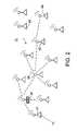
- FIG. 1is a block diagram of a wireless network.
- FIG. 2is a block diagram of a wireless network that includes a portion of the network of FIG. 1 .
- FIG. 3is a timing diagram showing a frequency hopping sequence and timing for a receiving device on a wireless network, such as that of FIGS. 1 and 2 .
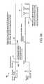
- FIG. 4is a flowchart showing a frequency hopping protocol.
- FIG. 5comprised of FIGS. 5A and 5B , shows timing diagrams depicting operation of the frequency hopping protocol, which includes a sending device's timing and a receiving device's timing used in the exchange of information between devices.
- FIG. 6shows timing diagrams depicting individual units of a preamble used in the frequency hopping protocol in relation to a normal operational mode of a receiving device.
- FIG. 7shows timing diagrams depicting how neighboring nodes respond, at different times, to a search packet transmitted by a sending node.
- FIG. 8shows timing diagrams depicting use of a preamble during the normal course of operation of two network nodes, particularly where a device's receiving duration is short.
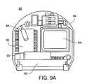
- FIGS. 9A to 9Cshow examples of devices on the wireless network of FIG. 1 or 2 that may implement the frequency hopping protocol.
- FIG. 1shows an exemplary wireless network 10 on which the process may be implemented.
- devices on, or entering, the networkmay communicate over one or more frequency channels.
- frequency hopping datais exchanged between devices upon entry of a device into the network.
- the frequency hopping datadescribes how each device communicates using frequency hopping, thereby enabling the devices to schedule communications for appropriate frequencies, times, and durations.
- Frequency hoppingincreases the capacity of the network because it allows network communications to overlap without substantially increasing collisions and packet loss.
- the Wireless NetworkThe Wireless Network
- Wireless network 10is a heterogeneous network, since devices on wireless network 10 need not perform the same functions.
- Wireless network 10includes endpoint devices 12 and 14 , intermediary devices 15 to 22 , and base stations 24 to 26 .
- Endpoint devices 12 and 14 and intermediary devices 15 to 22may communicate via radio frequency (RF) links.
- RF linksare shown as dotted lines.
- Base stations 24 to 26may communicate to the intermediary devices via RF links and are wired to a high-speed backbone 29 , through which base stations 24 to 26 communicate with a host computer 30 at a relatively high speed.
- High-speed backbone 29may be any type of wired or wireless medium, such as Ethernet or Wi-Fi (wireless fidelity).
- Each of endpoint devices 12 and 14 , intermediary devices 15 to 22 , and base stations 24 to 26defines a node of wireless network 10 .
- Each of these devicesincludes memory (not shown) that stores executable instructions and one or more processors (the one or more processors defining a processing system—not shown) for executing the instructions to perform functions described herein.
- the structure of endpoint devices 12 and 14may be the same as the structure of intermediary devices 15 to 22 , and the structure each base station 24 to 26 is the same. This may not be the case in other implementations.
- Each deviceis programmed with appropriate functionality.
- Each node of wireless network 10may enter a low-power, or “dormant”, mode when not communicating over wireless network 10 .
- a nodemay maintain some low-level operations; however, major processing functions are curtailed in order to conserve power.
- the node“wakes-up”, i.e., activates and enters its normal operational mode. During the normal operational mode, the node is again able to send/receive data over wireless network 10 .
- a network nodemay always enter the low-power mode whenever it is not communicating over wireless network or the network node may maintain its normal operational mode during some periods of non-communication over the wireless network.
- Reduced power consumption for network nodesis advantageous, since network nodes are often powered by low-capacity, small-size batteries, such as lithium coin cell batteries. Long life for batteries of this type can generally be achieved when average power consumption of a remote terminal (e.g., a node of the wireless network) is relatively low.
- the frequency hopping protocol described hereinallows network nodes to remain in their low-power modes for relatively long periods of time, thereby further decreasing the amount of power consumed by those nodes.
- the base stations, intermediary devices, and endpoint devices described abovemay be any type of computing device, such as a work station, a personal computer, a server, a portable computing device (e.g., a personal digital assistant or “PDA”), a cellular telephone, or any other type of intelligent device capable of executing instructions and connecting to a network.
- the base stations, intermediary devices, and endpoint devicescan execute any number of computer programs, including applications that are configured to generate, receive, and transmit data packets for use on the network.
- a device entering network 10may configure itself to operate as an intermediary device (e.g., a router or repeater) if necessary based on predefined criteria.
- an intermediary devicee.g., a router or repeater
- Such a devicemay also have the capabilities (and configuration) of an endpoint device described below.
- An endpoint devicemay be either a source or a destination of network data.
- one or more sensing devicesmay be connected to an endpoint device; other implementations may include endpoint devices without sensing devices.
- the sensing device(s)may be used to monitor physical systems, such as a processing plant, and variables, such as temperature.
- An endpoint devicemay acquire analog and/or digital signals from the sensing device(s) and transmit these signals to a base station via wireless network 10 .
- An antenna(not shown) may be included on each endpoint device to effect transmission. Antennas may also be included on the other wireless devices in the network.
- One or more actuatorsmay also be connected to an endpoint device in this implementation.
- the endpoint devicemay use analog or digital command signals to command the actuator(s). These command signals may originate in the endpoint device or in a host computer 30 . In the latter case, such command signals may be transmitted from host computer 30 , to a base station, and then to the endpoint device, either directly or through one or more intermediary devices in wireless network 10 .
- An intermediary deviceis an intermediate node of wireless network 10 that functions as a router or repeater to forward data sent by endpoint devices, other intermediary devices, and/or base stations.
- Intermediary devicestypically send the data in the format that the data is received and at the same rate as the data is received.
- Each endpoint device, described above,may configure itself to operate as an intermediary device, and vice versa.
- Intermediary devicesalso store routing information, such as a next hop along a network path to a data packet's intended destination, and a hop on a return path.
- a base stationis a node of the wireless network that may be connected to high-speed backbone 29 .
- Base stationsact as intermediaries between wireless network 10 and backbone 29 , performing any necessary data and protocol conversions to permit data exchange between the two.
- Base stations that do not connect to backbone 29may also be integrated into network 10 .
- Such base stations(not shown in FIG. 1 ) may interface to a host device, and may be connected to other host devices or to the backbone via a wireless link through, e.g., a Wi-Fi (wireless fidelity) connection.
- Wi-Fiwireless fidelity
- Host computer 30may also connect to high-speed backbone 29 .
- Host computer 30supervises wireless network 10 and performs tasks that include receiving, processing and storing data generated by endpoint devices, and issuing command signals to the endpoint devices.
- Host computer 30may also be used to reconfigure an endpoint device and/or intermediary devices to implement the wireless network described herein.
- wireless network 10The only requirement in forming wireless network 10 is that every endpoint device should be within the RF transmission range of a base station or an intermediary device, and every intermediary device should be within the RF transmission range of a base station or another intermediary device. Devices outside of their RF transmission range are typically not able to communicate directly with each other over wireless network 10 .
- the overall topology of wireless network 10resembles a spanning forest, in which the endpoint devices function as leaves, the intermediary devices function as branches, and the base stations function as roots. Like in a dense forest where trees can overlap, communication links among intermediary devices mesh to form a web-like structure, which enables the endpoint devices (leaves) and intermediary devices (branches) to communicate with multiple base stations (roots).
- Networksmay occupy the same physical space.
- Data packets for such networksare differentiated by a network group identifier (ID).
- IDnetwork group identifier
- Such networksmay even use the same devices, either in the same or in different roles.
- device 24may act as a router for one network and as a base station for another network; device 17 may operate as an endpoint device for one network and as a base station for another network, etc. Operation of devices in such different networks is as described herein.
- Devicesmay be programmed to operate as base stations, routers, or endpoint devices in one network by specifying the group ID of that network and the functionality of the device for that group ID.
- a host computermay initiate/control programming of the various devices or the devices may be programmed directly on the devices themselves.
- Network data packetstypically contain the network group ID for their corresponding network.
- networkssuch as network 10
- all of the base stationsmay be connected to host computer 30 .
- data packetsmay be stored and organized by host computer 30 .
- host computer 30maintains a central database comprised of packets from one or more endpoint devices.
- the base stationsare not all connected to the same host computer.
- different base stationsmay receive packets resulting from a single transmission of an endpoint device.
- Each base stationmaintains a separate database of packets that it receives.
- the various base stationsmay synchronize their databases periodically. Synchronization may occur via wireless connection or via a wired connection, such as Ethernet (if a wired connection exists among the various databases). This synchronization results in each base station containing a complete database of all packets that reach base stations in the network. Redundant databases such as these are particularly advantageous because they provide back-up in the event of failure of a base station on the network.
- the hello messageis a specialized data packet and is therefore referred to as a “search packet”.
- the search packetmay contain information, such as the identity of an endpoint device and a request to enter the wireless network.
- All intermediary devicese.g., routers or repeaters
- All intermediary deviceswithin the RF transmission range (typically 30 to 100 feet, but not limited to these values) of the endpoint device re-broadcast the search packet to seek connections with base stations or other intermediary devices within their respective RF transmission ranges.
- the intermediary devicesre-broadcast the search packet until the search packet reaches all of the base stations 24 to 26 . This technique of propagating the search packet through the network is referred to as “flooding” the network.
- the base stationWhen a base station receives a search packet, the base station responds by generating and broadcasting a confirmation packet.
- the confirmation packetis also propagated throughout the entire wireless network 10 by flooding the network. Eventually, the confirmation packet reaches the endpoint device that initiated the hello message. At this point, communication among the network nodes is possible.
- intermediary deviceskeep track of which node sent them the confirmation packet, i.e., an immediately preceding network node along the route.
- Each intermediary devicestores a pointer in memory that points to this node.
- the pointersenable the intermediary devices to identify neighboring nodes that can be used in transporting a data packet closer to a base station. These neighboring nodes are referred to as master nodes, or simply “masters”.
- master nodesacts as a primary recipient of data from its dependent, or “slave”, node.
- terminal-initiated pollingis that an endpoint device need not wait to join a wireless network. That is, since the endpoint device initiates entry into the wireless network, the endpoint device controls when to establish a presence in the wireless network. The endpoint device is not required to wait for a periodic beacon signal from a base station before joining the wireless network.
- a heterogeneous networkis formed without a rigidly prescribed hierarchy.
- every node in wireless network 10can assume the role of an endpoint device or an intermediary device and can change dynamically based on criteria specified by a user.
- the wireless networktakes advantage of the flexibility of homogeneous networks and the power efficiency of heterogeneous networks.
- a process for joining wireless network 10is described with respect to FIG. 2 .
- FIG. 2shows a wireless network 31 , which may be part of wireless network 10 .
- a target devicesuch as device 40 in FIG. 2
- device 40attempts to locate a packet forwarding device, such as an intermediary device or base station, in its neighborhood.
- a packet forwarding devicesuch as an intermediary device or base station
- Device 40does this by broadcasting a search packet to the network, as described in the preceding and following sections.
- the network neighborhoodincludes all devices to which device 40 has a direct RF link; although this application is not limited to this definition of “neighborhood”.
- Device 40receives response(s) to its search packet from its neighbor(s). Device 40 uses those responses to determine, e.g., if one or more intermediary devices is within its network neighborhood (meaning that device 40 can establish an RF link to such a device). If so, device 40 selects an intermediary device that satisfies predefined criteria, and designates that device as its primary master (and others as secondary, tertiary, etc. masters, if applicable). Device 40 then joins the network as an endpoint device with a low duty cycle. The same process occurs if device 40 identifies a base station in its neighborhood.
- Criteria for selecting the primary mastermay include, but are not limited to, the distance to a base station (or gateway), the quality of the communication link to the intermediary device, and the battery capacity of the intermediary device.
- device 40may select a primary master node having less than a certain number of hops to a base station or endpoint device.
- device 40may select the primary master based also (or solely) on other criteria. For example, device 40 may select a node having a link with low amounts of noise, and/or having a large battery capacity (thereby ensuring more reliable operation of the primary master).
- device 40will start operating as an intermediary device (e.g., a router).
- an intermediary devicee.g., a router
- Code programmed into device 40initiates its operation as a router, which includes forwarding data packets, maintaining routing information, and may enter a low-power mode less often, among other things.
- device 40“listens to” transmissions from neighboring devices, such as node 43 .
- Node 43in this case, is an endpoint device, since it is not an intermediary device or a base station (if it were an intermediary device or base station, device 40 would have recognized it as such in response to device 40 's initial attempt at entry into the network).
- Device 40“listens for” data transmissions from node 43 , not search packet transmissions. This is because transmission of a search packet implies that node 43 is looking for connection to network 10 . A data transmission, on the other hand, implies that node 43 is already connected to network 10 .
- device 40After device 40 detects a data transmission from node 43 , device 40 attempts to determine if node 43 is connected to network 10 . To do this, device 40 may listen for re-transmission of the same data packet. Re-transmission of the same data packet implies that node 43 is not connected to the network. Device 40 may listen for an acknowledgement (or “ack”) packet in response to the original transmission. The ack packet is sent by another node (e.g., node 42 ) that is on the network. This may not always work, however, because device 40 may be unable to receive the ack packet due, e.g., to a distance from a node transmitting the ack packet. Device 40 may send a packet to node 43 to determine its connectivity. This packet may advise node 43 of the existence of device 40 , and ask node 43 whether node 43 is connected to the network.
- ackacknowledgement
- device 40may send a data packet to node 43 asking node 43 (which, as noted above, is an endpoint device) to reconfigure itself as a router for device 40 .
- Node 43decides whether to configure itself as a router based, e.g., on its capabilities, available bandwidth, network access, and the like.
- device 40then reconfigures itself to be an endpoint device that routes communications through node 43 .
- Device 40selects node 43 to be its own primary master node. If node 43 is not connected to the network, and no other nodes are available to act as a router for device 40 , after a period of time device 40 may configure itself as an endpoint device.
- Device 40may be programmed to reconfigure itself as an endpoint device after operating as a router for a predetermined amount of time, e.g., one hour, or more or less than one hour. Any time period may be used. As noted above, device 40 may enter the low-power mode periodically. Upon exiting (“awakening”) from the low-power mode, device 40 may again try to establish a connection to the network as an endpoint device, as described above. If that is not successful, device 40 may try to establish a connection to the network as a router in the manner described above, i.e., by configuring itself as a router, listening for non-search packet transmissions, etc.
- a predetermined amount of timee.g., one hour, or more or less than one hour. Any time period may be used.
- device 40may enter the low-power mode periodically. Upon exiting (“awakening”) from the low-power mode, device 40 may again try to establish a connection to the network as an endpoint device, as described above. If that is not successful,
- the amount of time that device 40 remains configured as a routermay be programmed into device 40 .
- this amount of timemay be dictated by network traffic (e.g., search packets) in the vicinity of device 40 .
- network traffice.g., search packets
- a large number of search packets detected in the vicinity of device 40indicates that there are devices in the neighborhood (which, perhaps, are just not yet connected to the network).
- few search packets detected in the vicinity of device 40indicates that there may be few devices in the neighborhood (and, perhaps, device 40 is isolated).
- device 40configures itself as a router for a longer period of time (since more devices implies a higher probability of achieving a network connection).
- device 40configures itself as an endpoint device that can enter low-power mode for a relatively long period of time. In this case, device 40 “awakens” from the low-power mode less frequently, since there is less of a chance of achieving a network connection.
- Device 40may operate as an intermediary node for one or more other devices on network 31 . Assuming that device 40 has a link to a master intermediary device, device 40 may decide whether to remain an intermediary device for neighboring endpoint devices. From the intermediary device IDs (identifiers) reported by neighboring endpoint devices, device 40 can identify whether any one of the neighboring endpoint devices relies on device 40 as its only intermediary device. For example, device 40 can query other intermediary devices for routing information. If at least one device does rely solely on device 40 , then device 40 remains an intermediary device; otherwise device 40 configures itself as an endpoint device.
- intermediary device IDsidentifiers
- device 40may configure itself as endpoint device.
- the predefined timecan be programmed into the device or selected based on one or more parameters.
- One example of such a parameteris the frequency with which a dependent endpoint device communicates with the intermediary device; i.e., the less frequent the communication from the endpoint device, the more often device 40 configures itself as an endpoint device.
- an intermediary deviceWhen an intermediary device becomes a master intermediary device of a high number of nodes, a substantial amount of traffic can flow into the intermediary device. This can result in data congestion and, possibly, frequent data packet collision. Excessive traffic can be diverted for an overloaded intermediary device by obtaining a new intermediary device from endpoint devices in the neighborhood. In this situation, an intermediary device can issue and broadcast a router election request to its neighboring endpoint devices. Upon receiving this router election request, an endpoint device responds with a message indicating its operating status, which may include the ID of intermediary devices that it communicates with, its data generation rate, its remaining battery charge, etc.
- the intermediary deviceAfter receiving responses from all neighboring endpoint devices, the intermediary device selects a new intermediary device based on a certain criteria. For example, an endpoint device that communicates with the most number of intermediary devices can offer higher connectivity with the rest of the network; an endpoint device with a relatively low data generation rate can offer more bandwidth to route data for other nodes; and an endpoint device with the most battery charge can afford to operate with a high duty cycle.
- the intermediary deviceinstructs the selected node to configure itself as a router.
- One purpose of instructing one of the neighboring endpoint devices to be a routeris to divert traffic. Once a new router is elected, the intermediary device need not select this new router as its own primary master.
- the overloaded intermediary deviceelects a new router simply to increase the number of intermediary devices in the neighborhood, so that traffic congestion through the overloaded intermediary device can be alleviated.
- Every node in the networkmay continually search for a better primary master intermediary device in the manner described above.
- a nodecan have one or multiple alternative masters in addition to its primary master. As such a new primary master can be selected from the alternative masters.
- a nodecan broadcast a router election request to its neighboring nodes. Upon receiving the router election request, a neighboring node, either an endpoint device, an intermediary device or a base station, will respond with its operating status. After reviewing all responses, the requesting node selects a new primary master from the neighboring nodes.
- the selected nodeis already an intermediary device, it is simply recognized as the new primary master of the requesting node. If the node is an endpoint device, the requesting node issues a message to request the endpoint device to become an intermediary device as well as the primary master of the requesting node. The endpoint device decides whether to become an intermediary device based, e.g., on its capabilities and connection to the network. If it does become an intermediary device, the endpoint device notifies the requesting node.
- Every nodemay seek to operate as an endpoint device.
- a nodewill serve as an intermediary device when the node recognizes that either there is no intermediary device available in its neighborhood, or all neighboring intermediary devices cannot provide reliable connectivity due, e.g., to excessive traffic or radio link issues.
- the process for joining the wireless networkmay lead to electing a relatively small number of intermediary device nodes based on predefined criteria needed to maintain network connectivity.
- the criteriacan include, but are not limited to, one or more of the factors mentioned above, such as a number of hops to a base station, a reliability of the communication link, and remaining battery life.
- the probability of an endpoint device becoming an intermediary device nodecan be adjusted by tuning these factors. These factors may be tuned, e.g., via host computer 30 and/or by directly accessing the appropriate network device and programming the appropriate values.
- the frequency hopping protocol described belowis described in the context of a heterogeneous wireless network, such as wireless network 10 .
- the frequency hopping protocolis not limited to use with a heterogeneous network, but rather may also be used with a homogeneous network, e.g., a network in which all devices have the same structure and/or function.
- a wireless network that includes only routersmay benefit from the frequency hopping protocol because the frequency hopping protocol allows the routers to operate with a reduced duty cycle (as described below). As a result, batteries that power the routers will use power less quickly.
- the frequency hopping protocoldoes not require a common time base throughout an entire wireless network. That is, nodes of a wireless network communicate with their neighboring nodes based on knowledge of the neighboring nodes' wake-up times, wake-up durations, and/or channel sequences (as described below).
- One advantage of this processis that it allows nodes to wake-up more frequently, each time doing so with a relatively short duration. Because nodes wake-up more frequently, packets can propagate through the network relatively quickly. As a result, the wireless network can operate with increased robustness (proactive channel switching), relatively high bandwidth, relatively low power consumption, and relatively low latency.
- one or more nodesmay communicate using frequency hopping.
- frequency hoppingmay be implemented by providing windows, during which network nodes can receive communications from other nodes.
- a receiving nodeis a node that is to receive communication.
- the receiving nodewakes, meaning that it activates and operates in its normal operational mode, at times 45 , 46 , etc. for predefined durations.
- the durationsare labeled as MN_RX_time, where “MN” stands for “Mesh Node” and “RX” for “receive”(“TX” stands for “transmit”).
- MN_RX_timemay also be changed on the fly depending on the network status, and each node may have a different MN_RX_time.
- the receiving nodewakes in predefined frequency channels, which are labeled Ch 7 , Ch 11 , etc. At other times 47 , 49 , etc., the receiving node may be in a low-power, or dormant, mode, which is labeled MN_sleep_time.
- node 15( FIG. 1 ) as an initial example.
- the receiving nodehere node 15
- the receiving nodeis able to receive communications only in specified frequency channels. For example, at time 46 , node 15 wakes-up in channel (Ch) 11 for a duration of 200 ⁇ s (microseconds). If another node on the wireless network wants to send a communication to node 15 , the other node must do so within the 200 ⁇ s duration in Ch 11 ; otherwise, it must wait until node 15 wakes-up again (e.g., in another 10 ms (milliseconds)). When node 15 wakes again, however, it may wake in a different frequency channel (Ch 2 ), although it will typically (although need not) wake for the same duration.
- Chchannel
- a node that wants to communicate with node 15must therefore know the times at which node 15 wakes, the durations for which node 15 is awake, and the channel sequence for node 15 (so that the node wanting to communicate with node 15 can determine the channel in which to send communications to node 15 ).
- nodesneed not have the same wake-up times, wake-up durations, or channel sequences.
- node 15may wake up once every 10 ms for 200 ⁇ s
- node 16may wake up once every two seconds for 200 ⁇ s
- node 17may wake up once every half second for 50 ⁇ s, and so on.
- node 15may follow a random channel sequence of 7, 11, 2, 10 . . . 12, node 16 may follow a channel sequence of 16, 15, 14, 13 . . . 1, and node 17 may follow a channel sequence of 1, 2, 3, 4 . . . 16.
- the channel sequencesmay be stored in frequency hopping lists in memory on each node.
- each nodemay follow a different channel sequence, each node typically (although need not) maintains its same sequence. That is, node 15 repeats its sequence of 7, 11, 2, 10 . . . 12 periodically, node 16 repeats its sequence 16, 15, 14, 13 . . . 1 periodically, and node 17 repeats its sequence of 1, 2, 3, 4 . . . 16 periodically.
- each nodecommunicates over sixteen channels; however, in other implementations, some nodes may communicate over less than, or more than, the sixteen channels specified herein. For example, in 900 MHz RF operation, there may be 50 frequency channels.
- a sending nodei.e., a node that is to send communication
- a sending nodecan typically wake and send communications in any channel irrespective of its own receiving frequency channel sequence and timing.
- a receiving nodetypically sends an ack packet back to a sending node to acknowledge receipt of a communication. If the sending node does not receive an appropriate ack packet in response to a communication, the sending node may re-send the communication at a subsequent time and frequency channel for the receiving node (which may, or may not, be the time and frequency that immediately follows the current time and frequency). For example, the sending node may be programmed to retry the communication at a random subsequent time, thereby reducing the chances of collisions with other sending nodes. This process may be repeated until the sending node receives an ack packet from the receiving node.
- each nodestores, and keeps track of, clocks of its neighboring nodes that are both upstream and downstream in a communication path.
- Search response packetsinclude time stamps and may include the channel sequence of the node that sends the ack packet.
- the receiving devicewill adjust the neighbor's clock in its neighborhood database to the received time.
- a nodeshould store at least 32 independent clocks (or other next-time-to-wake-up information) in its neighborhood database.
- Each clockmay include at least two bytes, which can store 65536 clock ticks. So, with increments of 1 ms (a clock tick), a clock can cover up to 65 seconds of next time-to-wake-up information. This may be done for all communications, not just search response packets.
- the frequency hopping protocol(which is referred to herein as “the frequency hopping protocol”) is provided that enables a device to discover how neighboring network nodes perform frequency hopping, e.g., to discover their frequency sequence data, wake-up data, and duty cycle data.
- the frequency sequence data(or simply sequence data) is usable to obtain a sequence of frequencies at which a neighboring node activates; the wake-up data corresponds to times at which the neighboring node activates; and the duty cycle data corresponds to durations of time for which the neighboring node activates.
- the hello message(e.g., the search packets) is transmitted between a preamble (described below) used in the frequency hopping protocol and listening frequency(ies) that follow the preamble.
- the frequency hopping protocolis also used to broadcast over the wireless network, as described below.
- a sending deviceentering a wireless network outputs ( 50 ) a preamble 51 .
- the preambleis a sequence of packets that are output from the device.
- the data packetsmay be IEEE802.15.4 data packets, and each packet may be, e.g., 1 ms ( ⁇ 25 bytes).
- the preambleis designed, essentially, to get the attention of nodes that neighbor the device.
- the preamblemay represent a specific data pattern, e.g., “01010101 . . . ”.
- the preambleidentifies a start of communication between device 40 and one or more of its neighbors.
- a node that neighbors the deviceis any node that is part of the wireless network and that is within a wireless transmission range of the device.
- the preambleis transmitted in one frequency channel (e.g., Ch 8 in FIG. 5 ), and is structured so that it exceeds a maximum activation time of all nodes on the wireless network by a factor N, where N is equal to at least a maximum number of frequencies on the wireless network. This ensures that all neighboring nodes of device 40 will wake in the frequency channel of the preamble and thereby receive the preamble at least once during its activation cycle.
- the preamblewill be at least 80 s (16 ⁇ 5 s).
- the time between activationalso known as the node's sleep cycle
- the preamblemay be about 3.2 s. It is noted that, in some circumstances (described below), a preamble of greater than 400 ms may need to be divided among multiple frequency channels in accordance with Federal Communications Commission (FCC) regulations.
- FCCFederal Communications Commission
- the duration 52 (MN_RX_time) during which the receiver listens for communications in a frequency channelshould be at least twice as long as the length of a preamble packet unit 54 . This is done in order to ensure that at least one complete preamble packet (or “preamble unit”) is recognized by the receiver. If a start of frame delimiter (SFD) is used to detect the preamble, MN_RX_time need be only slightly longer than a preamble unit.
- SFDstart of frame delimiter
- the duration of the preamblemay be expressed mathematically as follows.
- Each preamble unitcontains a time-to-tail end value (so that any neighboring node that receives the preamble packet unit knows when to return to the preamble channel to receive a search packet).
- L_puthe length of the preamble packet unit in milliseconds.
- MN — RX _time2 *L — pu.
- MN_cycle_timeis the duty cycle of a network node, and is equal to M_ps*2*L_pu, where M_ps is a predefined power saving multiplier.
- the power saving multiplier M_psis essentially the ratio of MN_cycle_time to MN_RX_time. A higher M_ps means a higher ratio of sleep time to activation time, resulting in more power savings.
- CSMACarrier Sense Multiple Access
- listeningis conducted before the preamble is output in order to make sure there is currently no other preamble in the same frequency channel. If there is already a preamble in that frequency channel, the node can decide to wait until an on-going search process is over or to jump to another frequency channel that has no on-going search process, and begin its search process immediately in that other frequency channel, i.e., send out the preamble in that other frequency, etc.
- the preamblemay include timing information. More specifically, following the preamble, the neighboring nodes transmit their sequence data, wake-up data, and duty cycle data to device 40 . The neighboring nodes therefore need to know when the preamble will end so that they can begin transmission.
- the preambletherefore may include timing data, which identifies the end of the preamble.
- the preambleis a sequence of data packets transmitted in a stream. Each data packet may contain a countdown time, which indicates the remaining length of the preamble. In other implementations, only select data packets may contain the countdown time.
- device 40transmits ( 56 ) its search (or hello) packet 57 at 58 a .
- the search packetincludes the sequence data, wake-up data, and duty cycle data for device 40 . That is, the search packet include the sequence of frequencies in which device 40 listens for communications, the times at which device 40 listens in those frequencies, and the listening duration. This information is stored in frequency hopping list(s) in neighboring nodes, and enables those nodes to send communications to device 40 .
- device 40listens ( 59 ) in one or more frequencies at 58 b for communications from its neighboring nodes, specifically, the sequence data, wake-up data, and duty cycle data for the neighboring nodes (e.g., nodes 42 and 43 , assuming, for this example, that node 43 is already a member of the network and within the transmission range of node 40 ). That is, the sender goes into receive mode and waits to receive search responses (if sending a broadcast packet, the sender will resume its sleep/wake cycle).
- frequency hopping datasuch as sequence data, wake-up data, and duty cycle data
- device 40may listen in a single frequency or in multiple frequencies. In other words, device 40 may frequency hop during the listening phase 59 following the preamble. In any case, the frequency(ies) that device 40 will be listening in should be known to the neighboring nodes.
- device 40listens in the same frequency channel in which the preamble was sent.
- a neighboring nodeidentifies device 40 's listening frequency(ies) by the frequency of the preamble (i.e., it knows beforehand that the two are the same).
- a neighboring nodee.g., node 42
- locks onto that channelin FIG. 5 , channel (Ch) 8 at 63
- the node's internal channel hopping clockcontinues to run so that the node can resume its frequency hopping sequence 60 at 58 c (after sending its frequency hopping data to device 40 ) as if that sequence were never interrupted.
- the neighboring nodesuse timing data in the preamble to schedule a communication to device 40 . That is, a neighboring node keeps track of the amount of time left in the preamble and, following the preamble, sends its frequency hopping data to device 40 in the same frequency channel as the preamble. Prior to sending its frequency hopping data (e.g., time 61 ), the node hops frequencies, and performs transmitting and receiving operations, in accordance with its usual schedule.
- frequency hopping datae.g., time 61
- device 40sends the same preamble packet without timing data and, when it is near the end of preamble period, device 40 sets a flags in the preamble packet indicating the upcoming end of the preamble (sometimes referred to as its “tail”).
- the neighboring nodesmay check between wake-up times in order to determine whether the preamble is near its end. Prior to this, the node hops frequencies, and performs transmitting and receiving operations, in accordance with its usual schedule.
- the preamblemay contain data, such as timing data, indicating that that the preamble is near its end.
- a nodedetermines that the preamble is near its end (e.g., within a predefined time of its end)
- the nodelocks onto the channel that the preamble is transmitted in, and wakes only in that channel. It is noted, however, that the node's internal channel hopping clock continues to run so that the node can resume its frequency hopping sequence (after sending its frequency hopping data to device 40 ) as if that sequence were never interrupted.
- device 40In a case where device 40 listens in multiple frequencies, device 40 provides the neighboring nodes with the sequence data, wake-up data, and duty cycle data for the listening period.
- This informationcan be provided in a search packet which is broadcast following the preamble, and in the same channel as the preamble (thereby ensuring that the neighboring nodes will receive the search packet), but before the listening period. Alternatively, this information may be provided in the preamble itself.
- the neighboring nodestransmit their frequency hopping data, such as their sequence data, wake-up data, and duty cycle data to device 40 .
- Device 40receives ( 62 ) the frequency hopping data for each node, and stores it in memory in association with a node identifier and the clock for the node.
- device 40knows the frequency hopping data for its neighboring nodes, and vice versa.
- Device 40is thus able to keep track of the current frequency channel, wake-up time, and duty cycle of all of its neighboring nodes, and the neighboring nodes can do the same for device 40 .
- a number of neighboring nodesmay attempt to transmit frequency hopping data to device 40 .
- first, second, third, etc. neighborsmay all attempt to transmit their sequence data, wake-up data, and duty cycle data to device 40 . If all devices attempt to transmit at the same time, this can result in data collision, and the required data may not reach device 40 . Therefore, the listening mode of device 40 is structured to be long enough so that numerous nodes can send their data at different times. For example, the listening mode may be 100 ms, 500 ms, or longer.
- the nodes of network 10are each programmed to send their frequency hopping data at a random time during the listening mode of device 40 .
- each neighboring nodemay contain an algorithm that picks a random time during the listening mode to send its frequency hopping data. Sending data at random times reduces the possibility of a collision between frequency hopping data from different nodes. In the event of a collision, a node will not receive an ack packet back from device 40 . In this case, the node re-sends its frequency hopping data at a different time. If device 40 is frequency hopping during the listening mode, its neighboring nodes must also take this into account when sending their frequency hopping data. This contingency is shown in FIG. 7 , where node 42 sends its frequency hopping data at a first time 64 in channel 6 and node 43 sends its frequency hopping data at a second time 65 in channel 1 .
- device 40may each store an algorithm, which receives a single “seed” number and which processes that seed number to generate a frequency hopping sequence. For example, device 40 may receive a seed number from neighboring node 42 and process that seed number to determine the sequence of frequencies through which node 42 hops to receive data. As a result, only a single number is transmitted instead of a whole sequence, thereby reducing network traffic.
- the frequency hopping channelshould be selected from a specified set of channels as randomly as possible with a uniform distribution so that, on average, the device will spend about the same amount of time on each channel.
- a calculationmay be performed iteratively to produce a new random number from each iteration.
- a seed numberwill generate the first random number, which corresponds to the first frequency channel.
- This first random numberis fed into the calculation as the new seed number, which then generates a second random number, which corresponds to the second frequency channel.
- This processcan continue indefinitely to select new channel during frequency hopping.
- the calculationis used to generate a random number that is 32-bits long in a binary representation.
- a single number between 1 and 16is generated, and only the last 4-bits of this 32-bit random number are used.
- the 32-bit long numbercan be divided by 16 and the remainder used—a modulus operation.
- the 32-bit long random numberis used as the new seed number I, every iteration so that it is less likely that the random sequence becomes periodical.
- random_seedrandom_seed * 1103515245 +12345; return (unsigned int)(random_seed / 65536) % 32768; ⁇
- This functionwill return a random number between 0 to 32767, depending on the seed number. If the total number of channels is 16, it is possible to use the least significant four bits to generate a random number between 0 and 15. As described above, the first random number obtained from the seed number can replace the seed number in the foregoing process, which is then used to generate a next random number. Via this method, it is possible generate a full frequency hopping sequence of 16 channels using one seed number.
- nodespowers-up exactly at the same time. For example, if the nodes are line-powered, and line power is restored after a power outage, all nodes connected to the same line power will turn on at the same time. In this case, there is a chance that the wake-up times and frequency channels may be exactly the same for all nodes. Although this scenario may be acceptable for certain applications, this is typically undesirable because it counteracts the asynchronous behavior of the proposed frequency hopping protocol to increase the overall communication capacity of the network. So, whenever a node powers up, the node may have a certain amount of random “dead time” before the node starts running. This way, it is unlikely that many nodes will share the same wake-up schedule and frequency channel.
- node Cmay not have enough time to prepare for the data transmission to node B. Furthermore, if two listening slots are too close together, it may not be practical for node C to enter its dormant mode and then wake up again in the short time between slots. In this case, it may be better for the node C to remain awake after sending the data packet to node A, and to wait for the listening slot of node B while awake.
- One way to reduce conflict caused by close proximity of listening slots of multiple neighboring nodesis to adjust the initial wake-up schedules of those nodes following their activation (power-up). For example, when a node powers-up, it will send a search packet and collect information about its neighboring nodes, such as wake-up times, wake-up durations, and channel sequences. Accordingly, a node that is entering the network may select its own wake-up time after collecting information from neighboring nodes, and choose a wake-up time that reduces (e.g., minimizes) conflicts with neighboring nodes.
- a devicecan consume a relatively large amount of power due to the length of its preamble. As a result, it is advantageous to reduce the amount of times a device must initiate communication using the preamble.
- One way of doing thisis to “piggy-back” node frequency hopping (and other) data.
- node 42stores the frequency hopping data for its neighbors, including those that are out of the transmission range of device 40 , such as node 28 . Accordingly, when transferring its frequency hopping data during the listening mode of device 40 , node 42 may also transfer, to device 40 , the frequency hopping data of node 28 , along with the identity of node 28 (which device 40 then stores in memory). Thus, device 40 will also receive the frequency hopping data of node 28 .
- node 28stores the frequency hopping data for its neighbors, including those that are out of the transmission range of node 42 , such as node 26 .
- Node 28may transmit this frequency hopping data to node 42 , along with its own frequency hopping data.
- Node 42may then transfer, to device 40 , the frequency hopping data of two other nodes, one of which (node 26 ) is outside the transmission range of node 42 .
- preamblesmay be extended to normal node communication in order to increase the duty cycle of network node (e.g., by increasing the waking durations of the nodes).
- the receiving nodee.g., node 15
- the sending nodee.g., node 12
- a relatively short time shift in the internal clock of the sending nodemay effectively prevent the sending node from communicating with the receiving node (if the receiving node's waking duration is sufficiently short).
- the sending nodemay output a relatively short preamble (e.g., 5 ms or 10 ms) in the appropriate channel prior to the expected waking duration of the receiving node.
- the sending nodeoutputs a preamble 70 in channel 6 following the receiver's waking time in channel 10 .
- the receiving nodedetects the preamble during its receiving duration in channel 6 and extends its receiving duration 71 , as shown.
- sending node 12sends a data packet 72 to the receiving node in channel (Ch) 6 .
- the receiving nodedetects an “end-of-frame” indication in the data packet, the receiving node ends the extended receiving duration 71 at 68 a .
- the sending nodegoes into receiving mode 74 to receive an ack packet 75 from the receiving device. It is noted, however, that the internal channel hopping clocks of both devices continue to run so that the devices can resume their frequency hopping sequence 76 (after the extended receiving duration) as if that sequence were never interrupted.
- An alternative to the timing shown in FIG. 8is to make a whole data packet fit into a single MN_sleep_time of the receiving device.
- the preambleis thus long enough to cover an MN_RX_time. Accordingly, the frequency hopping sequence need not be disturbed.
- the FCClimits communication in a single channel to 400 ms with a narrow-band radio.
- DSSSDirect Sequence Spread Spectrum
- 2.4 GHz operationthere are many standard-based radios (e.g. IEEE IEEE802.15.4) available with DSSS capabilities. Therefore, if a preamble is to be longer than 400 ms during 900 MHz operation, then the preamble may be transmitted in multiple frequencies. This is referred to herein as “channel grouping”.
- a preamble that is longer than 400 msmay be divided into multiple sections and transmitted in different frequency channels in the 900 MHz spectrum. For example, a 1.5 s preamble may be split into four (or more) segments, which may be of equal or non-equal length.
- a node transmitting the preamblechanges the frequency channel and continues transmission of the preamble in a new frequency channel. This is done until the entire 1.5 s preamble is transmitted, without violating FCC regulations.
- channel groupingFor the reasons explained above, at least one listening slot of each neighboring node should be covered by the preamble, even though the preamble is being transmitted multiple channels. To achieve this, a process called “channel grouping” may be used.
- a preamblemay be transmitted in N different channels so that each channel includes no more than 400 ms of preamble.
- group 1may include channel 1 to channel 10 and group 2 may include channel 11 to channel 20 .
- the sequenceshould be defined so that channels 1 through 10 are selected first, followed by channels 11 to 20 .
- the preamblehops only inside one group. For example, if the node transmitting the preamble selects group 2 , the preamble should hop only inside group 2 . (e.g., among channel 11 to 20 ). Since the preamble include N segments, each group should include at least N channels. This means that total number of available RF channels should be larger than N ⁇ N. This is because a preamble with N segments needs N groups of channels, and each group needs to include minimum of N channels.
- thismay only apply when each channel is a narrow-band (e.g., 900 MHz) channel.
- channel groupingis not necessary, but may also be used.
- CC2420transceiver from Chipcon Products.
- CC2420is a low-cost transceiver designed specifically for low-power, low-voltage RF applications in the 2.4 GHz unlicensed ISM band.”
- a whole packet(not just a byte) constitutes a unit of the preamble.
- each preamble unitis approximately 1 ms.
- MN_RX_timeis at least 2 ⁇ the preamble unit size, or 2 ms. To achieve 100 ⁇ power savings, MN_sleep_time should be about 200 ms.
- the CC2420provides sixteen channels.
- the minimum preamble length that can cover all sixteen channelsis 3.2 s (200 ms*16 channels). Since the CC2420 operates in the 2.4 GHz range with DSSS capability, there is no limit on the maximum time the CC2420 can stay in one channel. So, the preamble can stay in the same channel for any length of time. Alternatively, the preamble may be split among two to four channels. That is, the preamble may be transmitted in different frequency channels.
- the start of a data packetcan be fit into the MN_RX_time ( ⁇ 2 ms) window of a receiving device.
- the SFDwill be detected by the receiving device before MN_RX_time expires, and the MN_RX_time will be elongated until packet reception is complete.
- several short preamble packetse.g., IEEE802.15.4 packets may precede the real data packet.
- This stream of short preamble packetsmay include five to ten short IEEE802.15.4 packets ( ⁇ 1 ms/packet). The result will be a preamble of about 10 ms, which will enable the 2 ms MN_RX_time window to capture at least one preamble packet even if there is ⁇ 5 ms clock drift.
- the receiverOnce the receiver identifies the preamble packet(s) in the MN_RX_time window, the receiver will continue listening in the same frequency channel (as described above) in order to receive the real (i.e., non-preamble) data packet.
- ack packetsare sent on a next hop channel after regular packet transmission. Alternately, ack packets may be sent on the same channel as regular data packet transmission.
- Clock driftmay be an issue when the interval between packet exchanges becomes quite long.
- each node of a wireless networksends a local “heartbeat packet” to each of its parent nodes (primary, and secondary, and so on) in a given interval. For example, if the clocks of neighboring nodes must be adjusted every 40 seconds to keep the drift in the acceptable range, the local heartbeat may be generated, and sent to each parent node, at least every 40 seconds. If a data packet is sent out to a parent node, the data packet may act as a replacement for the local heartbeat packet
- the frequency hopping protocolmay be used when a device enters into a network and when a device broadcasts over the network. That is, during broadcast, a device needs to get the attention of all of its neighbors. Since the neighbors may be in different frequencies, sending a preamble and proceeding in the manner described above enables a device to broadcast information to its neighbors, who then may propagate that information to their neighbors using the frequency hopping protocol, and so on until every node on the network has received the information.
- FIGS. 9A to 9Cshow block diagrams of one example of a network device 80 that may implement the processes described herein.
- Network device 80is a self-contained, miniaturized computer. As shown in FIGS. 9A and 9B , network device 80 includes first processing unit 82 , RF transceiver 84 , second processing unit 86 , low clock frequency crystal 88 , high clock frequency crystal 90 , and I/O connector 92 , all mounted on circuit board 94 . As shown in FIG. 9C , a power source 96 , such as a battery, may be attached to the back of circuit board 94 . A memory containing instructions to be executed by each processing unit may be included inside each processing unit or one or more such memories (not shown) may be mounted on circuit board 94 .
- first processing unit 82operates at a clock frequency of 32 kHz
- second processing unit 86operates at a clock frequency of 4 MHz.
- a coordinating protocoloperates so that network device 80 may perform signal processing and RF transmission with increased power efficiency.
- the coordinating protocolis used to control the operation of network device 80 by assigning tasks and operations to the processing units based upon the speed required to perform a given task of function.
- the coordinating protocolis designed to assign tasks to the various processing units with the result being increased power efficiency on network device 12 .
- the coordinating protocolwill allow CPU 82 to assign a given task or operation (such as joining or establishing a presence in wireless network 10 ) to itself or to CPU 86 based upon the speed requirements of the task or operation and the clock frequencies of the processing units. Tasks and operations which require lower clock frequencies will be assigned to CPU 86 with the lower clock frequency. Because CPU 86 operates at lower clock frequency, the power efficiency of the system as a whole is increased. When the task load of the system is low enough, the CPUs may be shut-off or placed into low-power mode to further increase the power efficiency of the system.
- the processes described hereinincluding, but not limited to, the frequency hopping protocol (hereinafter referred to collectively as “the processes”) may find applicability in any computing or processing environment.
- the processesmay be implemented using hardware, software, or a combination thereof.
- the processesare not limited to use with the hardware and software described herein; they may find applicability in any computing, processing or networking environment and with any type of machine that is capable of executing machine-readable instructions.
- the processesmay be implemented using digital electronic circuitry, or in computer hardware, firmware, software, or in combinations thereof.
- the processescan be implemented via a computer program product, i.e., a computer program tangibly embodied in an information carrier, e.g., in one or more machine-readable storage devices/media or in a propagated signal, for execution by, or to control the operation of, one or more data processing apparatus, e.g., a programmable processor, a computer, or multiple computers.
- a computer programcan be written in any form of programming language, including compiled or interpreted languages, and it can be deployed in any form, including as a stand-alone program or as a module, component, subroutine, or other unit suitable for use in a computing environment.
- a computer programcan be deployed to be executed on one computer or on multiple computers at one site or distributed across multiple sites and interconnected by a communication network.
- Actions performed by the processescan be performed by one or more programmable processors executing one or more computer programs to perform the functions of the processes.
- the actionscan also be performed by, and the processes can be implemented via, special purpose logic circuitry, e.g., one or more FPGAs (field programmable gate array) or ASICs (application-specific integrated circuit).
- FPGAsfield programmable gate array
- ASICsapplication-specific integrated circuit
- processors suitable for execution of a computer programinclude, e.g., both general and special purpose microprocessors, and any one or more processors of any kind of digital computer.
- a processorwill receive instructions and data from a read-only memory or a random access memory or both.
- Elements of a computerinclude a processor for executing instructions and one or more memory devices for storing instructions and data.
- a computerwill also include, or be operatively coupled to receive data from, or transfer data to, or both, one or more mass storage devices for storing data, e.g., magnetic, magneto-optical disks, or optical disks.
- Information carriers suitable for embodying computer program instructions and datainclude all forms of non-volatile memory, including by way of example, semiconductor memory devices, e.g., EPROM, EEPROM, and flash memory devices; magnetic disks, e.g., internal hard disks or removable disks; magneto-optical disks; and CD-ROM and DVD-ROM disks.
- semiconductor memory devicese.g., EPROM, EEPROM, and flash memory devices
- magnetic diskse.g., internal hard disks or removable disks
- magneto-optical diskse.g., CD-ROM and DVD-ROM disks.
- the processor and the memorycan be supplemented by, or incorporated in, special purpose logic circuitry.
- the processescan be implemented via a computing system that includes one or more back-end components, e.g., a data server, or that includes one or more middleware components, e.g., an application server, or that includes one or more front-end components, e.g., a client computer.
- the components of the systemcan be interconnected by any form or medium of digital data communication, e.g., a communication network. Examples of communication networks include a local area network (“LAN”) and a wide area network (WAN”), e.g., the Internet.
- LANlocal area network
- WANwide area network
- the computing systemcan include clients and servers.
- a client and serverare generally remote from each other and typically interact through a communication network.
- the relationship of client and serverarises by virtue of computer programs running on respective computers and having a client-server relationship to each other.
- the processesare not limited to the implementations described.
- the processescan be used with network devices other than those shown in 9 A to 9 C. Any computer, router, server, wireless device, or similar machine may implement the processes.
- the processescan be used on homogeneous networks as well.
- the processescan be used with networks having configurations other than those shown in FIGS. 1 and 2 , including networks that have both wired and wireless portions.
- the processesare not limited to use with the protocols and data transmission methods described herein, but rather are universally adaptable.
- processing described hereinmay be performed in a different order and/or portions thereof may be omitted. As such, operations performed in furtherance of the processes are not limited to the flows described herein.
Landscapes
- Engineering & Computer Science (AREA)
- Computer Networks & Wireless Communication (AREA)
- Signal Processing (AREA)
- Mobile Radio Communication Systems (AREA)
Abstract
Description
MN—RX_time=2*L—pu.
MN_sleep_time=MN_cycle_time−MN—RX_time.
The power saving multiplier M_ps is essentially the ratio of MN_cycle_time to MN_RX_time. A higher M_ps means a higher ratio of sleep time to activation time, resulting in more power savings.
preamble_length=CN_hop*MN_cycle time=CN_hop*M—ps*2*L—pu,
where CN_hop is the maximum number of channels in the hopping sequence of a node on the network having a maximum MN_sleep_time.
| int rand( ) | ||
| { | ||
| random_seed = random_seed * 1103515245 +12345; | ||
| return (unsigned int)(random_seed / 65536) % 32768; | ||
| } | ||
This function will return a random number between 0 to 32767, depending on the seed number. If the total number of channels is 16, it is possible to use the least significant four bits to generate a random number between 0 and 15. As described above, the first random number obtained from the seed number can replace the seed number in the foregoing process, which is then used to generate a next random number. Via this method, it is possible generate a full frequency hopping sequence of 16 channels using one seed number.
Claims (22)
Priority Applications (3)
| Application Number | Priority Date | Filing Date | Title |
|---|---|---|---|
| US11/443,869US7844308B2 (en) | 2005-06-01 | 2006-05-31 | Communicating over a wireless network |
| US12/909,286US8271058B2 (en) | 2005-06-01 | 2010-10-21 | Communicating over a wireless network |
| US13/330,198US20120087290A1 (en) | 2005-06-01 | 2011-12-19 | Communicating over a Wireless Network |
Applications Claiming Priority (3)
| Application Number | Priority Date | Filing Date | Title |
|---|---|---|---|
| US68612705P | 2005-06-01 | 2005-06-01 | |
| US72434305P | 2005-10-06 | 2005-10-06 | |
| US11/443,869US7844308B2 (en) | 2005-06-01 | 2006-05-31 | Communicating over a wireless network |
Related Child Applications (1)
| Application Number | Title | Priority Date | Filing Date |
|---|---|---|---|
| US12/909,286ContinuationUS8271058B2 (en) | 2005-06-01 | 2010-10-21 | Communicating over a wireless network |
Publications (2)
| Publication Number | Publication Date |
|---|---|
| US20060285579A1 US20060285579A1 (en) | 2006-12-21 |
| US7844308B2true US7844308B2 (en) | 2010-11-30 |
Family
ID=37482254
Family Applications (3)
| Application Number | Title | Priority Date | Filing Date |
|---|---|---|---|
| US11/443,869Active2027-03-03US7844308B2 (en) | 2005-06-01 | 2006-05-31 | Communicating over a wireless network |
| US12/909,286ActiveUS8271058B2 (en) | 2005-06-01 | 2010-10-21 | Communicating over a wireless network |
| US13/330,198AbandonedUS20120087290A1 (en) | 2005-06-01 | 2011-12-19 | Communicating over a Wireless Network |
Family Applications After (2)
| Application Number | Title | Priority Date | Filing Date |
|---|---|---|---|
| US12/909,286ActiveUS8271058B2 (en) | 2005-06-01 | 2010-10-21 | Communicating over a wireless network |
| US13/330,198AbandonedUS20120087290A1 (en) | 2005-06-01 | 2011-12-19 | Communicating over a Wireless Network |
Country Status (5)
| Country | Link |
|---|---|
| US (3) | US7844308B2 (en) |
| EP (2) | EP3021494B1 (en) |
| KR (1) | KR20080025095A (en) |
| CN (1) | CN101461151B (en) |
| WO (1) | WO2006130662A2 (en) |
Cited By (25)
| Publication number | Priority date | Publication date | Assignee | Title |
|---|---|---|---|---|
| US20090289601A1 (en)* | 2008-05-23 | 2009-11-26 | Qualcomm Incorporated | Method and apparatus for system acquisition while maintaining a defined battery life span |
| US20100098006A1 (en)* | 2006-12-20 | 2010-04-22 | Panasonic Corporation | Avoidance of feedback collision in mobile communications |
| US20110045875A1 (en)* | 2005-06-01 | 2011-02-24 | Sokwoo Rhee | Communicating over a Wireless Network |
| US8060661B1 (en) | 2007-03-27 | 2011-11-15 | Cypress Semiconductor Corporation | Interface circuit and method for programming or communicating with an integrated circuit via a power supply pin |
| US8058911B1 (en) | 2007-03-12 | 2011-11-15 | Cypress Semiconductor Corporation | Programmable power supervisor |
| US8218519B1 (en)* | 2008-01-23 | 2012-07-10 | Rockwell Collins, Inc. | Transmit ID within an ad hoc wireless communications network |
| US8829821B2 (en) | 2012-12-18 | 2014-09-09 | Cree, Inc. | Auto commissioning lighting fixture |
| US8913543B2 (en)* | 2012-03-01 | 2014-12-16 | Telefonaktiebolaget L M Ericsson (Publ) | Cooperative relaying and network coding in a cellular communications system |
| US8975827B2 (en) | 2012-07-01 | 2015-03-10 | Cree, Inc. | Lighting fixture for distributed control |
| USD744669S1 (en) | 2013-04-22 | 2015-12-01 | Cree, Inc. | Module for a lighting fixture |
| US9456482B1 (en) | 2015-04-08 | 2016-09-27 | Cree, Inc. | Daylighting for different groups of lighting fixtures |
| US9549448B2 (en) | 2014-05-30 | 2017-01-17 | Cree, Inc. | Wall controller controlling CCT |
| US9572226B2 (en) | 2012-07-01 | 2017-02-14 | Cree, Inc. | Master/slave arrangement for lighting fixture modules |
| US9622321B2 (en) | 2013-10-11 | 2017-04-11 | Cree, Inc. | Systems, devices and methods for controlling one or more lights |
| USRE46430E1 (en) | 2007-04-20 | 2017-06-06 | Cree, Inc. | Illumination control network |
| US9706617B2 (en) | 2012-07-01 | 2017-07-11 | Cree, Inc. | Handheld device that is capable of interacting with a lighting fixture |
| US9723680B2 (en) | 2014-05-30 | 2017-08-01 | Cree, Inc. | Digitally controlled driver for lighting fixture |
| US9820246B2 (en) | 2015-05-29 | 2017-11-14 | Gainspan Corporation | Synchronizing active window boundaries used for data transmission between pairs of nodes of a wireless network |
| US9872367B2 (en) | 2012-07-01 | 2018-01-16 | Cree, Inc. | Handheld device for grouping a plurality of lighting fixtures |
| US9913348B2 (en) | 2012-12-19 | 2018-03-06 | Cree, Inc. | Light fixtures, systems for controlling light fixtures, and methods of controlling fixtures and methods of controlling lighting control systems |
| US9967944B2 (en) | 2016-06-22 | 2018-05-08 | Cree, Inc. | Dimming control for LED-based luminaires |
| US9980350B2 (en) | 2012-07-01 | 2018-05-22 | Cree, Inc. | Removable module for a lighting fixture |
| US10154569B2 (en) | 2014-01-06 | 2018-12-11 | Cree, Inc. | Power over ethernet lighting fixture |
| US10374881B2 (en) | 2013-01-21 | 2019-08-06 | Hybee, Inc. | Method of network subscription in a wireless network |
| US10595380B2 (en) | 2016-09-27 | 2020-03-17 | Ideal Industries Lighting Llc | Lighting wall control with virtual assistant |
Families Citing this family (72)
| Publication number | Priority date | Publication date | Assignee | Title |
|---|---|---|---|---|
| US7522563B2 (en)* | 2001-11-28 | 2009-04-21 | Millennial Net, Inc. | Network protocol |
| JP4662353B2 (en)* | 2005-08-12 | 2011-03-30 | キヤノン株式会社 | Communication system, communication apparatus, communication control device, control program, and control method |
| GB0609426D0 (en)* | 2006-05-12 | 2006-06-21 | Univ Edinburgh | A low power media access control protocol |
| WO2008004099A2 (en)* | 2006-06-30 | 2008-01-10 | Nokia Corporation | Sleep mode for a wireless relay in ieee 802.16 networks ( ieee project 802.16j) |
| WO2008011149A2 (en)* | 2006-07-20 | 2008-01-24 | Bandspeed, Inc. | Managing wireless base stations using a distributed virtual base station manager |
| US8098658B1 (en)* | 2006-08-01 | 2012-01-17 | Hewett-Packard Development Company, L.P. | Power-based networking resource allocation |
| US8107458B1 (en)* | 2006-08-01 | 2012-01-31 | Hewlett-Packard Development Company, L.P. | Power-based networking path allocation |
| US7962786B2 (en)* | 2006-11-17 | 2011-06-14 | Nokia Corporation | Security features in interconnect centric architectures |
| US8107511B2 (en) | 2007-04-30 | 2012-01-31 | Honeywell International Inc. | Apparatus and method for intelligent frequency-hopping discovery and synchronization |
| WO2008135975A2 (en) | 2007-05-02 | 2008-11-13 | Visonic Ltd. | Wireless communication system |
| US20110164527A1 (en)* | 2008-04-04 | 2011-07-07 | Mishra Rajesh K | Enhanced wireless ad hoc communication techniques |
| US20100150027A1 (en)* | 2008-04-04 | 2010-06-17 | Peter Atwal | Systems and methods of planning and deploying an ad hoc mobile wireless network |
| US20100169937A1 (en)* | 2008-04-04 | 2010-07-01 | Peter Atwal | Wireless ad hoc networking for set top boxes |
| JP4518183B2 (en)* | 2008-04-28 | 2010-08-04 | ソニー株式会社 | Wireless communication system, wireless communication apparatus, wireless communication method, and program |
| KR20110050460A (en)* | 2008-07-22 | 2011-05-13 | 파워웨이브 코그니션, 인크. | Improved ad hoc wireless communications |
| US8208373B2 (en)* | 2008-07-31 | 2012-06-26 | Motorola Solutions, Inc. | Method for multi-band communication routing within a wireless communication system |
| US20100058424A1 (en)* | 2008-08-26 | 2010-03-04 | Comcast Cable Holdings, Llc | System and method for controlling signal traffic peaks on a video interactive network |
| US20110164546A1 (en)* | 2008-09-04 | 2011-07-07 | Mishra Rajesh K | Vehicular mobility vector based routing |
| US8576760B2 (en)* | 2008-09-12 | 2013-11-05 | Qualcomm Incorporated | Apparatus and methods for controlling an idle mode in a wireless device |
| JP4647011B2 (en)* | 2009-01-30 | 2011-03-09 | 株式会社バッファロー | Router device |
| EP3609246B1 (en)* | 2009-02-13 | 2023-05-17 | Telefonaktiebolaget LM Ericsson (publ) | Controlling energy consumption of a wireless network node |
| CN102396188B (en)* | 2009-04-15 | 2015-06-24 | 皇家飞利浦电子股份有限公司 | Energy efficient transmission in a network |
| GB0912737D0 (en)* | 2009-07-22 | 2009-08-26 | Texecom Ltd | A network arrangement of low powered monitored devices |
| JP5464960B2 (en)* | 2009-10-05 | 2014-04-09 | キヤノン株式会社 | COMMUNICATION DEVICE, COMMUNICATION DEVICE COMMUNICATION METHOD, AND PROGRAM |
| KR101042600B1 (en)* | 2009-12-04 | 2011-06-20 | 한국전자통신연구원 | Low power medium access control method in semi-linear sensor network |
| CN102792741B (en)* | 2009-12-14 | 2015-12-16 | 法国电信 | Improved method for transmitting communication signals |
| KR101135517B1 (en)* | 2010-07-13 | 2012-04-13 | 고려대학교 산학협력단 | Method for increasing energy efficiency in wireless sensor network |
| RU2596879C2 (en) | 2010-11-08 | 2016-09-10 | Конинклейке Филипс Электроникс Н.В. | System and method for exchanging duty-cycle information in wireless networks |
| US8504889B2 (en)* | 2010-11-12 | 2013-08-06 | Qualcomm Incorporated | Sleep clock error recovery scheme |
| US8780953B2 (en)* | 2010-12-17 | 2014-07-15 | Cisco Technology, Inc. | Dynamic assignment of frequency hopping sequences in a communication network |
| FR2969436A1 (en) | 2010-12-21 | 2012-06-22 | France Telecom | PROTECTION AGAINST THE DETECTION OF ALERT SIGNALS |
| FR2971662B1 (en)* | 2011-02-10 | 2013-03-15 | Commissariat Energie Atomique | ASYNCHRONOUS COMMUNICATION METHOD FOR WIRELESS SENSOR NETWORK |
| JP5190568B2 (en)* | 2011-02-23 | 2013-04-24 | 株式会社国際電気通信基礎技術研究所 | Radio base station and radio communication system using the same |
| US8908621B2 (en)* | 2011-07-22 | 2014-12-09 | Cisco Technology, Inc. | Dynamic common broadcast schedule parameters for overlaying an independent unicast schedule |
| US9197467B2 (en)* | 2011-10-21 | 2015-11-24 | Itron, Inc. | Multiple protocol receiver |
| FR2988972A1 (en)* | 2012-03-29 | 2013-10-04 | France Telecom | METHOD OF PROCESSING RADIO COMMUNICATION SIGNAL RECEPTION, TRANSMISSION PROCESSING METHOD, COMPUTER DEVICES AND COMPUTER PROGRAMS THEREOF |
| US10721808B2 (en) | 2012-07-01 | 2020-07-21 | Ideal Industries Lighting Llc | Light fixture control |
| US8909424B2 (en) | 2012-10-11 | 2014-12-09 | Sram, Llc | Electronic shifting systems and methods |
| US9802669B2 (en) | 2012-10-11 | 2017-10-31 | Sram, Llc | Electronic shifting systems and methods |
| US9246845B2 (en) | 2013-06-19 | 2016-01-26 | Cisco Technology, Inc. | Overlaying receive schedules for energy-constrained devices in channel-hopping networks |
| US9888081B1 (en)* | 2014-02-18 | 2018-02-06 | Smart Farm Systems, Inc. | Automation apparatuses, systems and methods |
| GB2515853B (en) | 2014-02-25 | 2015-08-19 | Cambridge Silicon Radio Ltd | Latency mitigation |
| GB2517844B (en) | 2014-02-25 | 2015-09-09 | Cambridge Silicon Radio Ltd | Thwarting traffic analysis |
| US20150287295A1 (en) | 2014-04-02 | 2015-10-08 | Tyco Fire & Security Gmbh | Smart Emergency Exit Signs |
| US10050865B2 (en) | 2014-02-28 | 2018-08-14 | Tyco Fire & Security Gmbh | Maintaining routing information |
| US11770798B2 (en) | 2015-03-27 | 2023-09-26 | Hanwha Techwin Co., Ltd. | Surveillance method and apparatus |
| KR102282467B1 (en)* | 2015-03-27 | 2021-07-27 | 한화테크윈 주식회사 | Method and apparatus for selecting object channels of hopping |
| US10457350B2 (en) | 2015-04-27 | 2019-10-29 | Shimano Inc. | Bicycle control system |
| US9616964B2 (en) | 2015-04-27 | 2017-04-11 | Shimano Inc. | Bicycle wireless control system |
| US10481666B2 (en)* | 2015-04-30 | 2019-11-19 | Samsung Electronics Co., Ltd. | Method and system for optimizing communication in a heterogeneous network |
| CA2989299C (en)* | 2015-07-24 | 2020-12-08 | Halliburton Energy Services, Inc. | Frequency hopping sounder signal for channel mapping and equalizer initialization |
| WO2017032517A1 (en)* | 2015-08-27 | 2017-03-02 | Philips Lighting Holding B.V. | Mesh network node |
| CN106714282A (en)* | 2015-11-18 | 2017-05-24 | 博世科智能股份有限公司 | Wireless network system |
| US10491265B2 (en)* | 2016-04-26 | 2019-11-26 | Texas Instruments Incorporated | Sleepy device operation in asynchronous channel hopping networks |
| US11234122B2 (en)* | 2016-08-10 | 2022-01-25 | Telefonaktiebolaget Lm Ericsson (Publ) | Packet forwarding in a wireless mesh network |
| DE102016220883A1 (en)* | 2016-10-24 | 2018-04-26 | Fraunhofer-Gesellschaft zur Förderung der angewandten Forschung e.V. | Optimized combination of preamble and data fields for sensor networks with low power consumption based on the telegram splitting method |
| US10063943B2 (en) | 2016-10-27 | 2018-08-28 | Itron, Inc. | Events and scheduling for communication in wireless networks |
| US10554369B2 (en) | 2016-12-30 | 2020-02-04 | Itron, Inc. | Group acknowledgement message efficiency |
| JP2020520583A (en)* | 2017-05-02 | 2020-07-09 | インターデイジタル パテント ホールディングス インコーポレイテッド | Waveform Coding with Modulation for Single-User and Multi-User Transmission |
| US9979435B1 (en)* | 2017-05-05 | 2018-05-22 | David R. Hall | System and device for evened frequency emission impact distribution using a preamble-based DSS communication link |
| US10251193B2 (en)* | 2017-06-02 | 2019-04-02 | Hall Labs Llc | System and devices using a preamble-based DSS communication link and spectrum-impact-smoothed channel sets implementing channel resynchronization |
| US10248087B2 (en)* | 2017-07-12 | 2019-04-02 | Hall Labs Llc | System and device using spectrum-impact-smoothed channel sequencing and deferred acknowledgments |
| US10608697B2 (en)* | 2018-01-12 | 2020-03-31 | At&T Intellectual Property I, L.P. | Facilitating improvements to the uplink performance of 5G or other next generation networks |
| US11044679B2 (en)* | 2019-03-27 | 2021-06-22 | Cypress Semiconductor Corporation | Devices, systems and methods for extending the range of a wireless communication system |
| US10523549B1 (en)* | 2019-06-02 | 2019-12-31 | Cybertoka Ltd | Method and system for detecting and classifying networked devices |
| CN112118588A (en)* | 2019-06-20 | 2020-12-22 | 无锡士康通讯技术有限公司 | Pilot frequency communication method for wireless network external terminal and wireless network internal equipment |
| US10560322B1 (en)* | 2019-07-11 | 2020-02-11 | Synap Technologies Ltd. | Network protocol for mesh capability in narrow-band wireless networks |
| US11945533B2 (en) | 2021-07-12 | 2024-04-02 | Sram, Llc | Bicycle component control |
| CN113709770B (en)* | 2021-08-19 | 2023-02-17 | 珠海格力电器股份有限公司 | Equipment control method, device, equipment and storage medium |
| US11964725B2 (en) | 2021-08-31 | 2024-04-23 | Sram, Llc | Low power control for a control device for a bicycle |
| TWI791312B (en)* | 2021-10-28 | 2023-02-01 | 佳世達科技股份有限公司 | Electronic system and related method for providing multiple hosts with network connectivity and remote wake-up |
| US12328149B1 (en)* | 2023-02-02 | 2025-06-10 | Rockwell Collins, Inc. | Notification system and apparatus |
Citations (65)
| Publication number | Priority date | Publication date | Assignee | Title |
|---|---|---|---|---|
| JPS5789169A (en) | 1980-11-21 | 1982-06-03 | Oki Electric Ind Co Ltd | Multiprocessor controlling system |
| US4358823A (en) | 1977-03-25 | 1982-11-09 | Trw, Inc. | Double redundant processor |
| US5128928A (en) | 1990-10-31 | 1992-07-07 | Rose Communications, Inc. | Digital radio telephone system |
| US5194860A (en) | 1989-11-16 | 1993-03-16 | The General Electric Company, P.L.C. | Radio telemetry systems with channel selection |
| US5257372A (en) | 1990-12-19 | 1993-10-26 | Cray Research, Inc. | Methods for efficient distribution of parallel tasks to slave processes in a multiprocessing system |
| US5355371A (en) | 1982-06-18 | 1994-10-11 | International Business Machines Corp. | Multicast communication tree creation and control method and apparatus |
| EP0650279A1 (en) | 1993-10-20 | 1995-04-26 | NCR International, Inc. | Power management system for a wireless network |
| US5428636A (en) | 1993-05-03 | 1995-06-27 | Norand Corporation | Radio frequency local area network |
| US5491787A (en) | 1994-08-25 | 1996-02-13 | Unisys Corporation | Fault tolerant digital computer system having two processors which periodically alternate as master and slave |
| US5497368A (en) | 1993-08-18 | 1996-03-05 | Koninklijke Ptt Nederland N.V. | Routing method for a hierarchical communications network, and a hierarchical communications network having improved routing |
| US5608721A (en) | 1995-04-03 | 1997-03-04 | Motorola, Inc. | Communications network and method which implement diversified routing |
| US5654959A (en) | 1994-07-29 | 1997-08-05 | International Business Machines Corporation | Access point for mobile wireless network node |
| US5719861A (en) | 1995-06-15 | 1998-02-17 | Nec Corporation | Automatic route determination method |
| US5729680A (en) | 1993-06-25 | 1998-03-17 | Netwave Technologies Limited | Ad hoc initialization for wireless local area network |
| US5790817A (en) | 1996-09-25 | 1998-08-04 | Advanced Micro Devices, Inc. | Configurable digital wireless and wired communications system architecture for implementing baseband functionality |
| US5809222A (en) | 1995-09-11 | 1998-09-15 | Kabushiki Kaisha Toshiba | Method and apparatus for controlling continuous data server using more than one central control devices |
| US5815692A (en) | 1995-12-15 | 1998-09-29 | National Semiconductor Corporation | Distributed clock generator |
| US5854994A (en) | 1996-08-23 | 1998-12-29 | Csi Technology, Inc. | Vibration monitor and transmission system |
| EP0907262A2 (en) | 1997-10-03 | 1999-04-07 | Hewlett-Packard Company | Power management method for use in a wireless local area network (LAN) |
| US6028857A (en) | 1997-07-25 | 2000-02-22 | Massachusetts Institute Of Technology | Self-organizing network |
| US6058106A (en) | 1997-10-20 | 2000-05-02 | Motorola, Inc. | Network protocol method, access point device and peripheral devices for providing for an efficient centrally coordinated peer-to-peer wireless communications network |
| US6078819A (en)* | 1997-11-01 | 2000-06-20 | Lucent Technologies Inc. | Apparatus and method for prolonging battery life in a portable telephone having first and second deactivating conditions |
| WO2000062429A2 (en) | 1999-04-14 | 2000-10-19 | Adc Telecommunications, Inc. | Reduced power consumption in a communication device |
| US6192230B1 (en)* | 1993-03-06 | 2001-02-20 | Lucent Technologies, Inc. | Wireless data communication system having power saving function |
| US6208247B1 (en) | 1998-08-18 | 2001-03-27 | Rockwell Science Center, Llc | Wireless integrated sensor network using multiple relayed communications |
| US6229989B1 (en)* | 1997-10-08 | 2001-05-08 | Samsung Electronics Co., Ltd. | Method of controlling power supplied to RF receiver and paging receiver employing the same |
| US20010003191A1 (en) | 1999-12-03 | 2001-06-07 | Kovacs Ern?Ouml; | Communication device and software for operating multimedia applications |
| US6272537B1 (en) | 1997-11-17 | 2001-08-07 | Fujitsu Limited | Method for building element manager for a computer network element using a visual element manager builder process |
| US6275477B1 (en) | 1996-05-03 | 2001-08-14 | Telxon Corporation | Campus area pager system |
| US6285892B1 (en)* | 1998-11-24 | 2001-09-04 | Philips Electronics North America Corp. | Data transmission system for reducing terminal power consumption in a wireless network |
| US6292508B1 (en)* | 1994-03-03 | 2001-09-18 | Proxim, Inc. | Method and apparatus for managing power in a frequency hopping medium access control protocol |
| US6330250B1 (en) | 1996-09-20 | 2001-12-11 | Bell Atlantic Network Services, Inc. | Telecommunications network |
| US20020012320A1 (en) | 2000-03-16 | 2002-01-31 | Ogier Richard G. | Mobile ad hoc extensions for the internet |
| US20020018448A1 (en) | 2000-04-25 | 2002-02-14 | Amis Alan Dewayne | Clusterhead selection in wireless ad hoc networks |
| US20020027894A1 (en) | 2000-04-12 | 2002-03-07 | Jori Arrakoski | Generation broadband wireless internet, and associated method, therefor |
| US20020036987A1 (en) | 2000-06-16 | 2002-03-28 | The Regents Of The University Of California | Bandwidth efficient source tracing (BEST) routing protocol for wireless networks |
| US6381250B1 (en) | 1998-01-23 | 2002-04-30 | Innovative Communications Technologies, Inc. | Capacity allocation system using semi-autonomous network elements to implement and control a transmission schedule |
| US20020059434A1 (en) | 2000-06-28 | 2002-05-16 | Jeyhan Karaoguz | Multi-mode controller |
| WO2002039242A1 (en) | 2000-10-31 | 2002-05-16 | Millennial Net, Inc. | Networked processing system with optimized power efficiency |
| US20020061009A1 (en) | 2000-11-22 | 2002-05-23 | Johan Sorensen | Administrative domains for personal area networks |
| US20020061001A1 (en) | 2000-08-25 | 2002-05-23 | The Regents Of The University Of California | Dynamic source tracing (DST) routing protocol for wireless networks |
| US20020067736A1 (en) | 2000-09-29 | 2002-06-06 | The Regents Of The University Of California | System and method for ad hoc network access employing the distributed election of a shared transmission schedule |
| US20020075941A1 (en) | 2000-12-14 | 2002-06-20 | Motorola, Inc. | Multiple access frequency hopping network with interference anticipation |
| US20020075940A1 (en)* | 2000-12-15 | 2002-06-20 | Haartsen Jacobus Cornelis | Networking in uncoordinated frequency hopping piconets |
| US20020080768A1 (en) | 2000-08-11 | 2002-06-27 | The Regents Of The University Of California | Receiver-initiated multiple access for AD-HOC networks (RIMA) |
| US6414955B1 (en) | 1999-03-23 | 2002-07-02 | Innovative Technology Licensing, Llc | Distributed topology learning method and apparatus for wireless networks |
| US6415330B1 (en) | 1996-12-27 | 2002-07-02 | Nec Corporation | Method of setting up AD HOC local area network, method of communicating using said network, and terminal for use with said network |
| US20020085503A1 (en) | 1997-08-27 | 2002-07-04 | Philips Electronics North America Corporation | Apparatus and method for peer-to-peer link monitoring of a wireless network with centralized control |
| US20020085526A1 (en) | 2000-11-08 | 2002-07-04 | Belcea John M. | Time division protocol for an ad-hoc, peer-to-peer radio network having coordinating channel access to shared parallel data channels with separate reservation channel |
| US20020090979A1 (en) | 2000-10-30 | 2002-07-11 | Sydor John T. | Method and wireless communication hub for data communications |
| US6426959B1 (en) | 1998-01-20 | 2002-07-30 | Innovative Communications Technologies, Inc. | System and method for facilitating component management in a multiple vendor satellite communications network |
| US6427066B1 (en) | 2000-06-30 | 2002-07-30 | Motorola, Inc. | Apparatus and method for effecting communications among a plurality of remote stations |
| US20020101869A1 (en) | 2000-10-10 | 2002-08-01 | The Regents Of The University Of California | On-demand loop-free multipath routing (ROAM) |
| US20020110105A1 (en) | 2000-05-19 | 2002-08-15 | Awater Geert Arnout | Wireless LAN with load balancing |
| US6437692B1 (en) | 1998-06-22 | 2002-08-20 | Statsignal Systems, Inc. | System and method for monitoring and controlling remote devices |
| US20020167960A1 (en) | 2001-02-28 | 2002-11-14 | Garcia-Luna-Aceves Jose J. | System and method for transmission scheduling using network membership information and neighborhood information |
| US6502206B1 (en) | 1998-12-15 | 2002-12-31 | Fujitsu Limited | Multi-processor switch and main processor switching method |
| US20040077383A1 (en)* | 2002-10-22 | 2004-04-22 | Nokia Corporation | Method and device for transponder aided wake-up of a low power radio device |
| US20050037795A1 (en)* | 2001-11-16 | 2005-02-17 | Janne Aaltonen | Method for saving power in radio frequency (rf) receiver and rf receiver |
| US20050054389A1 (en)* | 2003-09-04 | 2005-03-10 | Samsung Electronics Co., Ltd. | Method for a fast state transition from a sleep mode to an awake mode in a broadband wireless access communication system |
| US20050215280A1 (en)* | 2000-12-22 | 2005-09-29 | Twitchell Jr Robert W | Lprf device wake up using wireless tag |
| US20050233704A1 (en)* | 2004-04-16 | 2005-10-20 | Itaru Maekawa | Advanced power saving in communication terminal, communication system and power control method |
| US20060194564A1 (en)* | 2003-07-30 | 2006-08-31 | Takehiro Hokimoto | Radio transmitting/receiving apparatus and intermittent transmission/reception control method of radio transmitting/receiving apparatus |
| US7369518B2 (en)* | 2002-12-02 | 2008-05-06 | Samsung Electronics Co., Ltd. | Apparatus and method for reducing power consumption in ad-hoc network |
| US7668127B2 (en)* | 2000-11-07 | 2010-02-23 | Hrl Laboratories, Llc | Power management for throughput enhancement in wireless ad-hoc networks |
Family Cites Families (13)
| Publication number | Priority date | Publication date | Assignee | Title |
|---|---|---|---|---|
| US5815811A (en)* | 1989-06-29 | 1998-09-29 | Symbol Technologies, Inc. | Preemptive roaming in a cellular local area wireless network |
| US5442659A (en)* | 1993-10-22 | 1995-08-15 | International Business Machines Corporation | Radio communications system with fault tolerant frequency hopping synchronization |
| US6088591A (en)* | 1996-06-28 | 2000-07-11 | Aironet Wireless Communications, Inc. | Cellular system hand-off protocol |
| US5940431A (en)* | 1996-12-23 | 1999-08-17 | Telefonaktiebolaget Lm Ericsson | Access technique of channel hopping communications system |
| US6973023B1 (en)* | 2000-12-30 | 2005-12-06 | Cisco Technology, Inc. | Method for routing information over a network employing centralized control |
| FI20010484L (en)* | 2001-03-09 | 2002-09-10 | Nokia Corp | Data transmission system, data transmission device and method for performing data transmission |
| US6816493B2 (en)* | 2001-03-09 | 2004-11-09 | Motorola, Inc. | Method and apparatus employing a mediation device to facilitate communication among devices in an asynchronous communications network |
| CN1221106C (en)* | 2001-04-27 | 2005-09-28 | 三菱自动车工业株式会社 | Multi-communication device for vehicles |
| US7417971B2 (en)* | 2002-10-04 | 2008-08-26 | Ntt Docomo, Inc. | Method and apparatus for dormant mode support with paging |
| CN1228940C (en)* | 2002-12-31 | 2005-11-23 | 北京信威通信技术股份有限公司 | Synchronous CDMA terminal consumption reducing method and communications system realizing it |
| US7295827B2 (en)* | 2004-03-31 | 2007-11-13 | Intel Corporation | Mobile station dynamic power saving control |
| CN101461151B (en)* | 2005-06-01 | 2013-01-02 | 米伦尼尔网络股份有限公司 | Communicating over a wireless network |
| US7573865B2 (en)* | 2005-09-20 | 2009-08-11 | Freescale Semiconductor, Inc. | Method of synchronizing a wireless device using an external clock |
- 2006
- 2006-05-31CNCN2006800268752Apatent/CN101461151B/ennot_activeExpired - Fee Related
- 2006-05-31KRKR1020077030859Apatent/KR20080025095A/ennot_activeWithdrawn
- 2006-05-31EPEP15200554.2Apatent/EP3021494B1/ennot_activeNot-in-force
- 2006-05-31USUS11/443,869patent/US7844308B2/enactiveActive
- 2006-05-31EPEP06771702.5Apatent/EP1886415B1/ennot_activeNot-in-force
- 2006-05-31WOPCT/US2006/021074patent/WO2006130662A2/enactiveApplication Filing
- 2010
- 2010-10-21USUS12/909,286patent/US8271058B2/enactiveActive
- 2011
- 2011-12-19USUS13/330,198patent/US20120087290A1/ennot_activeAbandoned
Patent Citations (68)
| Publication number | Priority date | Publication date | Assignee | Title |
|---|---|---|---|---|
| US4358823A (en) | 1977-03-25 | 1982-11-09 | Trw, Inc. | Double redundant processor |
| JPS5789169A (en) | 1980-11-21 | 1982-06-03 | Oki Electric Ind Co Ltd | Multiprocessor controlling system |
| US5355371A (en) | 1982-06-18 | 1994-10-11 | International Business Machines Corp. | Multicast communication tree creation and control method and apparatus |
| US5194860A (en) | 1989-11-16 | 1993-03-16 | The General Electric Company, P.L.C. | Radio telemetry systems with channel selection |
| US5128928A (en) | 1990-10-31 | 1992-07-07 | Rose Communications, Inc. | Digital radio telephone system |
| US5257372A (en) | 1990-12-19 | 1993-10-26 | Cray Research, Inc. | Methods for efficient distribution of parallel tasks to slave processes in a multiprocessing system |
| US6192230B1 (en)* | 1993-03-06 | 2001-02-20 | Lucent Technologies, Inc. | Wireless data communication system having power saving function |
| US5428636A (en) | 1993-05-03 | 1995-06-27 | Norand Corporation | Radio frequency local area network |
| US5729680A (en) | 1993-06-25 | 1998-03-17 | Netwave Technologies Limited | Ad hoc initialization for wireless local area network |
| US5497368A (en) | 1993-08-18 | 1996-03-05 | Koninklijke Ptt Nederland N.V. | Routing method for a hierarchical communications network, and a hierarchical communications network having improved routing |
| EP0650279A1 (en) | 1993-10-20 | 1995-04-26 | NCR International, Inc. | Power management system for a wireless network |
| US6292508B1 (en)* | 1994-03-03 | 2001-09-18 | Proxim, Inc. | Method and apparatus for managing power in a frequency hopping medium access control protocol |
| US5654959A (en) | 1994-07-29 | 1997-08-05 | International Business Machines Corporation | Access point for mobile wireless network node |
| US5491787A (en) | 1994-08-25 | 1996-02-13 | Unisys Corporation | Fault tolerant digital computer system having two processors which periodically alternate as master and slave |
| US5608721A (en) | 1995-04-03 | 1997-03-04 | Motorola, Inc. | Communications network and method which implement diversified routing |
| US5719861A (en) | 1995-06-15 | 1998-02-17 | Nec Corporation | Automatic route determination method |
| US5809222A (en) | 1995-09-11 | 1998-09-15 | Kabushiki Kaisha Toshiba | Method and apparatus for controlling continuous data server using more than one central control devices |
| US5815692A (en) | 1995-12-15 | 1998-09-29 | National Semiconductor Corporation | Distributed clock generator |
| US6275477B1 (en) | 1996-05-03 | 2001-08-14 | Telxon Corporation | Campus area pager system |
| US5854994A (en) | 1996-08-23 | 1998-12-29 | Csi Technology, Inc. | Vibration monitor and transmission system |
| US6330250B1 (en) | 1996-09-20 | 2001-12-11 | Bell Atlantic Network Services, Inc. | Telecommunications network |
| US5790817A (en) | 1996-09-25 | 1998-08-04 | Advanced Micro Devices, Inc. | Configurable digital wireless and wired communications system architecture for implementing baseband functionality |
| US6415330B1 (en) | 1996-12-27 | 2002-07-02 | Nec Corporation | Method of setting up AD HOC local area network, method of communicating using said network, and terminal for use with said network |
| US6028857A (en) | 1997-07-25 | 2000-02-22 | Massachusetts Institute Of Technology | Self-organizing network |
| US20020085503A1 (en) | 1997-08-27 | 2002-07-04 | Philips Electronics North America Corporation | Apparatus and method for peer-to-peer link monitoring of a wireless network with centralized control |
| EP0907262A2 (en) | 1997-10-03 | 1999-04-07 | Hewlett-Packard Company | Power management method for use in a wireless local area network (LAN) |
| US6229989B1 (en)* | 1997-10-08 | 2001-05-08 | Samsung Electronics Co., Ltd. | Method of controlling power supplied to RF receiver and paging receiver employing the same |
| US6058106A (en) | 1997-10-20 | 2000-05-02 | Motorola, Inc. | Network protocol method, access point device and peripheral devices for providing for an efficient centrally coordinated peer-to-peer wireless communications network |
| US6078819A (en)* | 1997-11-01 | 2000-06-20 | Lucent Technologies Inc. | Apparatus and method for prolonging battery life in a portable telephone having first and second deactivating conditions |
| US6272537B1 (en) | 1997-11-17 | 2001-08-07 | Fujitsu Limited | Method for building element manager for a computer network element using a visual element manager builder process |
| US6426959B1 (en) | 1998-01-20 | 2002-07-30 | Innovative Communications Technologies, Inc. | System and method for facilitating component management in a multiple vendor satellite communications network |
| US6381250B1 (en) | 1998-01-23 | 2002-04-30 | Innovative Communications Technologies, Inc. | Capacity allocation system using semi-autonomous network elements to implement and control a transmission schedule |
| US6437692B1 (en) | 1998-06-22 | 2002-08-20 | Statsignal Systems, Inc. | System and method for monitoring and controlling remote devices |
| US6208247B1 (en) | 1998-08-18 | 2001-03-27 | Rockwell Science Center, Llc | Wireless integrated sensor network using multiple relayed communications |
| US6285892B1 (en)* | 1998-11-24 | 2001-09-04 | Philips Electronics North America Corp. | Data transmission system for reducing terminal power consumption in a wireless network |
| US6502206B1 (en) | 1998-12-15 | 2002-12-31 | Fujitsu Limited | Multi-processor switch and main processor switching method |
| US6414955B1 (en) | 1999-03-23 | 2002-07-02 | Innovative Technology Licensing, Llc | Distributed topology learning method and apparatus for wireless networks |
| WO2000062429A2 (en) | 1999-04-14 | 2000-10-19 | Adc Telecommunications, Inc. | Reduced power consumption in a communication device |
| US20010003191A1 (en) | 1999-12-03 | 2001-06-07 | Kovacs Ern?Ouml; | Communication device and software for operating multimedia applications |
| US20020012320A1 (en) | 2000-03-16 | 2002-01-31 | Ogier Richard G. | Mobile ad hoc extensions for the internet |
| US20020027894A1 (en) | 2000-04-12 | 2002-03-07 | Jori Arrakoski | Generation broadband wireless internet, and associated method, therefor |
| US20020018448A1 (en) | 2000-04-25 | 2002-02-14 | Amis Alan Dewayne | Clusterhead selection in wireless ad hoc networks |
| US20020110105A1 (en) | 2000-05-19 | 2002-08-15 | Awater Geert Arnout | Wireless LAN with load balancing |
| US20020036987A1 (en) | 2000-06-16 | 2002-03-28 | The Regents Of The University Of California | Bandwidth efficient source tracing (BEST) routing protocol for wireless networks |
| US20020059434A1 (en) | 2000-06-28 | 2002-05-16 | Jeyhan Karaoguz | Multi-mode controller |
| US6427066B1 (en) | 2000-06-30 | 2002-07-30 | Motorola, Inc. | Apparatus and method for effecting communications among a plurality of remote stations |
| US20020080768A1 (en) | 2000-08-11 | 2002-06-27 | The Regents Of The University Of California | Receiver-initiated multiple access for AD-HOC networks (RIMA) |
| US20020061001A1 (en) | 2000-08-25 | 2002-05-23 | The Regents Of The University Of California | Dynamic source tracing (DST) routing protocol for wireless networks |
| US20020067736A1 (en) | 2000-09-29 | 2002-06-06 | The Regents Of The University Of California | System and method for ad hoc network access employing the distributed election of a shared transmission schedule |
| US20020101869A1 (en) | 2000-10-10 | 2002-08-01 | The Regents Of The University Of California | On-demand loop-free multipath routing (ROAM) |
| US20020090979A1 (en) | 2000-10-30 | 2002-07-11 | Sydor John T. | Method and wireless communication hub for data communications |
| US6804790B2 (en) | 2000-10-31 | 2004-10-12 | Millennial Net | Coordinating protocol for a multi-processor system |
| WO2002039242A1 (en) | 2000-10-31 | 2002-05-16 | Millennial Net, Inc. | Networked processing system with optimized power efficiency |
| US7668127B2 (en)* | 2000-11-07 | 2010-02-23 | Hrl Laboratories, Llc | Power management for throughput enhancement in wireless ad-hoc networks |
| US20020089945A1 (en) | 2000-11-08 | 2002-07-11 | Belcea John M. | Time division protocol for an ad-hoc, peer-to-peer radio network having coordinating channel access to shared parallel data channels with separate reservation channel |
| US20020085526A1 (en) | 2000-11-08 | 2002-07-04 | Belcea John M. | Time division protocol for an ad-hoc, peer-to-peer radio network having coordinating channel access to shared parallel data channels with separate reservation channel |
| US20020150075A1 (en) | 2000-11-08 | 2002-10-17 | Belcea John M. | Time division protocol for an ad-hoc, peer-to-peer radio network having coordinating channel access to shared parallel data channels with separate reservation channel |
| US20020061009A1 (en) | 2000-11-22 | 2002-05-23 | Johan Sorensen | Administrative domains for personal area networks |
| US20020075941A1 (en) | 2000-12-14 | 2002-06-20 | Motorola, Inc. | Multiple access frequency hopping network with interference anticipation |
| US20020075940A1 (en)* | 2000-12-15 | 2002-06-20 | Haartsen Jacobus Cornelis | Networking in uncoordinated frequency hopping piconets |
| US20050215280A1 (en)* | 2000-12-22 | 2005-09-29 | Twitchell Jr Robert W | Lprf device wake up using wireless tag |
| US20020167960A1 (en) | 2001-02-28 | 2002-11-14 | Garcia-Luna-Aceves Jose J. | System and method for transmission scheduling using network membership information and neighborhood information |
| US20050037795A1 (en)* | 2001-11-16 | 2005-02-17 | Janne Aaltonen | Method for saving power in radio frequency (rf) receiver and rf receiver |
| US20040077383A1 (en)* | 2002-10-22 | 2004-04-22 | Nokia Corporation | Method and device for transponder aided wake-up of a low power radio device |
| US7369518B2 (en)* | 2002-12-02 | 2008-05-06 | Samsung Electronics Co., Ltd. | Apparatus and method for reducing power consumption in ad-hoc network |
| US20060194564A1 (en)* | 2003-07-30 | 2006-08-31 | Takehiro Hokimoto | Radio transmitting/receiving apparatus and intermittent transmission/reception control method of radio transmitting/receiving apparatus |
| US20050054389A1 (en)* | 2003-09-04 | 2005-03-10 | Samsung Electronics Co., Ltd. | Method for a fast state transition from a sleep mode to an awake mode in a broadband wireless access communication system |
| US20050233704A1 (en)* | 2004-04-16 | 2005-10-20 | Itaru Maekawa | Advanced power saving in communication terminal, communication system and power control method |
Non-Patent Citations (12)
| Title |
|---|
| Culler, et al., "A Network-Centric Approach to Embedded Software for Tiny Devices" University of California at Berkeley, Intel Research at Berkeley, Berkeley CA 94720, Oct. 2001. |
| Gerla et al., "Landmark Routing for Large Ad Hoc Wireless Networks", Global Telecom. Conf., IEEE v.3, pp. 1702-1706 (2000). |
| Goldsmith, A. et al., "Design Challenges for Energy-Constrained Ad Hoc Wireless Networks", IEEE Wireless Communications, pp. 8-27 (Aug. 2002). |
| Greenberg, A. et al., "Design and Analysis of Master/Slave Multiprocessors", IEEE Transactions on Computers, 40(8):963-976 (1991). |
| Hull, B. et al., "Poster Abstract: Bandwidth Management in Wireless Sensor Networks", ACM (SenSys'03), pp. 306-307 (2003). |
| International Preliminary Examination Report dated Feb. 24, 2004. |
| Johnson et al., "Dynamic Source Routing in Ad Hoc Wireless Networks" Computer Science Department, Carnegie Mellon University, 500 Forbes University, Pittsburgh, PA 15213-3891. |
| Park et al., "A Highly Adaptive Distributed Routing Algorithm f or Mobile Wireless Networks" Naval Research Lab, USA, University of Maryland, USA, IEEE, 1997. |
| Perkins, C. et al., "Ad-Hoc On-Demand Distance Vector Routing", Proceedings of the 2nd IEEE Workshop on Mobile Computing Systems and Applications, pp. 90-100 (1999). |
| Poor, "Gradient Routing in Ad Hoc Networks" Media Laboratory, Massachusetts Institute of Technology, Cambridge, MA 02139, Spring 2000. |
| Royer et al., "A Review of Current Routing Protocols for Ad Hoc Mobile Wireless Networks" IEEE Personal Communications Apr. 1999. |
| Woo et al., "A Transmission Control Scheme for Media Access in Sensor Networks" Department of EECS, Computer Science Division and Intel XIS Lab, University of California, Berkeley, Mar. 2001. |
Cited By (67)
| Publication number | Priority date | Publication date | Assignee | Title |
|---|---|---|---|---|
| US8271058B2 (en)* | 2005-06-01 | 2012-09-18 | Millennial Net, Inc. | Communicating over a wireless network |
| US20110045875A1 (en)* | 2005-06-01 | 2011-02-24 | Sokwoo Rhee | Communicating over a Wireless Network |
| US20100098006A1 (en)* | 2006-12-20 | 2010-04-22 | Panasonic Corporation | Avoidance of feedback collision in mobile communications |
| US8964654B2 (en)* | 2006-12-20 | 2015-02-24 | Panasonic Intellectual Property Corporation Of America | Avoidance of feedback collision in mobile communications |
| US9429964B2 (en) | 2007-03-12 | 2016-08-30 | Tamiras Per Pte. Ltd., Llc | Intelligent voltage regulator |
| US8761397B1 (en) | 2007-03-12 | 2014-06-24 | Cypress Semiconductor Corporation | Secure wireless transmission |
| US8072247B1 (en) | 2007-03-12 | 2011-12-06 | Cypress Semiconductor Corporation | Programmable voltage regulator |
| US8089306B1 (en) | 2007-03-12 | 2012-01-03 | Cypress Semiconductor Corporation | Intelligent voltage regulator |
| US8108529B1 (en)* | 2007-03-12 | 2012-01-31 | Cypress Semiconductor Corporation | Encoded acknowledge signal for wireless communication |
| US8125243B1 (en) | 2007-03-12 | 2012-02-28 | Cypress Semiconductor Corporation | Integrity checking of configurable data of programmable device |
| US11237578B2 (en) | 2007-03-12 | 2022-02-01 | Tamiras Per Pte. Ltd., Llc | Intelligent voltage regulator |
| US8269531B1 (en) | 2007-03-12 | 2012-09-18 | Cypress Semiconductor Corporation | Programmable power supervisor |
| US8058911B1 (en) | 2007-03-12 | 2011-11-15 | Cypress Semiconductor Corporation | Programmable power supervisor |
| US8280060B1 (en) | 2007-03-12 | 2012-10-02 | Cypress Semiconductor Corporation | Secure wireless transmission |
| US8278978B1 (en) | 2007-03-12 | 2012-10-02 | Cypress Semiconductor Corporation | Programmable voltage regulator |
| US8471609B1 (en) | 2007-03-12 | 2013-06-25 | Luciano Processing L.L.C. | Intelligent power supervisor |
| US8510584B1 (en) | 2007-03-12 | 2013-08-13 | Luciano Processing L.L.C. | Ultra low power sleep mode |
| US8680902B1 (en) | 2007-03-12 | 2014-03-25 | Luciano Processing L.L.C. | Programmable power supervisor |
| US10545519B2 (en) | 2007-03-12 | 2020-01-28 | Tamiras Per Pte. Ltd., Llc | Intelligent voltage regulator |
| US10162774B2 (en) | 2007-03-12 | 2018-12-25 | Tamiras Per Pte. Ltd., Llc | Intelligent voltage regulator |
| US8769177B1 (en) | 2007-03-12 | 2014-07-01 | Cypress Semiconductor Corporation | Interrupt latency reduction |
| US8786357B1 (en) | 2007-03-12 | 2014-07-22 | Luciano Processing L.L.C. | Intelligent voltage regulator |
| US9588916B1 (en) | 2007-03-12 | 2017-03-07 | Cypress Semiconductor Corporation | Interrupt latency reduction |
| US8058910B1 (en) | 2007-03-12 | 2011-11-15 | Cypress Semiconductor Corporation | Intelligent power supervisor |
| US9210571B1 (en) | 2007-03-12 | 2015-12-08 | Cypress Semiconductor Corporation | Secure wireless communication |
| US9143027B2 (en) | 2007-03-12 | 2015-09-22 | Luciano Processing L.L.C. | Intelligent power supervisor |
| US8060661B1 (en) | 2007-03-27 | 2011-11-15 | Cypress Semiconductor Corporation | Interface circuit and method for programming or communicating with an integrated circuit via a power supply pin |
| USRE48263E1 (en) | 2007-04-20 | 2020-10-13 | Ideal Industries Lighting Llc | Illumination control network |
| USRE49480E1 (en) | 2007-04-20 | 2023-03-28 | Ideal Industries Lighting Llc | Illumination control network |
| USRE48090E1 (en) | 2007-04-20 | 2020-07-07 | Ideal Industries Lighting Llc | Illumination control network |
| USRE48299E1 (en) | 2007-04-20 | 2020-11-03 | Ideal Industries Lighting Llc | Illumination control network |
| USRE46430E1 (en) | 2007-04-20 | 2017-06-06 | Cree, Inc. | Illumination control network |
| US8218519B1 (en)* | 2008-01-23 | 2012-07-10 | Rockwell Collins, Inc. | Transmit ID within an ad hoc wireless communications network |
| US20090289601A1 (en)* | 2008-05-23 | 2009-11-26 | Qualcomm Incorporated | Method and apparatus for system acquisition while maintaining a defined battery life span |
| US8731622B2 (en)* | 2008-05-23 | 2014-05-20 | Qualcomm Incorporated | Method and apparatus for system acquisition while maintaining a defined battery life span |
| US8913543B2 (en)* | 2012-03-01 | 2014-12-16 | Telefonaktiebolaget L M Ericsson (Publ) | Cooperative relaying and network coding in a cellular communications system |
| US9723696B2 (en) | 2012-07-01 | 2017-08-01 | Cree, Inc. | Handheld device for controlling settings of a lighting fixture |
| US9572226B2 (en) | 2012-07-01 | 2017-02-14 | Cree, Inc. | Master/slave arrangement for lighting fixture modules |
| US9795016B2 (en) | 2012-07-01 | 2017-10-17 | Cree, Inc. | Master/slave arrangement for lighting fixture modules |
| US9723673B2 (en) | 2012-07-01 | 2017-08-01 | Cree, Inc. | Handheld device for merging groups of lighting fixtures |
| US9706617B2 (en) | 2012-07-01 | 2017-07-11 | Cree, Inc. | Handheld device that is capable of interacting with a lighting fixture |
| US9717125B2 (en) | 2012-07-01 | 2017-07-25 | Cree, Inc. | Enhanced lighting fixture |
| US8975827B2 (en) | 2012-07-01 | 2015-03-10 | Cree, Inc. | Lighting fixture for distributed control |
| US10342105B2 (en) | 2012-07-01 | 2019-07-02 | Cree, Inc. | Relay device with automatic grouping function |
| US9872367B2 (en) | 2012-07-01 | 2018-01-16 | Cree, Inc. | Handheld device for grouping a plurality of lighting fixtures |
| US10206270B2 (en) | 2012-07-01 | 2019-02-12 | Cree, Inc. | Switch module for controlling lighting fixtures in a lighting network |
| US11849512B2 (en) | 2012-07-01 | 2023-12-19 | Ideal Industries Lighting Llc | Lighting fixture that transmits switch module information to form lighting networks |
| US10172218B2 (en) | 2012-07-01 | 2019-01-01 | Cree, Inc. | Master/slave arrangement for lighting fixture modules |
| US10624182B2 (en) | 2012-07-01 | 2020-04-14 | Ideal Industries Lighting Llc | Master/slave arrangement for lighting fixture modules |
| US9980350B2 (en) | 2012-07-01 | 2018-05-22 | Cree, Inc. | Removable module for a lighting fixture |
| US9155165B2 (en) | 2012-12-18 | 2015-10-06 | Cree, Inc. | Lighting fixture for automated grouping |
| US8829821B2 (en) | 2012-12-18 | 2014-09-09 | Cree, Inc. | Auto commissioning lighting fixture |
| US9155166B2 (en) | 2012-12-18 | 2015-10-06 | Cree, Inc. | Efficient routing tables for lighting networks |
| US8912735B2 (en) | 2012-12-18 | 2014-12-16 | Cree, Inc. | Commissioning for a lighting network |
| US9433061B2 (en) | 2012-12-18 | 2016-08-30 | Cree, Inc. | Handheld device for communicating with lighting fixtures |
| US9913348B2 (en) | 2012-12-19 | 2018-03-06 | Cree, Inc. | Light fixtures, systems for controlling light fixtures, and methods of controlling fixtures and methods of controlling lighting control systems |
| US10374881B2 (en) | 2013-01-21 | 2019-08-06 | Hybee, Inc. | Method of network subscription in a wireless network |
| USD744669S1 (en) | 2013-04-22 | 2015-12-01 | Cree, Inc. | Module for a lighting fixture |
| US9622321B2 (en) | 2013-10-11 | 2017-04-11 | Cree, Inc. | Systems, devices and methods for controlling one or more lights |
| US10154569B2 (en) | 2014-01-06 | 2018-12-11 | Cree, Inc. | Power over ethernet lighting fixture |
| US10278250B2 (en) | 2014-05-30 | 2019-04-30 | Cree, Inc. | Lighting fixture providing variable CCT |
| US9723680B2 (en) | 2014-05-30 | 2017-08-01 | Cree, Inc. | Digitally controlled driver for lighting fixture |
| US9549448B2 (en) | 2014-05-30 | 2017-01-17 | Cree, Inc. | Wall controller controlling CCT |
| US9456482B1 (en) | 2015-04-08 | 2016-09-27 | Cree, Inc. | Daylighting for different groups of lighting fixtures |
| US9820246B2 (en) | 2015-05-29 | 2017-11-14 | Gainspan Corporation | Synchronizing active window boundaries used for data transmission between pairs of nodes of a wireless network |
| US9967944B2 (en) | 2016-06-22 | 2018-05-08 | Cree, Inc. | Dimming control for LED-based luminaires |
| US10595380B2 (en) | 2016-09-27 | 2020-03-17 | Ideal Industries Lighting Llc | Lighting wall control with virtual assistant |
Also Published As
| Publication number | Publication date |
|---|---|
| EP1886415A2 (en) | 2008-02-13 |
| US8271058B2 (en) | 2012-09-18 |
| US20110045875A1 (en) | 2011-02-24 |
| EP1886415A4 (en) | 2011-05-11 |
| EP1886415B1 (en) | 2016-01-20 |
| KR20080025095A (en) | 2008-03-19 |
| EP3021494A1 (en) | 2016-05-18 |
| WO2006130662A2 (en) | 2006-12-07 |
| CN101461151A (en) | 2009-06-17 |
| CN101461151B (en) | 2013-01-02 |
| US20120087290A1 (en) | 2012-04-12 |
| EP3021494B1 (en) | 2017-10-04 |
| US20060285579A1 (en) | 2006-12-21 |
| WO2006130662A3 (en) | 2009-02-26 |
Similar Documents
| Publication | Publication Date | Title |
|---|---|---|
| US7844308B2 (en) | Communicating over a wireless network | |
| US8514758B2 (en) | Low-power wireless multi-hop networks | |
| US7496059B2 (en) | Energy-efficient medium access control protocol and system for sensor networks | |
| US7193986B2 (en) | Wireless network medium access control protocol | |
| US7715352B2 (en) | Method and apparatus for a node to determine a proper duty cycle within an ad-hoc network | |
| US8547982B2 (en) | Wireless sensor network with energy efficient protocols | |
| US8189506B2 (en) | Deep sleep mode for mesh points | |
| US9237505B2 (en) | Method for routing data in a wireless sensor network | |
| CN107483396B (en) | Configuring wireless communication and advertising events according to multiple communication protocols | |
| US20090122733A1 (en) | Coordinator in wireless sensor network and method of operating the coordinator | |
| US20050122990A1 (en) | Scheduling poll packets in bluetooth sniff mode | |
| KR100873483B1 (en) | Multichannel Operation in Wireless Sensor Networks | |
| Fahmy | Energy management techniques for wsns (1): Duty-cycling approach | |
| JP6583497B1 (en) | Wireless communication apparatus, wireless communication program, and wireless communication system | |
| Koskela et al. | Energy efficient MAC for wireless sensor networks | |
| KR20080102882A (en) | Communication method on sensor network using variable duty cycle | |
| Pantazis et al. | Energy efficiency and power control | |
| Amutha et al. | ECOSENSE: an energy consumption protocol for wireless sensor networks | |
| Kozłowski et al. | PUBLIKACJE NAUKOWE |
Legal Events
| Date | Code | Title | Description |
|---|---|---|---|
| AS | Assignment | Owner name:MILLENNIAL NET INC., MASSACHUSETTS Free format text:ASSIGNMENT OF ASSIGNORS INTEREST;ASSIGNORS:RHEE, SOKWOO;LIU, SHENG;REEL/FRAME:018166/0438 Effective date:20060728 | |
| AS | Assignment | Owner name:WOODFORD FARM TRUST, MASSACHUSETTS Free format text:ASSIGNMENT OF ASSIGNORS INTEREST;ASSIGNOR:MILLENNIAL NET, INC.;REEL/FRAME:023660/0072 Effective date:20091215 | |
| STCF | Information on status: patent grant | Free format text:PATENTED CASE | |
| AS | Assignment | Owner name:MILLENNIAL NET, INC., MASSACHUSETTS Free format text:ASSIGNMENT OF ASSIGNORS INTEREST;ASSIGNOR:WOODFORD FARM TRUST;REEL/FRAME:029113/0381 Effective date:20121008 | |
| AS | Assignment | Owner name:WOODFORD FARM TRUST, MASSACHUSETTS Free format text:SECURITY AGREEMENT;ASSIGNOR:MILLENNIAL NET, INC.;REEL/FRAME:029361/0686 Effective date:20121023 Owner name:MUC TECHNOLOGY INVEST GMBH, GERMANY Free format text:SECURITY AGREEMENT;ASSIGNOR:MILLENNIAL NET, INC.;REEL/FRAME:029361/0686 Effective date:20121023 | |
| FEPP | Fee payment procedure | Free format text:PAYOR NUMBER ASSIGNED (ORIGINAL EVENT CODE: ASPN); ENTITY STATUS OF PATENT OWNER: LARGE ENTITY | |
| REFU | Refund | Free format text:REFUND - SURCHARGE FOR LATE PAYMENT, SMALL ENTITY (ORIGINAL EVENT CODE: R2554); ENTITY STATUS OF PATENT OWNER: LARGE ENTITY Free format text:REFUND - SURCHARGE, PETITION TO ACCEPT PYMT AFTER EXP, UNINTENTIONAL (ORIGINAL EVENT CODE: R2551); ENTITY STATUS OF PATENT OWNER: LARGE ENTITY | |
| REMI | Maintenance fee reminder mailed | ||
| AS | Assignment | Owner name:MILLENNIAL NET, INC., MASSACHUSETTS Free format text:RELEASE BY SECURED PARTY;ASSIGNORS:WOODFORD FARM TRUST;MUC TECHNOLOGY INVEST GMBH;SIGNING DATES FROM 20141003 TO 20141026;REEL/FRAME:034108/0504 | |
| FPAY | Fee payment | Year of fee payment:4 | |
| SULP | Surcharge for late payment | ||
| AS | Assignment | Owner name:III HOLDINGS 3, LLC, DELAWARE Free format text:ASSIGNMENT OF ASSIGNORS INTEREST;ASSIGNOR:MILLENNIAL NET, INC.;REEL/FRAME:034312/0852 Effective date:20140919 | |
| MAFP | Maintenance fee payment | Free format text:PAYMENT OF MAINTENANCE FEE, 8TH YEAR, LARGE ENTITY (ORIGINAL EVENT CODE: M1552) Year of fee payment:8 | |
| MAFP | Maintenance fee payment | Free format text:PAYMENT OF MAINTENANCE FEE, 12TH YEAR, LARGE ENTITY (ORIGINAL EVENT CODE: M1553); ENTITY STATUS OF PATENT OWNER: LARGE ENTITY Year of fee payment:12 |