US7843662B1 - Servoing on concentric servo sectors of a first disk surface to write a spiral servo track to a second disk surface - Google Patents
Servoing on concentric servo sectors of a first disk surface to write a spiral servo track to a second disk surfaceDownload PDFInfo
- Publication number
- US7843662B1 US7843662B1US12/136,207US13620708AUS7843662B1US 7843662 B1US7843662 B1US 7843662B1US 13620708 AUS13620708 AUS 13620708AUS 7843662 B1US7843662 B1US 7843662B1
- Authority
- US
- United States
- Prior art keywords
- disk surface
- disk
- concentric
- head
- spiral
- Prior art date
- Legal status (The legal status is an assumption and is not a legal conclusion. Google has not performed a legal analysis and makes no representation as to the accuracy of the status listed.)
- Expired - Fee Related, expires
Links
- 238000000034methodMethods0.000claimsdescription25
- 238000011084recoveryMethods0.000description12
- 238000010586diagramMethods0.000description11
- 238000005259measurementMethods0.000description8
- 230000001360synchronised effectEffects0.000description4
- 238000004519manufacturing processMethods0.000description3
- 230000000644propagated effectEffects0.000description2
- 239000004065semiconductorSubstances0.000description2
- 241000723353ChrysanthemumSpecies0.000description1
- 235000005633Chrysanthemum balsamitaNutrition0.000description1
- 101000606504Drosophila melanogaster Tyrosine-protein kinase-like otkProteins0.000description1
- 230000007704transitionEffects0.000description1
Images


Classifications
- G—PHYSICS
- G11—INFORMATION STORAGE
- G11B—INFORMATION STORAGE BASED ON RELATIVE MOVEMENT BETWEEN RECORD CARRIER AND TRANSDUCER
- G11B5/00—Recording by magnetisation or demagnetisation of a record carrier; Reproducing by magnetic means; Record carriers therefor
- G11B5/48—Disposition or mounting of heads or head supports relative to record carriers ; arrangements of heads, e.g. for scanning the record carrier to increase the relative speed
- G11B5/58—Disposition or mounting of heads or head supports relative to record carriers ; arrangements of heads, e.g. for scanning the record carrier to increase the relative speed with provision for moving the head for the purpose of maintaining alignment of the head relative to the record carrier during transducing operation, e.g. to compensate for surface irregularities of the latter or for track following
- G11B5/596—Disposition or mounting of heads or head supports relative to record carriers ; arrangements of heads, e.g. for scanning the record carrier to increase the relative speed with provision for moving the head for the purpose of maintaining alignment of the head relative to the record carrier during transducing operation, e.g. to compensate for surface irregularities of the latter or for track following for track following on disks
- G11B5/59633—Servo formatting
- G—PHYSICS
- G11—INFORMATION STORAGE
- G11B—INFORMATION STORAGE BASED ON RELATIVE MOVEMENT BETWEEN RECORD CARRIER AND TRANSDUCER
- G11B5/00—Recording by magnetisation or demagnetisation of a record carrier; Reproducing by magnetic means; Record carriers therefor
- G11B5/48—Disposition or mounting of heads or head supports relative to record carriers ; arrangements of heads, e.g. for scanning the record carrier to increase the relative speed
- G11B5/54—Disposition or mounting of heads or head supports relative to record carriers ; arrangements of heads, e.g. for scanning the record carrier to increase the relative speed with provision for moving the head into or out of its operative position or across tracks
- G11B5/55—Track change, selection or acquisition by displacement of the head
- G11B5/5521—Track change, selection or acquisition by displacement of the head across disk tracks
- G11B5/5526—Control therefor; circuits, track configurations or relative disposition of servo-information transducers and servo-information tracks for control thereof
- G11B5/553—Details
- G11B5/5534—Initialisation, calibration, e.g. cylinder "set-up"
- G—PHYSICS
- G11—INFORMATION STORAGE
- G11B—INFORMATION STORAGE BASED ON RELATIVE MOVEMENT BETWEEN RECORD CARRIER AND TRANSDUCER
- G11B5/00—Recording by magnetisation or demagnetisation of a record carrier; Reproducing by magnetic means; Record carriers therefor
- G11B5/48—Disposition or mounting of heads or head supports relative to record carriers ; arrangements of heads, e.g. for scanning the record carrier to increase the relative speed
- G11B5/58—Disposition or mounting of heads or head supports relative to record carriers ; arrangements of heads, e.g. for scanning the record carrier to increase the relative speed with provision for moving the head for the purpose of maintaining alignment of the head relative to the record carrier during transducing operation, e.g. to compensate for surface irregularities of the latter or for track following
- G11B5/596—Disposition or mounting of heads or head supports relative to record carriers ; arrangements of heads, e.g. for scanning the record carrier to increase the relative speed with provision for moving the head for the purpose of maintaining alignment of the head relative to the record carrier during transducing operation, e.g. to compensate for surface irregularities of the latter or for track following for track following on disks
- G11B5/59633—Servo formatting
- G11B5/59661—Spiral servo format
- G—PHYSICS
- G11—INFORMATION STORAGE
- G11B—INFORMATION STORAGE BASED ON RELATIVE MOVEMENT BETWEEN RECORD CARRIER AND TRANSDUCER
- G11B5/00—Recording by magnetisation or demagnetisation of a record carrier; Reproducing by magnetic means; Record carriers therefor
- G11B5/48—Disposition or mounting of heads or head supports relative to record carriers ; arrangements of heads, e.g. for scanning the record carrier to increase the relative speed
- G11B5/58—Disposition or mounting of heads or head supports relative to record carriers ; arrangements of heads, e.g. for scanning the record carrier to increase the relative speed with provision for moving the head for the purpose of maintaining alignment of the head relative to the record carrier during transducing operation, e.g. to compensate for surface irregularities of the latter or for track following
- G11B5/596—Disposition or mounting of heads or head supports relative to record carriers ; arrangements of heads, e.g. for scanning the record carrier to increase the relative speed with provision for moving the head for the purpose of maintaining alignment of the head relative to the record carrier during transducing operation, e.g. to compensate for surface irregularities of the latter or for track following for track following on disks
- G11B5/59633—Servo formatting
- G11B5/59666—Self servo writing
Definitions
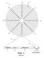
- concentric servo sectors 2 0 - 2 Nare written to a disk 4 which define a plurality of radially-spaced, concentric data tracks 6 as shown in the prior art disk format of FIG. 1 .
- Each data track 6is partitioned into a plurality of data sectors wherein the concentric servo sectors 2 0 - 2 N are considered “embedded” in the data sectors.
- Each servo sector(e.g., servo sector 2 4 ) comprises a preamble 8 for synchronizing gain control and timing recovery, a sync mark 10 for synchronizing to a data field 12 comprising coarse head positioning information such as a track number, and servo bursts 14 which provide fine head positioning information.
- the coarse head position informationis processed to position a head over a target track during a seek operation, and the servo bursts 14 are processed to maintain the head over a centerline of the target track while writing or reading data during a tracking operation.
- external servo writershave been used to write the concentric servo sectors 2 0 - 2 N to the disk surface during manufacturing.
- External servo writersemploy extremely accurate head positioning mechanics, such as a laser interferometer, to ensure the concentric servo sectors 2 0 - 2 N are written at the proper radial location from the outer diameter of the disk to the inner diameter of the disk.
- head positioning mechanicssuch as a laser interferometer
- external servo writersare expensive and require a clean room environment so that a head positioning pin can be inserted into the head disk assembly (HDA) without contaminating the disk.
- HDAhead disk assembly
- U.S. Pat. No. 5,668,679teaches a disk drive which performs a self-servo writing operation by writing a plurality of spiral servo tracks to the disk which are then processed to write the concentric servo sectors along a circular path.
- Each spiral servo trackis written to the disk as a high frequency signal (with missing bits), wherein the position error signal (PES) for tracking is generated relative to time shifts in the detected location of the spiral servo tracks.
- PESposition error signal
- the read signalis rectified and low pass filtered to generate a triangular envelope signal representing a spiral servo track crossing, wherein the location of the spiral servo track is detected by detecting a peak in the triangular envelope signal relative to a clock synchronized to the rotation of the disk.
- the spiral servo tracks in the '679 patentare written by the control circuitry within each disk drive by controlling the velocity of the head open loop (no feedback during the constant velocity segment of the velocity profile).
- controlling the velocity of the actuator arm open loopmeans that the actual velocity of the head relative to the disk will vary while writing each spiral servo track, as well as vary between each spiral servo track.
- the velocity errors when writing each spiral servo trackleads to tracking and timing errors when writing the concentric servo sectors.
- FIG. 1shows a prior art disk format comprising a plurality of data tracks defined a plurality of embedded servo sectors.
- FIG. 2is a flow diagram according to an embodiment of the present invention wherein concentric servo sectors on a first disk surface are processed to write spiral servo tracks to a second disk surface.
- FIGS. 3A-3Cillustrate the flow diagram of FIG. 2 .
- FIG. 4is a flow diagram according to an embodiment of the present invention wherein spiral servo tracks on a first disk surface are processed to write concentric servo sectors on the first disk surface, and then the concentric servo sectors are processed to write spiral servo tracks to a second disk surface.
- FIGS. 5A-5Dillustrate the flow diagram of FIG. 4 .
- FIG. 6Ashows an external spiral servo writer for writing spiral servo tracks to the disk according to an embodiment of the present invention.
- FIG. 6Bshows spiral servo tracks written to the disk over a partial disk revolution according to an embodiment of the present invention.
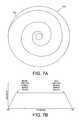
- FIG. 7Aillustrates an embodiment of the present invention wherein each spiral servo track is written over multiple revolutions of the disk.
- FIG. 7Bshows a velocity profile according to an embodiment of the present invention for writing a spiral servo track to a disk.
- FIG. 8Ashows an embodiment of the present invention wherein a servo write clock is synchronized by clocking a modulo-N counter relative to when the sync marks in the spiral servo tracks are detected.
- FIG. 8Bshows an envelope generated by reading the spiral servo track, including the sync marks in the spiral servo track.
- FIG. 9illustrates writing of concentric servo sectors using a servo write clock generated from reading the spiral servo tracks.
- FIGS. 10A-10Cillustrate an embodiment of the present invention wherein a first head connected to an actuator arm is used to read concentric servo sectors while a second head connected to the same actuator arm is used to write spiral servo tracks to a second disk surface.
- FIG. 11is a flow diagram according to an embodiment of the present invention wherein spiral servo tracks are propagated across multiple disk surfaces in a daisy chain fashion.
- FIG. 2is a flow diagram according to an embodiment of the present invention.
- Concentric servo sectorsare read across substantially the entire radius of a first disk surface using a first head to generate a read signal (step 16 ).
- the read signalis processed to generate a position error signal (PES) representing a radial location of the first head relative to the first disk surface (step 18 ).
- PESposition error signal
- the PESis processed to generate a control signal applied to the VCM to move a second head radially over a second disk surface (step 20 ) while writing a spiral servo track on the second disk surface (step 22 ).
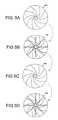
- FIG. 3Aillustrates an embodiment of the present invention wherein a first disk surface 24 A comprises a plurality of concentric servo sectors 26 0 - 26 N forming wedges from the inner to outer diameter of the disk.
- the concentric servo sectors 26 0 - 26 Nare read in order to servo a first head radially over the first disk surface at a predetermined velocity while a second head writes a spiral servo track 28 i to a second disk surface 24 B. This process is repeated in order to write a plurality of spiral servo tracks 28 0 - 28 N to the second disk surface 24 B as shown in FIG. 3B .
- the concentric servo sectors 26 0 - 26 Nmay be recorded on the first disk surface 24 A using any suitable technique.
- the diskis installed into a head disk assembly (HDA) of the disk drive and then the concentric servo sectors 26 0 - 26 N are written to the first disk surface 24 A using an external servo writer.
- a media writerwrites the concentric servo sectors 26 0 - 26 N to the first disk surface 24 A, and then the disk is installed into the HDA of a disk drive.
- the concentric servo sectors 26 0 - 26 Nmay be recorded to the first disk surface 24 A using a magnetic printing technique.
- a plurality of concentric servo sectors 30 0 - 30 Nare written to the second disk surface 24 B ( FIG. 3C ) in response to the spiral servo tracks 28 0 - 28 N . Further details of how the concentric servo sectors 30 0 - 30 N are written in response to the spiral servo tracks 28 0 - 28 N are provided below with reference to FIG. 9 .
- FIG. 4shows a flow diagram according to an embodiment of the present invention which is an extension of the flow diagram of FIG. 2 , wherein spiral servo tracks are written to a first disk surface (step 32 ).
- the spiral servo tracksmay be written using any suitable technique, such as with an external spiral servo writer, media writer, or magnetic printing technique.
- the spiral servo tracksare then read from the first disk surface (step 34 ) in order to write concentric servo sectors to the first disk surface (step 35 ).
- the concentric servo sectors on the first disk surfaceare then processed to write spiral servo tracks to a second disk surface (steps 16 - 22 ).
- FIG. 5Aillustrates an embodiment of the present invention wherein a plurality of spiral servo tracks are written to a first disk surface 24 A which are then processed in order to write a plurality of concentric servo sectors to the first disk surface ( FIG. 5B ). Thereafter, the concentric servo sectors on the first disk surface 24 A are processed to write a plurality of spiral servo tracks to a second disk surface ( FIG. 5C ). The spiral servo tracks on the second disk surface 24 B are then processed to write a plurality of concentric servo sectors on the second disk surface ( FIG. 5D ).
- FIG. 6Ashows an embodiment of the present invention wherein an external spiral servo writer 36 is used to write a plurality of spiral servo tracks 28 0 - 28 N to a first disk surface 24 A of a disk drive 38 , wherein each spiral servo track 28 i comprises a high frequency signal 40 interrupted by a sync mark 42 at a sync mark interval ( FIG. 8B ).
- the disk drive 38comprises control circuitry 44 and a head disk assembly (HDA) 46 comprising the disk, an actuator arm 48 , a head 50 coupled to a distal end of the actuator arm 48 , and a voice coil motor 52 for rotating the actuator arm 48 about a pivot to position the head 50 radially over the disk.
- a write clockis synchronized to the rotation of the disk, and the plurality of spiral servo tracks 28 0 - 28 N are written on the disk at a predetermined circular location determined from the write clock.
- the external spiral servo writer 36comprises a head positioner 54 for actuating a head positioning pin 56 using sensitive positioning circuitry, such as a laser interferometer. While the head positioner 56 moves the head 50 at a predetermined velocity over the stroke of the actuator arm 48 , pattern circuitry 58 generates the data sequence written to the disk for a spiral servo track 28 .
- the external spiral servo writer 36inserts a clock head 60 into the HDA 46 for writing a clock track 62 ( FIG. 6B ) at an outer diameter of the disk.
- the clock head 60then reads the clock track 62 to generate a clock signal 64 processed by timing recovery circuitry 66 to synchronize the write clock 68 for writing the spiral servo tracks 28 0 - 28 N to the disk.
- the timing recovery circuitry 66enables the pattern circuitry 58 at the appropriate time relative to the write clock 68 so that the spiral servo tracks 28 0 - 28 N are written at the appropriate circular location.
- the timing recovery circuitry 66also enables the pattern circuitry 58 relative to the write clock 68 to write the sync marks 42 ( FIG. 8B ) within the spiral servo tracks 28 0 - 28 N at the same circular location from the outer diameter to the inner diameter of the disk.
- the constant interval between sync marks 42(independent of the radial location of the head 50 ) enables the servo write clock to maintain synchronization while writing the concentric servo sectors to the disk.
- each spiral servo track 28 iis written over a partial revolution of the disk. In an alternative embodiment, each spiral servo track 28 i is written over one or more revolutions of the disk.
- FIG. 7Ashows an embodiment wherein each spiral servo track 28 i is written over multiple revolutions of the disk. The length of each spiral servo track 28 i (and number of revolutions spanned) is determined by the velocity of the actuator arm 48 as controlled by the VCM 52 in response to a velocity profile an example of which is shown in FIG. 7B . A velocity error signal (derivative of the PES) relative to the velocity profile is generated in response to the concentric servo sectors written on the first disk surface 24 A.
- the head positioning pin 56 and clock head 60are removed from the HDA 46 and the concentric servo sectors are written to the first disk surface 24 A during a “fill operation”.
- the control circuitry 44 within the disk drive 38is used to process the spiral servo tracks 28 0 - 28 N in order to write the concentric servo sectors.
- an external concentric servo writeris used to process the spiral servo tracks 28 0 - 28 N in order to write the concentric servo sectors to the first disk surface 24 A.
- FIG. 8Billustrates an envelope of the read signal as the head 50 passes over a spiral servo track 28 i .
- the read signal representing the spiral servo trackcomprises high frequency transitions 40 interrupted by sync marks 42 .
- the envelopewill shift (left or right) while the sync marks 42 remain fixed.
- the shift in the envelope (detected from the high frequency signal 40 ) relative to the sync marks 42provides the off-track information (position error signal or PES) for servoing the head 50 .
- FIG. 8Ashows an embodiment of the present invention wherein a saw-tooth waveform 70 is generated by clocking a modulo-N counter with the servo write clock, wherein the frequency of the servo write clock is adjusted until the sync marks 42 in the spiral servo tracks 28 0 - 28 N are detected at a target modulo-N count value.
- the servo write clockmay be generated using any suitable circuitry, such as a phase locked loop (PLL).
- PLLphase locked loop
- the value of the modulo-N counterrepresents the phase error for adjusting the PLL.
- the PLLis updated when any one of the sync marks 42 within the envelope is detected.
- the multiple sync marks 42 in each envelopeprovides redundancy so that the PLL is still updated if one or more of the sync marks 42 are missed due to noise in the read signal.
- the servo write clockis coarsely locked to the desired frequency for writing concentric servo sectors to the disk.
- the servo write clockis further synchronized by generating a timing recovery measurement from the high frequency signal 40 between the sync marks 42 in the spiral servo tracks 28 0 - 28 N . Synchronizing the servo write clock to the high frequency signal 40 helps maintain proper radial alignment (phase coherency) of the Gray coded track addresses in the concentric servo sectors.
- the timing recovery measurementmay be generated in any suitable manner.
- the servo write clockis used to sample the high frequency signal 40 and the signal sample values are processed to generate the timing recovery measurement.
- the timing recovery measurementadjusts the phase of the servo write clock (PLL) so that the high frequency signal 40 is sampled synchronously. In this manner, the sync marks 42 provide a coarse timing recovery measurement and the high frequency signal 40 provides a fine timing recovery measurement for maintaining synchronization of the servo write clock.
- PLLphase of the servo write clock
- FIG. 9illustrates how concentric servo sectors 72 0 - 72 N are written to a disk surface after synchronizing the servo write clock in response to the high frequency signal 40 and the sync marks 42 in the spiral servo tracks 28 0 - 28 N .
- the dashed linesrepresent the centerlines of the data tracks.
- the sync marks in the spiral servo tracks 28 0 - 28 Nmay be written so that there is a shift of two sync marks 42 in the envelope ( FIG. 8B ) between data tracks.
- the sync marks 42 in the spiral servo tracks 28 0 - 28 Nare written so that there is a shift of N sync marks in the envelope between data tracks.
- the data tracksare narrower than the spiral servo tracks 28 , however, in an alternative embodiment the data tracks are wider than or proximate the width of the spiral servo tracks 28 i .
- the concentric servo sectors 72 0 - 72 Nare written to the disk surface using the servo write clock.
- Write circuitryis enabled when the modulo-N counter reaches a predetermined value, wherein the servo write clock clocks the write circuitry to write the concentric servo sector 72 to the disk surface.
- the spiral servo tracks 28 0 - 28 N on the diskare processed in an interleaved manner to account for the concentric servo sectors 72 0 - 72 N overwriting a spiral servo track. For example, when writing the concentric servo sectors 72 1 to the disk, spiral servo track 28 2 is processed initially to generate the PES tracking error and the timing recovery measurement.
- spiral servo track 28 3is processed to generate the PES tracking error and the timing recovery measurement.
- the spiral servo tracks 28are written as pairs to facilitate the interleave processing; however, the spiral servo tracks may be written using any suitable spacing (e.g., equal spacing) while still implementing the interleaving aspect.
- the diskcomprises only one set of spiral servo tracks 28 0 - 28 N all of which are processed to servo the head (except the spiral servo track being overwritten).
- FIG. 10Aillustrates an embodiment of the present invention wherein the disk drive comprises a plurality of disk surfaces 24 A- 24 F, and a plurality of actuator arms 48 A- 48 C having heads for accessing each disk surface 24 A- 24 F.
- one of the disk surfaces corresponding to an actuator armis written with concentric servo sectors used to write spiral servo tracks to the other disk surface corresponding to the actuator arm.
- disk surface 24 Ais written with concentric servo sectors that are used to write spiral servo tracks to disk surface 24 B.
- the spiral servo tracksare then processed to write concentric servo sectors to disk surface 24 B.
- disk surface 24 Fis written with concentric servo sectors that are used to write spiral servo tracks to disk surface 24 E.
- the spiral servo tracksare then processed to write concentric servo sectors to disk surface 24 E.
- FIG. 11shows a flow diagram according to another embodiment of the present invention wherein the spiral servo tracks are propagated in a daisy chain fashion.
- Concentric servo sectors written to a first disk surfaceare read (step 74 ) in order to servo the heads across the disk surfaces (step 76 ) while writing spiral servo tracks to a second disk surface (step 78 ).
- the spiral servo tracksare processed to write concentric servo sectors to the second disk surface (step 80 ).
- the concentric servo sectorsare read from the second disk surface (step 82 ) in order to servo the heads across the disk surfaces (step 84 ) while writing spiral servo tracks to a third disk surface (step 86 ).
- the spiral servo tracksare processed to write concentric servo sectors to the third disk surface (step 88 ).
- This daisy chain processrepeats for any suitable number of disk surfaces, and in one embodiment, there may be multiple daisy chains corresponding to different sequences of disk surfaces.
- the headsmay be servoed in response to concentric servo sectors written on one of the disk surfaces in any suitable manner when writing spiral servo tracks to another disk surface.
- the servo algorithm for seeking the heads across the disk surfaces during normal operationis used to servo the heads while writing a spiral servo track.
- the normal seek algorithmmay control the velocity of the VCM relative to a velocity profile such as shown in FIG. 7B .
- control circuitrymay be implemented within a read channel integrated circuit, or in a component separate from the read channel, such as a disk controller, or certain steps described above may be performed by a read channel and others by a disk controller.
- the read channel and disk controllerare implemented as separate integrated circuits, and in an alternative embodiment they are fabricated into a single integrated circuit or system on a chip (SOC).
- the control circuitrymay include a suitable preamp circuit implemented as a separate integrated circuit, integrated into the read channel or disk controller circuit, or integrated into an SOC.
- control circuitrycomprises a microprocessor executing instructions, the instructions being operable to cause the microprocessor to perform the steps of the flow diagrams described herein.
- the instructionsmay be stored in any computer-readable medium. In one embodiment, they may be stored on a non-volatile semiconductor memory external to the microprocessor, or integrated with the microprocessor in a SOC. In another embodiment, the instructions are stored on the disk and read into a volatile semiconductor memory when the disk drive is powered on. In yet another embodiment, the control circuitry comprises suitable logic circuitry, such as state machine circuitry.
Landscapes
- Moving Of The Head To Find And Align With The Track (AREA)
Abstract
Description
Claims (20)
Priority Applications (1)
| Application Number | Priority Date | Filing Date | Title |
|---|---|---|---|
| US12/136,207US7843662B1 (en) | 2008-06-10 | 2008-06-10 | Servoing on concentric servo sectors of a first disk surface to write a spiral servo track to a second disk surface |
Applications Claiming Priority (1)
| Application Number | Priority Date | Filing Date | Title |
|---|---|---|---|
| US12/136,207US7843662B1 (en) | 2008-06-10 | 2008-06-10 | Servoing on concentric servo sectors of a first disk surface to write a spiral servo track to a second disk surface |
Publications (1)
| Publication Number | Publication Date |
|---|---|
| US7843662B1true US7843662B1 (en) | 2010-11-30 |
Family
ID=43215647
Family Applications (1)
| Application Number | Title | Priority Date | Filing Date |
|---|---|---|---|
| US12/136,207Expired - Fee RelatedUS7843662B1 (en) | 2008-06-10 | 2008-06-10 | Servoing on concentric servo sectors of a first disk surface to write a spiral servo track to a second disk surface |
Country Status (1)
| Country | Link |
|---|---|
| US (1) | US7843662B1 (en) |
Cited By (116)
| Publication number | Priority date | Publication date | Assignee | Title |
|---|---|---|---|---|
| US8537486B2 (en) | 2011-08-10 | 2013-09-17 | Western Digital Technologies, Inc. | Disk drive writing spiral tracks on a slave surface using repeatable runout compensation for a master surface |
| US8576506B1 (en) | 2012-06-21 | 2013-11-05 | Western Digital Technologies, Inc. | Disk drive estimating reader/writer gap across servo zones |
| US8634154B1 (en) | 2011-08-08 | 2014-01-21 | Western Digital Technologies, Inc. | Disk drive writing a sync mark seam in a bootstrap spiral track |
| US8634283B1 (en)* | 2011-08-08 | 2014-01-21 | Western Digital Technologies, Inc. | Disk drive performing in-drive spiral track writing |
| US8724245B1 (en) | 2012-06-21 | 2014-05-13 | Western Digital Technologies, Inc. | Disk drive employing overlapping servo zones to facilitate servo zone crossing |
| US8743504B1 (en) | 2012-07-25 | 2014-06-03 | Western Digital Technologies, Inc. | Servoing on zoned concentric servo sectors of a first disk surface to write a spiral servo track to a second disk surface |
| US8780477B1 (en) | 2012-06-21 | 2014-07-15 | Western Digital Technologies, Inc. | Disk drive adjusting servo timing to compensate for transient when crossing a servo zone boundary |
| US8824081B1 (en) | 2012-03-13 | 2014-09-02 | Western Digital Technologies, Inc. | Disk drive employing radially coherent reference pattern for servo burst demodulation and fly height measurement |
| US8830617B1 (en) | 2013-05-30 | 2014-09-09 | Western Digital Technologies, Inc. | Disk drive adjusting state estimator to compensate for unreliable servo data |
| US8861126B1 (en) | 2011-09-20 | 2014-10-14 | Western Digital Technologies, Inc. | Disk drive detecting when head is on ramp |
| US8861123B1 (en) | 2012-09-25 | 2014-10-14 | Western Digital Technologies, Inc. | Disk drive servoing on first disk surface while erasing second disk surface |
| US8879191B1 (en) | 2012-11-14 | 2014-11-04 | Western Digital Technologies, Inc. | Disk drive modifying rotational position optimization algorithm to achieve target performance for limited stroke |
| US8891194B1 (en) | 2013-05-14 | 2014-11-18 | Western Digital Technologies, Inc. | Disk drive iteratively adapting correction value that compensates for non-linearity of head |
| US8891191B1 (en) | 2014-05-06 | 2014-11-18 | Western Digital Technologies, Inc. | Data storage device initializing read signal gain to detect servo seed pattern |
| US8896957B1 (en) | 2013-05-10 | 2014-11-25 | Western Digital Technologies, Inc. | Disk drive performing spiral scan of disk surface to detect residual data |
| US8902538B1 (en) | 2013-03-29 | 2014-12-02 | Western Digital Technologies, Inc. | Disk drive detecting crack in microactuator |
| US8902539B1 (en) | 2014-05-13 | 2014-12-02 | Western Digital Technologies, Inc. | Data storage device reducing seek power consumption |
| US8913342B1 (en) | 2014-03-21 | 2014-12-16 | Western Digital Technologies, Inc. | Data storage device adjusting range of microactuator digital-to-analog converter based on operating temperature |
| US8917474B1 (en) | 2011-08-08 | 2014-12-23 | Western Digital Technologies, Inc. | Disk drive calibrating a velocity profile prior to writing a spiral track |
| US8917475B1 (en) | 2013-12-20 | 2014-12-23 | Western Digital Technologies, Inc. | Disk drive generating a disk locked clock using radial dependent timing feed-forward compensation |
| US8922937B1 (en) | 2012-04-19 | 2014-12-30 | Western Digital Technologies, Inc. | Disk drive evaluating multiple vibration sensor outputs to enable write-protection |
| US8922931B1 (en) | 2013-05-13 | 2014-12-30 | Western Digital Technologies, Inc. | Disk drive releasing variable amount of buffered write data based on sliding window of predicted servo quality |
| US8922940B1 (en) | 2014-05-27 | 2014-12-30 | Western Digital Technologies, Inc. | Data storage device reducing spindle motor voltage boost during power failure |
| US8922938B1 (en) | 2012-11-02 | 2014-12-30 | Western Digital Technologies, Inc. | Disk drive filtering disturbance signal and error signal for adaptive feed-forward compensation |
| US8929021B1 (en) | 2012-03-27 | 2015-01-06 | Western Digital Technologies, Inc. | Disk drive servo writing from spiral tracks using radial dependent timing feed-forward compensation |
| US8929022B1 (en) | 2012-12-19 | 2015-01-06 | Western Digital Technologies, Inc. | Disk drive detecting microactuator degradation by evaluating frequency component of servo signal |
| US8934186B1 (en) | 2014-03-26 | 2015-01-13 | Western Digital Technologies, Inc. | Data storage device estimating servo zone to reduce size of track address |
| US8937784B1 (en) | 2012-08-01 | 2015-01-20 | Western Digital Technologies, Inc. | Disk drive employing feed-forward compensation and phase shift compensation during seek settling |
| US8941945B1 (en) | 2014-06-06 | 2015-01-27 | Western Digital Technologies, Inc. | Data storage device servoing heads based on virtual servo tracks |
| US8941939B1 (en) | 2013-10-24 | 2015-01-27 | Western Digital Technologies, Inc. | Disk drive using VCM BEMF feed-forward compensation to write servo data to a disk |
| US8947819B1 (en) | 2012-08-28 | 2015-02-03 | Western Digital Technologies, Inc. | Disk drive implementing hysteresis for primary shock detector based on a more sensitive secondary shock detector |
| US8953278B1 (en) | 2011-11-16 | 2015-02-10 | Western Digital Technologies, Inc. | Disk drive selecting disturbance signal for feed-forward compensation |
| US8953271B1 (en) | 2013-05-13 | 2015-02-10 | Western Digital Technologies, Inc. | Disk drive compensating for repeatable run out selectively per zone |
| US8958169B1 (en) | 2014-06-11 | 2015-02-17 | Western Digital Technologies, Inc. | Data storage device re-qualifying state estimator while decelerating head |
| US8970979B1 (en) | 2013-12-18 | 2015-03-03 | Western Digital Technologies, Inc. | Disk drive determining frequency response of actuator near servo sample frequency |
| US8982490B1 (en) | 2014-04-24 | 2015-03-17 | Western Digital Technologies, Inc. | Data storage device reading first spiral track while simultaneously writing second spiral track |
| US8982501B1 (en) | 2014-09-22 | 2015-03-17 | Western Digital Technologies, Inc. | Data storage device compensating for repeatable disturbance when commutating a spindle motor |
| US8995075B1 (en) | 2012-06-21 | 2015-03-31 | Western Digital Technologies, Inc. | Disk drive adjusting estimated servo state to compensate for transient when crossing a servo zone boundary |
| US8995082B1 (en) | 2011-06-03 | 2015-03-31 | Western Digital Technologies, Inc. | Reducing acoustic noise in a disk drive when exiting idle mode |
| US9001454B1 (en) | 2013-04-12 | 2015-04-07 | Western Digital Technologies, Inc. | Disk drive adjusting phase of adaptive feed-forward controller when reconfiguring servo loop |
| US9007714B1 (en) | 2014-07-18 | 2015-04-14 | Western Digital Technologies Inc. | Data storage device comprising slew rate anti-windup compensation for microactuator |
| US9013825B1 (en) | 2014-03-24 | 2015-04-21 | Western Digital Technologies, Inc. | Electronic system with vibration management mechanism and method of operation thereof |
| US9013824B1 (en) | 2014-06-04 | 2015-04-21 | Western Digital Technologies, Inc. | Data storage device comprising dual read sensors and dual servo channels to improve servo demodulation |
| US9026728B1 (en) | 2013-06-06 | 2015-05-05 | Western Digital Technologies, Inc. | Disk drive applying feed-forward compensation when writing consecutive data tracks |
| US9025269B1 (en) | 2014-01-02 | 2015-05-05 | Western Digital Technologies, Inc. | Disk drive compensating for cycle slip of disk locked clock when reading mini-wedge |
| US9047901B1 (en) | 2013-05-28 | 2015-06-02 | Western Digital Technologies, Inc. | Disk drive measuring spiral track error by measuring a slope of a spiral track across a disk radius |
| US9047932B1 (en) | 2014-03-21 | 2015-06-02 | Western Digital Technologies, Inc. | Data storage device adjusting a power loss threshold based on samples of supply voltage |
| US9047919B1 (en) | 2013-03-12 | 2015-06-02 | Western Digitial Technologies, Inc. | Disk drive initializing servo read channel by reading data preceding servo preamble during access operation |
| US9053726B1 (en) | 2014-01-29 | 2015-06-09 | Western Digital Technologies, Inc. | Data storage device on-line adapting disturbance observer filter |
| US9053712B1 (en) | 2014-05-07 | 2015-06-09 | Western Digital Technologies, Inc. | Data storage device reading servo sector while writing data sector |
| US9053727B1 (en) | 2014-06-02 | 2015-06-09 | Western Digital Technologies, Inc. | Disk drive opening spiral crossing window based on DC and AC spiral track error |
| US9058834B1 (en) | 2013-11-08 | 2015-06-16 | Western Digital Technologies, Inc. | Power architecture for low power modes in storage devices |
| US9058826B1 (en) | 2014-02-13 | 2015-06-16 | Western Digital Technologies, Inc. | Data storage device detecting free fall condition from disk speed variations |
| US9058827B1 (en) | 2013-06-25 | 2015-06-16 | Western Digitial Technologies, Inc. | Disk drive optimizing filters based on sensor signal and disturbance signal for adaptive feed-forward compensation |
| US9064537B1 (en) | 2013-09-13 | 2015-06-23 | Western Digital Technologies, Inc. | Disk drive measuring radial offset between heads by detecting a difference between ramp contact |
| US9076471B1 (en) | 2013-07-31 | 2015-07-07 | Western Digital Technologies, Inc. | Fall detection scheme using FFS |
| US9076473B1 (en) | 2014-08-12 | 2015-07-07 | Western Digital Technologies, Inc. | Data storage device detecting fly height instability of head during load operation based on microactuator response |
| US9076490B1 (en) | 2012-12-12 | 2015-07-07 | Western Digital Technologies, Inc. | Disk drive writing radial offset spiral servo tracks by reading spiral seed tracks |
| US9076472B1 (en) | 2014-08-21 | 2015-07-07 | Western Digital (Fremont), Llc | Apparatus enabling writing servo data when disk reaches target rotation speed |
| US9093105B2 (en) | 2011-12-09 | 2015-07-28 | Western Digital Technologies, Inc. | Disk drive charging capacitor using motor supply voltage during power failure |
| US9099147B1 (en) | 2014-09-22 | 2015-08-04 | Western Digital Technologies, Inc. | Data storage device commutating a spindle motor using closed-loop rotation phase alignment |
| US9111575B1 (en) | 2014-10-23 | 2015-08-18 | Western Digital Technologies, Inc. | Data storage device employing adaptive feed-forward control in timing loop to compensate for vibration |
| US9129630B1 (en) | 2014-12-16 | 2015-09-08 | Western Digital Technologies, Inc. | Data storage device employing full servo sectors on first disk surface and mini servo sectors on second disk surface |
| US9142235B1 (en) | 2009-10-27 | 2015-09-22 | Western Digital Technologies, Inc. | Disk drive characterizing microactuator by injecting sinusoidal disturbance and evaluating feed-forward compensation values |
| US9141177B1 (en) | 2014-03-21 | 2015-09-22 | Western Digital Technologies, Inc. | Data storage device employing glitch compensation for power loss detection |
| US9142225B1 (en) | 2014-03-21 | 2015-09-22 | Western Digital Technologies, Inc. | Electronic system with actuator control mechanism and method of operation thereof |
| US9142249B1 (en) | 2013-12-06 | 2015-09-22 | Western Digital Technologies, Inc. | Disk drive using timing loop control signal for vibration compensation in servo loop |
| US9147428B1 (en) | 2013-04-24 | 2015-09-29 | Western Digital Technologies, Inc. | Disk drive with improved spin-up control |
| US9147418B1 (en) | 2013-06-20 | 2015-09-29 | Western Digital Technologies, Inc. | Disk drive compensating for microactuator gain variations |
| US9153283B1 (en) | 2014-09-30 | 2015-10-06 | Western Digital Technologies, Inc. | Data storage device compensating for hysteretic response of microactuator |
| US9165583B1 (en) | 2014-10-29 | 2015-10-20 | Western Digital Technologies, Inc. | Data storage device adjusting seek profile based on seek length when ending track is near ramp |
| US9171567B1 (en) | 2014-05-27 | 2015-10-27 | Western Digital Technologies, Inc. | Data storage device employing sliding mode control of spindle motor |
| US9171568B1 (en) | 2014-06-25 | 2015-10-27 | Western Digital Technologies, Inc. | Data storage device periodically re-initializing spindle motor commutation sequence based on timing data |
| US9208810B1 (en) | 2014-04-24 | 2015-12-08 | Western Digital Technologies, Inc. | Data storage device attenuating interference from first spiral track when reading second spiral track |
| US9208815B1 (en) | 2014-10-09 | 2015-12-08 | Western Digital Technologies, Inc. | Data storage device dynamically reducing coast velocity during seek to reduce power consumption |
| US9208808B1 (en) | 2014-04-22 | 2015-12-08 | Western Digital Technologies, Inc. | Electronic system with unload management mechanism and method of operation thereof |
| US9214175B1 (en) | 2015-03-16 | 2015-12-15 | Western Digital Technologies, Inc. | Data storage device configuring a gain of a servo control system for actuating a head over a disk |
| US9230592B1 (en) | 2014-12-23 | 2016-01-05 | Western Digital Technologies, Inc. | Electronic system with a method of motor spindle bandwidth estimation and calibration thereof |
| US9230593B1 (en) | 2014-12-23 | 2016-01-05 | Western Digital Technologies, Inc. | Data storage device optimizing spindle motor power when transitioning into a power failure mode |
| US9245560B1 (en) | 2015-03-09 | 2016-01-26 | Western Digital Technologies, Inc. | Data storage device measuring reader/writer offset by reading spiral track and concentric servo sectors |
| US9245540B1 (en) | 2014-10-29 | 2016-01-26 | Western Digital Technologies, Inc. | Voice coil motor temperature sensing circuit to reduce catastrophic failure due to voice coil motor coil shorting to ground |
| US9245577B1 (en) | 2015-03-26 | 2016-01-26 | Western Digital Technologies, Inc. | Data storage device comprising spindle motor current sensing with supply voltage noise attenuation |
| US9251823B1 (en) | 2014-12-10 | 2016-02-02 | Western Digital Technologies, Inc. | Data storage device delaying seek operation to avoid thermal asperities |
| US9269386B1 (en) | 2014-01-29 | 2016-02-23 | Western Digital Technologies, Inc. | Data storage device on-line adapting disturbance observer filter |
| US9286925B1 (en) | 2015-03-26 | 2016-03-15 | Western Digital Technologies, Inc. | Data storage device writing multiple burst correction values at the same radial location |
| US9286927B1 (en) | 2014-12-16 | 2016-03-15 | Western Digital Technologies, Inc. | Data storage device demodulating servo burst by computing slope of intermediate integration points |
| US9343094B1 (en) | 2015-03-26 | 2016-05-17 | Western Digital Technologies, Inc. | Data storage device filtering burst correction values before downsampling the burst correction values |
| US9343102B1 (en) | 2015-03-25 | 2016-05-17 | Western Digital Technologies, Inc. | Data storage device employing a phase offset to generate power from a spindle motor during a power failure |
| US9350278B1 (en) | 2014-06-13 | 2016-05-24 | Western Digital Technologies, Inc. | Circuit technique to integrate voice coil motor support elements |
| US9349401B1 (en) | 2014-07-24 | 2016-05-24 | Western Digital Technologies, Inc. | Electronic system with media scan mechanism and method of operation thereof |
| US9355666B1 (en) | 2013-09-30 | 2016-05-31 | Western Digital Technologies, Inc. | Disk drive measuring stroke difference between heads by detecting a difference between ramp contact |
| US9355667B1 (en) | 2014-11-11 | 2016-05-31 | Western Digital Technologies, Inc. | Data storage device saving absolute position at each servo wedge for previous write operations |
| US9355676B1 (en) | 2015-03-25 | 2016-05-31 | Western Digital Technologies, Inc. | Data storage device controlling amplitude and phase of driving voltage to generate power from a spindle motor |
| US9361939B1 (en) | 2014-03-10 | 2016-06-07 | Western Digital Technologies, Inc. | Data storage device characterizing geometry of magnetic transitions |
| US9396751B1 (en) | 2015-06-26 | 2016-07-19 | Western Digital Technologies, Inc. | Data storage device compensating for fabrication tolerances when measuring spindle motor current |
| US9407015B1 (en) | 2014-12-29 | 2016-08-02 | Western Digital Technologies, Inc. | Automatic power disconnect device |
| US9418689B2 (en) | 2014-10-09 | 2016-08-16 | Western Digital Technologies, Inc. | Data storage device generating an operating seek time profile as a function of a base seek time profile |
| US9424871B1 (en) | 2012-09-13 | 2016-08-23 | Western Digital Technologies, Inc. | Disk drive correcting an error in a detected gray code |
| US9424868B1 (en) | 2015-05-12 | 2016-08-23 | Western Digital Technologies, Inc. | Data storage device employing spindle motor driving profile during seek to improve power performance |
| US9437231B1 (en) | 2015-09-25 | 2016-09-06 | Western Digital Technologies, Inc. | Data storage device concurrently controlling and sensing a secondary actuator for actuating a head over a disk |
| US9437237B1 (en) | 2015-02-20 | 2016-09-06 | Western Digital Technologies, Inc. | Method to detect power loss through data storage device spindle speed |
| US9454212B1 (en) | 2014-12-08 | 2016-09-27 | Western Digital Technologies, Inc. | Wakeup detector |
| US9471072B1 (en) | 2013-11-14 | 2016-10-18 | Western Digital Technologies, Inc | Self-adaptive voltage scaling |
| US9484733B1 (en) | 2013-09-11 | 2016-11-01 | Western Digital Technologies, Inc. | Power control module for data storage device |
| CN106251887A (en)* | 2015-06-03 | 2016-12-21 | Hgst荷兰公司 | Automatic servo write enters non-reference head position measurement |
| US9542966B1 (en) | 2015-07-09 | 2017-01-10 | Western Digital Technologies, Inc. | Data storage devices and methods with frequency-shaped sliding mode control |
| US9564162B1 (en) | 2015-12-28 | 2017-02-07 | Western Digital Technologies, Inc. | Data storage device measuring resonant frequency of a shock sensor by applying differential excitation and measuring oscillation |
| US9581978B1 (en) | 2014-12-17 | 2017-02-28 | Western Digital Technologies, Inc. | Electronic system with servo management mechanism and method of operation thereof |
| US9620160B1 (en) | 2015-12-28 | 2017-04-11 | Western Digital Technologies, Inc. | Data storage device measuring resonant frequency of a shock sensor by inserting the shock sensor into an oscillator circuit |
| US9823294B1 (en) | 2013-10-29 | 2017-11-21 | Western Digital Technologies, Inc. | Negative voltage testing methodology and tester |
| US9886285B2 (en) | 2015-03-31 | 2018-02-06 | Western Digital Technologies, Inc. | Communication interface initialization |
| US9899834B1 (en) | 2015-11-18 | 2018-02-20 | Western Digital Technologies, Inc. | Power control module using protection circuit for regulating backup voltage to power load during power fault |
| US9959204B1 (en) | 2015-03-09 | 2018-05-01 | Western Digital Technologies, Inc. | Tracking sequential ranges of non-ordered data |
| US10269385B1 (en) | 2018-06-07 | 2019-04-23 | Western Digital Technologies, Inc. | Data storage device switching disk surfaces to perform seek using spiral track |
| US20190279675A1 (en)* | 2018-03-12 | 2019-09-12 | Kabushiki Kaisha Toshiba | Parallel micro-actuator ssw writing |
| US20230084200A1 (en)* | 2021-09-16 | 2023-03-16 | Kabushiki Kaisha Toshiba | Magnetic disk device and method of writing spiral patterns |
Citations (42)
| Publication number | Priority date | Publication date | Assignee | Title |
|---|---|---|---|---|
| US4107746A (en)* | 1977-10-25 | 1978-08-15 | Control Data Corporation | Continuous spiral mode tracking in a conventional disk drive using concentric servo tracks |
| US5668679A (en) | 1995-12-21 | 1997-09-16 | Quantum Corporation | System for self-servowriting a disk drive |
| US5815485A (en)* | 1993-02-02 | 1998-09-29 | Matsushita Electric Industrial Co., Ltd. | Recording medium, a method for producing the same, a control method using the recording medium, and a recording/reproducing apparatus using the recording medium |
| US6091564A (en)* | 1998-04-30 | 2000-07-18 | Western Digital Corporation | Disk drive with calibration bursts that are recorded on a spiral and method of recording the same |
| US6344942B1 (en) | 1998-07-16 | 2002-02-05 | International Business Machines Corporation | Method and apparatus for absolute track spacing determination for self-servowriting |
| US6411459B1 (en) | 1999-02-22 | 2002-06-25 | Seagate Technology Llc | Advanced servo writing method for hard disc drives |
| US6519107B1 (en) | 1999-09-24 | 2003-02-11 | Maxtor Corporation | Hard disk drive having self-written servo burst patterns |
| US20030086196A1 (en) | 2001-11-08 | 2003-05-08 | Morris Frank Ivan | Method and apparatus for servo track writing by track following on a dedicated servo disk on a fluid spindle bearing |
| US20030099050A1 (en) | 2001-11-27 | 2003-05-29 | Katsuyoshi Kitagawa | Apparatus and method for writing head positioning information to disk medium |
| US6631046B2 (en) | 2000-01-10 | 2003-10-07 | Seagate Technology Llc | Servo track writing using extended copying with head offset |
| US20040160696A1 (en) | 2002-12-05 | 2004-08-19 | Meyer Dallas W. | Self-servo writing using recording head micropositioner |
| US6934112B2 (en) | 2003-03-04 | 2005-08-23 | Fuji Electric Device Technology Co. Ltd. | Method for obtaining head positions in magnetic data writing apparatus |
| US6954318B2 (en) | 2003-03-17 | 2005-10-11 | Fuji Electric Holdings Co., Ltd. | Magnetic data embedding apparatus having checking function |
| US6977791B2 (en) | 2002-03-23 | 2005-12-20 | Kla-Tencor Technologies Corporation | Media servowriting system |
| US6992848B1 (en) | 2002-03-29 | 2006-01-31 | Western Digital Technologies, Inc. | Using an external spiral servo writer to write spiral reference patterns to a disk to facilitate writing product servo bursts to the disk |
| US7016132B2 (en) | 2003-01-27 | 2006-03-21 | Fuji Electric Device Technology Co., Ltd. | Magnetic data embedding system |
| US7057842B2 (en) | 2003-11-10 | 2006-06-06 | Samsung Electronics Co., Ltd. | Method, medium, and apparatus for offline self servo writing and disk drive using the same |
| US7088533B1 (en) | 2002-04-23 | 2006-08-08 | Maxtor Corporation | Method of self-servo writing in a disk drive using a spiral pattern |
| US7113362B1 (en) | 2004-01-31 | 2006-09-26 | Western Digital Technologies, Inc. | Servo writing a disk drive by processing spiral tracks in an interleaved manner |
| US7116511B2 (en) | 2004-07-08 | 2006-10-03 | Matsushita Electric Inductrial Co., Ltd. | Systems and methods for two-step reference pattern self-servowriting |
| US7133239B1 (en)* | 2000-05-09 | 2006-11-07 | Maxtor Corporation | Methods and apparatuses for writing spiral servo patterns onto a disk surface |
| US7133240B2 (en) | 2004-07-08 | 2006-11-07 | Matsushita Electric Industrial Co., Ltd. | Systems and methods for two-step self-servowriting without removing timing eccentricity on intermediate patterns |
| US7133233B1 (en) | 2000-10-24 | 2006-11-07 | Maxtor Corporation | Disk drive with read while write capability |
| US7139144B1 (en)* | 2000-08-04 | 2006-11-21 | Maxtor Corporation | Method and apparatus for writing spiral servo information by modifying existing servo track writing equipment |
| US20070047132A1 (en)* | 2005-08-31 | 2007-03-01 | Kabushiki Kaisha Toshiba | Method and apparatus for writing servo information |
| US20070081268A1 (en) | 2005-10-11 | 2007-04-12 | Samsung Electronics Co., Ltd. | Method of writing a reference servo signal of hard disk drive and apparatus suitable therefor |
| US7206157B2 (en) | 2004-07-08 | 2007-04-17 | Matsushita Electric Industrial Co., Ltd. | Systems and methods for two-step self-servowriting using optimal intermediate pattern |
| US7212369B1 (en) | 2003-08-15 | 2007-05-01 | Maxtor Corporation | Method and apparatus for performing a spiral self-servo write operation in a disk drive using an auto detection scheme |
| US7230789B1 (en) | 2004-04-08 | 2007-06-12 | Maxtor Corporation | Method and apparatus for performing a self-servo write operation in a disk drive using spiral servo information |
| US20070195450A1 (en) | 2006-02-20 | 2007-08-23 | Marvell International Ltd. | Method for improved insitu spiral writing |
| US20070211367A1 (en) | 2006-03-08 | 2007-09-13 | Broadcom Corporation, A California Corporation | Method for establishing and maintaining radial position for hard disk drive self servo write without seed wedges |
| US20070211369A1 (en) | 2006-03-06 | 2007-09-13 | Maxtor Corporation | Self-writeing of servo patterns |
| US7301717B1 (en) | 2004-07-30 | 2007-11-27 | Western Digital Technologies, Inc. | Servo writing a disk drive by integrating a spiral track read signal |
| US7307807B1 (en) | 2003-09-23 | 2007-12-11 | Marvell International Ltd. | Disk servo pattern writing |
| US7312943B2 (en) | 2005-09-28 | 2007-12-25 | Broadcom Corporation | Read write (RW) head position control for self servo writing process |
| US20080002279A1 (en) | 2006-06-30 | 2008-01-03 | Kabushiki Kaisha Toshiba | Method and apparatus for writing a spiral servo pattern on a disk in a disk drive |
| US20080239556A1 (en)* | 2007-03-30 | 2008-10-02 | Toshiba America Information Systems, Inc. | Linearizing position error signal using spiral servo information |
| US7433143B1 (en)* | 2004-09-17 | 2008-10-07 | Western Digital Technologies, Inc. | Adjusting track density by changing slope of spiral tracks used to servo write a disk drive |
| US7499234B1 (en)* | 2003-06-02 | 2009-03-03 | Maxtor Corporation | Method and apparatus for modifying spiral profile using reference tracks written onto a disk surface of a disk drive |
| US7505223B1 (en)* | 2007-09-05 | 2009-03-17 | Western Digital Technologies, Inc. | Compensating for non-linear thermal expansion when writing spiral tracks to a disk of a disk drive |
| US20090086357A1 (en)* | 2007-09-28 | 2009-04-02 | Toshiba America Information Systems, Inc. | In drive written spirals for self servo writing |
| US7561359B1 (en)* | 2003-06-02 | 2009-07-14 | Maxtor Corporation | Spiral servo patterns with absolute reference point |
- 2008
- 2008-06-10USUS12/136,207patent/US7843662B1/ennot_activeExpired - Fee Related
Patent Citations (44)
| Publication number | Priority date | Publication date | Assignee | Title |
|---|---|---|---|---|
| US4107746A (en)* | 1977-10-25 | 1978-08-15 | Control Data Corporation | Continuous spiral mode tracking in a conventional disk drive using concentric servo tracks |
| US5815485A (en)* | 1993-02-02 | 1998-09-29 | Matsushita Electric Industrial Co., Ltd. | Recording medium, a method for producing the same, a control method using the recording medium, and a recording/reproducing apparatus using the recording medium |
| US5668679A (en) | 1995-12-21 | 1997-09-16 | Quantum Corporation | System for self-servowriting a disk drive |
| US6091564A (en)* | 1998-04-30 | 2000-07-18 | Western Digital Corporation | Disk drive with calibration bursts that are recorded on a spiral and method of recording the same |
| US6344942B1 (en) | 1998-07-16 | 2002-02-05 | International Business Machines Corporation | Method and apparatus for absolute track spacing determination for self-servowriting |
| US6411459B1 (en) | 1999-02-22 | 2002-06-25 | Seagate Technology Llc | Advanced servo writing method for hard disc drives |
| US6519107B1 (en) | 1999-09-24 | 2003-02-11 | Maxtor Corporation | Hard disk drive having self-written servo burst patterns |
| US6631046B2 (en) | 2000-01-10 | 2003-10-07 | Seagate Technology Llc | Servo track writing using extended copying with head offset |
| US7133239B1 (en)* | 2000-05-09 | 2006-11-07 | Maxtor Corporation | Methods and apparatuses for writing spiral servo patterns onto a disk surface |
| US7139144B1 (en)* | 2000-08-04 | 2006-11-21 | Maxtor Corporation | Method and apparatus for writing spiral servo information by modifying existing servo track writing equipment |
| US7133233B1 (en) | 2000-10-24 | 2006-11-07 | Maxtor Corporation | Disk drive with read while write capability |
| US7158330B2 (en) | 2001-11-08 | 2007-01-02 | Samsung Electronics Co., Ltd. | Method and apparatus for servo track writing by track following on a dedicated servo disk on a fluid spindle bearing |
| US20030086196A1 (en) | 2001-11-08 | 2003-05-08 | Morris Frank Ivan | Method and apparatus for servo track writing by track following on a dedicated servo disk on a fluid spindle bearing |
| US20030099050A1 (en) | 2001-11-27 | 2003-05-29 | Katsuyoshi Kitagawa | Apparatus and method for writing head positioning information to disk medium |
| US6977791B2 (en) | 2002-03-23 | 2005-12-20 | Kla-Tencor Technologies Corporation | Media servowriting system |
| US6992848B1 (en) | 2002-03-29 | 2006-01-31 | Western Digital Technologies, Inc. | Using an external spiral servo writer to write spiral reference patterns to a disk to facilitate writing product servo bursts to the disk |
| US7088533B1 (en) | 2002-04-23 | 2006-08-08 | Maxtor Corporation | Method of self-servo writing in a disk drive using a spiral pattern |
| US20040160696A1 (en) | 2002-12-05 | 2004-08-19 | Meyer Dallas W. | Self-servo writing using recording head micropositioner |
| US7016132B2 (en) | 2003-01-27 | 2006-03-21 | Fuji Electric Device Technology Co., Ltd. | Magnetic data embedding system |
| US6934112B2 (en) | 2003-03-04 | 2005-08-23 | Fuji Electric Device Technology Co. Ltd. | Method for obtaining head positions in magnetic data writing apparatus |
| US6954318B2 (en) | 2003-03-17 | 2005-10-11 | Fuji Electric Holdings Co., Ltd. | Magnetic data embedding apparatus having checking function |
| US7499234B1 (en)* | 2003-06-02 | 2009-03-03 | Maxtor Corporation | Method and apparatus for modifying spiral profile using reference tracks written onto a disk surface of a disk drive |
| US7561359B1 (en)* | 2003-06-02 | 2009-07-14 | Maxtor Corporation | Spiral servo patterns with absolute reference point |
| US7212369B1 (en) | 2003-08-15 | 2007-05-01 | Maxtor Corporation | Method and apparatus for performing a spiral self-servo write operation in a disk drive using an auto detection scheme |
| US7307807B1 (en) | 2003-09-23 | 2007-12-11 | Marvell International Ltd. | Disk servo pattern writing |
| US7057842B2 (en) | 2003-11-10 | 2006-06-06 | Samsung Electronics Co., Ltd. | Method, medium, and apparatus for offline self servo writing and disk drive using the same |
| US7113362B1 (en) | 2004-01-31 | 2006-09-26 | Western Digital Technologies, Inc. | Servo writing a disk drive by processing spiral tracks in an interleaved manner |
| US7230789B1 (en) | 2004-04-08 | 2007-06-12 | Maxtor Corporation | Method and apparatus for performing a self-servo write operation in a disk drive using spiral servo information |
| US7133240B2 (en) | 2004-07-08 | 2006-11-07 | Matsushita Electric Industrial Co., Ltd. | Systems and methods for two-step self-servowriting without removing timing eccentricity on intermediate patterns |
| US7206157B2 (en) | 2004-07-08 | 2007-04-17 | Matsushita Electric Industrial Co., Ltd. | Systems and methods for two-step self-servowriting using optimal intermediate pattern |
| US7116511B2 (en) | 2004-07-08 | 2006-10-03 | Matsushita Electric Inductrial Co., Ltd. | Systems and methods for two-step reference pattern self-servowriting |
| US7301717B1 (en) | 2004-07-30 | 2007-11-27 | Western Digital Technologies, Inc. | Servo writing a disk drive by integrating a spiral track read signal |
| US7433143B1 (en)* | 2004-09-17 | 2008-10-07 | Western Digital Technologies, Inc. | Adjusting track density by changing slope of spiral tracks used to servo write a disk drive |
| US20070047132A1 (en)* | 2005-08-31 | 2007-03-01 | Kabushiki Kaisha Toshiba | Method and apparatus for writing servo information |
| US7312943B2 (en) | 2005-09-28 | 2007-12-25 | Broadcom Corporation | Read write (RW) head position control for self servo writing process |
| US20070081268A1 (en) | 2005-10-11 | 2007-04-12 | Samsung Electronics Co., Ltd. | Method of writing a reference servo signal of hard disk drive and apparatus suitable therefor |
| US7333286B2 (en) | 2005-10-11 | 2008-02-19 | Samsung Electronics Co., Ltd. | Method of writing a reference servo signal of hard disk drive and apparatus suitable therefor |
| US20070195450A1 (en) | 2006-02-20 | 2007-08-23 | Marvell International Ltd. | Method for improved insitu spiral writing |
| US20070211369A1 (en) | 2006-03-06 | 2007-09-13 | Maxtor Corporation | Self-writeing of servo patterns |
| US20070211367A1 (en) | 2006-03-08 | 2007-09-13 | Broadcom Corporation, A California Corporation | Method for establishing and maintaining radial position for hard disk drive self servo write without seed wedges |
| US20080002279A1 (en) | 2006-06-30 | 2008-01-03 | Kabushiki Kaisha Toshiba | Method and apparatus for writing a spiral servo pattern on a disk in a disk drive |
| US20080239556A1 (en)* | 2007-03-30 | 2008-10-02 | Toshiba America Information Systems, Inc. | Linearizing position error signal using spiral servo information |
| US7505223B1 (en)* | 2007-09-05 | 2009-03-17 | Western Digital Technologies, Inc. | Compensating for non-linear thermal expansion when writing spiral tracks to a disk of a disk drive |
| US20090086357A1 (en)* | 2007-09-28 | 2009-04-02 | Toshiba America Information Systems, Inc. | In drive written spirals for self servo writing |
Cited By (126)
| Publication number | Priority date | Publication date | Assignee | Title |
|---|---|---|---|---|
| US9142235B1 (en) | 2009-10-27 | 2015-09-22 | Western Digital Technologies, Inc. | Disk drive characterizing microactuator by injecting sinusoidal disturbance and evaluating feed-forward compensation values |
| US8995082B1 (en) | 2011-06-03 | 2015-03-31 | Western Digital Technologies, Inc. | Reducing acoustic noise in a disk drive when exiting idle mode |
| US8634154B1 (en) | 2011-08-08 | 2014-01-21 | Western Digital Technologies, Inc. | Disk drive writing a sync mark seam in a bootstrap spiral track |
| US8634283B1 (en)* | 2011-08-08 | 2014-01-21 | Western Digital Technologies, Inc. | Disk drive performing in-drive spiral track writing |
| US8917474B1 (en) | 2011-08-08 | 2014-12-23 | Western Digital Technologies, Inc. | Disk drive calibrating a velocity profile prior to writing a spiral track |
| US8537486B2 (en) | 2011-08-10 | 2013-09-17 | Western Digital Technologies, Inc. | Disk drive writing spiral tracks on a slave surface using repeatable runout compensation for a master surface |
| US8861126B1 (en) | 2011-09-20 | 2014-10-14 | Western Digital Technologies, Inc. | Disk drive detecting when head is on ramp |
| US8953278B1 (en) | 2011-11-16 | 2015-02-10 | Western Digital Technologies, Inc. | Disk drive selecting disturbance signal for feed-forward compensation |
| US9093105B2 (en) | 2011-12-09 | 2015-07-28 | Western Digital Technologies, Inc. | Disk drive charging capacitor using motor supply voltage during power failure |
| US9390749B2 (en) | 2011-12-09 | 2016-07-12 | Western Digital Technologies, Inc. | Power failure management in disk drives |
| US8824081B1 (en) | 2012-03-13 | 2014-09-02 | Western Digital Technologies, Inc. | Disk drive employing radially coherent reference pattern for servo burst demodulation and fly height measurement |
| US8929021B1 (en) | 2012-03-27 | 2015-01-06 | Western Digital Technologies, Inc. | Disk drive servo writing from spiral tracks using radial dependent timing feed-forward compensation |
| US8934191B1 (en) | 2012-03-27 | 2015-01-13 | Western Digital Technologies, Inc. | Disk drive generating a disk locked clock using radial dependent timing feed-forward compensation |
| US8922937B1 (en) | 2012-04-19 | 2014-12-30 | Western Digital Technologies, Inc. | Disk drive evaluating multiple vibration sensor outputs to enable write-protection |
| US9454989B1 (en) | 2012-06-21 | 2016-09-27 | Western Digital Technologies, Inc. | Disk drive adjusting estimated servo state to compensate for transient when crossing a servo zone boundary |
| US8576506B1 (en) | 2012-06-21 | 2013-11-05 | Western Digital Technologies, Inc. | Disk drive estimating reader/writer gap across servo zones |
| US8724245B1 (en) | 2012-06-21 | 2014-05-13 | Western Digital Technologies, Inc. | Disk drive employing overlapping servo zones to facilitate servo zone crossing |
| US8995075B1 (en) | 2012-06-21 | 2015-03-31 | Western Digital Technologies, Inc. | Disk drive adjusting estimated servo state to compensate for transient when crossing a servo zone boundary |
| US8780477B1 (en) | 2012-06-21 | 2014-07-15 | Western Digital Technologies, Inc. | Disk drive adjusting servo timing to compensate for transient when crossing a servo zone boundary |
| US8743504B1 (en) | 2012-07-25 | 2014-06-03 | Western Digital Technologies, Inc. | Servoing on zoned concentric servo sectors of a first disk surface to write a spiral servo track to a second disk surface |
| US8937784B1 (en) | 2012-08-01 | 2015-01-20 | Western Digital Technologies, Inc. | Disk drive employing feed-forward compensation and phase shift compensation during seek settling |
| US8947819B1 (en) | 2012-08-28 | 2015-02-03 | Western Digital Technologies, Inc. | Disk drive implementing hysteresis for primary shock detector based on a more sensitive secondary shock detector |
| US9424871B1 (en) | 2012-09-13 | 2016-08-23 | Western Digital Technologies, Inc. | Disk drive correcting an error in a detected gray code |
| US8861123B1 (en) | 2012-09-25 | 2014-10-14 | Western Digital Technologies, Inc. | Disk drive servoing on first disk surface while erasing second disk surface |
| US8922938B1 (en) | 2012-11-02 | 2014-12-30 | Western Digital Technologies, Inc. | Disk drive filtering disturbance signal and error signal for adaptive feed-forward compensation |
| US8879191B1 (en) | 2012-11-14 | 2014-11-04 | Western Digital Technologies, Inc. | Disk drive modifying rotational position optimization algorithm to achieve target performance for limited stroke |
| US9076490B1 (en) | 2012-12-12 | 2015-07-07 | Western Digital Technologies, Inc. | Disk drive writing radial offset spiral servo tracks by reading spiral seed tracks |
| US8929022B1 (en) | 2012-12-19 | 2015-01-06 | Western Digital Technologies, Inc. | Disk drive detecting microactuator degradation by evaluating frequency component of servo signal |
| US9047919B1 (en) | 2013-03-12 | 2015-06-02 | Western Digitial Technologies, Inc. | Disk drive initializing servo read channel by reading data preceding servo preamble during access operation |
| US8902538B1 (en) | 2013-03-29 | 2014-12-02 | Western Digital Technologies, Inc. | Disk drive detecting crack in microactuator |
| US9001454B1 (en) | 2013-04-12 | 2015-04-07 | Western Digital Technologies, Inc. | Disk drive adjusting phase of adaptive feed-forward controller when reconfiguring servo loop |
| US9147428B1 (en) | 2013-04-24 | 2015-09-29 | Western Digital Technologies, Inc. | Disk drive with improved spin-up control |
| US8896957B1 (en) | 2013-05-10 | 2014-11-25 | Western Digital Technologies, Inc. | Disk drive performing spiral scan of disk surface to detect residual data |
| US8922931B1 (en) | 2013-05-13 | 2014-12-30 | Western Digital Technologies, Inc. | Disk drive releasing variable amount of buffered write data based on sliding window of predicted servo quality |
| US8953271B1 (en) | 2013-05-13 | 2015-02-10 | Western Digital Technologies, Inc. | Disk drive compensating for repeatable run out selectively per zone |
| US8891194B1 (en) | 2013-05-14 | 2014-11-18 | Western Digital Technologies, Inc. | Disk drive iteratively adapting correction value that compensates for non-linearity of head |
| US9047901B1 (en) | 2013-05-28 | 2015-06-02 | Western Digital Technologies, Inc. | Disk drive measuring spiral track error by measuring a slope of a spiral track across a disk radius |
| US8830617B1 (en) | 2013-05-30 | 2014-09-09 | Western Digital Technologies, Inc. | Disk drive adjusting state estimator to compensate for unreliable servo data |
| US9026728B1 (en) | 2013-06-06 | 2015-05-05 | Western Digital Technologies, Inc. | Disk drive applying feed-forward compensation when writing consecutive data tracks |
| US9147418B1 (en) | 2013-06-20 | 2015-09-29 | Western Digital Technologies, Inc. | Disk drive compensating for microactuator gain variations |
| US9058827B1 (en) | 2013-06-25 | 2015-06-16 | Western Digitial Technologies, Inc. | Disk drive optimizing filters based on sensor signal and disturbance signal for adaptive feed-forward compensation |
| US9076471B1 (en) | 2013-07-31 | 2015-07-07 | Western Digital Technologies, Inc. | Fall detection scheme using FFS |
| US9484733B1 (en) | 2013-09-11 | 2016-11-01 | Western Digital Technologies, Inc. | Power control module for data storage device |
| US9064537B1 (en) | 2013-09-13 | 2015-06-23 | Western Digital Technologies, Inc. | Disk drive measuring radial offset between heads by detecting a difference between ramp contact |
| US9355666B1 (en) | 2013-09-30 | 2016-05-31 | Western Digital Technologies, Inc. | Disk drive measuring stroke difference between heads by detecting a difference between ramp contact |
| US8941939B1 (en) | 2013-10-24 | 2015-01-27 | Western Digital Technologies, Inc. | Disk drive using VCM BEMF feed-forward compensation to write servo data to a disk |
| US9823294B1 (en) | 2013-10-29 | 2017-11-21 | Western Digital Technologies, Inc. | Negative voltage testing methodology and tester |
| US9058834B1 (en) | 2013-11-08 | 2015-06-16 | Western Digital Technologies, Inc. | Power architecture for low power modes in storage devices |
| US9471072B1 (en) | 2013-11-14 | 2016-10-18 | Western Digital Technologies, Inc | Self-adaptive voltage scaling |
| US9142249B1 (en) | 2013-12-06 | 2015-09-22 | Western Digital Technologies, Inc. | Disk drive using timing loop control signal for vibration compensation in servo loop |
| US8970979B1 (en) | 2013-12-18 | 2015-03-03 | Western Digital Technologies, Inc. | Disk drive determining frequency response of actuator near servo sample frequency |
| US8917475B1 (en) | 2013-12-20 | 2014-12-23 | Western Digital Technologies, Inc. | Disk drive generating a disk locked clock using radial dependent timing feed-forward compensation |
| US9025269B1 (en) | 2014-01-02 | 2015-05-05 | Western Digital Technologies, Inc. | Disk drive compensating for cycle slip of disk locked clock when reading mini-wedge |
| US9053726B1 (en) | 2014-01-29 | 2015-06-09 | Western Digital Technologies, Inc. | Data storage device on-line adapting disturbance observer filter |
| US9269386B1 (en) | 2014-01-29 | 2016-02-23 | Western Digital Technologies, Inc. | Data storage device on-line adapting disturbance observer filter |
| US9058826B1 (en) | 2014-02-13 | 2015-06-16 | Western Digital Technologies, Inc. | Data storage device detecting free fall condition from disk speed variations |
| US9361939B1 (en) | 2014-03-10 | 2016-06-07 | Western Digital Technologies, Inc. | Data storage device characterizing geometry of magnetic transitions |
| US9141177B1 (en) | 2014-03-21 | 2015-09-22 | Western Digital Technologies, Inc. | Data storage device employing glitch compensation for power loss detection |
| US8913342B1 (en) | 2014-03-21 | 2014-12-16 | Western Digital Technologies, Inc. | Data storage device adjusting range of microactuator digital-to-analog converter based on operating temperature |
| US9142225B1 (en) | 2014-03-21 | 2015-09-22 | Western Digital Technologies, Inc. | Electronic system with actuator control mechanism and method of operation thereof |
| US9047932B1 (en) | 2014-03-21 | 2015-06-02 | Western Digital Technologies, Inc. | Data storage device adjusting a power loss threshold based on samples of supply voltage |
| US9013825B1 (en) | 2014-03-24 | 2015-04-21 | Western Digital Technologies, Inc. | Electronic system with vibration management mechanism and method of operation thereof |
| US8934186B1 (en) | 2014-03-26 | 2015-01-13 | Western Digital Technologies, Inc. | Data storage device estimating servo zone to reduce size of track address |
| US9208808B1 (en) | 2014-04-22 | 2015-12-08 | Western Digital Technologies, Inc. | Electronic system with unload management mechanism and method of operation thereof |
| US9208810B1 (en) | 2014-04-24 | 2015-12-08 | Western Digital Technologies, Inc. | Data storage device attenuating interference from first spiral track when reading second spiral track |
| US8982490B1 (en) | 2014-04-24 | 2015-03-17 | Western Digital Technologies, Inc. | Data storage device reading first spiral track while simultaneously writing second spiral track |
| US8891191B1 (en) | 2014-05-06 | 2014-11-18 | Western Digital Technologies, Inc. | Data storage device initializing read signal gain to detect servo seed pattern |
| US9053712B1 (en) | 2014-05-07 | 2015-06-09 | Western Digital Technologies, Inc. | Data storage device reading servo sector while writing data sector |
| US8902539B1 (en) | 2014-05-13 | 2014-12-02 | Western Digital Technologies, Inc. | Data storage device reducing seek power consumption |
| US9171567B1 (en) | 2014-05-27 | 2015-10-27 | Western Digital Technologies, Inc. | Data storage device employing sliding mode control of spindle motor |
| US8922940B1 (en) | 2014-05-27 | 2014-12-30 | Western Digital Technologies, Inc. | Data storage device reducing spindle motor voltage boost during power failure |
| US9053727B1 (en) | 2014-06-02 | 2015-06-09 | Western Digital Technologies, Inc. | Disk drive opening spiral crossing window based on DC and AC spiral track error |
| US9013824B1 (en) | 2014-06-04 | 2015-04-21 | Western Digital Technologies, Inc. | Data storage device comprising dual read sensors and dual servo channels to improve servo demodulation |
| US8941945B1 (en) | 2014-06-06 | 2015-01-27 | Western Digital Technologies, Inc. | Data storage device servoing heads based on virtual servo tracks |
| US8958169B1 (en) | 2014-06-11 | 2015-02-17 | Western Digital Technologies, Inc. | Data storage device re-qualifying state estimator while decelerating head |
| US9350278B1 (en) | 2014-06-13 | 2016-05-24 | Western Digital Technologies, Inc. | Circuit technique to integrate voice coil motor support elements |
| US9171568B1 (en) | 2014-06-25 | 2015-10-27 | Western Digital Technologies, Inc. | Data storage device periodically re-initializing spindle motor commutation sequence based on timing data |
| US9007714B1 (en) | 2014-07-18 | 2015-04-14 | Western Digital Technologies Inc. | Data storage device comprising slew rate anti-windup compensation for microactuator |
| US9349401B1 (en) | 2014-07-24 | 2016-05-24 | Western Digital Technologies, Inc. | Electronic system with media scan mechanism and method of operation thereof |
| US9076473B1 (en) | 2014-08-12 | 2015-07-07 | Western Digital Technologies, Inc. | Data storage device detecting fly height instability of head during load operation based on microactuator response |
| US9076472B1 (en) | 2014-08-21 | 2015-07-07 | Western Digital (Fremont), Llc | Apparatus enabling writing servo data when disk reaches target rotation speed |
| US9099147B1 (en) | 2014-09-22 | 2015-08-04 | Western Digital Technologies, Inc. | Data storage device commutating a spindle motor using closed-loop rotation phase alignment |
| US8982501B1 (en) | 2014-09-22 | 2015-03-17 | Western Digital Technologies, Inc. | Data storage device compensating for repeatable disturbance when commutating a spindle motor |
| US9153283B1 (en) | 2014-09-30 | 2015-10-06 | Western Digital Technologies, Inc. | Data storage device compensating for hysteretic response of microactuator |
| US9418689B2 (en) | 2014-10-09 | 2016-08-16 | Western Digital Technologies, Inc. | Data storage device generating an operating seek time profile as a function of a base seek time profile |
| US9208815B1 (en) | 2014-10-09 | 2015-12-08 | Western Digital Technologies, Inc. | Data storage device dynamically reducing coast velocity during seek to reduce power consumption |
| US9111575B1 (en) | 2014-10-23 | 2015-08-18 | Western Digital Technologies, Inc. | Data storage device employing adaptive feed-forward control in timing loop to compensate for vibration |
| US9165583B1 (en) | 2014-10-29 | 2015-10-20 | Western Digital Technologies, Inc. | Data storage device adjusting seek profile based on seek length when ending track is near ramp |
| US9245540B1 (en) | 2014-10-29 | 2016-01-26 | Western Digital Technologies, Inc. | Voice coil motor temperature sensing circuit to reduce catastrophic failure due to voice coil motor coil shorting to ground |
| US9355667B1 (en) | 2014-11-11 | 2016-05-31 | Western Digital Technologies, Inc. | Data storage device saving absolute position at each servo wedge for previous write operations |
| US9454212B1 (en) | 2014-12-08 | 2016-09-27 | Western Digital Technologies, Inc. | Wakeup detector |
| US9251823B1 (en) | 2014-12-10 | 2016-02-02 | Western Digital Technologies, Inc. | Data storage device delaying seek operation to avoid thermal asperities |
| US9286927B1 (en) | 2014-12-16 | 2016-03-15 | Western Digital Technologies, Inc. | Data storage device demodulating servo burst by computing slope of intermediate integration points |
| US9129630B1 (en) | 2014-12-16 | 2015-09-08 | Western Digital Technologies, Inc. | Data storage device employing full servo sectors on first disk surface and mini servo sectors on second disk surface |
| US9581978B1 (en) | 2014-12-17 | 2017-02-28 | Western Digital Technologies, Inc. | Electronic system with servo management mechanism and method of operation thereof |
| US9230593B1 (en) | 2014-12-23 | 2016-01-05 | Western Digital Technologies, Inc. | Data storage device optimizing spindle motor power when transitioning into a power failure mode |
| US9761266B2 (en) | 2014-12-23 | 2017-09-12 | Western Digital Technologies, Inc. | Data storage device optimizing spindle motor power when transitioning into a power failure mode |
| US9230592B1 (en) | 2014-12-23 | 2016-01-05 | Western Digital Technologies, Inc. | Electronic system with a method of motor spindle bandwidth estimation and calibration thereof |
| US9407015B1 (en) | 2014-12-29 | 2016-08-02 | Western Digital Technologies, Inc. | Automatic power disconnect device |
| US9437237B1 (en) | 2015-02-20 | 2016-09-06 | Western Digital Technologies, Inc. | Method to detect power loss through data storage device spindle speed |
| US9245560B1 (en) | 2015-03-09 | 2016-01-26 | Western Digital Technologies, Inc. | Data storage device measuring reader/writer offset by reading spiral track and concentric servo sectors |
| US9959204B1 (en) | 2015-03-09 | 2018-05-01 | Western Digital Technologies, Inc. | Tracking sequential ranges of non-ordered data |
| US9214175B1 (en) | 2015-03-16 | 2015-12-15 | Western Digital Technologies, Inc. | Data storage device configuring a gain of a servo control system for actuating a head over a disk |
| US9355676B1 (en) | 2015-03-25 | 2016-05-31 | Western Digital Technologies, Inc. | Data storage device controlling amplitude and phase of driving voltage to generate power from a spindle motor |
| US9343102B1 (en) | 2015-03-25 | 2016-05-17 | Western Digital Technologies, Inc. | Data storage device employing a phase offset to generate power from a spindle motor during a power failure |
| US9343094B1 (en) | 2015-03-26 | 2016-05-17 | Western Digital Technologies, Inc. | Data storage device filtering burst correction values before downsampling the burst correction values |
| US9245577B1 (en) | 2015-03-26 | 2016-01-26 | Western Digital Technologies, Inc. | Data storage device comprising spindle motor current sensing with supply voltage noise attenuation |
| US9286925B1 (en) | 2015-03-26 | 2016-03-15 | Western Digital Technologies, Inc. | Data storage device writing multiple burst correction values at the same radial location |
| US9886285B2 (en) | 2015-03-31 | 2018-02-06 | Western Digital Technologies, Inc. | Communication interface initialization |
| US9424868B1 (en) | 2015-05-12 | 2016-08-23 | Western Digital Technologies, Inc. | Data storage device employing spindle motor driving profile during seek to improve power performance |
| CN106251887A (en)* | 2015-06-03 | 2016-12-21 | Hgst荷兰公司 | Automatic servo write enters non-reference head position measurement |
| US9396751B1 (en) | 2015-06-26 | 2016-07-19 | Western Digital Technologies, Inc. | Data storage device compensating for fabrication tolerances when measuring spindle motor current |
| US9542966B1 (en) | 2015-07-09 | 2017-01-10 | Western Digital Technologies, Inc. | Data storage devices and methods with frequency-shaped sliding mode control |
| US9437231B1 (en) | 2015-09-25 | 2016-09-06 | Western Digital Technologies, Inc. | Data storage device concurrently controlling and sensing a secondary actuator for actuating a head over a disk |
| US10127952B2 (en) | 2015-11-18 | 2018-11-13 | Western Digital Technologies, Inc. | Power control module using protection circuit for regulating backup voltage to power load during power fault |
| US9899834B1 (en) | 2015-11-18 | 2018-02-20 | Western Digital Technologies, Inc. | Power control module using protection circuit for regulating backup voltage to power load during power fault |
| US9620160B1 (en) | 2015-12-28 | 2017-04-11 | Western Digital Technologies, Inc. | Data storage device measuring resonant frequency of a shock sensor by inserting the shock sensor into an oscillator circuit |
| US9564162B1 (en) | 2015-12-28 | 2017-02-07 | Western Digital Technologies, Inc. | Data storage device measuring resonant frequency of a shock sensor by applying differential excitation and measuring oscillation |
| US20190279675A1 (en)* | 2018-03-12 | 2019-09-12 | Kabushiki Kaisha Toshiba | Parallel micro-actuator ssw writing |
| US10665257B2 (en)* | 2018-03-12 | 2020-05-26 | Kabushiki Kaisha Toshiba | Parallel micro-actuator SSW writing |
| US11227631B2 (en)* | 2018-03-12 | 2022-01-18 | Kabushiki Kaisha Toshiba | Parallel micro-actuator SSW writing |
| US10269385B1 (en) | 2018-06-07 | 2019-04-23 | Western Digital Technologies, Inc. | Data storage device switching disk surfaces to perform seek using spiral track |
| US20230084200A1 (en)* | 2021-09-16 | 2023-03-16 | Kabushiki Kaisha Toshiba | Magnetic disk device and method of writing spiral patterns |
| CN115831157A (en)* | 2021-09-16 | 2023-03-21 | 株式会社东芝 | Magnetic disk device and method for writing spiral pattern |
| US11735215B2 (en)* | 2021-09-16 | 2023-08-22 | Kabushiki Kaisha Toshiba | Magnetic disk device and method of writing spiral patterns |
| CN115831157B (en)* | 2021-09-16 | 2025-08-05 | 株式会社东芝 | Magnetic disk device and method for writing spiral patterns |
Similar Documents
| Publication | Publication Date | Title |
|---|---|---|
| US7843662B1 (en) | Servoing on concentric servo sectors of a first disk surface to write a spiral servo track to a second disk surface | |
| US7688539B1 (en) | Disk drive self servo writing spiral tracks by propagating bursts | |
| US8451697B1 (en) | Disk drive centering demodulation windows on spiral tracks during a seek operation | |
| US7301717B1 (en) | Servo writing a disk drive by integrating a spiral track read signal | |
| US7839591B1 (en) | Disk drive comprising index spiral track identified by change in sync mark | |
| US8432629B1 (en) | Disk drive centering sync frames on sync marks of a spiral track | |
| US7864481B1 (en) | Evaluating distribution of peak signals representing reference track crossings to compensate for thermal expansion when writing spiral tracks to a disk | |
| US7330327B1 (en) | Servo writing a disk drive by writing discontinuous spiral tracks to prevent overheating | |
| US8498076B1 (en) | Disk drive biasing timing recovery measurements for spiral tracks based on radial location of head | |
| US7457071B1 (en) | Locating an initial servo track in order to servo write a disk drive from spiral tracks | |
| US7453661B1 (en) | Servo writing a disk drive with a controlled overlap near the middle diameter of the disk | |
| US8724253B1 (en) | Disk drive adjusting demodulation window for spiral track using timing feed-forward compensation | |
| US7502195B1 (en) | Compensating for thermal expansion when writing spiral tracks to a disk of a disk drive | |
| US7876523B1 (en) | Disk drive initializing position feedforward compensation with velocity feedforward compensation | |
| US6987636B1 (en) | Adjusting track density over disk radius by changing slope of spiral tracks used to servo write a disk drive | |
| US7489464B1 (en) | Servo writing a disk drive using a secondary actuator to control skew angle | |
| US8711506B1 (en) | Disk drive increasing capacity by adjusting a servo gate during write operations | |
| US7746592B1 (en) | Disk drive detecting defective spiral servo track | |
| US7468855B1 (en) | Servo writing a disk drive from a number of spiral tracks equal to a non-integer multiple of product servo wedges | |
| US7440210B1 (en) | Servo writing a disk drive by writing multi-bit sync marks in spiral tracks for improved servo writing | |
| US7433143B1 (en) | Adjusting track density by changing slope of spiral tracks used to servo write a disk drive | |
| US8634283B1 (en) | Disk drive performing in-drive spiral track writing | |
| US7859782B1 (en) | Selecting highest reliability sync mark in a sync mark window of a spiral servo track crossing | |
| US7688538B1 (en) | Disk drive comprising a disk surface having track addresses of varying width | |
| US6943978B1 (en) | Servo writing a disk drive by synchronizing a servo write clock to a high frequency signal in a spiral track |
Legal Events
| Date | Code | Title | Description |
|---|---|---|---|
| AS | Assignment | Owner name:WESTERN DIGITAL TECHNOLOGIES, INC., CALIFORNIA Free format text:ASSIGNMENT OF ASSIGNORS INTEREST;ASSIGNORS:WEERASOORIYA, SIRI S.;YING, WING;RIGNEY, BRIAN P.;SIGNING DATES FROM 20080612 TO 20080714;REEL/FRAME:021384/0389 | |
| FPAY | Fee payment | Year of fee payment:4 | |
| SULP | Surcharge for late payment | ||
| AS | Assignment | Owner name:JPMORGAN CHASE BANK, N.A., AS COLLATERAL AGENT, ILLINOIS Free format text:SECURITY AGREEMENT;ASSIGNOR:WESTERN DIGITAL TECHNOLOGIES, INC.;REEL/FRAME:038744/0481 Effective date:20160512 Owner name:U.S. BANK NATIONAL ASSOCIATION, AS COLLATERAL AGENT, CALIFORNIA Free format text:SECURITY AGREEMENT;ASSIGNOR:WESTERN DIGITAL TECHNOLOGIES, INC.;REEL/FRAME:038744/0281 Effective date:20160512 Owner name:JPMORGAN CHASE BANK, N.A., AS COLLATERAL AGENT, ILLINOIS Free format text:SECURITY AGREEMENT;ASSIGNOR:WESTERN DIGITAL TECHNOLOGIES, INC.;REEL/FRAME:038722/0229 Effective date:20160512 Owner name:JPMORGAN CHASE BANK, N.A., AS COLLATERAL AGENT, IL Free format text:SECURITY AGREEMENT;ASSIGNOR:WESTERN DIGITAL TECHNOLOGIES, INC.;REEL/FRAME:038722/0229 Effective date:20160512 Owner name:U.S. BANK NATIONAL ASSOCIATION, AS COLLATERAL AGEN Free format text:SECURITY AGREEMENT;ASSIGNOR:WESTERN DIGITAL TECHNOLOGIES, INC.;REEL/FRAME:038744/0281 Effective date:20160512 Owner name:JPMORGAN CHASE BANK, N.A., AS COLLATERAL AGENT, IL Free format text:SECURITY AGREEMENT;ASSIGNOR:WESTERN DIGITAL TECHNOLOGIES, INC.;REEL/FRAME:038744/0481 Effective date:20160512 | |
| AS | Assignment | Owner name:WESTERN DIGITAL TECHNOLOGIES, INC., CALIFORNIA Free format text:RELEASE BY SECURED PARTY;ASSIGNOR:U.S. BANK NATIONAL ASSOCIATION, AS COLLATERAL AGENT;REEL/FRAME:045501/0714 Effective date:20180227 | |
| FEPP | Fee payment procedure | Free format text:MAINTENANCE FEE REMINDER MAILED (ORIGINAL EVENT CODE: REM.) | |
| LAPS | Lapse for failure to pay maintenance fees | Free format text:PATENT EXPIRED FOR FAILURE TO PAY MAINTENANCE FEES (ORIGINAL EVENT CODE: EXP.); ENTITY STATUS OF PATENT OWNER: LARGE ENTITY | |
| STCH | Information on status: patent discontinuation | Free format text:PATENT EXPIRED DUE TO NONPAYMENT OF MAINTENANCE FEES UNDER 37 CFR 1.362 | |
| FP | Lapsed due to failure to pay maintenance fee | Effective date:20181130 | |
| AS | Assignment | Owner name:WESTERN DIGITAL TECHNOLOGIES, INC., CALIFORNIA Free format text:RELEASE OF SECURITY INTEREST AT REEL 038744 FRAME 0481;ASSIGNOR:JPMORGAN CHASE BANK, N.A.;REEL/FRAME:058982/0556 Effective date:20220203 |