US7842091B2 - Implantable replacement joint - Google Patents
Implantable replacement jointDownload PDFInfo
- Publication number
- US7842091B2 US7842091B2US10/525,446US52544605AUS7842091B2US 7842091 B2US7842091 B2US 7842091B2US 52544605 AUS52544605 AUS 52544605AUS 7842091 B2US7842091 B2US 7842091B2
- Authority
- US
- United States
- Prior art keywords
- components
- component
- replacement joint
- flexible component
- cavity
- Prior art date
- Legal status (The legal status is an assumption and is not a legal conclusion. Google has not performed a legal analysis and makes no representation as to the accuracy of the status listed.)
- Expired - Fee Related, expires
Links
- 210000000988bone and boneAnatomy0.000claimsdescription29
- 239000000463materialSubstances0.000claimsdescription26
- 239000004033plasticSubstances0.000claimsdescription8
- 229920003023plasticPolymers0.000claimsdescription8
- 239000000919ceramicSubstances0.000claimsdescription6
- 229910001220stainless steelInorganic materials0.000claimsdescription4
- 239000010935stainless steelSubstances0.000claimsdescription4
- OKTJSMMVPCPJKN-UHFFFAOYSA-NCarbonChemical compound[C]OKTJSMMVPCPJKN-UHFFFAOYSA-N0.000claimsdescription3
- 230000015572biosynthetic processEffects0.000claimsdescription3
- 229910052799carbonInorganic materials0.000claimsdescription3
- 239000002131composite materialSubstances0.000claimsdescription3
- 239000000835fiberSubstances0.000claimsdescription3
- 210000003811fingerAnatomy0.000claimsdescription3
- 238000005755formation reactionMethods0.000claimsdescription3
- 229910052751metalInorganic materials0.000claimsdescription3
- 239000002184metalSubstances0.000claimsdescription3
- 229920001296polysiloxanePolymers0.000claimsdescription3
- 210000001513elbowAnatomy0.000claimsdescription2
- 210000003127kneeAnatomy0.000claimsdescription2
- 229920002635polyurethanePolymers0.000claimsdescription2
- 239000004814polyurethaneSubstances0.000claimsdescription2
- 210000003371toeAnatomy0.000claimsdescription2
- 210000000707wristAnatomy0.000claimsdescription2
- 229910001092metal group alloyInorganic materials0.000claims1
- 210000003857wrist jointAnatomy0.000description3
- 239000007943implantSubstances0.000description2
- 229910000684Cobalt-chromeInorganic materials0.000description1
- 208000006358Hand DeformitiesDiseases0.000description1
- 239000004698PolyethyleneSubstances0.000description1
- XUIMIQQOPSSXEZ-UHFFFAOYSA-NSiliconChemical compound[Si]XUIMIQQOPSSXEZ-UHFFFAOYSA-N0.000description1
- 229910001069Ti alloyInorganic materials0.000description1
- RTAQQCXQSZGOHL-UHFFFAOYSA-NTitaniumChemical compound[Ti]RTAQQCXQSZGOHL-UHFFFAOYSA-N0.000description1
- 239000004699Ultra-high molecular weight polyethyleneSubstances0.000description1
- 239000000853adhesiveSubstances0.000description1
- 230000001070adhesive effectEffects0.000description1
- 229910045601alloyInorganic materials0.000description1
- 239000000956alloySubstances0.000description1
- 238000004873anchoringMethods0.000description1
- 206010003246arthritisDiseases0.000description1
- 239000004568cementSubstances0.000description1
- 239000010952cobalt-chromeSubstances0.000description1
- 201000010099diseaseDiseases0.000description1
- 208000037265diseases, disorders, signs and symptomsDiseases0.000description1
- 229920001971elastomerPolymers0.000description1
- 210000001145finger jointAnatomy0.000description1
- 239000011440groutSubstances0.000description1
- 210000004394hip jointAnatomy0.000description1
- 230000002757inflammatory effectEffects0.000description1
- 210000002414legAnatomy0.000description1
- 230000014759maintenance of locationEffects0.000description1
- 230000004048modificationEffects0.000description1
- 238000012986modificationMethods0.000description1
- 201000008482osteoarthritisDiseases0.000description1
- -1polyethylenePolymers0.000description1
- 229920000573polyethylenePolymers0.000description1
- 230000001737promoting effectEffects0.000description1
- 239000012858resilient materialSubstances0.000description1
- 230000000717retained effectEffects0.000description1
- 238000000926separation methodMethods0.000description1
- 229910052710siliconInorganic materials0.000description1
- 239000010703siliconSubstances0.000description1
- 239000010936titaniumSubstances0.000description1
- 229910052719titaniumInorganic materials0.000description1
- 229920000785ultra high molecular weight polyethylenePolymers0.000description1
Images


Classifications
- A—HUMAN NECESSITIES
- A61—MEDICAL OR VETERINARY SCIENCE; HYGIENE
- A61F—FILTERS IMPLANTABLE INTO BLOOD VESSELS; PROSTHESES; DEVICES PROVIDING PATENCY TO, OR PREVENTING COLLAPSING OF, TUBULAR STRUCTURES OF THE BODY, e.g. STENTS; ORTHOPAEDIC, NURSING OR CONTRACEPTIVE DEVICES; FOMENTATION; TREATMENT OR PROTECTION OF EYES OR EARS; BANDAGES, DRESSINGS OR ABSORBENT PADS; FIRST-AID KITS
- A61F2/00—Filters implantable into blood vessels; Prostheses, i.e. artificial substitutes or replacements for parts of the body; Appliances for connecting them with the body; Devices providing patency to, or preventing collapsing of, tubular structures of the body, e.g. stents
- A61F2/02—Prostheses implantable into the body
- A61F2/30—Joints
- A61F2/42—Joints for wrists or ankles; for hands, e.g. fingers; for feet, e.g. toes
- A61F2/4261—Joints for wrists or ankles; for hands, e.g. fingers; for feet, e.g. toes for wrists
- A—HUMAN NECESSITIES
- A61—MEDICAL OR VETERINARY SCIENCE; HYGIENE
- A61F—FILTERS IMPLANTABLE INTO BLOOD VESSELS; PROSTHESES; DEVICES PROVIDING PATENCY TO, OR PREVENTING COLLAPSING OF, TUBULAR STRUCTURES OF THE BODY, e.g. STENTS; ORTHOPAEDIC, NURSING OR CONTRACEPTIVE DEVICES; FOMENTATION; TREATMENT OR PROTECTION OF EYES OR EARS; BANDAGES, DRESSINGS OR ABSORBENT PADS; FIRST-AID KITS
- A61F2/00—Filters implantable into blood vessels; Prostheses, i.e. artificial substitutes or replacements for parts of the body; Appliances for connecting them with the body; Devices providing patency to, or preventing collapsing of, tubular structures of the body, e.g. stents
- A61F2/02—Prostheses implantable into the body
- A61F2/30—Joints
- A61F2/42—Joints for wrists or ankles; for hands, e.g. fingers; for feet, e.g. toes
- A61F2/4225—Joints for wrists or ankles; for hands, e.g. fingers; for feet, e.g. toes for feet, e.g. toes
- A—HUMAN NECESSITIES
- A61—MEDICAL OR VETERINARY SCIENCE; HYGIENE
- A61F—FILTERS IMPLANTABLE INTO BLOOD VESSELS; PROSTHESES; DEVICES PROVIDING PATENCY TO, OR PREVENTING COLLAPSING OF, TUBULAR STRUCTURES OF THE BODY, e.g. STENTS; ORTHOPAEDIC, NURSING OR CONTRACEPTIVE DEVICES; FOMENTATION; TREATMENT OR PROTECTION OF EYES OR EARS; BANDAGES, DRESSINGS OR ABSORBENT PADS; FIRST-AID KITS
- A61F2/00—Filters implantable into blood vessels; Prostheses, i.e. artificial substitutes or replacements for parts of the body; Appliances for connecting them with the body; Devices providing patency to, or preventing collapsing of, tubular structures of the body, e.g. stents
- A61F2/02—Prostheses implantable into the body
- A61F2/30—Joints
- A61F2002/30001—Additional features of subject-matter classified in A61F2/28, A61F2/30 and subgroups thereof
- A61F2002/30316—The prosthesis having different structural features at different locations within the same prosthesis; Connections between prosthetic parts; Special structural features of bone or joint prostheses not otherwise provided for
- A61F2002/30329—Connections or couplings between prosthetic parts, e.g. between modular parts; Connecting elements
- A61F2002/30331—Connections or couplings between prosthetic parts, e.g. between modular parts; Connecting elements made by longitudinally pushing a protrusion into a complementarily-shaped recess, e.g. held by friction fit
- A61F2002/30332—Conically- or frustoconically-shaped protrusion and recess
- A—HUMAN NECESSITIES
- A61—MEDICAL OR VETERINARY SCIENCE; HYGIENE
- A61F—FILTERS IMPLANTABLE INTO BLOOD VESSELS; PROSTHESES; DEVICES PROVIDING PATENCY TO, OR PREVENTING COLLAPSING OF, TUBULAR STRUCTURES OF THE BODY, e.g. STENTS; ORTHOPAEDIC, NURSING OR CONTRACEPTIVE DEVICES; FOMENTATION; TREATMENT OR PROTECTION OF EYES OR EARS; BANDAGES, DRESSINGS OR ABSORBENT PADS; FIRST-AID KITS
- A61F2/00—Filters implantable into blood vessels; Prostheses, i.e. artificial substitutes or replacements for parts of the body; Appliances for connecting them with the body; Devices providing patency to, or preventing collapsing of, tubular structures of the body, e.g. stents
- A61F2/02—Prostheses implantable into the body
- A61F2/30—Joints
- A61F2002/30001—Additional features of subject-matter classified in A61F2/28, A61F2/30 and subgroups thereof
- A61F2002/30316—The prosthesis having different structural features at different locations within the same prosthesis; Connections between prosthetic parts; Special structural features of bone or joint prostheses not otherwise provided for
- A61F2002/30329—Connections or couplings between prosthetic parts, e.g. between modular parts; Connecting elements
- A61F2002/30331—Connections or couplings between prosthetic parts, e.g. between modular parts; Connecting elements made by longitudinally pushing a protrusion into a complementarily-shaped recess, e.g. held by friction fit
- A61F2002/30362—Connections or couplings between prosthetic parts, e.g. between modular parts; Connecting elements made by longitudinally pushing a protrusion into a complementarily-shaped recess, e.g. held by friction fit with possibility of relative movement between the protrusion and the recess
- A—HUMAN NECESSITIES
- A61—MEDICAL OR VETERINARY SCIENCE; HYGIENE
- A61F—FILTERS IMPLANTABLE INTO BLOOD VESSELS; PROSTHESES; DEVICES PROVIDING PATENCY TO, OR PREVENTING COLLAPSING OF, TUBULAR STRUCTURES OF THE BODY, e.g. STENTS; ORTHOPAEDIC, NURSING OR CONTRACEPTIVE DEVICES; FOMENTATION; TREATMENT OR PROTECTION OF EYES OR EARS; BANDAGES, DRESSINGS OR ABSORBENT PADS; FIRST-AID KITS
- A61F2/00—Filters implantable into blood vessels; Prostheses, i.e. artificial substitutes or replacements for parts of the body; Appliances for connecting them with the body; Devices providing patency to, or preventing collapsing of, tubular structures of the body, e.g. stents
- A61F2/02—Prostheses implantable into the body
- A61F2/30—Joints
- A61F2002/30001—Additional features of subject-matter classified in A61F2/28, A61F2/30 and subgroups thereof
- A61F2002/30316—The prosthesis having different structural features at different locations within the same prosthesis; Connections between prosthetic parts; Special structural features of bone or joint prostheses not otherwise provided for
- A61F2002/30329—Connections or couplings between prosthetic parts, e.g. between modular parts; Connecting elements
- A61F2002/30476—Connections or couplings between prosthetic parts, e.g. between modular parts; Connecting elements locked by an additional locking mechanism
- A61F2002/30505—Connections or couplings between prosthetic parts, e.g. between modular parts; Connecting elements locked by an additional locking mechanism spring biased
- A—HUMAN NECESSITIES
- A61—MEDICAL OR VETERINARY SCIENCE; HYGIENE
- A61F—FILTERS IMPLANTABLE INTO BLOOD VESSELS; PROSTHESES; DEVICES PROVIDING PATENCY TO, OR PREVENTING COLLAPSING OF, TUBULAR STRUCTURES OF THE BODY, e.g. STENTS; ORTHOPAEDIC, NURSING OR CONTRACEPTIVE DEVICES; FOMENTATION; TREATMENT OR PROTECTION OF EYES OR EARS; BANDAGES, DRESSINGS OR ABSORBENT PADS; FIRST-AID KITS
- A61F2/00—Filters implantable into blood vessels; Prostheses, i.e. artificial substitutes or replacements for parts of the body; Appliances for connecting them with the body; Devices providing patency to, or preventing collapsing of, tubular structures of the body, e.g. stents
- A61F2/02—Prostheses implantable into the body
- A61F2/30—Joints
- A61F2002/30001—Additional features of subject-matter classified in A61F2/28, A61F2/30 and subgroups thereof
- A61F2002/30316—The prosthesis having different structural features at different locations within the same prosthesis; Connections between prosthetic parts; Special structural features of bone or joint prostheses not otherwise provided for
- A61F2002/30329—Connections or couplings between prosthetic parts, e.g. between modular parts; Connecting elements
- A61F2002/30518—Connections or couplings between prosthetic parts, e.g. between modular parts; Connecting elements with possibility of relative movement between the prosthetic parts
- A—HUMAN NECESSITIES
- A61—MEDICAL OR VETERINARY SCIENCE; HYGIENE
- A61F—FILTERS IMPLANTABLE INTO BLOOD VESSELS; PROSTHESES; DEVICES PROVIDING PATENCY TO, OR PREVENTING COLLAPSING OF, TUBULAR STRUCTURES OF THE BODY, e.g. STENTS; ORTHOPAEDIC, NURSING OR CONTRACEPTIVE DEVICES; FOMENTATION; TREATMENT OR PROTECTION OF EYES OR EARS; BANDAGES, DRESSINGS OR ABSORBENT PADS; FIRST-AID KITS
- A61F2/00—Filters implantable into blood vessels; Prostheses, i.e. artificial substitutes or replacements for parts of the body; Appliances for connecting them with the body; Devices providing patency to, or preventing collapsing of, tubular structures of the body, e.g. stents
- A61F2/02—Prostheses implantable into the body
- A61F2/30—Joints
- A61F2002/30001—Additional features of subject-matter classified in A61F2/28, A61F2/30 and subgroups thereof
- A61F2002/30316—The prosthesis having different structural features at different locations within the same prosthesis; Connections between prosthetic parts; Special structural features of bone or joint prostheses not otherwise provided for
- A61F2002/30535—Special structural features of bone or joint prostheses not otherwise provided for
- A61F2002/30563—Special structural features of bone or joint prostheses not otherwise provided for having elastic means or damping means, different from springs, e.g. including an elastomeric core or shock absorbers
- A—HUMAN NECESSITIES
- A61—MEDICAL OR VETERINARY SCIENCE; HYGIENE
- A61F—FILTERS IMPLANTABLE INTO BLOOD VESSELS; PROSTHESES; DEVICES PROVIDING PATENCY TO, OR PREVENTING COLLAPSING OF, TUBULAR STRUCTURES OF THE BODY, e.g. STENTS; ORTHOPAEDIC, NURSING OR CONTRACEPTIVE DEVICES; FOMENTATION; TREATMENT OR PROTECTION OF EYES OR EARS; BANDAGES, DRESSINGS OR ABSORBENT PADS; FIRST-AID KITS
- A61F2/00—Filters implantable into blood vessels; Prostheses, i.e. artificial substitutes or replacements for parts of the body; Appliances for connecting them with the body; Devices providing patency to, or preventing collapsing of, tubular structures of the body, e.g. stents
- A61F2/02—Prostheses implantable into the body
- A61F2/30—Joints
- A61F2/30767—Special external or bone-contacting surface, e.g. coating for improving bone ingrowth
- A61F2/30771—Special external or bone-contacting surface, e.g. coating for improving bone ingrowth applied in original prostheses, e.g. holes or grooves
- A61F2002/3085—Special external or bone-contacting surface, e.g. coating for improving bone ingrowth applied in original prostheses, e.g. holes or grooves with a threaded, e.g. self-tapping, bone-engaging surface, e.g. external surface
- A—HUMAN NECESSITIES
- A61—MEDICAL OR VETERINARY SCIENCE; HYGIENE
- A61F—FILTERS IMPLANTABLE INTO BLOOD VESSELS; PROSTHESES; DEVICES PROVIDING PATENCY TO, OR PREVENTING COLLAPSING OF, TUBULAR STRUCTURES OF THE BODY, e.g. STENTS; ORTHOPAEDIC, NURSING OR CONTRACEPTIVE DEVICES; FOMENTATION; TREATMENT OR PROTECTION OF EYES OR EARS; BANDAGES, DRESSINGS OR ABSORBENT PADS; FIRST-AID KITS
- A61F2/00—Filters implantable into blood vessels; Prostheses, i.e. artificial substitutes or replacements for parts of the body; Appliances for connecting them with the body; Devices providing patency to, or preventing collapsing of, tubular structures of the body, e.g. stents
- A61F2/02—Prostheses implantable into the body
- A61F2/30—Joints
- A61F2/42—Joints for wrists or ankles; for hands, e.g. fingers; for feet, e.g. toes
- A61F2/4241—Joints for wrists or ankles; for hands, e.g. fingers; for feet, e.g. toes for hands, e.g. fingers
- A61F2002/4256—Joints for wrists or ankles; for hands, e.g. fingers; for feet, e.g. toes for hands, e.g. fingers for carpo-metacarpal joints, i.e. CMC joints
- A—HUMAN NECESSITIES
- A61—MEDICAL OR VETERINARY SCIENCE; HYGIENE
- A61F—FILTERS IMPLANTABLE INTO BLOOD VESSELS; PROSTHESES; DEVICES PROVIDING PATENCY TO, OR PREVENTING COLLAPSING OF, TUBULAR STRUCTURES OF THE BODY, e.g. STENTS; ORTHOPAEDIC, NURSING OR CONTRACEPTIVE DEVICES; FOMENTATION; TREATMENT OR PROTECTION OF EYES OR EARS; BANDAGES, DRESSINGS OR ABSORBENT PADS; FIRST-AID KITS
- A61F2220/00—Fixations or connections for prostheses classified in groups A61F2/00 - A61F2/26 or A61F2/82 or A61F9/00 or A61F11/00 or subgroups thereof
- A61F2220/0025—Connections or couplings between prosthetic parts, e.g. between modular parts; Connecting elements
- A61F2220/0033—Connections or couplings between prosthetic parts, e.g. between modular parts; Connecting elements made by longitudinally pushing a protrusion into a complementary-shaped recess, e.g. held by friction fit
Definitions
- This inventionrelates to an implantable replacement joint, preferably but not limited to a body-implantable replacement joint to replace worn or damaged joints in a body.
- Joint replacementis a well established practice for treating patients suffering from diseases such as inflammatory arthritis or osteoarthritis. These conditions can result in considerable pain, loss of function, deformity and loss of quality of life.
- the most common types of artificial implant jointsare used to replace worn or damaged hip joints, and typically consist of a ball and socket arrangement attached to bones at respective sides of the joint, or flexible silicon-based bridges such as the Swanson device, which is used for smaller joints such as the wrist or fingers. Loosening, dislocation tearing and fracture have been all reported for existing implants.
- an implantable replacement jointcomprising a first component for attachment to a first bone portion; a second component for attachment to a second bone portion; and a flexible component extending between the first and second components; wherein each of the first and second components has a respective bore and the flexible component is received within a cavity formed by the bores of the first and second components; and wherein the flexible component is freely-floating within the cavity.
- the first bone portionis typically located on one side of a joint, and the second bone portion is typically located on the other side of the joint.
- the first and second componentsare typically adapted to be anchored within cavities in the respective first and second bone portions on opposing sides of the joint to be replaced.
- the first and second componentscan typically be anchored in place using friction, and in such embodiments can be shaped to be an interference fit within a cavity of the first and second bone portions.
- the cavitycan be naturally occurring, e.g. the intramedullary canal, or can be created within a bone or group of bones to receive the first and second components, as required.
- the first and second componentscan be anchored into the respective bone portions using adhesives, cement, grout, screw threads, or fixing devices such as screws, nails or expansion devices etc.
- first and second componentshave formations on their outer surfaces in order to key into the inner surfaces of the cavities in the first and second bone portions.
- the formations on the outer surfaces of the first and second portionscan typically be screw threads, annular or semi-annular ridges or simple protrusions or expansion fins on the outer surfaces.
- each of the first and second componentshas an elongate stem with a central bore extending along the stem to receive a part, e.g. one end, of the flexible component.
- the flexible componentcan thus be substantially contained within a cavity formed by the central bores of the first and second components.
- the cavityis longer than the flexible component, so that the flexible component can move axially within the cavity.
- the bores of the first and second componentsare wider than the flexible component so that the flexible component is a loose fit within the cavity.
- the relative dimensions of the flexible component and the first and second componentsare preferably such that even if the first and second components are pushed together to close any gap between the central bores, the flexible component will not be compressed within the cavity by the first and second components.
- the first and second componentshave bearing surfaces that articulate against one another when the device is made up.
- the bearing surfacescan be arcuate and can be adapted to promote pivotal movements of the first and second components relative to one another.
- bearing surfacespromote particular pivotal movements e.g. in a particular plane.
- the arcuate portions of the respective bearing surfaces on the first and second componentsare arranged on opposite axes, so that, for example, the bearing surface on the first component can be convex along an x-axis, and the bearing surface on the second component can be convex along a y-axis intersecting the x-axis.
- This arrangementcan be extremely useful in promoting pivotal movements in more than one plane, allowing the replacement joint a number of degrees of freedom of movement, while controlling the location of the pivot axis on the device.
- simple embodiments of the inventioncan be created with only one degree of freedom of movement, and without curved bearing surfaces.
- the first and second componentsare made from a relatively hard plastics material or carbon fibre composites, and preferably from one that is not biodegradable.
- Suitable materials for the first and second componentsinclude stainless steel, alloys such as cobalt chrome or titanium alloy, polyethylene or other plastics materials, or ceramics or carbon fibre composites. It can be advantageous to use materials for the first and second components that have a similar modulus to bone itself, and plastics materials are particularly useful in this respect.
- the flexible componentcan be made from a resilient material such as rubber, and in preferred embodiments of the invention, the flexible component does have some resilience.
- the flexible componentis typically formed from a relatively softer material than the first and second components.
- the flexible componentcan be made from e.g. silicone or polyurethane and can preferably have a flexibility that is intrinsic to the material used, although other forms of flexible component can be used where the flexibility is derived from e.g. a hinge inserted into a rigid material.
- the material chosen for the flexible portionis typically different from the material chosen for the first and second portions.
- the flexible portioncan typically have a convoluted hinge made up from a convoluted or folded section of the material.
- a bearing platecan be provided between the bearing surfaces of the first and second components.
- the bearing platecan typically be of a different material from the first and second components (for example, where the first and second portions are made from plastics material, the bearing plate can usefully be made from a metal), in order to reduce wear caused by the bearing surfaces of the first and second components rubbing against one another.
- Embodiments including a bearing plateare especially advantageous where the joint being replaced has to bear significant loads e.g. wrist joints.
- the first and second componentsare typically formed from a plastics material and the bearing plate 17 is preferably formed from a metal (e.g. stainless steel or titanium) or ceramics, which provide a low-friction interface between the bearing plate 17 and each of the first and second components.
- Replacement joints which do not have to bear such significant loads, such as replacement finger jointsmay be formed with or without bearing plate 17 .
- the bearing platecan have arcuate surfaces if desired, but in simple embodiments has generally flat faces.
- the bearing platecan extend the range of movement that is possible between the first and second components, by introducing an additional pivot point, so that each of the first and second components pivots on opposite faces of the bearing plate.
- the bearing platecan be formed with legs, extensions or prominent edges that can generally attach the bearing plate to one of the first and second components.
- the bearing platecould also be formed of plastics material, ceramics or other suitable materials. Where the first and second components are formed from ceramics materials, the bearing plate can comprise a plastics material so as to provide an interface of different materials at the bearing surfaces.
- the replacement joint of the inventionis preferably a wrist joint, but can also be used in any joint, particularly fingers, toes, knees and elbows. Is particularly useful to replace worn or damaged joints where more than two degrees of freedom is required, such as rotation of the first and second components in addition to flexion/extension and medial/lateral deviation.
- the pivot axis around which the first and second components move relative to one anotheris typically movable relative to the device, and this is typically achieved by the ability of the flexible component to move within the bores of the first and second components, thereby creating a “sloppy hinge” between the first and second components.
- Thispermits the first and second components to move axially relative to one another while moving in relative rotation and flexion/extension or in medial/lateral directions.
- the ability to move axially while rotating, deviating laterally, and flexing or extendingenables the replacement joint to move in a similar fashion to the natural joint it is replacing. This reduces strain on the anchoring points between the bone portions and the first and second components, and reduces pull-out failures or bone wear at the interfaces.
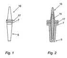
- FIG. 1is a side view of a body implantable device
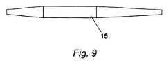
- FIG. 2is a front sectional view through the device of FIG. 1 ;
- FIG. 3is a side view of a first component of the FIG. 1 device
- FIG. 4is a front sectional view through the FIG. 3 component
- FIG. 5is a front view of a second component of the FIG. 1 device
- FIG. 6is a side sectional view through the FIG. 5 component
- FIG. 7is a side view of a bearing plate used in the FIG. 1 device
- FIG. 8is a plan view of the bearing plate
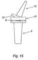
- FIG. 9is a side view of a flexible component of the FIG. 1 device.
- FIG. 10is a perspective view of the FIG. 1 device
- FIG. 11is a perspective view of the FIG. 1 device in flexion/extension
- FIG. 12is a side view of the FIG. 1 device in flexion/extension
- FIG. 13is a perspective view of the FIG. 1 device showing lateral deviation
- FIG. 14is a side view of the FIG. 1 device showing lateral deviation
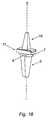
- FIG. 15is a front view of the FIG. 1 device showing lateral deviation
- FIG. 16is a perspective view of the FIG. 1 device showing relative rotation of the two components
- FIG. 17is a side view of the FIG. 1 device showing relative rotation of the two components
- FIG. 18is a front sectional view of an alternative embodiment of the invention.
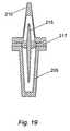
- FIG. 19is a front sectional view of a further alternative embodiment of the invention.
- FIG. 20is a front section view of a yet further alternative embodiment of the invention.
- a body implantable device designed for use as the replacement wrist jointcomprises a first component 5 and a second component 10 .
- the first component 5is dimensioned and adapted to be implanted within the distal end of the intramedullary canal of the radius
- the second component 10is intended and adapted to be implanted into a bore created in the proximal part of the carpus and/or metacarpals.
- Each of the first and second components 5 , 10can have external protrusions such as ridges or screw-threads (not shown) to enhance retention of the component within the bone portion into which it is implanted.
- each of the first and second components 5 , 10is sized and adapted to fit within either the intramedullary canal of the radius or the bore created in the carpus and/or metacarpals and to form an interference fit within that cavity, so that they can be retained therein merely by friction between the outer surface of the components 5 , 10 , and the inner surface of the cavity in the bone(s).
- the first component 5comprises a tapered stem 6 adapted to fit within the distal intramedullary canal of the radius, and a head 7 located on top of the stem 6 .
- the head 7has laterally extending arms and has a distal convex bearing surface 8 that is curved from the front of the first component 5 to the back.
- the radius of curvature of the surface 8is approximately 16 mm.
- the first component 5has a blind-ended bore 9 extending axially through the stem 6 , and presenting an aperture through the upper surface 8 of the head 7 .
- the first and second componentsare made from ultrahigh molecular weight polyethylene.
- the second component 10also has a tapered stem 11 , and a head 12 , again with laterally extending arms, and a proximal bearing surface 13 .
- the proximal bearing surface 13 of the head 12is also convex, but is curved from one side of the second component 10 to the other side.
- the radius of curvature of the bearing face 13is approximately 65 mm.
- the second component 10has a blind-ended bore 14 extending axially through the stem 11 , and presenting an aperture through the upper surface 13 of the head 12 .
- a flexible rod 15 of silicone as shown in FIG. 9has a central cylindrical portion and tapered ends that are adapted to be received within the blind ended bores 9 , 14 of the first and second components 5 , 10 respectively.
- the length of the flexible rodis typically slightly less than the combined lengths of the blind ended bores 9 , 14 , so that when the device is assembled with the first and second components 5 , 10 placed head-to-head, with the bores 9 , 14 aligned and the arms on the respective heads arranged parallel to one another, the flexible rod 15 can move axially within the cavity formed by the two bores 9 , 14 .
- a bearing plate 17 formed of stainless steelis typically provided between the bearing surfaces 8 , 13 of the heads 7 , 12 , and typically has an aperture 18 to allow passage of the flexible rod 15 through the bearing plate 17 .
- the aperture 18is aligned with the bores 9 , 14 when the device is assembled.
- the deviceis made up such that the bearing surface 8 of the first component 5 articulates against one surface 17 a of the bearing plate 17 , while the bearing surface 13 of the second component 10 articulates against the opposite surface 17 b of the bearing plate 17 .
- the bearing plate 17typically has arms extending from the surface 17 b plate to engage the side walls of the head 12 of the second portion 10 . It will be appreciated that embodiments of the invention can function satisfactorily without a bearing plate 17 , and that bearing plates can be used without side walls.
- FIGS. 10 to 17the device is shown at rest in FIG. 10 , with the two components 5 , 10 in axial alignment with one another with the bearing plate 17 interposed.
- the flexible rod 15is not bent or energised in any way and is held within the cavity formed by the bores 9 , 14 .
- FIGS. 11 and 12show the device in flexion, with the second component 10 pivoting with respect to the first component 5 around the y-axis shown in FIG. 10 . Notice that the bearing plate 17 moves with the second portion 10 relative to the first portion 5 , and that the bearing surface 8 of the head 7 of the first portion 5 articulates against the face 17 a of the bearing plate 17 .
- the front to back curvature of the bearing surface 8promotes a smooth articulation about the y-axis.
- the ends of the flexible rod 15remain within the bores 9 , 14 , and the central portion of the rod 15 bends to accommodate and control the flexion. Since the rod 15 can move axially within the cavity formed by the bores 9 , 14 , the pivot axis formed in the central portion of the rod 15 can move axially with respect to the first and second portions 5 , 10 as the device flexes, thereby allowing a greater range of movement of the joint. Also, since the flexible rod 15 can move within the cavity formed by the bores 9 , 14 , the two portions 5 , 10 can extend relative to one another along the x-axis, while undergoing flexion, extension, medial/lateral deviation and/or rotation.
- FIGS. 13 , 14 and 15show the joint moving in medial/lateral deviation around the z-axis of FIG. 10 , i.e. as if moving in radio-ulnar deviation when in place in the body.
- the bearing plate 17remains with the first portion 5 , and the bearing surface 13 of the head 12 of the second portion 10 articulates against the surface 17 b of the plate 17 .
- the pivotal movement of the plate 17 relative to the first portion 5is negligible, and the lateral movement of the first portion 10 is constrained by the head 12 moving within the confines of the arms of the bearing plate 17 .
- the plate 17can move relative to the first portion 5 , for example, when the flexible rod 15 moves axially to allow the extension of the device.
- FIGS. 16 and 17show relative rotational movement of the two portions 5 , 10 around the x-axis. Notice that the arms of the bearing plate 17 keep the plate 17 stationary with respect to the second portion 10 , and the two portions pivot around the axis of the flexible rod 15 held straight within the central cavity formed by the bores 9 , 14 .
- the jointto carry out more complex combination movements involving a combination of rotation, medial/lateral deviation, and extension/flexion, in any combination. It is also possible for axial separation of the two portions to occur during any such movement.
- FIG. 18shows an alternative embodiment, having a first component 105 , a second component 110 , a flexible member 115 and a bearing plate 117 .
- each of the first and second components 105 , 110 and bearing plate 117have a respective internal bore though which flexible member 115 extends. Both ends of the bore of flexible member 115 are chamfered, as are the mouths of the bores of the first and second components 105 , 110 ; this is advantageous, as it means there are no sharp edges which could abrade and damage the flexible member 115 .
- the cavity formed by the bores in the first and second components 105 , 110is longer and wider than flexible member 115 , providing clearance between flexible member 115 and the cavity in both axial and lateral directions.
- flexible member 115is not fixed to either of the first or second components 105 , 110 , flexible member 115 can move both axially, laterally and rotationally within the cavity; the flexible member thus has three degrees of freedom of movement.
- FIG. 19shows a further embodiment of the invention which is very similar to the FIG. 18 embodiment and like components have similar reference numbers, which are prefixed by “2”.
- the bores in the first and second components 205 , 210increase in width towards the respective bore mouths at a greater rate than the increase in diameter of the flexible member 215 due to its taper. This provides a greater clearance between flexible member 115 and the bores at the bore mouths compared to the bore ends.
- the FIG. 19 embodimenthas the advantage that stresses on the flexible member 215 are further reduced due to the relatively large clearance at the mouths of the bores in a first and second components 205 , 210 and a correspondingly wide bore in flexible member 215 .
- FIG. 18 and FIG. 19 embodimentsare not necessarily drawn to scale.
- FIG. 20shows a further embodiment of the invention, which is similar to the FIGS. 18 and 19 embodiments; like parts have similar reference numerals, prefixed with “3”.
- the lateral clearance between flexible member 115 and the cavity formed by the bores in the first and second components 305 , 310is relatively small at the inner ends of each bore (i.e. flexible member 115 is a close lateral fit within the cavity at each end), but towards the bore mouths the diameter of each bore increases at a greater rate than the diameter of flexible member 315 to leave a wider lateral clearance with flexible member 115 at the bore mouths.
- the rate of change in width of each boreincreases towards the bore mouth, so that the bore mouth is flared like the bell of a trumpet.
- the flare at the bore mouthcan be even more pronounced than shown in FIG. 20 , with the flaring of the bore starting even further from the bore mouth.
- the flaring of each boreis smooth, so that the bore mouth does not have any sharp corners which could otherwise abrade and damage flexible member 315 .
- the bore in bearing plate 317is also chamfered so that there are no sharp corners here either.
- FIG. 20 embodimentprovides the advantage that the close fit between flexible member 315 at the bore ends prevents the first and second components 305 , 310 from dislocating from each other, whilst the wider fit at the bore mouths helps prevent excessive wear on flexible member 315 .
Landscapes
- Health & Medical Sciences (AREA)
- Orthopedic Medicine & Surgery (AREA)
- Cardiology (AREA)
- Oral & Maxillofacial Surgery (AREA)
- Transplantation (AREA)
- Engineering & Computer Science (AREA)
- Biomedical Technology (AREA)
- Heart & Thoracic Surgery (AREA)
- Vascular Medicine (AREA)
- Life Sciences & Earth Sciences (AREA)
- Animal Behavior & Ethology (AREA)
- General Health & Medical Sciences (AREA)
- Public Health (AREA)
- Veterinary Medicine (AREA)
- Prostheses (AREA)
Abstract
Description
Claims (26)
Applications Claiming Priority (3)
| Application Number | Priority Date | Filing Date | Title |
|---|---|---|---|
| GBGB0219758.0AGB0219758D0 (en) | 2002-08-24 | 2002-08-24 | Device |
| GB0219758.0 | 2002-08-24 | ||
| PCT/GB2003/003763WO2004017861A2 (en) | 2002-08-24 | 2003-08-26 | Implantable replacement joint |
Publications (2)
| Publication Number | Publication Date |
|---|---|
| US20060167559A1 US20060167559A1 (en) | 2006-07-27 |
| US7842091B2true US7842091B2 (en) | 2010-11-30 |
Family
ID=9942924
Family Applications (1)
| Application Number | Title | Priority Date | Filing Date |
|---|---|---|---|
| US10/525,446Expired - Fee RelatedUS7842091B2 (en) | 2002-08-24 | 2003-08-26 | Implantable replacement joint |
Country Status (5)
| Country | Link |
|---|---|
| US (1) | US7842091B2 (en) |
| EP (1) | EP1531759B1 (en) |
| AU (1) | AU2003260760A1 (en) |
| GB (1) | GB0219758D0 (en) |
| WO (1) | WO2004017861A2 (en) |
Cited By (17)
| Publication number | Priority date | Publication date | Assignee | Title |
|---|---|---|---|---|
| US20120150309A1 (en)* | 2009-04-29 | 2012-06-14 | Roelof Marissen | Hinge structure |
| US20120158153A1 (en)* | 2009-06-23 | 2012-06-21 | Replication Medical Inc. | Trapezium prosthesis |
| US8394097B2 (en) | 2007-03-20 | 2013-03-12 | Memometal Technologies | Osteosynthesis device |
| US8414583B2 (en) | 2008-09-09 | 2013-04-09 | Memometal Technologies | Resorptive intramedullary implant between two bones or two bone fragments |
| US8475456B2 (en) | 2005-04-14 | 2013-07-02 | Memometal Technologies | Intramedullar osteosynthetic device of two bone parts, in particular of the hand and/or foot |
| US20130297020A1 (en)* | 2007-11-02 | 2013-11-07 | Biomet Uk Limited | Prosthesis For Stimulating Natural Kinematics |
| US9474561B2 (en) | 2013-11-19 | 2016-10-25 | Wright Medical Technology, Inc. | Two-wire technique for installing hammertoe implant |
| US9498273B2 (en) | 2010-06-02 | 2016-11-22 | Wright Medical Technology, Inc. | Orthopedic implant kit |
| US9498266B2 (en) | 2014-02-12 | 2016-11-22 | Wright Medical Technology, Inc. | Intramedullary implant, system, and method for inserting an implant into a bone |
| US9504582B2 (en) | 2012-12-31 | 2016-11-29 | Wright Medical Technology, Inc. | Ball and socket implants for correction of hammer toes and claw toes |
| US9545274B2 (en) | 2014-02-12 | 2017-01-17 | Wright Medical Technology, Inc. | Intramedullary implant, system, and method for inserting an implant into a bone |
| US9603643B2 (en) | 2010-06-02 | 2017-03-28 | Wright Medical Technology, Inc. | Hammer toe implant with expansion portion for retrograde approach |
| US9724139B2 (en) | 2013-10-01 | 2017-08-08 | Wright Medical Technology, Inc. | Hammer toe implant and method |
| US9757168B2 (en) | 2015-03-03 | 2017-09-12 | Howmedica Osteonics Corp. | Orthopedic implant and methods of implanting and removing same |
| US9808296B2 (en) | 2014-09-18 | 2017-11-07 | Wright Medical Technology, Inc. | Hammertoe implant and instrument |
| US10470807B2 (en) | 2016-06-03 | 2019-11-12 | Stryker European Holdings I, Llc | Intramedullary implant and method of use |
| US10682237B2 (en)* | 2015-09-03 | 2020-06-16 | Cmc Sert Ltd. | Prosthesis for replacing joint in a human hand or foot |
Families Citing this family (17)
| Publication number | Priority date | Publication date | Assignee | Title |
|---|---|---|---|---|
| US6338790B1 (en) | 1998-10-08 | 2002-01-15 | Therasense, Inc. | Small volume in vitro analyte sensor with diffusible or non-leachable redox mediator |
| US20020120340A1 (en) | 2001-02-23 | 2002-08-29 | Metzger Robert G. | Knee joint prosthesis |
| US7497874B1 (en) | 2001-02-23 | 2009-03-03 | Biomet Manufacturing Corp. | Knee joint prosthesis |
| US7383164B2 (en)* | 2004-03-05 | 2008-06-03 | Depuy Products, Inc. | System and method for designing a physiometric implant system |
| JP5448842B2 (en) | 2007-01-10 | 2014-03-19 | バイオメト マニファクチャリング コーポレイション | Knee joint prosthesis system and implantation method |
| US8187280B2 (en) | 2007-10-10 | 2012-05-29 | Biomet Manufacturing Corp. | Knee joint prosthesis system and method for implantation |
| US8562616B2 (en) | 2007-10-10 | 2013-10-22 | Biomet Manufacturing, Llc | Knee joint prosthesis system and method for implantation |
| US8163028B2 (en) | 2007-01-10 | 2012-04-24 | Biomet Manufacturing Corp. | Knee joint prosthesis system and method for implantation |
| US8328873B2 (en) | 2007-01-10 | 2012-12-11 | Biomet Manufacturing Corp. | Knee joint prosthesis system and method for implantation |
| US10022154B2 (en) | 2007-05-01 | 2018-07-17 | Moximed, Inc. | Femoral and tibial base components |
| US20080275567A1 (en)* | 2007-05-01 | 2008-11-06 | Exploramed Nc4, Inc. | Extra-Articular Implantable Mechanical Energy Absorbing Systems |
| US8052755B2 (en)* | 2008-05-09 | 2011-11-08 | Remi Sciences, Inc. | Ulnar head prosthesis system |
| US7875082B2 (en)* | 2008-05-09 | 2011-01-25 | Remi Sciences, Inc. | Ulnar head prosthesis system |
| US8668743B2 (en) | 2010-11-02 | 2014-03-11 | Adam D. Perler | Prosthetic device with multi-axis dual bearing assembly and methods for resection |
| EP2804565B1 (en)* | 2011-12-22 | 2018-03-07 | Arthrosurface Incorporated | System for bone fixation |
| US8764842B2 (en)* | 2012-05-31 | 2014-07-01 | Michael Graham | Interphalangeal joint implant methods and apparatus |
| DE102019005770A1 (en)* | 2019-08-16 | 2021-02-18 | Alfons Erdmann | Surgical kit to supplement a joint |
Citations (20)
| Publication number | Priority date | Publication date | Assignee | Title |
|---|---|---|---|---|
| US3462765A (en) | 1967-01-06 | 1969-08-26 | Dow Corning | Surgically implantable prosthetic joint |
| US3990116A (en)* | 1974-10-17 | 1976-11-09 | Fixel Irving E | Pretensioned prosthetic device for skeletal joints |
| US4304011A (en) | 1980-08-25 | 1981-12-08 | Whelan Iii Edward J | Semi-constrained metacarpophalangeal prosthesis |
| US4307473A (en) | 1980-02-11 | 1981-12-29 | Weber Edward R | Prosthetic wrist joint |
| EP0057597A2 (en) | 1981-01-30 | 1982-08-11 | Oec Europe Limited | A joint prosthesis |
| US4462120A (en) | 1981-07-06 | 1984-07-31 | Andre Rambert | Total knee prosthesis |
| EP0115564A1 (en) | 1982-12-16 | 1984-08-15 | GebràDer Sulzer Aktiengesellschaft | Single-piece metallic socket for the anchoring shaft of a small joint prothesis |
| WO1984004668A1 (en) | 1983-05-24 | 1984-12-06 | American Hospital Supply Corp | Protective device for implantable prosthesis |
| GB2160779A (en) | 1982-09-06 | 1986-01-02 | Oec Europ Ltd | A joint prosthesis |
| GB2169512A (en) | 1985-01-10 | 1986-07-16 | Trade & Industry The Secretary | Joint prosthesis |
| US5011497A (en)* | 1987-10-29 | 1991-04-30 | Atos Medical Ab | Joint prosthesis |
| WO1991016014A1 (en) | 1990-04-23 | 1991-10-31 | Medevelop Ab | Artificial joint mechanism |
| US5062851A (en) | 1989-04-25 | 1991-11-05 | Medevelop Ab | Anchoring element for supporting a joint mechanism of a finger or other reconstructed joint |
| EP0524874A1 (en) | 1991-07-24 | 1993-01-27 | Hades | Joint prosthesis, especially trapezoid-metacarpal and digital joint |
| WO1994013228A1 (en) | 1992-12-15 | 1994-06-23 | International Polymer Engineering, Inc. | Joint implant |
| FR2724309A1 (en) | 1994-09-14 | 1996-03-15 | Procerati | Bone joint prosthesis anchoring element |
| US5534033A (en) | 1995-06-05 | 1996-07-09 | Carbomedics, Inc. | Orthopedic prosthetic implants with pyrolytic carbon or ceramic articulating surfaces |
| US5683466A (en)* | 1996-03-26 | 1997-11-04 | Vitale; Glenn C. | Joint surface replacement system |
| US5702472A (en)* | 1996-12-26 | 1997-12-30 | Huebner; Randall J. | Phalangeal finger joint prosthesis and method |
| EP0925765A2 (en) | 1997-12-12 | 1999-06-30 | Bristol-Myers Squibb Company | Mobile bearing knee with metal on metal interface |
- 2002
- 2002-08-24GBGBGB0219758.0Apatent/GB0219758D0/ennot_activeCeased
- 2003
- 2003-08-26EPEP03792530.2Apatent/EP1531759B1/ennot_activeExpired - Lifetime
- 2003-08-26AUAU2003260760Apatent/AU2003260760A1/ennot_activeAbandoned
- 2003-08-26USUS10/525,446patent/US7842091B2/ennot_activeExpired - Fee Related
- 2003-08-26WOPCT/GB2003/003763patent/WO2004017861A2/ennot_activeApplication Discontinuation
Patent Citations (20)
| Publication number | Priority date | Publication date | Assignee | Title |
|---|---|---|---|---|
| US3462765A (en) | 1967-01-06 | 1969-08-26 | Dow Corning | Surgically implantable prosthetic joint |
| US3990116A (en)* | 1974-10-17 | 1976-11-09 | Fixel Irving E | Pretensioned prosthetic device for skeletal joints |
| US4307473A (en) | 1980-02-11 | 1981-12-29 | Weber Edward R | Prosthetic wrist joint |
| US4304011A (en) | 1980-08-25 | 1981-12-08 | Whelan Iii Edward J | Semi-constrained metacarpophalangeal prosthesis |
| EP0057597A2 (en) | 1981-01-30 | 1982-08-11 | Oec Europe Limited | A joint prosthesis |
| US4462120A (en) | 1981-07-06 | 1984-07-31 | Andre Rambert | Total knee prosthesis |
| GB2160779A (en) | 1982-09-06 | 1986-01-02 | Oec Europ Ltd | A joint prosthesis |
| EP0115564A1 (en) | 1982-12-16 | 1984-08-15 | GebràDer Sulzer Aktiengesellschaft | Single-piece metallic socket for the anchoring shaft of a small joint prothesis |
| WO1984004668A1 (en) | 1983-05-24 | 1984-12-06 | American Hospital Supply Corp | Protective device for implantable prosthesis |
| GB2169512A (en) | 1985-01-10 | 1986-07-16 | Trade & Industry The Secretary | Joint prosthesis |
| US5011497A (en)* | 1987-10-29 | 1991-04-30 | Atos Medical Ab | Joint prosthesis |
| US5062851A (en) | 1989-04-25 | 1991-11-05 | Medevelop Ab | Anchoring element for supporting a joint mechanism of a finger or other reconstructed joint |
| WO1991016014A1 (en) | 1990-04-23 | 1991-10-31 | Medevelop Ab | Artificial joint mechanism |
| EP0524874A1 (en) | 1991-07-24 | 1993-01-27 | Hades | Joint prosthesis, especially trapezoid-metacarpal and digital joint |
| WO1994013228A1 (en) | 1992-12-15 | 1994-06-23 | International Polymer Engineering, Inc. | Joint implant |
| FR2724309A1 (en) | 1994-09-14 | 1996-03-15 | Procerati | Bone joint prosthesis anchoring element |
| US5534033A (en) | 1995-06-05 | 1996-07-09 | Carbomedics, Inc. | Orthopedic prosthetic implants with pyrolytic carbon or ceramic articulating surfaces |
| US5683466A (en)* | 1996-03-26 | 1997-11-04 | Vitale; Glenn C. | Joint surface replacement system |
| US5702472A (en)* | 1996-12-26 | 1997-12-30 | Huebner; Randall J. | Phalangeal finger joint prosthesis and method |
| EP0925765A2 (en) | 1997-12-12 | 1999-06-30 | Bristol-Myers Squibb Company | Mobile bearing knee with metal on metal interface |
Non-Patent Citations (1)
| Title |
|---|
| Beevers, D.J., et al.: "Metacarpophalengeal Joint Prostheses: A Review of Past and Current Designs." Proceedings of the Institution of Mechanical Engineers. Journal of Engineering in Medicine. Part H, Mechanical Engineering Publications Ltd., London, Great Britain. |
Cited By (43)
| Publication number | Priority date | Publication date | Assignee | Title |
|---|---|---|---|---|
| US10022167B2 (en) | 2005-04-14 | 2018-07-17 | Stryker European Holdings I, Llc | Method of osteosyntheses or arthrodesis of two-bone parts, in particular of the hand and / or foot |
| US11478285B2 (en) | 2005-04-14 | 2022-10-25 | Stryker European Operations Holdings Llc | Device for osteosyntheses or arthrodesis of two-bone parts, in particular of the hand and/or foot |
| US11006984B2 (en) | 2005-04-14 | 2021-05-18 | Stryker European Operations Holdings Llc | Device for osteosyntheses or arthrodesis of two-bone parts, in particular of the hand and / or foot |
| US8475456B2 (en) | 2005-04-14 | 2013-07-02 | Memometal Technologies | Intramedullar osteosynthetic device of two bone parts, in particular of the hand and/or foot |
| US9283007B2 (en) | 2005-04-14 | 2016-03-15 | Stryker European Holdings I, Llc | Device for osteosyntheses or arthrodeses of two- bone parts, in particular of the hand and / or foot |
| US9492215B2 (en) | 2005-04-14 | 2016-11-15 | Stryker European Holdings I, Llc | Method of osteosyntheses or arthrodeses of two- bone parts, in particular of the hand and / or foot |
| US8394097B2 (en) | 2007-03-20 | 2013-03-12 | Memometal Technologies | Osteosynthesis device |
| US9161789B2 (en) | 2007-03-20 | 2015-10-20 | Memometal Technologies | Osteosynthesis device |
| US9839453B2 (en) | 2007-03-20 | 2017-12-12 | Stryker European Holdings I, Llc | Osteosynthesis device |
| US10912594B2 (en) | 2007-03-20 | 2021-02-09 | Stryker European Holdings I, Llc | Osteosynthesis device |
| US12396766B2 (en) | 2007-03-20 | 2025-08-26 | Stryker European Operations Holdings Llc | Osteosynthesis device |
| US20130297020A1 (en)* | 2007-11-02 | 2013-11-07 | Biomet Uk Limited | Prosthesis For Stimulating Natural Kinematics |
| US9381079B2 (en)* | 2007-11-02 | 2016-07-05 | Biomet Uk Limited | Prosthesis for stimulating natural kinematics |
| US9168074B2 (en) | 2008-09-09 | 2015-10-27 | Memometal Technologies | Resorptive intramedullary implant between two bones or two bone fragments |
| US12059186B2 (en) | 2008-09-09 | 2024-08-13 | Stryker European Operations Holdings Llc | Resorptive intramedullary implant between two bones or two bone fragments |
| US12383319B2 (en) | 2008-09-09 | 2025-08-12 | Stryker European Operations Holdings Llc | Resorptive intramedullary implant between two bones or two bone fragments |
| US12390255B2 (en) | 2008-09-09 | 2025-08-19 | Stryker European Operations Holdings Llc | Resorptive intramedullary implant between two bones or two bone fragments |
| US8414583B2 (en) | 2008-09-09 | 2013-04-09 | Memometal Technologies | Resorptive intramedullary implant between two bones or two bone fragments |
| US10383671B2 (en) | 2008-09-09 | 2019-08-20 | Stryker European Holdings I, Llc | Resorptive intramedullary implant between two bones or two bone fragments |
| US20120150309A1 (en)* | 2009-04-29 | 2012-06-14 | Roelof Marissen | Hinge structure |
| US20120158153A1 (en)* | 2009-06-23 | 2012-06-21 | Replication Medical Inc. | Trapezium prosthesis |
| US10736676B2 (en) | 2010-06-02 | 2020-08-11 | Wright Medical Technology, Inc. | Orthopedic implant kit |
| US9603643B2 (en) | 2010-06-02 | 2017-03-28 | Wright Medical Technology, Inc. | Hammer toe implant with expansion portion for retrograde approach |
| US9498273B2 (en) | 2010-06-02 | 2016-11-22 | Wright Medical Technology, Inc. | Orthopedic implant kit |
| US9877753B2 (en) | 2010-06-02 | 2018-01-30 | Wright Medical Technology, Inc. | Orthopedic implant kit |
| US9949775B2 (en) | 2010-06-02 | 2018-04-24 | Wright Medical Technology, Inc. | Hammer toe implant with expansion portion for retrograde approach |
| US10278828B2 (en) | 2012-12-31 | 2019-05-07 | Wright Medical Technology, Inc. | Ball and socket implants for correction of hammer toes and claw toes |
| US9504582B2 (en) | 2012-12-31 | 2016-11-29 | Wright Medical Technology, Inc. | Ball and socket implants for correction of hammer toes and claw toes |
| US9724139B2 (en) | 2013-10-01 | 2017-08-08 | Wright Medical Technology, Inc. | Hammer toe implant and method |
| US9675392B2 (en) | 2013-11-19 | 2017-06-13 | Wright Medical Technology, Inc. | Two-wire technique for installing hammertoe implant |
| US9474561B2 (en) | 2013-11-19 | 2016-10-25 | Wright Medical Technology, Inc. | Two-wire technique for installing hammertoe implant |
| US9545274B2 (en) | 2014-02-12 | 2017-01-17 | Wright Medical Technology, Inc. | Intramedullary implant, system, and method for inserting an implant into a bone |
| US9498266B2 (en) | 2014-02-12 | 2016-11-22 | Wright Medical Technology, Inc. | Intramedullary implant, system, and method for inserting an implant into a bone |
| US9808296B2 (en) | 2014-09-18 | 2017-11-07 | Wright Medical Technology, Inc. | Hammertoe implant and instrument |
| US10299840B2 (en) | 2014-09-18 | 2019-05-28 | Wright Medical Technology, Inc. | Hammertoe implant and instrument |
| US10702318B2 (en) | 2015-03-03 | 2020-07-07 | Howmedica Osteonics Corp. | Orthopedic implant and methods of implanting and removing same |
| US11672576B2 (en) | 2015-03-03 | 2023-06-13 | Howmedica Osteonics Corp. | Orthopedic implant and methods of implanting and removing same |
| US12383318B2 (en) | 2015-03-03 | 2025-08-12 | Howmedica Osteonics Corp. | Orthopedic implant and methods of implanting and removing same |
| US9757168B2 (en) | 2015-03-03 | 2017-09-12 | Howmedica Osteonics Corp. | Orthopedic implant and methods of implanting and removing same |
| US10682237B2 (en)* | 2015-09-03 | 2020-06-16 | Cmc Sert Ltd. | Prosthesis for replacing joint in a human hand or foot |
| US11272966B2 (en) | 2016-06-03 | 2022-03-15 | Stryker European Operations Holdings Llc | Intramedullary implant and method of use |
| US11992248B2 (en) | 2016-06-03 | 2024-05-28 | Stryker European Operations Holdings Llc | Intramedullary implant and method of use |
| US10470807B2 (en) | 2016-06-03 | 2019-11-12 | Stryker European Holdings I, Llc | Intramedullary implant and method of use |
Also Published As
| Publication number | Publication date |
|---|---|
| GB0219758D0 (en) | 2002-10-02 |
| WO2004017861A3 (en) | 2004-10-21 |
| WO2004017861A2 (en) | 2004-03-04 |
| AU2003260760A8 (en) | 2004-03-11 |
| EP1531759A2 (en) | 2005-05-25 |
| US20060167559A1 (en) | 2006-07-27 |
| EP1531759B1 (en) | 2013-06-19 |
| AU2003260760A1 (en) | 2004-03-11 |
Similar Documents
| Publication | Publication Date | Title |
|---|---|---|
| US7842091B2 (en) | Implantable replacement joint | |
| US5702472A (en) | Phalangeal finger joint prosthesis and method | |
| US6689169B2 (en) | Prothesis | |
| EP1550420B1 (en) | Joint prosthesis with adjustable head | |
| US4784661A (en) | Total wrist prosthesis | |
| US5405401A (en) | Prosthesis for replacement of joints between long bones in the hand | |
| US9681954B2 (en) | Joint prosthesis system with positionable head | |
| US4307473A (en) | Prosthetic wrist joint | |
| AU2020247288B2 (en) | Bone joint implants | |
| US20080288079A1 (en) | Radial Head Implant and Related Instrument | |
| JP2003319956A (en) | Wrist prosthesis | |
| JPH06508276A (en) | finger joint prosthesis | |
| NZ517859A (en) | Joint prosthesis | |
| Beevers et al. | Metacarpophalangeal joint prostheses: a review of past and current designs | |
| US20200405496A1 (en) | Bone joint implants | |
| US9132019B2 (en) | Metacarpal-phalangeal prosthesis | |
| JP3035696B2 (en) | Artificial knuckle | |
| JP3164675B2 (en) | Joint component |
Legal Events
| Date | Code | Title | Description |
|---|---|---|---|
| AS | Assignment | Owner name:GRAMPIAN HEALTH BOARD, UNITED KINGDOM Free format text:ASSIGNMENT OF ASSIGNORS INTEREST;ASSIGNOR:GRAMPIAN UNIVERSITY HOSPITALS HEALTH SERVICE TRUST;REEL/FRAME:018078/0307 Effective date:20040325 Owner name:GRAMPIAN UNIVERSITY HOSPITALS NHS TRUST, UNITED KI Free format text:ASSIGNMENT OF ASSIGNORS INTEREST;ASSIGNORS:JOHNSTONE, ALAN JOHN;SHEPHERD, DUNCAN EOIN THOMSON;REEL/FRAME:018079/0963 Effective date:20031105 Owner name:ABERDEEN, UNIVERSITY OF, UNITED KINGDOM Free format text:ASSIGNMENT OF ASSIGNORS INTEREST;ASSIGNORS:JOHNSTONE, ALAN JOHN;SHEPHERD, DUNCAN EOIN THOMSON;REEL/FRAME:018079/0963 Effective date:20031105 | |
| FPAY | Fee payment | Year of fee payment:4 | |
| FEPP | Fee payment procedure | Free format text:MAINTENANCE FEE REMINDER MAILED (ORIGINAL EVENT CODE: REM.) | |
| LAPS | Lapse for failure to pay maintenance fees | Free format text:PATENT EXPIRED FOR FAILURE TO PAY MAINTENANCE FEES (ORIGINAL EVENT CODE: EXP.); ENTITY STATUS OF PATENT OWNER: SMALL ENTITY | |
| STCH | Information on status: patent discontinuation | Free format text:PATENT EXPIRED DUE TO NONPAYMENT OF MAINTENANCE FEES UNDER 37 CFR 1.362 | |
| FP | Lapsed due to failure to pay maintenance fee | Effective date:20181130 |