US7842032B2 - Apparatus and methods for the selective removal of tissue - Google Patents
Apparatus and methods for the selective removal of tissueDownload PDFInfo
- Publication number
- US7842032B2 US7842032B2US11/737,112US73711207AUS7842032B2US 7842032 B2US7842032 B2US 7842032B2US 73711207 AUS73711207 AUS 73711207AUS 7842032 B2US7842032 B2US 7842032B2
- Authority
- US
- United States
- Prior art keywords
- ultrasonic
- distal end
- tissue
- chamber
- ultrasonic tip
- Prior art date
- Legal status (The legal status is an assumption and is not a legal conclusion. Google has not performed a legal analysis and makes no representation as to the accuracy of the status listed.)
- Active - Reinstated, expires
Links
Images


Classifications
- A—HUMAN NECESSITIES
- A61—MEDICAL OR VETERINARY SCIENCE; HYGIENE
- A61B—DIAGNOSIS; SURGERY; IDENTIFICATION
- A61B17/00—Surgical instruments, devices or methods
- A61B17/22—Implements for squeezing-off ulcers or the like on inner organs of the body; Implements for scraping-out cavities of body organs, e.g. bones; for invasive removal or destruction of calculus using mechanical vibrations; for removing obstructions in blood vessels, not otherwise provided for
- A61B17/22004—Implements for squeezing-off ulcers or the like on inner organs of the body; Implements for scraping-out cavities of body organs, e.g. bones; for invasive removal or destruction of calculus using mechanical vibrations; for removing obstructions in blood vessels, not otherwise provided for using mechanical vibrations, e.g. ultrasonic shock waves
- A—HUMAN NECESSITIES
- A61—MEDICAL OR VETERINARY SCIENCE; HYGIENE
- A61B—DIAGNOSIS; SURGERY; IDENTIFICATION
- A61B18/00—Surgical instruments, devices or methods for transferring non-mechanical forms of energy to or from the body
- A61B18/02—Surgical instruments, devices or methods for transferring non-mechanical forms of energy to or from the body by cooling, e.g. cryogenic techniques
- A61B18/0206—Surgical instruments, devices or methods for transferring non-mechanical forms of energy to or from the body by cooling, e.g. cryogenic techniques ultrasonic, e.g. for destroying tissue or enhancing freezing
- A—HUMAN NECESSITIES
- A61—MEDICAL OR VETERINARY SCIENCE; HYGIENE
- A61F—FILTERS IMPLANTABLE INTO BLOOD VESSELS; PROSTHESES; DEVICES PROVIDING PATENCY TO, OR PREVENTING COLLAPSING OF, TUBULAR STRUCTURES OF THE BODY, e.g. STENTS; ORTHOPAEDIC, NURSING OR CONTRACEPTIVE DEVICES; FOMENTATION; TREATMENT OR PROTECTION OF EYES OR EARS; BANDAGES, DRESSINGS OR ABSORBENT PADS; FIRST-AID KITS
- A61F7/00—Heating or cooling appliances for medical or therapeutic treatment of the human body
- A61F7/12—Devices for heating or cooling internal body cavities
- A—HUMAN NECESSITIES
- A61—MEDICAL OR VETERINARY SCIENCE; HYGIENE
- A61M—DEVICES FOR INTRODUCING MEDIA INTO, OR ONTO, THE BODY; DEVICES FOR TRANSDUCING BODY MEDIA OR FOR TAKING MEDIA FROM THE BODY; DEVICES FOR PRODUCING OR ENDING SLEEP OR STUPOR
- A61M11/00—Sprayers or atomisers specially adapted for therapeutic purposes
- A—HUMAN NECESSITIES
- A61—MEDICAL OR VETERINARY SCIENCE; HYGIENE
- A61N—ELECTROTHERAPY; MAGNETOTHERAPY; RADIATION THERAPY; ULTRASOUND THERAPY
- A61N7/00—Ultrasound therapy
- A—HUMAN NECESSITIES
- A61—MEDICAL OR VETERINARY SCIENCE; HYGIENE
- A61B—DIAGNOSIS; SURGERY; IDENTIFICATION
- A61B18/00—Surgical instruments, devices or methods for transferring non-mechanical forms of energy to or from the body
- A61B18/02—Surgical instruments, devices or methods for transferring non-mechanical forms of energy to or from the body by cooling, e.g. cryogenic techniques
- A61B18/0218—Surgical instruments, devices or methods for transferring non-mechanical forms of energy to or from the body by cooling, e.g. cryogenic techniques with open-end cryogenic probe, e.g. for spraying fluid directly on tissue or via a tissue-contacting porous tip
- A—HUMAN NECESSITIES
- A61—MEDICAL OR VETERINARY SCIENCE; HYGIENE
- A61B—DIAGNOSIS; SURGERY; IDENTIFICATION
- A61B17/00—Surgical instruments, devices or methods
- A61B17/32—Surgical cutting instruments
- A61B17/320068—Surgical cutting instruments using mechanical vibrations, e.g. ultrasonic
- A61B2017/320069—Surgical cutting instruments using mechanical vibrations, e.g. ultrasonic for ablating tissue
- A—HUMAN NECESSITIES
- A61—MEDICAL OR VETERINARY SCIENCE; HYGIENE
- A61B—DIAGNOSIS; SURGERY; IDENTIFICATION
- A61B17/00—Surgical instruments, devices or methods
- A61B17/32—Surgical cutting instruments
- A61B17/320068—Surgical cutting instruments using mechanical vibrations, e.g. ultrasonic
- A61B2017/320089—Surgical cutting instruments using mechanical vibrations, e.g. ultrasonic node location
- A—HUMAN NECESSITIES
- A61—MEDICAL OR VETERINARY SCIENCE; HYGIENE
- A61B—DIAGNOSIS; SURGERY; IDENTIFICATION
- A61B18/00—Surgical instruments, devices or methods for transferring non-mechanical forms of energy to or from the body
- A61B18/02—Surgical instruments, devices or methods for transferring non-mechanical forms of energy to or from the body by cooling, e.g. cryogenic techniques
- A61B2018/0231—Characteristics of handpieces or probes
- A61B2018/0262—Characteristics of handpieces or probes using a circulating cryogenic fluid
Definitions
- the present inventionrelates to the removal of tissue from a patient, and more particularly, to apparatuses and methods using combinations of ultrasonic and cryogenic energy to remove tissue.
- skin disordersare common ailments afflicting individuals. Skin disorders frequently affect multiple layers of the skin. Some common skin disorders include wrinkles, scars, warts, non-metastsis melanomas, basilomas, human papillomaviruses, and various pre-cancerous or cancerous skin growths. Typical methods for treating skin disorders include surgical removal, chemical peeling, cryogenic destruction of diseased tissue, and various electrical treatments.
- the present inventionis directed towards apparatuses and methods for the selective ablation of unwanted tissue. Delivering ultrasonic and cryogenic energies simultaneously and/or sequentially, the present invention may destroy and/or remove unwanted tissue. The present may also be used to remove diseased tissue. External skin tissue and/or internal tissues of the body may be treated with the present invention. The present invention may be utilized for the selective removal of targeted tissue hard and/or soft tissue.
- the present inventionmay provide advantages over existing methods and devices for removing unwanted and/or diseased tissue.
- One advantagemay be avoiding the adhesion of cold elements to the tissue during cryogenic ablation.
- Another advantagemay be that the vibration created by the ultrasonic energy delivered to the tissue separates the unwanted and/or diseased tissue from healthy and/or wanted tissue.
- Another advantagemay the destruction of microorganisms in the treatments by the delivered ultrasonic and/or cryogenic energy.
- Another advantagemay be the creation of an analgesic effect on the treated tissue by the delivered ultrasonic energy. Delivering ultrasonic energy before, during, and/or after ablation may increase healing time and/or provide other positive benefits to the surviving tissue.
- An apparatus in accordance with the present inventionmay be embodied as a hand held device having a proximate end and a distal end.
- the proximate endmay comprise a handle.
- the distal endmay comprise an ultrasonic tip.
- the ultrasonicmay comprise a body.
- the bodymay define one or more chambers. Delivering a cryogenic fluid, such as, but not limited to, a liquid or gas, into one or more of the chambers may cool the ultrasonic tip. Transferring thermal energy away from the tissue, the ultrasonic tip when sufficiently cooled and placed proximate to the tissue may ablate unwanted and/or diseased by freezing the tissue.
- an ultrasonic transducer mechanically connected to the ultrasonic tipmay be used to excite the ultrasonic tip.
- the ultrasonic tipmay be simultaneously excited and cooled.
- the ultrasonic tipmay be sequentially cooled and excited. Simultaneously transferring thermal energy away from the tissue and transmitting ultrasonic energy to the tissue, the cooled and excited ultrasonic tip, when placed proximate to a tissue, may selectively ablate the targeted tissue. Sequentially transferring thermal energy away from the tissue and transmitting ultrasonic energy to the tissue, the sequentially cooled and excited ultrasonic tip, when placed proximate to a tissue, may, in the alternative, selectively ablate the target tissue.
- the present inventionremoves diseased and/or unwanted tissue without unduly damaging healthy tissues surround the targeted tissue.
- the cryogenic fluidmay be delivered to the chambers of the ultrasonic tip's body through one or more connecting tubes or similar elements. Acting as inlets, the connecting tubes introduce cryogenic fluid from a reservoir into a chamber. Acting as outlets, the connecting tubes permit cryogenic fluid to flow through and/or out of a chamber.
- a chambermay be designed to approach the distal end of the ultrasonic tip.
- Exciting the distal end of the ultrasonic tipmay enable the transmission of ultrasonic energy to a tissue.
- the transmission of ultrasonic energy to a tissuemay occur during, before, and/or after the transfer of thermal energy away from the tissue.
- the transmission of ultrasonic energy and/or the transfer of thermal energymay occur through direct contact of the ultrasonic tip with the tissue.
- an accumulation of frost on the tissue and/or the ultrasonic tipmay act as a conduit for the transfer of thermal energy and/or transmission of ultrasonic energy.
- a spray of cryogenic fluid emanating from an orifice in the ultrasonic tipmay also be used as a conduit for the transfer of thermal energy and/or transmission of ultrasonic energy.
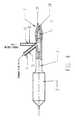
- FIG. 1is a general diagrammatic overview of an embodiment of a system for the removal of tissue with a combination of ultrasonic and cryogenic energy.
- FIG. 2shows an apparatus in accordance with present invention and a plot of the amplitude of the mechanical vibration of the ultrasonic horn and ultrasonic tip elicited by the transducer.
- FIG. 3shows an alternative embodiment of an apparatus in accordance with the present invention comprising a narrow elongated a chamber extending towards the distal end the ultrasonic tip.
- FIG. 4illustrates an alternative embodiment of an apparatus in accordance with the present invention comprising a cryogenic fluid outlet tube defining an interior passage.
- FIG. 5( a )is a side view of a chamber defined by the body of the ultrasonic tip.
- FIG. 5( b )shows a cross-section of an embodiment of the ultrasonic tip with two chambers.
- FIG. 6illustrates cross-sectional views of different possible embodiments of the distal end of the ultrasonic tip.
- FIG. 7illustrates the delivery of cryogenic fluid through a lumen passing through the center of the ultrasonic transducer and the horn before connecting to a chamber within the body of the ultrasonic tip.
- FIG. 8illustrates an alternative embodiment of the ultrasonic tip comprising an orifice between a chamber within the ultrasonic tip and the distal end of the ultrasonic tip.
- FIG. 9illustrates an embodiment of the delivery of cryogenic and ultrasonic energy to the tissue through an accumulation of frost positioned between radiation surface and the tissue.
- FIG. 10illustrates an embodiment of the delivery of ultrasonic energy to the tissue through a cryogenic spray emitted toward the tissue from the radiation surface.
- FIG. 11presents a three-dimensional view of an alternative embodiment of the ultrasonic tip comprising multiple orifices on distal end of the ultrasonic tip.
- FIG. 12shows a backwards cone shaped distal end focusing ultrasonic energy on a focal point.
- FIG. 13shows a concave distal end focusing ultrasonic energy on focal point.
- the present inventionis directed towards apparatuses and methods for the selective ablation of unwanted and/or diseased tissue by delivering ultrasonic and cryogenic energies simultaneously and/or sequentially to the tissue to be ablated.
- Embodiments of the present inventionmay result in a highly controllable and precise ablation of tissue.
- FIG. 1A general view of an embodiment of one apparatus 10 in accordance with the present invention is depicted in FIG. 1 .
- the apparatus of the present invention 10may be a hand held device with a distal ultrasonic tip 1 .
- Ultrasonic tip 1may be used to deliver cryogenic and ultrasonic energy to the tissue area 9 .
- Ultrasonic tip 1comprises a body defining one or more interior chambers 7 into which cryogenic fluid 20 flows.
- Cryogenic fluid 20may be a liquid and/or gas.
- One example of possible cryogenic fluidis liquid nitrogen.
- Other suitable cryogenic fluidsare readily recognizable by people of ordinary skill in the art.
- Cryogenic fluid 20may be delivered to the interior chambers 7 from a source 5 through delivery tube 4 .
- Delivery tube 4is attached to the ultrasonic tip 1 at the inlet tube 16 . Defining an interior passage 17 , inlet tube 16 connects delivery tube 4 to chambers 7 .
- Ultrasonic transducer 3may be connected to an ultrasound generator 6 by a cable 11 .
- Ultrasonic tip 1provides an ultrasonically active distal end 14 and/or cryogenic energy to tissue 9 through direct contact or through accumulation of frost 22 .
- Creating accumulation of frost 22 on distal end 14 of the ultrasonic tip 1may be accomplished by allowing moisture from the air to condense and freeze on distal end 14 .
- a substancesuch as, but not limited, water may be placed on distal end 14 and allowed to freeze.
- Ultrasonic tip 1is usually made from a metal such as titanium. Ultrasonic tip 1 may also be made from plastic and disposed of after treatment. Ultrasonic tip 1 may be excited by ultrasonic transducer 3 . Ultrasonic tip 1 may be connected to ultrasonic transducer 3 through an ultrasonic horn 2 . Ultrasonic tip 1 may be a separate piece attachable to ultrasonic horn 2 . Alternatively, ultrasonic tip 1 and ultrasonic horn 2 may form a single piece. Ultrasonic transducer 3 typically receives power from generator 6 through cable 11 . Ultrasonic transducer 3 may be pulsed according to a drive signal generated by generator 6 and transmitted to ultrasonic transducer 3 by cable 11 .
- the drive signalmay be rectangular, trapezoidal, sinusoidal, or other signal types readily recognizable by those skilled in the art.
- Ultrasonic transducer 3may be made to operate a frequency of approximately 18 KHz to approximately 20 MHz. The preferred frequency of operation is approximately 20 KHz to approximately 60 KHz. The recommended frequency of operation is approximately 35 KHz.
- the amplitude of the ultrasonic waves generated by transducer 3may be approximately 1 micron to approximately 200 microns. The preferred amplitude of the ultrasonic waves generated by transducer 3 is approximately 50 microns.
- FIG. 2shows an apparatus in accordance with present invention and a plot of the amplitude of the mechanical vibration of ultrasonic horn 2 and ultrasonic tip 1 elicited by transducer 3 .
- Delivery tube 16defines interior passage 17 , which opens into chamber 7 .
- Delivery tube 16is attached to ultrasonic horn 2 approximately at the mechanical resonance node 28 .
- a resonance is nodeis a point where the vibration amplitude of ultrasonic horn 2 or tip 1 is zero.
- FIG. 3shows an alternative embodiment of an apparatus in accordance with the present invention.
- Ultrasonic tip 1in the depicted embodiment, comprises a narrow elongated chamber 7 extending towards distal end 14 .
- Providing more than one chamber 7may increase the efficacy of cryogenic ablation.
- Chamber 7may direct cryogenic fluid through one or more orifice 12 in distal end 14 ( FIGS. 8 , 9 , and 10 ) or one the radial surface of ultrasonic tip 1 ( FIG. 11 ).
- FIG. 4illustrates an alternative embodiment of an apparatus in accordance with the present invention comprising a cryogenic fluid outlet tube 18 defining an interior passage 19 . Permitting the escape of cryogenic fluid from chamber 7 , tube 18 enables the circulation of cryogenic fluid through chamber 7 .
- FIG. 5( a )is a side view of a chamber 7 defined by body 30 of ultrasonic tip 1 .
- FIG. 5( a )also shows a channel 32 extending through the distal portion of ultrasonic tip 1 and in fluid communication with chamber 7 .
- a plurality of tubular passages 34are also defined by the body 30 . Emanating from chamber 7 and extending towards distal end 14 , tubular passages 34 may allow cryogenic fluid 20 to approach the distal end 14 while the maintaining structural integrity of body 30 .
- FIG. 5( b )shows a cross-section of an embodiment of ultrasonic tip 1 with two chambers 7 .
- the use of multiple chambers 7may improve circulation of a cryogenic fluid.
- FIGS. 6( a ) to 6 ( i )are cross-sectional views of different possible embodiments of distal end 14 .
- a rounded or oval distal end, depicted in FIG. 6( a )may be useful for the ablation of large regions of tissue.
- a sharp cone distal end, depicted in FIG. 6( b )may be useful the precise ablation of small regions of tissue.
- Flat distal ends, depicted in FIGS. 6( c ), 6 ( d ), 6 ( e ), and 6 ( f ),may be useful localized tissue ablation.
- FIG. 6( g )shows a toothed distal end.
- a disposable plastic cover 26 matching the geometric conformation of distal end 14may be used to cover distal end 14 .
- FIG. 7illustrates the delivery of cryogenic fluid through a lumen 34 passing through the center of ultrasonic transducer 3 and horn 2 before connecting to chamber 7 .
- This particular embodimentmay offer manufacturing advantages readily recognizable to those of ordinary skill in the art.
- FIG. 8illustrates an alternative embodiment of ultrasonic tip 1 comprising orifice 12 between chamber 7 and distal end 14 .
- cryogenic fluid 20emanates from distal end 14 , as shown in FIG. 10 .
- Spraying the cryogenic fluid 20 on tissue 9may allow for the creation of an accumulation of frost 22 on tissue 9 .
- This embodimentmay also allow for the creation of an accumulation of frost 22 on distal end 14 , as shown in FIG. 9 .
- FIG. 11presents a three-dimensional view of an alternative embodiment of ultrasonic tip 1 comprising multiple orifices 12 on distal end 14 .
- This embodimentmay be useful for the ablation of tissue forming various lumens in the body such as, but not limited to, bloods vessels.
- FIG. 12shows a backwards cone shaped distal end 14 focusing ultrasonic energy on a focal point 44 .
- FIG. 13shows a concave distal end 14 focusing ultrasonic energy on focal point 44 .
- a method in accordance with the present inventioncomprises the steps of transmitting ultrasonic energy to and transferring thermal energy from a tissue to be ablated.
- the transfer of thermal energy from the tissuemay proceed, follow, and/or occur simultaneously with the transmission of ultrasonic energy to tissue.
- Transferring thermal energy from the tissuemay be accomplished by providing cryogenic fluid 20 to distal end 14 and placing distal end 14 proximate to and/or in contact with the tissue to be ablated.
- Transmitting ultrasonic energy to the tissuemay be accomplished by exciting distal end 14 by activating transducer 3 and placing distal end 14 proximate to and/or in contact with the tissue.
- tissue 9 distal end 14should remain proximate to and/or in contact with the tissue until the unwanted tissue is ablated.
- cryogenic energy and the ultrasonic energymay be applied sequentially to the tissue to be ablated.
- a sequential applicationmay begin by exciting distal end 14 , placing the distal end 14 proximate to and/or in contact with the tissue 9 , and then providing cryogenic fluid to the distal end 14 .
- the sequencemay be reversed, in which case the sequence would begin by providing cryogenic fluid 20 to the distal end 14 , allowing an accumulation of frost 22 to form on the distal end 14 , placing the distal end 14 proximate to and/or in contact with the tissue 9 , and then activating the ultrasonic transducer.
- Combinations of sequential applications of cryogenic and ultrasonic energy and the simultaneous application of cryogenic and ultrasonic energymay be during ablation of tissue 9 as would be recognized by those skilled in the art.
- thermal energymay be transferred away from the tissue by spraying the tissue 9 with a spray of cryogenic fluid 20 emanating from orifice 12 in distal end 14 .
- Exciting distal end 14 as cryogenic fluid 20 sprays from office 12 onto tissue 9may enable the enable the simultaneous delivery of cryogenic and ultrasonic energy.
- frost 22may be used a conduit for the transmission of ultrasonic energy to tissue 9 from distal end 14 and/or the transfer of thermal energy from tissue 9 to distal end 14 .
- cryogenic energy to a tissueis synonymous with transferring cryogenic away from a tissue.
Landscapes
- Health & Medical Sciences (AREA)
- Surgery (AREA)
- Life Sciences & Earth Sciences (AREA)
- Engineering & Computer Science (AREA)
- Nuclear Medicine, Radiotherapy & Molecular Imaging (AREA)
- Animal Behavior & Ethology (AREA)
- General Health & Medical Sciences (AREA)
- Public Health (AREA)
- Veterinary Medicine (AREA)
- Biomedical Technology (AREA)
- Heart & Thoracic Surgery (AREA)
- Medical Informatics (AREA)
- Molecular Biology (AREA)
- Vascular Medicine (AREA)
- Otolaryngology (AREA)
- Mechanical Engineering (AREA)
- Orthopedic Medicine & Surgery (AREA)
- Thermal Sciences (AREA)
- Physics & Mathematics (AREA)
- Radiology & Medical Imaging (AREA)
- Anesthesiology (AREA)
- Hematology (AREA)
- Surgical Instruments (AREA)
Abstract
Description
Claims (16)
Priority Applications (4)
| Application Number | Priority Date | Filing Date | Title |
|---|---|---|---|
| US11/737,112US7842032B2 (en) | 2005-10-13 | 2007-04-18 | Apparatus and methods for the selective removal of tissue |
| PCT/US2008/060946WO2008131312A1 (en) | 2007-04-18 | 2008-04-18 | Apparatus and methods for the selective removal of tissue |
| JP2010504304AJP2010524592A (en) | 2007-04-18 | 2008-04-18 | Apparatus and method for selective tissue removal |
| KR1020097023104AKR20100094340A (en) | 2007-04-18 | 2008-04-18 | Apparatus and methods for the selective removal of tissue |
Applications Claiming Priority (2)
| Application Number | Priority Date | Filing Date | Title |
|---|---|---|---|
| US11/250,870US7572268B2 (en) | 2005-10-13 | 2005-10-13 | Apparatus and methods for the selective removal of tissue using combinations of ultrasonic energy and cryogenic energy |
| US11/737,112US7842032B2 (en) | 2005-10-13 | 2007-04-18 | Apparatus and methods for the selective removal of tissue |
Related Parent Applications (1)
| Application Number | Title | Priority Date | Filing Date |
|---|---|---|---|
| US11/250,870Continuation-In-PartUS7572268B2 (en) | 2005-10-13 | 2005-10-13 | Apparatus and methods for the selective removal of tissue using combinations of ultrasonic energy and cryogenic energy |
Publications (2)
| Publication Number | Publication Date |
|---|---|
| US20070233054A1 US20070233054A1 (en) | 2007-10-04 |
| US7842032B2true US7842032B2 (en) | 2010-11-30 |
Family
ID=39629133
Family Applications (1)
| Application Number | Title | Priority Date | Filing Date |
|---|---|---|---|
| US11/737,112Active - Reinstated2028-03-26US7842032B2 (en) | 2005-10-13 | 2007-04-18 | Apparatus and methods for the selective removal of tissue |
Country Status (4)
| Country | Link |
|---|---|
| US (1) | US7842032B2 (en) |
| JP (1) | JP2010524592A (en) |
| KR (1) | KR20100094340A (en) |
| WO (1) | WO2008131312A1 (en) |
Cited By (3)
| Publication number | Priority date | Publication date | Assignee | Title |
|---|---|---|---|---|
| US20080306501A1 (en)* | 2002-08-07 | 2008-12-11 | Celleration, Inc. | Device and method for ultrasound wound debridement |
| US20110224761A1 (en)* | 2008-04-01 | 2011-09-15 | The General Hospital Corporation | Method and apparatus for cooling biological tissue |
| US11980383B2 (en) | 2019-12-24 | 2024-05-14 | Farrow Medtech Llc | Wound-care apparatus and method for cleansing, desloughing, and debriding wounds |
Families Citing this family (26)
| Publication number | Priority date | Publication date | Assignee | Title |
|---|---|---|---|---|
| US20070031611A1 (en)* | 2005-08-04 | 2007-02-08 | Babaev Eilaz P | Ultrasound medical stent coating method and device |
| US7842032B2 (en)* | 2005-10-13 | 2010-11-30 | Bacoustics, Llc | Apparatus and methods for the selective removal of tissue |
| US7943352B2 (en) | 2006-03-29 | 2011-05-17 | Bacoustics, Llc | Apparatus and methods for vaccine development using ultrasound technology |
| US7846341B2 (en)* | 2006-12-04 | 2010-12-07 | Bacoustics, Llc | Method of ultrasonically treating a continuous flow of fluid |
| US20080243047A1 (en)* | 2007-03-27 | 2008-10-02 | Babaev Eilaz P | Ultrasound wound care device |
| US20090198157A1 (en)* | 2008-02-01 | 2009-08-06 | Eilaz Babaev | Ultrasound moxibustion method and device |
| US8016208B2 (en) | 2008-02-08 | 2011-09-13 | Bacoustics, Llc | Echoing ultrasound atomization and mixing system |
| US7950594B2 (en) | 2008-02-11 | 2011-05-31 | Bacoustics, Llc | Mechanical and ultrasound atomization and mixing system |
| US7830070B2 (en)* | 2008-02-12 | 2010-11-09 | Bacoustics, Llc | Ultrasound atomization system |
| WO2009149042A2 (en)* | 2008-06-03 | 2009-12-10 | Eilaz Babaev | Ultrasonic endometrial cryoablation device |
| EP2837348B1 (en)* | 2008-06-11 | 2020-04-08 | CryoConcepts LP | Cryo-surgical methods of use |
| US8512715B2 (en)* | 2008-08-14 | 2013-08-20 | The Cleveland Clinic Foundation | Apparatus and method for treating a neuromuscular defect |
| US20100106063A1 (en)* | 2008-10-29 | 2010-04-29 | Cabochon Aesthetics, Inc. | Ultrasound Enhancing Target for Treating Subcutaneous Tissue |
| DE102008054083A1 (en)* | 2008-10-31 | 2010-05-12 | Theuer, Axel E., Prof. Dr.-Ing. habil. | Medical device for the treatment of tumor tissue |
| US9655641B2 (en) | 2013-09-11 | 2017-05-23 | Covidien Lp | Ultrasonic surgical instrument with cooling system |
| US9622767B2 (en) | 2013-09-11 | 2017-04-18 | Covidien Lp | Ultrasonic surgical instrument with cooling system |
| US9764166B2 (en) | 2013-09-11 | 2017-09-19 | Covidien Lp | Ultrasonic surgical instrument with cooling system |
| US12214222B2 (en) | 2013-09-11 | 2025-02-04 | Covidien Lp | Ultrasonic surgical instrument with cooling system |
| EP3061415B8 (en)* | 2015-02-24 | 2017-11-22 | Covidien LP | Ultrasonic surgical instrument with cooling system |
| US10342566B2 (en) | 2016-03-29 | 2019-07-09 | Covidien Lp | Devices, systems, and methods for cooling a surgical instrument |
| US10456156B2 (en) | 2016-03-29 | 2019-10-29 | Covidien Lp | Devices, systems, and methods for cooling a surgical instrument |
| US11071566B2 (en)* | 2016-08-24 | 2021-07-27 | Covidien Lp | Introducing trocar with cryo-fixation of access cannula |
| US11534231B2 (en) | 2017-08-22 | 2022-12-27 | CovidienLP | Energy-based surgical instruments and systems configured to minimize thermal spread |
| US11844563B2 (en) | 2019-11-19 | 2023-12-19 | Covidien Lp | Energy-based surgical instruments incorporating cooling features |
| US12414793B2 (en) | 2021-01-06 | 2025-09-16 | Covidien Lp | Devices, systems, and methods of manufacturing fluid-cooled ultrasonic surgical instruments |
| WO2022193118A1 (en)* | 2021-03-16 | 2022-09-22 | 深圳市港基电技术有限公司 | Ultrasonic drive circuit |
Citations (51)
| Publication number | Priority date | Publication date | Assignee | Title |
|---|---|---|---|---|
| US3220414A (en) | 1962-04-30 | 1965-11-30 | Union Carbide Corp | Surgical cannula |
| US3237623A (en) | 1963-02-04 | 1966-03-01 | George A D Gordon | Apparatus for destroying limited groups of cells |
| US3589363A (en) | 1967-07-25 | 1971-06-29 | Cavitron Corp | Material removal apparatus and method employing high frequency vibrations |
| US3889680A (en) | 1974-02-07 | 1975-06-17 | Armao T A | Cryoadhesion preventing cryosurgical instruments |
| US4015606A (en) | 1975-09-09 | 1977-04-05 | Dynatech Corporation | Method and means for controlling the freeze zone of a cryosurgical probe |
| US4082096A (en) | 1973-12-10 | 1978-04-04 | Benson Jerrel W | Cryosurgical system |
| US4528979A (en) | 1982-03-18 | 1985-07-16 | Kievsky Nauchno-Issledovatelsky Institut Otolaringologii Imeni Professora A.S. Kolomiiobenka | Cryo-ultrasonic surgical instrument |
| US4823790A (en) | 1985-11-20 | 1989-04-25 | Alperovich Boris I | Cryogenic-and-ultrasonic scalpel |
| US4832022A (en) | 1986-05-26 | 1989-05-23 | Tomsky Gosudarstvenny Universitet Im. Kuibysheva | Cryogenic ultrasonic scalpel |
| US4946460A (en) | 1989-04-26 | 1990-08-07 | Cryo Instruments, Inc. | Apparatus for cryosurgery |
| US5078713A (en) | 1988-12-01 | 1992-01-07 | Spembly Medical Limited | Cryosurgical probe |
| US5108390A (en) | 1988-11-14 | 1992-04-28 | Frigitronics, Inc. | Flexible cryoprobe |
| US5139496A (en) | 1990-12-20 | 1992-08-18 | Hed Aharon Z | Ultrasonic freeze ablation catheters and probes |
| US5334181A (en) | 1990-09-26 | 1994-08-02 | Cryomedical Sciences, Inc. | Cryosurgical system for destroying tumors by freezing |
| US5433717A (en) | 1993-03-23 | 1995-07-18 | The Regents Of The University Of California | Magnetic resonance imaging assisted cryosurgery |
| US5452582A (en) | 1994-07-06 | 1995-09-26 | Apd Cryogenics, Inc. | Cryo-probe |
| US5520682A (en) | 1991-09-06 | 1996-05-28 | Cryomedical Sciences, Inc. | Cryosurgical instrument with vent means and method using same |
| US5649936A (en) | 1995-09-19 | 1997-07-22 | Real; Douglas D. | Stereotactic guide apparatus for use with neurosurgical headframe |
| US5716353A (en) | 1996-05-03 | 1998-02-10 | Urds, Corp. | Cryosurgical instrument |
| US5899898A (en) | 1997-02-27 | 1999-05-04 | Cryocath Technologies Inc. | Cryosurgical linear ablation |
| US5906612A (en) | 1997-09-19 | 1999-05-25 | Chinn; Douglas O. | Cryosurgical probe having insulating and heated sheaths |
| US5913885A (en) | 1991-05-22 | 1999-06-22 | Life Science Holdings, Inc. | Brain cooling device and method for cooling |
| US5916242A (en) | 1996-11-04 | 1999-06-29 | Schwartz; George R. | Apparatus for rapid cooling of the brain and method of performing same |
| US5957963A (en) | 1998-01-23 | 1999-09-28 | Del Mar Medical Technologies, Inc. | Selective organ hypothermia method and apparatus |
| US6030412A (en) | 1991-05-22 | 2000-02-29 | Life Science Holdings, Inc. | Apparatus and method for cooling the brain, brain stem and associated neurologic tissues |
| US6039730A (en) | 1996-06-24 | 2000-03-21 | Allegheny-Singer Research Institute | Method and apparatus for cryosurgery |
| US6041787A (en) | 1997-03-17 | 2000-03-28 | Rubinsky; Boris | Use of cryoprotective agent compounds during cryosurgery |
| US6042579A (en) | 1997-04-30 | 2000-03-28 | Medtronic, Inc. | Techniques for treating neurodegenerative disorders by infusion of nerve growth factors into the brain |
| US6045532A (en) | 1998-02-20 | 2000-04-04 | Arthrocare Corporation | Systems and methods for electrosurgical treatment of tissue in the brain and spinal cord |
| US6074412A (en) | 1996-07-23 | 2000-06-13 | Endocare, Inc. | Cryoprobe |
| US6083166A (en) | 1997-12-02 | 2000-07-04 | Situs Corporation | Method and apparatus for determining a measure of tissue manipulation |
| US6096068A (en) | 1998-01-23 | 2000-08-01 | Innercool Therapies, Inc. | Selective organ cooling catheter and method of using the same |
| US6106518A (en) | 1998-04-09 | 2000-08-22 | Cryocath Technologies, Inc. | Variable geometry tip for a cryosurgical ablation device |
| US6126684A (en) | 1998-04-21 | 2000-10-03 | The Regents Of The University Of California | Indwelling heat exchange catheter and method of using same |
| US6149677A (en) | 1998-03-31 | 2000-11-21 | Innercool Therapies, Inc. | Circulating fluid hypothermia method |
| US6245095B1 (en) | 1998-03-24 | 2001-06-12 | Innercool Therapies, Inc. | Method and apparatus for location and temperature specific drug action such as thrombolysis |
| US6248126B1 (en) | 1998-01-12 | 2001-06-19 | The Johns Hopkins University | Technique for using heat flow management to treat brain disorders |
| US6280441B1 (en) | 1997-12-15 | 2001-08-28 | Sherwood Services Ag | Apparatus and method for RF lesioning |
| US6280439B1 (en)* | 1999-07-12 | 2001-08-28 | Cryocath Technologies, Inc. | Adjustable position injection tubing |
| WO2001076517A2 (en) | 2000-04-07 | 2001-10-18 | The General Hospital Corporation D/B/A Massachusetts General Hospital | Methods and apparatus for thermally affecting tissue |
| US6386202B1 (en) | 1996-11-27 | 2002-05-14 | The Regents Of The University Of California | Method for treating ischemic brain stroke |
| US6413263B1 (en) | 2000-04-24 | 2002-07-02 | Axon Instruments, Inc. | Stereotactic probe holder and method of use |
| US6475212B2 (en) | 1996-12-26 | 2002-11-05 | Cryogen, Inc. | Cryosurgical probe with sheath |
| US6546932B1 (en) | 1999-04-05 | 2003-04-15 | Cryocath Technologies Inc. | Cryogenic method and apparatus for promoting angiogenesis |
| US6551309B1 (en) | 2000-09-14 | 2003-04-22 | Cryoflex, Inc. | Dual action cryoprobe and methods of using the same |
| US6565556B1 (en) | 1999-02-12 | 2003-05-20 | Nikolai Korpan | Device for carrying out cryosurgical interventions, especially for treating tumors |
| US6582368B2 (en) | 1998-10-01 | 2003-06-24 | Paul F. Zupkas | Medical instrument sheath comprising a flexible ultrasound transducer |
| US6648880B2 (en) | 2001-02-16 | 2003-11-18 | Cryocath Technologies Inc. | Method of using cryotreatment to treat brain tissue |
| US6663554B2 (en) | 2001-04-23 | 2003-12-16 | Advanced Medical Applications, Inc. | Ultrasonic method and device for wound treatment |
| US6858025B2 (en) | 2002-08-06 | 2005-02-22 | Medically Advanced Designs, Llc | Cryo-surgical apparatus and method of use |
| US6936045B2 (en) | 2001-09-20 | 2005-08-30 | Endocare, Inc. | Malleable cryosurgical probe |
Family Cites Families (3)
| Publication number | Priority date | Publication date | Assignee | Title |
|---|---|---|---|---|
| US6527765B2 (en)* | 2000-10-06 | 2003-03-04 | Charles D. Kelman | Cryogenic surgical system and method of use in removal of tissue |
| US7842032B2 (en)* | 2005-10-13 | 2010-11-30 | Bacoustics, Llc | Apparatus and methods for the selective removal of tissue |
| US7572268B2 (en)* | 2005-10-13 | 2009-08-11 | Bacoustics, Llc | Apparatus and methods for the selective removal of tissue using combinations of ultrasonic energy and cryogenic energy |
- 2007
- 2007-04-18USUS11/737,112patent/US7842032B2/enactiveActive - Reinstated
- 2008
- 2008-04-18KRKR1020097023104Apatent/KR20100094340A/ennot_activeWithdrawn
- 2008-04-18JPJP2010504304Apatent/JP2010524592A/enactivePending
- 2008-04-18WOPCT/US2008/060946patent/WO2008131312A1/enactiveApplication Filing
Patent Citations (54)
| Publication number | Priority date | Publication date | Assignee | Title |
|---|---|---|---|---|
| US3220414A (en) | 1962-04-30 | 1965-11-30 | Union Carbide Corp | Surgical cannula |
| US3237623A (en) | 1963-02-04 | 1966-03-01 | George A D Gordon | Apparatus for destroying limited groups of cells |
| US3589363A (en) | 1967-07-25 | 1971-06-29 | Cavitron Corp | Material removal apparatus and method employing high frequency vibrations |
| US4082096A (en) | 1973-12-10 | 1978-04-04 | Benson Jerrel W | Cryosurgical system |
| US3889680A (en) | 1974-02-07 | 1975-06-17 | Armao T A | Cryoadhesion preventing cryosurgical instruments |
| US4015606A (en) | 1975-09-09 | 1977-04-05 | Dynatech Corporation | Method and means for controlling the freeze zone of a cryosurgical probe |
| US4528979A (en) | 1982-03-18 | 1985-07-16 | Kievsky Nauchno-Issledovatelsky Institut Otolaringologii Imeni Professora A.S. Kolomiiobenka | Cryo-ultrasonic surgical instrument |
| US4823790A (en) | 1985-11-20 | 1989-04-25 | Alperovich Boris I | Cryogenic-and-ultrasonic scalpel |
| US4832022A (en) | 1986-05-26 | 1989-05-23 | Tomsky Gosudarstvenny Universitet Im. Kuibysheva | Cryogenic ultrasonic scalpel |
| US5108390A (en) | 1988-11-14 | 1992-04-28 | Frigitronics, Inc. | Flexible cryoprobe |
| US5078713A (en) | 1988-12-01 | 1992-01-07 | Spembly Medical Limited | Cryosurgical probe |
| US4946460A (en) | 1989-04-26 | 1990-08-07 | Cryo Instruments, Inc. | Apparatus for cryosurgery |
| US5334181A (en) | 1990-09-26 | 1994-08-02 | Cryomedical Sciences, Inc. | Cryosurgical system for destroying tumors by freezing |
| US5139496A (en) | 1990-12-20 | 1992-08-18 | Hed Aharon Z | Ultrasonic freeze ablation catheters and probes |
| US5913885A (en) | 1991-05-22 | 1999-06-22 | Life Science Holdings, Inc. | Brain cooling device and method for cooling |
| US6030412A (en) | 1991-05-22 | 2000-02-29 | Life Science Holdings, Inc. | Apparatus and method for cooling the brain, brain stem and associated neurologic tissues |
| US5520682A (en) | 1991-09-06 | 1996-05-28 | Cryomedical Sciences, Inc. | Cryosurgical instrument with vent means and method using same |
| US5433717A (en) | 1993-03-23 | 1995-07-18 | The Regents Of The University Of California | Magnetic resonance imaging assisted cryosurgery |
| US5452582A (en) | 1994-07-06 | 1995-09-26 | Apd Cryogenics, Inc. | Cryo-probe |
| US5649936A (en) | 1995-09-19 | 1997-07-22 | Real; Douglas D. | Stereotactic guide apparatus for use with neurosurgical headframe |
| US5716353A (en) | 1996-05-03 | 1998-02-10 | Urds, Corp. | Cryosurgical instrument |
| US6039730A (en) | 1996-06-24 | 2000-03-21 | Allegheny-Singer Research Institute | Method and apparatus for cryosurgery |
| US6786902B1 (en) | 1996-06-24 | 2004-09-07 | Allegheny-Singer Research Institute | Method and apparatus for cryosurgery |
| US6074412A (en) | 1996-07-23 | 2000-06-13 | Endocare, Inc. | Cryoprobe |
| US5916242A (en) | 1996-11-04 | 1999-06-29 | Schwartz; George R. | Apparatus for rapid cooling of the brain and method of performing same |
| US6386202B1 (en) | 1996-11-27 | 2002-05-14 | The Regents Of The University Of California | Method for treating ischemic brain stroke |
| US6475212B2 (en) | 1996-12-26 | 2002-11-05 | Cryogen, Inc. | Cryosurgical probe with sheath |
| US5899899A (en) | 1997-02-27 | 1999-05-04 | Cryocath Technologies Inc. | Cryosurgical linear ablation structure |
| US5899898A (en) | 1997-02-27 | 1999-05-04 | Cryocath Technologies Inc. | Cryosurgical linear ablation |
| US6041787A (en) | 1997-03-17 | 2000-03-28 | Rubinsky; Boris | Use of cryoprotective agent compounds during cryosurgery |
| US6042579A (en) | 1997-04-30 | 2000-03-28 | Medtronic, Inc. | Techniques for treating neurodegenerative disorders by infusion of nerve growth factors into the brain |
| US5906612A (en) | 1997-09-19 | 1999-05-25 | Chinn; Douglas O. | Cryosurgical probe having insulating and heated sheaths |
| US6083166A (en) | 1997-12-02 | 2000-07-04 | Situs Corporation | Method and apparatus for determining a measure of tissue manipulation |
| US6280441B1 (en) | 1997-12-15 | 2001-08-28 | Sherwood Services Ag | Apparatus and method for RF lesioning |
| US6248126B1 (en) | 1998-01-12 | 2001-06-19 | The Johns Hopkins University | Technique for using heat flow management to treat brain disorders |
| US6051019A (en) | 1998-01-23 | 2000-04-18 | Del Mar Medical Technologies, Inc. | Selective organ hypothermia method and apparatus |
| US5957963A (en) | 1998-01-23 | 1999-09-28 | Del Mar Medical Technologies, Inc. | Selective organ hypothermia method and apparatus |
| US6096068A (en) | 1998-01-23 | 2000-08-01 | Innercool Therapies, Inc. | Selective organ cooling catheter and method of using the same |
| US6045532A (en) | 1998-02-20 | 2000-04-04 | Arthrocare Corporation | Systems and methods for electrosurgical treatment of tissue in the brain and spinal cord |
| US6245095B1 (en) | 1998-03-24 | 2001-06-12 | Innercool Therapies, Inc. | Method and apparatus for location and temperature specific drug action such as thrombolysis |
| US6149677A (en) | 1998-03-31 | 2000-11-21 | Innercool Therapies, Inc. | Circulating fluid hypothermia method |
| US6106518A (en) | 1998-04-09 | 2000-08-22 | Cryocath Technologies, Inc. | Variable geometry tip for a cryosurgical ablation device |
| US6126684A (en) | 1998-04-21 | 2000-10-03 | The Regents Of The University Of California | Indwelling heat exchange catheter and method of using same |
| US6582368B2 (en) | 1998-10-01 | 2003-06-24 | Paul F. Zupkas | Medical instrument sheath comprising a flexible ultrasound transducer |
| US6565556B1 (en) | 1999-02-12 | 2003-05-20 | Nikolai Korpan | Device for carrying out cryosurgical interventions, especially for treating tumors |
| US6546932B1 (en) | 1999-04-05 | 2003-04-15 | Cryocath Technologies Inc. | Cryogenic method and apparatus for promoting angiogenesis |
| US6280439B1 (en)* | 1999-07-12 | 2001-08-28 | Cryocath Technologies, Inc. | Adjustable position injection tubing |
| WO2001076517A2 (en) | 2000-04-07 | 2001-10-18 | The General Hospital Corporation D/B/A Massachusetts General Hospital | Methods and apparatus for thermally affecting tissue |
| US6413263B1 (en) | 2000-04-24 | 2002-07-02 | Axon Instruments, Inc. | Stereotactic probe holder and method of use |
| US6551309B1 (en) | 2000-09-14 | 2003-04-22 | Cryoflex, Inc. | Dual action cryoprobe and methods of using the same |
| US6648880B2 (en) | 2001-02-16 | 2003-11-18 | Cryocath Technologies Inc. | Method of using cryotreatment to treat brain tissue |
| US6663554B2 (en) | 2001-04-23 | 2003-12-16 | Advanced Medical Applications, Inc. | Ultrasonic method and device for wound treatment |
| US6936045B2 (en) | 2001-09-20 | 2005-08-30 | Endocare, Inc. | Malleable cryosurgical probe |
| US6858025B2 (en) | 2002-08-06 | 2005-02-22 | Medically Advanced Designs, Llc | Cryo-surgical apparatus and method of use |
Non-Patent Citations (1)
| Title |
|---|
| Mark D. Andrews, Cryosurgery for Common Skin Conditions, American Family Physician, vol. 69 (10), May 15, 2005, pp. 2365-2372. |
Cited By (3)
| Publication number | Priority date | Publication date | Assignee | Title |
|---|---|---|---|---|
| US20080306501A1 (en)* | 2002-08-07 | 2008-12-11 | Celleration, Inc. | Device and method for ultrasound wound debridement |
| US20110224761A1 (en)* | 2008-04-01 | 2011-09-15 | The General Hospital Corporation | Method and apparatus for cooling biological tissue |
| US11980383B2 (en) | 2019-12-24 | 2024-05-14 | Farrow Medtech Llc | Wound-care apparatus and method for cleansing, desloughing, and debriding wounds |
Also Published As
| Publication number | Publication date |
|---|---|
| WO2008131312A1 (en) | 2008-10-30 |
| US20070233054A1 (en) | 2007-10-04 |
| KR20100094340A (en) | 2010-08-26 |
| JP2010524592A (en) | 2010-07-22 |
Similar Documents
| Publication | Publication Date | Title |
|---|---|---|
| US7842032B2 (en) | Apparatus and methods for the selective removal of tissue | |
| US7572268B2 (en) | Apparatus and methods for the selective removal of tissue using combinations of ultrasonic energy and cryogenic energy | |
| US7135029B2 (en) | Ultrasonic surgical instrument for intracorporeal sonodynamic therapy | |
| US6695781B2 (en) | Ultrasonic medical device for tissue remodeling | |
| JP2009539500A (en) | Tissue treatment apparatus and method using ultrasonic energy by direct contact | |
| US7662177B2 (en) | Apparatus and methods for pain relief using ultrasound waves in combination with cryogenic energy | |
| US20020156400A1 (en) | Ultrasonic method and device for wound treatment | |
| US20040158150A1 (en) | Apparatus and method for an ultrasonic medical device for tissue remodeling | |
| WO2001082778A3 (en) | Ablation system with visualization | |
| CN101522263A (en) | Portable ultrasound device for treating wounds | |
| JP2004538039A (en) | Ultrasonic wound treatment method and apparatus using standing wave | |
| US20060020231A1 (en) | Ultrasonic system for treatment of proctologic diseases and ultrasonic instrument for these purposes and ultrasonic proctologic set | |
| AU2001277279B9 (en) | Ultrasonic medical device for tissue remodeling | |
| US20090306550A1 (en) | Ultrasonic Endometrial Cryoablation Method | |
| US8048095B2 (en) | Ultrasound liquid blade scalpel device | |
| JP2008535564A (en) | Ultrasonic medical device and related methods of use | |
| US20090306694A1 (en) | Ultrasound Liquid Blade Scalpel Method | |
| RU2004122116A (en) | DEVICE FOR ULTRASONIC THERAPY | |
| US20090299235A1 (en) | Ultrasonic Endometrial Cryoablation Device | |
| US20060036191A1 (en) | Ultrasonic system for treatment of otolaryngologic diseases and ultrasonic instrument for these purposes and ultrasonic otolaryngologic set. | |
| US20060036192A1 (en) | Ultrasonic system for treatment of urologic diseases and ultrasonic instrument for these purposes and ultrasonic urologic set | |
| HK1120388A (en) | Apparatus and methods for the selective removal of tissue using combinations of ultrasonic energy and cryogenic energy | |
| US20100324481A1 (en) | Ultrasound pumping apparatus for use with the human body | |
| WO2009151996A2 (en) | Ultrasound liquid blade scalpel device | |
| WO2008022172A2 (en) | Apparatus and method for the treatment of tissue with ultrasound by direct contact |
Legal Events
| Date | Code | Title | Description |
|---|---|---|---|
| ZAAA | Notice of allowance and fees due | Free format text:ORIGINAL CODE: NOA | |
| ZAAB | Notice of allowance mailed | Free format text:ORIGINAL CODE: MN/=. | |
| STCF | Information on status: patent grant | Free format text:PATENTED CASE | |
| REMI | Maintenance fee reminder mailed | ||
| FPAY | Fee payment | Year of fee payment:4 | |
| SULP | Surcharge for late payment | ||
| FEPP | Fee payment procedure | Free format text:MAINTENANCE FEE REMINDER MAILED (ORIGINAL EVENT CODE: REM.) | |
| FEPP | Fee payment procedure | Free format text:7.5 YR SURCHARGE - LATE PMT W/IN 6 MO, SMALL ENTITY (ORIGINAL EVENT CODE: M2555); ENTITY STATUS OF PATENT OWNER: SMALL ENTITY | |
| MAFP | Maintenance fee payment | Free format text:PAYMENT OF MAINTENANCE FEE, 8TH YR, SMALL ENTITY (ORIGINAL EVENT CODE: M2552); ENTITY STATUS OF PATENT OWNER: SMALL ENTITY Year of fee payment:8 | |
| FEPP | Fee payment procedure | Free format text:MAINTENANCE FEE REMINDER MAILED (ORIGINAL EVENT CODE: REM.); ENTITY STATUS OF PATENT OWNER: SMALL ENTITY | |
| LAPS | Lapse for failure to pay maintenance fees | Free format text:PATENT EXPIRED FOR FAILURE TO PAY MAINTENANCE FEES (ORIGINAL EVENT CODE: EXP.); ENTITY STATUS OF PATENT OWNER: SMALL ENTITY | |
| STCH | Information on status: patent discontinuation | Free format text:PATENT EXPIRED DUE TO NONPAYMENT OF MAINTENANCE FEES UNDER 37 CFR 1.362 | |
| FP | Lapsed due to failure to pay maintenance fee | Effective date:20221130 | |
| FEPP | Fee payment procedure | Free format text:PETITION RELATED TO MAINTENANCE FEES FILED (ORIGINAL EVENT CODE: PMFP); ENTITY STATUS OF PATENT OWNER: SMALL ENTITY Free format text:SURCHARGE, PETITION TO ACCEPT PYMT AFTER EXP, UNINTENTIONAL. (ORIGINAL EVENT CODE: M2558); ENTITY STATUS OF PATENT OWNER: SMALL ENTITY | |
| MAFP | Maintenance fee payment | Free format text:PAYMENT OF MAINTENANCE FEE, 12TH YR, SMALL ENTITY (ORIGINAL EVENT CODE: M2553); ENTITY STATUS OF PATENT OWNER: SMALL ENTITY Year of fee payment:12 | |
| FEPP | Fee payment procedure | Free format text:PETITION RELATED TO MAINTENANCE FEES FILED (ORIGINAL EVENT CODE: PMFP); ENTITY STATUS OF PATENT OWNER: SMALL ENTITY | |
| PRDP | Patent reinstated due to the acceptance of a late maintenance fee | Effective date:20240129 | |
| FEPP | Fee payment procedure | Free format text:PETITION RELATED TO MAINTENANCE FEES GRANTED (ORIGINAL EVENT CODE: PMFG); ENTITY STATUS OF PATENT OWNER: SMALL ENTITY | |
| STCF | Information on status: patent grant | Free format text:PATENTED CASE |