US7842029B2 - Apparatus and method having a cooling material and reduced pressure to treat biological external tissue - Google Patents
Apparatus and method having a cooling material and reduced pressure to treat biological external tissueDownload PDFInfo
- Publication number
- US7842029B2 US7842029B2US11/024,340US2434004AUS7842029B2US 7842029 B2US7842029 B2US 7842029B2US 2434004 AUS2434004 AUS 2434004AUS 7842029 B2US7842029 B2US 7842029B2
- Authority
- US
- United States
- Prior art keywords
- external tissue
- biological external
- pressure
- inner chamber
- biological
- Prior art date
- Legal status (The legal status is an assumption and is not a legal conclusion. Google has not performed a legal analysis and makes no representation as to the accuracy of the status listed.)
- Expired - Fee Related, expires
Links
Images


Classifications
- A—HUMAN NECESSITIES
- A61—MEDICAL OR VETERINARY SCIENCE; HYGIENE
- A61B—DIAGNOSIS; SURGERY; IDENTIFICATION
- A61B18/00—Surgical instruments, devices or methods for transferring non-mechanical forms of energy to or from the body
- A61B18/18—Surgical instruments, devices or methods for transferring non-mechanical forms of energy to or from the body by applying electromagnetic radiation, e.g. microwaves
- A61B18/20—Surgical instruments, devices or methods for transferring non-mechanical forms of energy to or from the body by applying electromagnetic radiation, e.g. microwaves using laser
- A61B18/203—Surgical instruments, devices or methods for transferring non-mechanical forms of energy to or from the body by applying electromagnetic radiation, e.g. microwaves using laser applying laser energy to the outside of the body
- A—HUMAN NECESSITIES
- A61—MEDICAL OR VETERINARY SCIENCE; HYGIENE
- A61B—DIAGNOSIS; SURGERY; IDENTIFICATION
- A61B17/00—Surgical instruments, devices or methods
- A61B2017/00017—Electrical control of surgical instruments
- A61B2017/00022—Sensing or detecting at the treatment site
- A61B2017/00057—Light
- A—HUMAN NECESSITIES
- A61—MEDICAL OR VETERINARY SCIENCE; HYGIENE
- A61B—DIAGNOSIS; SURGERY; IDENTIFICATION
- A61B18/00—Surgical instruments, devices or methods for transferring non-mechanical forms of energy to or from the body
- A61B2018/00005—Cooling or heating of the probe or tissue immediately surrounding the probe
- A—HUMAN NECESSITIES
- A61—MEDICAL OR VETERINARY SCIENCE; HYGIENE
- A61B—DIAGNOSIS; SURGERY; IDENTIFICATION
- A61B18/00—Surgical instruments, devices or methods for transferring non-mechanical forms of energy to or from the body
- A61B2018/00315—Surgical instruments, devices or methods for transferring non-mechanical forms of energy to or from the body for treatment of particular body parts
- A61B2018/00452—Skin
- A61B2018/0047—Upper parts of the skin, e.g. skin peeling or treatment of wrinkles
- A—HUMAN NECESSITIES
- A61—MEDICAL OR VETERINARY SCIENCE; HYGIENE
- A61B—DIAGNOSIS; SURGERY; IDENTIFICATION
- A61B18/00—Surgical instruments, devices or methods for transferring non-mechanical forms of energy to or from the body
- A61B2018/00315—Surgical instruments, devices or methods for transferring non-mechanical forms of energy to or from the body for treatment of particular body parts
- A61B2018/00452—Skin
- A61B2018/00476—Hair follicles
- A—HUMAN NECESSITIES
- A61—MEDICAL OR VETERINARY SCIENCE; HYGIENE
- A61B—DIAGNOSIS; SURGERY; IDENTIFICATION
- A61B18/00—Surgical instruments, devices or methods for transferring non-mechanical forms of energy to or from the body
- A61B2018/00994—Surgical instruments, devices or methods for transferring non-mechanical forms of energy to or from the body combining two or more different kinds of non-mechanical energy or combining one or more non-mechanical energies with ultrasound
Definitions
- the present inventionrelates to methods and devices useful in modification, treatment, destruction, and/or removal of tissue.
- Devices utilized in dermatological treatmentsoften incorporate light based energy sources or high frequency rf electrical energy sources. Examples of such devices are described in U.S. Pat. No. 6,511,475. Some devices include both technologies.
- Lasers and light-based deviceshave been used for many years in the treatment of dermatological conditions. Soon after the laser was invented in 1957, medical researchers started to explore its use for a wide range of dermatological procedures. In recent years, especially since the mid-90's, the technology has been commercialized into numerous different devices that remove unwanted hair, wrinkles, fine lines and various facial blemishes (“skin rejuvenation”), tattoos, and vascular and pigmented lesions. Because of the short treatment time, virtually no patient “down-time” and fewer side effects, several of these laser- or light-based treatments have become more widely used than the conventional alternatives.
- Light energywhen applied directly to the human body, is absorbed by the target chromophore; by the hemoglobin in the blood; the water in the skin; the melanin in the skin; and/or by the melanin in the hair follicles, depending on the wavelength(s) of the light used.
- Lasers generating different wavelengths of lightwere found early on to have different properties, each being preferable for specific procedures.
- several manufacturershave also introduced devices that emit light of a wide range of wavelengths that practitioners then filter to select the appropriate wavelength for a specific treatment. These “multi-wavelength” or “multi-application” light-based devices have the advantage of performing several different aesthetic treatments, and thus costing the practitioner less than purchasing several lasers individually.
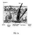
- FIG. 1 ais a diagram showing the various layers of the skin and potential targets for photo therapy and/or electrical therapy.
- light energyfirst impacts the skin, it encounters the epidermis, the outer most layer of skin.
- melaninthe brown pigmentation that most of us have in our skin. Darker individuals have more melanin than lighter ones. For very dark individuals, melanin may comprise more than 20% of the epidermis. For light skin individuals, melanin may comprise only 1 to 2% of the epidermis.
- the melaninmigrates from the cell and forms a protective umbrella over the fibroblasts and other cells in the skin.
- the melaninabsorbs harmful UVA and UVB radiation that can cause cell damage. It also absorbs visible light, absorbing blue light more than red light.
- the epidermisis very thin as it is only 50 to 100 microns in thickness. Consequently, despite the strong absorption by melanin, a reasonable percentage of the light passes through the epidermis into the upper layer of the dermis. For a fair skin person, as little as 15% of the light in the visible portion of the spectrum is absorbed in the epidermis. For a darker person, the percentage absorbed can be more than 50%.
- the dermal plexusAfter passing through the epidermis, the light impacts a region called the dermal plexus. This is a thin region at the outer most region of the dermis. It contains a high concentration of small capillary vessels that provide nourishment to the overlying epidermis. The blood in these vessels absorbs between 35% and 40% of the visible portion of the light that impacted the skin.
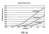
- FIG. 1 bshows the percentage of incident energy transmitted, as a function of wavelength, through the epidermis for three different skin types.
- the figureshows a low percentage of the incident energy in the visible portion of the spectrum is transmitted through the epidermis.
- the energy not transmittedis absorbed, resulting in a rise in temperature of the epidermis and possibly resulting in the burning of the tissue.
- FIG. 1 cshows the percentage of incident energy transmitted through the dermal plexus for two different levels of blood concentration (shown as ratios of blood to the rest of the tissue in a given volume).
- the energy not transmittedis absorbed and can produce burning. More importantly, the energy absorbed in the dermal plexus is not available to heat a target such as collagen or tattoo ink that is located beneath the dermal plexus. By reducing the concentration in half, the energy transmitted is doubled.
- rf electrical energyis also becoming common in devices used to treat wrinkles, unwanted hair and unwanted vascular lesions.
- One of the basic principles of electricityis an electric current passing through a resistive element generates heat in that element.
- the power dissipated in the elementis proportional to the square of the electrical current and also proportional to the resistance of the element.
- the heat generatedis the product of the power times the length of time the power is being dissipated.
- a second basic principle of electricityis the electric current seeks the path of least resistance. If two or more such paths exist, the current divides itself proportionally to the resistance of each path. For example, if two such paths exist and one path is twice the resistance of the other, twice the current will pass through the path with the lesser resistance than passes through the path with more resistance.
- the distribution of power and energyis also in the ratio of the resistances. In the current example, two times the power is dissipated in the lower resistance path than in the higher path. The path with the lesser resistance will heat at twice the rate as the higher resistance path.
- the various tissues and components of the bodyare the electrical resistors. As the rf current passes through these tissues, energy is dissipated and the temperature of the tissue rises. If the tissue is a blood vessel, it may reach a temperature at which the blood denatures and coagulates. If the tissue is collagen, it may reach a temperature at which the collagen denatures and is destroyed. The body's natural immune system removes the destroyed tissue, starting a process to regenerate new tissue.
- Tissues in the body with relatively high resistanceare bone, fat and the outer layer of the epidermis.
- Tissues with moderate resistanceare connective tissue and the dermis.
- the tissue with the lowest resistanceis the blood.
- high frequency electricityis used in dermatological applications, it tends to follow the pathways of the blood vessels, avoiding the fatty tissues and connective tissues.
- the apparatusesare typically (but not necessarily) handheld devices which apply energy (e.g., coherent and/or incoherent light) from one or more sources in the handheld device.
- the devicemay include a negative pressure conduit (e.g., a tube which couples the skin to a vacuum source/pump) which can be used to draw the skin into a region of the device. This will tend to stretch the skin and bring one or more targets (below the surface of the skin) closer to the surface so that these targets receive more incident energy as a result of being closer to the surface.
- the devicemay also include a pixilated display for displaying information (e.g., skin temperature, elapsed treatment time, etc.).
- the devicemay also include sensors (e.g., skin color sensors, temperature sensors, motion sensors, vapor pressure sensors, material sensors, and/or capacitance sensors), and may also include an object which is used to mechanically push the skin (thereby providing a positive pressure to a portion of the skin).
- a devicemay have multiple, different sources of energy. The sources of energy may, for example, be different laser diodes which emit light of different wavelengths.
- a devicemay include a pressure conduit which creates a positive pressure (e.g., a pressure above ambient atmospheric pressure). This pressure conduit may, in certain embodiments, be the same conduit which provides a vacuum or it may be a different, separate conduit.
- a handheld devicemay include the following features and/or a subset of these features: a negative pressure conduit (e.g., a tube coupled to a vacuum pump to generate a vacuum over a treatment area); a positive pressure conduit (e.g., a tube coupled to an air pump to allow the device to be released after a treatment and/or to “float” over the skin as the device is moved into a position over the skin); and an object to mechanically push the skin (e.g., a piston and/or plunger to push blood away from a treatment area just before exposing the area to energy); and multiple, different sources of energy (e.g., several light sources of different wavelengths and/or other properties); and one or more sensors (e.g., one or more skin color sensors and/or skin temperature sensors to provide feedback to a user, and/or to an automatically controlled processing system before, during, and/or after a treatment; and a pixilated
- a devicein one aspect includes a cavity which, when pressed against a biological external tissue forms a chamber against (or emncompassing) the biological external tissue.
- a devicemay include a material in the chamber to vaporize at the pressure below atmospheric pressure to prevent burning the biological external tissue.
- the materialmay be water, ethyl alcohol, and/or any material that has a vapor pressure below atmospheric pressure.
- a method to treat a targetincludes furnishing a material (e.g., a liquid) to a biological external tissue inside an inner chamber, applying an energy to the biological external tissue inside the inner chamber, and causing the material to evaporate.
- a materiale.g., a liquid
- the materialevaporates during application of the energy to treat the target.
- an outer portion of a device and an inner chamber of the deviceare applied to the biological external tissue such that the outer portion contacts the biological external tissue and the inner chamber occupies a space above a portion of the biological external tissue having the target.
- pressure within the inner chambermay be reduced to a first pressure that is below atmospheric pressure to bring at least some of the biological external tissue into the inner chamber and to also cause the material to evaporate, thereby providing evaporative cooling which may occur before, during or after the application of the energy to treat the target.
- the biological external tissue that is outside the devicemay be prevented from stretching.
- FIG. 1 ais a diagram showing the various layers of the skin and potential targets for photo therapy and/or electrical therapy, according to one embodiment.
- FIG. 1 bis a chart showing the percentage of incident energy transmitted through the epidermis for three different skin types, according to one embodiment.
- FIG. 1 cis a chart showing the percentage of incident energy transmitted through the dermal plexus for two different levels of blood concentration (shown as ratios of blood to the rest of the tissue in a given volume), according to one embodiment.
- FIG. 2 ais a process flow diagram showing a method of applying positive pressure and negative pressure to biological external tissue having a target, according to one embodiment.
- FIG. 2 bis a process flow diagram showing a method for applying negative pressure to biological external tissue having a target, according to one embodiment.
- FIG. 2 cis a process flow diagram showing a method for applying a sequence of positive pressure, negative pressure, and positive pressure to biological external tissue having a target, according to one embodiment.
- FIG. 3is a cross-sectional view of a device 300 having multiple light sources 303 a , 303 b , and 303 c , and a pressure conduit 304 , according to one embodiment.
- FIG. 4is a cross-sectional view of a device 400 having a pair of electrodes 403 a and 403 b , an object 401 , a pressure conduit 404 and an electric current passing through biological external tissue 302 , according to one embodiment.
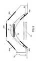
- FIG. 5is a cross-sectional view of a device 500 having multiple energy sources 503 a - c , an object 401 and a pressure conduit 504 , according to one embodiment.
- FIG. 6is a cross-sectional view of a device 600 having multiple energy sources 503 a - c , a pressure conduit 504 , and a skin temperature sensor 601 , according to one embodiment.
- FIG. 7is a cross-sectional view of a device 700 having multiple energy sources 503 a - c , a pressure conduit 504 , a membrane 301 , electrodes 503 d and 503 e , and a skin color sensor 701 , according to one embodiment.
- FIG. 8is an exemplary display 800 on a handheld device according to certain embodiments of the invention.
- FIG. 9is a handheld device 900 with a display element 901 that displays at least one parameter with respect to a treatment of the biological external tissue 302 , according to one embodiment.
- FIG. 10is a cross-sectional view of a device 1000 having multiple energy sources 503 a - 503 e that are not exposed to any pressure, and a pressure conduit 1004 , according to one embodiment.
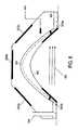
- FIG. 11is a cross-sectional view of a device 1100 having a body that is applied to biological external tissue 302 and multiple vacuum chambers as shown in A and B on FIG. 11 , according to one embodiment.
- FIG. 12is a cross-sectional view of an apparatus 1200 that attaches to an existing device 1201 to apply energy to biological external tissue 302 through energy sources 503 a - c.
- FIG. 13is an electrical schematic of a handheld device according to one exemplary embodiment.
- FIG. 14A-Fare graphical process flows of a device to treat biological external tissue using a liquid and/or other material to cool the biological external tissue before and/or during application of an energy, according to one embodiment.
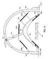
- FIG. 15is a cross-sectional view of a device 1500 having a body that is applied to biological external tissue 302 , the device 1500 having multiple vacuum chambers and a material conduit thru which a material is applied to the biological external tissue, according to one embodiment.
- FIG. 16is an operation flow of reducing pressure of an inner chamber and applying a material to the biological external tissue, according to one embodiment.
- FIG. 17is an operation flow of forming a vacuum seal between a device and a biological external tissue, and applying a material to the biological external tissue within a chamber formed above the biological external tissue, according to one embodiment.
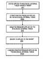
- FIG. 18is an operation flow of coating a liquid on an area of biological external tissue, forming a pressure equal to or lower than a vapor pressure of the liquid, and applying an energy to a target before the blood concentration in the biological external tissue returns to at least a normal state, according to one embodiment.
- FIG. 19is an operation flow of depositing a material on an area of a biological external tissue having a target, applying a device to the area, and bringing the biological external tissue into contact with a protruding object of the device that is above the area.
- FIG. 20is an operation flow of reducing temperature of an area of a biological external tissue having a target by depositing a material on the area, applying a negative pressure to bring the biological external tissue into contact with the device, and applying an energy to the target before the blood concentration in the area returns to at least a normal state, according to one embodiment.
- FIG. 21is a graph illustrating the vaporization pressure in PSI of ethyl alcohol and water as a function of temperature in Celsius, according to one embodiment.
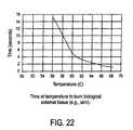
- FIG. 22is a graph illustrating the time in seconds to burn biological external tissue, according to one embodiment.
- FIG. 23is a three-dimensional, cut-away view of a device to treat biological external tissue according to one embodiment.
- FIG. 24is a three-dimensional view of a device having an inner chamber and an outer portion to treat biological external tissue according to one embodiment.
- FIG. 2 ais a process flow diagram showing a method of applying positive pressure and negative pressure to biological external tissue having a target.
- a deviceis applied to biological external tissue having a target.
- the devicemay be, for example, the device 400 shown in FIG. 4 .
- the biological external tissueis dermalogical tissue and the device is applied by pressing the device against such tissue to create a sealed region between the device and such tissue.
- the targetis skin lesions in one embodiment of the invention.
- the targetis melanin, blood, tattoo ink, and/or collagen.
- the targetcan alternatively be any biological external tissue requiring treatment by an energy source.
- a positive pressureis applied to the biological external tissue.
- the positive pressureis applied using an object which protrudes from a surface of a body of the device (such as object 401 ) which surface faces the area to be treated.
- the positive pressureis a gas such as a cooling gas, which is applied to the biological external tissue.
- a negative pressureis applied to the biological external tissue.
- the negative pressureis a vacuum (e.g., a pressure which is less than or substantially less than atmospheric pressure, such as 400 torr).
- energyis applied to the target inside the biological external tissue.
- the energyis incoherent light, coherent light, radio frequency, and/or ultrasound, according to various embodiments of the invention.
- the energy sourcemay be a combination of multiple energies such as a radio frequency and a coherent light in some embodiments of the invention.
- pressurized gasis used to force the blood out of the dermal plexus.
- the positive pressure applied in operation 202 atends to push blood out of the treatment area, thereby reducing the amount of energy absorption by the blood in the treatment area. This pushing of blood normally occurs just before the application of energy to the treatment area.
- FIG. 2 bis a process flow diagram showing a method for applying negative pressure to biological external tissue having a target.
- a devicesuch as, for example, the device 300 shown in FIG. 3
- operation 201 of FIG. 2 bmay be similar to operation 201 of FIG. 2 a .
- operation 203 of FIG. 2 ba negative pressure is applied to the biological external tissue.
- operation 204 of FIG. 2 benergy is applied to the target, which may be energy as described with reference to FIG. 2 a .
- no positive pressureis applied to the biological external tissue prior to the negative pressure being applied.
- FIG. 2 cis a process flow diagram showing a method for applying a sequence of positive pressure, negative pressure, and positive pressure to biological external tissue having a target.
- a devicesuch as, for example, the device 400 shown in FIG. 4
- a first positive pressureis applied to the biological external tissue.
- the positive pressuremay be a cooling gas and/or an object.
- a negative pressureis applied to the biological external tissue; this is similar to operation 203 of FIG. 2 a .
- operation 202 cenergy is applied to the target; this is similar to operation 204 of FIG. 2 a .
- operation 202 da second positive pressure is applied on the biological external tissue.
- This second positive pressuremay be a gas which pushes the device off the biological external tissue, thereby making it easier to release and move the device from the treatment area to the next treatment area.
- the first positive pressure and the second positive pressureoriginate from the same pressure source.
- operation 202 cmay overlap in time with operation 203 or the sequence may be reversed. Normally, the negative pressure is applied while the energy is applied so operations 203 and 204 overlap substantially in time.
- the first positive pressure and the second positive pressureare different positively applied pressures on the biological external tissue.
- the first positive pressureis applied by a mechanical object (e.g., object 401 ) while the second positive pressure is applied by pumping a gas (e.g., air) into the recess between the device and the skin and/or other biological external tissue.
- a gase.g., air
- the number of uses of the deviceis kept track of to determine usage patterns of the device. The energy used in the methods of FIGS.
- 2 a , 2 b , and 2 cmay originate from a source that is not exposed to any negative and/or positive pressure according to at least one embodiment of the invention.
- generating a peripheral vacuum seal to keep the device on the area of biological external tissuecan also be performed and is described further below.
- the energymay be an electrical current that is applied to the area of biological external tissue before the blood concentration in the area returns to a normal state (or higher than normal state), according to some embodiments of the invention.
- measuring color of the biological external tissuecan alternatively be performed in some embodiments of the methods shown in FIGS. 2 a , 2 b and 2 c .
- measuring temperature of the biological external tissuemay also be performed in some embodiments of the methods shown in FIGS. 2 a , 2 b and 2 c .
- the devicemay display at least one measurement of a sensor on the device in some embodiments of the invention. According to one embodiment of the invention, temperature can be measured by monitoring the change in electrical impedance of the treatment volume.
- the devicemay be a handheld device in some embodiments of the invention.
- a power sourcemay provide power to the device and generate the positive pressure and/or negative pressure through a pressure source connected to the device through a cable element.
- the power level (e.g., strength) of the energymay be automatically regulated by a controller.
- the controllermay also perform other functions.
- the controllermay, for example, contain a timer that is monitoring the elapsed time since a positive pressure is applied to the treatment volume, according to one embodiment of the invention.
- the result of a large elapsed timeis a pool of blood that returns to the surface of biological external tissue such as skin. All skin types including type VI assume a more reddish appearance. The presence of this pool of blood significantly impacts the therapy.
- the bloodabsorbs much of the light energy particularly if the energy is in the visible portion of the spectrum. If the target such as a hair follicle, a tattoo, and/or collagen is deeper in the body than the pool of blood, the therapy is unsuccessful as the majority of the treatment energy is absorbed in the pool of blood before reaching the intended target.
- the blood volume in the dermal plexus and dermisis reduced for a period time before it refills the capillaries and other vessels in these regions.
- This period of timeis on the order of 100 msec, but varies from individual to individual.
- the treatmente.g., application of energy
- the therapyis applied to the volume of skin contained inside the device. If photo-therapy is used, an intense light such as from a laser and/or a flash lamp is directed onto the treatment area of the biological external tissue. If rf therapy is used, an electrical voltage is applied to the electrodes and current is passed through the volume of tissue between the electrodes. Once the therapy is completed, the negative pressure is removed and the skin returns to its normal state.
- a controllermay function in the following manner in the case of a device 400 of FIG. 4 .
- This particular device 400may provide a positive pressure whenever it is being moved from one treatment area to another treatment area.
- the devicetypically has a recessed area which faces the skin and which is enclosed by the device and the skin when the device is pressed against the skin.
- the positive pressuree.g., from a gas
- This positive pressurewill cause a pressure buildup when the device is pressed against the skin to create a seal between the device and the skin.
- the positive pressuree.g., a pressure greater than atmospheric pressure
- the controllermay be programmed as built to automatically shut off the positive pressure and begin drawing a vacuum against the skin to lock the device in place over the desired treatment area.
- the controllermay be programmed and/or built to merely stop the positive pressure (e.g., shut off the flow of a gas into the recess which creates the positive pressure) but not start a vacuum until the user of the device switches a vacuum on. This alternative implementation gives the user a chance to adjust the positioning before turning the vacuum on by a command from the user.
- the biological external tissue that is outside of the devicemay be prevented from stretching in some embodiments of the methods shown in FIGS. 2 a , 2 b and 2 c .
- a technique for preventing this stretchingis described below.
- FIG. 3shows, in cross-sectional view, a device 300 having multiple light sources 303 a , 303 b , and 303 c , and a pressure conduit 304 .
- the light sourcesare contained within a housing and/or body which also includes a cover (which is transparent in the case of light sources) and which separates the light sources from any vacuum generated between the skin and the device).
- the coveris disposed between the membrane 301 and the light sources 303 a - 303 c .
- a handle which is coupled to the bodymay also be included so that a user of the device can easily hold and move the device over a patient's skin and/or other biological external tissue.
- Pressure conduit 304generates a negative vacuum through membrane 301 to bring the biological external tissue 302 into the recess and toward the membrane 301 .
- Membrane 301can be used to collect dead skin, according to one embodiment of the invention.
- the membrane 301is coupled to the conduit 304 to receive the suction from a vacuum pump (not shown) which is coupled to the conduit 304 .
- Light sources 303 a , 303 b and 303 c in FIG. 3are connected to an energy source that is not shown on the figure, according to one embodiment of the invention.
- This energy sourceis not exposed to any pressure through the pressure conduit 304 , according to one embodiment of the invention.
- These light sourcesare shielded from any negative (or positive) pressure by the cover which is optically transparent in the case where the energy sources provide visible light. It will be appreciated that the light sources may alternatively be other types of energy sources (e.g., microwave radio frequency energy) which may not require an optically transparent cover.
- the energy applied to biological external tissue 302 through device 300is transferred through light sources 303 a , 303 b and 303 c .
- the light sources 303 a , 303 b , and 303 cmay include, for example, light emitting diode (LED) lasers of different wavelengths, thus providing different energy sources, due to the different wavelengths, in the body of the device.
- Each light sourcee.g., source 303 a and/or 303 b and/or 303 c
- the panelse.g., light source 303 a
- the panelstransmit light directly to the target without any intervening optical fibers and/or waveguides.
- This energy for device 300can be incoherent light, coherent light, and/or alternatively non-visible light and/or electromagnetic radiation in the range of a radio frequency spectrum, and/or ultrasound, according to various embodiments of the invention.
- the energy source for the device 300may be a flash lamp, arc lamp, high frequency electrical energy, rf energy, an LED and/or a Direct Current electrical energy, according to various embodiments of the invention.
- the inventionis not so limited.
- the present inventioncan be multiple combinations of different energies which are provided by energy sources in the body of the device 300 .
- the device 300may also be connected to a pressure source in the device 300 for providing power to the device 300 and generating pressure through a pressure conduit 304 in one embodiment of the invention.
- the device 300may be a handheld device that is connected to the pressure source (through a cable element), where the pressure source and power source is separate from the handheld device.
- a controller on and/or near device 300may control the strength of the energy applied through the light source 303 a , 303 b and/or 303 c .
- a tapered outer wall on the periphery of device 300prevents the biological external tissue 302 that is outside the device 300 from stretching.
- Stretching the skin(1) reduces the concentration of melanin in the epidermis, (2) reduces scattering in both the epidermis and the dermis, and (3) moves the treatment target closer to the surface.
- Vacuumprovides an excellent mechanism for stretching the skin. By sealing on an area of skin, and generating a vacuum, the skin is drawn and stretched much more than can be done manually.
- FIG. 4shows, in cross-sectional view, shows a device 400 having a body which is coupled to a pair of electrodes 403 a and 403 b , and the body supports an object 401 which protrudes into a recess of the body.
- a pressure conduit 404which is coupled to the body, generates a positive and/or negative pressure on biological external tissue 302 .
- the object 401is designed to be brought into contact with biological external tissue 302 either before and/or while a negative pressure through pressure conduit 404 is applied, thereby drawing the skin into the recess and into contact with the object.
- the objectis used for pressing onto the biological external tissue 302 and forcing the blood out of the dermal plexus, according to one embodiment of the invention.
- the object 401may be stationary relative to the body and/or it may move, like a plunger and/or piston, down from the body and toward the skin.
- a stationary objectis simpler and easier to build but will require that the vacuum draw the skin sufficiently into contact with the object.
- the moving objectcan provide more force and the recess can be larger.
- the object 401may be transparent in the optically visible spectrum, thereby allowing light to pass through it in those embodiments (such as, e.g., the device of FIG. 5 ) which include light sources which emit light that must pass through the object to reach the target.
- pressure conduit 404generates a positive pressure that is a gas, which may be a cooling gas.
- a gaswhich may be a cooling gas.
- the gas that is used to apply pressure to the biological external tissue 302 to force the blood out of the dermal plexus and the dermismay also be used to assist in releasing the device 400 from the biological external tissue 302 .
- the cooling gasis applied before applying an electric current 405 through the biological external tissue 302 through electrodes 403 a and 403 b .
- the pressure conduit 404generates a peripheral vacuum seal to hold the device 400 on biological external tissue prior to generating a vacuum in the recess of the body.
- the object 401 that applies pressure to the biological external tissue 302 to force the blood out of the dermal plexus and the dermismay be cooled to a temperature lower than the epidermis, according to one embodiment of the invention.
- the normal epidermisstarts at a temperature between 31 degrees Celsius and 33 degrees Celsius, according to one embodiment of the invention.
- itwill rise in temperature and may reach a temperature at which burning occurs. If the epidermis starts at a temperature lower than normal, it can change in temperature during treatment more than uncooled skin before it reaches a temperature at which burning occurs.
- the gas that is used to apply pressure to the biological external tissue 302 to force the blood out of the dermal plexus and the dermismay be cooled to a temperature lower than the epidermis, according to one embodiment of the invention.
- the benefit of this cooling with pressurized gasis the same as the benefit obtained with a cool object 401 .
- the object 401 that applies pressure to the biological external tissue 302 to force the blood out of the dermal plexus and the dermismay contain an optical coating to control the wavelengths of light that are used in the treatment, according to another embodiment of the invention.
- the object 401 that applies pressure to the skin to force the blood out of the dermal plexus and the dermismay contain an optical coating to control the energy of the light that is used in the treatment.
- DC or AC or capacitance electrical sensors 403 a and 403 bare used to determine if the biological external tissue 302 is properly positioned in the device 400 .
- the device as shown in FIG. 4can include various sensors such as skin color sensors, temperature sensors, and capacitance sensors on the device in some embodiments of the invention. Furthermore, the device shown in FIG. 4 may have a tapered outer wall on the periphery of the device that prevents the biological external tissue 302 that is outside of the device 400 from stretching, similarly to as described with reference to FIG. 3 . Other features from other embodiments described herein may also be added to the device as shown in FIG. 4 .
- the electrodes 403 a and 403 b in FIG. 4can serve two purposes. One purpose is for applying rf treatment energy according to one embodiment of the invention. The second purpose is as an electrical sensor, according to a different embodiment of the invention. An AC or DC voltage is applied to at least two of the electrical sensors in other embodiments of the invention.
- an electrical current 405passes between the two electrodes 403 a and 403 b .
- a sensor within device 400detects the current 405 , it signals a controller within and/or outside device 400 .
- the controllerinterprets this signal to mean that the biological external tissue 302 is properly positioned according to one embodiment of the invention. This can serve as a secondary skin detection system for added safety, according to at least one embodiment of the invention.
- FIG. 5shows in cross-sectional view, a device 500 having multiple energy sources 503 a - c , an object 401 and a pressure conduit 504 .
- the device 500is pressed against the skin, and the skin is drawn into the recess of the body of device 500 as shown in FIG. 5 .
- the device 500generates a positive pressure against the skin (through the object 401 ) followed by a negative pressure (through a vacuum pump coupled through a valve to conduit 504 ), and then again a positive pressure (from an air pump coupled, through a valve, to conduit 504 ) to be applied to biological external tissue 302 through pressure conduit 504 .
- FIG. 5differs from FIG. 3 and FIG. 4 in that the device shown in FIG. 5 can generate both an electric current through electrodes 503 d and 503 e (to either sense the device's contact with the skin and/or to deliver electrical energy as a treatment) and can apply energy through sources 503 a , 503 b and 503 c on device 500 .
- the energy sources 503 a , 503 b , and 503 cmay be similar to the sources 303 a , 303 b , and 303 c .
- the energy through energy sensors 503 a , 503 b and 503 cis not limited to light, according to one embodiment of the invention as shown in FIG. 5 .
- the pressure conduit 504generates at one point in time in a treatment sequence, a positive pressure comprising a gas in an area of the biological external tissue 302 in FIG. 5 .
- the pressure conduit 504can alternatively generate negative pressure at a different time in the sequence by switching a valve which connects the conduit to either an air pump and/or a vacuum pump.
- Other features(such as, e.g., skin color sensors, a display, etc.) from other embodiments described herein may also be implemented on the device as shown in FIG. 5 .
- a high frequency rf electrical current 405enters the body from one electrode 503 d , passes through a layer of biological external tissue 302 and exits the body at a different electrode 503 e .
- FIG. 5shows a potential pathway through the biological external tissue 302 for this current 405 .
- the current 405passes through the body, it tracks a path through the least resistive tissues.
- Bloodis the most conductive biological entity and hence the rf electricity tends to track the blood vessels. This is fine if the target for the rf is the blood, but if the target is the adjacent tissue such as collagen, the presence of the blood can defeat the intended therapy.
- FIG. 6shows in cross-sectional view, a device 600 having multiple energy sources 503 a - c , a pressure conduit 504 , and a skin temperature sensor 601 .
- the skin temperature sensor 601is a capacitance sensor. It may be placed on the membrane 301 rather than within the body of the device. In one alternative embodiment of the device 600 , an object 401 may also be used, as shown with reference to FIG. 4 . Furthermore, other features from other embodiments described herein may be added to the device 600 shown in FIG. 6 .
- the skin temperature sensor 601is used to measure the temperature of the biological external tissue 302 to prevent burning when applying energy through one or more of energy sources 503 a - c to biological external tissue 302 .
- the skin temperature sensor 601is a non-contact skin temperature sensor that monitors the infrared light emitted from the surface of the biological external tissue 302 and translates this into a surface temperature.
- the information from the skin temperature sensor 601is sent to a controller which is within the body of the device 600 in certain embodiments of the invention.
- the controlleris a micro controller and/or microprocessor that interprets the skin temperature, and if the temperature has reached a dangerous level, the micro controller terminates the application of energy in one embodiment of the invention
- the controlleris a software controlled micro controller and/or microprocessor.
- FIG. 7shows in cross-sectional view, a device 700 having multiple energy sources 503 a - c , a pressure conduit 504 , a membrane 301 , electrodes 503 d and 503 e , and a skin color sensor 701 .
- FIG. 7differs from FIG. 6 in that it does not have a skin temperature sensor 601 , but rather has a skin color sensor 701 .
- the skin color sensor 701is used to measure the level of energy that needs to be applied to biological external tissue 302 based upon the color of the skin and corresponding melanin and blood levels within biological external tissue 302 .
- Other features(such as, e.g., an object 401 , etc.) from other embodiments described herein, may be added to the device shown in FIG. 7 .
- the skin color sensor 701consists of a light source and a photodiode. By shining the light source on the surface of the biological external tissue 302 and reading its reflection with the photodiode, the skin color can be determined.
- the light sourcemay be adjacent to the photodiode (as shown), or it may be separated from it. Determining the skin color prior to treatment is important. Even with stretching, dark skin is still more susceptible to burning than lighter skin. Consequently the treatment energy may be adjusted based upon the readings of the skin color sensor. For darker skin, the treatment energy is lowered. For lighter skin, the treatment energy is raised.
- the skin color sensor ( 4 )can also be used to detect the absence of the blood and further detect the refill of the vessels in the dermal plexus and dermis.
- the skin colorPrior to stretching the biological external tissue 302 , such as skin, into the device 700 , the skin color is measured. As the skin is stretched and the blood is removed from the dermal plexus, the reflected light detected by the photo diode increases due to less absorption by the blood. As the dermal plexus refills, the reflected signal decreases due to increase absorption by the blood.
- the skin color detection devicemonitors this change and notifies a control system within and/or outside the device 700 , according to certain embodiments of the invention.
- the second advantage of stretching the skin prior to and during treatment with intense light sourcesis the reduction in scattering.
- the level of scatteringis directly proportional to the concentration and orientation of the intercellular material. Stretching the skin reduces the concentration of these materials in direct proportion to the level of stretching. The corresponding scattering is subsequently reduced as well.
- the third advantageis that the treatment target moves closer to the surface. Stretching the skin reduces its thickness. One can see this by taking a rubber band and measuring its thickness. Then stretch the rubber band and measure its thickness a second time. The rubber band is thinner. The same effect occurs with the outer layers of the skin. The epidermis becomes thinner. The dermal plexus becomes thinner. Even the dermis becomes thinner. The target however, remains in the dermis and is now closer to the surface and thus more energy can reach it.
- FIG. 8shows an exemplary display which may be disposed on a surface of a handheld device, such as any of the devices shown in FIGS. 3-7 and 9 - 11 .
- FIG. 9shows a perspective view of a handheld device 900 with a display on a surface of the device.
- the device of FIG. 9may include the various features described herein, such as multiple energy sources, an object which pushes blood out of the treatment area, one or more pressure conduits, etc.
- the device 900includes a pixilated display with multiple rows and columns of pixels on the display 901 . An example of the content of such a display is shown in FIG.
- FIG. 8which shows a display 800 which indicates the status 801 of the device (e.g., “Standby” or “On” or “Treating”), the power status 802 of the device (e.g., Low or Medium or High along with a bar graph which indicates the power status), the vacuum status 803 of the device (e.g., pneumatic level is “Low” or “High”), the skin's temperature 804 (e.g., 42° C.), the skin's color 805 (e.g., 4) and the patient's pulse count 806 (e.g., 76).
- the status 801 of the devicee.g., “Standby” or “On” or “Treating”
- the power status 802 of the devicee.g., Low or Medium or High along with a bar graph which indicates the power status
- the vacuum status 803 of the devicee.g., pneumatic level is “Low” or “High”
- the skin's temperature 804e.g
- the display 800being on the handheld, is easier for an operator (e.g., physician) to see while doing a treatment because the operator can look at the treatment site while operating the device and still be able to see both the site and the display (rather than having to look at a console which has a display and which is separate from the handheld device.
- the display 901may be a liquid crystal display (LCD) and/or an LED display which is controlled by a display controller which updates the display's pixels to reflect new information.
- the device 900includes a power adjustment control 904 which can be used to control the amount of energy that is applied to the biological external tissue (e.g., to adjusting the intensity of the light from light sources).
- the device 900also includes a pneumatic adjustment control 903 to control the strength of a vacuum that is applied through a vacuum pump (not shown) through the device 900 (e.g., (e.g., a pressure which is less than or substantially less than atmospheric pressure, such as 400 torr).
- a vacuum pumpnot shown
- a pressure which is less than or substantially less than atmospheric pressure, such as 400 torre.g., a pressure which is less than or substantially less than atmospheric pressure, such as 400 torr.
- the device 900includes a cable 905 that delivers power and pressures to operate device 900 (e.g., the cable 905 is connected on the other end to a wall power outlet, and/or a standalone central control station); a vacuum through device 900 to be applied to the biological external tissue in front of the disposable tip 902 (e.g., the vacuum may be delivered through conduit 905 along with power by maintaining a separate chamber that separately carries a negative pressure through device 900 ); a positive pressure to press down on biological external tissue (e.g., carried through a separate chamber than the one that carries the vacuum and power); and the cable 905 may optionally include various electrical wires that deliver signals to and from various sensors (e.g., sensors on the device 900 may include skin temperature sensors, skin color sensors, and capacitance sensors, etc.) on device 900 to a standalone central control station (not shown) in addition to (or rather than) the hand piece display 901 .
- a standalone central control stationnot shown
- the standalone central control stationmay be a computer that has a printer and/or storage device(s) for recording data from the sensors on device 900 .
- the disposable tip 902 on device 900may be a disposable membrane 301 and/or may be custom designed to fit a particular type of biological external tissue or size of biological external tissue (e.g., the disposable tip 902 may be different for large areas of skin verses small areas of skin, and may be shaped differently to treat areas of biological external tissue that is not purely flat because of contours created by skeletal structures and/or because of hair follicles).
- the handle 906 of device 900may be designed to fit a particular size of hand or may have groves to fit a particular hand size in some embodiments.
- the handle 906may be of variable size (e.g., to fit larger and smaller hands, or to reach into areas of biological external tissue that are otherwise difficult to reach).
- the handle 906may be removable from the device 900 head (e.g., the head might be the handpiece display 906 and disposable tip 902 together) in one embodiment to allow a user of device 900 to quickly put on different types of sensors, display 901 variations, and disposable tip elements 902 .
- FIG. 10shows a device 1000 having multiple energy sources 503 a - 503 e that are not exposed to any pressure, and a pressure conduit 1004 .
- FIG. 10differs from FIG. 3 in that the device shown in FIG. 10 includes multiple energy sources such as electrodes 1003 d and 1003 e , while the device shown in FIG. 3 is limited to light based energy only.
- the pressure conduit 1004 in FIG. 10generates a negative pressure.
- FIG. 11shows a device 1100 having a body that is applied to biological external tissue 302 and multiple vacuum chambers shown as A and B on FIG. 11 .
- the device 1100 in FIG. 11applies two vacuum pressures at different times to biological external tissue 302 .
- One pressure Ais generated at the periphery of device 1100 through the pressure conduits 1004 and 1003 .
- a second pressureis generated as shown in B through the pressure conduit 1103 .
- the device 1100includes multiple energy sources 503 a , 503 b , and 503 c and electrodes 503 d and 503 e .
- the membrane 301has two portions: an interior portion 1101 A which generates an interior vacuum in the recess 1106 of the body of device 1100 and a peripheral border portion 1101 B which generates a peripheral vacuum seal between the flat surface of the periphery of the device 1100 and the skin.
- a valve 1107couples the two vacuum chambers together and may be manually controlled by an operator and/or automatically controlled by a micro controller (e.g., micro controller 1303 in the handheld device). Initially, the valve 1107 is set so that a vacuum is generated in only the peripheral border of the device; the peripheral border may be a rectangular frame (resembling a picture frame) or other shapes. This clamps the device to the skin without creating a vacuum in the recess 1106 .
- valve 1107is switched so that a vacuum is generated in both the peripheral border and the recess 1106 of the device.
- the valvemay be positioned at the junction between the portion 1101 A and 1101 B and no separate conduit 1103 is required; in this case the valve is switched open to extend a vacuum from the peripheral border region to the interior region.
- the advantage provided by a device such as device 1100is that the skin within the recess can be stretched even more than skin within devices such as device 300 or 400 because less skin outside of device 1100 will be pulled in by the vacuum within the recess.
- the skin in the peripheral border regionis clamped into a relatively fixed position before the skin within the recess is exposed to a vacuum, which tends to prevent skin from being pulled into device 1100 from outside of the device 1100 .
- One or more features(such as, e.g., an object 401 , skin color sensors, pressure sensors, a display on the handheld, etc.) from other embodiments described herein may be added to the device 1100 according to certain implementations of the invention.
- FIG. 12shows a device that is an apparatus 1200 that attaches to an existing device 1201 to apply energy to biological external tissue 302 through energy sources 503 a - c .
- the apparatus shown in FIG. 12is an embodiment of the invention that is an add-on to existing device 1201 .
- the apparatus 1200adds one or more features as described with reference to FIGS. 1-11 in various embodiments of the invention.
- FIG. 13shows an electric architecture for a handheld device such as device 900 .
- the device 1301 shown in FIG. 13includes an LCD display 1308 having multiple rows and columns of pixels.
- the output of displaymay be the same as or similar to the output of display 800 .
- the display 1308is coupled to a programmable or programmed micro controller 1303 through a display controller 1304 ; it will be appreciated that the display controller 1304 may be eliminated if the micro controller performs the display updating functions of the display controller.
- the micro controller 1303is coupled to sensors 1305 and to energy sources 1307 through a bus 1306 .
- the sensors 1305may be electrical skin contact sensors (such as, e.g., electrodes 503 d and 503 e ), or pressure sensors which detect a pressure above or below atmospheric pressure, and/or skin temperature sensors, and/or skin color sensors and/or a combination of these (and other) sensors.
- the energy sources 1307may be multiple light sources and/or radio frequency electrical electrodes and/or other types of energy sources described herein and/or a combination of these sources.
- the device 1301also includes a cable 1309 , which is similar to cable 905 (attached to handle 906 ) of the device 900 of FIG. 9 .
- the cableprovides power to the handheld from a separate power supply (which may be bulky and thus not practical to hold in a hand), and the cable also provides vacuum and air pressures from a separate (potentially bulky) vacuum pump and air pump.
- the device 900also includes manual controls such as a pneumatic adjustment control 903 (allowing the vacuum to be adjusted) and a power adjustment control 904 (allowing the power of a treatment to be adjusted manually by an operator).
- the device 900also includes a disposable tip 902 which may be a detachable membrane such as membrane 301 which attaches to the treatment face of the body of the device 900 .
- the micro controller 1303may be programmed to operate the device in one or more of the methods described herein.
- the micro controller 1303may receive signals from a skin color sensor 1305 which causes the micro controller 1303 to automatically adjust (without any user input and/or intervention) the power level of the energy sources; the handheld display can then be updated to show that the power level has been changed (and this may be noticed by the operator who can override the changed power setting).
- the skin color sensor(s)may also be used to detect the return of blood pushed away by an object protruding within the recess of the device; upon detecting this change in skin color from signals from the skin color sensor, the micro controller shuts off the power to the energy sources in one embodiment of the invention, and another cycle (e.g., as shown in FIG.
- the micro controller 1303may also receive signals from a skin temperature sensor 1305 which causes the micro controller 1303 to automatically adjust (without any user input and/or intervention) the power level of the energy sources; if, for example, the skin temperature becomes too hot, the micro controller may completely turn off the power to the energy sources in order to protect the patient's skin.
- the micro controller 1303may also receive signals from a pressure sensor which indicates that the device has been presses against the skin at a desired treatment site, thereby creating a seal between the device and the skin; the resulting pressure change (due to this seal) in the recess is detected, and the micro controller begins, automatically, a desired treatment (at either predetermined settings previously entered by an operator and/or automatically based on skin color sensor signals and settings previously entered by an operator).
- the micro controllermay cause an object (e.g., object 401 ) to press against the skin and cause the vacuum to be generated and then apply energy from the energy sources before the blood returns to the treatment.
- Pressing the object against the skin and generating a vacuummay be concurrent (completely overlapped in time) and/or partially overlapping in time and/or sequential with no overlap in time.
- the micro controller 1303may use a timer to determine when the blood returns (to a normal concentration level after having been pushed away) and/or may use signals from a skin color sensor; the timer may be started upon pushing with the protruding object, and the elapsed time may be counted. In this way, the micro controller can assure that the energy is applied in the time period (e.g., 100 m sec) before the blood returns to a normal concentration. If the object which pushes the blood away is moveable, the micro controller may control its movement.
- FIGS. 14A-Fare graphical process flows of a device to treat biological external tissue using a liquid and/or other material to cool the biological external tissue before and/or during application of an energy, according to one embodiment.
- a device 1400 having an inner chamber 1402may be applied to the biological external tissue 302 .
- the pressure within the inner chamber 1402 of the biological external tissueis 1 ATM (e.g., atmospheric pressure) in FIG. 14A .
- a target 1404e.g., a unwanted hair, a wrinkle, a skin blemishes, a tattoo, a vascular and pigmented lesion, etc.
- the target 1404may be eradicated, reduced, and/or treated by the device 1400 .
- a contact cooling of the biological external tissue 302may be performed prior to or after placing the device 1400 on the biological external tissue 302 in FIG. 14A .
- the contact coolingmay be performed by placing a cold, optically transparent element (not shown) on the biological external tissue 302 prior to, during and after treatment (e.g., application of energy as later will be described in FIG. 14E ).
- the optically transparent elementmay cool the area to be treated (e.g., the biological external tissue 302 directly below the inner chamber 1402 ) to a temperature below normal body temperature (e.g. the normal body temperature of a human being, and/or other living being having biological external tissue 302 ).
- the temperature rise of the pre-cooled area of the biological external tissue 302 to a level where the biological external tissue 302 burnsis more than for a non pre-cooled area. For example, if the goal is to always maintain a treated area of the biological external tissue 302 below 60 C, the temperature of the treated area must rise from 33 C to 60 C or 27 C if not pre-cooled. If pre-cooled to 10 C, the area must rise 50 C (e.g., from 10 C to 60 C).
- the optically transparent elementmay remove heat from the treated area of the biological external tissue 302 faster than it is removed without the cooling, thereby providing the biological external tissue 302 with additional protection from the heat caused by the treatment.
- a cryogen spraye.g., a liquid, such as liquid nitrogen, that boils at a temperature below about 110 K ( ⁇ 160° C.) and is used to obtain very low temperatures
- the cryogen spraymay cool an area of biological external tissue 302 to be treated by rapid evaporation of the cryogen. As with the contact cooling, temperature rise of the cryogen pre-cooled area to a level where the biological external tissue 302 burns are greater than for a non pre-cooled area.
- the cooling effect of the cryogen spray during the application of the energyprovides some additional protection because the cryogen pre-cooled area may remove heat from the treated area of the biological external tissue 302 faster than it is removed without the pre-cooling.
- a seal 1406(e.g., a vacuum seal), is formed between the device 1400 and the biological external tissue 302 .
- the seal 1406may be formed within an outer portion 2402 of a device 2400 .
- the sealis generated at the periphery of the device 1100 through the pressure conduits 1004 and 1003 .
- the seal 1406may prevent the device 1400 from shifting above the target 1404 during an application of negative pressure, (as described in FIGS. 2 a , 2 b , and 2 c , and as will be further discussed in FIG. 14D ), and/or shifting during the application of an of an energy (as described in FIGS. 2 a , 2 b , and 2 c , and as will be further discussed in FIG. 14E ).
- a material 1408(e.g., a liquid such as water and/or ethyl alcohol, and/or other solid, liquid and/or gas substance having desired properties), is applied to the biological external tissue 302 .
- the material 1408is applied through a conduit 1502 as shown on the device 1500 in FIG. 15 .
- the material 1408 of FIG. 14Cis effective, (e.g., as a cooling material), at pressures below atmospheric pressure, and is different than the contact cooling embodiment and the cryogen cooling embodiment described in FIG. 14A . As described with reference to FIG. 14A , the contact cooling embodiment and the cryogen cooling embodiment work effectively primarily at atmospheric pressure.
- contact cooling and cryogen spraymay not be effective at pressures below atmospheric pressure (e.g., one atmosphere).
- Materials that provide little evaporative cooling at atmospheric pressuremay provide significant evaporative cooling at pressures less than one atmosphere.
- Waterfor example, provides little evaporative cooling at atmospheric pressure, but “boils” at 60 C in one third of an atmosphere and can provide significant evaporative cooling at one third of an atmosphere. These materials may be the material 1408 that is applied to the biological external tissue in the operation shown in FIG. 14C .
- the material 1408there are other materials, substances, and liquids that could be used effectively for the material 1408 .
- An important criterionis that the material 1408 , at a desired temperature, have a vapor pressure equal to or higher than the pressure inside the device 1400 during treatment, (.e.g., application of energy 1414 as described in FIG. 14E ).
- Many alcoholsmeet this criterion.
- Ethyl alcoholhas a vapor pressure of ⁇ 15 PSI at 57 C. Its heat of vaporization is 854 Joules per gram which is less than water's 2450 Joules per gram. Nevertheless, ethyl alcohol may also provide elevated cooling at 55 C as it carries off excess heat by vaporizing.
- the material 1408is applied prior to treatment.
- the material 1408is applied as a spray, wiped out using a sponge and/or other object and/or in any other suitable manner.
- a negative pressure 1410is applied to the device 1400 .
- the negative pressureis applied through the pressure conduit 1103 .
- the negative pressure 1410may bring a portion of the biological external tissue 302 having the target 1404 upward within the inner chamber 1402 as illustrated in FIG. 14D .
- the negative pressure 1410is applied after following the process described in FIGS. 2 a , 2 b , and 2 c . Illustrated in FIG. 14 D, the negative pressure 1410 may reduce the pressure within the inner chamber 1402 below 1 ATM.
- the reduction of pressure within the inner chamber 1402 as described in FIG. 14Dmay cause the material 1408 to change physical state (e.g., from a liquid to a gas).
- the material 1408 changes from a liquid to a gasit may undergo a process called vaporization 1412 as shown in FIG. 14E .
- the quantity of heat required to change the physical state of the material 1408 from a liquid to a gas through vaporization 1412is called a heat of vaporization.
- the heat of vaporization of wateris 2450 Joules per gram.
- the quantity of heat required to raise one gram of water one degree centigradeis called its specific heat.
- the specific heat of wateris 4.184 Joules/gm. As liquid water is heated, every 4.184 Joules of energy that is applied to every gram of water heats that gram one degree centigrade.
- the “boiling point” of water at atmospheric pressureis 100 degrees Centigrade. At the boiling point, it will require 2450 Joules before its temperature starts to rise above 100 degrees Centigrade. This is 35 times more energy than was needed to heat this one gram of water from 30 C to 100° C. At this time, this one gram of water will no longer be a liquid. It will be a gas.
- the boiling point of wateris 100 degrees Centigrade.
- pressures less than atmospheric pressuree.g., less than one atmosphere
- the “boiling point” of wateris reduced.
- the “boiling point” of wateris 60 C.
- 126 Joules of energyis required to heat one gram of water from 30 Centigrade to 60 Centigrade. The temperature would then stop rising until 2450 Joules is applied to this one gram of water.
- this wateris on the biological external tissue 302 (e.g., skin), it may provide strong protection for the biological external tissue 302 rising above 60 Centigrade. Since it may require several seconds for biological external tissue (e.g., human skin) to burn at 60 C, placing water on the skin in a reduced atmosphere may prevent burning.
- an energy 1414may also be applied to the biological external tissue 302 using the device 1400 .
- the energy 1414is the same energy as described previously in FIGS. 2 a , 2 b , and 2 c in operation 204 .
- the energy 1414may be incoherent light, coherent light, radio frequency, and/or ultrasound, according to various embodiments of the invention.
- the energy 1414may be a combination of multiple energies such as a radio frequency and a coherent light in some embodiments of the invention.
- Applying the energy 1414may destroy and/or alter a targeted chromophore (e.g., a target 1404 ) or other target in the dermis and/or epidermis without injuring and/or burning the surrounding epidermis and dermis (e.g., as shown in FIG. 1 a ) in the biological external tissue 302 .
- a targeted chromophoree.g., a target 1404
- the device 1400may be removed from the biological external tissue 302 by applying a positive pressure 1416 to the biological external tissue 302 using the device 1400 .
- the portion of the biological external tissue 302 having the target 1404(as described in FIG. 14D ) may be pushed outside the inner chamber 1402 by the positive pressure 1416 as illustrated in FIG. 14F .
- the positive pressureis applied through the pressure conduits 1004 and 1003 as described in FIG. 10 .
- the pressure within the inner chamber 1402 of the biological external tissuereturns to 1 ATM in FIG. 14F , from a pressure below 1 ATM in FIGS. 14D and 14E because the device 1400 is lifted from the biological external tissue 302 .
- the seal 1406 between the device 1400 and the biological external tissue 302 as described in FIG. 14Bmay be eliminated in the operation shown in FIG. 14F . It should be noted that the target 1404 may be completely eliminated, (e.g., by the application of the energy 1414 ), by the time the operation as shown in FIG. 14F is performed in one embodiment.
- FIG. 15is a cross-sectional view of a device 1500 having a body that is applied to biological external tissue 302 , the device 1500 having multiple vacuum chambers (conduits 1004 , 1103 , 1003 as previously described in FIG. 11 ) and a material conduit 1502 thru which the material 1408 is applied to the biological external tissue 302 , according to one embodiment.
- the device 1500 in FIG. 15is similar to the device 1100 shown in FIG. 11 , except the device 1500 includes the material conduit 1502 .
- the material 1408is applied through the conduit 1502 as shown on the device 1500 in FIG. 15 .
- the material 1408is water and/or ethyl alcohol.
- FIG. 16is an operation flow of a method of reducing pressure of an inner chamber and applying a material to the biological external tissue, according to one embodiment.
- a devicee.g., the device 2400 as illustrated in FIG. 24 , the device 1400 as illustrated in FIG. 14 , and/or the devices illustrated in FIGS. 3-12 , etc.
- an outer portion 2402e.g., as illustrated in FIG. 24
- an inner chamber 2404as illustrated in FIG. 24
- the biological external tissue 302as illustrated in FIG. 24
- a vacuum seal(e.g., a seal 1406 as described in FIG. 14B ) is formed between the outer portion 2402 and the biological external tissue 302 .
- the pressure of the inner chamber 2404is reduced to a first pressure that is below atmospheric pressure (e.g., as shown in FIG. 14D ) to bring at least some of the biological external tissue 302 into the inner chamber 2404 (e.g., and/or alternatively inner chamber 1402 as illustrated in FIGS. 14A-F ).
- a liquide.g., water and/or other material 1408 as illustrated in FIG. 14C
- an energye.g., the energy 1414 as shown in FIG. 14E
- the liquide.g., material 1408
- the vacuum seale.g., seal 1406 in FIG. 14B
- the devicee.g., the device 2400 of FIG. 24
- the biological external tissue 302is damaged (e.g., burned).
- FIG. 17is another example of an embodiment of the invention.
- a devicee.g., such as cut-away view 2300 in FIG. 23 of the device 1400 in FIG. 14A
- a biological external tissue 302e.g., as illustrated in FIGS. 3-24
- a chambere.g., the inner chamber 1402 as illustrated in FIG. 14A
- a vacuum seale.g., a seal 1406 as illustrated in FIG. 14B
- an outer cut-away 2310e.g., the outer cut-away 2310 in FIG. 23 may be a cross-sectional view of the outer portion 2402 in FIG.
- the pressure of the chambere.g., the inner chamber 1402 as illustrated in FIG. 14A
- a pressure that is below atmospheric pressureto bring at least a portion of the biological external tissue 302 into the chamber.
- a liquide.g., water and/or other material 1408
- the liquidevaporates (e.g., through vaporization 1412 as shown in FIG. 14E and/or through other means).
- an energye.g., the energy 1414 as shown in FIG.
- FIG. 17is applied to the portion of the biological external tissue 302 inside the chamber to eradicate a target (e.g., the target 1404 in FIG. 14A ) within the biological external tissue 302 .
- a targete.g., the target 1404 in FIG. 14A
- FIG. 17may use a different sequence of operations.
- FIG. 18is an operation flow of a method of coating a liquid on an area of biological external tissue, forming a pressure equal to or lower than a vapor pressure of the liquid, and applying an energy to a target before the blood concentration in the biological external tissue returns to at least a normal state, according to one embodiment.
- a devicee.g., a cut-away view 2300 as illustrated in FIG. 23 and/or a device 2400 as illustrated in FIG. 24
- a liquide.g., water and/or other material 1408
- a first positive pressure(e.g., as described in FIG. 2 c in operation 202 c ) is applied on the area.
- a negative pressure(e.g., as described in FIG. 2 c in operation 203 , and as illustrated in FIG. 14D ) is applied on the area to bring the biological external tissue 302 into contact with the device that is above the area.
- a pressureis formed equal to a vapor pressure of the liquid (e.g., to vaporize the liquid as illustrated in vaporization 1412 of FIG. 14E ).
- an energyis applied to the target 1404 before the blood concentration in the area returns to at least a normal state.
- a second positive pressureis applied on the area to allow the device to be released from the area before the biological external tissue 302 is damaged (e.g., as described in FIG. 2 c in operation 202 d and as illustrated in FIG. 14F ). It will be appreciated that other implementations of the method of FIG. 18 may use a different sequence of operations.
- FIG. 19is an exemplary embodiment of a method which includes depositing a material on an area of a biological external tissue having a target, applying a device to the area, and bringing the biological external tissue into contact with a protruding object of the device that is above the area.
- a material 1408(as illustrated in FIG. 14C ) is deposited on an area of biological external tissue 302 having a target 1404 .
- a devicee.g., a device 500 as illustrated in FIG. 5 and/or a device 1400 as illustrated in FIG. 14A-F ) is applied to the area.
- a negative pressureis applied on the area to bring the biological external tissue into contact with a protruding object (e.g., object 401 in FIG. 4 and FIG. 5 ) of the device that is above the area (e.g., as described in FIG. 5 ).
- an energye.g., an energy 1414
- the target 1404is applied before the blood concentration in the area of biological external tissue 302 returns to at least a normal state. It will be appreciated that other implementations of the method of FIG. 11 may use a different sequence of operations.
- FIG. 20is another exemplary embodiment of a method which includes reducing temperature of an area of a biological external tissue having a target by depositing a material on the area, applying a negative pressure to bring the biological external tissue closer to and/or into contact with the device, and applying an energy to the target before the blood concentration in the area returns to at least a normal state, according to one embodiment.
- temperature of an area of biological external tissue 302 having a target 1404is reduced by depositing a material 1408 on the area of biological external tissue 302 .
- a devicee.g., a device 1400 of FIG. 14A-F
- a negative pressuree.g., negative pressure 1410 in FIG.
- an energye.g., an energy 1414
- a positive pressuree.g., positive pressure 1416 in FIG. 14F
- FIG. 20It will be appreciated that other implementations of the method of FIG. 20 may use a different sequence of operations.
- FIG. 21is a graph illustrating the vaporization pressure in PSI of ethyl alcohol and water as a function of temperature in Celsius, according to one embodiment.
- There are two curves illustrated in chart 2100 in FIG. 21one curve 2102 for ethyl alcohol, and another curve 2104 for water.
- the ethyl alcohol curve 2102shows various vaporization pressures as a function of temperature. For example, at a temperature of 60 degrees Celsius, the vaporization pressure of ethyl alcohol is approximately ⁇ 8 PSI. As another example, at a temperature of 60 degrees Celsius, the vaporization pressure for water is slightly below ⁇ 12 PSI.
- FIG. 22is a graph illustrating the time in seconds to burn biological external tissue, according to one embodiment.
- the single curve in FIG. 22illustrates an exponential decline in the number of seconds it takes to burn biological external tissue (e.g., human skin) as temperature increases. For example, at a temperature of 58 degrees Celsius, it takes slightly under 10 seconds to burn skin, whereas at a temperature of 64 degrees Celsius, it takes only 2 seconds to burn skin.
- FIG. 23is a three-dimensional, cut-away view of a device to treat biological external tissue according to one embodiment. Portions of FIG. 23 have been previously described in detail in conjunction with FIG. 17 .
- FIG. 23illustrates a cut-away view 2300 (e.g., the cut-away view 2300 may be a three-dimensional cross-sectional view of a device 2400 as illustrated in FIG. 24 ) having a cavity 2308 and an outer cut-away 2310 for treating the biological external tissue 302 having a target 1404 .
- a cut-away view 2300e.g., the cut-away view 2300 may be a three-dimensional cross-sectional view of a device 2400 as illustrated in FIG. 24 .
- the cut-away view 2300 in FIG. 23also includes a port 2302 , a port 2304 , and port 2306 . While three ports ( 2302 , 2304 , and 2304 ) are illustrated, other embodiments may have any number of ports or no ports at all.
- the ports 2302 and 2306may be used to pressure conduits 1004 and 1003 as illustrated in FIG. 11 to connect to the cut-away view 2300 in one embodiment (e.g., to allow a seal 1406 to be formed as illustrated in FIG. 14D ).
- the port 2304may be used to allow the conduit 1103 (as illustrated in FIG. 11 ) to connect to the cut-away view 2300 in another embodiment (e.g., to allow the negative pressure in FIG.
- the ports 2302 and 2306may form a chamber that is separate and isolated from the chamber above the target 1404 (e.g., the inner chamber 1402 as illustrated in FIG. 14A may be separate and isolated from the chamber that forms the seal 1406 in FIG. 14B ).
- an objecte.g., an object 401 of FIG. 4
- FIG. 23Also illustrated in FIG. 23 is a number of energy panel 2312 .
- Each energy panel 2312may be connected to one or more energy sources (e.g., energy sources 503 a - c as illustrated in FIG. 5 ).
- FIG. 24is a three-dimensional view of a device 2400 having an inner chamber 2404 and an outer portion 2402 to treat biological external tissue 312 according to one embodiment. Portions of FIG. 24 have been previously described in detail in conjunction with FIG. 16 .
- the inner chamber 2404 in FIG. 24may completely cover the target 1404 as illustrated in FIG. 24 .
- the inner chamber 2404may be completely isolated (e.g., isolated pressure wise) from the outer portion 2402 .
- a camera and/or video recording device(not shown) having a lens may be connected to the device 2400 so that a user can view the biological external tissue within the inner chamber 2404 .
- the inner portionmay be manually aligned (e.g., through physical marking of the biological external tissue 302 around the target 1404 , and/or by replacing a removable and adjustable size fitting (not shown) for the inner chamber 2404 prior to application of the device 2400 onto the biological external tissue, etc.).
- Various sensor(s) 2406may be installed on the device 2400 in one embodiment.
- Various sensor(s) 2406may include skin color sensors, temperature sensors, motion sensors, vapor pressure sensors (e.g., to sense negative and/or positive pressure within a chamber), material sensors (e.g., to sense the presence of water or other material within the chamber), temperature sensors, capacitance sensors, and a variety of other types of sensors and/or electronics described in FIGS. 1-13 .
- the device 2400may include a vacuum 2408 that generates a negative pressure within the outer portion 2402 to seal (e.g., the seal 1406 as illustrated in FIG. 14 ) the device 2400 to the biological external tissue 302 .
- the device 2400 in FIG. 24may include one or more energy source(s) 2412 .
- the energy source(s) 2412may deliver energy 1414 as described in FIG. 14E .
- energy source(s) 2412may be energy sources described in FIGS. 3-13 (e.g., energy source 503 a - c as illustrated in FIG. 5 ).
- the device 2400may also include a liquid/negative pressure applicator 2410 to apply liquid/negative pressure to the inner chamber 2404 .
- the liquid/negative pressure applicator 2410applies the material 1408 to the biological external tissue 302 within the inner chamber 2404 .
- the liquid/negative pressure applicator 2410applies a negative pressure to the biological external tissue 302 within the inner chamber 2404 to bring the target 1404 and surrounding biological external tissue 302 into the inner chamber 2404 .
- an electrical architecture for a handheld device as described in FIG. 13can be implemented with one or more semiconductor devices including circuitry such as logic circuitry to perform its various functions as described above, in addition to being implemented in software.
- circuitrysuch as logic circuitry to perform its various functions as described above, in addition to being implemented in software.
- hardware circuitrymay provide speed and performance advantages over software implementations of the device 1301 shown in FIG. 13 .
- software implementationsmay be preferred.
- a semiconductor chipmay implement the functions (e.g., as described in FIGS. 2 thru FIG. 24 ) described within the various embodiments using logic gates, transistors, and hardware logic circuitry associated with implementing the various embodiments disclosed herein.
Landscapes
- Physics & Mathematics (AREA)
- Health & Medical Sciences (AREA)
- Surgery (AREA)
- Optics & Photonics (AREA)
- Life Sciences & Earth Sciences (AREA)
- Engineering & Computer Science (AREA)
- Molecular Biology (AREA)
- Nuclear Medicine, Radiotherapy & Molecular Imaging (AREA)
- Electromagnetism (AREA)
- Biomedical Technology (AREA)
- Heart & Thoracic Surgery (AREA)
- Medical Informatics (AREA)
- Otolaryngology (AREA)
- Animal Behavior & Ethology (AREA)
- General Health & Medical Sciences (AREA)
- Public Health (AREA)
- Veterinary Medicine (AREA)
- Surgical Instruments (AREA)
- Radiation-Therapy Devices (AREA)
Abstract
Description
Claims (28)
Priority Applications (4)
| Application Number | Priority Date | Filing Date | Title |
|---|---|---|---|
| US11/024,340US7842029B2 (en) | 2004-05-07 | 2004-12-27 | Apparatus and method having a cooling material and reduced pressure to treat biological external tissue |
| PCT/US2005/015126WO2005112815A1 (en) | 2004-05-07 | 2005-04-29 | Apparatus having a cooling material and reduced pressure to treat biological external tissue |
| US11/123,599US8571648B2 (en) | 2004-05-07 | 2005-05-06 | Apparatus and method to apply substances to tissue |
| US11/732,232US20070179482A1 (en) | 2004-05-07 | 2007-04-02 | Apparatuses and methods to treat biological external tissue |
Applications Claiming Priority (2)
| Application Number | Priority Date | Filing Date | Title |
|---|---|---|---|
| US10/841,273US20050251117A1 (en) | 2004-05-07 | 2004-05-07 | Apparatus and method for treating biological external tissue |
| US11/024,340US7842029B2 (en) | 2004-05-07 | 2004-12-27 | Apparatus and method having a cooling material and reduced pressure to treat biological external tissue |
Related Parent Applications (1)
| Application Number | Title | Priority Date | Filing Date |
|---|---|---|---|
| US10/841,273Continuation-In-PartUS20050251117A1 (en) | 2004-05-07 | 2004-05-07 | Apparatus and method for treating biological external tissue |
Related Child Applications (2)
| Application Number | Title | Priority Date | Filing Date |
|---|---|---|---|
| US11/123,599Continuation-In-PartUS8571648B2 (en) | 2004-05-07 | 2005-05-06 | Apparatus and method to apply substances to tissue |
| US11/732,232Continuation-In-PartUS20070179482A1 (en) | 2004-05-07 | 2007-04-02 | Apparatuses and methods to treat biological external tissue |
Publications (2)
| Publication Number | Publication Date |
|---|---|
| US20050251118A1 US20050251118A1 (en) | 2005-11-10 |
| US7842029B2true US7842029B2 (en) | 2010-11-30 |
Family
ID=34967847
Family Applications (1)
| Application Number | Title | Priority Date | Filing Date |
|---|---|---|---|
| US11/024,340Expired - Fee RelatedUS7842029B2 (en) | 2004-05-07 | 2004-12-27 | Apparatus and method having a cooling material and reduced pressure to treat biological external tissue |
Country Status (2)
| Country | Link |
|---|---|
| US (1) | US7842029B2 (en) |
| WO (1) | WO2005112815A1 (en) |
Cited By (31)
| Publication number | Priority date | Publication date | Assignee | Title |
|---|---|---|---|---|
| US20080167585A1 (en)* | 2006-11-13 | 2008-07-10 | Roee Khen | Apparatus, tip and method for treating tissue |
| US20080221504A1 (en)* | 2006-11-09 | 2008-09-11 | Joseph Aghion | Apparatus and method for treating tissue |
| US8401668B2 (en) | 2007-04-19 | 2013-03-19 | Miramar Labs, Inc. | Systems and methods for creating an effect using microwave energy to specified tissue |
| US8406894B2 (en) | 2007-12-12 | 2013-03-26 | Miramar Labs, Inc. | Systems, apparatus, methods and procedures for the noninvasive treatment of tissue using microwave energy |
| WO2013072472A1 (en)* | 2011-11-16 | 2013-05-23 | Pantec Biosolutions Ag | Skin contact detecting device for a device to be secured |
| US8469951B2 (en) | 2011-08-01 | 2013-06-25 | Miramar Labs, Inc. | Applicator and tissue interface module for dermatological device |
| US8529560B2 (en) | 2005-03-04 | 2013-09-10 | The Invention Science Fund I, Llc | Hair treatment system |
| US8540701B2 (en) | 2005-03-04 | 2013-09-24 | The Invention Science Fund I, Llc | Hair treatment system |
| US8562657B2 (en) | 2005-03-04 | 2013-10-22 | The Invention Science Fund I, Llc | Photopatterning of skin |
| US8679101B2 (en) | 2005-03-04 | 2014-03-25 | The Invention Science Fund I, Llc | Method and system for temporary hair removal |
| US8688228B2 (en) | 2007-04-19 | 2014-04-01 | Miramar Labs, Inc. | Systems, apparatus, methods and procedures for the noninvasive treatment of tissue using microwave energy |
| US20140277299A1 (en)* | 2013-03-14 | 2014-09-18 | Photomedex, Inc. | Apparatus and methods for targeted ultraviolet phototherapy |
| US8853600B2 (en) | 1997-07-31 | 2014-10-07 | Miramar Labs, Inc. | Method and apparatus for treating subcutaneous histological features |
| USD722383S1 (en) | 2012-05-01 | 2015-02-10 | Carol Cole Company | Skin clearing and toning device |
| US9055958B2 (en) | 2005-06-29 | 2015-06-16 | The Invention Science Fund I, Llc | Hair modification using converging light |
| US9078634B2 (en) | 2011-01-27 | 2015-07-14 | Cryosa, Llc | Apparatus and methods for treatment of obstructive sleep apnea utilizing cryolysis of adipose tissues |
| USD739541S1 (en) | 2014-05-12 | 2015-09-22 | Carol Cole Company | Skin clearing and toning device |
| US9149331B2 (en) | 2007-04-19 | 2015-10-06 | Miramar Labs, Inc. | Methods and apparatus for reducing sweat production |
| US9241763B2 (en) | 2007-04-19 | 2016-01-26 | Miramar Labs, Inc. | Systems, apparatus, methods and procedures for the noninvasive treatment of tissue using microwave energy |
| US20170361123A1 (en)* | 2013-03-15 | 2017-12-21 | Pavel V. Efremkin | Apparatus and Method for Treatment of Foot and Nail Diseases |
| USD854699S1 (en) | 2018-05-15 | 2019-07-23 | Carol Cole Company | Elongated skin toning device |
| US10463429B2 (en) | 2007-04-19 | 2019-11-05 | Miradry, Inc. | Methods, devices, and systems for non-invasive delivery of microwave therapy |
| US10624696B2 (en) | 2007-04-19 | 2020-04-21 | Miradry, Inc. | Systems and methods for creating an effect using microwave energy to specified tissue |
| USD891628S1 (en) | 2015-03-03 | 2020-07-28 | Carol Cole Company | Skin toning device |
| US10779885B2 (en) | 2013-07-24 | 2020-09-22 | Miradry. Inc. | Apparatus and methods for the treatment of tissue using microwave energy |
| USD953553S1 (en) | 2020-02-19 | 2022-05-31 | Carol Cole Company | Skin toning device |
| USD957664S1 (en) | 2020-07-29 | 2022-07-12 | Carol Cole Company | Skin toning device |
| US11534335B2 (en) | 2014-10-01 | 2022-12-27 | Cryosa, Inc. | Apparatus and methods for treatment of obstructive sleep apnea utilizing cryolysis of adipose tissues |
| US20230285222A1 (en)* | 2020-08-10 | 2023-09-14 | Park, Won Hee | Handpiece capable of attaching/detaching vacuum cap and adjusting angle of vacuum cap |
| US11779488B2 (en) | 2019-04-10 | 2023-10-10 | ArktiKus LLC | Cooling and refrigeration based on vacuum-driven water evaporation |
| US12369965B2 (en) | 2021-12-30 | 2025-07-29 | Cryosa, Inc. | Systems and methods for treatment of obstructive sleep apnea |
Families Citing this family (81)
| Publication number | Priority date | Publication date | Assignee | Title |
|---|---|---|---|---|
| US6517532B1 (en) | 1997-05-15 | 2003-02-11 | Palomar Medical Technologies, Inc. | Light energy delivery head |
| US8182473B2 (en) | 1999-01-08 | 2012-05-22 | Palomar Medical Technologies | Cooling system for a photocosmetic device |
| ES2226133T3 (en)* | 1997-05-15 | 2005-03-16 | Palomar Medical Technologies, Inc. | DERMATOLOGICAL TREATMENT DEVICE. |
| ES2245506T3 (en) | 1998-03-12 | 2006-01-01 | Palomar Medical Technologies, Inc. | ELECTROMAGNETIC RADIATION APPLICATION SYSTEM ON SKIN. |
| US7935139B2 (en)* | 2001-12-10 | 2011-05-03 | Candela Corporation | Eye safe dermatological phototherapy |
| US7762965B2 (en)* | 2001-12-10 | 2010-07-27 | Candela Corporation | Method and apparatus for vacuum-assisted light-based treatments of the skin |
| EP1627662B1 (en)* | 2004-06-10 | 2011-03-02 | Candela Corporation | Apparatus for vacuum-assisted light-based treatments of the skin |
| WO2004000098A2 (en) | 2002-06-19 | 2003-12-31 | Palomar Medical Technologies, Inc. | Method and apparatus for treatment of cutaneous and subcutaneous conditions |
| EP2522294A2 (en) | 2002-10-23 | 2012-11-14 | Palomar Medical Technologies, Inc. | Phototreatment device for use with coolants and topical substances |
| US8571648B2 (en)* | 2004-05-07 | 2013-10-29 | Aesthera | Apparatus and method to apply substances to tissue |
| US20050251117A1 (en)* | 2004-05-07 | 2005-11-10 | Anderson Robert S | Apparatus and method for treating biological external tissue |
| US7842029B2 (en) | 2004-05-07 | 2010-11-30 | Aesthera | Apparatus and method having a cooling material and reduced pressure to treat biological external tissue |
| US20070179482A1 (en)* | 2004-05-07 | 2007-08-02 | Anderson Robert S | Apparatuses and methods to treat biological external tissue |
| US7856985B2 (en) | 2005-04-22 | 2010-12-28 | Cynosure, Inc. | Method of treatment body tissue using a non-uniform laser beam |
| US12161880B2 (en)* | 2005-06-24 | 2024-12-10 | Koninklijke Philips N.V. | Device and method for low intensity optical hair growth control |
| WO2007019536A2 (en)* | 2005-08-08 | 2007-02-15 | Palomar Medical Technologies, Inc. | Eye-safe photocosmetic device |
| AU2006279865B8 (en)* | 2005-08-12 | 2013-01-31 | Board Of Regents, The University Of Texas System | Systems, devices, and methods for optically clearing tissue |
| US20070093798A1 (en)* | 2005-08-29 | 2007-04-26 | Reliant Technologies, Inc. | Method and Apparatus for Monitoring and Controlling Thermally Induced Tissue Treatment |
| CN101309631A (en)* | 2005-09-15 | 2008-11-19 | 帕洛玛医疗技术公司 | Skin optical characterization device |
| FI120078B (en)* | 2005-10-31 | 2009-06-30 | Hld Healthy Life Devices Ltd | VIBRATOR |
| US8133191B2 (en)* | 2006-02-16 | 2012-03-13 | Syneron Medical Ltd. | Method and apparatus for treatment of adipose tissue |
| KR100799524B1 (en)* | 2006-02-28 | 2008-01-31 | 전용규 | Applicator of Skin Care Device |
| US9107798B2 (en) | 2006-03-09 | 2015-08-18 | Slender Medical Ltd. | Method and system for lipolysis and body contouring |
| US7828734B2 (en) | 2006-03-09 | 2010-11-09 | Slender Medical Ltd. | Device for ultrasound monitored tissue treatment |
| US20070239316A1 (en)* | 2006-03-29 | 2007-10-11 | Jeff Jelinek | Control system and method for environmental systems |
| WO2007117580A2 (en)* | 2006-04-06 | 2007-10-18 | Palomar Medical Technologies, Inc. | Apparatus and method for skin treatment with compression and decompression |
| KR101039758B1 (en) | 2006-04-28 | 2011-06-09 | 젤티크 애스세틱스, 인코포레이티드. | Cryoprotectants for use with therapeutic devices for improved cooling of subcutaneous lipid-rich cells |
| US7586957B2 (en) | 2006-08-02 | 2009-09-08 | Cynosure, Inc | Picosecond laser apparatus and methods for its operation and use |
| US20080183252A1 (en)* | 2006-09-05 | 2008-07-31 | Roee Khen | Apparatus and method for treating cellulite |
| US20080077201A1 (en) | 2006-09-26 | 2008-03-27 | Juniper Medical, Inc. | Cooling devices with flexible sensors |
| US9132031B2 (en) | 2006-09-26 | 2015-09-15 | Zeltiq Aesthetics, Inc. | Cooling device having a plurality of controllable cooling elements to provide a predetermined cooling profile |
| US8192474B2 (en) | 2006-09-26 | 2012-06-05 | Zeltiq Aesthetics, Inc. | Tissue treatment methods |
| DE102006054468A1 (en)* | 2006-11-18 | 2008-05-29 | Braun Gmbh | Device for removing body hair |
| US20080140164A1 (en)* | 2006-12-06 | 2008-06-12 | Clrs Technology Corporation | Light emitting therapeutic devices and methods |
| US8064570B2 (en)* | 2006-12-20 | 2011-11-22 | Innov-X-Systems, Inc. | Hand-held XRF analyzer |
| US9024764B2 (en)* | 2007-01-25 | 2015-05-05 | Honda Motor Co., Ltd. | Method and apparatus for manipulating driver core temperature to enhance driver alertness |
| US20080188840A1 (en)* | 2007-02-02 | 2008-08-07 | Charles Johnson | Handpiece used for cosmetic or dermatologic treatment |
| US20080287839A1 (en) | 2007-05-18 | 2008-11-20 | Juniper Medical, Inc. | Method of enhanced removal of heat from subcutaneous lipid-rich cells and treatment apparatus having an actuator |
| US20090012434A1 (en)* | 2007-07-03 | 2009-01-08 | Anderson Robert S | Apparatus, method, and system to treat a volume of skin |
| US8523927B2 (en) | 2007-07-13 | 2013-09-03 | Zeltiq Aesthetics, Inc. | System for treating lipid-rich regions |
| WO2009026471A1 (en) | 2007-08-21 | 2009-02-26 | Zeltiq Aesthetics, Inc. | Monitoring the cooling of subcutaneous lipid-rich cells, such as the cooling of adipose tissue |
| US20090069795A1 (en)* | 2007-09-10 | 2009-03-12 | Anderson Robert S | Apparatus and method for selective treatment of tissue |
| US7740651B2 (en)* | 2007-09-28 | 2010-06-22 | Candela Corporation | Vacuum assisted treatment of the skin |
| US20090093864A1 (en)* | 2007-10-08 | 2009-04-09 | Anderson Robert S | Methods and devices for applying energy to tissue |
| US20090177190A1 (en)* | 2007-11-16 | 2009-07-09 | Seung Yoon Lee | Lowering skin melanin appearance with red light radiation and red light radiation kit therefor |
| US8603073B2 (en) | 2008-12-17 | 2013-12-10 | Zeltiq Aesthetics, Inc. | Systems and methods with interrupt/resume capabilities for treating subcutaneous lipid-rich cells |
| CA2760610C (en) | 2009-04-30 | 2017-09-19 | Zeltiq Aesthetics, Inc. | Device, system and method of removing heat from subcutaneous lipid-rich cells |
| US9919168B2 (en) | 2009-07-23 | 2018-03-20 | Palomar Medical Technologies, Inc. | Method for improvement of cellulite appearance |
| CA2787374A1 (en) | 2010-01-25 | 2011-07-28 | Zeltiq Aesthetics, Inc. | Home-use applicators for non-invasively removing heat from subcutaneous lipid-rich cells via phase change coolants, and associated devices, systems and methods |
| US8676338B2 (en) | 2010-07-20 | 2014-03-18 | Zeltiq Aesthetics, Inc. | Combined modality treatment systems, methods and apparatus for body contouring applications |
| US20120109114A1 (en)* | 2010-10-27 | 2012-05-03 | Amir Waldman | Hair removal by photothermolysis |
| US10722395B2 (en) | 2011-01-25 | 2020-07-28 | Zeltiq Aesthetics, Inc. | Devices, application systems and methods with localized heat flux zones for removing heat from subcutaneous lipid-rich cells |
| US9883904B2 (en) | 2011-12-20 | 2018-02-06 | Lumenis Ltd. | Method and apparatus for volumetric specific fractional energy impact |
| EP2839552A4 (en) | 2012-04-18 | 2015-12-30 | Cynosure Inc | PICOSECOND LASER APPARATUS AND METHOD OF PROCESSING TARGET TISSUES USING THE SAME |
| US8702772B2 (en)* | 2012-09-11 | 2014-04-22 | Derma Dream Group Ltd. | Device for dermatological use with a failsafe control |
| US9844460B2 (en) | 2013-03-14 | 2017-12-19 | Zeltiq Aesthetics, Inc. | Treatment systems with fluid mixing systems and fluid-cooled applicators and methods of using the same |
| US9545523B2 (en) | 2013-03-14 | 2017-01-17 | Zeltiq Aesthetics, Inc. | Multi-modality treatment systems, methods and apparatus for altering subcutaneous lipid-rich tissue |
| US10285757B2 (en) | 2013-03-15 | 2019-05-14 | Cynosure, Llc | Picosecond optical radiation systems and methods of use |
| US20150216719A1 (en) | 2014-01-31 | 2015-08-06 | Zeltiq Aesthetics, Inc | Treatment systems and methods for treating cellulite and for providing other treatments |
| US10675176B1 (en) | 2014-03-19 | 2020-06-09 | Zeltiq Aesthetics, Inc. | Treatment systems, devices, and methods for cooling targeted tissue |
| USD777338S1 (en) | 2014-03-20 | 2017-01-24 | Zeltiq Aesthetics, Inc. | Cryotherapy applicator for cooling tissue |
| US10952891B1 (en) | 2014-05-13 | 2021-03-23 | Zeltiq Aesthetics, Inc. | Treatment systems with adjustable gap applicators and methods for cooling tissue |
| EP3182943A4 (en)* | 2014-08-18 | 2018-03-21 | Miramar Labs, Inc. | Apparatus, system and method for treating fat tissue |
| US10935174B2 (en) | 2014-08-19 | 2021-03-02 | Zeltiq Aesthetics, Inc. | Stress relief couplings for cryotherapy apparatuses |
| US10568759B2 (en) | 2014-08-19 | 2020-02-25 | Zeltiq Aesthetics, Inc. | Treatment systems, small volume applicators, and methods for treating submental tissue |
| US11154418B2 (en) | 2015-10-19 | 2021-10-26 | Zeltiq Aesthetics, Inc. | Vascular treatment systems, cooling devices, and methods for cooling vascular structures |
| HK1259174A1 (en) | 2016-01-07 | 2019-11-29 | Zeltiq Aesthetics, Inc. | Temperature-dependent adhesion between applicator and skin during cooling of tissue |
| US10765552B2 (en) | 2016-02-18 | 2020-09-08 | Zeltiq Aesthetics, Inc. | Cooling cup applicators with contoured heads and liner assemblies |
| US11382790B2 (en) | 2016-05-10 | 2022-07-12 | Zeltiq Aesthetics, Inc. | Skin freezing systems for treating acne and skin conditions |
| US10555831B2 (en) | 2016-05-10 | 2020-02-11 | Zeltiq Aesthetics, Inc. | Hydrogel substances and methods of cryotherapy |
| US10682297B2 (en) | 2016-05-10 | 2020-06-16 | Zeltiq Aesthetics, Inc. | Liposomes, emulsions, and methods for cryotherapy |
| US11076879B2 (en) | 2017-04-26 | 2021-08-03 | Zeltiq Aesthetics, Inc. | Shallow surface cryotherapy applicators and related technology |
| IT201700101375A1 (en)* | 2017-09-11 | 2019-03-11 | Maurizio Busoni | Device to stimulate skin regeneration |
| US11400308B2 (en) | 2017-11-21 | 2022-08-02 | Cutera, Inc. | Dermatological picosecond laser treatment systems and methods using optical parametric oscillator |
| WO2019165426A1 (en) | 2018-02-26 | 2019-08-29 | Cynosure, Inc. | Q-switched cavity dumped sub-nanosecond laser |
| US11896841B2 (en)* | 2018-06-08 | 2024-02-13 | Quanta System S.P.A. | Photo-thermal targeted treatment system with integrated pre-conditioning, and automatic triggering of photo-thermal targeted treatment via measurement of skin surface temperature and associated methods |
| WO2020028472A1 (en) | 2018-07-31 | 2020-02-06 | Zeltiq Aesthetics, Inc. | Methods, devices, and systems for improving skin characteristics |
| CN113286555B (en) | 2018-10-22 | 2025-02-07 | 艾库尔粉刺治疗公司 | Deterministic and predictive closed-loop control of dosimetry using skin surface temperature measurements and associated methods |
| US11391634B2 (en) | 2019-02-12 | 2022-07-19 | Accure Acne, Inc. | Temperature sensing apparatus for use with a photo-thermal targeted treatment system and associated methods |
| US10864380B1 (en) | 2020-02-29 | 2020-12-15 | Cutera, Inc. | Systems and methods for controlling therapeutic laser pulse duration |
| US11253720B2 (en) | 2020-02-29 | 2022-02-22 | Cutera, Inc. | Dermatological systems and methods with handpiece for coaxial pulse delivery and temperature sensing |
Citations (86)
| Publication number | Priority date | Publication date | Assignee | Title |
|---|---|---|---|---|
| US3674031A (en) | 1969-03-29 | 1972-07-04 | Linde Ag | Method of and device for cryogenic surgery |
| US3712306A (en) | 1971-11-09 | 1973-01-23 | Brymill Corp | Cryogenic application chamber and method |
| US3794039A (en) | 1969-10-25 | 1974-02-26 | Linde Ag | Apparatus for cryosurgery |
| US3862627A (en) | 1973-08-16 | 1975-01-28 | Sr Wendel J Hans | Suction electrode |
| US4388924A (en) | 1981-05-21 | 1983-06-21 | Weissman Howard R | Method for laser depilation |
| US4562838A (en) | 1981-01-23 | 1986-01-07 | Walker William S | Electrosurgery instrument |
| US4573970A (en) | 1974-11-19 | 1986-03-04 | Wolfgang Wagner | Suction injector |
| WO1986001728A2 (en) | 1984-09-07 | 1986-03-27 | Wolfgang Wagner | Injection device with sensor |
| US4600403A (en) | 1974-11-19 | 1986-07-15 | Wolfgang Wagner | Suction injector II |
| AU5560486A (en) | 1984-09-07 | 1987-10-08 | Wolfgang Wagner | Measuring metabolism during liquid injection |
| US4742235A (en) | 1985-07-18 | 1988-05-03 | Hoshin Kagaku Sangyosho Co., Ltd. | Optical treatment device |
| US5000752A (en) | 1985-12-13 | 1991-03-19 | William J. Hoskin | Treatment apparatus and method |
| US5057104A (en) | 1989-05-30 | 1991-10-15 | Cyrus Chess | Method and apparatus for treating cutaneous vascular lesions |
| US5059192A (en) | 1990-04-24 | 1991-10-22 | Nardo Zaias | Method of hair depilation |
| FR2667247A1 (en) | 1990-09-28 | 1992-04-03 | Verre Quartz | Blowing apparatus for hot air for lymphatic drainage |
| US5171215A (en) | 1991-08-22 | 1992-12-15 | Flanagan Dennis F | Endermic method and apparatus |
| US5226907A (en) | 1991-10-29 | 1993-07-13 | Tankovich Nikolai I | Hair removal device and method |
| US5405368A (en) | 1992-10-20 | 1995-04-11 | Esc Inc. | Method and apparatus for therapeutic electromagnetic treatment |
| US5441498A (en) | 1994-02-16 | 1995-08-15 | Envision Surgical Systems, Inc. | Method of using a multimodality probe with extendable bipolar electrodes |
| US5519534A (en) | 1994-05-25 | 1996-05-21 | The Government Of The United States Of America As Represented By The Secretary Of The Department Of Health And Human Services | Irradiance attachment for an optical fiber to provide a uniform level of illumination across a plane |
| WO1996023447A1 (en) | 1995-02-01 | 1996-08-08 | The General Hospital Corporation | Hair removal using optical pulses |
| US5595568A (en) | 1995-02-01 | 1997-01-21 | The General Hospital Corporation | Permanent hair removal using optical pulses |
| US5626631A (en) | 1992-10-20 | 1997-05-06 | Esc Medical Systems Ltd. | Method and apparatus for therapeutic electromagnetic treatment |
| EP0784997A2 (en) | 1994-03-07 | 1997-07-23 | Koblinger, Gerald, Ing. | Skinregions curing device |
| US5824023A (en) | 1995-10-12 | 1998-10-20 | The General Hospital Corporation | Radiation-delivery device |
| US5853407A (en)* | 1996-03-25 | 1998-12-29 | Luxar Corporation | Method and apparatus for hair removal |
| US5964749A (en) | 1995-09-15 | 1999-10-12 | Esc Medical Systems Ltd. | Method and apparatus for skin rejuvenation and wrinkle smoothing |
| US6048352A (en) | 1996-05-17 | 2000-04-11 | Mercury Diagnostics, Inc. | Disposable element for use in a body fluid sampling device |
| US6071239A (en) | 1997-10-27 | 2000-06-06 | Cribbs; Robert W. | Method and apparatus for lipolytic therapy using ultrasound energy |
| US6162218A (en) | 1997-03-16 | 2000-12-19 | Aesculap-Meditec Gmbh | Method and arrangement for photoablation |
| US6168590B1 (en) | 1997-08-12 | 2001-01-02 | Y-Beam Technologies, Inc. | Method for permanent hair removal |
| US6187001B1 (en)* | 1997-12-31 | 2001-02-13 | Radiancy Inc. | Apparatus and method for removing hair |
| US6273884B1 (en) | 1997-05-15 | 2001-08-14 | Palomar Medical Technologies, Inc. | Method and apparatus for dermatology treatment |
| US6277116B1 (en) | 1994-05-06 | 2001-08-21 | Vidaderm | Systems and methods for shrinking collagen in the dermis |
| US6280438B1 (en) | 1992-10-20 | 2001-08-28 | Esc Medical Systems Ltd. | Method and apparatus for electromagnetic treatment of the skin, including hair depilation |
| US20010025190A1 (en) | 1999-12-30 | 2001-09-27 | Pearl Technology Holdings, Llc | Face-lifting device |
| US6315772B1 (en) | 1993-09-24 | 2001-11-13 | Transmedica International, Inc. | Laser assisted pharmaceutical delivery and fluid removal |
| US20020049483A1 (en)* | 1996-01-05 | 2002-04-25 | Knowlton Edward W. | Fluid delivery apparatus |
| US6387380B1 (en) | 1995-05-05 | 2002-05-14 | Thermage, Inc. | Apparatus for controlled contraction of collagen tissue |
| GB2369057A (en) | 2000-11-18 | 2002-05-22 | Lynton Lasers Ltd | Dermatological treatment apparatus |
| US6438424B1 (en) | 1995-05-05 | 2002-08-20 | Thermage, Inc. | Apparatus for tissue remodeling |
| US6461354B1 (en) | 1995-11-22 | 2002-10-08 | Arthrocare Corporation | Systems for electrosurgical dermatological treatment |
| US6461348B1 (en) | 1999-08-27 | 2002-10-08 | Howard S. Bertan | Photo-thermal epilation apparatus with advanced energy storage arrangement |
| US20020169442A1 (en) | 1997-08-12 | 2002-11-14 | Joseph Neev | Device and a method for treating skin conditions |
| WO2002094116A1 (en) | 2001-05-23 | 2002-11-28 | Palomar Medical Technologies, Inc. | Cooling system for a photocosmetic device |
| US6508813B1 (en)* | 1996-12-02 | 2003-01-21 | Palomar Medical Technologies, Inc. | System for electromagnetic radiation dermatology and head for use therewith |
| US6517532B1 (en) | 1997-05-15 | 2003-02-11 | Palomar Medical Technologies, Inc. | Light energy delivery head |
| GB2378392A (en) | 2001-06-20 | 2003-02-12 | Recuperatio Ltd | Wound irrigation/suction device |
| WO2003049633A1 (en) | 2001-12-10 | 2003-06-19 | Inolase 2002 Ltd. | Method and apparatus for improving safety during exposure to a monochromatic light source |
| US6595934B1 (en) | 2000-01-19 | 2003-07-22 | Medtronic Xomed, Inc. | Methods of skin rejuvenation using high intensity focused ultrasound to form an ablated tissue area containing a plurality of lesions |
| US6605080B1 (en) | 1998-03-27 | 2003-08-12 | The General Hospital Corporation | Method and apparatus for the selective targeting of lipid-rich tissues |
| EP1338263A2 (en) | 2002-02-23 | 2003-08-27 | Hwajin Cosmetics Co., Ltd. | Total skin management system and method using the same |
| US20030167032A1 (en) | 2002-03-01 | 2003-09-04 | Ignon Roger G. | Microdermabrasion fluid application system and method |
| WO2003079916A1 (en) | 2002-03-26 | 2003-10-02 | Syneron Medical Ltd. | Method and system for treating skin with rf |
| WO2004007022A1 (en) | 2002-07-11 | 2004-01-22 | Asah Medico A/S | A handpiece for tissue treatment |
| US20040082940A1 (en)* | 2002-10-22 | 2004-04-29 | Michael Black | Dermatological apparatus and method |
| WO2004037068A2 (en) | 2002-10-22 | 2004-05-06 | Reliant Technologies, Inc. | Method and apparatus for treating skin using patterns of optical energy |
| US6766202B2 (en) | 1999-08-30 | 2004-07-20 | Arthrocare Corp. | Systems and methods for intradermal collagen stimulation |
| US6835184B1 (en) | 1999-09-24 | 2004-12-28 | Becton, Dickinson And Company | Method and device for abrading skin |
| US20050049543A1 (en) | 2002-08-16 | 2005-03-03 | Anderson Robert S. | System and method for treating tissue |
| US20050049583A1 (en) | 2002-05-20 | 2005-03-03 | Scimed Life Systems, Inc. | Systems and methods for RF ablation using jet injection of a conductive fluid |
| WO2005082435A1 (en) | 2004-02-24 | 2005-09-09 | Huntleigh Technology Plc | Tissue treatment device |
| US20050215987A1 (en)* | 2001-12-10 | 2005-09-29 | Michael Slatkine | Method and apparatus for vacuum-assisted light-based treatments of the skin |
| US20050222555A1 (en) | 2004-04-01 | 2005-10-06 | Dieter Manstein | Method and apparatus for dermatological treatment |
| US20050234527A1 (en) | 2001-12-10 | 2005-10-20 | Michael Slatkine | Method and apparatus for improving safety during exposure to a monochromatic light source |
| US20050251117A1 (en) | 2004-05-07 | 2005-11-10 | Anderson Robert S | Apparatus and method for treating biological external tissue |
| US20050251118A1 (en) | 2004-05-07 | 2005-11-10 | Anderson Robert S | Apparatus and method having a cooling material and reduced pressure to treat biological external tissue |
| JP2005334188A (en) | 2004-05-26 | 2005-12-08 | Able Corp | Injured tissue treatment device and pad therefor |
| WO2006012752A1 (en) | 2004-08-06 | 2006-02-09 | John Kennedy | Therapy device and related accessories, compositions, and treatment methods |
| US20060058714A1 (en) | 2004-09-10 | 2006-03-16 | Rhoades Dean L | Oxygenating cosmetic instrument having various numbers of heads |
| WO2006031632A2 (en) | 2004-09-09 | 2006-03-23 | Reliant Technologies, Inc. | Interchangeable tips for medical laser treatments and methods for using same |
| US20060189964A1 (en) | 2004-05-07 | 2006-08-24 | Anderson Robert S | Apparatus and method to apply substances to tissue |
| WO2006093384A1 (en) | 2005-03-02 | 2006-09-08 | Meridian Co., Ltd. | Adipose resolve apparatus for low-power laser |
| US20060253178A1 (en) | 2003-12-10 | 2006-11-09 | Leonardo Masotti | Device and equipment for treating tumors by laser thermotherapy |
| US20060259102A1 (en) | 2001-12-10 | 2006-11-16 | Michael Slatkine | Method and apparatus for vacuum-assisted light-based treatments of the skin |
| US20070010861A1 (en) | 2002-03-15 | 2007-01-11 | Anderson Richard R | Methods and devices for selective disruption of fatty tissue by controlled cooling |
| WO2007015247A2 (en) | 2005-08-04 | 2007-02-08 | Inolase 2002 Ltd. | Method and apparatus for inhibiting pain signals during vacuum-assisted medical treatments of the skin |
| IL150094A (en) | 2002-06-06 | 2007-06-17 | Inolase 2002 Ltd | Method and apparatus for improving safety during exposure to a monochromatic light source |
| US20070142885A1 (en) | 2005-11-29 | 2007-06-21 | Reliant Technologies, Inc. | Method and Apparatus for Micro-Needle Array Electrode Treatment of Tissue |
| US20070179482A1 (en) | 2004-05-07 | 2007-08-02 | Anderson Robert S | Apparatuses and methods to treat biological external tissue |
| US20070185432A1 (en) | 2005-09-19 | 2007-08-09 | Transport Pharmaceuticals, Inc. | Electrokinetic system and method for delivering methotrexate |
| US20080065176A1 (en) | 2006-09-11 | 2008-03-13 | Rainbow Communications, Inc. | Vacuum and negative ions assisted phototheraphy device |
| US20080200910A1 (en) | 2007-02-16 | 2008-08-21 | Myoscience, Inc. | Replaceable and/or Easily Removable Needle Systems for Dermal and Transdermal Cryogenic Remodeling |
| US20090005801A1 (en) | 2007-06-28 | 2009-01-01 | Stephen Bartell Eastman | Methods and apparatus for skin stimulation and subcutaneous tissue therapy |
| IL147009A (en) | 2001-12-10 | 2009-11-18 | Candela Corp | Method and apparatus for improving safety during exposure to a monochromatic light source |
| US7643883B2 (en) | 2005-01-28 | 2010-01-05 | Syneron Medical Ltd. | Device and method for treating skin |
- 2004
- 2004-12-27USUS11/024,340patent/US7842029B2/ennot_activeExpired - Fee Related
- 2005
- 2005-04-29WOPCT/US2005/015126patent/WO2005112815A1/enactiveApplication Filing
Patent Citations (98)
| Publication number | Priority date | Publication date | Assignee | Title |
|---|---|---|---|---|
| US3674031A (en) | 1969-03-29 | 1972-07-04 | Linde Ag | Method of and device for cryogenic surgery |
| US3794039A (en) | 1969-10-25 | 1974-02-26 | Linde Ag | Apparatus for cryosurgery |
| US3712306A (en) | 1971-11-09 | 1973-01-23 | Brymill Corp | Cryogenic application chamber and method |
| US3862627A (en) | 1973-08-16 | 1975-01-28 | Sr Wendel J Hans | Suction electrode |
| US4600403A (en) | 1974-11-19 | 1986-07-15 | Wolfgang Wagner | Suction injector II |
| US4573970A (en) | 1974-11-19 | 1986-03-04 | Wolfgang Wagner | Suction injector |
| US4562838A (en) | 1981-01-23 | 1986-01-07 | Walker William S | Electrosurgery instrument |
| US4388924A (en) | 1981-05-21 | 1983-06-21 | Weissman Howard R | Method for laser depilation |
| WO1986001728A2 (en) | 1984-09-07 | 1986-03-27 | Wolfgang Wagner | Injection device with sensor |
| AU5560486A (en) | 1984-09-07 | 1987-10-08 | Wolfgang Wagner | Measuring metabolism during liquid injection |
| US4742235A (en) | 1985-07-18 | 1988-05-03 | Hoshin Kagaku Sangyosho Co., Ltd. | Optical treatment device |
| US5000752A (en) | 1985-12-13 | 1991-03-19 | William J. Hoskin | Treatment apparatus and method |
| US5057104A (en) | 1989-05-30 | 1991-10-15 | Cyrus Chess | Method and apparatus for treating cutaneous vascular lesions |
| US5059192A (en) | 1990-04-24 | 1991-10-22 | Nardo Zaias | Method of hair depilation |
| FR2667247A1 (en) | 1990-09-28 | 1992-04-03 | Verre Quartz | Blowing apparatus for hot air for lymphatic drainage |
| US5171215A (en) | 1991-08-22 | 1992-12-15 | Flanagan Dennis F | Endermic method and apparatus |
| US5226907A (en) | 1991-10-29 | 1993-07-13 | Tankovich Nikolai I | Hair removal device and method |
| US7108689B2 (en) | 1992-10-20 | 2006-09-19 | Lumenis Ltd | Method and apparatus for electromagnetic treatment of the skin, including hair depilation |
| US6514243B1 (en) | 1992-10-20 | 2003-02-04 | Lumenis Ltd. | Method and apparatus for electromagnetic treatment of the skin, including hair depilation |
| US6280438B1 (en) | 1992-10-20 | 2001-08-28 | Esc Medical Systems Ltd. | Method and apparatus for electromagnetic treatment of the skin, including hair depilation |
| US5626631A (en) | 1992-10-20 | 1997-05-06 | Esc Medical Systems Ltd. | Method and apparatus for therapeutic electromagnetic treatment |
| US5405368A (en) | 1992-10-20 | 1995-04-11 | Esc Inc. | Method and apparatus for therapeutic electromagnetic treatment |
| US6315772B1 (en) | 1993-09-24 | 2001-11-13 | Transmedica International, Inc. | Laser assisted pharmaceutical delivery and fluid removal |
| US5441498A (en) | 1994-02-16 | 1995-08-15 | Envision Surgical Systems, Inc. | Method of using a multimodality probe with extendable bipolar electrodes |
| EP0784997A2 (en) | 1994-03-07 | 1997-07-23 | Koblinger, Gerald, Ing. | Skinregions curing device |
| US6277116B1 (en) | 1994-05-06 | 2001-08-21 | Vidaderm | Systems and methods for shrinking collagen in the dermis |
| US5519534A (en) | 1994-05-25 | 1996-05-21 | The Government Of The United States Of America As Represented By The Secretary Of The Department Of Health And Human Services | Irradiance attachment for an optical fiber to provide a uniform level of illumination across a plane |
| EP0806913A1 (en) | 1995-02-01 | 1997-11-19 | The General Hospital Corporation | Hair removal using optical pulses |
| US5735844A (en) | 1995-02-01 | 1998-04-07 | The General Hospital Corporation | Hair removal using optical pulses |
| WO1996023447A1 (en) | 1995-02-01 | 1996-08-08 | The General Hospital Corporation | Hair removal using optical pulses |
| US5595568A (en) | 1995-02-01 | 1997-01-21 | The General Hospital Corporation | Permanent hair removal using optical pulses |
| US6438424B1 (en) | 1995-05-05 | 2002-08-20 | Thermage, Inc. | Apparatus for tissue remodeling |
| US6387380B1 (en) | 1995-05-05 | 2002-05-14 | Thermage, Inc. | Apparatus for controlled contraction of collagen tissue |
| US6387089B1 (en) | 1995-09-15 | 2002-05-14 | Lumenis Ltd. | Method and apparatus for skin rejuvination and wrinkle smoothing |
| US5964749A (en) | 1995-09-15 | 1999-10-12 | Esc Medical Systems Ltd. | Method and apparatus for skin rejuvenation and wrinkle smoothing |
| US5824023A (en) | 1995-10-12 | 1998-10-20 | The General Hospital Corporation | Radiation-delivery device |
| US6461354B1 (en) | 1995-11-22 | 2002-10-08 | Arthrocare Corporation | Systems for electrosurgical dermatological treatment |
| US6749624B2 (en)* | 1996-01-05 | 2004-06-15 | Edward W. Knowlton | Fluid delivery apparatus |
| US20020049483A1 (en)* | 1996-01-05 | 2002-04-25 | Knowlton Edward W. | Fluid delivery apparatus |
| US5853407A (en)* | 1996-03-25 | 1998-12-29 | Luxar Corporation | Method and apparatus for hair removal |
| US6048352A (en) | 1996-05-17 | 2000-04-11 | Mercury Diagnostics, Inc. | Disposable element for use in a body fluid sampling device |
| US6508813B1 (en)* | 1996-12-02 | 2003-01-21 | Palomar Medical Technologies, Inc. | System for electromagnetic radiation dermatology and head for use therewith |
| US6162218A (en) | 1997-03-16 | 2000-12-19 | Aesculap-Meditec Gmbh | Method and arrangement for photoablation |
| US6511475B1 (en) | 1997-05-15 | 2003-01-28 | The General Hospital Corporation | Heads for dermatology treatment |
| US6517532B1 (en) | 1997-05-15 | 2003-02-11 | Palomar Medical Technologies, Inc. | Light energy delivery head |
| US6273884B1 (en) | 1997-05-15 | 2001-08-14 | Palomar Medical Technologies, Inc. | Method and apparatus for dermatology treatment |
| US6168590B1 (en) | 1997-08-12 | 2001-01-02 | Y-Beam Technologies, Inc. | Method for permanent hair removal |
| US20020169442A1 (en) | 1997-08-12 | 2002-11-14 | Joseph Neev | Device and a method for treating skin conditions |
| US6071239A (en) | 1997-10-27 | 2000-06-06 | Cribbs; Robert W. | Method and apparatus for lipolytic therapy using ultrasound energy |
| US6187001B1 (en)* | 1997-12-31 | 2001-02-13 | Radiancy Inc. | Apparatus and method for removing hair |
| US20030199859A1 (en) | 1998-03-27 | 2003-10-23 | Altshuler Gregory B. | Method and apparatus for the selective targeting of lipid-rich tissues |
| US6605080B1 (en) | 1998-03-27 | 2003-08-12 | The General Hospital Corporation | Method and apparatus for the selective targeting of lipid-rich tissues |
| US6461348B1 (en) | 1999-08-27 | 2002-10-08 | Howard S. Bertan | Photo-thermal epilation apparatus with advanced energy storage arrangement |
| US6766202B2 (en) | 1999-08-30 | 2004-07-20 | Arthrocare Corp. | Systems and methods for intradermal collagen stimulation |
| US6835184B1 (en) | 1999-09-24 | 2004-12-28 | Becton, Dickinson And Company | Method and device for abrading skin |
| US20010025190A1 (en) | 1999-12-30 | 2001-09-27 | Pearl Technology Holdings, Llc | Face-lifting device |
| US6595934B1 (en) | 2000-01-19 | 2003-07-22 | Medtronic Xomed, Inc. | Methods of skin rejuvenation using high intensity focused ultrasound to form an ablated tissue area containing a plurality of lesions |
| GB2369057A (en) | 2000-11-18 | 2002-05-22 | Lynton Lasers Ltd | Dermatological treatment apparatus |
| WO2002094116A1 (en) | 2001-05-23 | 2002-11-28 | Palomar Medical Technologies, Inc. | Cooling system for a photocosmetic device |
| GB2378392A (en) | 2001-06-20 | 2003-02-12 | Recuperatio Ltd | Wound irrigation/suction device |
| IL147009A (en) | 2001-12-10 | 2009-11-18 | Candela Corp | Method and apparatus for improving safety during exposure to a monochromatic light source |
| US20060259102A1 (en) | 2001-12-10 | 2006-11-16 | Michael Slatkine | Method and apparatus for vacuum-assisted light-based treatments of the skin |
| US20050234527A1 (en) | 2001-12-10 | 2005-10-20 | Michael Slatkine | Method and apparatus for improving safety during exposure to a monochromatic light source |
| US20050215987A1 (en)* | 2001-12-10 | 2005-09-29 | Michael Slatkine | Method and apparatus for vacuum-assisted light-based treatments of the skin |
| WO2003049633A1 (en) | 2001-12-10 | 2003-06-19 | Inolase 2002 Ltd. | Method and apparatus for improving safety during exposure to a monochromatic light source |
| EP1338263A2 (en) | 2002-02-23 | 2003-08-27 | Hwajin Cosmetics Co., Ltd. | Total skin management system and method using the same |
| US20030167032A1 (en) | 2002-03-01 | 2003-09-04 | Ignon Roger G. | Microdermabrasion fluid application system and method |
| US20070010861A1 (en) | 2002-03-15 | 2007-01-11 | Anderson Richard R | Methods and devices for selective disruption of fatty tissue by controlled cooling |
| WO2003079916A1 (en) | 2002-03-26 | 2003-10-02 | Syneron Medical Ltd. | Method and system for treating skin with rf |
| US6662054B2 (en) | 2002-03-26 | 2003-12-09 | Syneron Medical Ltd. | Method and system for treating skin |
| WO2003096919A1 (en) | 2002-05-17 | 2003-11-27 | Joseph Neev | A device and a method for treating skin conditions |
| US20050049583A1 (en) | 2002-05-20 | 2005-03-03 | Scimed Life Systems, Inc. | Systems and methods for RF ablation using jet injection of a conductive fluid |
| IL150094A (en) | 2002-06-06 | 2007-06-17 | Inolase 2002 Ltd | Method and apparatus for improving safety during exposure to a monochromatic light source |
| WO2004007022A1 (en) | 2002-07-11 | 2004-01-22 | Asah Medico A/S | A handpiece for tissue treatment |
| US7250047B2 (en) | 2002-08-16 | 2007-07-31 | Lumenis Ltd. | System and method for treating tissue |
| US20050049543A1 (en) | 2002-08-16 | 2005-03-03 | Anderson Robert S. | System and method for treating tissue |
| WO2004037068A2 (en) | 2002-10-22 | 2004-05-06 | Reliant Technologies, Inc. | Method and apparatus for treating skin using patterns of optical energy |
| US20040082940A1 (en)* | 2002-10-22 | 2004-04-29 | Michael Black | Dermatological apparatus and method |
| US20060253178A1 (en) | 2003-12-10 | 2006-11-09 | Leonardo Masotti | Device and equipment for treating tumors by laser thermotherapy |
| WO2005082435A1 (en) | 2004-02-24 | 2005-09-09 | Huntleigh Technology Plc | Tissue treatment device |
| US20050222555A1 (en) | 2004-04-01 | 2005-10-06 | Dieter Manstein | Method and apparatus for dermatological treatment |
| US20050251117A1 (en) | 2004-05-07 | 2005-11-10 | Anderson Robert S | Apparatus and method for treating biological external tissue |
| US20060189964A1 (en) | 2004-05-07 | 2006-08-24 | Anderson Robert S | Apparatus and method to apply substances to tissue |
| US20050251118A1 (en) | 2004-05-07 | 2005-11-10 | Anderson Robert S | Apparatus and method having a cooling material and reduced pressure to treat biological external tissue |
| US20070179482A1 (en) | 2004-05-07 | 2007-08-02 | Anderson Robert S | Apparatuses and methods to treat biological external tissue |
| JP2005334188A (en) | 2004-05-26 | 2005-12-08 | Able Corp | Injured tissue treatment device and pad therefor |
| WO2006012752A1 (en) | 2004-08-06 | 2006-02-09 | John Kennedy | Therapy device and related accessories, compositions, and treatment methods |
| WO2006031632A2 (en) | 2004-09-09 | 2006-03-23 | Reliant Technologies, Inc. | Interchangeable tips for medical laser treatments and methods for using same |
| US20060058714A1 (en) | 2004-09-10 | 2006-03-16 | Rhoades Dean L | Oxygenating cosmetic instrument having various numbers of heads |
| US7643883B2 (en) | 2005-01-28 | 2010-01-05 | Syneron Medical Ltd. | Device and method for treating skin |
| WO2006093384A1 (en) | 2005-03-02 | 2006-09-08 | Meridian Co., Ltd. | Adipose resolve apparatus for low-power laser |
| WO2006122136A2 (en) | 2005-05-06 | 2006-11-16 | Aesthera | Apparatus and method to apply substances to tissue |
| WO2007015247A2 (en) | 2005-08-04 | 2007-02-08 | Inolase 2002 Ltd. | Method and apparatus for inhibiting pain signals during vacuum-assisted medical treatments of the skin |
| US20070185432A1 (en) | 2005-09-19 | 2007-08-09 | Transport Pharmaceuticals, Inc. | Electrokinetic system and method for delivering methotrexate |
| US20070142885A1 (en) | 2005-11-29 | 2007-06-21 | Reliant Technologies, Inc. | Method and Apparatus for Micro-Needle Array Electrode Treatment of Tissue |
| US20080065176A1 (en) | 2006-09-11 | 2008-03-13 | Rainbow Communications, Inc. | Vacuum and negative ions assisted phototheraphy device |
| US20080200910A1 (en) | 2007-02-16 | 2008-08-21 | Myoscience, Inc. | Replaceable and/or Easily Removable Needle Systems for Dermal and Transdermal Cryogenic Remodeling |
| US20090005801A1 (en) | 2007-06-28 | 2009-01-01 | Stephen Bartell Eastman | Methods and apparatus for skin stimulation and subcutaneous tissue therapy |
Non-Patent Citations (18)
| Title |
|---|
| "PCT International Preliminary Report on Patentability", PCT/US2008/004101, mailed Oct. 15, 2009, 9 pages. |
| "PCT International Search Report and Written Opinion", PCT/US2008/004101, (Dec. 3, 2008), 17 pages. |
| "PCT International Search Report and Written Opinion",PCT/US2006/017948, (Nov. 29, 2007), 11 pages. |
| "PCT Invitation to Pay Additional Fees", PCT/US2005/015131, (Aug. 5, 2005), 8 pages. |
| "PCT Invitation to Pay Additional Fees", PCT/US2006/017948, (Jun. 18, 2007), 6 pages. |
| "PCT Invitation to Pay Additional Fees", PCT/US2008/004101, (Aug. 12, 2008), 5 pages. |
| Derwent Publication Ltd, London GB; AN 2005-804121 XP002414902 & JP 2005 334188 A (Eiburu KK) Dec. 8, 2005 Abstract (1 page). |
| Fay, et al. Three Approaches for Estimating The Elastic Modulus of the Tympanic Membrane, Journal of Biomechanics 38 (2005) pp. 1807-1815 (9 pages). |
| Goh, et al. Stress Transfer in Collagen Fibrils Reinforcing Connective Tissues: Effects of Collagen Fibril Slenderness and Relative Stiffness, The Journal of Theoretical Biology, vol. 245 (2007) pp. 305-311 (7 pages). |
| L.L. Polla, et al. "Melanosomes are a primary target of Q-switched ruby laser irradiation in guinea pig skin", Journal of Investigative Dermatology, 89, pp. 281-286, 1987. |
| PCT International Preliminary Report of Patentability and Written Opinion of the International Searching Authority for PCT/US2005/015126, International filing date Apr. 29, 2005, mailing date Nov. 16, 2006, (12 pages). |
| PCT International Preliminary Report of Patentability and Written Opinion of the International Searching Authority for PCT/US2005/015131, International filing date Apr. 29, 2005, mailing date Nov. 16, 2006, (11 pages). |
| PCT International Search Report and PCT Written Opinion for PCT International Appln No. US2005/015126, mailed Jul. 26, 2005 (18 pages). |
| PCT Notification of Transmittal of The International Search Report and The Written Opinion of the International Searching Authority or the Declaration; the PCT International Search Report and Written Opinion for PCT International Appln No. PCT/US2006/017948, mailed Oct. 25, 2007. (19 pages). |
| PCT Search Report and Written Opinion for PCT International Appln No. PCT/US2005/015131, mailed Dec. 20, 2005. (18 pages). |
| PCT Written Opinion of the International Searching Authority for PCT International Appln No. PCT/US2006/017948, mailed May 27, 2008. (13 pages). |
| Sasaki, et al. Stress-Strain Curve and Young's Modulus of a Collagen Molecule as Determined by the X-Ray Diffraction Technique, J. Biomechanix, vol. 29, No. (5 pages). |
| Yang, et al. Micromechanical Bending of Single Collagen Fibrils Using Atomic Force Microscopy, 2007 Wiley Periodicals, Published online Jan. 31, 2007 in Wiley InterScience (www.interscience.wiley.com) DOI: 10.1002/jbm.a.31127, pp. 160-168 (9 pages). |
Cited By (56)
| Publication number | Priority date | Publication date | Assignee | Title |
|---|---|---|---|---|
| US8853600B2 (en) | 1997-07-31 | 2014-10-07 | Miramar Labs, Inc. | Method and apparatus for treating subcutaneous histological features |
| US8562657B2 (en) | 2005-03-04 | 2013-10-22 | The Invention Science Fund I, Llc | Photopatterning of skin |
| US8529560B2 (en) | 2005-03-04 | 2013-09-10 | The Invention Science Fund I, Llc | Hair treatment system |
| US8679101B2 (en) | 2005-03-04 | 2014-03-25 | The Invention Science Fund I, Llc | Method and system for temporary hair removal |
| US8540701B2 (en) | 2005-03-04 | 2013-09-24 | The Invention Science Fund I, Llc | Hair treatment system |
| US9055958B2 (en) | 2005-06-29 | 2015-06-16 | The Invention Science Fund I, Llc | Hair modification using converging light |
| US20080221504A1 (en)* | 2006-11-09 | 2008-09-11 | Joseph Aghion | Apparatus and method for treating tissue |
| US9101524B2 (en)* | 2006-11-09 | 2015-08-11 | Lumenis Ltd. | Apparatus and method for treating tissue |
| US20080167585A1 (en)* | 2006-11-13 | 2008-07-10 | Roee Khen | Apparatus, tip and method for treating tissue |
| US10166072B2 (en) | 2007-04-19 | 2019-01-01 | Miradry, Inc. | Systems and methods for creating an effect using microwave energy to specified tissue |
| US10779887B2 (en) | 2007-04-19 | 2020-09-22 | Miradry, Inc. | Systems and methods for creating an effect using microwave energy to specified tissue |
| US8688228B2 (en) | 2007-04-19 | 2014-04-01 | Miramar Labs, Inc. | Systems, apparatus, methods and procedures for the noninvasive treatment of tissue using microwave energy |
| US10624696B2 (en) | 2007-04-19 | 2020-04-21 | Miradry, Inc. | Systems and methods for creating an effect using microwave energy to specified tissue |
| US12186015B2 (en) | 2007-04-19 | 2025-01-07 | Miradry, Inc. | Methods, devices, and systems for non-invasive delivery of microwave therapy |
| US11419678B2 (en) | 2007-04-19 | 2022-08-23 | Miradry, Inc. | Methods, devices, and systems for non-invasive delivery of microwave therapy |
| US9241763B2 (en) | 2007-04-19 | 2016-01-26 | Miramar Labs, Inc. | Systems, apparatus, methods and procedures for the noninvasive treatment of tissue using microwave energy |
| US10463429B2 (en) | 2007-04-19 | 2019-11-05 | Miradry, Inc. | Methods, devices, and systems for non-invasive delivery of microwave therapy |
| US9427285B2 (en) | 2007-04-19 | 2016-08-30 | Miramar Labs, Inc. | Systems and methods for creating an effect using microwave energy to specified tissue |
| US9149331B2 (en) | 2007-04-19 | 2015-10-06 | Miramar Labs, Inc. | Methods and apparatus for reducing sweat production |
| US8401668B2 (en) | 2007-04-19 | 2013-03-19 | Miramar Labs, Inc. | Systems and methods for creating an effect using microwave energy to specified tissue |
| US8825176B2 (en) | 2007-12-12 | 2014-09-02 | Miramar Labs, Inc. | Apparatus for the noninvasive treatment of tissue using microwave energy |
| US8406894B2 (en) | 2007-12-12 | 2013-03-26 | Miramar Labs, Inc. | Systems, apparatus, methods and procedures for the noninvasive treatment of tissue using microwave energy |
| US9078634B2 (en) | 2011-01-27 | 2015-07-14 | Cryosa, Llc | Apparatus and methods for treatment of obstructive sleep apnea utilizing cryolysis of adipose tissues |
| US11419757B2 (en) | 2011-01-27 | 2022-08-23 | Cryosa, Inc. | Apparatus and methods for treatment of obstructive sleep apnea utilizing cryolysis of adipose tissues |
| US9439805B2 (en) | 2011-01-27 | 2016-09-13 | Cryosa, Llc | Apparatus and methods for treatment of obstructive sleep apnea utilizing cryolysis of adipose tissues |
| US10111774B2 (en) | 2011-01-27 | 2018-10-30 | Cryosa, Inc. | Apparatus and methods for treatment of obstructive sleep apnea utilizing cryolysis of adipose tissues |
| US9028477B2 (en) | 2011-08-01 | 2015-05-12 | Miramar Labs, Inc. | Applicator and tissue interface module for dermatological device |
| US11123136B2 (en) | 2011-08-01 | 2021-09-21 | Miradry, Inc. | Applicator and tissue interface module for dermatological device |
| US9314301B2 (en) | 2011-08-01 | 2016-04-19 | Miramar Labs, Inc. | Applicator and tissue interface module for dermatological device |
| US10321954B2 (en) | 2011-08-01 | 2019-06-18 | Miradry, Inc. | Applicator and tissue interface module for dermatological device |
| US8535302B2 (en) | 2011-08-01 | 2013-09-17 | Miramar Labs, Inc. | Applicator and tissue interface module for dermatological device |
| US8469951B2 (en) | 2011-08-01 | 2013-06-25 | Miramar Labs, Inc. | Applicator and tissue interface module for dermatological device |
| WO2013072472A1 (en)* | 2011-11-16 | 2013-05-23 | Pantec Biosolutions Ag | Skin contact detecting device for a device to be secured |
| USD831835S1 (en) | 2012-05-01 | 2018-10-23 | Carol Cole Company | Skin clearing and toning device |
| USD845496S1 (en) | 2012-05-01 | 2019-04-09 | Carol Cole Company | Skin clearing and toning device |
| USD770635S1 (en) | 2012-05-01 | 2016-11-01 | Carol Cole Company | Skin clearing and toning device |
| USD722383S1 (en) | 2012-05-01 | 2015-02-10 | Carol Cole Company | Skin clearing and toning device |
| US20140277299A1 (en)* | 2013-03-14 | 2014-09-18 | Photomedex, Inc. | Apparatus and methods for targeted ultraviolet phototherapy |
| US10532219B2 (en)* | 2013-03-15 | 2020-01-14 | Pavel V. Efremkin | Apparatus for treatment of wounds and skin medical conditions at a predetermined skin area of a human body |
| US20170361123A1 (en)* | 2013-03-15 | 2017-12-21 | Pavel V. Efremkin | Apparatus and Method for Treatment of Foot and Nail Diseases |
| US10779885B2 (en) | 2013-07-24 | 2020-09-22 | Miradry. Inc. | Apparatus and methods for the treatment of tissue using microwave energy |
| USD739541S1 (en) | 2014-05-12 | 2015-09-22 | Carol Cole Company | Skin clearing and toning device |
| USD756527S1 (en) | 2014-05-12 | 2016-05-17 | Carol Cole Company | Skin clearing and toning device |
| US11534335B2 (en) | 2014-10-01 | 2022-12-27 | Cryosa, Inc. | Apparatus and methods for treatment of obstructive sleep apnea utilizing cryolysis of adipose tissues |
| USD891628S1 (en) | 2015-03-03 | 2020-07-28 | Carol Cole Company | Skin toning device |
| USD1054571S1 (en) | 2015-03-03 | 2024-12-17 | Carol Cole Company | Skin toning device |
| USD959005S1 (en) | 2018-05-15 | 2022-07-26 | Carol Cole Company | Elongated skin toning device |
| USD854699S1 (en) | 2018-05-15 | 2019-07-23 | Carol Cole Company | Elongated skin toning device |
| USD949358S1 (en) | 2018-05-15 | 2022-04-19 | Carol Cole Company | Elongated skin toning device |
| US11779488B2 (en) | 2019-04-10 | 2023-10-10 | ArktiKus LLC | Cooling and refrigeration based on vacuum-driven water evaporation |
| USD953553S1 (en) | 2020-02-19 | 2022-05-31 | Carol Cole Company | Skin toning device |
| USD1047175S1 (en) | 2020-02-19 | 2024-10-15 | Carol Cole Company | Head of a skin toning device |
| USD957664S1 (en) | 2020-07-29 | 2022-07-12 | Carol Cole Company | Skin toning device |
| USD1017822S1 (en) | 2020-07-29 | 2024-03-12 | Carol Cole Company | Skin toning device |
| US20230285222A1 (en)* | 2020-08-10 | 2023-09-14 | Park, Won Hee | Handpiece capable of attaching/detaching vacuum cap and adjusting angle of vacuum cap |
| US12369965B2 (en) | 2021-12-30 | 2025-07-29 | Cryosa, Inc. | Systems and methods for treatment of obstructive sleep apnea |
Also Published As
| Publication number | Publication date |
|---|---|
| US20050251118A1 (en) | 2005-11-10 |
| WO2005112815A1 (en) | 2005-12-01 |
Similar Documents
| Publication | Publication Date | Title |
|---|---|---|
| US7842029B2 (en) | Apparatus and method having a cooling material and reduced pressure to treat biological external tissue | |
| US20070179482A1 (en) | Apparatuses and methods to treat biological external tissue | |
| US20050251117A1 (en) | Apparatus and method for treating biological external tissue | |
| AU2006279865B2 (en) | Systems, devices, and methods for optically clearing tissue | |
| EP1627662B1 (en) | Apparatus for vacuum-assisted light-based treatments of the skin | |
| US5976123A (en) | Heart stabilization | |
| US7762965B2 (en) | Method and apparatus for vacuum-assisted light-based treatments of the skin | |
| Patil | Overview of lasers | |
| CA2195294C (en) | Method and apparatus for depilation using pulsed electromagnetic radiation | |
| US7931028B2 (en) | Skin injury or damage prevention method using optical radiation | |
| US20060004306A1 (en) | Methods and products for producing lattices of EMR-treated islets in tissues, and uses therefor | |
| US20080215039A1 (en) | Method and Apparatus for Inhibiting Pain Signals During Vacuum-Assisted Medical Treatments of the Skin | |
| US20060253176A1 (en) | Dermatological treatment device with deflector optic | |
| AU2006214028A1 (en) | Dermatological treatment device | |
| Altshuler et al. | Lattice of optical islets: a novel treatment modality in photomedicine | |
| Alhallak et al. | The ultimate guide for laser and IPL in the aesthetic field | |
| AU2004266722A1 (en) | Method and apparatus for reducing the appearance of skin markings | |
| JP2005237963A (en) | Method and device for vacuum-aided light-subjected skin therapy | |
| KR101847547B1 (en) | Photopneumatic treatment apparatus for acne and method thereof | |
| Milner et al. | Systems, devices, and methods for optically clearing tissue | |
| Kositratna et al. | Rui Yin |
Legal Events
| Date | Code | Title | Description |
|---|---|---|---|
| AS | Assignment | Owner name:AESTHERA, CALIFORNIA Free format text:ASSIGNMENT OF ASSIGNORS INTEREST;ASSIGNORS:ANDERSON, ROBERT S.;MAOR, ALON;YOUNG, STEVE;REEL/FRAME:016134/0327;SIGNING DATES FROM 20041220 TO 20041221 Owner name:AESTHERA, CALIFORNIA Free format text:ASSIGNMENT OF ASSIGNORS INTEREST;ASSIGNORS:ANDERSON, ROBERT S.;MAOR, ALON;YOUNG, STEVE;SIGNING DATES FROM 20041220 TO 20041221;REEL/FRAME:016134/0327 | |
| FEPP | Fee payment procedure | Free format text:PAYOR NUMBER ASSIGNED (ORIGINAL EVENT CODE: ASPN); ENTITY STATUS OF PATENT OWNER: LARGE ENTITY | |
| AS | Assignment | Owner name:SILICON VALLEY BANK, CALIFORNIA Free format text:SECURITY AGREEMENT;ASSIGNOR:AESTHERA CORPORATION;REEL/FRAME:030294/0003 Effective date:20111031 Owner name:SILICON VALLEY BANK, CALIFORNIA Free format text:SECURITY INTEREST - MEZZANINE LOAN;ASSIGNOR:AESTHERA CORPORATION;REEL/FRAME:030294/0021 Effective date:20120829 | |
| AS | Assignment | Owner name:PARALLEL INVESTMENT OPPORTUNITIES PARTNERS II L.P. Free format text:SHORT-FORM PATENT SECURITY AGREEMENT;ASSIGNOR:AESTHERA CORPORATION;REEL/FRAME:031674/0608 Effective date:20131114 Owner name:CAPITAL ROYALTY PARTNERS II L.P., TEXAS Free format text:SHORT-FORM PATENT SECURITY AGREEMENT;ASSIGNOR:AESTHERA CORPORATION;REEL/FRAME:031674/0608 Effective date:20131114 Owner name:CAPITAL ROYALTY PARTNERS II ? PARALLEL FUND ?A? L. Free format text:SHORT-FORM PATENT SECURITY AGREEMENT;ASSIGNOR:AESTHERA CORPORATION;REEL/FRAME:031674/0608 Effective date:20131114 Owner name:CAPITAL ROYALTY PARTNERS II - PARALLEL FUND "A" L. Free format text:SHORT-FORM PATENT SECURITY AGREEMENT;ASSIGNOR:AESTHERA CORPORATION;REEL/FRAME:031674/0608 Effective date:20131114 | |
| AS | Assignment | Owner name:AESTHERA CORPORATION, CALIFORNIA Free format text:RELEASE OF SECURITY INTEREST IN PATENTS;ASSIGNORS:CAPITAL ROYALTY PARTNERS II L.P.;CAPITAL ROYALTY PARTNERS II - PARALLEL FUND "A" L.P.;PARALLEL INVESTMENTS OPPORTUNITIES PARTNERS II L.P.;REEL/FRAME:032123/0720 Effective date:20140123 Owner name:AESTHERA CORPORATION, CALIFORNIA Free format text:RELEASE OF SECURITY INTEREST IN PATENTS;ASSIGNOR:SILICON VALLEY BANK;REEL/FRAME:032123/0736 Effective date:20140123 | |
| REMI | Maintenance fee reminder mailed | ||
| LAPS | Lapse for failure to pay maintenance fees | ||
| STCH | Information on status: patent discontinuation | Free format text:PATENT EXPIRED DUE TO NONPAYMENT OF MAINTENANCE FEES UNDER 37 CFR 1.362 | |
| FP | Lapsed due to failure to pay maintenance fee | Effective date:20141130 |