US7841845B2 - Open drive scroll machine - Google Patents
Open drive scroll machineDownload PDFInfo
- Publication number
- US7841845B2 US7841845B2US11/130,347US13034705AUS7841845B2US 7841845 B2US7841845 B2US 7841845B2US 13034705 AUS13034705 AUS 13034705AUS 7841845 B2US7841845 B2US 7841845B2
- Authority
- US
- United States
- Prior art keywords
- drive shaft
- input shaft
- housing
- assembly
- gear
- Prior art date
- Legal status (The legal status is an assumption and is not a legal conclusion. Google has not performed a legal analysis and makes no representation as to the accuracy of the status listed.)
- Expired - Fee Related, expires
Links
Images


Classifications
- F—MECHANICAL ENGINEERING; LIGHTING; HEATING; WEAPONS; BLASTING
- F04—POSITIVE - DISPLACEMENT MACHINES FOR LIQUIDS; PUMPS FOR LIQUIDS OR ELASTIC FLUIDS
- F04C—ROTARY-PISTON, OR OSCILLATING-PISTON, POSITIVE-DISPLACEMENT MACHINES FOR LIQUIDS; ROTARY-PISTON, OR OSCILLATING-PISTON, POSITIVE-DISPLACEMENT PUMPS
- F04C18/00—Rotary-piston pumps specially adapted for elastic fluids
- F04C18/02—Rotary-piston pumps specially adapted for elastic fluids of arcuate-engagement type, i.e. with circular translatory movement of co-operating members, each member having the same number of teeth or tooth-equivalents
- F—MECHANICAL ENGINEERING; LIGHTING; HEATING; WEAPONS; BLASTING
- F04—POSITIVE - DISPLACEMENT MACHINES FOR LIQUIDS; PUMPS FOR LIQUIDS OR ELASTIC FLUIDS
- F04C—ROTARY-PISTON, OR OSCILLATING-PISTON, POSITIVE-DISPLACEMENT MACHINES FOR LIQUIDS; ROTARY-PISTON, OR OSCILLATING-PISTON, POSITIVE-DISPLACEMENT PUMPS
- F04C28/00—Control of, monitoring of, or safety arrangements for, pumps or pumping installations specially adapted for elastic fluids
- F04C28/08—Control of, monitoring of, or safety arrangements for, pumps or pumping installations specially adapted for elastic fluids characterised by varying the rotational speed
- F—MECHANICAL ENGINEERING; LIGHTING; HEATING; WEAPONS; BLASTING
- F04—POSITIVE - DISPLACEMENT MACHINES FOR LIQUIDS; PUMPS FOR LIQUIDS OR ELASTIC FLUIDS
- F04C—ROTARY-PISTON, OR OSCILLATING-PISTON, POSITIVE-DISPLACEMENT MACHINES FOR LIQUIDS; ROTARY-PISTON, OR OSCILLATING-PISTON, POSITIVE-DISPLACEMENT PUMPS
- F04C2/00—Rotary-piston machines or pumps
- F04C2/02—Rotary-piston machines or pumps of arcuate-engagement type, i.e. with circular translatory movement of co-operating members, each member having the same number of teeth or tooth-equivalents
- F—MECHANICAL ENGINEERING; LIGHTING; HEATING; WEAPONS; BLASTING
- F04—POSITIVE - DISPLACEMENT MACHINES FOR LIQUIDS; PUMPS FOR LIQUIDS OR ELASTIC FLUIDS
- F04C—ROTARY-PISTON, OR OSCILLATING-PISTON, POSITIVE-DISPLACEMENT MACHINES FOR LIQUIDS; ROTARY-PISTON, OR OSCILLATING-PISTON, POSITIVE-DISPLACEMENT PUMPS
- F04C29/00—Component parts, details or accessories of pumps or pumping installations, not provided for in groups F04C18/00 - F04C28/00
- F04C29/0042—Driving elements, brakes, couplings, transmissions specially adapted for pumps
- F04C29/005—Means for transmitting movement from the prime mover to driven parts of the pump, e.g. clutches, couplings, transmissions
- F—MECHANICAL ENGINEERING; LIGHTING; HEATING; WEAPONS; BLASTING
- F04—POSITIVE - DISPLACEMENT MACHINES FOR LIQUIDS; PUMPS FOR LIQUIDS OR ELASTIC FLUIDS
- F04C—ROTARY-PISTON, OR OSCILLATING-PISTON, POSITIVE-DISPLACEMENT MACHINES FOR LIQUIDS; ROTARY-PISTON, OR OSCILLATING-PISTON, POSITIVE-DISPLACEMENT PUMPS
- F04C18/00—Rotary-piston pumps specially adapted for elastic fluids
- F04C18/02—Rotary-piston pumps specially adapted for elastic fluids of arcuate-engagement type, i.e. with circular translatory movement of co-operating members, each member having the same number of teeth or tooth-equivalents
- F04C18/0207—Rotary-piston pumps specially adapted for elastic fluids of arcuate-engagement type, i.e. with circular translatory movement of co-operating members, each member having the same number of teeth or tooth-equivalents both members having co-operating elements in spiral form
- F04C18/0215—Rotary-piston pumps specially adapted for elastic fluids of arcuate-engagement type, i.e. with circular translatory movement of co-operating members, each member having the same number of teeth or tooth-equivalents both members having co-operating elements in spiral form where only one member is moving
Definitions
- the present inventionrelates to open drive scroll machines. More particularly, the present invention relates to scroll compressors which are exteriorly driven and which incorporate a unique two speed drive system for the open drive scroll machine.
- Scroll type machinesare becoming more and more popular for use as compressors in both refrigeration as well as air conditioning applications due primarily to their capability for extremely efficient operation.
- these machinesincorporate scroll members having a pair of intermeshed spiral wraps, one of which is caused to orbit relative to the other so as to define one or more moving chambers which progressively decrease in size as they travel from an outer suction port toward a center discharge port.
- Some type of power unitis provided which operates to drive the orbiting scroll member via a suitable drive shaft.
- the bottom or lower portion of the housing which contains the scroll membersnormally contains an oil sump for lubrication of the various components of the compressor.
- Scroll machinescan be separated into two categories based upon the power unit which drives the scroll member.
- the first categoryis scroll machines which have the power unit located within the housing along with the scroll members.
- the housing containing the power unit and the scroll memberscan be open to the environment or it can be sealed to provide a hermetic scroll machine wherein the housing also contains the working fluid of the scroll machine.
- the second category of scroll machinesis scroll machines which have the power unit separate from the housing containing the scroll members. These machines are called open drive scroll machines and the housing which contains the scroll members is normally sealed from the environment such that the housing also contains the working fluid of the scroll machine.
- the power unit for these open drive scroll machinescan be provided by a drive belt and a pulley system, a gear drive system, a direct drive system or any other type of drive system.
- the above categories of scroll machinescan each be further subdivided into two additional categories of whether the scroll members are positioned vertically which is most common with the hermetic compressors or whether the scroll members are positioned horizontally which is most common with the open drive type of scroll machines.
- Both the vertical and the horizontal positioned scroll machinesperform satisfactorily in their respective market.
- the power unit for these scroll machinesis a single speed drive or a more expensive variable speed drive system.
- Various applications for scroll machineswould benefit if a scroll machine had a low speed capability and a high speed capability.
- These two speed scroll machinescould be produced at a cost significantly lower than the variable speed scroll machines and thus inexpensively satisfy the market for the applications which would benefit from a scroll machine having a low capacity capability and a high speed capability.
- the present inventiondiscloses a unique two speed drive system for an open drive horizontal scroll machine which functions to operate the scroll machine at a low speed capability when the scroll machine demand is low and a high speed capability when the scroll machine demand is high.
- a unique planetary gear systemis positioned between the power unit and the drive shaft of the scroll machine to provide the two speed capability.
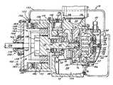
- FIG. 1is a vertical cross-section of an open drive horizontal scroll machine incorporating the unique drive system in accordance with the present invention.
- FIG. 2is a vertical cross-section of an open drive horizontal scroll machine incorporating the unique drive system in accordance with another embodiment of the present invention.
- Compressor 10comprises a compressor body 12 , a cap assembly 14 , a main bearing housing 16 , an oil pump assembly 18 , a lower bearing assembly 20 , an orbiting scroll member 22 , a non-orbiting scroll member 24 and a two speed drive system 26 .
- Compressor body 12is a generally cup shaped member, preferably made from aluminum defining an internal cavity 28 within which is located main bearing housing 16 , an internal bore 30 for mating with oil pump assembly 18 and lower bearing assembly 20 and a suction inlet 32 for mating with the refrigeration circuit associated with compressor 10 .
- Compressor body 12 , cap assembly 14 and lower bearing assembly 20define a sealed chamber 34 within which scroll members 22 and 24 are disposed.
- Cap assembly 14comprises an adapter plate 36 , a partition 38 , a cap 40 , a discharge fitting 42 and a temperature probe 44 .
- Adapter plate 36is secured to compressor body 12 using a plurality of bolts 46 .
- Partition 38is welded about its periphery to adapter plate 36 at the same point that cap 40 is welded to partition 38 .
- Partition 38separates chamber 34 into a suction chamber 48 and a discharge chamber 50 .
- Discharge fitting 42extends through cap 40 and provides a discharge gas outlet from discharge chamber 50 to the refrigeration circuit associated with compressor 10 .
- Temperature probe 44extends through cap 40 and partition 38 such that it is located within a discharge recess 52 located within non-orbiting scroll member 24 .
- a dynamic discharge valve assembly 54is located within discharge recess 52 and is retained within recess 52 by a nut threadingly received within recess 52 .
- Main bearing housing 16is press fit into cavity 28 of compressor body 12 and rests against a shoulder 56 formed by cavity 28 .
- the surface of main bearing housing 16 opposite to shoulder 56is provided with a flat thrust bearing surface 58 against which is located orbiting scroll member 22 which has a usual spiral vane or wrap 60 .
- Projecting opposite to wrap 60is a cylindrical hub 62 having a journal bearing in which is rotatively disposed a drive bushing 66 .
- An Oldham coupling 70is also provided positioned between orbiting scroll member 22 and bearing housing 16 .
- Oldham coupling 70is keyed to orbiting scroll member 22 and non-orbiting scroll member 24 to prevent rotational movement of orbiting scroll member 22 .
- Oldham coupling 70is preferably of the type disclosed in assignee's U.S. Pat. No. 5,320,506, the disclosure of which is hereby incorporated herein by reference.
- Non-orbiting scroll member 24is also provided with a wrap 72 positioned in meshing engagement with wrap 60 of orbiting scroll member 22 .
- Non-orbiting scroll member 24has a centrally disposed passage which communicates with discharge recess 52 through discharge valve assembly 54 which is in turn in communication with discharge chamber 50 defined by cap 40 and partition 38 .
- An annular recess 76is also formed in non-orbiting scroll member 24 within which is disposed a seal assembly 78 .
- Recesses 52 and 76 and seal assembly 78cooperate to define axial pressure biasing chambers which receive pressurized fluid being compressed by wraps 60 and 72 so as to exert an axial biasing force on non-orbiting scroll member 24 to thereby urge the tips of respective wraps 60 and 72 into sealing engagement with the opposed end plate surfaces.
- Seal assembly 78is preferably of the type described in greater detail in U.S. Pat. No. 5,156,539, the disclosure of which is hereby incorporated herein by reference.
- Non-orbiting scroll member 24is designed to be mounted to bearing housing 16 in a suitable manner such as disclosed in U.S. Pat. No. 4,877,382 or U.S. Pat. No. 5,102,316 both disclosures of which are hereby incorporated herein by reference.
- a steel drive shaft or crankshaft 80 having an eccentric crank pin at one end thereofis rotatably journalled in a sleeve bearing 84 in main bearing housing 16 and a roller bearing 86 in lower bearing assembly 20 .
- the crank pinis drivingly disposed within the inner bore of drive bushing 66 .
- the crank pinhas a flat on one surface which drivingly engages a flat surface (not shown) formed in a portion of the bore of drive bushing 66 to provide a radially compliant drive arrangement, such as shown in assignee's aforementioned U.S. Pat. No. 4,877,382.
- Crankshaft 80includes an axially extending bore which intersects with a radial inlet bore and a radial outlet bore.
- the end of crankshaft 80 opposite to the crank pinextends through lower bearing assembly 20 and is adapted to be connected to two speed drives system 26 which is being used to power crank shaft 80 .
- Oil pump assembly 18is disposed within chamber 34 in concentric relationship to drive shaft 80 .
- Oil pump assembly 18comprises a housing, a pump body, a drive member and a plurality of vanes.
- the housingis secured to compressor body 12 using a plurality of bolts.
- the housingdefines an oil inlet passage and an oil outlet passage.
- the pump bodyis secured to the housing using a plurality of bolts and thus the pump body is stationary.
- the pump bodydefines a pumping chamber within which the plurality of vanes are located.
- the drive memberis drivingly secured to the drive shaft 80 such that rotation of drive shaft 80 causes rotation of the drive member.
- Rotation of drive shaft 80causes rotation of the drive member which in turn causes rotation of the plurality or vanes in the pumping chamber and the pumping of oil between the inlet passage which is in communication with a supply passage which extends through compressor body 12 and which is in communication with an oil sump 102 located within sealed chamber 34 through a filter.
- the outlet passageis in communication with a supply passage which extends through compressor body 12 and is in communication with a filter chamber 106 formed by compressor body 12 .
- An oil filter 108is disposed within chamber 106 and chamber 106 is closed by a filter cap 110 which is secure to compressor body 12 using a plurality of bolts. Oil filter 108 is located between the supply passage and a return passage which leads back to oil sump 102 .
- a spring 112biases oil filter 108 away from filter cap 110 to ensure oil flows through filter 108 before entering the return passage.
- the return passageis a stepped diameter passage which restricts oil flow to increase the oil pressure thereby providing oil to the moving components of compressor 10 .
- Lower bearing assembly 20comprises roller bearing 86 and a snap ring 114 .
- Roller bearing 86is disposed between drive shaft 80 and the housing of oil pump assembly 18 and snap ring 114 positions bearing 86 against a shoulder on drive shaft 80 .
- a bearing spacer and a Belville springare positioned between two speed drive system 26 and the outer race of bearing 86 to properly locate bearing 86 .
- Two speed drive system 26comprises a planetary gear set 120 , a clutch assembly 122 and an end cap assembly 124 .
- Planetary gear set 120comprises a sun gear 130 , a plurality of planet gears 132 and a ring gear 134 .
- Sun gear 130is attached to drive shaft 80 .
- the plurality of planet gears 132are meshed with sun gear 130 and are attached to an input shaft 136 .
- Input shaft 136extends through end cap assembly 124 and provides for the driving input to power two speed drive system 26 and thus drive shaft 80 .
- a one-way clutch 138is disposed between input shaft 136 and sun gear 130 .
- One-way clutch 138allows sun gear 130 to rotate faster than input shaft 136 but will provide driving power from input shaft 136 to sun gear 130 when necessary as detailed below.
- Ring gear 134is in mesh with the plurality of planet gears 132 and is rotatably disposed within compressor body 12 .
- Clutch assembly 122comprises a clutch housing 140 , a piston 142 a biasing member on spring 144 and a clutch plate 146 .
- Clutch housing 140is attached to compressor body 12 and is thus prohibited from rotation with respect to compressor body 12 .
- Piston 142 and compressor body 12define a chamber 148 .
- An inlet port 150extends through compressor body 12 to provide communication with chamber 148 .
- a fluid pressure line 152extends between inlet port 150 and discharge chamber 50 .
- a solenoid valve 154controls the flow of pressurized fluid through fluid pressure line 152 .
- solenoid valve 154When low speed operation for two speed drive system 26 of compressor 10 is desired, solenoid valve 154 is activated to place chamber 148 in communication with discharge chamber 50 through pressure line 152 and inlet port 150 . Pressurize fluid within chamber 148 reacts against piston 142 to move piston 142 to the left as shown in FIG. 1 to release ring gear 134 for rotation.
- input powerdrives one member, the second member is driven to provide the output and the third member is fixed. If the third member is not fixed, no power is delivered.
- One-way clutch 138is incorporated to provide low speed operation of two speed drive system 26 .
- solenoid valve 154When solenoid valve 154 is energized and chamber 148 is pressurized, clutch assembly 122 releases ring gear 134 for rotation.
- Sun gear 130is no longer powered by planet gears 132 and thus sun gear 130 will begin to slow down. Sun gear 130 will slow down until one-way clutch 138 engages thus equalizing the speed between input shaft 136 and sun gear 130 resulting in a one-to-one or low speed rotation for two speed drive system 26 .
- pressurized fluid-within chamber 148When it is desired to return to the high speed operation of two-speed drive system 26 , pressurized fluid-within chamber 148 is released into sealed chamber 34 by solenoid valve 154 . The release of pressurized fluid from chamber 148 causes springs 144 to again move piston 142 to the right as shown in FIG. 1 engaging clutch assembly 122 to place two-speed drive system 26 in its high-speed condition.
- Sealed chamber 34is closed by an end cover assembly 160 which comprises a cover plate 162 and a bearing cover 164 .
- Bearing cover 164defines an internal chamber 166 having a plurality of circumferentially spaced radially extending ribs which position a spacer 168 and a plurality of seals 170 between input shaft 136 and bearing cover 164 .
- Input shaft 136extends through bearing cover 164 and is adapted for connection to an external power supply by methods known well in the art.
- FIG. 2an open drive horizontal scroll compressor which incorporates a unique two-speed drive system in accordance with another embodiment of the present invention is illustrated and is designated generally by the reference numeral 210 .
- Compressor 210is the same as compressor 10 except that clutch assembly 122 has been replaced by clutch assembly or solenoid valve assembly 222 .
- Solenoid valve assembly 222comprises a solenoid core 224 , a solenoid coil 226 and clutch plate 146 .
- solenoid coil 226is energized, thus attracting clutch plate 146 and locking it to solenoid core 224 . In this locked position, rotation of ring gear 134 is prohibited. With ring gear 134 locked, power from input shaft 136 is provided to planet gears 132 which results in an increase in speed for sun gear 130 . The increase in speed for sun gear 130 is facilitated by the incorporation of one-way clutch 138 which permits the faster rotation of sun gear 130 . Sun gear 130 is attached to drive shaft 80 for powering compressor 210 . Thus, when solenoid coil 226 is energized, planetary gear set 120 increases the speed between input shaft 136 and drive shaft 80 to provide a high-speed capability for two speed drive system 26 . The amount of speed increase between input shaft 136 and drive shaft 80 will be determined by the diameter of ring gear 134 and the diameter of sun gear 130 .
- solenoid coil 226is de-energized which results in disengaging solenoid core 224 from clutch plate 146 which allows rotation of ring gear 134 .
- input powerdrives one member, the second member is provided to the output and the third member is fixed. If the third member is not fixed, no power is delivered.
- One-way clutch 138is incorporated to provide low speed operation of two speed drive system 26 .
- solenoid coil 226is de-energized, clutch assembly or solenoid valve 222 releases ring gear 134 for rotation.
- Sun gear 130is no longer powered by planet gears 132 and thus, sun gear 130 will begin to slow down. Sun gear 130 will slow down until one-way clutch 138 engages, thus equalizing the speed between input shaft 136 and sun gear 130 resulting in a one-to-one or low speed rotation for two-speed drive-system 26 .
- solenoid coil 226can be energized again to engage clutch plate 146 with solenoid core 224 to plate two-speed drive system 26 in its high-speed condition.
- Two-speed drive system 26 with clutch assembly 122 or solenoid valve assembly 222can be utilized to drive any other type of open-drive positive displacement compressor. While two-speed drive system 26 with clutch assembly 122 on solenoid valve assembly 222 have been illustrated as being located within sealed chamber 34 , it is within the scope of the present invention to mount two-speed drive system 26 external to the compressor or sealed chamber 34 . When mounted externally to the compressor or sealed chamber 34 , two-speed drive system 26 can be packaged together with a drive pulley and the drive pulley clutch.
- two-speed drive system 26is illustrated in use with a horizontal compressor, it can be integrated into a vertical hermetic compressor, if desired.
- two-speed drive system 26is positioned between the motor rotor and the lower bearing.
- the sun gearis attached to the crankshaft, the rotor of the motor has bearings so it can rotate on the compressor shaft with the speed differential being between the crankshaft and the rotor.
- the rotorwould then drive the planetary gear housing assembly.
Landscapes
- Engineering & Computer Science (AREA)
- Mechanical Engineering (AREA)
- General Engineering & Computer Science (AREA)
- Applications Or Details Of Rotary Compressors (AREA)
- Rotary Pumps (AREA)
- Structure Of Transmissions (AREA)
Abstract
Description
Claims (31)
Priority Applications (7)
| Application Number | Priority Date | Filing Date | Title |
|---|---|---|---|
| US11/130,347US7841845B2 (en) | 2005-05-16 | 2005-05-16 | Open drive scroll machine |
| TW094131126ATWI422744B (en) | 2005-05-16 | 2005-09-09 | Open drive scroll machine |
| EP05255573.7AEP1724468A3 (en) | 2005-05-16 | 2005-09-12 | Two speed scroll compressor |
| BRPI0504261-5ABRPI0504261A (en) | 2005-05-16 | 2005-10-03 | open drive rolling machine |
| CN2005101135609ACN1865706B (en) | 2005-05-16 | 2005-10-13 | Open drive scroll machine |
| KR1020050101730AKR101215898B1 (en) | 2005-05-16 | 2005-10-27 | Two speed compressor assembly and open drive scroll machine |
| AU2005234721AAU2005234721A1 (en) | 2005-05-16 | 2005-11-21 | Open drive scroll machine |
Applications Claiming Priority (1)
| Application Number | Priority Date | Filing Date | Title |
|---|---|---|---|
| US11/130,347US7841845B2 (en) | 2005-05-16 | 2005-05-16 | Open drive scroll machine |
Publications (2)
| Publication Number | Publication Date |
|---|---|
| US20060257273A1 US20060257273A1 (en) | 2006-11-16 |
| US7841845B2true US7841845B2 (en) | 2010-11-30 |
Family
ID=36754238
Family Applications (1)
| Application Number | Title | Priority Date | Filing Date |
|---|---|---|---|
| US11/130,347Expired - Fee RelatedUS7841845B2 (en) | 2005-05-16 | 2005-05-16 | Open drive scroll machine |
Country Status (7)
| Country | Link |
|---|---|
| US (1) | US7841845B2 (en) |
| EP (1) | EP1724468A3 (en) |
| KR (1) | KR101215898B1 (en) |
| CN (1) | CN1865706B (en) |
| AU (1) | AU2005234721A1 (en) |
| BR (1) | BRPI0504261A (en) |
| TW (1) | TWI422744B (en) |
Cited By (5)
| Publication number | Priority date | Publication date | Assignee | Title |
|---|---|---|---|---|
| US20070033801A1 (en)* | 2005-08-11 | 2007-02-15 | Mitsubishi Electric Corporation | Method and system for component positioning during assembly of scroll-type fluid machine |
| US20110243766A1 (en)* | 2010-03-31 | 2011-10-06 | Kabushiki Kaisha Toyota Jidoshokki | Compressor with transmission |
| US20130251569A1 (en)* | 2012-03-23 | 2013-09-26 | Bitzer Kuhlmaschinenbau Gmbh | Crankshaft With Aligned Drive and Counterweight Locating Features |
| US11118514B2 (en)* | 2019-08-09 | 2021-09-14 | Hamilton Sundstrand Corporation | Turbomachine dual spool transmission systems |
| US11713720B2 (en) | 2019-08-09 | 2023-08-01 | Hamilton Sundstrand Corporation | Turbomachine dual spool transmission systems |
Families Citing this family (5)
| Publication number | Priority date | Publication date | Assignee | Title |
|---|---|---|---|---|
| FR2916813B1 (en)* | 2007-05-29 | 2013-02-08 | Danfoss Commercial Compressors | SPIRAL REFRIGERATOR COMPRESSOR WITH VARIABLE SPEED |
| CN104949393A (en)* | 2015-07-16 | 2015-09-30 | 上海威乐汽车空调器有限公司 | Scroll compressor for heat pump system |
| CN107842501A (en)* | 2016-09-21 | 2018-03-27 | 比亚迪股份有限公司 | Compressor |
| JP2018100626A (en)* | 2016-12-20 | 2018-06-28 | 三菱重工サーマルシステムズ株式会社 | Hermetic electric compressor, and refrigeration cycle with the same |
| CN116677602A (en)* | 2023-07-26 | 2023-09-01 | 桂林电子科技大学 | A scroll air suspension compressor |
Citations (139)
| Publication number | Priority date | Publication date | Assignee | Title |
|---|---|---|---|---|
| US1738645A (en)* | 1918-08-17 | 1929-12-10 | Sullivan Machinery Co | Rotary fluid-pressure motor |
| US2059830A (en) | 1935-09-05 | 1936-11-03 | Gen Electric | Variable speed dual drive |
| US2669098A (en) | 1950-01-03 | 1954-02-16 | Charles J Buell | Refrigerating system for trucks |
| US2725825A (en) | 1954-03-05 | 1955-12-06 | Yeomans Brothers Co | Liquid handling system |
| US2925723A (en) | 1955-03-31 | 1960-02-23 | Union Stock Yard & Transit Co Chicago | Turbo-refrigeration device |
| US2992769A (en)* | 1957-03-20 | 1961-07-18 | Petty Lab Inc | Rotary fluid compressors |
| US3141310A (en) | 1961-05-03 | 1964-07-21 | Douglas Aircraft Co Inc | Heat pumps |
| US3211365A (en) | 1961-10-16 | 1965-10-12 | Copeland Refrigeration Corp | Compressor structure |
| US3213640A (en) | 1963-03-27 | 1965-10-26 | Dubinsky Moisei Grigorievich | Air turbocompressor refrigeration systems |
| US3279683A (en) | 1964-09-21 | 1966-10-18 | American Motors Corp | Motor-compressor unit |
| US3285504A (en) | 1964-12-10 | 1966-11-15 | Gen Motors Corp | Refrigerant apparatus |
| US3494145A (en) | 1968-06-10 | 1970-02-10 | Worthington Corp | Integral turbo compressor-expander system for refrigeration |
| US3908396A (en) | 1973-06-20 | 1975-09-30 | Carter James B Ltd | Direct cycle heating, cooling and refrigerating apparatus |
| US3924977A (en) | 1973-06-11 | 1975-12-09 | Little Inc A | Positive fluid displacement apparatus |
| US4015438A (en) | 1975-08-29 | 1977-04-05 | The Garrett Corporation | Air cycle air conditioning system for vehicles |
| US4137021A (en) | 1976-02-19 | 1979-01-30 | Lassota Marek J | Rotary compressor and process of compressing compressible fluids |
| US4137006A (en) | 1977-01-26 | 1979-01-30 | K B Southern, Inc. | Composite horizontally split casing |
| US4206596A (en)* | 1978-09-14 | 1980-06-10 | General Motors Corporation | Dual shaft gasifier spool for two shaft gas turbine engine |
| US4260402A (en) | 1979-05-17 | 1981-04-07 | Ingersoll-Rand Company | Housing means for defining air/oil separator and oil reservoir assembly |
| US4293281A (en) | 1979-04-13 | 1981-10-06 | Lamoreaux Charles L | Mobile air charging system |
| US4305192A (en) | 1978-09-27 | 1981-12-15 | Becker John H | Method of fabricating a composite horizontally split casing |
| US4325683A (en) | 1978-10-30 | 1982-04-20 | Sankyo Electric Company Limited | Scroll-type compressor with rotation prevention and anti-deflection means |
| US4340339A (en) | 1979-02-17 | 1982-07-20 | Sankyo Electric Company Limited | Scroll type compressor with oil passageways through the housing |
| US4431356A (en) | 1974-11-14 | 1984-02-14 | Lassota Marek J | Hermetic refrigeration rotary motor-compressor |
| US4468181A (en) | 1981-03-09 | 1984-08-28 | Sanden Corporation | Improved rotation preventing device for a scroll-type fluid displacement apparatus |
| US4527963A (en) | 1982-09-30 | 1985-07-09 | Sanden Corporation | Scroll type compressor with lubricating system |
| US4547138A (en) | 1983-03-15 | 1985-10-15 | Sanden Corporation | Lubricating mechanism for scroll-type fluid displacement apparatus |
| US4551065A (en) | 1982-12-13 | 1985-11-05 | Becker John H | Composite horizontally or vertically split casing with variable casing ends |
| US4551081A (en) | 1981-10-12 | 1985-11-05 | Sanden Corporation | Pulley mechanism for fluid displacement apparatus |
| US4575319A (en) | 1984-08-01 | 1986-03-11 | Sanden Corporation | Method and apparatus for adjusting the angular relationship of spiral elements in a scroll type fluid displacement apparatus |
| US4648814A (en) | 1984-05-25 | 1987-03-10 | Hitachi, Ltd. | Scroll fluid machine with oil injection part and oil relieving passage |
| US4800782A (en)* | 1985-12-17 | 1989-01-31 | G.E. Machine Tool Limited | Accessory transmission |
| US4824345A (en) | 1986-04-28 | 1989-04-25 | Sanden Corporation | Scroll member for scroll type fluid displacement apparatus |
| US4900238A (en) | 1987-03-20 | 1990-02-13 | Sanden Corporation | Scroll type compressor with releasably secured hermetic housing |
| US4913635A (en) | 1987-04-04 | 1990-04-03 | Sanden Corporation | Scroll type compressor with sealing structure for fixed scroll end plate |
| US4922781A (en)* | 1985-08-24 | 1990-05-08 | Shen Peiji | Cycloidal equidistant curved gear transmission mechanism and its device |
| US5052096A (en) | 1988-09-23 | 1991-10-01 | Carrier Corporation | Grommet insertion method and apparatus |
| US5098265A (en) | 1989-04-20 | 1992-03-24 | Hitachi, Ltd. | Oil-free scroll fluid machine with projecting orbiting bearing boss |
| US5110268A (en) | 1989-12-04 | 1992-05-05 | Hitachi, Ltd. | Lubricant supply system of a scroll fluid machine |
| US5137437A (en) | 1990-01-08 | 1992-08-11 | Hitachi, Ltd. | Scroll compressor with improved bearing |
| US5172753A (en) | 1991-10-15 | 1992-12-22 | General Motors Corporation | Automobile heating system |
| US5199280A (en) | 1991-11-25 | 1993-04-06 | American Standard Inc. | Co-rotational scroll compressor supercharger device |
| US5222885A (en) | 1992-05-12 | 1993-06-29 | Tecumseh Products Company | Horizontal rotary compressor oiling system |
| US5242284A (en) | 1990-05-11 | 1993-09-07 | Sanyo Electric Co., Ltd. | Scroll compressor having limited axial movement between rotating scroll members |
| US5247738A (en) | 1991-10-24 | 1993-09-28 | Sanden Corporation | Method for assembling motor driven fluid compressor |
| US5269661A (en) | 1991-05-15 | 1993-12-14 | Sanden Corporation | Scroll type fluid displacement apparatus having a capacity control mechanism |
| US5290160A (en) | 1990-09-03 | 1994-03-01 | Mitsubishi Jukogyo Kabushiki Kaisha | Scroll type fluid machinery and assembling method of the same |
| US5330335A (en) | 1991-07-31 | 1994-07-19 | Sanden Corporation | Horizontally oriented rotary machine having internal lubication oil pump |
| US5346376A (en) | 1993-08-20 | 1994-09-13 | General Motors Corporation | Axial thrust applying structure for the scrolls of a scroll type compressor |
| US5354184A (en) | 1992-02-20 | 1994-10-11 | Arthur D. Little, Inc. | Windage loss reduction arrangement for scroll fluid device |
| US5358392A (en) | 1992-06-12 | 1994-10-25 | Mitsubishi Jukogyo Kabushiki Kaisha | Horizontal hermetic compressor having an oil reservoir |
| US5360319A (en)* | 1993-05-17 | 1994-11-01 | General Motors Corporation | Compressor assembly having control valve for triggered pressure actuated clutch |
| US5374166A (en) | 1991-06-28 | 1994-12-20 | Sanden Corporation | Motor driven fluid compressor within hermetic housing |
| US5391066A (en) | 1991-11-14 | 1995-02-21 | Matsushita Electric Industrial Co., Ltd. | Motor compressor with lubricant separation |
| US5447415A (en) | 1992-06-29 | 1995-09-05 | Sanden Corporation | Motor driven fluid compressor within hermetic housing |
| US5520524A (en) | 1993-10-13 | 1996-05-28 | Nippondenso Co., Ltd. | Scroll-type compressor with reduced start-up orbiting radius |
| US5535601A (en) | 1995-02-17 | 1996-07-16 | Tochigi Fugi Sangyo Kabushiki Kaisha | Air conditioning system |
| US5540571A (en) | 1993-11-10 | 1996-07-30 | Kabushiki Kaisha Toyoda Jidoshokki Seisakusho | Scroll-type compressor having bolted housings |
| US5545020A (en) | 1993-09-02 | 1996-08-13 | Kabushiki Kaisha Toyoda Jidoshokki Seisakusho | Scroll type compressor with spiral seals |
| US5564186A (en) | 1993-11-04 | 1996-10-15 | Matsushita Electric Industrial Co., Ltd. | Method of making a scroll compressor having a centering recess for assembly |
| US5580228A (en) | 1993-12-27 | 1996-12-03 | Nippondenso Co., Ltd. | Scroll compressor having grooves for seal members |
| US5599178A (en) | 1994-09-01 | 1997-02-04 | Mitsubishi Jukogyo Kabushiki Kaisha | Scroll-type compressor having fastening bolts for the fixed scroll |
| US5645408A (en) | 1995-01-17 | 1997-07-08 | Matsushita Electric Industrial Co., Ltd. | Scroll compressor having optimized oil passages |
| US5678986A (en) | 1994-10-27 | 1997-10-21 | Sanden Corporation | Fluid displacement apparatus with lubricating mechanism |
| US5683236A (en) | 1996-03-21 | 1997-11-04 | Alliance Compressors | Anti-reverse rotation valve for scroll compressor |
| US5807089A (en) | 1995-06-09 | 1998-09-15 | Nippondenso Co., Ltd. | Scroll type compressor with a reinforced rotation preventing means |
| US6129531A (en) | 1997-12-22 | 2000-10-10 | Copeland Corporation | Open drive scroll machine |
| US6139256A (en) | 1997-08-06 | 2000-10-31 | Solar Turbines Incorporated | Apparatus for controlling the concentricity of a member with a centering device |
| US6158980A (en) | 1998-06-08 | 2000-12-12 | Denso Corporation | Compressor with motor |
| US6164940A (en) | 1998-09-11 | 2000-12-26 | Sanden Corporation | Scroll type compressor in which a soft starting mechanism is improved with a simple structure |
| US6234769B1 (en) | 1997-07-09 | 2001-05-22 | Denso Corporation | Hybrid type compressor driven by engine and electric motor |
| US6315536B1 (en) | 1999-11-18 | 2001-11-13 | Copeland Corporation | Suction inlet screen and funnel for a compressor |
| US6354821B1 (en)* | 2000-11-22 | 2002-03-12 | Scroll Technologies | Scroll compressor with dual clutch capacity modulation |
| US6358349B1 (en) | 1999-07-01 | 2002-03-19 | Eagle-Picher Industries, Inc. | Method to improve adhesion between pre-cured elastomer and metal surface |
| US6375436B1 (en) | 1998-10-29 | 2002-04-23 | Zexel Corporation | Hybrid compressor having two drive sources |
| US20020098100A1 (en) | 2001-01-19 | 2002-07-25 | Kabushiki Kaisha Toyota Jidoshokki | Scroll-type compressor, scroll, and manufacturing method with partially abbreviated machine working process |
| US20020098101A1 (en) | 2001-01-25 | 2002-07-25 | Tatsushi Mori | Scroll type compressor |
| US20030017070A1 (en) | 2001-07-19 | 2003-01-23 | Takahiro Moroi | Compressor incorporated with motor and its cooling jacket |
| US20030053916A1 (en) | 2001-09-14 | 2003-03-20 | Kiyoshi Terauchi | Hybrid compressor |
| US6544009B2 (en) | 2000-03-31 | 2003-04-08 | Matsushita Electric Industrial Co., Ltd. | Compressor and electric motor |
| US6544014B2 (en) | 2000-12-08 | 2003-04-08 | Sanden Corporation | Scroll-type compressors |
| US20030072662A1 (en) | 2001-10-16 | 2003-04-17 | Reinhart Keith J. | Two-piece powdered metal suction fitting |
| US20030091444A1 (en) | 2001-11-15 | 2003-05-15 | Kelm Brian Robert | Hybrid electric/mechanical compressor with gear reducer |
| US6589022B2 (en) | 2000-10-10 | 2003-07-08 | Kabushiki Kaisha Toyota Jidoshokki | Compressor having a seal cooling structure in which all refrigerant fluid supplied to the compressor is used to cool compressor shaft seals |
| US20030143087A1 (en) | 2002-01-31 | 2003-07-31 | Kelm Brian Robert | Hybrid compressor control method |
| US20030143095A1 (en) | 2002-01-25 | 2003-07-31 | Hiromiki Ono | Gas compressor |
| US20030152467A1 (en) | 2002-02-08 | 2003-08-14 | Akiyoshi Higashiyama | Hybrid compressor |
| US6607367B1 (en) | 1999-12-06 | 2003-08-19 | Daikin Industries, Ltd. | Scroll type compressor |
| US20030156961A1 (en) | 2002-02-19 | 2003-08-21 | Jiro Iizuka | Scroll compressor having a back pressure chamber in a rotation preventing mechanism |
| US6616431B2 (en) | 2001-02-28 | 2003-09-09 | Sanden Corporation | Scroll-type compressors |
| US6617727B2 (en) | 2001-11-29 | 2003-09-09 | Kabushiki Kaisha Toyota Jidoshokki | Vehicular rotational apparatus |
| US6638027B2 (en) | 2001-12-11 | 2003-10-28 | Visteon Global Technologies, Inc. | Hybrid compressor with bearing clutch assembly |
| US6644933B2 (en) | 2002-01-02 | 2003-11-11 | Borgwarner, Inc. | Water pump with electronically controlled viscous coupling drive |
| US6659727B2 (en) | 2001-09-07 | 2003-12-09 | General Motors Corporation | Control method for a dual mode compressor drive system |
| US6659738B2 (en) | 2001-02-15 | 2003-12-09 | Denso Corporation | Composite drive system for compressor |
| US6662580B2 (en) | 2001-01-09 | 2003-12-16 | Kabushiki Kaisha Toyota Jidoshokki | Air-conditioning system for vehicle and its control method |
| US20040001760A1 (en) | 2002-06-27 | 2004-01-01 | Yuji Yoshii | Air conditioning systems for vehicles comprising such air conditioning systems, and methods for driving hybrid compressors of such air conditioning systems |
| US20040009073A1 (en) | 2002-07-12 | 2004-01-15 | Kimihiko Sato | Hybrid compressor and control device |
| US6685437B2 (en)* | 2001-09-21 | 2004-02-03 | Borgwarner, Inc. | Hydraulic transmission pump assembly having a differential actuation and integrated line pressure control |
| US6722861B2 (en)* | 1998-06-04 | 2004-04-20 | Scroll Technologies | Scroll compressor with motor control for capacity modulation |
| US6733251B2 (en) | 2001-06-08 | 2004-05-11 | Matsushita Electric Industrial Co., Ltd. | Compressor with built-in motor and mobile structure using the same |
| US6737773B2 (en) | 2001-09-19 | 2004-05-18 | Kabushiki Kaisha Toyota Jidoshokki | Wiring structure of motor in hybrid compressor |
| US6742350B2 (en) | 2001-11-03 | 2004-06-01 | Nippon Soken, Inc. | Hybrid compressor device |
| US6755030B2 (en) | 2002-05-29 | 2004-06-29 | Kabushiki Kaisha Toyota Jidoshokki | Hybrid compressor system |
| US6761037B2 (en) | 2002-01-23 | 2004-07-13 | Sanden Corporation | Vehicle air conditioner using a hybrid compressor |
| US20040146419A1 (en) | 2002-11-06 | 2004-07-29 | Masahiro Kawaguchi | Variable displacement mechanism for scroll type compressor |
| US6786055B2 (en) | 2002-06-27 | 2004-09-07 | Sanden Corporation | Air conditioning systems for vehicles comprising such air conditioning systems, and methods for driving hybrid compressors of such air conditioning systems |
| US20040179959A1 (en) | 2003-03-11 | 2004-09-16 | Takehiro Hasegawa | Motor driven compressor |
| US20040184926A1 (en) | 2003-03-12 | 2004-09-23 | Jiro Iwasa | Control device for hybrid compressor |
| US20040184923A1 (en) | 2003-01-28 | 2004-09-23 | Denso Corporation | Fluid machine operable in both pump mode and motor mode and waste heat recovering system having the same |
| US6802187B2 (en) | 2002-09-19 | 2004-10-12 | Sanden Corporation | Air conditioning systems for vehicles, vehicles comprising such air conditioning systems, and methods for driving hybrid compressors of such air conditioning systems |
| US20040202550A1 (en) | 2003-03-31 | 2004-10-14 | Masahiro Kawaguchi | Hybrid compressor |
| US6830438B2 (en) | 2001-10-09 | 2004-12-14 | Nippon Soken, Inc. | Hybrid compressor |
| US20040258542A1 (en) | 2003-06-20 | 2004-12-23 | Guido Wiertz | Plural compressors |
| US20040265144A1 (en) | 2003-04-25 | 2004-12-30 | Tetsuhiko Fukanuma | Hybrid compressor |
| US20040265143A1 (en) | 2003-03-14 | 2004-12-30 | Takayuki Kawahara | Hybrid compressor |
| US20050002816A1 (en) | 2001-12-03 | 2005-01-06 | Toyoji Okayama | Power generating device |
| US20050025650A1 (en) | 2003-07-29 | 2005-02-03 | David Hsia | Method for fabricating a semi-hermetic scroll compressor and its structure |
| US20050025651A1 (en) | 2001-07-10 | 2005-02-03 | Masato Sowa | Compressor, method and jig for balancing the same |
| JP2005048598A (en)* | 2003-07-29 | 2005-02-24 | Toyota Industries Corp | Compression/expansion machine |
| US6874996B2 (en) | 2002-01-15 | 2005-04-05 | Denso Corporation | Compressor having independently driven members |
| US20050074339A1 (en) | 2003-10-07 | 2005-04-07 | Denso Corporation | Hybrid compressor device |
| US20050084403A1 (en) | 2003-10-20 | 2005-04-21 | Liepert Anthony G. | Compact scroll pump |
| US20050129556A1 (en) | 2003-12-10 | 2005-06-16 | Kiyofumi Ito | Compressor |
| US20050193734A1 (en) | 2004-03-03 | 2005-09-08 | Denso Corporation | Fluid machine |
| US20050196298A1 (en) | 2004-03-05 | 2005-09-08 | Manning John B. | Gas compressor dual drive mechanism |
| US20050196297A1 (en) | 2004-02-23 | 2005-09-08 | Behr Gmbh & Co. Kg | Regulatable drive for a motor vehicle component |
| US20050214148A1 (en) | 2004-03-24 | 2005-09-29 | Nippon Soken, Inc | Fluid machine |
| US20050220651A1 (en) | 2004-04-02 | 2005-10-06 | Sanden Corporation | Scroll type hydraulic machine |
| US20050220642A1 (en) | 2004-03-31 | 2005-10-06 | Denso Corporation | Switch valve structure of fluid machine |
| US20050220646A1 (en)* | 2004-03-31 | 2005-10-06 | Nippon Soken, Inc. And Denso Corporation | Fluid machine |
| US20050232799A1 (en) | 2004-04-19 | 2005-10-20 | Anest Iwata Corporation | Scroll fluid machine |
| US20050262689A1 (en) | 2004-05-31 | 2005-12-01 | Toru Sato | Method of manufacturing an orbiting scroll |
| US20050265879A1 (en) | 2004-06-01 | 2005-12-01 | Anest Iwata Corporation | Scroll fluid machine |
| US20050271534A1 (en) | 2004-06-08 | 2005-12-08 | Sanden Corporation | Scroll compressor and air-conditioning system for vehicle using the scroll compressor |
| US6986645B2 (en) | 2001-12-26 | 2006-01-17 | Denso Corporation | Hybrid compressor with a selective drive clutch means and speed increasing means for driving the compressor at higher speeds with an engine at high load regions |
| US6993910B2 (en) | 2003-06-17 | 2006-02-07 | Denso Corporation | Fluid machine |
| US20060051227A1 (en) | 2004-09-07 | 2006-03-09 | Guang-Der Tarng | Axial compliance mechanism of scroll compressor |
| US20060057012A1 (en) | 2004-09-13 | 2006-03-16 | Lg Electronics Inc. | Scroll compressor having function of preventing outflow of lubrication oil |
Family Cites Families (8)
| Publication number | Priority date | Publication date | Assignee | Title |
|---|---|---|---|---|
| EP0005327A1 (en)* | 1978-04-19 | 1979-11-14 | CompAir Industrial Limited | Gear train for driving a screw compressor with means for speed variation |
| JPS58117376A (en)* | 1981-12-29 | 1983-07-12 | Mitsubishi Heavy Ind Ltd | Scroll type fluid machine |
| US5102316A (en) | 1986-08-22 | 1992-04-07 | Copeland Corporation | Non-orbiting scroll mounting arrangements for a scroll machine |
| US4877382A (en) | 1986-08-22 | 1989-10-31 | Copeland Corporation | Scroll-type machine with axially compliant mounting |
| US5139256A (en)* | 1988-11-04 | 1992-08-18 | Logan Kenneth A | Ball game and net therefor |
| ES2050645T3 (en) | 1990-10-01 | 1994-11-01 | Copeland Corp | OLDHAM COUPLING FOR SNAIL COMPRESSOR. |
| US5156539A (en) | 1990-10-01 | 1992-10-20 | Copeland Corporation | Scroll machine with floating seal |
| JP4012061B2 (en)* | 2002-12-26 | 2007-11-21 | キヤノン株式会社 | Image forming apparatus, sheet processing apparatus, and image forming system |
- 2005
- 2005-05-16USUS11/130,347patent/US7841845B2/ennot_activeExpired - Fee Related
- 2005-09-09TWTW094131126Apatent/TWI422744B/ennot_activeIP Right Cessation
- 2005-09-12EPEP05255573.7Apatent/EP1724468A3/ennot_activeWithdrawn
- 2005-10-03BRBRPI0504261-5Apatent/BRPI0504261A/ennot_activeApplication Discontinuation
- 2005-10-13CNCN2005101135609Apatent/CN1865706B/ennot_activeExpired - Fee Related
- 2005-10-27KRKR1020050101730Apatent/KR101215898B1/ennot_activeExpired - Fee Related
- 2005-11-21AUAU2005234721Apatent/AU2005234721A1/ennot_activeAbandoned
Patent Citations (152)
| Publication number | Priority date | Publication date | Assignee | Title |
|---|---|---|---|---|
| US1738645A (en)* | 1918-08-17 | 1929-12-10 | Sullivan Machinery Co | Rotary fluid-pressure motor |
| US2059830A (en) | 1935-09-05 | 1936-11-03 | Gen Electric | Variable speed dual drive |
| US2669098A (en) | 1950-01-03 | 1954-02-16 | Charles J Buell | Refrigerating system for trucks |
| US2725825A (en) | 1954-03-05 | 1955-12-06 | Yeomans Brothers Co | Liquid handling system |
| US2925723A (en) | 1955-03-31 | 1960-02-23 | Union Stock Yard & Transit Co Chicago | Turbo-refrigeration device |
| US2992769A (en)* | 1957-03-20 | 1961-07-18 | Petty Lab Inc | Rotary fluid compressors |
| US3141310A (en) | 1961-05-03 | 1964-07-21 | Douglas Aircraft Co Inc | Heat pumps |
| US3211365A (en) | 1961-10-16 | 1965-10-12 | Copeland Refrigeration Corp | Compressor structure |
| US3213640A (en) | 1963-03-27 | 1965-10-26 | Dubinsky Moisei Grigorievich | Air turbocompressor refrigeration systems |
| US3279683A (en) | 1964-09-21 | 1966-10-18 | American Motors Corp | Motor-compressor unit |
| US3285504A (en) | 1964-12-10 | 1966-11-15 | Gen Motors Corp | Refrigerant apparatus |
| US3494145A (en) | 1968-06-10 | 1970-02-10 | Worthington Corp | Integral turbo compressor-expander system for refrigeration |
| US3924977A (en) | 1973-06-11 | 1975-12-09 | Little Inc A | Positive fluid displacement apparatus |
| US3908396A (en) | 1973-06-20 | 1975-09-30 | Carter James B Ltd | Direct cycle heating, cooling and refrigerating apparatus |
| US4431356A (en) | 1974-11-14 | 1984-02-14 | Lassota Marek J | Hermetic refrigeration rotary motor-compressor |
| US4015438A (en) | 1975-08-29 | 1977-04-05 | The Garrett Corporation | Air cycle air conditioning system for vehicles |
| US4137021A (en) | 1976-02-19 | 1979-01-30 | Lassota Marek J | Rotary compressor and process of compressing compressible fluids |
| US4137006A (en) | 1977-01-26 | 1979-01-30 | K B Southern, Inc. | Composite horizontally split casing |
| US4206596A (en)* | 1978-09-14 | 1980-06-10 | General Motors Corporation | Dual shaft gasifier spool for two shaft gas turbine engine |
| US4305192A (en) | 1978-09-27 | 1981-12-15 | Becker John H | Method of fabricating a composite horizontally split casing |
| US4325683A (en) | 1978-10-30 | 1982-04-20 | Sankyo Electric Company Limited | Scroll-type compressor with rotation prevention and anti-deflection means |
| US4340339A (en) | 1979-02-17 | 1982-07-20 | Sankyo Electric Company Limited | Scroll type compressor with oil passageways through the housing |
| US4293281A (en) | 1979-04-13 | 1981-10-06 | Lamoreaux Charles L | Mobile air charging system |
| US4260402A (en) | 1979-05-17 | 1981-04-07 | Ingersoll-Rand Company | Housing means for defining air/oil separator and oil reservoir assembly |
| US4468181A (en) | 1981-03-09 | 1984-08-28 | Sanden Corporation | Improved rotation preventing device for a scroll-type fluid displacement apparatus |
| US4551081A (en) | 1981-10-12 | 1985-11-05 | Sanden Corporation | Pulley mechanism for fluid displacement apparatus |
| US4527963A (en) | 1982-09-30 | 1985-07-09 | Sanden Corporation | Scroll type compressor with lubricating system |
| US4551065A (en) | 1982-12-13 | 1985-11-05 | Becker John H | Composite horizontally or vertically split casing with variable casing ends |
| US4547138A (en) | 1983-03-15 | 1985-10-15 | Sanden Corporation | Lubricating mechanism for scroll-type fluid displacement apparatus |
| US4648814A (en) | 1984-05-25 | 1987-03-10 | Hitachi, Ltd. | Scroll fluid machine with oil injection part and oil relieving passage |
| US4575319A (en) | 1984-08-01 | 1986-03-11 | Sanden Corporation | Method and apparatus for adjusting the angular relationship of spiral elements in a scroll type fluid displacement apparatus |
| US4922781A (en)* | 1985-08-24 | 1990-05-08 | Shen Peiji | Cycloidal equidistant curved gear transmission mechanism and its device |
| US4800782A (en)* | 1985-12-17 | 1989-01-31 | G.E. Machine Tool Limited | Accessory transmission |
| US4824345A (en) | 1986-04-28 | 1989-04-25 | Sanden Corporation | Scroll member for scroll type fluid displacement apparatus |
| US4900238A (en) | 1987-03-20 | 1990-02-13 | Sanden Corporation | Scroll type compressor with releasably secured hermetic housing |
| US4913635A (en) | 1987-04-04 | 1990-04-03 | Sanden Corporation | Scroll type compressor with sealing structure for fixed scroll end plate |
| US5052096A (en) | 1988-09-23 | 1991-10-01 | Carrier Corporation | Grommet insertion method and apparatus |
| US5098265A (en) | 1989-04-20 | 1992-03-24 | Hitachi, Ltd. | Oil-free scroll fluid machine with projecting orbiting bearing boss |
| US5110268A (en) | 1989-12-04 | 1992-05-05 | Hitachi, Ltd. | Lubricant supply system of a scroll fluid machine |
| US5137437A (en) | 1990-01-08 | 1992-08-11 | Hitachi, Ltd. | Scroll compressor with improved bearing |
| US5242284A (en) | 1990-05-11 | 1993-09-07 | Sanyo Electric Co., Ltd. | Scroll compressor having limited axial movement between rotating scroll members |
| US5290160A (en) | 1990-09-03 | 1994-03-01 | Mitsubishi Jukogyo Kabushiki Kaisha | Scroll type fluid machinery and assembling method of the same |
| US5362211A (en) | 1991-05-15 | 1994-11-08 | Sanden Corporation | Scroll type fluid displacement apparatus having a capacity control mechanism |
| US5269661A (en) | 1991-05-15 | 1993-12-14 | Sanden Corporation | Scroll type fluid displacement apparatus having a capacity control mechanism |
| US5374166A (en) | 1991-06-28 | 1994-12-20 | Sanden Corporation | Motor driven fluid compressor within hermetic housing |
| US5330335A (en) | 1991-07-31 | 1994-07-19 | Sanden Corporation | Horizontally oriented rotary machine having internal lubication oil pump |
| US5172753A (en) | 1991-10-15 | 1992-12-22 | General Motors Corporation | Automobile heating system |
| US5312234A (en) | 1991-10-24 | 1994-05-17 | Sanden Corporation | Scroll compressor formed of three sub-assemblies |
| US5247738A (en) | 1991-10-24 | 1993-09-28 | Sanden Corporation | Method for assembling motor driven fluid compressor |
| US5391066A (en) | 1991-11-14 | 1995-02-21 | Matsushita Electric Industrial Co., Ltd. | Motor compressor with lubricant separation |
| US5199280A (en) | 1991-11-25 | 1993-04-06 | American Standard Inc. | Co-rotational scroll compressor supercharger device |
| US5354184A (en) | 1992-02-20 | 1994-10-11 | Arthur D. Little, Inc. | Windage loss reduction arrangement for scroll fluid device |
| US5222885A (en) | 1992-05-12 | 1993-06-29 | Tecumseh Products Company | Horizontal rotary compressor oiling system |
| US5358392A (en) | 1992-06-12 | 1994-10-25 | Mitsubishi Jukogyo Kabushiki Kaisha | Horizontal hermetic compressor having an oil reservoir |
| US5447415A (en) | 1992-06-29 | 1995-09-05 | Sanden Corporation | Motor driven fluid compressor within hermetic housing |
| US5360319A (en)* | 1993-05-17 | 1994-11-01 | General Motors Corporation | Compressor assembly having control valve for triggered pressure actuated clutch |
| US5346376A (en) | 1993-08-20 | 1994-09-13 | General Motors Corporation | Axial thrust applying structure for the scrolls of a scroll type compressor |
| US5545020A (en) | 1993-09-02 | 1996-08-13 | Kabushiki Kaisha Toyoda Jidoshokki Seisakusho | Scroll type compressor with spiral seals |
| US5520524A (en) | 1993-10-13 | 1996-05-28 | Nippondenso Co., Ltd. | Scroll-type compressor with reduced start-up orbiting radius |
| US5564186A (en) | 1993-11-04 | 1996-10-15 | Matsushita Electric Industrial Co., Ltd. | Method of making a scroll compressor having a centering recess for assembly |
| US5540571A (en) | 1993-11-10 | 1996-07-30 | Kabushiki Kaisha Toyoda Jidoshokki Seisakusho | Scroll-type compressor having bolted housings |
| US5580228A (en) | 1993-12-27 | 1996-12-03 | Nippondenso Co., Ltd. | Scroll compressor having grooves for seal members |
| US5599178A (en) | 1994-09-01 | 1997-02-04 | Mitsubishi Jukogyo Kabushiki Kaisha | Scroll-type compressor having fastening bolts for the fixed scroll |
| US5678986A (en) | 1994-10-27 | 1997-10-21 | Sanden Corporation | Fluid displacement apparatus with lubricating mechanism |
| US5645408A (en) | 1995-01-17 | 1997-07-08 | Matsushita Electric Industrial Co., Ltd. | Scroll compressor having optimized oil passages |
| US5535601A (en) | 1995-02-17 | 1996-07-16 | Tochigi Fugi Sangyo Kabushiki Kaisha | Air conditioning system |
| US5807089A (en) | 1995-06-09 | 1998-09-15 | Nippondenso Co., Ltd. | Scroll type compressor with a reinforced rotation preventing means |
| US5683236A (en) | 1996-03-21 | 1997-11-04 | Alliance Compressors | Anti-reverse rotation valve for scroll compressor |
| US6234769B1 (en) | 1997-07-09 | 2001-05-22 | Denso Corporation | Hybrid type compressor driven by engine and electric motor |
| US6443712B2 (en) | 1997-07-09 | 2002-09-03 | Denso Corporation | Hybrid type compressor driven by engine and electric motor |
| US6139256A (en) | 1997-08-06 | 2000-10-31 | Solar Turbines Incorporated | Apparatus for controlling the concentricity of a member with a centering device |
| US6129531A (en) | 1997-12-22 | 2000-10-10 | Copeland Corporation | Open drive scroll machine |
| US7083397B1 (en)* | 1998-06-04 | 2006-08-01 | Scroll Technologies | Scroll compressor with motor control for capacity modulation |
| US6722861B2 (en)* | 1998-06-04 | 2004-04-20 | Scroll Technologies | Scroll compressor with motor control for capacity modulation |
| US6158980A (en) | 1998-06-08 | 2000-12-12 | Denso Corporation | Compressor with motor |
| US6164940A (en) | 1998-09-11 | 2000-12-26 | Sanden Corporation | Scroll type compressor in which a soft starting mechanism is improved with a simple structure |
| US6375436B1 (en) | 1998-10-29 | 2002-04-23 | Zexel Corporation | Hybrid compressor having two drive sources |
| US6358349B1 (en) | 1999-07-01 | 2002-03-19 | Eagle-Picher Industries, Inc. | Method to improve adhesion between pre-cured elastomer and metal surface |
| US6315536B1 (en) | 1999-11-18 | 2001-11-13 | Copeland Corporation | Suction inlet screen and funnel for a compressor |
| US6607367B1 (en) | 1999-12-06 | 2003-08-19 | Daikin Industries, Ltd. | Scroll type compressor |
| US6544009B2 (en) | 2000-03-31 | 2003-04-08 | Matsushita Electric Industrial Co., Ltd. | Compressor and electric motor |
| US6589022B2 (en) | 2000-10-10 | 2003-07-08 | Kabushiki Kaisha Toyota Jidoshokki | Compressor having a seal cooling structure in which all refrigerant fluid supplied to the compressor is used to cool compressor shaft seals |
| US6354821B1 (en)* | 2000-11-22 | 2002-03-12 | Scroll Technologies | Scroll compressor with dual clutch capacity modulation |
| US6544014B2 (en) | 2000-12-08 | 2003-04-08 | Sanden Corporation | Scroll-type compressors |
| US6662580B2 (en) | 2001-01-09 | 2003-12-16 | Kabushiki Kaisha Toyota Jidoshokki | Air-conditioning system for vehicle and its control method |
| US20020098100A1 (en) | 2001-01-19 | 2002-07-25 | Kabushiki Kaisha Toyota Jidoshokki | Scroll-type compressor, scroll, and manufacturing method with partially abbreviated machine working process |
| US20020098101A1 (en) | 2001-01-25 | 2002-07-25 | Tatsushi Mori | Scroll type compressor |
| US6939114B2 (en) | 2001-02-15 | 2005-09-06 | Denso Corporation | Dynamotor driven compressor and method for controlling the same |
| US6659738B2 (en) | 2001-02-15 | 2003-12-09 | Denso Corporation | Composite drive system for compressor |
| US6616431B2 (en) | 2001-02-28 | 2003-09-09 | Sanden Corporation | Scroll-type compressors |
| US6733251B2 (en) | 2001-06-08 | 2004-05-11 | Matsushita Electric Industrial Co., Ltd. | Compressor with built-in motor and mobile structure using the same |
| US20050025651A1 (en) | 2001-07-10 | 2005-02-03 | Masato Sowa | Compressor, method and jig for balancing the same |
| US20030017070A1 (en) | 2001-07-19 | 2003-01-23 | Takahiro Moroi | Compressor incorporated with motor and its cooling jacket |
| US6659727B2 (en) | 2001-09-07 | 2003-12-09 | General Motors Corporation | Control method for a dual mode compressor drive system |
| US20030053916A1 (en) | 2001-09-14 | 2003-03-20 | Kiyoshi Terauchi | Hybrid compressor |
| US7021902B2 (en) | 2001-09-14 | 2006-04-04 | Sanden Corporation | Hybrid compressor |
| US6737773B2 (en) | 2001-09-19 | 2004-05-18 | Kabushiki Kaisha Toyota Jidoshokki | Wiring structure of motor in hybrid compressor |
| US6685437B2 (en)* | 2001-09-21 | 2004-02-03 | Borgwarner, Inc. | Hydraulic transmission pump assembly having a differential actuation and integrated line pressure control |
| US6830438B2 (en) | 2001-10-09 | 2004-12-14 | Nippon Soken, Inc. | Hybrid compressor |
| US20030072662A1 (en) | 2001-10-16 | 2003-04-17 | Reinhart Keith J. | Two-piece powdered metal suction fitting |
| US6742350B2 (en) | 2001-11-03 | 2004-06-01 | Nippon Soken, Inc. | Hybrid compressor device |
| US6644932B2 (en) | 2001-11-15 | 2003-11-11 | Visteon Global Technologies, Inc. | Hybrid electric/mechanical compressor with gear reducer |
| US20030091444A1 (en) | 2001-11-15 | 2003-05-15 | Kelm Brian Robert | Hybrid electric/mechanical compressor with gear reducer |
| US6617727B2 (en) | 2001-11-29 | 2003-09-09 | Kabushiki Kaisha Toyota Jidoshokki | Vehicular rotational apparatus |
| US20040165995A1 (en) | 2001-11-30 | 2004-08-26 | Yasushi Suzuki | Hybrid compressor device |
| US6874328B2 (en) | 2001-11-30 | 2005-04-05 | Nippon Soken Inc. | Hybrid compressor device |
| US20050002816A1 (en) | 2001-12-03 | 2005-01-06 | Toyoji Okayama | Power generating device |
| US6638027B2 (en) | 2001-12-11 | 2003-10-28 | Visteon Global Technologies, Inc. | Hybrid compressor with bearing clutch assembly |
| US6986645B2 (en) | 2001-12-26 | 2006-01-17 | Denso Corporation | Hybrid compressor with a selective drive clutch means and speed increasing means for driving the compressor at higher speeds with an engine at high load regions |
| US6644933B2 (en) | 2002-01-02 | 2003-11-11 | Borgwarner, Inc. | Water pump with electronically controlled viscous coupling drive |
| US6874996B2 (en) | 2002-01-15 | 2005-04-05 | Denso Corporation | Compressor having independently driven members |
| US6761037B2 (en) | 2002-01-23 | 2004-07-13 | Sanden Corporation | Vehicle air conditioner using a hybrid compressor |
| US6851940B2 (en) | 2002-01-25 | 2005-02-08 | Seiko Instruments Inc. | Gas compressor |
| US20040115081A1 (en) | 2002-01-25 | 2004-06-17 | Seiko Instruments Inc. | Gas compressor |
| US20030143095A1 (en) | 2002-01-25 | 2003-07-31 | Hiromiki Ono | Gas compressor |
| US6715995B2 (en) | 2002-01-31 | 2004-04-06 | Visteon Global Technologies, Inc. | Hybrid compressor control method |
| US20030143087A1 (en) | 2002-01-31 | 2003-07-31 | Kelm Brian Robert | Hybrid compressor control method |
| US20030152467A1 (en) | 2002-02-08 | 2003-08-14 | Akiyoshi Higashiyama | Hybrid compressor |
| US20030156961A1 (en) | 2002-02-19 | 2003-08-21 | Jiro Iizuka | Scroll compressor having a back pressure chamber in a rotation preventing mechanism |
| US6755030B2 (en) | 2002-05-29 | 2004-06-29 | Kabushiki Kaisha Toyota Jidoshokki | Hybrid compressor system |
| US20040001760A1 (en) | 2002-06-27 | 2004-01-01 | Yuji Yoshii | Air conditioning systems for vehicles comprising such air conditioning systems, and methods for driving hybrid compressors of such air conditioning systems |
| US6786055B2 (en) | 2002-06-27 | 2004-09-07 | Sanden Corporation | Air conditioning systems for vehicles comprising such air conditioning systems, and methods for driving hybrid compressors of such air conditioning systems |
| US20040009073A1 (en) | 2002-07-12 | 2004-01-15 | Kimihiko Sato | Hybrid compressor and control device |
| US6802187B2 (en) | 2002-09-19 | 2004-10-12 | Sanden Corporation | Air conditioning systems for vehicles, vehicles comprising such air conditioning systems, and methods for driving hybrid compressors of such air conditioning systems |
| US20040146419A1 (en) | 2002-11-06 | 2004-07-29 | Masahiro Kawaguchi | Variable displacement mechanism for scroll type compressor |
| US20040184923A1 (en) | 2003-01-28 | 2004-09-23 | Denso Corporation | Fluid machine operable in both pump mode and motor mode and waste heat recovering system having the same |
| US20040179959A1 (en) | 2003-03-11 | 2004-09-16 | Takehiro Hasegawa | Motor driven compressor |
| US20040184926A1 (en) | 2003-03-12 | 2004-09-23 | Jiro Iwasa | Control device for hybrid compressor |
| US20040265143A1 (en) | 2003-03-14 | 2004-12-30 | Takayuki Kawahara | Hybrid compressor |
| US20040202550A1 (en) | 2003-03-31 | 2004-10-14 | Masahiro Kawaguchi | Hybrid compressor |
| US20040265144A1 (en) | 2003-04-25 | 2004-12-30 | Tetsuhiko Fukanuma | Hybrid compressor |
| US6993910B2 (en) | 2003-06-17 | 2006-02-07 | Denso Corporation | Fluid machine |
| US20040258542A1 (en) | 2003-06-20 | 2004-12-23 | Guido Wiertz | Plural compressors |
| JP2005048598A (en)* | 2003-07-29 | 2005-02-24 | Toyota Industries Corp | Compression/expansion machine |
| US20050025650A1 (en) | 2003-07-29 | 2005-02-03 | David Hsia | Method for fabricating a semi-hermetic scroll compressor and its structure |
| US20050074339A1 (en) | 2003-10-07 | 2005-04-07 | Denso Corporation | Hybrid compressor device |
| US20050084403A1 (en) | 2003-10-20 | 2005-04-21 | Liepert Anthony G. | Compact scroll pump |
| US6884047B1 (en) | 2003-10-20 | 2005-04-26 | Varian, Inc. | Compact scroll pump |
| US20050129556A1 (en) | 2003-12-10 | 2005-06-16 | Kiyofumi Ito | Compressor |
| US20050196297A1 (en) | 2004-02-23 | 2005-09-08 | Behr Gmbh & Co. Kg | Regulatable drive for a motor vehicle component |
| US20050193734A1 (en) | 2004-03-03 | 2005-09-08 | Denso Corporation | Fluid machine |
| US20050196298A1 (en) | 2004-03-05 | 2005-09-08 | Manning John B. | Gas compressor dual drive mechanism |
| US20050214148A1 (en) | 2004-03-24 | 2005-09-29 | Nippon Soken, Inc | Fluid machine |
| US20050220642A1 (en) | 2004-03-31 | 2005-10-06 | Denso Corporation | Switch valve structure of fluid machine |
| US20050220646A1 (en)* | 2004-03-31 | 2005-10-06 | Nippon Soken, Inc. And Denso Corporation | Fluid machine |
| US20050220651A1 (en) | 2004-04-02 | 2005-10-06 | Sanden Corporation | Scroll type hydraulic machine |
| US20050232799A1 (en) | 2004-04-19 | 2005-10-20 | Anest Iwata Corporation | Scroll fluid machine |
| US20050262689A1 (en) | 2004-05-31 | 2005-12-01 | Toru Sato | Method of manufacturing an orbiting scroll |
| US20050265879A1 (en) | 2004-06-01 | 2005-12-01 | Anest Iwata Corporation | Scroll fluid machine |
| US20050271534A1 (en) | 2004-06-08 | 2005-12-08 | Sanden Corporation | Scroll compressor and air-conditioning system for vehicle using the scroll compressor |
| US20060051227A1 (en) | 2004-09-07 | 2006-03-09 | Guang-Der Tarng | Axial compliance mechanism of scroll compressor |
| US20060057012A1 (en) | 2004-09-13 | 2006-03-16 | Lg Electronics Inc. | Scroll compressor having function of preventing outflow of lubrication oil |
Non-Patent Citations (1)
| Title |
|---|
| First Office Action received from the State Intellectual Property Office of People's Republic of China regarding Application No. 2005101135609, dated Jan. 15, 2010. Translation provided by Unitalen Attorneys at Law. |
Cited By (14)
| Publication number | Priority date | Publication date | Assignee | Title |
|---|---|---|---|---|
| US8166655B2 (en)* | 2005-08-11 | 2012-05-01 | Mitsubishi Electric Corporation | System for component positioning during assembly of scroll-type fluid machine |
| US20110197425A1 (en)* | 2005-08-11 | 2011-08-18 | Mitsubishi Electric Corporation | Method and system for component positioning during assembly of scroll-type fluid machine |
| US20110197424A1 (en)* | 2005-08-11 | 2011-08-18 | Mitsubishi Electric Corporation | Method and system for component positioning during assembly of scroll-type fluid machine |
| US20110197442A1 (en)* | 2005-08-11 | 2011-08-18 | Mitsubishi Electric Corporation | Method and system for component positioning during assembly of scroll-type fluid machine |
| US8006378B2 (en)* | 2005-08-11 | 2011-08-30 | Mitsubishi Electric Corporation | Method and system for component positioning during assembly of scroll-type fluid machine |
| US8166654B2 (en)* | 2005-08-11 | 2012-05-01 | Mitsubishi Electric Corporation | Method for component positioning during assembly of scroll-type fluid machine |
| US8171631B2 (en)* | 2005-08-11 | 2012-05-08 | Mitsubishi Electric Corporation | Method for component positioning during assembly of scroll-type fluid machine |
| US20070033801A1 (en)* | 2005-08-11 | 2007-02-15 | Mitsubishi Electric Corporation | Method and system for component positioning during assembly of scroll-type fluid machine |
| US8574116B2 (en)* | 2010-03-31 | 2013-11-05 | Kabushiki Kaisha Toyota Jidoshokki | Compressor with transmission |
| US20110243766A1 (en)* | 2010-03-31 | 2011-10-06 | Kabushiki Kaisha Toyota Jidoshokki | Compressor with transmission |
| US20130251569A1 (en)* | 2012-03-23 | 2013-09-26 | Bitzer Kuhlmaschinenbau Gmbh | Crankshaft With Aligned Drive and Counterweight Locating Features |
| US9909586B2 (en)* | 2012-03-23 | 2018-03-06 | Bitzer Kuehlmaschinenbau Gmbh | Crankshaft with aligned drive and counterweight locating features |
| US11118514B2 (en)* | 2019-08-09 | 2021-09-14 | Hamilton Sundstrand Corporation | Turbomachine dual spool transmission systems |
| US11713720B2 (en) | 2019-08-09 | 2023-08-01 | Hamilton Sundstrand Corporation | Turbomachine dual spool transmission systems |
Also Published As
| Publication number | Publication date |
|---|---|
| KR101215898B1 (en) | 2012-12-27 |
| BRPI0504261A (en) | 2007-01-09 |
| US20060257273A1 (en) | 2006-11-16 |
| CN1865706A (en) | 2006-11-22 |
| CN1865706B (en) | 2012-02-01 |
| KR20060118309A (en) | 2006-11-23 |
| EP1724468A2 (en) | 2006-11-22 |
| TWI422744B (en) | 2014-01-11 |
| TW200641252A (en) | 2006-12-01 |
| AU2005234721A1 (en) | 2006-11-30 |
| EP1724468A3 (en) | 2013-08-14 |
Similar Documents
| Publication | Publication Date | Title |
|---|---|---|
| EP1122436B1 (en) | Horizontal scroll compressor | |
| EP0844398B1 (en) | Scroll machine with reverse rotation protection | |
| AU2006200256B2 (en) | Scroll machine with single plate floating seal | |
| US4538975A (en) | Scroll type compressor with lubricating system | |
| US6419457B1 (en) | Dual volume-ratio scroll machine | |
| US4527963A (en) | Scroll type compressor with lubricating system | |
| AU780605B2 (en) | Scroll compressor having a clearance for the oldham coupling | |
| CN207195176U (en) | Back pressure cavity configuration and there is its scroll compressor | |
| US7841845B2 (en) | Open drive scroll machine | |
| US6315536B1 (en) | Suction inlet screen and funnel for a compressor | |
| US6179591B1 (en) | Conical hub bearing for scroll machine | |
| WO2018145091A1 (en) | Scroll compressor with axial flux motor | |
| US6129531A (en) | Open drive scroll machine | |
| JP4024723B2 (en) | Hybrid compressor | |
| MXPA05012962A (en) | Open drive scroll machine | |
| EP0070617B1 (en) | Scroll type fluid displacement apparatus | |
| EP0240739B1 (en) | Scroll type compressor with lubricating system | |
| JP2004027983A (en) | Scroll type compressor | |
| JP2563590B2 (en) | Scroll compressor | |
| JP2007231901A (en) | Scroll compressor | |
| WO2024201104A1 (en) | Compressor | |
| JP2013194596A (en) | Scroll expander | |
| JP2007138807A (en) | Scroll compressor | |
| AU2013203937A1 (en) | Scroll machine with single plate floating seal | |
| JPH1193865A (en) | Scroll compressor |
Legal Events
| Date | Code | Title | Description |
|---|---|---|---|
| AS | Assignment | Owner name:COPELAND CORPORATION, OHIO Free format text:ASSIGNMENT OF ASSIGNORS INTEREST;ASSIGNOR:IGNATIEV, KIRILL;REEL/FRAME:016571/0825 Effective date:20050405 | |
| AS | Assignment | Owner name:EMERSON CLIMATE TECHNOLOGIES, INC.,OHIO Free format text:CERTIFICATE OF CONVERSION, ARTICLES OF FORMATION AND ASSIGNMENT;ASSIGNOR:COPELAND CORPORATION;REEL/FRAME:019215/0273 Effective date:20060927 Owner name:EMERSON CLIMATE TECHNOLOGIES, INC., OHIO Free format text:CERTIFICATE OF CONVERSION, ARTICLES OF FORMATION AND ASSIGNMENT;ASSIGNOR:COPELAND CORPORATION;REEL/FRAME:019215/0273 Effective date:20060927 | |
| CC | Certificate of correction | ||
| FPAY | Fee payment | Year of fee payment:4 | |
| FEPP | Fee payment procedure | Free format text:MAINTENANCE FEE REMINDER MAILED (ORIGINAL EVENT CODE: REM.) | |
| LAPS | Lapse for failure to pay maintenance fees | Free format text:PATENT EXPIRED FOR FAILURE TO PAY MAINTENANCE FEES (ORIGINAL EVENT CODE: EXP.); ENTITY STATUS OF PATENT OWNER: LARGE ENTITY | |
| STCH | Information on status: patent discontinuation | Free format text:PATENT EXPIRED DUE TO NONPAYMENT OF MAINTENANCE FEES UNDER 37 CFR 1.362 | |
| FP | Lapsed due to failure to pay maintenance fee | Effective date:20181130 |