US7841186B2 - Inlet bleed heat and power augmentation for a gas turbine engine - Google Patents
Inlet bleed heat and power augmentation for a gas turbine engineDownload PDFInfo
- Publication number
- US7841186B2 US7841186B2US11/669,257US66925707AUS7841186B2US 7841186 B2US7841186 B2US 7841186B2US 66925707 AUS66925707 AUS 66925707AUS 7841186 B2US7841186 B2US 7841186B2
- Authority
- US
- United States
- Prior art keywords
- steam
- inlet
- pipe
- gas turbine
- engine
- Prior art date
- Legal status (The legal status is an assumption and is not a legal conclusion. Google has not performed a legal analysis and makes no representation as to the accuracy of the status listed.)
- Active, expires
Links
Images


Classifications
- F—MECHANICAL ENGINEERING; LIGHTING; HEATING; WEAPONS; BLASTING
- F02—COMBUSTION ENGINES; HOT-GAS OR COMBUSTION-PRODUCT ENGINE PLANTS
- F02C—GAS-TURBINE PLANTS; AIR INTAKES FOR JET-PROPULSION PLANTS; CONTROLLING FUEL SUPPLY IN AIR-BREATHING JET-PROPULSION PLANTS
- F02C3/00—Gas-turbine plants characterised by the use of combustion products as the working fluid
- F02C3/20—Gas-turbine plants characterised by the use of combustion products as the working fluid using a special fuel, oxidant, or dilution fluid to generate the combustion products
- F02C3/30—Adding water, steam or other fluids for influencing combustion, e.g. to obtain cleaner exhaust gases
- F—MECHANICAL ENGINEERING; LIGHTING; HEATING; WEAPONS; BLASTING
- F02—COMBUSTION ENGINES; HOT-GAS OR COMBUSTION-PRODUCT ENGINE PLANTS
- F02C—GAS-TURBINE PLANTS; AIR INTAKES FOR JET-PROPULSION PLANTS; CONTROLLING FUEL SUPPLY IN AIR-BREATHING JET-PROPULSION PLANTS
- F02C7/00—Features, components parts, details or accessories, not provided for in, or of interest apart form groups F02C1/00 - F02C6/00; Air intakes for jet-propulsion plants
- F02C7/04—Air intakes for gas-turbine plants or jet-propulsion plants
- F—MECHANICAL ENGINEERING; LIGHTING; HEATING; WEAPONS; BLASTING
- F02—COMBUSTION ENGINES; HOT-GAS OR COMBUSTION-PRODUCT ENGINE PLANTS
- F02C—GAS-TURBINE PLANTS; AIR INTAKES FOR JET-PROPULSION PLANTS; CONTROLLING FUEL SUPPLY IN AIR-BREATHING JET-PROPULSION PLANTS
- F02C7/00—Features, components parts, details or accessories, not provided for in, or of interest apart form groups F02C1/00 - F02C6/00; Air intakes for jet-propulsion plants
- F02C7/12—Cooling of plants
- F02C7/14—Cooling of plants of fluids in the plant, e.g. lubricant or fuel
- F02C7/141—Cooling of plants of fluids in the plant, e.g. lubricant or fuel of working fluid
- F02C7/143—Cooling of plants of fluids in the plant, e.g. lubricant or fuel of working fluid before or between the compressor stages
Definitions
- the present inventionrelates to gas turbine engines. More particularly, embodiments of the present invention relate to apparatus and method for increasing engine operational range and improving emissions of a gas turbine engine while simplifying the associated hardware.
- Land-based gas turbine enginesoperate to produce mechanical work or thrust.
- Land-based gas turbine enginestypically have a generator coupled thereto for the purposes to generating electricity. These generators apply a load to the engine.
- Land-based gas turbine engineshave different modes of operation depending on the load applied to the engine.
- land-based gas turbinesare designed to operate most efficiently at a full power condition, also known as baseload, as that operating point is most common amongst users of land-based gas turbines. For example, a combustion system in a turbine operating at baseload would operate in a premix condition, where all fuel and air are mixed prior to ignition, thereby leading to a more complete burning of all fuel particles and lower emissions.
- IBHinlet bleed heat
- An IBH systemdraws air from the compressor discharge plenum and directs it through a piping system to the engine air inlet, where it is injected into the inlet to mix with external air drawn into the engine inlet.
- compressed airwhich is at an elevated temperature (upwards of 800 deg. F.) elevates the temperature of the air entering the compressor and the combustor such that the reaction temperature in the combustor is high enough to keep the engine operating in a premix condition at a lower power setting.
- this lower limit for premix operationcan be extended down to approximately 50% load, depending on the air permit for the operating site.
- a second systemseparate from the inlet bleed heat system, common to land-based gas turbines is a power augmentation (PAG) system.
- the PAG systemdirects steam from a steam source through a piping system and injects the steam into the air in the compressor discharge plenum. In the plenum, steam and air mix prior to passing through the combustor. The steam increases the mass flow of the fluid entering the combustor, such that additional work can be gained from the hot combustion gases by the turbine. This results in additional MW produced by the generator. When electricity prices are high, this can lead to increased revenue for the engine/generator operator.
- Each of these systemsare used to obtain greater performance from the gas turbine and generator. However, separate piping systems and controls are used for each of these systems, even though one system injects steam into the compressor discharge plenum and the other system draws air out of the compressor discharge plenum, at different engine conditions.
- the present inventionprovides embodiments for a single piping system used for both inlet bleed heat and power augmentation operations for a gas turbine engine.
- an inlet bleed heat and steam injection systemhaving a manifold and a plurality of feed pipes in fluid communication with the manifold and a compressor discharge plenum of the engine.
- a supply pipeis coupled to the manifold, a steam pipe, and an inlet pipe.
- the steam pipeis coupled to a steam source and includes valves for regulating and isolating the steam flow from the steam source to the supply pipe, manifold, and feed pipes.
- the inlet pipeis coupled to the engine inlet and includes valves for regulating the flow of compressed air from the compressor discharge plenum to the engine inlet.
- a gas turbine enginehaving an inlet, a compressor, at least one combustor, a turbine, and a piping system for directing and controlling the flow of either steam to a compressor discharge plenum or compressed air from the compressor discharge plenum to the engine inlet.
- a method of providing hot compressed air to a gas turbine engine inletutilizes a gas turbine engine and piping system and ensures that steam flow is prevented from entering the supply pipe by closing control and isolation valves in the steam pipe.
- a control valve and isolation valve in the inlet air pipeare opened such that air from the compressor discharge plenum flows out of the plenum, through the feed pipes, through a control valve, to the manifold, and to the supply pipe.
- the airis directed through the inlet pipe to the inlet of the engine.
- the airis injected into the inlet to mix with ambient air that is drawn into the inlet from outside the engine.
- a method of providing power augmentation to a gas turbine engineis disclosed.
- the power output of the engineis augmented by steam injection into the compressor discharge plenum.
- the methodutilizes a gas turbine engine and piping system and ensures that inlet air flow is prevented from entering the supply pipe by closing control and isolation valves in the inlet pipe.
- a control valve and isolation valve in the steam pipeare opened such that steam from a steam source flows through the steam pipe to the supply pipe. With the inlet valves closed, and the valves in the steam pipe open, the steam is directed through the steam pipe, to the manifold, to the feed pipes, and to the compressor discharge plenum of the engine.
- the steammixes with air from the compressor in the discharge plenum prior to being directed into the combustor.
- a bi-directional flowing nozzlefor passing steam to the compressor discharge plenum or drawing air from the compressor discharge plenum.
- the nozzlecomprises an end cap positioned proximate an end of a feed tube.
- a plurality of holesare arranged about the end cap, with the holes having a rounded edge on one side of the end cap and a sharp edge on the other.
- the sharp-edge hole openingis located on the side of steam flow from the feed tube and the rounded-edge hole opening is located on the side of air flow from the compressor discharge plenum.
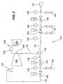
- FIG. 1depicts a schematic representation of a steam and air injection piping system in accordance with an embodiment of the present invention
- FIG. 2depicts an alternate schematic representation of a steam and air injection piping system in accordance with an embodiment of the present invention
- FIG. 3depicts a perspective view of a portion of a gas turbine engine incorporating an embodiment of the present invention
- FIG. 4depicts a perspective view of a gas turbine engine in accordance with an embodiment of the present invention
- FIG. 5depicts an alternate perspective view of a gas turbine engine in accordance with an embodiment of the present invention
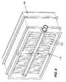
- FIG. 6depicts a perspective view of an inlet section of a gas turbine engine in accordance with an embodiment of the present invention
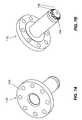
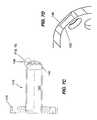
- FIGS. 7A , 7 B, 7 C, and 7 Ddepict views of a nozzle in accordance with an embodiment of the present invention
- FIG. 8depicts an illustrative method for providing power augmentation to a gas turbine engine in accordance with an embodiment of the present invention.
- FIG. 9depicts an illustrative method for providing heated compressed air to a gas turbine engine in accordance with an embodiment of the present invention.
- the present inventionprovides an embodiment of an inlet bleed heat and steam injection system 100 comprising a manifold 102 extending about at least a portion of a gas turbine engine 200 .
- the manifold for the embodiment disclosed in FIG. 1is generally U-shaped.
- a plurality of feed pipes 106are in fluid communication with the manifold 102 as well as a compressor discharge plenum 208 , which encompasses the core of engine 200 .
- the feed pipes 106are coupled to the discharge plenum 208 at a plurality of openings (not shown) that are generally equally spaced about the plenum 208 .
- each of the feed pipes 106contain a nozzle 110 (see FIGS. 3 and 7 A-D for further detail on the nozzle 110 ) proximate the openings in the plenum 208 .
- a supply pipe 112Located adjacent to manifold 102 and in fluid communication with the manifold is a supply pipe 112 .
- the supply pipe 112is coupled to a steam pipe 114 and an inlet pipe 116 by a joint 118 . This joint permits the flow of fluid between the supply pipe 112 and either of the steam pipe 114 or inlet pipe 116 .
- the steam pipe 114has a steam isolation valve 120 , a steam control valve 122 , and is in communication with a steam source 124 .
- the inlet pipe 116which is also coupled to the supply pipe 112 , has an inlet bleed heat isolation valve 126 , an inlet bleed heat control valve 128 , and is in communication with an engine inlet 130 .
- the isolation valves 120 and 126are designed to be either fully open or fully closed, whereas the control valves 122 and 128 range between fully open to fully closed so as to regulate the amount of fluid flowing therethrough.
- the steam pipe 114also includes an orifice plate 132 for measuring the flow of steam from the steam source 124 .
- FIG. 2A more detailed version of the embodiment of FIG. 1 is shown in FIG. 2 .
- the embodiment of FIG. 2shows the relation of inlet bleed heat and steam injection system 100 relative to a gas turbine engine 200 .
- the supply pipe 112is in fluid communication with a compressor discharge plenum 208 that receives compressed air from a compressor 202 and passes the fluid to at least one combustor 204 .
- the hot combustion gases from the at least one combustor 204passes to a turbine 206 .
- Arrows in FIG. 2indicate the flow direction of fluids to and from the compressor discharge plenum 208 of the engine 200 .
- the steam pipe 114also comprises a plurality of drain valves 134 which can be opened to drain condensation that can form at different locations throughout steam pipe 114 .
- a drain valve 134is also positioned in inlet pipe 116 .
- Also located in steam pipe 114 and inlet pipe 116is at least one thermocouple 136 .
- the thermocouples 136are used to measure the temperature of the fluids contained in the pipes. It is important to know the temperature of the air being directed to the compressor inlet or the steam being directed to the compressor discharge plenum so that the proper amount of fluid can be regulated by the control valves for a given operating condition.
- the inlet bleed heat and steam injection system 100is configured so as to be able to flow two different fluid mediums, either to or from the engine, depending on the operating conditions and load to the engine. However, these fluids do not flow to or from the compressor discharge plenum 208 simultaneously, as will be discussed in more detail below.
- the valves in the inlet pipeare closed and the valves to the steam pipe are opened so as to permit the flow of steam from the steam source 124 .
- valves in the steam circuitare closed and the valves to the inlet pipe are opened so as to permit the flow of air from the plenum 208 to the inlet 130 .
- the use of a common supply pipe 112 and manifold 102is more clearly shown in FIG. 3 .
- the supply pipe 112includes a “T” joint 118 for connecting the supply pipe 112 to two different fluid sources. It is joined to the inlet pipe 116 at a flange 112 a and to a steam pipe 114 at a flange 112 b .
- Also shown pictorially in FIG. 3is the general shape of the manifold 102 .
- the manifold 102for this embodiment, has a general inverted U-shape that surrounds a compressor discharge plenum on three sides. It should be understood, that this is merely one of many embodiments for a manifold, and that other manifold configurations are possible without departing from the scope of the invention.
- feed tubes 106Extending from the manifold 102 is a plurality of feed tubes 106 . These feed tubes 106 extend to openings 210 in the plenum 208 . These openings are generally equally spaced about the plenum 208 for more even fluid flow distribution. Located proximate an end of the feed tubes 106 and positioned within the plenum 208 is a nozzle 110 , which is discussed in more detail below.
- a gas turbine engine 200which utilizes a common inlet bleed heat and steam injection system.
- FIGS. 4 and 5disclose the gas turbine engine 200 in greater detail.
- the core of the engine 200comprises a compressor 202 , at least one combustor 204 , and a turbine 206 . These sections of the engine 200 are not clearly visible in FIG. 4 , but the general axial locations of these components are indicated.
- the compressor 202which as one skilled in the art understands, is generally comprised of alternating rows of stationary and rotating airfoils on a shaft in decreasing radial size so as to compress the air passing through the compressor 202 . The compressed air exits the compressor 202 and enters the compressor discharge plenum 208 .
- the compressor discharge plenumis generally annular in shape, but the shape could vary depending upon the geometry of the engine.
- the compressed air in the compressor discharge plenum 208passes to at least one combustor 204 where a mixture of compressed air and fuel reacts to form hot combustion gases.
- a plurality of can-annular combustorsare shown in a generally annular array about the shaft of engine 200 .
- the turbine 206which also comprises a series of axially spaced stationary and rotating airfoils is in fluid communication with the at least one combustor 204 .
- the turbineconverts the hot combustion gases from the combustor into mechanical work to drive the compressor and an electrical generator (not shown), since the compressor 202 is coupled to the turbine 206 by the shaft.
- the gas turbine engine 200also discloses a piping system 100 for bi-directional flow of compressed air for inlet bleed heat and steam injection for power augmentation.
- the system 100is shown positioned on the engine 200 and comprises a manifold 102 having a plurality of feed pipes 106 , with the feed pipes 106 being in fluid communication with the manifold 102 and the compressor discharge plenum 208 .
- the piping system for use on the gas turbine engine 200also comprises a supply pipe 112 which is in fluid communication with the manifold 102 .
- An inlet pipe 116is coupled to the supply pipe 112 and is in fluid communication with the inlet 130 .
- the inlet pipe 116Located within the inlet pipe 116 for controlling the flow of inlet bleed heat (compressed air) to the inlet 130 is an isolation valve 120 and a control valve 122 .
- the inlet pipe 116is in fluid communication with the supply pipe 112 and the manifold 102 , such that air drawn from the compressor discharge plenum 208 , flows out of the engine through feed tubes 106 , through the manifold 102 , through the supply pipe 112 , and through the inlet pipe 116 to the inlet 130 .
- the air passed to inlet 130is injected into the incoming ambient air by a plurality of generally vertically extending manifolds 131 that are each in fluid communication with inlet pipe 116 (see FIG.
- a steam pipe 114is also coupled to the supply pipe 112 , as previously discussed, and although not shown in FIGS. 4 and 5 , serves to direct the steam from a steam source into the compressor discharge plenum 208 by way of the supply pipe 112 , the manifold 102 , and the feed tubes 106 .
- FIG. 3Another feature of the piping system briefly discussed with respect to FIG. 3 is the nozzle 110 positioned proximate and end of feed tube 106 .
- the nozzle 110is shown in greater detail in FIGS. 7A-D .
- the nozzle 110is positioned proximate an end of the feed tube 106 that is adjacent to the compressor discharge plenum 208 and therefore opposite of the manifold 102 .
- the nozzle 110is positioned proximate the end of the feed tube 106 by a flange 140 and has an internal passage 142 and an end cap 144 .
- the end cap 144has a plurality of holes 146 that are positioned and shaped to regulate the flow of fluid through the feed tube 106 in both directions.
- the holesare shaped so as to meet the flow requirements for two different fluids, compressed air and steam. More specifically, with reference to FIG. 7D , the holes 146 have an opening with a rounded, or blended, edge 148 and an opening with a sharp edge 150 , with the sharp-edge opening located on side of hole 146 immediately adjacent the internal passage 142 . In the embodiment of the nozzle shown in FIGS. 7B-D , the holes 146 are shown in a general annular array about the end cap 144 . However, the hole position could differ depending on the flow requirements such that the holes 146 could be generally perpendicular to the end cap 144 .
- the function of the nozzle 110will be better understood when considered in context with the feed tubes 106 and the inlet bleed heat and steam injection piping system 100 .
- the steamflows in a direction from the manifold 102 , through the internal passage 142 of the feed tube 106 , and through the sharp-edge openings 150 of the nozzle 110 .
- compressor discharge airis desired to be bled from the compressor discharge plenum and injected into the inlet, the air flows in a direction from the plenum 208 through the rounded-edge openings 148 in the nozzle 110 and into the feed tube 106 for passage into the manifold 102 and to the inlet 130 .
- a method of providing power augmentation to a gas turbine enginecomprises in a step 800 providing a gas turbine engine as previously discussed having a compressor for compressing air, at least one combustor for generating hot combustion gases, and a turbine coupled to the compressor for converting the energy received from the combustor into work.
- a piping systemas previously discussed.
- the piping systemcomprises a manifold, supply pipe coupled to the manifold, a steam pipe coupled to the supply pipe, an isolation valve and control valve in the steam pipe, and an inlet pipe having an isolation valve and control valve. Coupled to the steam pipe is a steam source.
- the isolation valve and control valve in the inlet pipeIn order for the steam to be injected into the compressor discharge plenum, the isolation valve and control valve in the inlet pipe must be closed. These valves are closed prior to achieving base load conditions (above 98% load). These valves must be closed so as to prevent steam from flowing into the engine inlet. The closed valve positions in the inlet pipe are verified in a step 806 .
- the steam isolation valveis opened.
- the isolation valvehas two positions, either fully open or fully closed.
- the steam control valveis opened to release the flow of steam from the steam source to the piping system, and ultimately the compressor discharge plenum.
- the steam control valvecan be modulated in a step 812 in order to satisfy the steam demand.
- the steam flowis directed from the steam source through the piping system and into the compressor discharge plenum.
- the steam and air mix in the compressor discharge plenum and the mixtureis then directed into a combustor in a step 818 .
- a method of providing hot compressed air to a gas turbine engine inletcomprises in a step 900 providing a gas turbine engine as previously discussed having a compressor for compressing air, at least one combustor for generating hot combustion gases, and a turbine coupled to the compressor for converting the energy received from the combustor into work.
- a piping systemas previously discussed.
- the piping systemcomprises a manifold, supply pipe coupled to the manifold, a steam pipe coupled to the supply pipe, an isolation valve and control valve in the steam pipe, and an inlet pipe having an isolation valve and control valve. Coupled to the steam pipe is a steam source.
- the amount of airflow passing from the inlet to the compressorwill determine if inlet bleed heat can be utilized. As one skilled in the art will understand, the mass flow of air to the compressor is determined by the inlet guide vanes that are positioned in the engine inlet. The inlet guide vanes modulate in position from fully open to partially closed. A closing of the inlet guide vanes restricts the flow of ambient air into the inlet.
- the inlet guide vanesclose from approximately 57 degrees to approximately 48 degrees, thereby reducing the airflow passing through the engine inlet. It is under these conditions that less air is provided to the compressor and inlet bleed heat can be utilized.
- compressed air from the compressor discharge plenumis injected into the inlet the average temperature of the compressed air entering the combustor is higher, and therefore, combustor operation can be maintained in a more efficient mode (i.e. premix).
- a step 906the isolation valve and control valve in the steam pipe are verified to be in a closed position, such that hot compressed air does not travel towards or into the steam source. As with the inlet bleed heat function, the steam isolation and control valves are closed prior to achieving a speed/load condition at which inlet bleed heat can be utilized.
- the isolation valve in the inlet pipeis opened. As previously discussed the isolation valve has two positions, either fully open or fully closed.
- the control valve of the inlet pipeis opened. This opens the circuit established between the compressor discharge plenum and the inlet.
- the inlet control valvecan be modulated so as to adjust the amount of airflow passing through the valve.
- the amount of air passing through the control valveis approximately 5% of total compressor flow.
- the compressed air drawn from the compressor discharge plenumis directed through the piping system to the inlet.
- the air from the plenumis mixed with the ambient air entering the inlet and in a step 918 , this air mixture is directed to the compressor.
- the breakercan be closed between the generator and the grid.
- the position of the inlet control valvevaries.
- the inlet bleed heat control valvegradually closes as a function of inlet guide vane angle. That is, as the load on the engine increases, the inlet guide vane angle increases and the inlet control valve continues to close.
- the inlet isolation valve and inlet control valveare closed so as to stop the flow of compressor discharge air to the engine inlet. Should load decrease and the inlet guide vanes close to control exhaust temperature, the inlet valves can open again to bleed hot compressed air into the engine inlet, if inlet bleed heat is still desired.
Landscapes
- Engineering & Computer Science (AREA)
- Chemical & Material Sciences (AREA)
- Combustion & Propulsion (AREA)
- Mechanical Engineering (AREA)
- General Engineering & Computer Science (AREA)
- Engine Equipment That Uses Special Cycles (AREA)
Abstract
Description
Claims (24)
Priority Applications (1)
| Application Number | Priority Date | Filing Date | Title |
|---|---|---|---|
| US11/669,257US7841186B2 (en) | 2007-01-31 | 2007-01-31 | Inlet bleed heat and power augmentation for a gas turbine engine |
Applications Claiming Priority (1)
| Application Number | Priority Date | Filing Date | Title |
|---|---|---|---|
| US11/669,257US7841186B2 (en) | 2007-01-31 | 2007-01-31 | Inlet bleed heat and power augmentation for a gas turbine engine |
Publications (2)
| Publication Number | Publication Date |
|---|---|
| US20080178571A1 US20080178571A1 (en) | 2008-07-31 |
| US7841186B2true US7841186B2 (en) | 2010-11-30 |
Family
ID=39666385
Family Applications (1)
| Application Number | Title | Priority Date | Filing Date |
|---|---|---|---|
| US11/669,257Active2029-10-01US7841186B2 (en) | 2007-01-31 | 2007-01-31 | Inlet bleed heat and power augmentation for a gas turbine engine |
Country Status (1)
| Country | Link |
|---|---|
| US (1) | US7841186B2 (en) |
Cited By (73)
| Publication number | Priority date | Publication date | Assignee | Title |
|---|---|---|---|---|
| US20090241552A1 (en)* | 2008-03-26 | 2009-10-01 | Alstom Technologies, Ltd., Llc | Utilizing inlet bleed heat to improve mixing and engine turndown |
| US20130133857A1 (en)* | 2011-11-30 | 2013-05-30 | Lockheed Martin Corporation | Exhaust impingement cooling |
| US20130199150A1 (en)* | 2012-02-03 | 2013-08-08 | General Electric Company | Steam injection assembly for a combined cycle system |
| US20140060068A1 (en)* | 2012-09-05 | 2014-03-06 | Ching-Pang Lee | Method for operating a gas turbine engine including a combustor shell air recirculation system |
| US8734545B2 (en) | 2008-03-28 | 2014-05-27 | Exxonmobil Upstream Research Company | Low emission power generation and hydrocarbon recovery systems and methods |
| US8904747B2 (en) | 2011-07-01 | 2014-12-09 | General Electric Company | Gas turbine inlet heating system |
| US8926265B2 (en) | 2011-11-08 | 2015-01-06 | General Electric Company | Inlet bleed heat system |
| US8932004B2 (en) | 2011-11-08 | 2015-01-13 | General Electric Company | Inlet bleed heat system |
| US8984857B2 (en) | 2008-03-28 | 2015-03-24 | Exxonmobil Upstream Research Company | Low emission power generation and hydrocarbon recovery systems and methods |
| US20150089955A1 (en)* | 2013-10-01 | 2015-04-02 | Alstom Technology Ltd. | Gas turbine with cooling air cooling system and method for operation of a gas turbine at low part load |
| US9027321B2 (en) | 2008-03-28 | 2015-05-12 | Exxonmobil Upstream Research Company | Low emission power generation and hydrocarbon recovery systems and methods |
| US9222671B2 (en) | 2008-10-14 | 2015-12-29 | Exxonmobil Upstream Research Company | Methods and systems for controlling the products of combustion |
| US20160040596A1 (en)* | 2014-08-08 | 2016-02-11 | General Electric Company | Turbomachine system including an inlet bleed heat system and method of operating a turbomachine at part load |
| US9353682B2 (en) | 2012-04-12 | 2016-05-31 | General Electric Company | Methods, systems and apparatus relating to combustion turbine power plants with exhaust gas recirculation |
| US9463417B2 (en) | 2011-03-22 | 2016-10-11 | Exxonmobil Upstream Research Company | Low emission power generation systems and methods incorporating carbon dioxide separation |
| US9512759B2 (en) | 2013-02-06 | 2016-12-06 | General Electric Company | System and method for catalyst heat utilization for gas turbine with exhaust gas recirculation |
| US9574496B2 (en) | 2012-12-28 | 2017-02-21 | General Electric Company | System and method for a turbine combustor |
| US9581081B2 (en) | 2013-01-13 | 2017-02-28 | General Electric Company | System and method for protecting components in a gas turbine engine with exhaust gas recirculation |
| US9587510B2 (en) | 2013-07-30 | 2017-03-07 | General Electric Company | System and method for a gas turbine engine sensor |
| US9599021B2 (en) | 2011-03-22 | 2017-03-21 | Exxonmobil Upstream Research Company | Systems and methods for controlling stoichiometric combustion in low emission turbine systems |
| US9599070B2 (en) | 2012-11-02 | 2017-03-21 | General Electric Company | System and method for oxidant compression in a stoichiometric exhaust gas recirculation gas turbine system |
| US9611756B2 (en) | 2012-11-02 | 2017-04-04 | General Electric Company | System and method for protecting components in a gas turbine engine with exhaust gas recirculation |
| US9617914B2 (en) | 2013-06-28 | 2017-04-11 | General Electric Company | Systems and methods for monitoring gas turbine systems having exhaust gas recirculation |
| US9618261B2 (en) | 2013-03-08 | 2017-04-11 | Exxonmobil Upstream Research Company | Power generation and LNG production |
| US9631815B2 (en) | 2012-12-28 | 2017-04-25 | General Electric Company | System and method for a turbine combustor |
| US9631542B2 (en) | 2013-06-28 | 2017-04-25 | General Electric Company | System and method for exhausting combustion gases from gas turbine engines |
| US9670841B2 (en) | 2011-03-22 | 2017-06-06 | Exxonmobil Upstream Research Company | Methods of varying low emission turbine gas recycle circuits and systems and apparatus related thereto |
| US9689309B2 (en) | 2011-03-22 | 2017-06-27 | Exxonmobil Upstream Research Company | Systems and methods for carbon dioxide capture in low emission combined turbine systems |
| US9708977B2 (en) | 2012-12-28 | 2017-07-18 | General Electric Company | System and method for reheat in gas turbine with exhaust gas recirculation |
| US9719418B2 (en) | 2013-04-01 | 2017-08-01 | General Electric Company | Turbomachine inlet bleed heating assembly |
| US9732673B2 (en) | 2010-07-02 | 2017-08-15 | Exxonmobil Upstream Research Company | Stoichiometric combustion with exhaust gas recirculation and direct contact cooler |
| US9732675B2 (en) | 2010-07-02 | 2017-08-15 | Exxonmobil Upstream Research Company | Low emission power generation systems and methods |
| US9752458B2 (en) | 2013-12-04 | 2017-09-05 | General Electric Company | System and method for a gas turbine engine |
| US9784140B2 (en) | 2013-03-08 | 2017-10-10 | Exxonmobil Upstream Research Company | Processing exhaust for use in enhanced oil recovery |
| US9784182B2 (en) | 2013-03-08 | 2017-10-10 | Exxonmobil Upstream Research Company | Power generation and methane recovery from methane hydrates |
| US9784185B2 (en) | 2012-04-26 | 2017-10-10 | General Electric Company | System and method for cooling a gas turbine with an exhaust gas provided by the gas turbine |
| US9803865B2 (en) | 2012-12-28 | 2017-10-31 | General Electric Company | System and method for a turbine combustor |
| US9810050B2 (en) | 2011-12-20 | 2017-11-07 | Exxonmobil Upstream Research Company | Enhanced coal-bed methane production |
| US9819292B2 (en) | 2014-12-31 | 2017-11-14 | General Electric Company | Systems and methods to respond to grid overfrequency events for a stoichiometric exhaust recirculation gas turbine |
| US9835089B2 (en) | 2013-06-28 | 2017-12-05 | General Electric Company | System and method for a fuel nozzle |
| US9863267B2 (en) | 2014-01-21 | 2018-01-09 | General Electric Company | System and method of control for a gas turbine engine |
| US9869279B2 (en) | 2012-11-02 | 2018-01-16 | General Electric Company | System and method for a multi-wall turbine combustor |
| US9869247B2 (en) | 2014-12-31 | 2018-01-16 | General Electric Company | Systems and methods of estimating a combustion equivalence ratio in a gas turbine with exhaust gas recirculation |
| US9885290B2 (en) | 2014-06-30 | 2018-02-06 | General Electric Company | Erosion suppression system and method in an exhaust gas recirculation gas turbine system |
| US9903271B2 (en) | 2010-07-02 | 2018-02-27 | Exxonmobil Upstream Research Company | Low emission triple-cycle power generation and CO2 separation systems and methods |
| US9903588B2 (en) | 2013-07-30 | 2018-02-27 | General Electric Company | System and method for barrier in passage of combustor of gas turbine engine with exhaust gas recirculation |
| US9903316B2 (en) | 2010-07-02 | 2018-02-27 | Exxonmobil Upstream Research Company | Stoichiometric combustion of enriched air with exhaust gas recirculation |
| US9915200B2 (en) | 2014-01-21 | 2018-03-13 | General Electric Company | System and method for controlling the combustion process in a gas turbine operating with exhaust gas recirculation |
| US9932874B2 (en) | 2013-02-21 | 2018-04-03 | Exxonmobil Upstream Research Company | Reducing oxygen in a gas turbine exhaust |
| US9938861B2 (en) | 2013-02-21 | 2018-04-10 | Exxonmobil Upstream Research Company | Fuel combusting method |
| US9951658B2 (en) | 2013-07-31 | 2018-04-24 | General Electric Company | System and method for an oxidant heating system |
| US10012151B2 (en) | 2013-06-28 | 2018-07-03 | General Electric Company | Systems and methods for controlling exhaust gas flow in exhaust gas recirculation gas turbine systems |
| US10030588B2 (en) | 2013-12-04 | 2018-07-24 | General Electric Company | Gas turbine combustor diagnostic system and method |
| US10047633B2 (en) | 2014-05-16 | 2018-08-14 | General Electric Company | Bearing housing |
| US10060359B2 (en) | 2014-06-30 | 2018-08-28 | General Electric Company | Method and system for combustion control for gas turbine system with exhaust gas recirculation |
| US10079564B2 (en) | 2014-01-27 | 2018-09-18 | General Electric Company | System and method for a stoichiometric exhaust gas recirculation gas turbine system |
| US20180274445A1 (en)* | 2017-03-21 | 2018-09-27 | General Electric Company | Inlet Bleed Heat Duct Assembly |
| US10094566B2 (en) | 2015-02-04 | 2018-10-09 | General Electric Company | Systems and methods for high volumetric oxidant flow in gas turbine engine with exhaust gas recirculation |
| US10100741B2 (en) | 2012-11-02 | 2018-10-16 | General Electric Company | System and method for diffusion combustion with oxidant-diluent mixing in a stoichiometric exhaust gas recirculation gas turbine system |
| US10107495B2 (en) | 2012-11-02 | 2018-10-23 | General Electric Company | Gas turbine combustor control system for stoichiometric combustion in the presence of a diluent |
| US10145269B2 (en) | 2015-03-04 | 2018-12-04 | General Electric Company | System and method for cooling discharge flow |
| US10208677B2 (en) | 2012-12-31 | 2019-02-19 | General Electric Company | Gas turbine load control system |
| US10215412B2 (en) | 2012-11-02 | 2019-02-26 | General Electric Company | System and method for load control with diffusion combustion in a stoichiometric exhaust gas recirculation gas turbine system |
| US10221762B2 (en) | 2013-02-28 | 2019-03-05 | General Electric Company | System and method for a turbine combustor |
| US10227920B2 (en) | 2014-01-15 | 2019-03-12 | General Electric Company | Gas turbine oxidant separation system |
| US10253690B2 (en) | 2015-02-04 | 2019-04-09 | General Electric Company | Turbine system with exhaust gas recirculation, separation and extraction |
| US10267270B2 (en) | 2015-02-06 | 2019-04-23 | General Electric Company | Systems and methods for carbon black production with a gas turbine engine having exhaust gas recirculation |
| US10273880B2 (en) | 2012-04-26 | 2019-04-30 | General Electric Company | System and method of recirculating exhaust gas for use in a plurality of flow paths in a gas turbine engine |
| US10315150B2 (en) | 2013-03-08 | 2019-06-11 | Exxonmobil Upstream Research Company | Carbon dioxide recovery |
| US10316746B2 (en) | 2015-02-04 | 2019-06-11 | General Electric Company | Turbine system with exhaust gas recirculation, separation and extraction |
| US10480792B2 (en) | 2015-03-06 | 2019-11-19 | General Electric Company | Fuel staging in a gas turbine engine |
| US10655542B2 (en) | 2014-06-30 | 2020-05-19 | General Electric Company | Method and system for startup of gas turbine system drive trains with exhaust gas recirculation |
| US10788212B2 (en) | 2015-01-12 | 2020-09-29 | General Electric Company | System and method for an oxidant passageway in a gas turbine system with exhaust gas recirculation |
Families Citing this family (12)
| Publication number | Priority date | Publication date | Assignee | Title |
|---|---|---|---|---|
| US9376931B2 (en)* | 2012-01-27 | 2016-06-28 | General Electric Company | Turbomachine passage cleaning system |
| US9816391B2 (en) | 2012-11-07 | 2017-11-14 | General Electric Company | Compressor wash system with spheroids |
| US20150159509A1 (en)* | 2013-12-06 | 2015-06-11 | General Electric Company | Method and System for Dispensing Gas Turbine Anticorrosive Protection |
| USD810785S1 (en)* | 2015-01-09 | 2018-02-20 | Siemens Aktiengesellschaft | Concentric shoveled manifold |
| CN105114180A (en)* | 2015-08-26 | 2015-12-02 | 成都博世德能源科技股份有限公司 | Heat preservation type air inlet system used for gas turbine |
| US20170292456A1 (en)* | 2016-04-12 | 2017-10-12 | General Electric Company | Integrated gas turbine inlet silencer and bleed heat system |
| CN106762153A (en)* | 2016-12-26 | 2017-05-31 | 江苏华强新能源科技有限公司 | A kind of gas turbine inlet air heater |
| US20210317782A1 (en)* | 2020-04-09 | 2021-10-14 | General Electric Company | Modeling and control of gas cycle power plant operation by varying split load for multiple gas turbines |
| US11525375B2 (en) | 2020-04-09 | 2022-12-13 | General Electric Company | Modeling and control of gas cycle power plant operation with variant control profile |
| US11802509B2 (en) | 2021-06-25 | 2023-10-31 | Pratt & Whitney Canada Corp. | Air filtration system and method for compressor bleed valve |
| US11852073B2 (en) | 2021-07-30 | 2023-12-26 | Pratt & Whitney Canada Corp. | Orifice pack for compressor bleed valve |
| US11639689B2 (en)* | 2021-09-17 | 2023-05-02 | Pratt & Whitney Canada Corp. | Intake device for gas turbine engine |
Citations (23)
| Publication number | Priority date | Publication date | Assignee | Title |
|---|---|---|---|---|
| US3705491A (en)* | 1970-06-30 | 1972-12-12 | Richard W Foster Pegg | Jet engine air compressor |
| US3747336A (en)* | 1972-03-29 | 1973-07-24 | Gen Electric | Steam injection system for a gas turbine |
| US4157010A (en) | 1977-06-03 | 1979-06-05 | General Electric Company | Gas turbine engine with power modulation capability |
| US4214435A (en)* | 1977-07-25 | 1980-07-29 | General Electric Company | Method for reducing nitrous oxide emissions from a gas turbine engine |
| US5163282A (en)* | 1991-07-19 | 1992-11-17 | Shell Oil Company | Turbine process |
| US5435123A (en)* | 1991-05-25 | 1995-07-25 | Saarbergwerke Aktiengesellschaft | Environmentally acceptable electric energy generation process and plant |
| US5540045A (en) | 1990-11-27 | 1996-07-30 | Rolls-Royce Plc | Steam injection system for a combustion turbine gas generator |
| US5560195A (en) | 1995-02-13 | 1996-10-01 | General Electric Co. | Gas turbine inlet heating system using jet blower |
| US6027304A (en) | 1998-05-27 | 2000-02-22 | General Electric Co. | High pressure inlet bleed heat system for the compressor of a turbine |
| US6293088B1 (en)* | 1999-11-29 | 2001-09-25 | Siemens Westinghouse Power Corporation | Gas turbine with steam cooling and fuel atomization |
| US6446440B1 (en) | 2000-09-15 | 2002-09-10 | General Electric Company | Steam injection and inlet fogging in a gas turbine power cycle and related method |
| US6499303B1 (en) | 2001-04-18 | 2002-12-31 | General Electric Company | Method and system for gas turbine power augmentation |
| US6526758B2 (en) | 2000-05-12 | 2003-03-04 | General Electric Company | Method and apparatus for power augmentation for gas turbine power cycles |
| US6534234B1 (en) | 1997-10-03 | 2003-03-18 | Fuji Photo Film Co., Ltd. | Package of photosensitive planographic printing plates and photosensitive planographic printing plate |
| US6634165B2 (en)* | 2000-12-28 | 2003-10-21 | General Electric Company | Control system for gas turbine inlet-air water-saturation and supersaturation system |
| US6685425B2 (en) | 2002-06-26 | 2004-02-03 | General Electric Company | Inlet bleed heater for heating inlet air to a compressor and methods of fabricating and transporting the heater |
| US6779346B2 (en) | 2002-12-09 | 2004-08-24 | General Electric Company | Control of gas turbine combustion temperature by compressor bleed air |
| US20040221584A1 (en)* | 2001-11-02 | 2004-11-11 | Jurgen Hoffmann | Process for controlling the cooling air mass flow of a gas turbine set |
| US20050097898A1 (en)* | 1999-11-10 | 2005-05-12 | Hitachi, Ltd. | Gas turbine unit and its cooling method |
| US6901761B1 (en)* | 2004-02-24 | 2005-06-07 | General Electric Company | System and method for regulating pressure of pilot air to combustor of gas turbine |
| US7353655B2 (en)* | 2001-12-06 | 2008-04-08 | Alstom Technology Ltd | Method and apparatus for achieving power augmentation in gas turbine using wet compression |
| US7441399B2 (en)* | 1995-12-28 | 2008-10-28 | Hitachi, Ltd. | Gas turbine, combined cycle plant and compressor |
| US7587887B2 (en)* | 2004-06-30 | 2009-09-15 | Hitachi, Ltd. | Advanced humid air turbine power plant |
- 2007
- 2007-01-31USUS11/669,257patent/US7841186B2/enactiveActive
Patent Citations (24)
| Publication number | Priority date | Publication date | Assignee | Title |
|---|---|---|---|---|
| US3705491A (en)* | 1970-06-30 | 1972-12-12 | Richard W Foster Pegg | Jet engine air compressor |
| US3747336A (en)* | 1972-03-29 | 1973-07-24 | Gen Electric | Steam injection system for a gas turbine |
| US4157010A (en) | 1977-06-03 | 1979-06-05 | General Electric Company | Gas turbine engine with power modulation capability |
| US4214435A (en)* | 1977-07-25 | 1980-07-29 | General Electric Company | Method for reducing nitrous oxide emissions from a gas turbine engine |
| US5720164A (en) | 1990-11-27 | 1998-02-24 | Rolls-Royce Plc | Gas generators having dual fuel injector purge means |
| US5540045A (en) | 1990-11-27 | 1996-07-30 | Rolls-Royce Plc | Steam injection system for a combustion turbine gas generator |
| US5435123A (en)* | 1991-05-25 | 1995-07-25 | Saarbergwerke Aktiengesellschaft | Environmentally acceptable electric energy generation process and plant |
| US5163282A (en)* | 1991-07-19 | 1992-11-17 | Shell Oil Company | Turbine process |
| US5560195A (en) | 1995-02-13 | 1996-10-01 | General Electric Co. | Gas turbine inlet heating system using jet blower |
| US7441399B2 (en)* | 1995-12-28 | 2008-10-28 | Hitachi, Ltd. | Gas turbine, combined cycle plant and compressor |
| US6534234B1 (en) | 1997-10-03 | 2003-03-18 | Fuji Photo Film Co., Ltd. | Package of photosensitive planographic printing plates and photosensitive planographic printing plate |
| US6027304A (en) | 1998-05-27 | 2000-02-22 | General Electric Co. | High pressure inlet bleed heat system for the compressor of a turbine |
| US20050097898A1 (en)* | 1999-11-10 | 2005-05-12 | Hitachi, Ltd. | Gas turbine unit and its cooling method |
| US6293088B1 (en)* | 1999-11-29 | 2001-09-25 | Siemens Westinghouse Power Corporation | Gas turbine with steam cooling and fuel atomization |
| US6526758B2 (en) | 2000-05-12 | 2003-03-04 | General Electric Company | Method and apparatus for power augmentation for gas turbine power cycles |
| US6446440B1 (en) | 2000-09-15 | 2002-09-10 | General Electric Company | Steam injection and inlet fogging in a gas turbine power cycle and related method |
| US6634165B2 (en)* | 2000-12-28 | 2003-10-21 | General Electric Company | Control system for gas turbine inlet-air water-saturation and supersaturation system |
| US6499303B1 (en) | 2001-04-18 | 2002-12-31 | General Electric Company | Method and system for gas turbine power augmentation |
| US20040221584A1 (en)* | 2001-11-02 | 2004-11-11 | Jurgen Hoffmann | Process for controlling the cooling air mass flow of a gas turbine set |
| US7353655B2 (en)* | 2001-12-06 | 2008-04-08 | Alstom Technology Ltd | Method and apparatus for achieving power augmentation in gas turbine using wet compression |
| US6685425B2 (en) | 2002-06-26 | 2004-02-03 | General Electric Company | Inlet bleed heater for heating inlet air to a compressor and methods of fabricating and transporting the heater |
| US6779346B2 (en) | 2002-12-09 | 2004-08-24 | General Electric Company | Control of gas turbine combustion temperature by compressor bleed air |
| US6901761B1 (en)* | 2004-02-24 | 2005-06-07 | General Electric Company | System and method for regulating pressure of pilot air to combustor of gas turbine |
| US7587887B2 (en)* | 2004-06-30 | 2009-09-15 | Hitachi, Ltd. | Advanced humid air turbine power plant |
Cited By (87)
| Publication number | Priority date | Publication date | Assignee | Title |
|---|---|---|---|---|
| US8001789B2 (en)* | 2008-03-26 | 2011-08-23 | Alstom Technologies Ltd., Llc | Utilizing inlet bleed heat to improve mixing and engine turndown |
| US20090241552A1 (en)* | 2008-03-26 | 2009-10-01 | Alstom Technologies, Ltd., Llc | Utilizing inlet bleed heat to improve mixing and engine turndown |
| US8984857B2 (en) | 2008-03-28 | 2015-03-24 | Exxonmobil Upstream Research Company | Low emission power generation and hydrocarbon recovery systems and methods |
| US8734545B2 (en) | 2008-03-28 | 2014-05-27 | Exxonmobil Upstream Research Company | Low emission power generation and hydrocarbon recovery systems and methods |
| US9027321B2 (en) | 2008-03-28 | 2015-05-12 | Exxonmobil Upstream Research Company | Low emission power generation and hydrocarbon recovery systems and methods |
| US9719682B2 (en) | 2008-10-14 | 2017-08-01 | Exxonmobil Upstream Research Company | Methods and systems for controlling the products of combustion |
| US9222671B2 (en) | 2008-10-14 | 2015-12-29 | Exxonmobil Upstream Research Company | Methods and systems for controlling the products of combustion |
| US10495306B2 (en) | 2008-10-14 | 2019-12-03 | Exxonmobil Upstream Research Company | Methods and systems for controlling the products of combustion |
| US9732673B2 (en) | 2010-07-02 | 2017-08-15 | Exxonmobil Upstream Research Company | Stoichiometric combustion with exhaust gas recirculation and direct contact cooler |
| US9903271B2 (en) | 2010-07-02 | 2018-02-27 | Exxonmobil Upstream Research Company | Low emission triple-cycle power generation and CO2 separation systems and methods |
| US9732675B2 (en) | 2010-07-02 | 2017-08-15 | Exxonmobil Upstream Research Company | Low emission power generation systems and methods |
| US9903316B2 (en) | 2010-07-02 | 2018-02-27 | Exxonmobil Upstream Research Company | Stoichiometric combustion of enriched air with exhaust gas recirculation |
| US9599021B2 (en) | 2011-03-22 | 2017-03-21 | Exxonmobil Upstream Research Company | Systems and methods for controlling stoichiometric combustion in low emission turbine systems |
| US9670841B2 (en) | 2011-03-22 | 2017-06-06 | Exxonmobil Upstream Research Company | Methods of varying low emission turbine gas recycle circuits and systems and apparatus related thereto |
| US9463417B2 (en) | 2011-03-22 | 2016-10-11 | Exxonmobil Upstream Research Company | Low emission power generation systems and methods incorporating carbon dioxide separation |
| US9689309B2 (en) | 2011-03-22 | 2017-06-27 | Exxonmobil Upstream Research Company | Systems and methods for carbon dioxide capture in low emission combined turbine systems |
| US8904747B2 (en) | 2011-07-01 | 2014-12-09 | General Electric Company | Gas turbine inlet heating system |
| US8932004B2 (en) | 2011-11-08 | 2015-01-13 | General Electric Company | Inlet bleed heat system |
| US8926265B2 (en) | 2011-11-08 | 2015-01-06 | General Electric Company | Inlet bleed heat system |
| US9995181B2 (en)* | 2011-11-30 | 2018-06-12 | Lockheed Martin Corporation | Exhaust impingement cooling |
| US20130133857A1 (en)* | 2011-11-30 | 2013-05-30 | Lockheed Martin Corporation | Exhaust impingement cooling |
| US9810050B2 (en) | 2011-12-20 | 2017-11-07 | Exxonmobil Upstream Research Company | Enhanced coal-bed methane production |
| US20130199150A1 (en)* | 2012-02-03 | 2013-08-08 | General Electric Company | Steam injection assembly for a combined cycle system |
| US9353682B2 (en) | 2012-04-12 | 2016-05-31 | General Electric Company | Methods, systems and apparatus relating to combustion turbine power plants with exhaust gas recirculation |
| US10273880B2 (en) | 2012-04-26 | 2019-04-30 | General Electric Company | System and method of recirculating exhaust gas for use in a plurality of flow paths in a gas turbine engine |
| US9784185B2 (en) | 2012-04-26 | 2017-10-10 | General Electric Company | System and method for cooling a gas turbine with an exhaust gas provided by the gas turbine |
| US8820090B2 (en)* | 2012-09-05 | 2014-09-02 | Siemens Aktiengesellschaft | Method for operating a gas turbine engine including a combustor shell air recirculation system |
| US20140060068A1 (en)* | 2012-09-05 | 2014-03-06 | Ching-Pang Lee | Method for operating a gas turbine engine including a combustor shell air recirculation system |
| US10107495B2 (en) | 2012-11-02 | 2018-10-23 | General Electric Company | Gas turbine combustor control system for stoichiometric combustion in the presence of a diluent |
| US9611756B2 (en) | 2012-11-02 | 2017-04-04 | General Electric Company | System and method for protecting components in a gas turbine engine with exhaust gas recirculation |
| US10138815B2 (en) | 2012-11-02 | 2018-11-27 | General Electric Company | System and method for diffusion combustion in a stoichiometric exhaust gas recirculation gas turbine system |
| US10683801B2 (en) | 2012-11-02 | 2020-06-16 | General Electric Company | System and method for oxidant compression in a stoichiometric exhaust gas recirculation gas turbine system |
| US9869279B2 (en) | 2012-11-02 | 2018-01-16 | General Electric Company | System and method for a multi-wall turbine combustor |
| US10161312B2 (en) | 2012-11-02 | 2018-12-25 | General Electric Company | System and method for diffusion combustion with fuel-diluent mixing in a stoichiometric exhaust gas recirculation gas turbine system |
| US10215412B2 (en) | 2012-11-02 | 2019-02-26 | General Electric Company | System and method for load control with diffusion combustion in a stoichiometric exhaust gas recirculation gas turbine system |
| US10100741B2 (en) | 2012-11-02 | 2018-10-16 | General Electric Company | System and method for diffusion combustion with oxidant-diluent mixing in a stoichiometric exhaust gas recirculation gas turbine system |
| US9599070B2 (en) | 2012-11-02 | 2017-03-21 | General Electric Company | System and method for oxidant compression in a stoichiometric exhaust gas recirculation gas turbine system |
| US9574496B2 (en) | 2012-12-28 | 2017-02-21 | General Electric Company | System and method for a turbine combustor |
| US9803865B2 (en) | 2012-12-28 | 2017-10-31 | General Electric Company | System and method for a turbine combustor |
| US9631815B2 (en) | 2012-12-28 | 2017-04-25 | General Electric Company | System and method for a turbine combustor |
| US9708977B2 (en) | 2012-12-28 | 2017-07-18 | General Electric Company | System and method for reheat in gas turbine with exhaust gas recirculation |
| US10208677B2 (en) | 2012-12-31 | 2019-02-19 | General Electric Company | Gas turbine load control system |
| US9581081B2 (en) | 2013-01-13 | 2017-02-28 | General Electric Company | System and method for protecting components in a gas turbine engine with exhaust gas recirculation |
| US9512759B2 (en) | 2013-02-06 | 2016-12-06 | General Electric Company | System and method for catalyst heat utilization for gas turbine with exhaust gas recirculation |
| US9932874B2 (en) | 2013-02-21 | 2018-04-03 | Exxonmobil Upstream Research Company | Reducing oxygen in a gas turbine exhaust |
| US9938861B2 (en) | 2013-02-21 | 2018-04-10 | Exxonmobil Upstream Research Company | Fuel combusting method |
| US10082063B2 (en) | 2013-02-21 | 2018-09-25 | Exxonmobil Upstream Research Company | Reducing oxygen in a gas turbine exhaust |
| US10221762B2 (en) | 2013-02-28 | 2019-03-05 | General Electric Company | System and method for a turbine combustor |
| US9784140B2 (en) | 2013-03-08 | 2017-10-10 | Exxonmobil Upstream Research Company | Processing exhaust for use in enhanced oil recovery |
| US10315150B2 (en) | 2013-03-08 | 2019-06-11 | Exxonmobil Upstream Research Company | Carbon dioxide recovery |
| US9784182B2 (en) | 2013-03-08 | 2017-10-10 | Exxonmobil Upstream Research Company | Power generation and methane recovery from methane hydrates |
| US9618261B2 (en) | 2013-03-08 | 2017-04-11 | Exxonmobil Upstream Research Company | Power generation and LNG production |
| US9719418B2 (en) | 2013-04-01 | 2017-08-01 | General Electric Company | Turbomachine inlet bleed heating assembly |
| US9835089B2 (en) | 2013-06-28 | 2017-12-05 | General Electric Company | System and method for a fuel nozzle |
| US9631542B2 (en) | 2013-06-28 | 2017-04-25 | General Electric Company | System and method for exhausting combustion gases from gas turbine engines |
| US9617914B2 (en) | 2013-06-28 | 2017-04-11 | General Electric Company | Systems and methods for monitoring gas turbine systems having exhaust gas recirculation |
| US10012151B2 (en) | 2013-06-28 | 2018-07-03 | General Electric Company | Systems and methods for controlling exhaust gas flow in exhaust gas recirculation gas turbine systems |
| US9587510B2 (en) | 2013-07-30 | 2017-03-07 | General Electric Company | System and method for a gas turbine engine sensor |
| US9903588B2 (en) | 2013-07-30 | 2018-02-27 | General Electric Company | System and method for barrier in passage of combustor of gas turbine engine with exhaust gas recirculation |
| US9951658B2 (en) | 2013-07-31 | 2018-04-24 | General Electric Company | System and method for an oxidant heating system |
| US20150089955A1 (en)* | 2013-10-01 | 2015-04-02 | Alstom Technology Ltd. | Gas turbine with cooling air cooling system and method for operation of a gas turbine at low part load |
| US10030588B2 (en) | 2013-12-04 | 2018-07-24 | General Electric Company | Gas turbine combustor diagnostic system and method |
| US10731512B2 (en) | 2013-12-04 | 2020-08-04 | Exxonmobil Upstream Research Company | System and method for a gas turbine engine |
| US10900420B2 (en) | 2013-12-04 | 2021-01-26 | Exxonmobil Upstream Research Company | Gas turbine combustor diagnostic system and method |
| US9752458B2 (en) | 2013-12-04 | 2017-09-05 | General Electric Company | System and method for a gas turbine engine |
| US10227920B2 (en) | 2014-01-15 | 2019-03-12 | General Electric Company | Gas turbine oxidant separation system |
| US9915200B2 (en) | 2014-01-21 | 2018-03-13 | General Electric Company | System and method for controlling the combustion process in a gas turbine operating with exhaust gas recirculation |
| US9863267B2 (en) | 2014-01-21 | 2018-01-09 | General Electric Company | System and method of control for a gas turbine engine |
| US10727768B2 (en) | 2014-01-27 | 2020-07-28 | Exxonmobil Upstream Research Company | System and method for a stoichiometric exhaust gas recirculation gas turbine system |
| US10079564B2 (en) | 2014-01-27 | 2018-09-18 | General Electric Company | System and method for a stoichiometric exhaust gas recirculation gas turbine system |
| US10047633B2 (en) | 2014-05-16 | 2018-08-14 | General Electric Company | Bearing housing |
| US10655542B2 (en) | 2014-06-30 | 2020-05-19 | General Electric Company | Method and system for startup of gas turbine system drive trains with exhaust gas recirculation |
| US9885290B2 (en) | 2014-06-30 | 2018-02-06 | General Electric Company | Erosion suppression system and method in an exhaust gas recirculation gas turbine system |
| US10738711B2 (en) | 2014-06-30 | 2020-08-11 | Exxonmobil Upstream Research Company | Erosion suppression system and method in an exhaust gas recirculation gas turbine system |
| US10060359B2 (en) | 2014-06-30 | 2018-08-28 | General Electric Company | Method and system for combustion control for gas turbine system with exhaust gas recirculation |
| US20160040596A1 (en)* | 2014-08-08 | 2016-02-11 | General Electric Company | Turbomachine system including an inlet bleed heat system and method of operating a turbomachine at part load |
| US9869247B2 (en) | 2014-12-31 | 2018-01-16 | General Electric Company | Systems and methods of estimating a combustion equivalence ratio in a gas turbine with exhaust gas recirculation |
| US9819292B2 (en) | 2014-12-31 | 2017-11-14 | General Electric Company | Systems and methods to respond to grid overfrequency events for a stoichiometric exhaust recirculation gas turbine |
| US10788212B2 (en) | 2015-01-12 | 2020-09-29 | General Electric Company | System and method for an oxidant passageway in a gas turbine system with exhaust gas recirculation |
| US10253690B2 (en) | 2015-02-04 | 2019-04-09 | General Electric Company | Turbine system with exhaust gas recirculation, separation and extraction |
| US10316746B2 (en) | 2015-02-04 | 2019-06-11 | General Electric Company | Turbine system with exhaust gas recirculation, separation and extraction |
| US10094566B2 (en) | 2015-02-04 | 2018-10-09 | General Electric Company | Systems and methods for high volumetric oxidant flow in gas turbine engine with exhaust gas recirculation |
| US10267270B2 (en) | 2015-02-06 | 2019-04-23 | General Electric Company | Systems and methods for carbon black production with a gas turbine engine having exhaust gas recirculation |
| US10145269B2 (en) | 2015-03-04 | 2018-12-04 | General Electric Company | System and method for cooling discharge flow |
| US10968781B2 (en) | 2015-03-04 | 2021-04-06 | General Electric Company | System and method for cooling discharge flow |
| US10480792B2 (en) | 2015-03-06 | 2019-11-19 | General Electric Company | Fuel staging in a gas turbine engine |
| US20180274445A1 (en)* | 2017-03-21 | 2018-09-27 | General Electric Company | Inlet Bleed Heat Duct Assembly |
Also Published As
| Publication number | Publication date |
|---|---|
| US20080178571A1 (en) | 2008-07-31 |
Similar Documents
| Publication | Publication Date | Title |
|---|---|---|
| US7841186B2 (en) | Inlet bleed heat and power augmentation for a gas turbine engine | |
| US10415432B2 (en) | Power plant with steam generation and fuel heating capabilities | |
| CN101737801B (en) | Integrated combustor and stage 1 nozzle in a gas turbine and method | |
| US10077694B2 (en) | Power generation system exhaust cooling | |
| CN106762158B (en) | System and method for operating a gas turbine while maintaining emissions standards | |
| US10436073B2 (en) | System for generating steam via turbine extraction and compressor extraction | |
| US9874143B2 (en) | System for generating steam and for providing cooled combustion gas to a secondary gas turbine combustor | |
| AU2009202911A1 (en) | Turbomachine injection nozzle including a coolant delivery system | |
| US10060316B2 (en) | Power generation system exhaust cooling | |
| US10415476B2 (en) | System for generating steam and for providing cooled combustion gas to a secondary gas turbine | |
| US10584615B2 (en) | System for generating steam via turbine extraction and compressor extraction including an ejector and static mixer | |
| US10072573B2 (en) | Power plant including an ejector and steam generating system via turbine extraction | |
| EP3181858A1 (en) | Power plant with steam generation via combustor gas extraction | |
| EP3321581B1 (en) | Combustor with auto-thermal valve for passively controlling fuel flow to axial fuel stage of gas turbine | |
| US10577982B2 (en) | Power plant with steam generation via turbine extraction and including a gas distribution manifold | |
| US9964035B2 (en) | Power plant including exhaust gas coolant injection system and steam generating system via turbine extraction | |
| EP3321590A1 (en) | Auto-thermal fuel nozzle flow modulation | |
| US20150377126A1 (en) | Combined Gas Turbine Auxiliary Systems | |
| US20170058770A1 (en) | System and method for decoupling steam production dependency from gas turbine load level | |
| JP2017110649A (en) | System and method for controlling gas turbine exhaust energy via exhaust gas damper and compressed gas supply | |
| US10920673B2 (en) | Gas turbine with extraction-air conditioner | |
| US20170058771A1 (en) | System and method for generating steam during gas turbine low-load conditions | |
| CN107429613B (en) | The turbine cooling blade of gas-turbine unit | |
| EP4019753B1 (en) | Power plant comprising a gas turbine assembly and a steam turbine assembly for forming a combined cycle and method for operating this power plant | |
| KR101980789B1 (en) | Apparatus for supplying compressed air and gas turbine comprising the same |
Legal Events
| Date | Code | Title | Description |
|---|---|---|---|
| AS | Assignment | Owner name:POWER SYSTEMS MFG., LLC, FLORIDA Free format text:ASSIGNMENT OF ASSIGNORS INTEREST;ASSIGNORS:SO, PETER;SEWELL, JESSE;SPALDING, MARTIN;AND OTHERS;REEL/FRAME:018829/0181;SIGNING DATES FROM 20070108 TO 20070130 Owner name:POWER SYSTEMS MFG., LLC, FLORIDA Free format text:ASSIGNMENT OF ASSIGNORS INTEREST;ASSIGNORS:SO, PETER;SEWELL, JESSE;SPALDING, MARTIN;AND OTHERS;SIGNING DATES FROM 20070108 TO 20070130;REEL/FRAME:018829/0181 | |
| STCF | Information on status: patent grant | Free format text:PATENTED CASE | |
| AS | Assignment | Owner name:ALSTOM TECHNOLOGY LTD, SWITZERLAND Free format text:ASSIGNMENT OF ASSIGNORS INTEREST;ASSIGNOR:POWER SYSTEMS MFG., LLC;REEL/FRAME:028801/0141 Effective date:20070401 | |
| FPAY | Fee payment | Year of fee payment:4 | |
| AS | Assignment | Owner name:GENERAL ELECTRIC TECHNOLOGY GMBH, SWITZERLAND Free format text:CHANGE OF NAME;ASSIGNOR:ALSTOM TECHNOLOGY LTD;REEL/FRAME:039300/0039 Effective date:20151102 | |
| AS | Assignment | Owner name:ANSALDO ENERGIA SWITZERLAND AG, SWITZERLAND Free format text:ASSIGNMENT OF ASSIGNORS INTEREST;ASSIGNOR:GENERAL ELECTRIC TECHNOLOGY GMBH;REEL/FRAME:041686/0884 Effective date:20170109 | |
| MAFP | Maintenance fee payment | Free format text:PAYMENT OF MAINTENANCE FEE, 8TH YEAR, LARGE ENTITY (ORIGINAL EVENT CODE: M1552) Year of fee payment:8 | |
| MAFP | Maintenance fee payment | Free format text:PAYMENT OF MAINTENANCE FEE, 12TH YEAR, LARGE ENTITY (ORIGINAL EVENT CODE: M1553); ENTITY STATUS OF PATENT OWNER: LARGE ENTITY Year of fee payment:12 |