US7841067B2 - Method for manufacturing a trailing shield structure for a perpendicular magnetic write head - Google Patents
Method for manufacturing a trailing shield structure for a perpendicular magnetic write headDownload PDFInfo
- Publication number
- US7841067B2 US7841067B2US11/678,856US67885607AUS7841067B2US 7841067 B2US7841067 B2US 7841067B2US 67885607 AUS67885607 AUS 67885607AUS 7841067 B2US7841067 B2US 7841067B2
- Authority
- US
- United States
- Prior art keywords
- magnetic
- trailing shield
- pole tip
- layer
- recited
- Prior art date
- Legal status (The legal status is an assumption and is not a legal conclusion. Google has not performed a legal analysis and makes no representation as to the accuracy of the status listed.)
- Expired - Fee Related
Links
- 238000000034methodMethods0.000titleclaimsabstractdescription20
- 230000005291magnetic effectEffects0.000titleclaimsdescription59
- 238000004519manufacturing processMethods0.000titledescription4
- 230000004907fluxEffects0.000claimsdescription23
- 238000007493shaping processMethods0.000claimsdescription13
- 238000007747platingMethods0.000claimsdescription7
- 229910052751metalInorganic materials0.000claimsdescription4
- 239000002184metalSubstances0.000claimsdescription4
- 230000000873masking effectEffects0.000description14
- 239000011248coating agentSubstances0.000description13
- 238000000576coating methodMethods0.000description13
- 239000000523sampleSubstances0.000description13
- 239000000463materialSubstances0.000description11
- 230000008901benefitEffects0.000description7
- 238000009413insulationMethods0.000description7
- 239000000696magnetic materialSubstances0.000description7
- 238000003860storageMethods0.000description6
- 230000035699permeabilityEffects0.000description5
- 229910001030Iron–nickel alloyInorganic materials0.000description4
- 239000000758substrateSubstances0.000description4
- 229910003321CoFeInorganic materials0.000description3
- 229910052703rhodiumInorganic materials0.000description3
- 229910052707rutheniumInorganic materials0.000description3
- 239000000725suspensionSubstances0.000description3
- PNEYBMLMFCGWSK-UHFFFAOYSA-Naluminium oxideInorganic materials[O-2].[O-2].[O-2].[Al+3].[Al+3]PNEYBMLMFCGWSK-UHFFFAOYSA-N0.000description2
- 230000005294ferromagnetic effectEffects0.000description2
- 239000011521glassSubstances0.000description2
- 230000005415magnetizationEffects0.000description2
- 150000004767nitridesChemical class0.000description2
- 238000001020plasma etchingMethods0.000description2
- 230000008569processEffects0.000description2
- 239000010409thin filmSubstances0.000description2
- 230000007704transitionEffects0.000description2
- 235000001674Agaricus brunnescensNutrition0.000description1
- 229910000838Al alloyInorganic materials0.000description1
- RYGMFSIKBFXOCR-UHFFFAOYSA-NCopperChemical compound[Cu]RYGMFSIKBFXOCR-UHFFFAOYSA-N0.000description1
- 229910045601alloyInorganic materials0.000description1
- 239000000956alloySubstances0.000description1
- 229910052802copperInorganic materials0.000description1
- 239000010949copperSubstances0.000description1
- 230000008021depositionEffects0.000description1
- 239000003302ferromagnetic materialSubstances0.000description1
- 230000001939inductive effectEffects0.000description1
- 239000012212insulatorSubstances0.000description1
- 229910000889permalloyInorganic materials0.000description1
- 229920002120photoresistant polymerPolymers0.000description1
- 238000000926separation methodMethods0.000description1
- 238000004904shorteningMethods0.000description1
Images


Classifications
- G—PHYSICS
- G11—INFORMATION STORAGE
- G11B—INFORMATION STORAGE BASED ON RELATIVE MOVEMENT BETWEEN RECORD CARRIER AND TRANSDUCER
- G11B5/00—Recording by magnetisation or demagnetisation of a record carrier; Reproducing by magnetic means; Record carriers therefor
- G11B5/127—Structure or manufacture of heads, e.g. inductive
- G11B5/1278—Structure or manufacture of heads, e.g. inductive specially adapted for magnetisations perpendicular to the surface of the record carrier
- G—PHYSICS
- G11—INFORMATION STORAGE
- G11B—INFORMATION STORAGE BASED ON RELATIVE MOVEMENT BETWEEN RECORD CARRIER AND TRANSDUCER
- G11B5/00—Recording by magnetisation or demagnetisation of a record carrier; Reproducing by magnetic means; Record carriers therefor
- G11B5/10—Structure or manufacture of housings or shields for heads
- G11B5/11—Shielding of head against electric or magnetic fields
- G11B5/112—Manufacture of shielding device
- Y—GENERAL TAGGING OF NEW TECHNOLOGICAL DEVELOPMENTS; GENERAL TAGGING OF CROSS-SECTIONAL TECHNOLOGIES SPANNING OVER SEVERAL SECTIONS OF THE IPC; TECHNICAL SUBJECTS COVERED BY FORMER USPC CROSS-REFERENCE ART COLLECTIONS [XRACs] AND DIGESTS
- Y10—TECHNICAL SUBJECTS COVERED BY FORMER USPC
- Y10T—TECHNICAL SUBJECTS COVERED BY FORMER US CLASSIFICATION
- Y10T29/00—Metal working
- Y10T29/49—Method of mechanical manufacture
- Y10T29/49002—Electrical device making
- Y10T29/4902—Electromagnet, transformer or inductor
- Y10T29/49021—Magnetic recording reproducing transducer [e.g., tape head, core, etc.]
- Y10T29/49032—Fabricating head structure or component thereof
- Y10T29/49036—Fabricating head structure or component thereof including measuring or testing
- Y10T29/49039—Fabricating head structure or component thereof including measuring or testing with dual gap materials
- Y—GENERAL TAGGING OF NEW TECHNOLOGICAL DEVELOPMENTS; GENERAL TAGGING OF CROSS-SECTIONAL TECHNOLOGIES SPANNING OVER SEVERAL SECTIONS OF THE IPC; TECHNICAL SUBJECTS COVERED BY FORMER USPC CROSS-REFERENCE ART COLLECTIONS [XRACs] AND DIGESTS
- Y10—TECHNICAL SUBJECTS COVERED BY FORMER USPC
- Y10T—TECHNICAL SUBJECTS COVERED BY FORMER US CLASSIFICATION
- Y10T29/00—Metal working
- Y10T29/49—Method of mechanical manufacture
- Y10T29/49002—Electrical device making
- Y10T29/4902—Electromagnet, transformer or inductor
- Y10T29/49021—Magnetic recording reproducing transducer [e.g., tape head, core, etc.]
- Y10T29/49032—Fabricating head structure or component thereof
- Y10T29/49036—Fabricating head structure or component thereof including measuring or testing
- Y10T29/49041—Fabricating head structure or component thereof including measuring or testing with significant slider/housing shaping or treating
- Y—GENERAL TAGGING OF NEW TECHNOLOGICAL DEVELOPMENTS; GENERAL TAGGING OF CROSS-SECTIONAL TECHNOLOGIES SPANNING OVER SEVERAL SECTIONS OF THE IPC; TECHNICAL SUBJECTS COVERED BY FORMER USPC CROSS-REFERENCE ART COLLECTIONS [XRACs] AND DIGESTS
- Y10—TECHNICAL SUBJECTS COVERED BY FORMER USPC
- Y10T—TECHNICAL SUBJECTS COVERED BY FORMER US CLASSIFICATION
- Y10T29/00—Metal working
- Y10T29/49—Method of mechanical manufacture
- Y10T29/49002—Electrical device making
- Y10T29/4902—Electromagnet, transformer or inductor
- Y10T29/49021—Magnetic recording reproducing transducer [e.g., tape head, core, etc.]
- Y10T29/49032—Fabricating head structure or component thereof
- Y10T29/49036—Fabricating head structure or component thereof including measuring or testing
- Y10T29/49043—Depositing magnetic layer or coating
- Y10T29/49044—Plural magnetic deposition layers
- Y—GENERAL TAGGING OF NEW TECHNOLOGICAL DEVELOPMENTS; GENERAL TAGGING OF CROSS-SECTIONAL TECHNOLOGIES SPANNING OVER SEVERAL SECTIONS OF THE IPC; TECHNICAL SUBJECTS COVERED BY FORMER USPC CROSS-REFERENCE ART COLLECTIONS [XRACs] AND DIGESTS
- Y10—TECHNICAL SUBJECTS COVERED BY FORMER USPC
- Y10T—TECHNICAL SUBJECTS COVERED BY FORMER US CLASSIFICATION
- Y10T29/00—Metal working
- Y10T29/49—Method of mechanical manufacture
- Y10T29/49002—Electrical device making
- Y10T29/4902—Electromagnet, transformer or inductor
- Y10T29/49021—Magnetic recording reproducing transducer [e.g., tape head, core, etc.]
- Y10T29/49032—Fabricating head structure or component thereof
- Y10T29/49067—Specified diverse magnetic materials
Definitions
- the present inventionrelates to magnetic heads, and more particularly, this invention relates to a head having a trailing shield structure.
- an inductive write headincludes a coil layer embedded in first, second and third insulation layers (insulation stack), the insulation stack being located between first and second pole piece layers.
- a gapis formed between the first and second pole piece layer by a gap layer at an air bearing surface (ABS) of the write head.
- ABSair bearing surface
- the pole piece layersare connected at a back gap.
- Currentsare conducted through the coil layer, which produce magnetic fields in the pole pieces.
- the magnetic fieldsfringe across the gap at the ABS for the purpose of writing bits of magnetic field information in tracks on moving media, such as in circular tracks on a rotating magnetic disk or longitudinal tracks on a moving magnetic tape.
- the second pole piece layerhas a pole tip portion which extends from the ABS to a flare point and a yoke portion which extends from the flare point to the back gap.
- the flare pointis where the second pole piece begins to widen (flare) to form the yoke.
- the placement of the flare pointdirectly affects the magnitude of the magnetic field produced to write information on the recording medium. Since magnetic flux decays as it travels down the length of the narrow second pole tip, shortening the second pole tip will increase the flux reaching the recording media. Therefore, performance can be optimized by aggressively placing the flare point close to the ABS.
- FIG. 1illustrates, schematically, a conventional recording medium such as used with conventional magnetic disc recording systems.
- This mediumis utilized for recording magnetic impulses in or parallel to the plane of the medium itself.
- the recording medium, a recording disc in this instancecomprises basically a supporting substrate 100 of a suitable non-magnetic material such as glass, with an overlying coating 102 of a suitable and conventional magnetic layer.
- FIG. 2shows the operative relationship between a conventional recording/playback head 104 , which may preferably be a thin film head, and a conventional recording medium, such as that of FIG. 1 .
- FIG. 3illustrates schematically the orientation of magnetic impulses substantially perpendicular to the surface of the recording medium.
- the mediumincludes an under layer 302 of a material having a high magnetic permeability.
- This under layer 302is then provided with an overlying coating 304 of magnetic material preferably having a high coercivity relative to the under layer 302 .
- FIGS. 3 and 4Two embodiments of storage systems with perpendicular heads 300 are illustrated in FIGS. 3 and 4 (not drawn to scale).
- the recording medium illustrated in FIG. 4includes both the high permeability under layer 302 and the overlying coating 304 of magnetic material described with respect to FIG. 3 above. However, both of these layers 302 and 304 are shown applied to a suitable substrate 306 .
- the magnetic lines of flux extending between the poles of the recording headloop into and out of the outer surface of the recording medium coating with the high permeability under layer of the recording medium causing the lines of flux to pass through the coating in a direction generally perpendicular to the surface of the medium to record information in the magnetically hard coating of the medium in the form of magnetic impulses having their axes of magnetization substantially perpendicular to the surface of the medium.
- the fluxis channeled by the soft underlying coating 302 back to the return layer (P 1 ) of the head 300 .
- FIG. 5illustrates a similar structure in which the substrate 306 carries the layers 302 and 304 on each of its two opposed sides, with suitable recordings heads 300 positioned adjacent the outer surface of the magnetic coating 304 on each side of the medium.
- One head structureincludes a write head portion for writing data to magnetic media.
- the write head portionincludes a first pole piece with a first pole tip, a probe pole piece having a probe pole tip for emitting magnetic flux from an ABS end thereof, an insulation stack positioned between the pole pieces, at least one write coil embedded in the insulation stack, a shaping layer positioned between the probe pole piece and the insulation stack for focusing flux to the probe pole tip, a trailing shield spaced apart from the pole, the trailing shield causing the magnetic flux to enter the media at an angle from a plane perpendicular to a surface of the media facing the pole, and a return pole piece.
- a non-magnetic mask layer coplanar to the trailing shielddefines the height of the trailing shield.
- a throat height of the trailing shieldis less than a distance from the ABS end of the probe pole tip to the shaping layer.
- a ration of a distance between the probe pole tip and the trailing shield, and a distance between the ABS end of the probe pole tip and a writeable layer of the mediais between about 2:1 and about 1:2.
- a distance between the probe pole tip and the trailing shieldis less than about 50 nm.
- the trailing shieldis not directly magnetically coupled to a back gap of the magnetic head structure. In another embodiment, the trailing shield is coupled to a back gap of the magnetic head structure. In a further embodiment, the return pole is stitched to the trailing shield at a position recessed from the ABS.
- the read head portionincludes a first and second shield layers and a sensor positioned therebetween.
- the first pole piecemay also function as a shield layer for the read portion. However, it is common for the first pole and a shield layer to be separate layers.
- a method for forming a head having a trailing shieldincludes forming a gap layer above a pole, forming a mask above the gap layer, and forming a trailing shield above the gap layer and adjacent the mask, a throat height of the trailing shield being defined between the mask.
- the gap layeris nonmagnetic metal
- the trailing shieldis formed by plating.
- the trailing shieldcan also be overplated to a thickness higher than the mask such that the trailing shield covers a portion of the mask.
- a return polecan be formed such that the trailing shield is positioned between the pole and the return pole. Again, the return pole may or may not be coupled to the trailing shield.
- the maskis not removed from the head.
- FIG. 1is a schematic representation in section of a recording medium utilizing a longitudinal recording format.
- FIG. 2is a schematic representation of a conventional magnetic recording head and recording medium combination for longitudinal recordings as in FIG. 1 .
- FIG. 3is a magnetic recording medium utilizing a perpendicular recording format.
- FIG. 4is a schematic representation of a recording head and recording medium combination for perpendicular recording on one side.
- FIG. 5is a schematic representation of the recording apparatus of the present invention, similar to that of FIG. 4 , but adapted for recording separately on both sides of the medium.
- FIG. 6is a simplified drawing of a magnetic recording disk drive system.
- FIG. 7is a simplified schematic representation of the improved recording apparatus of the present invention illustrating a recording head and recording medium combination for perpendicular recording on one side.
- FIG. 8is a side cross sectional view of a perpendicular read/write head structure, not to scale, according to one embodiment of the present invention.
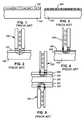
- FIG. 9is a partial side view of a perpendicular write head pole tip region, not to scale, during fabrication of a write head.
- FIG. 10is a partial side view of the perpendicular write head pole tip region of FIG. 9 upon addition of a trailing shield by deposition.
- FIG. 11is a partial side view of the perpendicular write head pole tip region of FIG. 9 upon addition of a trailing shield by plating.
- FIG. 12is a partial side view of the perpendicular write head pole tip region of FIG. 11 upon addition of a return layer.
- FIG. 6there is shown a disk drive 600 embodying the present invention.
- at least one rotatable magnetic disk 612is supported on a spindle 614 and rotated by a disk drive motor 618 .
- the magnetic recording on each diskis in the form of an annular pattern of concentric data tracks (not shown) on the disk 612 .
- At least one slider 613is positioned near the disk 612 , each slider 613 supporting one or more magnetic read/write heads 621 . More information regarding such heads 621 will be set forth hereinafter during reference to the remaining FIGS.
- Slide 613is moved radially in and out over disk surface 622 so that heads 621 may access different tracks of the disk where desired data are recorded.
- Each slider 613is attached to an actuator arm 619 by way of a suspension 615 .
- the suspension 615provides a slight spring force which biased slider 613 against the disk surface 622 .
- Each actuator arm 619is attached to an actuator means 627 .
- the actuator means 627 as shown in FIG. 3may be voice coil motor (VCM).
- VCMcomprises a coil movable within a fixed magnetic field, the direction and speed of the coil movements being controlled by the motor current signals supplied by controller 629 .
- the rotation of disk 612generates an air bearing between slider 613 and disk surface 622 which exerts an upward force or lift on the slider.
- the air bearingthus counter-balances the slight spring force of suspension 615 and supports slider 613 off and slightly above the disk surface by a small, substantially constant spacing during normal operation.
- control unit 629The various components of the disk storage system are controlled in operation by control signals generated by control unit 629 , such as access control signals and internal clock signals.
- control unit 629comprises logic control circuits, storage means and a microprocessor.
- the control unit 629generates control signals to control various system operations such as drive motor controls signals on line 623 and head position and seek control signals on line 628 .
- the control signals on line 628provide the desired current profiles to optimally move and position slider 613 to the desired data track on disk 612 .
- Read and write signalsare communicated to and from read/write heads 621 by way of recording channel 625 .
- disk storage systemmay contain a large number of disks and actuators, and each actuator may support a number of sliders.
- FIG. 7illustrates schematically the orientation of magnetic impulses off-normal to an imaginary plane oriented perpendicular to the surface of the recording medium, generally in the manner provided for by the present invention.
- the off-normal fluxis created by the combination of a pole 702 and a trailing shield 703 .
- the mediumincludes an under layer 704 of a material having a high magnetic permeability, preferably greater than 100, such as a permalloy material.
- This under layer 704is then provided with an overlying coating 706 which contains a magnetic material preferably having a coercivity substantially greater than the under layer 704 .
- Both of these layers 704 and 706are shown applied to a suitable substrate 708 , which may desirably be an aluminum alloy disc, although other material such as glass may also be used.
- Magnetic lines of flux extending between the poles 702 , 710 of the recording head 700loop into and out of the outer surface of the recording medium coating 706 with the high permeability under layer 704 of the recording medium causing the lines of flux to pass through the coating 706 in a direction at an angle to an imaginary plane perpendicular to the surface of the medium to record information in the magnetically hard coating 706 of the medium in the form of magnetic impulses having their axes of magnetization generally perpendicular to the surface of the medium.
- the fluxis channeled by the soft underlying coating 704 back to the return layer (P 1 ) 710 of the head 700 .
- FIG. 8illustrates a perpendicular read/write head structure 800 having a trailing shield 802 according to one embodiment. Methods for forming the trailing shield will be discussed subsequently.
- a residual masking structure 804can be created and left in the head 800 to allow for the information of the trailing shield and for the subsequent fabrication steps to build the remainder of the write head 806 . Note that it is desirable to leave the masking structure 804 in the head 800 to protect the write gap and pole tip, to protect them from subsequent processing (e.g., copper coils).
- a read head 808is formed first.
- the read headincludes a first shield layer 810 , a sensor 812 , and a second shield layer 814 .
- a pole 816is formed above the first shield layer 810 .
- a coil structure 818 and insulation layers 820 , 880are formed above the first pole layer 816 .
- a flux shaping layer 824is formed above the pole layer 816 .
- a probe pole tip 826is formed above the flux shaping layer 824 and extends to the air bearing surface (ABS) 888 of the head 800 .
- the shaping layer 824magnetically connects the magnetic flux from the back gap 884 to the pole tip 826 .
- the probe pole tip 826directs the flux into the media to perform the write function.
- the fluxreturns through the media to the return pole 890 .
- the pole tip 826is preferably a ferromagnetic structure with a high magnetostriction, typically CoFe, NiFe, or laminated layers (CoFe, nonmagnetic layer, CoFe, nonmagnetic layer, etc.)
- a nonmagnetic gap layer 828is formed above the probe pole tip 826 .
- Exemplary materials for the gap layer 828are alumina or a nonmagnetic metal such as Rh, Ru, etc.
- Rh, Rua nonmagnetic metal
- a masking structure 804 of conventional materialssuch as a photoresist (oxide, nitride, silanated resist, etc.) is formed above the gap layer 828 .
- the trailing shield 802is formed above the gap layer 828 and the masking structure 804 .
- the trailing shield 802is preferably constructed of a soft magnetic material, and should have a high magnetic moment.
- a preferred material for the trailing shield 802is NiFe and alloys thereof.
- the throat height of the trailing shield 802is defined between the masking structure 804 and the ABS.
- the trailing shield 802should have a throat height that is much less than the distance from the shaping layer 824 to the ABS end of the pole tip 826 .
- the throat height of the trailing shield 802is less than about 80%, and more preferably, less than about 60% of the distance from the shaping layer 824 to the ABS end of the pole tip 826 .
- the thickness of the gap layer 828 between the pole tip 826 and the trailing shield 802is preferably roughly equal to the distance from the pole tip 826 to the soft underlayer of the media, though a ratio of the gap layer 828 thickness to the distance from the pole tip 826 to the soft underlayer of the media can be in the range of about 1:2 to about 2:1.
- An illustrative thickness of the gap layer 828can be about 35 nm or less, but will scale with the dimensions of the pole tip 826 , the dimensions being the track width and thickness of probe pole tip 826 .
- the thickness of the gap layer 828will be less than about 50 nm for a track width on the order of about 0.1 microns or less.
- trailing shield 802bends the magnetic flux lines. More particularly, the magnetic field that comes out of the probe pole tip 826 enters the media at an off-normal angle, which may help write more stable bits in the media.
- FIG. 9An outline of a perpendicular write head pole tip 826 region is shown in FIG. 9 , where the separation of the trailing shield 802 and the pole tip 826 is a gap of non-magnetic material.
- a masking structureis formed above the write gap 828 .
- the height of masking structure (HM)is preferably substantially greater than the distance from the shaping layer 824 to the ABS. For instance, the height can be greater than about 125% the distance from the shaping layer 824 to the ABS.
- the reason for the tall height of the masking structure 804is to prevent leakage of the flux into the trailing shield 802 before it reaches the ABS.
- a preferred height of the masking structure 804is about 0.5 microns or more.
- the masking structure 804is preferably formed of a material that can remain in the head, such as an oxide, nitride, silanated resist (Si-containing resist) such as HSQ (hydrosilsesquioxide), etc.
- the maskis patterned and possibly shaped via reactive ion etching (RIE).
- the trailing shield 802 of NiFe other ferromagnetic materialis deposited over and/or around the mask. For instance, if the trailing shield 802 is a sputter deposited magnetic material, the trailing shield 802 will encapsulate the masking structure 804 .
- FIGS. 11-12depict a method of forming a trailing shield 802 by plating.
- the gap layer 828 between the pole tip 826 and trailing shield 802must be nonmagnetic, e.g., of alumina or some metal such as Rh, Ru, etc. Rh and Ru are preferred because they are very conductive, and the oxide of Ru is electrically conductive so it can be plated on.
- a masking structure 804is formed, preferably of a material that can remain in the head. See FIG. 10 .
- the structureis then placed in a plating solution and the trailing shield 802 is formed by plating, resulting in the structure shown in FIG. 11 .
- the trailing shield 802may be overplated, such that it “mushrooms” over the edge of the masking structure 804 . While the trailing shield 802 can be allowed to float, it is preferable to ferromagnetically connect the plated trailing shield 802 structure to the rest of the head. As shown in FIG.
- the trailing shield 802is stitched to the head by a photolithographic lift off or, as shown, forming a return layer 1302 by plating more NiFe to the plated structure.
- the return layer 1302extends back to the return pole 816 . Note that the location and shape of the return layer 1302 can vary, but it is preferably stitched to the return pole 816 .
- One advantage provided by the present inventionincludes allowing trailing shield edge definition to be defined with a thin resist process. Another advantage is that the edge of shield thickness is determined by the thickness of the transfer material. Yet another advantage is that the processes disclosed herein allow a thin trailing shield 802 to be fabricated without damaging the pole tip 826 . A further advantage is that the masking material is not present at the ABS surface.
Landscapes
- Engineering & Computer Science (AREA)
- Manufacturing & Machinery (AREA)
- Magnetic Heads (AREA)
Abstract
Description
Claims (11)
Priority Applications (1)
| Application Number | Priority Date | Filing Date | Title |
|---|---|---|---|
| US11/678,856US7841067B2 (en) | 2003-09-26 | 2007-02-26 | Method for manufacturing a trailing shield structure for a perpendicular magnetic write head |
Applications Claiming Priority (2)
| Application Number | Priority Date | Filing Date | Title |
|---|---|---|---|
| US10/672,094US7199973B2 (en) | 2003-09-26 | 2003-09-26 | Perpendicular magnetic recording head with trailing shield throat height less than shaping layer distance from ABS |
| US11/678,856US7841067B2 (en) | 2003-09-26 | 2007-02-26 | Method for manufacturing a trailing shield structure for a perpendicular magnetic write head |
Related Parent Applications (1)
| Application Number | Title | Priority Date | Filing Date |
|---|---|---|---|
| US10/672,094DivisionUS7199973B2 (en) | 2003-09-26 | 2003-09-26 | Perpendicular magnetic recording head with trailing shield throat height less than shaping layer distance from ABS |
Publications (2)
| Publication Number | Publication Date |
|---|---|
| US20070137027A1 US20070137027A1 (en) | 2007-06-21 |
| US7841067B2true US7841067B2 (en) | 2010-11-30 |
Family
ID=34376271
Family Applications (2)
| Application Number | Title | Priority Date | Filing Date |
|---|---|---|---|
| US10/672,094Expired - LifetimeUS7199973B2 (en) | 2003-09-26 | 2003-09-26 | Perpendicular magnetic recording head with trailing shield throat height less than shaping layer distance from ABS |
| US11/678,856Expired - Fee RelatedUS7841067B2 (en) | 2003-09-26 | 2007-02-26 | Method for manufacturing a trailing shield structure for a perpendicular magnetic write head |
Family Applications Before (1)
| Application Number | Title | Priority Date | Filing Date |
|---|---|---|---|
| US10/672,094Expired - LifetimeUS7199973B2 (en) | 2003-09-26 | 2003-09-26 | Perpendicular magnetic recording head with trailing shield throat height less than shaping layer distance from ABS |
Country Status (1)
| Country | Link |
|---|---|
| US (2) | US7199973B2 (en) |
Families Citing this family (21)
| Publication number | Priority date | Publication date | Assignee | Title |
|---|---|---|---|---|
| JP4116913B2 (en)* | 2003-03-26 | 2008-07-09 | Tdk株式会社 | Perpendicular magnetic recording head and magnetic recording apparatus |
| JP4260002B2 (en)* | 2003-12-24 | 2009-04-30 | ヒタチグローバルストレージテクノロジーズネザーランドビーブイ | Magnetic head, manufacturing method thereof, and magnetic recording / reproducing apparatus |
| US7221539B2 (en)* | 2004-03-31 | 2007-05-22 | Headway Technologies, Inc. | Stitched shielded pole structure for a perpendicular magnetic recording write head |
| KR100718127B1 (en)* | 2005-04-28 | 2007-05-14 | 삼성전자주식회사 | Vertical magnetic recording head |
| JP2007122840A (en)* | 2005-10-31 | 2007-05-17 | Toshiba Corp | Perpendicular magnetic recording device |
| US7593183B2 (en)* | 2006-04-25 | 2009-09-22 | Hitachi Global Storage Technologies Netherlands B.V. | Magnetic write head design for reducing temperature induced protrusion |
| US7748104B2 (en)* | 2006-04-25 | 2010-07-06 | Hitachi Global Storage Technologies Netherlands B.V. | Structure and method for reduced corrosion of auxiliary poles during the fabrication of perpendicular write heads |
| US7712206B2 (en)* | 2006-05-22 | 2010-05-11 | Hitachi Global Storage Technologies Netherlands B.V. | Method for manufacturing a magnetic write head having a trailing shield with an accurately controlled trailing shield gap thickness |
| US7835111B2 (en)* | 2007-02-15 | 2010-11-16 | Hitachi Global Storage Technologies Netherlands B.V. | Magnetic write head with upper return pole optimization for reduced trailing shield protrusion |
| US8325440B2 (en)* | 2007-03-26 | 2012-12-04 | Tdk Corporation | Magnetic head including a pole layer and an antireflection film sandwiched by two shields |
| US7995307B2 (en)* | 2007-07-19 | 2011-08-09 | Hitachi Global Storage Technologies Netherlands B.V. | Perpendicular magnetic recording write head with trailing shield having throat height defined by electroplated nonmagnetic pad layer and method for making the head |
| US8472286B2 (en)* | 2008-12-31 | 2013-06-25 | HGST Netherlands B.V. | Near field transducer having main body and wings extending therefrom and only electrically coupled thereby |
| US8792206B2 (en)* | 2009-05-18 | 2014-07-29 | Seagate Technology Llc | Method and apparatus for controlled front shield thickness for perpendicular writer |
| US8349197B2 (en)* | 2009-11-20 | 2013-01-08 | Hitachi Global Storage Technologies Netherlands B.V. | Method for manufacturing a perpendicular magnetic write head having a tapered write pole and non-magnetic bump structure |
| JP2012022731A (en)* | 2010-07-12 | 2012-02-02 | Hitachi Ltd | Magnetic head slider and magnetic disk device using the same |
| US8797686B1 (en) | 2010-12-23 | 2014-08-05 | Western Digital (Fremont), Llc | Magnetic recording transducer with short effective throat height and method of fabrication |
| US9053715B1 (en) | 2011-03-29 | 2015-06-09 | Western Digital (Fremont), LLC. | System for providing a transducer having a split main pole |
| US8587900B2 (en) | 2011-05-24 | 2013-11-19 | HGST Netherlands B.V. | Radiator-cooled nanowire-based write assist |
| US8628672B1 (en) | 2012-06-27 | 2014-01-14 | Western Digital (Fremont), Llc | Process for manufacturing a perpendicular magnetic recording writer pole with nonmagnetic bevel |
| US9042051B2 (en) | 2013-08-15 | 2015-05-26 | Western Digital (Fremont), Llc | Gradient write gap for perpendicular magnetic recording writer |
| US9082423B1 (en) | 2013-12-18 | 2015-07-14 | Western Digital (Fremont), Llc | Magnetic recording write transducer having an improved trailing surface profile |
Citations (9)
| Publication number | Priority date | Publication date | Assignee | Title |
|---|---|---|---|---|
| EP0279536A2 (en)* | 1987-02-17 | 1988-08-24 | Seagate Technology International | Magnetoresistive head and process for its manufacture |
| US5285340A (en)* | 1992-02-28 | 1994-02-08 | International Business Machines Corporation | Thin film magnetic head with conformable pole tips |
| US5932082A (en)* | 1996-03-29 | 1999-08-03 | The University Of Tulsa | Electroplating bath for nickel-iron alloys and method |
| US5986856A (en)* | 1997-05-13 | 1999-11-16 | Segate Technology, Inc. | Magnetoresistive sensor with improved stability |
| US6018862A (en)* | 1997-10-07 | 2000-02-01 | Seagate Technology, Inc. | Thin-film magnetic recording head using a plated metal gap layer |
| US6054023A (en)* | 1997-12-22 | 2000-04-25 | International Business Machines Corporation | Method of making inverted merged MR head with track width defining first pole tip component constructed on a side wall |
| US6154345A (en)* | 1997-04-07 | 2000-11-28 | Nec Corporation | Magnetoresistive effect composite head |
| US6278580B1 (en)* | 1998-10-15 | 2001-08-21 | Tdk Corporation | Composite type thin film magnetic head that includes a pole chip and a top pole and an insulating layer that acts as an etching stopper during anisotropic etching |
| US6345435B1 (en)* | 1999-11-22 | 2002-02-12 | Headway Technologies, Inc. | Method to make laminated yoke for high data rate giant magneto-resistive head |
Family Cites Families (21)
| Publication number | Priority date | Publication date | Assignee | Title |
|---|---|---|---|---|
| JPS5971115A (en)* | 1982-10-15 | 1984-04-21 | Hitachi Ltd | Thin film head for vertical magnetic recording and reproduction |
| JPH0693289B2 (en)* | 1986-07-22 | 1994-11-16 | アルプス電気株式会社 | Thin film magnetic head for perpendicular magnetic recording |
| JPS63195816A (en)* | 1987-02-09 | 1988-08-12 | Sumitomo Special Metals Co Ltd | Production of thin film head |
| US4839761A (en)* | 1987-07-31 | 1989-06-13 | Seagate Technology, Inc. | Magnetic head for perpendicular magnetic recording system |
| EP0311854A1 (en)* | 1987-10-16 | 1989-04-19 | Siemens Aktiengesellschaft | Layered structure thin-film magnetic head for perpendicular magnetization |
| US5075956A (en)* | 1988-03-16 | 1991-12-31 | Digital Equipment Corporation | Method of making recording heads with side shields |
| US5155646A (en)* | 1989-07-26 | 1992-10-13 | Victor Company Of Japan, Ltd. | Multiple layered thin-film magnetic head for magnetic recording and reproducing apparatus |
| US5872693A (en)* | 1993-08-10 | 1999-02-16 | Kabushiki Kaisha Toshiba | Thin-film magnetic head having a portion of the upper magnetic core coplanar with a portion of the lower magnetic core |
| US5452164A (en)* | 1994-02-08 | 1995-09-19 | International Business Machines Corporation | Thin film magnetic write head |
| JP2784431B2 (en)* | 1994-04-19 | 1998-08-06 | インターナショナル・ビジネス・マシーンズ・コーポレイション | Thin-film magnetic write head, read / write magnetic head, disk drive, and method of manufacturing thin-film magnetic write head |
| US5805391A (en)* | 1996-10-28 | 1998-09-08 | International Business Machines Corporation | Write head with recessed stitched yoke on a planar portion of an insulation layer defining zero throat height |
| US5831801A (en)* | 1997-01-21 | 1998-11-03 | Yamaha Corporation | Thin film magnetic head with special pole configuration |
| JPH11288503A (en)* | 1998-04-02 | 1999-10-19 | Tdk Corp | Thin-film magnetic head and its production |
| US6055138A (en)* | 1998-05-06 | 2000-04-25 | Read-Rite Corporation | Thin film pedestal pole tips write head having narrower lower pedestal pole tip |
| US6226149B1 (en)* | 1998-12-15 | 2001-05-01 | International Business Machines Corporation | Planar stitched write head having write coil insulated with inorganic insulation |
| US6594112B1 (en)* | 2000-01-05 | 2003-07-15 | Seagate Technology Llc | Magnetic recording head with a precision throatheight-defining structure |
| JP2002123904A (en)* | 2000-10-13 | 2002-04-26 | Tdk Corp | Thin film magnetic head and manufacturing method thereof |
| JP2002123910A (en)* | 2000-10-16 | 2002-04-26 | Alps Electric Co Ltd | Thin-film magnetic head, and its manufacturing method |
| JP2003036503A (en)* | 2001-07-24 | 2003-02-07 | Hitachi Ltd | Magnetic head for perpendicular recording and magnetic disk drive equipped with the same |
| JP2003085709A (en)* | 2001-09-10 | 2003-03-20 | Hitachi Ltd | Thin-film magnetic head, method of manufacturing the same, and magnetic disk drive |
| US6724572B1 (en)* | 2002-02-28 | 2004-04-20 | Western Digital, Inc. | Inductive transducer with recessed leading pole layer |
- 2003
- 2003-09-26USUS10/672,094patent/US7199973B2/ennot_activeExpired - Lifetime
- 2007
- 2007-02-26USUS11/678,856patent/US7841067B2/ennot_activeExpired - Fee Related
Patent Citations (9)
| Publication number | Priority date | Publication date | Assignee | Title |
|---|---|---|---|---|
| EP0279536A2 (en)* | 1987-02-17 | 1988-08-24 | Seagate Technology International | Magnetoresistive head and process for its manufacture |
| US5285340A (en)* | 1992-02-28 | 1994-02-08 | International Business Machines Corporation | Thin film magnetic head with conformable pole tips |
| US5932082A (en)* | 1996-03-29 | 1999-08-03 | The University Of Tulsa | Electroplating bath for nickel-iron alloys and method |
| US6154345A (en)* | 1997-04-07 | 2000-11-28 | Nec Corporation | Magnetoresistive effect composite head |
| US5986856A (en)* | 1997-05-13 | 1999-11-16 | Segate Technology, Inc. | Magnetoresistive sensor with improved stability |
| US6018862A (en)* | 1997-10-07 | 2000-02-01 | Seagate Technology, Inc. | Thin-film magnetic recording head using a plated metal gap layer |
| US6054023A (en)* | 1997-12-22 | 2000-04-25 | International Business Machines Corporation | Method of making inverted merged MR head with track width defining first pole tip component constructed on a side wall |
| US6278580B1 (en)* | 1998-10-15 | 2001-08-21 | Tdk Corporation | Composite type thin film magnetic head that includes a pole chip and a top pole and an insulating layer that acts as an etching stopper during anisotropic etching |
| US6345435B1 (en)* | 1999-11-22 | 2002-02-12 | Headway Technologies, Inc. | Method to make laminated yoke for high data rate giant magneto-resistive head |
Also Published As
| Publication number | Publication date |
|---|---|
| US7199973B2 (en) | 2007-04-03 |
| US20070137027A1 (en) | 2007-06-21 |
| US20050068673A1 (en) | 2005-03-31 |
Similar Documents
| Publication | Publication Date | Title |
|---|---|---|
| US7841067B2 (en) | Method for manufacturing a trailing shield structure for a perpendicular magnetic write head | |
| US7239478B1 (en) | Write element for perpendicular recording in a data storage system | |
| US7337530B1 (en) | Method for manufacturing a shielded pole magnetic head for perpendicular recording | |
| US7120988B2 (en) | Method for forming a write head having air bearing surface (ABS) | |
| US7388732B2 (en) | Perpendicular recording magnetic head with a write shield megnetically coupled to a first pole piece | |
| US10950257B2 (en) | Process of forming a recessed spin flipping element in the write gap | |
| JP2007172816A (en) | Method of manufacturing perpendicular magnetic recording head and side shield | |
| US7268974B2 (en) | Magnetic write head having a notched yoke structure with a trailing shield and method of making the same | |
| US7436633B2 (en) | Thin-film magnetic head, head gimbal assembly and hard disk system | |
| US10891976B1 (en) | Areal density capability improvement with a main pole skin | |
| US8161627B2 (en) | Method of making a write head lapping guide about aligned to a non-magnetic layer surrounding a write pole | |
| US20020008945A1 (en) | Domain control in shields of a magnetic transducer | |
| JP2006147023A (en) | Thin film magnetic head and manufacturing method thereof | |
| KR0178305B1 (en) | Vertical gap formation method of thin film magnetic transducer | |
| US7359147B2 (en) | Single pole magnetic head having intermediate magnetic layer and tip magnetic layer | |
| US8031434B2 (en) | Hybrid, self aligned magnetic write head with a partially plated pole and method of producing same | |
| US7343667B2 (en) | Methods of making a side-by-side read/write head with a self-aligned trailing shield structure | |
| US7463448B2 (en) | Thin film magnetic head having upper and lower poles and a gap film within a trench | |
| US6989964B2 (en) | Magnetic head having a pole piece with a double pedestal structure | |
| US7086139B2 (en) | Methods of making magnetic write heads using electron beam lithography | |
| JPH11213332A (en) | Thin-film magnetic head and magnetic disk drive | |
| US20250138432A1 (en) | Bottom-Up Main Pole Electroplating For A Magnetic Recording Write Head | |
| US20250140284A1 (en) | Seamless Main Pole Electroplating For A Magnetic Recording Write Head | |
| US6985330B2 (en) | High efficiency side-by-side thin film head utilizing canted shield yokes | |
| US20060209458A1 (en) | Soft magnetic film and thin film magnetic head |
Legal Events
| Date | Code | Title | Description |
|---|---|---|---|
| AS | Assignment | Owner name:HITACHI GLOBAL STORAGE TECHNOLOGIES NETHERLANDS B. Free format text:ASSIGNMENT OF ASSIGNORS INTEREST;ASSIGNOR:LILLE, JEFFREY S.;REEL/FRAME:019120/0840 Effective date:20030924 | |
| FEPP | Fee payment procedure | Free format text:PAYOR NUMBER ASSIGNED (ORIGINAL EVENT CODE: ASPN); ENTITY STATUS OF PATENT OWNER: LARGE ENTITY | |
| AS | Assignment | Owner name:HGST, NETHERLANDS B.V., NETHERLANDS Free format text:CHANGE OF NAME;ASSIGNOR:HGST, NETHERLANDS B.V.;REEL/FRAME:029341/0777 Effective date:20120723 Owner name:HGST NETHERLANDS B.V., NETHERLANDS Free format text:CHANGE OF NAME;ASSIGNOR:HITACHI GLOBAL STORAGE TECHNOLOGIES NETHERLANDS B.V.;REEL/FRAME:029341/0777 Effective date:20120723 | |
| FPAY | Fee payment | Year of fee payment:4 | |
| AS | Assignment | Owner name:WESTERN DIGITAL TECHNOLOGIES, INC., CALIFORNIA Free format text:ASSIGNMENT OF ASSIGNORS INTEREST;ASSIGNOR:HGST NETHERLANDS B.V.;REEL/FRAME:040821/0550 Effective date:20160831 | |
| FEPP | Fee payment procedure | Free format text:MAINTENANCE FEE REMINDER MAILED (ORIGINAL EVENT CODE: REM.) | |
| LAPS | Lapse for failure to pay maintenance fees | Free format text:PATENT EXPIRED FOR FAILURE TO PAY MAINTENANCE FEES (ORIGINAL EVENT CODE: EXP.); ENTITY STATUS OF PATENT OWNER: LARGE ENTITY | |
| STCH | Information on status: patent discontinuation | Free format text:PATENT EXPIRED DUE TO NONPAYMENT OF MAINTENANCE FEES UNDER 37 CFR 1.362 | |
| FP | Lapsed due to failure to pay maintenance fee | Effective date:20181130 |