US7840989B2 - Apparatus and method for extending a cable modem data service over wireless links - Google Patents
Apparatus and method for extending a cable modem data service over wireless linksDownload PDFInfo
- Publication number
- US7840989B2 US7840989B2US11/154,105US15410505AUS7840989B2US 7840989 B2US7840989 B2US 7840989B2US 15410505 AUS15410505 AUS 15410505AUS 7840989 B2US7840989 B2US 7840989B2
- Authority
- US
- United States
- Prior art keywords
- frequency
- upstream
- wireless
- ghz
- cable
- Prior art date
- Legal status (The legal status is an assumption and is not a legal conclusion. Google has not performed a legal analysis and makes no representation as to the accuracy of the status listed.)
- Expired - Fee Related, expires
Links
Images


Classifications
- H—ELECTRICITY
- H04—ELECTRIC COMMUNICATION TECHNIQUE
- H04L—TRANSMISSION OF DIGITAL INFORMATION, e.g. TELEGRAPHIC COMMUNICATION
- H04L12/00—Data switching networks
- H04L12/28—Data switching networks characterised by path configuration, e.g. LAN [Local Area Networks] or WAN [Wide Area Networks]
- H04L12/2801—Broadband local area networks
- H—ELECTRICITY
- H04—ELECTRIC COMMUNICATION TECHNIQUE
- H04N—PICTORIAL COMMUNICATION, e.g. TELEVISION
- H04N21/00—Selective content distribution, e.g. interactive television or video on demand [VOD]
- H04N21/40—Client devices specifically adapted for the reception of or interaction with content, e.g. set-top-box [STB]; Operations thereof
- H04N21/41—Structure of client; Structure of client peripherals
- H04N21/426—Internal components of the client ; Characteristics thereof
- H04N21/42676—Internal components of the client ; Characteristics thereof for modulating an analogue carrier signal to encode digital information or demodulating it to decode digital information, e.g. ADSL or cable modem
- H—ELECTRICITY
- H04—ELECTRIC COMMUNICATION TECHNIQUE
- H04N—PICTORIAL COMMUNICATION, e.g. TELEVISION
- H04N21/00—Selective content distribution, e.g. interactive television or video on demand [VOD]
- H04N21/60—Network structure or processes for video distribution between server and client or between remote clients; Control signalling between clients, server and network components; Transmission of management data between server and client, e.g. sending from server to client commands for recording incoming content stream; Communication details between server and client
- H04N21/61—Network physical structure; Signal processing
- H04N21/6156—Network physical structure; Signal processing specially adapted to the upstream path of the transmission network
- H04N21/6168—Network physical structure; Signal processing specially adapted to the upstream path of the transmission network involving cable transmission, e.g. using a cable modem
- H—ELECTRICITY
- H04—ELECTRIC COMMUNICATION TECHNIQUE
- H04N—PICTORIAL COMMUNICATION, e.g. TELEVISION
- H04N7/00—Television systems
- H04N7/16—Analogue secrecy systems; Analogue subscription systems
- H04N7/173—Analogue secrecy systems; Analogue subscription systems with two-way working, e.g. subscriber sending a programme selection signal
- H04N7/17309—Transmission or handling of upstream communications
- H—ELECTRICITY
- H04—ELECTRIC COMMUNICATION TECHNIQUE
- H04N—PICTORIAL COMMUNICATION, e.g. TELEVISION
- H04N7/00—Television systems
- H04N7/10—Adaptations for transmission by electrical cable
- H04N7/102—Circuits therefor, e.g. noise reducers, equalisers, amplifiers
- H04N7/104—Switchers or splitters
Definitions
- the inventionrelates generally to providing of downstream and upstream data connectivity. More specifically, the invention relates to an interface that allows the extension of a cable modem data service over wireless links.
- CATVcable television
- the delivery of data using the cable television (CATV) systemhas become common in residential areas where CATV is commonly available.
- the dataare delivered both downstream and upstream using available channels and/or frequencies.
- the end usercan connect to such systems through a cable modem that is capable of delivering the downstream data respective of a specific user to that user, as well as sending upstream data sent from the user and that are intended to reach another node of the system.
- FIG. 1is a diagram showing the distribution of CATV to a residential area.
- Clientsuse a cable modem to have access to downstream data and to transfer data upstream. If the CATV operator wants to provide a service to clients in the shopping mall, a distribution coax cable must be laid. This includes a significant cost.
- MMDSMultipoint Microwave Distribution System
- the MMDS wireless cableuses 6 MHZ television channels for upstream and downstream transmission. These channels are relatively closely spaced in frequency. Because the channels are so closely spaced in frequency, a diplexer is required at each subscriber location to separate the upstream transmission path and the downstream receive path. Thus, the processing equipment required, including the diplexer, is relatively expensive and cumbersome. Also, the up to two 6 MHZ channels which may be allocated to the reverse direction are less than the full upstream capacity of DOCSIS. This is a significant bandwidth limitation. In addition, because the MMDS channels are licensed, the ISP must go to the expense of purchasing or leasing a license that could cost in the millions of dollars.
- U-NII band 15.15 to 5.25 GHz
- U-NII band 25.25 to 5.35 GHz
- U-NII band 35.825 GHz
- the U-NII bandsare designated for wideband, high-data-rate digital communications. They are also license-free i.e. no license is required to operate on the U-NII bands.
- the downstreammay use a single down conversion in the customer premises equipment (CPE) prior to the cable modem, with a separate local oscillator and phase locked loop (PLL).
- CPEcustomer premises equipment
- PLLphase locked loop
- the CPE upstreamrequires a dual conversion architecture with two additional local oscillators and PLLs.
- additional filter stagesare required.
- an individual channel conversionis employed for the upstream, which then also requires PLL programming to adjust for the changing cable modem upstream output frequency.
- the prior artuses a high-pass/low-pass filter combination, with multiple circuit elements. This results in high complexity and fabrication difficulty when used in conjunction with a flat panel antenna.
- a wireless hub transceiveris connected to a distribution coax cable of a data-over-cable system based system.
- the downstream dataare transferred over a wireless link to a remote subscriber radio frequency (RF) unit connected to a cable modem that provides the downstream data to the subscriber.
- RFradio frequency
- upstream dataare sent from the subscriber cable modem over the wireless link to the wireless hub transceiver where such data are inserted back to the distribution coax cable.
- FIG. 1is a schematic diagram showing distribution of CATV coax cables in a residential area (prior art);
- FIG. 2is a schematic diagram showing distribution of CATV coax cables in a residential area with a wireless extension in accordance with the disclosed invention
- FIG. 3is a schematic block diagram showing an architecture an exemplary wireless cable extension hub (cable side) connected to a distribution coax cable of a CATV;
- FIG. 4is a schematic block diagram showing an exemplary 5.7/5.8 GHz Split-Band CPE architecture in accordance with the disclosed invention
- FIG. 5is a flowchart showing the downstream flow of data in accordance with the disclosed invention.
- FIG. 6is a flowchart showing the upstream flow of data in accordance with the disclosed invention.
- FIG. 7is a flowchart showing the determination of the upstream gain (g us ).
- FIG. 8is a frequency map showing upstream and downstream frequencies in accordance with the disclosed invention.
- FIG. 1a schematic diagram 100 showing the distribution of CATV over coax cable 115 to residences 110 .
- Some of the residences 110may be able to communicate data over the cable system 115 by connecting to a cable modem 117 .
- cable distributionis limited to the residential area itself.
- Commercial areas, such as a shopping mall 120may be located several hundred or thousands of feet away from the end of the distribution area.
- the investment in laying physical coax cable for distribution purposesmay be prohibitive.
- FIG. 2shows a modified CATV distribution scheme using wireless communication to deliver data to shopping mall 120 .
- a splitter unit (SU) 310is connected to the distribution coax cable 115 .
- the SU 310delivers downstream data to a wireless hub transceiver (WHT) 300 and the WHT 300 provides the SU 310 with upstream data.
- the WHT 300uses an antenna 230 to communicate with another antenna 240 , as explained in more detail below.
- a receiving unit comprised of an antenna 240 and a subscriber radio frequency unit (SRFU) 242is described in detail in U.S. Pat. No. 6,785,150, titled System and Method for Wireless Cable Data Transmission, assigned to common assignee and which is hereby incorporated by reference for all that it contains.
- SRFUsubscriber radio frequency unit
- the SRFU 242is also connected to a cable modem therefore enabling a subscriber in mall 120 to receive data communication through data-over-cable communication, for example through the extension of the DOCSIS cable modem service over a wireless link.
- the inventioncan be easily adapted to comply with other data over cable standards.
- DOCSISDOCSIS
- a more detailed description of an exemplary SRFU 242is provided below.
- a person skilled in the artmay easily modify such a receiving unit to support a 64 or 256 quadrature amplitude modulation (QAM).
- the SU 310provides upstream and downstream connectivity to the WHT 300 .
- the SU 310also provides the AC power required for the operation of the WHT 300 .
- a more detailed description of the WHT 300is provided below.
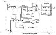
- FIG. 3shows an exemplary and non-limiting architecture of a wireless cable extension hub (cable side) implemented in accordance with the disclosed invention and, in particular, shows a detailed block diagram of a WHT 300 connected through a SU 310 to a distribution coax cable 115 .
- the WHT 300comprises a splitter 320 , an embedded cable modem controller 340 , a downstream channel unit 350 , an automatic gain control 360 , a programmable gain 310 , an upstream channel unit 380 , an up-converter transmitter unit 390 , and a down-converter receiver unit 395 , both of which are connected to an antenna 230 .
- a DC power unit 330is optionally connected to a splitter 320 if it is possible to provide AC power from the distribution coax cable 115 .
- FIG. 8also shows frequency bands that are used for the purpose of transmitting the upstream and downstream data.
- upstream dataare transmitted in a frequency band 810 between 5.725 GHz and 5.770 GHz.
- the downstream dataare transmitted over a frequency band 820 between 5.810 GHz and 5.850 GHz.
- the upper frequencyis 5.875 GHz.
- DOCSISis only one example of a data-over-cable transmission standard, though reference hereinafter is made to DOCSIS.
- the splitter 320is responsible for handling the signal communication with the SU 310 , operating in conjunction with the embedded cable modem controller 340 , as well as delivering to and receiving from downstream and upstream signals for the downstream channel unit 350 and upstream channel unit 380 , respectively.
- the splitter 320is also responsible for delivering AC power to the DC power unit 330 that provides the DC power required by the WHT 300 for its operation.
- Operation of the WHT 300is performed under the control of the embedded cable modem controller 340 .
- Various control signalsare delivered to components of WHT 300 .
- the downstream channel unit 350is controlled as to the center DOCSIS downstream frequency (f ds ) for wireless operation.
- a bandwidth of 6 MHzis used which is the standard bandwidth used in CATV systems.
- the upstream channel unitis controlled for both the center DOCSIS upstream frequency (f us ) for wireless operation, as well as for the upstream DOCSIS bandwidth (bw us ) which is selective at doubling steps starting from 200 KHz up to 3.2 MHZ, or 6.4 MHz in the case of DOCSIS 2.0.
- DOCSIS carrierssupport frequencies of 50-860 MHz for downstream communication, of which 75-120 MHz are used in accordance with the disclosed invention; and 5-48 MHz for upstream communication, of which 5-42 MHz are used in accordance with the disclosed invention.
- the embedded cable modem controller 340also controls the down-converter 395 as to the selection of the upstream carrier frequencies in the range of 5.725 to 5.770 GHz. These frequencies are selected such that they are in the license frequency spectrum.
- the controller 340also controls the up-converter 390 as for the operation of the cable frequency air map, i.e. the conversion necessary from the cable frequency to the air frequency for the wireless downstream transmission. These frequencies are selected such that they are in the license free frequency spectrum.
- the embedded cable modem controller 340determines the DOCSIS carrier frequency mapping from cable to air.
- An automatic gain control (AGC) 360 connected between downstream channel unit 350 and the up-converter transmitter unit 390ensures that the correct level of gain is used. This is particularly important because as the CATV signal received through distribution coax cable 115 may vary considerably throughout its distribution area. However, for the purpose of quality transmission it is essential to maintain required levels of signal.
- a programmable gain unit 370is connected between the down-converter receiver unit 395 and this upstream channel unit 380 .
- the gainis controlled by an embedded cable modem controller 395 that provides the upstream gain (g us ) parameter.
- the value for gcan be determined at installation or, in another embodiment, it can be adjusted from time-to-time automatically through test sequences initiated by embedded cable modem controller 395 .
- the DOCSIS standardrequires that all cable modems adjust their upstream power level in a long AGC loop commanded from the cable modem termination system (CMTS) equipment.
- the range of adjustmentis approximately 50 dB to account for large variations in the cable plant upstream system gain and level.
- the inventionuses the setting of the embedded CM controller upstream level to adjust the gain of the path g us for the wireless subscriber unit. By removing the cable plant level variation in the wireless return path, the subscriber cable modem gain variation is available to compensate for air link radio frequency (RF) level variations.
- RFradio frequency
- the CMTS in the headendcommands the subscriber modem level in the same manner as got wired modems, but the actual gain compensation is for both the wired modem and the wireless link.
- the embedded CM controller 340periodically computes the correct setting of g us such that the upstream signal level from each of subscriber modems 244 , as commanded by the CMTS during its normal long AGC loop operation, remains within the optimum operating range of the subscriber modem, and is presented at the nominal level for entry into the cable system upstream path at the WHT 300 splitter 320 .
- This computation and correction to g usnormally takes place less frequently than the normal CMTS/subscriber modem long AGC loop correction.
- the CM controller 340monitors as described above, and then adjusts g us for each transmission for each subscriber modem 244 in very small steps so the CMTS can command subscriber modem 244 to make normal gain changes without being aware that g us is also being adjusted.
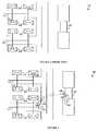
- FIG. 4shows a 5.7/5.8 GHz Split-Band CPE architecture implemented in accordance with the disclosed invention.
- the up-converter 390is connected to the upstream portion of an antenna 240 , i.e. antenna 240 -up, that is capable of transmitting wireless signals at a frequency range of 5.725 to 5.770 GHz.
- the down-converter 395is connected to the downstream portion of antenna 240 , i.e. antenna 240 -down, capable of receiving wireless signals at a frequency range of 5.810 to 5.875 GHz.
- a single PLL 430is used to drive a local oscillator (LO) 440 that in turn, drives both the upstream and downstream converters 390 and 395 respectively.
- the LO 440generates a signal at a frequency of 2.86 GHz which is delivered to the buffers 411 and 421 , each of which drives its respective converter.
- the LO frequencyis doubled using the frequency doublers 414 and 424 .
- the phase shifters 412 , 413 , 422 , and 423maintain a phase shift of ninety degrees between the two paths of the signal.
- the harmonic mixers 416 and 417are used to mix the signal and the doubled LO frequency in the upstream path, and the harmonic mixers 426 and 427 perform the function for the downstream path.
- a summation unit 415sums up the signals from the two internal paths which are phase shifted in the upstream path.
- the signal received from antenna 240 -downis split between the two paths of the down converter 395 .
- the frequencyis actually synthesized and fed to the LO port of the harmonic mixers at one-half the frequency (2.860 GHz), which allows the 5.720 GHz, to be rejected from the upstream output path, and therefore removed from the signal transmitted on the upstream. While not required, this allows the use of the same LO 440 and PLL 430 for the downstream receiver block 395 .
- the cable modem upstreamprovides frequencies in the range of 5-50 MHz (end points) that are mapped from 5.725 through 5.770 GHz in the stated frequency example.
- the antenna 240is preferably a puck-style bandstop filter that is capable of separating the 5.7 GHz and 5.8 GHz upstream and downstream signals at the CPE antenna 240 . This reduces the number of components required to two microwave pucks, which are adhered under a shield and tuned directly onto a CPE flat panel printed circuit board (PCB) antenna array.
- PCBprinted circuit board
- FIG. 5is an exemplary flowchart 500 for showing the sending of data for downstream transmission in a CATV data distribution system having a wireless point of termination.
- trafficis intercepted from a CATV distribution coax cable.
- the signal received in step S 510is amplified as may be required, preferably by using an AGC arrangement.
- the selected DOCSIS downstream channeltypically over a 90-1000 MHz range, employed by the specific CATV provider, is upconverted to a fixed IF frequency, for example 1220 MHz (step S 530 ), then downconverted to a fixed IF frequency, typically 44 MHz (step S 540 ), where the signal is sent to a DOCSIS channel filter (step S 550 ).
- step S 560the DOCSIS cable frequency is upconverted to a RF frequency channel, and in step S 570 it is sent via DOCSIS over the air.
- These frequenciesare selected such that they are in the license free frequency spectrum in the range of 5.725 to 5.875 GHz, or a subset thereof such as 5.810 to 5.875 GHz.
- the embedded cable modem controller 340determines the DOCSIS carrier frequency of the original signal from the cable and automatically tunes the frequency synthesizer for the first conversion steps. The disclosed sequence of steps is repeated every time the selected DOCSIS downstream frequency changes because the embedded cable modem automatically tracks this change, and the new tuning information is thereby sent.
- the air mapensures that the CM receives its downstream signal aligned with a standard CATV channel plan, e.g. the North American CATV plan. It such an embodiment it is required to maintain the air map at integer multiples of 6 MHz to adhere with the standard channel spacing. Hence, a conversion is performed from any DOCSIS channel from 90-1,000 MHz to any, for example, 5.8 GHz channel.
- air frequency mappingmay be used.
- An alternative DOCSIS channel mappingsuch as the 8 MHz system used by Euro-DOCSIS, could also be employed in a similar manner as such outlined. The total number of channels available would be equal to the total RF frequency bandwidth available, divided by the channel bandwidth.
- FIG. 6is a 600 showing the receiving of data for upstream transmission in a CATV data distribution system having a wireless point of termination.
- a return frequencyis selected in the range of 5.725 GHz to 5.770 GHz.
- upstream dataare received from the wireless channel.
- the signalis down converted to the DOSIS cable frequency in step S 630 , specifically in the DOCSIS range of 5 to 50 MHz.
- the gain of the received signalis then adjusted in step S 640 .
- the specific gain g uscan be programmed when the system is put in place in accordance with the specific transmit level characteristics of the embedded CM controller.
- the DOCSIS standardrequires that all cable modems adjust their upstream power level in a long AGC loop commanded from the cable modem termination system (CMTS) equipment.
- the range of adjustmentis approximately 50 dB to account for large variations in the cable plant gain.
- the inventionuses the setting of the embedded CM controller upstream level to adjust the gain of the path g us for the wireless subscriber unit. By removing the cable plant level variation in the wireless return path, the subscriber cable modem gain variation is available to compensate for air link RF level variations.
- the CMTS in the headendcommands the subscriber modem level in the same manner as for wired modems, but the actual gain compensation is for the wireless link.
- the received signalis filtered for the specific DOCSIS channel used for upstream data delivery.
- step S 660the upstream data are injected back to the CATV distribution cable.
- the disclosed sequence of stepsis repeated every time data are transferred upstream to the CATV distribution coax cable 115 using the WHT 300 .
- Step S 630 and step S 640could alternately be performed in reverse order, as long as both steps are performed.
- FIG. 7is a flowchart 700 showing the determination of the upstream gain (g us ).
- a normal DOCSIS cable modem signal acquisition for communications between it and the cable headend CMTS equipmentis performed. This procedure is part of the normal process, whereby the upstream transmit gain is adjusted over a range of approximately 50 dB to deliver a fixed level of signal to the headend CMTS. This compensates for cable plant gain variations.
- the setting for the required upstream gain (g us )is determined as a linear relationship to the embedded CM controller's 340 transmit level.
- the g us determined in step S 720is applied to PGU 370 .
- This sequence of stepsallows for the removal of gain variability of the upstream cable plant for signals received from the WHT 300 .
- the subscriber modem 244 level adjustment rangeautomatically compensates the air RF link level variations using the normal DOCSIS method.
Landscapes
- Engineering & Computer Science (AREA)
- Signal Processing (AREA)
- Multimedia (AREA)
- Computer Networks & Wireless Communication (AREA)
- Two-Way Televisions, Distribution Of Moving Picture Or The Like (AREA)
Abstract
Description
Claims (27)
Priority Applications (1)
| Application Number | Priority Date | Filing Date | Title |
|---|---|---|---|
| US11/154,105US7840989B2 (en) | 2003-06-16 | 2005-06-15 | Apparatus and method for extending a cable modem data service over wireless links |
Applications Claiming Priority (3)
| Application Number | Priority Date | Filing Date | Title |
|---|---|---|---|
| US10/463,483US7596798B2 (en) | 2003-06-16 | 2003-06-16 | Apparatus and method for extending DOCSIS cable modem service over wireless links |
| US64548005P | 2005-01-18 | 2005-01-18 | |
| US11/154,105US7840989B2 (en) | 2003-06-16 | 2005-06-15 | Apparatus and method for extending a cable modem data service over wireless links |
Related Parent Applications (1)
| Application Number | Title | Priority Date | Filing Date |
|---|---|---|---|
| US10/463,483Continuation-In-PartUS7596798B2 (en) | 2003-06-16 | 2003-06-16 | Apparatus and method for extending DOCSIS cable modem service over wireless links |
Publications (2)
| Publication Number | Publication Date |
|---|---|
| US20050235333A1 US20050235333A1 (en) | 2005-10-20 |
| US7840989B2true US7840989B2 (en) | 2010-11-23 |
Family
ID=35097791
Family Applications (1)
| Application Number | Title | Priority Date | Filing Date |
|---|---|---|---|
| US11/154,105Expired - Fee RelatedUS7840989B2 (en) | 2003-06-16 | 2005-06-15 | Apparatus and method for extending a cable modem data service over wireless links |
Country Status (1)
| Country | Link |
|---|---|
| US (1) | US7840989B2 (en) |
Cited By (2)
| Publication number | Priority date | Publication date | Assignee | Title |
|---|---|---|---|---|
| US20090247076A1 (en)* | 2006-07-21 | 2009-10-01 | Allan Bartlett | Radio frequency signal distribution using data cable system |
| US20110221572A1 (en)* | 2010-03-11 | 2011-09-15 | Checkpoint Systems, Inc. | Rfid converter module |
Families Citing this family (17)
| Publication number | Priority date | Publication date | Assignee | Title |
|---|---|---|---|---|
| US6842459B1 (en) | 2000-04-19 | 2005-01-11 | Serconet Ltd. | Network combining wired and non-wired segments |
| EP2234394A1 (en) | 2001-10-11 | 2010-09-29 | Mosaid Technologies Incorporated | Coupling device |
| IL152824A (en) | 2002-11-13 | 2012-05-31 | Mosaid Technologies Inc | Addressable outlet and a network using same |
| IL154921A (en) | 2003-03-13 | 2011-02-28 | Mosaid Technologies Inc | Telephone system having multiple distinct sources and accessories therefor |
| US7120413B2 (en)* | 2003-06-22 | 2006-10-10 | Realtek Semiconductor Corp. | Television tuner and method of processing a received RF signal |
| US7180553B2 (en)* | 2003-06-22 | 2007-02-20 | Realtek Semiconductor Corp. | Dual mode television tuner capable of processing both digital and satellite television signals and method thereof |
| US7262815B2 (en)* | 2003-06-22 | 2007-08-28 | Realtek Semiconductor Corp. | Harmonic mixer based television tuner and method of processing a received RF signal |
| IL157787A (en) | 2003-09-07 | 2010-12-30 | Mosaid Technologies Inc | Modular outlet for data communications network |
| US7202916B2 (en)* | 2003-12-15 | 2007-04-10 | Realtek Semiconductor Corp. | Television tuner and method of processing a received RF signal |
| IL159838A0 (en) | 2004-01-13 | 2004-06-20 | Yehuda Binder | Information device |
| IL160417A (en) | 2004-02-16 | 2011-04-28 | Mosaid Technologies Inc | Outlet add-on module |
| US7526248B2 (en)* | 2006-06-06 | 2009-04-28 | Nextwave Broadband, Inc. | Extended wireless communication system and method |
| CN101465656A (en)* | 2008-09-05 | 2009-06-24 | 华为技术有限公司 | Device, method and system for frequency conversion |
| CN101902419B (en)* | 2009-05-27 | 2013-02-13 | 鸿富锦精密工业(深圳)有限公司 | Cable modem and method thereof for keeping communication linkage |
| US20110138440A1 (en)* | 2009-12-03 | 2011-06-09 | John Mezzalingua Associates, Inc. | Downstream output level tilt compensation device between CATV distribution system and CATV user |
| US9247310B2 (en)* | 2012-04-13 | 2016-01-26 | Cisco Technologies, Inc. | DOCSIS out-of-band control signal frequency conversion for legacy set-top boxes |
| US9743383B1 (en)* | 2015-02-24 | 2017-08-22 | The Directv Group, Inc. | Hybrid wireless-wireline communications system and method |
Citations (17)
| Publication number | Priority date | Publication date | Assignee | Title |
|---|---|---|---|---|
| GB2253770A (en) | 1991-01-15 | 1992-09-16 | Rogers Communications Inc | Multichannel radiotelephony system using bidirectional cable T.V. network |
| US5748619A (en) | 1991-10-01 | 1998-05-05 | Meier; Robert C. | Communication network providing wireless and hard-wired dynamic routing |
| US5839052A (en) | 1996-02-08 | 1998-11-17 | Qualcom Incorporated | Method and apparatus for integration of a wireless communication system with a cable television system |
| EP0884915A2 (en) | 1997-06-12 | 1998-12-16 | Radio Communication Systems Limited | Radio PBX for personal communications system |
| US5867763A (en) | 1996-02-08 | 1999-02-02 | Qualcomm Incorporated | Method and apparatus for integration of a wireless communication system with a cable T.V. system |
| US5870134A (en) | 1997-03-04 | 1999-02-09 | Com21, Inc. | CATV network and cable modem system having a wireless return path |
| US5987303A (en) | 1996-05-29 | 1999-11-16 | At&T Corp. | Wireless transmission using fiber link |
| US6259910B1 (en) | 1998-02-13 | 2001-07-10 | Lucent Technologies, Inc. | Wireless telecommunications system architecture supporting block radio technology |
| GB2361145A (en) | 2000-01-27 | 2001-10-10 | Ntl Group Ltd | Data communication system |
| US6324379B1 (en) | 1998-05-28 | 2001-11-27 | California Amplifier, Inc. | Transceiver systems and methods that preserve frequency order when downconverting communication signals and upconverting data signals |
| US6407991B1 (en) | 1993-05-06 | 2002-06-18 | Intermec Ip Corp. | Communication network providing wireless and hard-wired dynamic routing |
| US6415150B1 (en) | 1998-09-11 | 2002-07-02 | Ameritech Corporation | System and method for providing telecommunications service using a wireless link |
| US20020103001A1 (en)* | 2001-02-01 | 2002-08-01 | Haim Weissman | Dynamic capacity allocation of in-building system |
| US20030066088A1 (en) | 1997-12-26 | 2003-04-03 | Samsung Electronics Co., Ltd. | Bidirectional trunk amplifier and cable modem for cable hybrid fiber and coax network which utilizes an upstream pilot signal |
| US20030185163A1 (en)* | 2002-03-27 | 2003-10-02 | Bertonis James G. | System and method for wireless cable data transmission |
| US20030190903A1 (en)* | 2002-07-22 | 2003-10-09 | Envara Ltd. | Zero-loss front end for wireless communication |
| US7505531B1 (en)* | 2000-03-17 | 2009-03-17 | Bridgewave Communications, Inc. | Signal communications system and method for noisy links |
- 2005
- 2005-06-15USUS11/154,105patent/US7840989B2/ennot_activeExpired - Fee Related
Patent Citations (18)
| Publication number | Priority date | Publication date | Assignee | Title |
|---|---|---|---|---|
| GB2253770A (en) | 1991-01-15 | 1992-09-16 | Rogers Communications Inc | Multichannel radiotelephony system using bidirectional cable T.V. network |
| US5748619A (en) | 1991-10-01 | 1998-05-05 | Meier; Robert C. | Communication network providing wireless and hard-wired dynamic routing |
| US6407991B1 (en) | 1993-05-06 | 2002-06-18 | Intermec Ip Corp. | Communication network providing wireless and hard-wired dynamic routing |
| US5839052A (en) | 1996-02-08 | 1998-11-17 | Qualcom Incorporated | Method and apparatus for integration of a wireless communication system with a cable television system |
| US5867763A (en) | 1996-02-08 | 1999-02-02 | Qualcomm Incorporated | Method and apparatus for integration of a wireless communication system with a cable T.V. system |
| US5987303A (en) | 1996-05-29 | 1999-11-16 | At&T Corp. | Wireless transmission using fiber link |
| US5870134A (en) | 1997-03-04 | 1999-02-09 | Com21, Inc. | CATV network and cable modem system having a wireless return path |
| US6075972A (en) | 1997-03-04 | 2000-06-13 | Com21, Inc. | CATV network and cable modem system having a wireless return path |
| EP0884915A2 (en) | 1997-06-12 | 1998-12-16 | Radio Communication Systems Limited | Radio PBX for personal communications system |
| US20030066088A1 (en) | 1997-12-26 | 2003-04-03 | Samsung Electronics Co., Ltd. | Bidirectional trunk amplifier and cable modem for cable hybrid fiber and coax network which utilizes an upstream pilot signal |
| US6259910B1 (en) | 1998-02-13 | 2001-07-10 | Lucent Technologies, Inc. | Wireless telecommunications system architecture supporting block radio technology |
| US6324379B1 (en) | 1998-05-28 | 2001-11-27 | California Amplifier, Inc. | Transceiver systems and methods that preserve frequency order when downconverting communication signals and upconverting data signals |
| US6415150B1 (en) | 1998-09-11 | 2002-07-02 | Ameritech Corporation | System and method for providing telecommunications service using a wireless link |
| GB2361145A (en) | 2000-01-27 | 2001-10-10 | Ntl Group Ltd | Data communication system |
| US7505531B1 (en)* | 2000-03-17 | 2009-03-17 | Bridgewave Communications, Inc. | Signal communications system and method for noisy links |
| US20020103001A1 (en)* | 2001-02-01 | 2002-08-01 | Haim Weissman | Dynamic capacity allocation of in-building system |
| US20030185163A1 (en)* | 2002-03-27 | 2003-10-02 | Bertonis James G. | System and method for wireless cable data transmission |
| US20030190903A1 (en)* | 2002-07-22 | 2003-10-09 | Envara Ltd. | Zero-loss front end for wireless communication |
Cited By (5)
| Publication number | Priority date | Publication date | Assignee | Title |
|---|---|---|---|---|
| US20090247076A1 (en)* | 2006-07-21 | 2009-10-01 | Allan Bartlett | Radio frequency signal distribution using data cable system |
| US8346163B2 (en)* | 2006-07-21 | 2013-01-01 | Vodafone Group Plc | Radio frequency signal distribution using data cable system |
| US20110221572A1 (en)* | 2010-03-11 | 2011-09-15 | Checkpoint Systems, Inc. | Rfid converter module |
| US8547207B2 (en) | 2010-03-11 | 2013-10-01 | Checkpoint System, Inc. | RFID converter module |
| US9292720B2 (en) | 2010-03-11 | 2016-03-22 | Checkpoint Systems, Inc. | RFID converter module |
Also Published As
| Publication number | Publication date |
|---|---|
| US20050235333A1 (en) | 2005-10-20 |
Similar Documents
| Publication | Publication Date | Title |
|---|---|---|
| US7840989B2 (en) | Apparatus and method for extending a cable modem data service over wireless links | |
| US7917931B2 (en) | Apparatus and method for extending DOCSIS cable modem service over wireless links | |
| EP0894369B1 (en) | Distribution of radio-frequency signals through low bandwidth infrastructures | |
| US5983070A (en) | Method and system providing increased antenna functionality in a RF distribution system | |
| FI112133B (en) | Method of forming the frequencies of a direct conversion transmitter / receiver operating in two different frequency ranges and a direct conversion transmitter / receiver of a radio communication system operating in two different frequency ranges and using the foregoing in a mobile telephone | |
| US6477182B2 (en) | Data transmission method and apparatus | |
| TWI477091B (en) | Multi-standard front end using wideband data converters | |
| KR19990071470A (en) | Frequency Drift Correction System at Subscriber Terminal | |
| JPH10200473A (en) | Communication system | |
| CN104378650A (en) | Digital MUDS multi-channel decimetric adjacent-frequency radio television transmission system with low error rate | |
| JP3601943B2 (en) | Wireless CATV video signal transmission system | |
| US10178441B2 (en) | Method and system for power management in a frequency division multiplexed network | |
| EP1540814A1 (en) | Vhf adapter for cable network | |
| JPH10303798A (en) | Signal distribution processing method/system | |
| KR20150028321A (en) | Digital data processing apparatus and method | |
| WO1998045956A1 (en) | Rf distribution system providing fixed wireless local loop service and increased antenna functionality | |
| US10998990B2 (en) | System and method for transmitting radio stations on cable networks with increased data traffic in the VHF range | |
| US20030061614A1 (en) | High-speed point-to-point modem-less microwave radio frequency link using direct on-off key modulation | |
| KR100559782B1 (en) | Noise Filtering and Signal Amplification Device in Communication System Using Cable TV Network | |
| JP2004173110A (en) | Millimeter wave band transmitting / receiving system, transmitting device, and receiving device | |
| TWI645690B (en) | Digital data processing apparatus and method | |
| Rostami et al. | Robust cable remote control for set-top boxes | |
| WO2002025966A1 (en) | Incoherent beacons to provide a spectrally efficient frequency reference in point to multipoint radio systems | |
| WO1999026339A1 (en) | Method and apparatus for locating digital carrier signals | |
| WO2002047248A1 (en) | Very low noise local oscillator for use in wireless communication transceiver |
Legal Events
| Date | Code | Title | Description |
|---|---|---|---|
| AS | Assignment | Owner name:ARCWAVE, INC., CALIFORNIA Free format text:ASSIGNMENT OF ASSIGNORS INTEREST;ASSIGNORS:BERTONIS, JAMES G.;SZILAGYI, TOMANY;REEL/FRAME:017019/0289 Effective date:20050609 | |
| AS | Assignment | Owner name:ARCOWV WIRELESS LLC, DELAWARE Free format text:ASSIGNMENT OF ASSIGNORS INTEREST;ASSIGNOR:ARCWAVE, LLC, AS ASSIGNEE FOR THE BENEFIT OF CREDITORS OF ARCWAVE, INC.;REEL/FRAME:020543/0711 Effective date:20080103 | |
| AS | Assignment | Owner name:ARCWAVE, INC., CALIFORNIA Free format text:RELEASE OF SECURITY AGREEMENT;ASSIGNORS:GOLD HILL VENTURE LENDING 03, L.P.;SILICON VALLEY BANK;REEL/FRAME:023273/0714 Effective date:20071218 | |
| STCF | Information on status: patent grant | Free format text:PATENTED CASE | |
| FPAY | Fee payment | Year of fee payment:4 | |
| AS | Assignment | Owner name:CHARTOLEAUX KG LIMITED LIABILITY COMPANY, DELAWARE Free format text:MERGER;ASSIGNOR:ARCOWV WIRELESS LLC;REEL/FRAME:037340/0394 Effective date:20150812 | |
| MAFP | Maintenance fee payment | Free format text:PAYMENT OF MAINTENANCE FEE, 8TH YEAR, LARGE ENTITY (ORIGINAL EVENT CODE: M1552) Year of fee payment:8 | |
| FEPP | Fee payment procedure | Free format text:MAINTENANCE FEE REMINDER MAILED (ORIGINAL EVENT CODE: REM.); ENTITY STATUS OF PATENT OWNER: LARGE ENTITY | |
| LAPS | Lapse for failure to pay maintenance fees | Free format text:PATENT EXPIRED FOR FAILURE TO PAY MAINTENANCE FEES (ORIGINAL EVENT CODE: EXP.); ENTITY STATUS OF PATENT OWNER: LARGE ENTITY | |
| STCH | Information on status: patent discontinuation | Free format text:PATENT EXPIRED DUE TO NONPAYMENT OF MAINTENANCE FEES UNDER 37 CFR 1.362 | |
| FP | Lapsed due to failure to pay maintenance fee | Effective date:20221123 |