US7840698B2 - Detection of hidden wireless routers - Google Patents
Detection of hidden wireless routersDownload PDFInfo
- Publication number
- US7840698B2 US7840698B2US10/757,676US75767604AUS7840698B2US 7840698 B2US7840698 B2US 7840698B2US 75767604 AUS75767604 AUS 75767604AUS 7840698 B2US7840698 B2US 7840698B2
- Authority
- US
- United States
- Prior art keywords
- network
- wireless
- address
- wireline
- protocol data
- Prior art date
- Legal status (The legal status is an assumption and is not a legal conclusion. Google has not performed a legal analysis and makes no representation as to the accuracy of the status listed.)
- Active, expires
Links
Images


Classifications
- H—ELECTRICITY
- H04—ELECTRIC COMMUNICATION TECHNIQUE
- H04L—TRANSMISSION OF DIGITAL INFORMATION, e.g. TELEGRAPHIC COMMUNICATION
- H04L41/00—Arrangements for maintenance, administration or management of data switching networks, e.g. of packet switching networks
- H04L41/12—Discovery or management of network topologies
- H—ELECTRICITY
- H04—ELECTRIC COMMUNICATION TECHNIQUE
- H04L—TRANSMISSION OF DIGITAL INFORMATION, e.g. TELEGRAPHIC COMMUNICATION
- H04L63/00—Network architectures or network communication protocols for network security
- H04L63/14—Network architectures or network communication protocols for network security for detecting or protecting against malicious traffic
- H04L63/1408—Network architectures or network communication protocols for network security for detecting or protecting against malicious traffic by monitoring network traffic
- H—ELECTRICITY
- H04—ELECTRIC COMMUNICATION TECHNIQUE
- H04L—TRANSMISSION OF DIGITAL INFORMATION, e.g. TELEGRAPHIC COMMUNICATION
- H04L63/00—Network architectures or network communication protocols for network security
- H04L63/14—Network architectures or network communication protocols for network security for detecting or protecting against malicious traffic
- H04L63/1433—Vulnerability analysis
- H—ELECTRICITY
- H04—ELECTRIC COMMUNICATION TECHNIQUE
- H04W—WIRELESS COMMUNICATION NETWORKS
- H04W12/00—Security arrangements; Authentication; Protecting privacy or anonymity
- H04W12/12—Detection or prevention of fraud
- H04W12/121—Wireless intrusion detection systems [WIDS]; Wireless intrusion prevention systems [WIPS]
- H04W12/122—Counter-measures against attacks; Protection against rogue devices
- H—ELECTRICITY
- H04—ELECTRIC COMMUNICATION TECHNIQUE
- H04L—TRANSMISSION OF DIGITAL INFORMATION, e.g. TELEGRAPHIC COMMUNICATION
- H04L41/00—Arrangements for maintenance, administration or management of data switching networks, e.g. of packet switching networks
- H04L41/06—Management of faults, events, alarms or notifications
- H—ELECTRICITY
- H04—ELECTRIC COMMUNICATION TECHNIQUE
- H04L—TRANSMISSION OF DIGITAL INFORMATION, e.g. TELEGRAPHIC COMMUNICATION
- H04L63/00—Network architectures or network communication protocols for network security
- H04L63/02—Network architectures or network communication protocols for network security for separating internal from external traffic, e.g. firewalls
- H04L63/0272—Virtual private networks
- H—ELECTRICITY
- H04—ELECTRIC COMMUNICATION TECHNIQUE
- H04L—TRANSMISSION OF DIGITAL INFORMATION, e.g. TELEGRAPHIC COMMUNICATION
- H04L63/00—Network architectures or network communication protocols for network security
- H04L63/08—Network architectures or network communication protocols for network security for authentication of entities
Definitions
- the present inventionrelates to telecommunications in general, and, in particular, to network security.
- FIG. 1depicts a schematic diagram of the salient components of a typical network in the prior art, interconnected as shown.
- Telecommunications network 100comprises wireless network portion 110 and wireline network portion 120 .
- Wireless clients 101 - 1 through 101 - 4 and access points 102 - 1 and 102 - 2constitute wireless network portion 110 .
- corporate intranet 104 , firewall 105 , and wireline clients 106 - 1 through 106 - 3constitute wireline portion 120 .
- Secure access server 103allows access from wireless network portion 110 to wireline network portion 120 .
- Wireline clients 106 - 1 through 106 - 3are communication stations that can directly access corporate intranet 104 , for example, through an Ethernet cable that is plugged into a wall jack in a corporate building.
- the physical security of the corporate buildingprovides significant assurance that only authorized personnel may enter the building and connect a client to the network via a wall jack.
- the clientcan then access resources (e.g., mail servers, printer servers, database servers, other clients, etc.) anywhere on corporate intranet 104 or can access resources on the public Internet through firewall 105 .
- resourcese.g., mail servers, printer servers, database servers, other clients, etc.
- wireless clients 101 - 1 through 101 - 4are required to pass an authentication procedure, supervised by secure access server 103 , to access corporate intranet 104 .
- Wireless clients 101 - 1 through 101 - 4are required to authenticate themselves through secure access server 103 , which wireline clients 106 - 1 through 106 - 3 are not required to do because of the inherent differences between wireless and wireline access.
- access point 102 - 1can be physically located within a physically secure corporate building
- wireless client 101 - 1might be located outside that building, in a car parked across the street from the building and operated by a person who is unauthorized to access the network.
- a wireless clientPrior to passing the authentication procedure, a wireless client is assigned, at the time it first associates with an access point, a private network layer (e.g., Internet protocol, etc.) address that is usable only within “insecure,” wireless network portion 110 . Only when the client passes the authentication procedure is it assigned a routable network layer address to communicate with wireline network portion 120 .
- a private network layere.g., Internet protocol, etc.
- VPNvirtual private network
- the VPN server usedis of the type that has also been applied to the problem of providing security for (i) access to corporate intranets by dial-up access over the public telephone network or (ii) access to corporate intranets by the establishment of secure VPN tunnels through the networks of public internet access providers employing such physical access facilities as digital subscriber lines and cable modem services.
- VPN serverfor authentication is that corporations have extensive experience with the use of VPN servers and have found VPN servers convenient to use.
- VPN server-based security mechanismsimplicitly assume that a given client is, at any one time, connected to either the insecure portion of the network or the secure portion of the network, but not both.
- a clientWhen a client is connected to both the wireless insecure portion of a network and the wireline secure portion, the client can unknowingly route traffic between a wireless interloper and the secure network.
- a client that is connected to both the wireless insecure portion of a network and the wireline secure portionis called a “hidden wireless router.”
- a hidden wireless routercomprises a communications station that has two or more network interfaces and that routes, forwards, bridges, or otherwise passes protocol data units from one network interface to another. Consequently, hidden wireless routers that are present in the network constitute a security threat by allowing illegitimate access to corporate networks despite the implementation of standard, recommended security practices.
- a “rogue” wireless clientthat knows of or discovers the existence of a hidden wireless router can use the hidden wireless router to gain access to the corporate network while bypassing the authentication procedures normally required of wireless clients.
- the present inventionprovides a technique for detecting hidden routers in wireless networks so that corrective action can be taken.
- the illustrative embodiment of the present inventionutilizes a test station deployed in the wireless network portion of a network and a test server deployed in the wireline network portion of a network to detect the presence and operation of hidden wireless routers and rogue clients.
- the test station of the illustrative embodimentreceives, demodulates, and processes radio signals emitted by wireless clients.
- the test stationor some other device within the network, then examines and compares address information of protocol data units sent from some wireless clients to other wireless clients, in order to identify any wireless client that appears to be operating as an unauthorized router. For example, a wireless client that is operating as an unauthorized router might receive protocol data units from other wireless clients with differing network layer destination addresses.
- the test station or other devicedetects such suspicious address information and, upon detection, triggers an alarm.
- the test server deployed, in some embodiments, in the wireline network portion of a networkis used to directly detect protocol data units that have been routed from the wireless network portion to the wireline network portion via a wireless client.
- the wireless clientcan then be identified as a hidden wireless router and disabled. Detecting and identifying the routing wireless client is accomplished by sending a protocol data unit from a first wireless station to a second wireless station, with the destination network layer address equal to the test server address, and a “next-hop” address equal to the wireless interface address of the second wireless station. If this protocol data unit is received at the test server, the second wireless station can be thereby identified as a suspected hidden wireless router and measures can be taken to disable it.
- An illustrative embodiment of the present inventioncomprises: receiving a protocol data unit that comprises a destination address; and transmitting an alarm when the destination address is not associated with a secure access server.
- FIG. 1depicts a schematic diagram of the salient components of a typical network in the prior art.
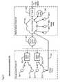
- FIG. 2depicts a schematic diagram of the salient components of network 200 , in accordance with the illustrative embodiment of the present invention.
- FIG. 3depicts a block diagram of the salient components of test station 208 in accordance with the illustrative embodiment of the present invention.
- FIG. 4depicts a block diagram of the salient components of test server 209 in accordance with the illustrative embodiment of the present invention.
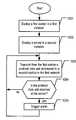
- FIG. 5depicts a flowchart of the salient tasks of a first method for detecting the presence of a hidden wireless router, in accordance with the illustrative embodiment of the present invention.
- FIG. 6depicts a flowchart of the salient tasks of a second method for detecting the presence of a hidden wireless router, in accordance with the illustrative embodiment of the present invention.
- FIG. 7depicts a flowchart of the salient tasks of a third method for detecting the presence of a hidden wireless router, in accordance with the illustrative embodiment of the present invention.
- FIG. 8depicts a flowchart of the salient tasks of a fourth method for detecting the presence of a hidden wireless router, in accordance with the illustrative embodiment of the present invention.
- FIG. 9depicts a flowchart of the salient tasks of a fifth method for detecting the presence of a hidden wireless router, in accordance with the illustrative embodiment of the present invention.
- FIG. 10depicts a flowchart of a method for determining if unauthorized routing between a first network and a second network is occurring, in accordance with the illustrative embodiment of the present invention.
- FIG. 2depicts a schematic diagram of the salient components of telecommunications network 200 , interconnected as shown and in accordance with the illustrative embodiment of the present invention.
- Telecommunications network 200comprises wireless network portion 210 and wireline network portion 220 .
- Wireless clients 201 - 1 through 201 - 3 , access points 202 - 1 and 202 - 2 , and test station 208constitute wireless network portion 210 .
- corporate intranet 204 , firewall 205 , wireline clients 206 - 1 through 206 - 3 , and test server 209constitute wireline network portion 220 .
- Wireless client 201 - iwherein i is all integers selected from the set ⁇ 1, 2, 3 ⁇ , is a device that is used to communicate with other devices, both within network 200 and external to network 200 .
- An example of a wireline clientis a computer that comprises an IEEE 802.11 network interface card. It will be clear to those skilled in the art how to make and use wireless client 201 - i.
- Access point 202 - jprovides for wireless client 201 - i a communications path to devices in networks external to wireless network portion 210 . Furthermore, wireless client 201 - i communicates with other wireless clients in wireless network portion 210 through access point 202 - j , because access point 202 - j coordinates the communications within wireless network portion 210 . It will be clear to those skilled in the art how to make and use access point 202 - j.
- Wireline client 206 - kis a device that is used to communicate with other devices, both within network 200 and external to network 200 .
- An example of a wireline clientis a computer that comprises an Ethernet network interface card. It will be clear to those skilled in the art how to make and use wireline client 206 - k.
- network 200can comprise different numbers of wireless clients, access points, and wireline clients than those depicted.
- Secure access server 203allows access from wireless network portion 210 to wireline network portion 220 .
- Secure access server 203securely interconnects the wireless network with the corporate intranet in well-known fashion.
- Examples of secure access server 203are a main virtual private network (VPN) server, a backup virtual private network server, etc.
- VPNvirtual private network
- Wireless clients 201 - 1 through 201 - 3are required to pass an authentication procedure, supervised by secure access server 203 , to access corporate intranet 204 .
- Wireless clients 201 - 1 through 201 - 3are required to authenticate themselves through secure access server 203 .
- wireless client 201 - 1Although access point 202 - 1 , for example, can be physically located within a physically secure corporate building, wireless client 201 - 1 might be located outside that building, in a car parked across the street from the building and operated by a person who is unauthorized to access the network. Therefore, for pedagogical purposes, wireless client 201 - 1 is a “rogue station” that is attempting to gain illegitimate access to corporate intranet 204 . “Rogue” wireless client 201 - 1 attempts to gain illegitimate access through one of wireless clients 201 - 2 and 201 - 3 , the other wireless clients present. In the pedagogical example, rogue wireless client 201 - 1 attempts to gain access through wireless client 201 - 3 .
- Wireless client 201 - 3is a “hidden wireless router” because it has both a wireless network interface and a wireline network interface via wireless network connection 207 to corporate intranet 204 .
- Such “dual-homed” clientsare not uncommon.
- many laptop computersare equipped with interface cards for both IEEE 802.11 wireless networks and wireline Ethernet-type LANs.
- many corporate networksprovide both wireless access through a system such as IEEE 802.11 and wireline access through network wall jacks located throughout corporate buildings.
- a dual-homed clientsuch as wireless client 201 - 3 must implement routing or bridging, as is known in the art. Routing or bridging causes protocol data units (PDU) that arrive on the wireless interface to leave on the wireline network interface, and vice versa. This can be accomplished with (i) “connection sharing” or (ii) “network address translation,” which are operating system features that are well-known in the art. It will be clear to those skilled in the art how “connection sharing” and “network address translation” can be used to set up protocol data unit forwarding between the wireless and wireline network interfaces of wireless client 201 - 3 . It will also be clear to those skilled in the art how a dual-homed client can be configured to function as a hidden wireless router, either intentionally or unintentionally.
- wireless client 201 - 1can be made aware of the existence of a hidden wireless router, such as wireless client 201 - 3 .
- rogue wireless client 201 - 1can proceed in the following manner to gain illegitimate access to corporate intranet 204 .
- Rogue wireless client 201 - 1sends a protocol data unit through wireless network portion 210 to router wireless client 201 - 3 .
- the path traversed by this protocol data unitcan comprise a network that interconnects two access points, if rogue wireless client 201 - 1 and router wireless client 201 - 3 are associated with two different access points.
- the protocol data unitcomprises (i) a destination address that is outside of wireless network portion 210 (e.g., the address of a server in corporate intranet 204 , etc.), and (ii) a “next-hop” address that is associated with the wireless interface of router wireless client 201 - 3 .
- Next-hop addressesare commonly used to cause a protocol data unit to be routed to a device (such as a router) that is capable of forwarding the protocol data unit to the destination address.
- the “router”is router wireless client 201 - 3 , which forwards the protocol data unit on its wireline interface toward corporate intranet 204 .
- router wireless client 201 - 3forwards by first using the network address translation feature to substitute for the private, non-routable source address of rogue wireless client 201 - 1 the combination of a routable Internet protocol (IP) address of its own wireline interface and an unused Transmission Control Protocol (TCP) or Unnumbered Datagram Protocol (UDP) port number.
- IPInternet protocol
- TCPTransmission Control Protocol
- UDPUnnumbered Datagram Protocol
- the protocol data units that convey the responseare routed to router wireless client 201 - 3 , which then uses its network address translation capability to translate the destination address and port number to the private network layer address (e.g., Internet protocol, etc.) of rogue wireless client 201 - 1 .
- Router wireless client 201 - 3then forwards the protocol data units to rogue wireless client 201 - 1 .
- Test station 208 and test server 209can be used to detect the presence and operation of rogue wireless client 201 - 1 and router wireless client 201 - 3 , in accordance with the illustrative embodiment of the present invention. Test station 208 and test server 209 are described in detail below.
- FIG. 3depicts a block diagram of the salient components of test station 208 in accordance with the illustrative embodiment of the present invention.
- Test station 208comprises receiver 301 , processor 302 , memory 303 , and transmitter 304 , interconnected as shown.
- Test station 208is a device that receives, demodulates, and processes the radio signals emitted by stations on wireless network portion 210 and, in some embodiments, comprises the functionality that is used to determine the presence of rogue wireless client 201 - 1 or router wireless client 201 - 3 or both. In other embodiments, the functionality of the illustrative embodiment resides in access point 202 - j . Furthermore, in some embodiments, test station 208 constitutes a wireless client that can be used to access corporate intranet 204 .
- the addresses detected by test station 208comprise data link layer (DLL) addresses (e.g., Medium Access Control [MAC] layer addresses, etc.) and network layer (NL) addresses (e.g., Internet Protocol [IP] addresses, etc.).
- DLLdata link layer
- NLnetwork layer
- IPInternet Protocol
- Receiver 301is a circuit that is capable of receiving packets from the wireless medium, in well-known fashion, and of forwarding them to processor 302 . It will be clear to those skilled in the art how to make and use receiver 301 .
- Processor 302is a general-purpose processor that is capable of performing the tasks described below and with respect to FIGS. 5 through 10 . It will be clear to those skilled in the art, after reading this specification, how to make and use processor 302 .
- Memory 303is capable of storing programs and data used by processor 302 . It will be clear to those skilled in the art how to make and use memory 303 .
- Transmitter 304is a circuit that is capable of transmitting packets into the wireless medium, in well-known fashion, from processor 304 . It will be clear to those skilled in the art how to make and use transmitter 304 .
- FIG. 4depicts a block diagram of the salient components of test server 209 in accordance with the illustrative embodiment of the present invention.
- Test server 209comprises network interface 401 , processor 402 , and memory 403 , interconnected as shown.
- test server 209is a dedicated device that is added to network 200 .
- the functionality in this specification that is associated with test server 209is resident in a pre-existing device, such as a file server.
- Network interface 401is a circuit that is capable of receiving, in well-known fashion, packets from corporate intranet 204 .
- Network interface 401is also capable of forwarding the packets received to processor 402 . It will be clear to those skilled in the art how to make and use network interface 401 .
- Processor 402is a general-purpose processor that is capable of performing the tasks described below and with respect to FIGS. 5 through 10 . It will be clear to those skilled in the art, after reading this specification, how to make and use processor 402 .
- Memory 403is capable of storing programs and data used by processor 402 . It will be clear to those skilled in the art how to make and use memory 403 .
- FIG. 5depicts a flowchart of the salient tasks of a first method for detecting the presence of a hidden wireless router, represented in the example by wireless client 201 - 3 , in accordance with the illustrative embodiment of the present invention. It will be clear to those skilled in the art which tasks depicted in FIG. 5 can be performed simultaneously or in a different order than that depicted.
- test station 208receives a protocol data unit that comprises a destination address, in accordance with the illustrative embodiment of the present invention.
- the protocol data unitcould have been transmitted by rogue wireless client 201 - 1 .
- the destination addressis a data link layer (e.g., medium access control [MAC] address, etc.).
- the destination addressis a network layer (e.g., Internet protocol, etc.) address.
- a device in network 200compares the destination address of the protocol data unit with the address of secure access server 203 . If the destination address is associated with secure access server 203 , control proceeds to task 501 . If, however, the destination address is not associated with secure access server 203 , control proceeds to task 503 .
- An addresscan be associated with secure access server 203 , for example, by being the address of secure access server 203 itself, or, as another example, by being the address of another device through which protocol data units must pass en route to secure access server 203 .
- the destination addressis possibly associated with wireless client 201 - 3 , the hidden wireless router in the illustrative example.
- the destination addressis associated with a device that is associated with both (i) a network layer address in a first network (e.g., wireless network portion 210 , etc.) and (ii) a network layer address in a second network (e.g., wireline network portion 220 , etc.).
- a network layer address in a first networke.g., wireless network portion 210 , etc.
- a second networke.g., wireline network portion 220 , etc.
- An example of such a deviceis a hidden wireless router.
- a device in network 200triggers an alarm because the destination address is different than the address of secure access server 203 .
- the alarmcomprises the network layer address in a first network or the network layer address in a second network or both.
- FIG. 6depicts a flowchart of the salient tasks of a second method for detecting the presence of a hidden wireless router, in accordance with the illustrative embodiment of the present invention. It will be clear to those skilled in the art which tasks depicted in FIG. 6 can be performed simultaneously or in a different order than that depicted.
- test station 208receives a protocol data unit that comprises a data link layer destination address and a network layer destination address, in accordance with the illustrative embodiment of the present invention.
- the protocol data unitcould have been transmitted by rogue wireless client 201 - 1 .
- a device in network 200examines the data link layer destination address and the network layer destination address of the protocol data unit. If these addresses are associated with secure access server 203 , control proceeds to task 601 . If, however, these addresses are not associated with secure access server 203 , control proceeds to task 603 .
- the destination addressis possibly associated with wireless client 201 - 3 , which is the hidden wireless router in the illustrative example.
- the destination addressis associated with a device that is associated with both (i) a network layer address in a first network (e.g., wireless network portion 210 , etc.) and (ii) a network layer address in a second network (e.g., wireline network portion 220 , etc.).
- a network layer address in a first networke.g., wireless network portion 210 , etc.
- a second networke.g., wireline network portion 220 , etc.
- An example of such a deviceis a hidden wireless router.
- a device in network 200triggers an alarm.
- the alarmcomprises the network layer address in a first network or the network layer address in a second network or both.
- FIG. 7depicts a flowchart of the salient tasks of a third method for detecting the presence of a hidden wireless router, in accordance with the illustrative embodiment of the present invention. It will be clear to those skilled in the art which tasks depicted in FIG. 7 can be performed simultaneously or in a different order than that depicted.
- test station 208 in a first networkreceives a protocol data unit that comprises a network layer destination address in accordance with the illustrative embodiment of the present invention.
- the protocol data unitcould have been transmitted by rogue wireless client 201 - 1 .
- a device in network 200examines the network layer destination address of the protocol data unit. If the address is not associated with a second network (e.g., wireline network portion 220 , etc.), control proceeds to task 701 . If, however, these addresses are associated with the second network, control proceeds to task 703 .
- a second networke.g., wireline network portion 220 , etc.
- the protocol data unitfurther comprises a data link layer destination address that is associated with a device that is, in turn, associated with both (i) a network layer address in a first network (e.g., wireless network portion 210 , etc.) and (ii) a network layer address in a second network (e.g., wireline network portion 220 , etc.).
- a network layer address in a first networke.g., wireless network portion 210 , etc.
- a network layer address in a second networke.g., wireline network portion 220 , etc.
- An example of such a deviceis a hidden wireless router.
- a device in network 200triggers an alarm.
- the alarmcomprises the network layer address in a first network or the network layer address in a second network or both.
- FIG. 8depicts a flowchart of the salient tasks of a fourth method for detecting the presence of a hidden wireless router, in accordance with the illustrative embodiment of the present invention. It will be clear to those skilled in the art which tasks depicted in FIG. 8 can be performed simultaneously or in a different order than that depicted.
- test station 208receives a first protocol data unit, in accordance with the illustrative embodiment of the present invention.
- the first protocol data unitcomprises a data link layer destination address and a first network layer destination address.
- the data link layer destination addressin some embodiments, is associated with a device that is, in turn, associated with both (i) a network layer address in a first network (e.g., wireless network portion 210 , etc.) and (ii) a network layer address in a second network (e.g., wireline network portion 220 , etc.).
- a devicethat is, in turn, associated with both (i) a network layer address in a first network (e.g., wireless network portion 210 , etc.) and (ii) a network layer address in a second network (e.g., wireline network portion 220 , etc.).
- a hidden wireless routere.g., a hidden wireless router.
- test station 208receives a second protocol data unit, in accordance with the illustrative embodiment of the present invention.
- the second protocol data unitcomprises the data link layer destination address and a second network layer destination address.
- a device in network 200compares the data link layer destination address to the data link layer addresses of authorized routers.
- An authorized routeris a router known to the network administrator and one that may legitimately engage in the routing of protocol data units. If the data link layer destination address of the first and second protocol data units is the same as the data link layer address of an authorized router, control proceeds to task 801 . If the data link layer destination address of the first and second protocol data units is different from the data link layer addresses of all authorized routers, control proceeds to task 804 .
- a device in network 200compares the network layer destination address of the first and second protocol data units with each other. If they are the same, control proceeds to task 801 . If they are different, as can be the case for a hidden wireless router, control proceeds to task 805 .
- a device in network 200triggers an alarm.
- the alarmcomprises the network layer address in a first network or the network layer address in a second network or both.
- FIG. 9depicts a flowchart of the salient tasks of a fifth method for detecting the presence of a hidden wireless router, in accordance with the illustrative embodiment of the present invention. It will be clear to those skilled in the art which tasks depicted in FIG. 9 can be performed simultaneously or in a different order than that depicted.
- test station 208receives a protocol data unit that comprises a data link layer destination address and a network layer destination address, in accordance with the illustrative embodiment of the present invention.
- the data link layer destination addressis associated with a device that is, in turn, associated with both (i) a network layer address in a first network (e.g., wireless network portion 210 , etc.) and (ii) a network layer address in a second network (e.g., wireline network portion 220 , etc.).
- a first networke.g., wireless network portion 210 , etc.
- a network layer address in a second networke.g., wireline network portion 220 , etc.
- An example of such a deviceis a hidden wireless router.
- a device in network 200determines whether or not the data link layer destination address of the protocol data unit received at task 901 is associated with the same device as the network layer destination address of the protocol data unit. If the data link layer destination address and the network layer destination address are associated with the same device, then control proceeds to task 901 . If the data link layer destination address and the network layer destination address are associated with different devices, then control proceeds to task 903 .
- a device in network 200triggers an alarm.
- the alarmcomprises the network layer address in a first network or the network layer address in a second network or both.
- FIG. 10depicts a flowchart of a method for determining if unauthorized routing between a first network (e.g., wireless network portion 210 , etc.) and a second network (e.g., wireline network portion 220 , etc.) is occurring, in accordance with the illustrative embodiment of the present invention. It will be clear to those skilled in the art which tasks depicted in FIG. 10 can be performed simultaneously or in a different order than that depicted.
- a first networke.g., wireless network portion 210 , etc.
- a second networke.g., wireline network portion 220 , etc.
- a first station, test station 208is deployed in a first network, an example being wireless network portion 210 .
- a server, test server 209is deployed in a second network, an example being wireline network portion 220 .
- the first networkis connected to the second network through a secure access server, such as secure access server 203 .
- test station 208attempts to send a protocol data unit to test server 209 in the second network via a second station, wireless client 201 - 3 , in the first network.
- test station 208sends the protocol data unit to test server 209 by transmitting to wireless client 201 - 3 a protocol data unit having a destination address equal to an address of test server 209 .
- the protocol data unitcomprises a network layer address source address of the second station.
- controlproceeds to task 1005 . If the protocol data unit was not received at test server 209 , control proceeds to task 1003 .
- test server 209(or some other device in network 200 ) triggers an alarm.
- the alarmcomprises a network layer address in the first network (e.g., the source address of the second station, etc.) or a network layer address in the second network or both.
- test server 209can be arranged to record the network layer source address of the protocol data unit, and then use that network layer source address as a means of identifying the logical network location and physical location of the hidden wireless router so that it can be disabled.
- the network layer source address as recorded at test server 209can be used as an index into a database relating network layer addresses of wireline network stations to corresponding wireline network port numbers, thereby obtaining the wireline network port number of the hidden wireless router. Steps can then be taken to disable the network jack associated with that port number, or, alternatively, administrative personnel can physically unplug or otherwise disable the hidden wireless router.
Landscapes
- Engineering & Computer Science (AREA)
- Computer Security & Cryptography (AREA)
- Computer Networks & Wireless Communication (AREA)
- Signal Processing (AREA)
- Computer Hardware Design (AREA)
- Computing Systems (AREA)
- General Engineering & Computer Science (AREA)
- Mobile Radio Communication Systems (AREA)
Abstract
Description
Claims (3)
Priority Applications (1)
| Application Number | Priority Date | Filing Date | Title |
|---|---|---|---|
| US10/757,676US7840698B2 (en) | 2003-09-12 | 2004-01-14 | Detection of hidden wireless routers |
Applications Claiming Priority (2)
| Application Number | Priority Date | Filing Date | Title |
|---|---|---|---|
| US50248603P | 2003-09-12 | 2003-09-12 | |
| US10/757,676US7840698B2 (en) | 2003-09-12 | 2004-01-14 | Detection of hidden wireless routers |
Publications (2)
| Publication Number | Publication Date |
|---|---|
| US20050060434A1 US20050060434A1 (en) | 2005-03-17 |
| US7840698B2true US7840698B2 (en) | 2010-11-23 |
Family
ID=34278830
Family Applications (1)
| Application Number | Title | Priority Date | Filing Date |
|---|---|---|---|
| US10/757,676Active2028-06-25US7840698B2 (en) | 2003-09-12 | 2004-01-14 | Detection of hidden wireless routers |
Country Status (1)
| Country | Link |
|---|---|
| US (1) | US7840698B2 (en) |
Families Citing this family (12)
| Publication number | Priority date | Publication date | Assignee | Title |
|---|---|---|---|---|
| US6732105B1 (en)* | 2001-07-27 | 2004-05-04 | Palmone, Inc. | Secure authentication proxy architecture for a web-based wireless intranet application |
| US8174378B2 (en)* | 2005-03-18 | 2012-05-08 | Richman Technology Corporation | Human guard enhancing multiple site security system |
| US20070008974A1 (en)* | 2005-07-07 | 2007-01-11 | International Business Machines Corporation | Method, apparatus and computer program product for network services |
| CN101651537B (en)* | 2008-08-15 | 2013-07-10 | 上海贝尔阿尔卡特股份有限公司 | Method and device for performing distributed security control in communication network system |
| US8391283B2 (en)* | 2009-07-09 | 2013-03-05 | Yehuda Zisapel | System and method for obtaining physical location information for networked devices |
| WO2012050546A1 (en)* | 2010-10-15 | 2012-04-19 | Thomson Licensing | System and method for configuration access via connected devices |
| US20140045596A1 (en)* | 2012-08-07 | 2014-02-13 | Lawrence Cameron Vaughan | Methods and systems for determining the location of online gaming clients |
| IL229153B (en) | 2013-10-30 | 2019-02-28 | Verint Systems Ltd | Systems and methods for protocol-based identification of rogue base stations |
| US9525689B2 (en) | 2014-03-25 | 2016-12-20 | Symbol Technologies, Llc | Detection of an unauthorized wireless communication device |
| US10055581B2 (en)* | 2014-06-24 | 2018-08-21 | Symbol Technologies, Llc | Locating a wireless communication attack |
| US10684030B2 (en)* | 2015-03-05 | 2020-06-16 | Honeywell International Inc. | Wireless actuator service |
| IL287365A (en)* | 2021-10-18 | 2023-05-01 | Cognyte Tech Israel Ltd | System and method for estimating properties associated with routers |
Citations (9)
| Publication number | Priority date | Publication date | Assignee | Title |
|---|---|---|---|---|
| US5922073A (en) | 1996-01-10 | 1999-07-13 | Canon Kabushiki Kaisha | System and method for controlling access to subject data using location data associated with the subject data and a requesting device |
| US5943425A (en) | 1996-05-10 | 1999-08-24 | Lucent Technologies, Inc. | Re-authentication procedure for over-the-air activation |
| US6377810B1 (en) | 1999-06-11 | 2002-04-23 | Motorola, Inc. | Method of operation of mobile wireless communication system with location information |
| US20020073338A1 (en)* | 2000-11-22 | 2002-06-13 | Compaq Information Technologies Group, L.P. | Method and system for limiting the impact of undesirable behavior of computers on a shared data network |
| US20020078202A1 (en)* | 2000-12-15 | 2002-06-20 | Tadanao Ando | IP network system having unauthorized intrusion safeguard function |
| US20020161920A1 (en)* | 2001-04-19 | 2002-10-31 | International Business Machines Corporation | Router search system, router search method and router search program |
| US6522888B1 (en) | 1999-08-31 | 2003-02-18 | Lucent Technologies Inc. | System for determining wireless coverage using location information for a wireless unit |
| US20030087629A1 (en)* | 2001-09-28 | 2003-05-08 | Bluesocket, Inc. | Method and system for managing data traffic in wireless networks |
| US6577274B1 (en) | 2001-12-19 | 2003-06-10 | Intel Corporation | Method and apparatus for controlling access to mobile devices |
- 2004
- 2004-01-14USUS10/757,676patent/US7840698B2/enactiveActive
Patent Citations (9)
| Publication number | Priority date | Publication date | Assignee | Title |
|---|---|---|---|---|
| US5922073A (en) | 1996-01-10 | 1999-07-13 | Canon Kabushiki Kaisha | System and method for controlling access to subject data using location data associated with the subject data and a requesting device |
| US5943425A (en) | 1996-05-10 | 1999-08-24 | Lucent Technologies, Inc. | Re-authentication procedure for over-the-air activation |
| US6377810B1 (en) | 1999-06-11 | 2002-04-23 | Motorola, Inc. | Method of operation of mobile wireless communication system with location information |
| US6522888B1 (en) | 1999-08-31 | 2003-02-18 | Lucent Technologies Inc. | System for determining wireless coverage using location information for a wireless unit |
| US20020073338A1 (en)* | 2000-11-22 | 2002-06-13 | Compaq Information Technologies Group, L.P. | Method and system for limiting the impact of undesirable behavior of computers on a shared data network |
| US20020078202A1 (en)* | 2000-12-15 | 2002-06-20 | Tadanao Ando | IP network system having unauthorized intrusion safeguard function |
| US20020161920A1 (en)* | 2001-04-19 | 2002-10-31 | International Business Machines Corporation | Router search system, router search method and router search program |
| US20030087629A1 (en)* | 2001-09-28 | 2003-05-08 | Bluesocket, Inc. | Method and system for managing data traffic in wireless networks |
| US6577274B1 (en) | 2001-12-19 | 2003-06-10 | Intel Corporation | Method and apparatus for controlling access to mobile devices |
Non-Patent Citations (1)
| Title |
|---|
| Sara Harris, VPN and WEP, Wireless 802.11b security in a corporate environment, Intel Information Technology White Paper, Jan. 2003. |
Also Published As
| Publication number | Publication date |
|---|---|
| US20050060434A1 (en) | 2005-03-17 |
Similar Documents
| Publication | Publication Date | Title |
|---|---|---|
| US7970894B1 (en) | Method and system for monitoring of wireless devices in local area computer networks | |
| US7100201B2 (en) | Undetectable firewall | |
| US8082578B2 (en) | Intelligent firewall | |
| US7440434B2 (en) | Method and system for detecting wireless access devices operably coupled to computer local area networks and related methods | |
| JP4174392B2 (en) | Network unauthorized connection prevention system and network unauthorized connection prevention device | |
| US8200798B2 (en) | Address security in a routed access network | |
| US7971253B1 (en) | Method and system for detecting address rotation and related events in communication networks | |
| US8107396B1 (en) | Host tracking in a layer 2 IP ethernet network | |
| US7765309B2 (en) | Wireless provisioning device | |
| US20080270606A1 (en) | Remote client remediation | |
| US7570625B1 (en) | Detection of wireless devices | |
| CA2600755A1 (en) | Real-time mobile user network operations center | |
| US7840698B2 (en) | Detection of hidden wireless routers | |
| WO2005015871A1 (en) | Method, program and system for automatically detecting malicius computer network reconnaissance | |
| Mahmood et al. | Network security issues of data link layer: An overview | |
| CN113242270A (en) | Data transmission method, device and system based on virtualization network | |
| TWI474668B (en) | Method for distinguishing and blocking off network node | |
| Rahman et al. | Holistic approach to arp poisoning and countermeasures by using practical examples and paradigm | |
| US20090213752A1 (en) | Detecting Double Attachment Between a Wired Network and At Least One Wireless Network | |
| KR101871146B1 (en) | Network switch apparatus for blocking an unauthorized terminal and Blocking method for the unauthorized terminal | |
| Achari | Advanced Cybersecurity Tactics | |
| FI120226B (en) | Procedure for identifying a terminal equipment | |
| KR100564750B1 (en) | Connection-based Backtracking Device Using TPC Connection Interception and Its Method | |
| KR20050029800A (en) | Network connection control method | |
| WO2009011659A1 (en) | Protocol remapping method and method of detecting possible attacks on a network |
Legal Events
| Date | Code | Title | Description |
|---|---|---|---|
| AS | Assignment | Owner name:AVAYA TECHNOLOGY CORP., NEW JERSEY Free format text:ASSIGNMENT OF ASSIGNORS INTEREST;ASSIGNORS:FAZAL, LOOKMAN;KAPPES, MARTIN;KRISHNAKUMAR, ANJUR SUNDARESAN;AND OTHERS;REEL/FRAME:014914/0863 Effective date:20040109 | |
| AS | Assignment | Owner name:CITIBANK, N.A., AS ADMINISTRATIVE AGENT, NEW YORK Free format text:SECURITY AGREEMENT;ASSIGNORS:AVAYA, INC.;AVAYA TECHNOLOGY LLC;OCTEL COMMUNICATIONS LLC;AND OTHERS;REEL/FRAME:020156/0149 Effective date:20071026 Owner name:CITIBANK, N.A., AS ADMINISTRATIVE AGENT,NEW YORK Free format text:SECURITY AGREEMENT;ASSIGNORS:AVAYA, INC.;AVAYA TECHNOLOGY LLC;OCTEL COMMUNICATIONS LLC;AND OTHERS;REEL/FRAME:020156/0149 Effective date:20071026 | |
| AS | Assignment | Owner name:CITICORP USA, INC., AS ADMINISTRATIVE AGENT, NEW Y Free format text:SECURITY AGREEMENT;ASSIGNORS:AVAYA, INC.;AVAYA TECHNOLOGY LLC;OCTEL COMMUNICATIONS LLC;AND OTHERS;REEL/FRAME:020166/0705 Effective date:20071026 Owner name:CITICORP USA, INC., AS ADMINISTRATIVE AGENT, NEW YORK Free format text:SECURITY AGREEMENT;ASSIGNORS:AVAYA, INC.;AVAYA TECHNOLOGY LLC;OCTEL COMMUNICATIONS LLC;AND OTHERS;REEL/FRAME:020166/0705 Effective date:20071026 Owner name:CITICORP USA, INC., AS ADMINISTRATIVE AGENT,NEW YO Free format text:SECURITY AGREEMENT;ASSIGNORS:AVAYA, INC.;AVAYA TECHNOLOGY LLC;OCTEL COMMUNICATIONS LLC;AND OTHERS;REEL/FRAME:020166/0705 Effective date:20071026 | |
| AS | Assignment | Owner name:AVAYA INC, NEW JERSEY Free format text:REASSIGNMENT;ASSIGNORS:AVAYA TECHNOLOGY LLC;AVAYA LICENSING LLC;REEL/FRAME:021156/0082 Effective date:20080626 Owner name:AVAYA INC,NEW JERSEY Free format text:REASSIGNMENT;ASSIGNORS:AVAYA TECHNOLOGY LLC;AVAYA LICENSING LLC;REEL/FRAME:021156/0082 Effective date:20080626 | |
| AS | Assignment | Owner name:AVAYA TECHNOLOGY LLC, NEW JERSEY Free format text:CONVERSION FROM CORP TO LLC;ASSIGNOR:AVAYA TECHNOLOGY CORP.;REEL/FRAME:022677/0550 Effective date:20050930 Owner name:AVAYA TECHNOLOGY LLC,NEW JERSEY Free format text:CONVERSION FROM CORP TO LLC;ASSIGNOR:AVAYA TECHNOLOGY CORP.;REEL/FRAME:022677/0550 Effective date:20050930 | |
| STCF | Information on status: patent grant | Free format text:PATENTED CASE | |
| AS | Assignment | Owner name:BANK OF NEW YORK MELLON TRUST, NA, AS NOTES COLLATERAL AGENT, THE, PENNSYLVANIA Free format text:SECURITY AGREEMENT;ASSIGNOR:AVAYA INC., A DELAWARE CORPORATION;REEL/FRAME:025863/0535 Effective date:20110211 Owner name:BANK OF NEW YORK MELLON TRUST, NA, AS NOTES COLLAT Free format text:SECURITY AGREEMENT;ASSIGNOR:AVAYA INC., A DELAWARE CORPORATION;REEL/FRAME:025863/0535 Effective date:20110211 | |
| AS | Assignment | Owner name:BANK OF NEW YORK MELLON TRUST COMPANY, N.A., THE, PENNSYLVANIA Free format text:SECURITY AGREEMENT;ASSIGNOR:AVAYA, INC.;REEL/FRAME:030083/0639 Effective date:20130307 Owner name:BANK OF NEW YORK MELLON TRUST COMPANY, N.A., THE, Free format text:SECURITY AGREEMENT;ASSIGNOR:AVAYA, INC.;REEL/FRAME:030083/0639 Effective date:20130307 | |
| FPAY | Fee payment | Year of fee payment:4 | |
| AS | Assignment | Owner name:CITIBANK, N.A., AS ADMINISTRATIVE AGENT, NEW YORK Free format text:SECURITY INTEREST;ASSIGNORS:AVAYA INC.;AVAYA INTEGRATED CABINET SOLUTIONS INC.;OCTEL COMMUNICATIONS CORPORATION;AND OTHERS;REEL/FRAME:041576/0001 Effective date:20170124 | |
| AS | Assignment | Owner name:OCTEL COMMUNICATIONS LLC (FORMERLY KNOWN AS OCTEL COMMUNICATIONS CORPORATION), CALIFORNIA Free format text:BANKRUPTCY COURT ORDER RELEASING ALL LIENS INCLUDING THE SECURITY INTEREST RECORDED AT REEL/FRAME 041576/0001;ASSIGNOR:CITIBANK, N.A.;REEL/FRAME:044893/0531 Effective date:20171128 Owner name:AVAYA INTEGRATED CABINET SOLUTIONS INC., CALIFORNIA Free format text:BANKRUPTCY COURT ORDER RELEASING ALL LIENS INCLUDING THE SECURITY INTEREST RECORDED AT REEL/FRAME 041576/0001;ASSIGNOR:CITIBANK, N.A.;REEL/FRAME:044893/0531 Effective date:20171128 Owner name:AVAYA INC., CALIFORNIA Free format text:BANKRUPTCY COURT ORDER RELEASING ALL LIENS INCLUDING THE SECURITY INTEREST RECORDED AT REEL/FRAME 025863/0535;ASSIGNOR:THE BANK OF NEW YORK MELLON TRUST, NA;REEL/FRAME:044892/0001 Effective date:20171128 Owner name:AVAYA INTEGRATED CABINET SOLUTIONS INC., CALIFORNI Free format text:BANKRUPTCY COURT ORDER RELEASING ALL LIENS INCLUDING THE SECURITY INTEREST RECORDED AT REEL/FRAME 041576/0001;ASSIGNOR:CITIBANK, N.A.;REEL/FRAME:044893/0531 Effective date:20171128 Owner name:VPNET TECHNOLOGIES, INC., CALIFORNIA Free format text:BANKRUPTCY COURT ORDER RELEASING ALL LIENS INCLUDING THE SECURITY INTEREST RECORDED AT REEL/FRAME 041576/0001;ASSIGNOR:CITIBANK, N.A.;REEL/FRAME:044893/0531 Effective date:20171128 Owner name:OCTEL COMMUNICATIONS LLC (FORMERLY KNOWN AS OCTEL Free format text:BANKRUPTCY COURT ORDER RELEASING ALL LIENS INCLUDING THE SECURITY INTEREST RECORDED AT REEL/FRAME 041576/0001;ASSIGNOR:CITIBANK, N.A.;REEL/FRAME:044893/0531 Effective date:20171128 Owner name:AVAYA INC., CALIFORNIA Free format text:BANKRUPTCY COURT ORDER RELEASING ALL LIENS INCLUDING THE SECURITY INTEREST RECORDED AT REEL/FRAME 041576/0001;ASSIGNOR:CITIBANK, N.A.;REEL/FRAME:044893/0531 Effective date:20171128 Owner name:AVAYA INC., CALIFORNIA Free format text:BANKRUPTCY COURT ORDER RELEASING ALL LIENS INCLUDING THE SECURITY INTEREST RECORDED AT REEL/FRAME 030083/0639;ASSIGNOR:THE BANK OF NEW YORK MELLON TRUST COMPANY, N.A.;REEL/FRAME:045012/0666 Effective date:20171128 | |
| AS | Assignment | Owner name:GOLDMAN SACHS BANK USA, AS COLLATERAL AGENT, NEW YORK Free format text:SECURITY INTEREST;ASSIGNORS:AVAYA INC.;AVAYA INTEGRATED CABINET SOLUTIONS LLC;OCTEL COMMUNICATIONS LLC;AND OTHERS;REEL/FRAME:045034/0001 Effective date:20171215 Owner name:GOLDMAN SACHS BANK USA, AS COLLATERAL AGENT, NEW Y Free format text:SECURITY INTEREST;ASSIGNORS:AVAYA INC.;AVAYA INTEGRATED CABINET SOLUTIONS LLC;OCTEL COMMUNICATIONS LLC;AND OTHERS;REEL/FRAME:045034/0001 Effective date:20171215 | |
| AS | Assignment | Owner name:CITIBANK, N.A., AS COLLATERAL AGENT, NEW YORK Free format text:SECURITY INTEREST;ASSIGNORS:AVAYA INC.;AVAYA INTEGRATED CABINET SOLUTIONS LLC;OCTEL COMMUNICATIONS LLC;AND OTHERS;REEL/FRAME:045124/0026 Effective date:20171215 | |
| MAFP | Maintenance fee payment | Free format text:PAYMENT OF MAINTENANCE FEE, 8TH YEAR, LARGE ENTITY (ORIGINAL EVENT CODE: M1552) Year of fee payment:8 | |
| AS | Assignment | Owner name:WILMINGTON TRUST, NATIONAL ASSOCIATION, MINNESOTA Free format text:SECURITY INTEREST;ASSIGNORS:AVAYA INC.;AVAYA MANAGEMENT L.P.;INTELLISIST, INC.;AND OTHERS;REEL/FRAME:053955/0436 Effective date:20200925 | |
| MAFP | Maintenance fee payment | Free format text:PAYMENT OF MAINTENANCE FEE, 12TH YEAR, LARGE ENTITY (ORIGINAL EVENT CODE: M1553); ENTITY STATUS OF PATENT OWNER: LARGE ENTITY Year of fee payment:12 | |
| AS | Assignment | Owner name:WILMINGTON TRUST, NATIONAL ASSOCIATION, AS COLLATERAL AGENT, DELAWARE Free format text:INTELLECTUAL PROPERTY SECURITY AGREEMENT;ASSIGNORS:AVAYA INC.;INTELLISIST, INC.;AVAYA MANAGEMENT L.P.;AND OTHERS;REEL/FRAME:061087/0386 Effective date:20220712 | |
| AS | Assignment | Owner name:AVAYA INTEGRATED CABINET SOLUTIONS LLC, NEW JERSEY Free format text:RELEASE OF SECURITY INTEREST IN PATENTS AT REEL 45124/FRAME 0026;ASSIGNOR:CITIBANK, N.A., AS COLLATERAL AGENT;REEL/FRAME:063457/0001 Effective date:20230403 Owner name:AVAYA MANAGEMENT L.P., NEW JERSEY Free format text:RELEASE OF SECURITY INTEREST IN PATENTS AT REEL 45124/FRAME 0026;ASSIGNOR:CITIBANK, N.A., AS COLLATERAL AGENT;REEL/FRAME:063457/0001 Effective date:20230403 Owner name:AVAYA INC., NEW JERSEY Free format text:RELEASE OF SECURITY INTEREST IN PATENTS AT REEL 45124/FRAME 0026;ASSIGNOR:CITIBANK, N.A., AS COLLATERAL AGENT;REEL/FRAME:063457/0001 Effective date:20230403 Owner name:AVAYA HOLDINGS CORP., NEW JERSEY Free format text:RELEASE OF SECURITY INTEREST IN PATENTS AT REEL 45124/FRAME 0026;ASSIGNOR:CITIBANK, N.A., AS COLLATERAL AGENT;REEL/FRAME:063457/0001 Effective date:20230403 | |
| AS | Assignment | Owner name:WILMINGTON SAVINGS FUND SOCIETY, FSB (COLLATERAL AGENT), DELAWARE Free format text:INTELLECTUAL PROPERTY SECURITY AGREEMENT;ASSIGNORS:AVAYA MANAGEMENT L.P.;AVAYA INC.;INTELLISIST, INC.;AND OTHERS;REEL/FRAME:063742/0001 Effective date:20230501 | |
| AS | Assignment | Owner name:CITIBANK, N.A., AS COLLATERAL AGENT, NEW YORK Free format text:INTELLECTUAL PROPERTY SECURITY AGREEMENT;ASSIGNORS:AVAYA INC.;AVAYA MANAGEMENT L.P.;INTELLISIST, INC.;REEL/FRAME:063542/0662 Effective date:20230501 | |
| AS | Assignment | Owner name:AVAYA MANAGEMENT L.P., NEW JERSEY Free format text:RELEASE OF SECURITY INTEREST IN PATENTS (REEL/FRAME 045034/0001);ASSIGNOR:GOLDMAN SACHS BANK USA., AS COLLATERAL AGENT;REEL/FRAME:063779/0622 Effective date:20230501 Owner name:CAAS TECHNOLOGIES, LLC, NEW JERSEY Free format text:RELEASE OF SECURITY INTEREST IN PATENTS (REEL/FRAME 045034/0001);ASSIGNOR:GOLDMAN SACHS BANK USA., AS COLLATERAL AGENT;REEL/FRAME:063779/0622 Effective date:20230501 Owner name:HYPERQUALITY II, LLC, NEW JERSEY Free format text:RELEASE OF SECURITY INTEREST IN PATENTS (REEL/FRAME 045034/0001);ASSIGNOR:GOLDMAN SACHS BANK USA., AS COLLATERAL AGENT;REEL/FRAME:063779/0622 Effective date:20230501 Owner name:HYPERQUALITY, INC., NEW JERSEY Free format text:RELEASE OF SECURITY INTEREST IN PATENTS (REEL/FRAME 045034/0001);ASSIGNOR:GOLDMAN SACHS BANK USA., AS COLLATERAL AGENT;REEL/FRAME:063779/0622 Effective date:20230501 Owner name:ZANG, INC. (FORMER NAME OF AVAYA CLOUD INC.), NEW JERSEY Free format text:RELEASE OF SECURITY INTEREST IN PATENTS (REEL/FRAME 045034/0001);ASSIGNOR:GOLDMAN SACHS BANK USA., AS COLLATERAL AGENT;REEL/FRAME:063779/0622 Effective date:20230501 Owner name:VPNET TECHNOLOGIES, INC., NEW JERSEY Free format text:RELEASE OF SECURITY INTEREST IN PATENTS (REEL/FRAME 045034/0001);ASSIGNOR:GOLDMAN SACHS BANK USA., AS COLLATERAL AGENT;REEL/FRAME:063779/0622 Effective date:20230501 Owner name:OCTEL COMMUNICATIONS LLC, NEW JERSEY Free format text:RELEASE OF SECURITY INTEREST IN PATENTS (REEL/FRAME 045034/0001);ASSIGNOR:GOLDMAN SACHS BANK USA., AS COLLATERAL AGENT;REEL/FRAME:063779/0622 Effective date:20230501 Owner name:AVAYA INTEGRATED CABINET SOLUTIONS LLC, NEW JERSEY Free format text:RELEASE OF SECURITY INTEREST IN PATENTS (REEL/FRAME 045034/0001);ASSIGNOR:GOLDMAN SACHS BANK USA., AS COLLATERAL AGENT;REEL/FRAME:063779/0622 Effective date:20230501 Owner name:INTELLISIST, INC., NEW JERSEY Free format text:RELEASE OF SECURITY INTEREST IN PATENTS (REEL/FRAME 045034/0001);ASSIGNOR:GOLDMAN SACHS BANK USA., AS COLLATERAL AGENT;REEL/FRAME:063779/0622 Effective date:20230501 Owner name:AVAYA INC., NEW JERSEY Free format text:RELEASE OF SECURITY INTEREST IN PATENTS (REEL/FRAME 045034/0001);ASSIGNOR:GOLDMAN SACHS BANK USA., AS COLLATERAL AGENT;REEL/FRAME:063779/0622 Effective date:20230501 Owner name:AVAYA INTEGRATED CABINET SOLUTIONS LLC, NEW JERSEY Free format text:RELEASE OF SECURITY INTEREST IN PATENTS (REEL/FRAME 53955/0436);ASSIGNOR:WILMINGTON TRUST, NATIONAL ASSOCIATION, AS NOTES COLLATERAL AGENT;REEL/FRAME:063705/0023 Effective date:20230501 Owner name:INTELLISIST, INC., NEW JERSEY Free format text:RELEASE OF SECURITY INTEREST IN PATENTS (REEL/FRAME 53955/0436);ASSIGNOR:WILMINGTON TRUST, NATIONAL ASSOCIATION, AS NOTES COLLATERAL AGENT;REEL/FRAME:063705/0023 Effective date:20230501 Owner name:AVAYA INC., NEW JERSEY Free format text:RELEASE OF SECURITY INTEREST IN PATENTS (REEL/FRAME 53955/0436);ASSIGNOR:WILMINGTON TRUST, NATIONAL ASSOCIATION, AS NOTES COLLATERAL AGENT;REEL/FRAME:063705/0023 Effective date:20230501 Owner name:AVAYA MANAGEMENT L.P., NEW JERSEY Free format text:RELEASE OF SECURITY INTEREST IN PATENTS (REEL/FRAME 53955/0436);ASSIGNOR:WILMINGTON TRUST, NATIONAL ASSOCIATION, AS NOTES COLLATERAL AGENT;REEL/FRAME:063705/0023 Effective date:20230501 Owner name:AVAYA INTEGRATED CABINET SOLUTIONS LLC, NEW JERSEY Free format text:RELEASE OF SECURITY INTEREST IN PATENTS (REEL/FRAME 61087/0386);ASSIGNOR:WILMINGTON TRUST, NATIONAL ASSOCIATION, AS NOTES COLLATERAL AGENT;REEL/FRAME:063690/0359 Effective date:20230501 Owner name:INTELLISIST, INC., NEW JERSEY Free format text:RELEASE OF SECURITY INTEREST IN PATENTS (REEL/FRAME 61087/0386);ASSIGNOR:WILMINGTON TRUST, NATIONAL ASSOCIATION, AS NOTES COLLATERAL AGENT;REEL/FRAME:063690/0359 Effective date:20230501 Owner name:AVAYA INC., NEW JERSEY Free format text:RELEASE OF SECURITY INTEREST IN PATENTS (REEL/FRAME 61087/0386);ASSIGNOR:WILMINGTON TRUST, NATIONAL ASSOCIATION, AS NOTES COLLATERAL AGENT;REEL/FRAME:063690/0359 Effective date:20230501 Owner name:AVAYA MANAGEMENT L.P., NEW JERSEY Free format text:RELEASE OF SECURITY INTEREST IN PATENTS (REEL/FRAME 61087/0386);ASSIGNOR:WILMINGTON TRUST, NATIONAL ASSOCIATION, AS NOTES COLLATERAL AGENT;REEL/FRAME:063690/0359 Effective date:20230501 | |
| AS | Assignment | Owner name:AVAYA LLC, DELAWARE Free format text:(SECURITY INTEREST) GRANTOR'S NAME CHANGE;ASSIGNOR:AVAYA INC.;REEL/FRAME:065019/0231 Effective date:20230501 |