US7839771B2 - Backhaul failover method and system for a wireless network - Google Patents
Backhaul failover method and system for a wireless networkDownload PDFInfo
- Publication number
- US7839771B2 US7839771B2US12/070,863US7086308AUS7839771B2US 7839771 B2US7839771 B2US 7839771B2US 7086308 AUS7086308 AUS 7086308AUS 7839771 B2US7839771 B2US 7839771B2
- Authority
- US
- United States
- Prior art keywords
- access point
- radio
- link
- wired
- client node
- Prior art date
- Legal status (The legal status is an assumption and is not a legal conclusion. Google has not performed a legal analysis and makes no representation as to the accuracy of the status listed.)
- Active, expires
Links
- 238000000034methodMethods0.000titleclaimsabstractdescription47
- 238000004891communicationMethods0.000claimsabstractdescription52
- 238000001514detection methodMethods0.000claimsabstractdescription12
- 238000011084recoveryMethods0.000claimsdescription18
- 230000000737periodic effectEffects0.000claimsdescription6
- 101100513046Neurospora crassa (strain ATCC 24698 / 74-OR23-1A / CBS 708.71 / DSM 1257 / FGSC 987) eth-1 geneProteins0.000description6
- 238000010586diagramMethods0.000description4
- 235000008694Humulus lupulusNutrition0.000description1
- 230000005540biological transmissionEffects0.000description1
- 238000012986modificationMethods0.000description1
- 230000004048modificationEffects0.000description1
Images


Classifications
- H—ELECTRICITY
- H04—ELECTRIC COMMUNICATION TECHNIQUE
- H04W—WIRELESS COMMUNICATION NETWORKS
- H04W24/00—Supervisory, monitoring or testing arrangements
- H04W24/04—Arrangements for maintaining operational condition
- H—ELECTRICITY
- H04—ELECTRIC COMMUNICATION TECHNIQUE
- H04W—WIRELESS COMMUNICATION NETWORKS
- H04W88/00—Devices specially adapted for wireless communication networks, e.g. terminals, base stations or access point devices
- H04W88/08—Access point devices
- H04W88/10—Access point devices adapted for operation in multiple networks, e.g. multi-mode access points
Definitions
- This inventionrelates to wireless networks and more particularly to a method and system for enabling a wireless network to prevent loss of connection to a wired network.
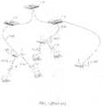
- FIG. 1illustrates a known backhaul network topology 10 for connecting all access points in a wireless access network to a backhaul network.
- access points AP 1 and AP 2each have a wired backhaul connection to an external backhaul network, such as a local area network (LAN) or the Internet.
- LANlocal area network
- Each wired backhaul connectionenables access to and from the external network in a conventional manner, e.g., by means of Ethernet links Eth 0 and Eth 1 to respective access switches 2 , 4 , and finally to a distribution switch 6 .
- other access pointse.g., an access point AP 3
- the access points AP 1 and AP 2typically include at least two wireless radio transceivers for providing wireless interfaces to connect client nodes to the backhaul network via these access points.
- the wireless radio transceiver interfacestypically operate in accordance with the International Electrical and Electronic Engineers (IEEE) 802.11 Standard, such as version IEEE Std. 802.11-1997. According to the Standard, there are various officially published protocols, including 802.11b, 802.11g, and 802.11a.
- a wireless channel operating in accordance with 802.11b or 11goperates in the 2.4 GHz range.
- a channel operating in accordance with 802.11aoperates in the 5 GHz range. In the example in FIG.
- AP 1provides one radio for enabling client node 8 to connect wirelessly to the wired backhaul network in accordance with an 802.11b or 802.11g interface protocol. This wireless connection is identified in FIG. 1 as “11b/g”.
- a second radiois provided for enabling client node 12 to connect wirelessly to the wired backhaul network in accordance with an 802.11a. This wireless connection is identified in FIG. 1 as “11a” interface protocol.
- second access point AP 2enables wireless client nodes 14 and 16 to connect to the wired backhaul network via an Ethernet connection Eth 1 and respective wireless connections 11b/g and 11a.
- FIG. 2illustrates a known access point AP 1 in the system in FIG. 1 .
- the access pointincludes at least two radios, including one radio operating at 2.4 GHz, e.g., for 11b/g, and one radio operating at 5 GHz, e.g., for 11a. Additional 2.4 GHz radios may be provided in AP 1 , shown in phantom in FIG. 2 .
- one or more of the wireless channelsmay be operated in accordance with other suitable protocols including, for example, the 802.11n protocol (also commonly called the 11n protocol.). 801.11n is currently just a proposed protocol, the specification of which has not yet been finalized and officially published by IEEE.
- 802.11nalso commonly called the 11n protocol.
- 801.11nis currently just a proposed protocol, the specification of which has not yet been finalized and officially published by IEEE.
- a drawback of the known topologyis that, if one of the wired Ethernet links fails, such as due to uplink network problems, the access point associated with that wired link will lose connection to the backhaul network. Consequently, that access point will be unable to continue to provide wireless network access to its associated client nodes. That is, no “failover” capability is provided to recover from the loss of the wired connection in topology.
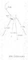
- FIG. 3illustrates a known wireless mesh network topology in which an access point has one radio statically configured in an access mode and another radio statically configured in a backhaul mode.
- an access point AP 3has one radio statically configured in an access mode for enabling a communications path with a corresponding client node 22 .
- Access point AP 3 according to topologyhas no direct wired connection to the backhaul network.
- Access point AP 3has another wireless radio that is statically configured in a backhaul mode.
- access point AP 3connects wirelessly to another access point AP 4 which has a wired Ethernet link, Eth, to a backhaul switch 4 .
- Ethwired Ethernet link
- a drawback of the wireless mesh network topologyis that it does not provide failover to protect the wired backhaul connection. That is, if the wired Ethernet link Eth fails, access points AP 3 and AP 4 , and in turn client node 22 , will lose connection to the backhaul switch 4 .
- Another drawback of topologyis that one of the two radios in AP 3 must be dedicated to the backhaul mode. Consequently, that dedicated radio cannot operate in an access mode to provide access service to client nodes. As a result, topology reduces the number of client nodes which can be served by the access point AP 3 and reduces the total access bandwidth provided by this single access point.
- What is neededis an access point that provides failover capability to enable recovery from a failure of the wired backhaul connection, while providing efficient access in normal operation in order to maximize the access services to its wireless clients. Therefore, what is needed is a method and system in an access point that enables one of its radios to be selectively reconfigured from an access mode to a wireless backhaul mode in order to provide an alternative communications path to the wired network in response to detection of loss of the wired link to the access point.
- the present inventionprovides a method for recovering from a failure of a wired link used for communication between a first access point and a wired network, the first access point having at least two radios including a first radio and a second radio each for providing a wireless communications link, the method comprising selectively configuring the radios in an access mode, each radio in the access mode for enabling a communications path with a corresponding client node to enable each client node to have a communication path via the first access point to the wired network, wherein the first radio is enabled to be associated with a first client node, and wherein the second radio is enabled to be associated with a second client node; and providing a communications path for the first and second client nodes to the wired network in response to detection of loss of the wired link to the first access point by selectively reconfiguring the second radio to a backhaul mode, comprising detecting the loss of the wired link to the first access point; disassociating any client node from the second radio; detecting a neighboring access point
- FIG. 1is a diagram illustrating a known access topology which depends on a wired architecture to connect all Access Points back to a backhaul network;
- FIG. 2is a diagram illustrating an access point in the system in FIG. 1 having multiple radios
- FIG. 3illustrates a known wireless mesh network topology in which an access point has one radio statically configured in a access mode and another radio statically configured in a backhaul mode;
- FIG. 4illustrates an exemplary failure state prior to recovery according to the present invention
- FIG. 5is an exemplary diagram illustrating an aspect of the operation of the method and system according to the present invention wherein a communications path to the wired network is provided for any client nodes associated with a first access point in response to detection of loss of the wired link thereto by selectively reconfiguring a second radio of the first access point from an access mode to a backhaul mode;
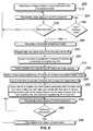
- FIG. 6is a flow chart illustrating, in a first access point, the method for recovering from a failure of a wired link used for communication between the first access point and a wired network, according to an embodiment of the present invention.
- FIG. 7is a flow chart illustrating further details for the selected responding neighboring access point according to an embodiment of the present invention.
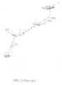
- FIG. 4illustrates an exemplary failure state prior to recovery according to the present invention.
- the wired link between a first access point AP 5 and a backhaul switch 2 of the wired backhaul networkis lost as seen in FIG. 4 , such that there is no path between AP 5 and the wired network.
- the exemplary system shown in FIG. 4is similar to the system shown in FIG. 1 , except that FIG. 4 includes the failure and deploys at least two access points AP 5 and AP 6 operating according to the method of the present invention.
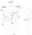
- FIG. 5is an exemplary diagram illustrating aspects of the method and system according to the present invention wherein a communications path to the wired network is provided for any client nodes associated with a first access point in response to detection of loss of the wired link to the first access point by selectively reconfiguring a second radio from an access mode to a backhaul mode.
- a communications path to the wired networkis provided for any client nodes associated with a first access point in response to detection of loss of the wired link to the first access point by selectively reconfiguring a second radio from an access mode to a backhaul mode.
- each access point, AP 5 , and AP 6has at least two radios including a first radio and a second radio each for providing a wireless communications link. Aspects of the method and system illustrated in the example in FIG. 5 are further described in a flow chart in FIG. 6 .
- FIG. 6is a flow chart 200 illustrating, in a first access point, the method for recovering from a failure of a wired link used for communication between the first access point and a wired network, according to the present invention.
- each radio in the first access pointe.g., AP 5 in FIG. 5
- the access modeis for enabling a communications path with a corresponding client node 8 and 12 to enable each one to have a communication path via AP 5 to the wired network.
- the first radio of AP 5operates preferably at 2.4 GHz in accordance with 11b/g and is enabled to be associated with a first client node 8 , as shown in FIG.
- a second radio of AP 5is enabled to be associated with a second client node 12 and operates preferably at 5 GHz in accordance with 11a.
- one or more of the radiosmay be operated in accordance with other suitable protocols including, but not limited to, 802.11n.
- the selectively configuring of the first and second radios of the first access point AP 5 in the access modeenables each corresponding client node 8 and 12 to have a communication path via AP 5 to the wired network, i.e., via Ethernet link Eth 0 and backhaul switch 2 .
- the methodwill be described in further detail regarding the exemplary failure that resulted in loss of the wired link Eth 0 to a first access point AP 5 shown in FIG. 5 .
- the first access pointperiodically checks the status of the first access point's wired link.
- the wired linkis an Ethernet link and the first access point AP 5 has an Ethernet port for providing a physical link to the Ethernet link Eth 0 .
- the Ethernet porthas a link status indicative of the status of the wired link, and the link status is obtained by the first access point which determines therefrom whether the wired link is lost.
- the Ethernet port of the first access point AP 5is at one end of the Ethernet link Eth 0 and a switch 2 is at the other end.
- the switch 2may be a gateway switch, also referred to herein as a gateway, which has an Internet Protocol (IP) address.
- IPInternet Protocol
- the gateway switchmight alternatively be a different switch several hops away from the first access point AP 5 , e.g., switch 6 in FIG. 5 .
- the method according to an embodiment of the present inventiondetects the loss of the connection, i.e., the wired link, between the first access point AP 5 and the gateway.
- the gatewayis switch 6
- a cause of the loss of the wired link between the first access point AP 5 and the gatewaycould be due to a failure anywhere along the connection therebetween, e.g., between switch 2 and switch 6 .
- the gateway switchalso has a physical machine address on the network that is referred to as the Media Access Control (MAC) address. Both the IP and MAC addresses are recognizable by the Ethernet protocol.
- the first access point AP 1detects the loss of the wired link by a method including tracking the gateway switch's IP or MAC address by periodically requesting the switch's address using the Ethernet link and determining whether the address was received in response.
- the periodic requestsmay include transmitting an echo message.
- the echo messagemay be a Packet Internet Groper (PING) command.
- An Address Resolution Protocol (ARP) commandmay alternatively be used if the gateway switch is in the same subnet, i.e., their IP address have the same prefix, as the first access point or if the tracking is based on the switch's MAC address.
- ARPAddress Resolution Protocol
- CDPCisco Discovery Protocol
- LLDPLink Layer Discovery Protocol
- the CDPis a proprietary network protocol used by CISCO routers and switches to perform automatic neighbor discovery.
- the LLDPrefers to the IEEE standard 802.1AB protocol that allows an Ethernet network device to advertise its identity and capabilities on the local network.
- Step 230a determination is made whether the wired link is lost, indicating there may be failure. The process proceeds back to Step 220 if the loss is not detected.
- Step 240a determination is made whether the wired link is lost for greater than a predetermined minimum time, if a loss is detected.
- the loss of the wired linkmust occur for a predetermined minimum time sufficient to determine that the loss is due to a failure for which recovery is needed.
- the predetermined timeis one to two seconds.
- the periodic check in Step 220is performed again if the loss does not exceed the minimum time.
- Step 246is executed if it is detected that the wired link is lost for more than the predetermined minimum time.
- Step 246the second radio of the first access point is reconfigured in a backhaul mode in response to the detection of the loss of the wired link for greater than the predetermined minimum time.
- the second radio of AP 5 in the example in FIG. 5is switched from the access mode to the backhaul mode.
- Step 250is the first step in reconfiguring the second radio in backhaul mode.
- any client nodesare disassociated from the second radio of the first access point, AP 5 . This is illustrated in the example in FIG. 6 , where the 11a radio of AP 5 has been disassociated from client node 12 .
- the method of the present inventionincludes detecting a neighboring access point which can provide a link to the wired network for the first access point AP 5 .
- the first step in this detecting of a neighboring access point, Step 260includes causing the second radio of AP 5 to broadcast a request for backhaul connectivity to neighboring APs.
- the second radiobroadcasts the request preferably at its highest power and on all available channel bands.
- Step 270the first access point AP 5 detects whether any neighboring AP responds to the backhaul connectivity request.
- the first access point AP 5selects a responding neighboring AP based on at least one predetermined criteria.
- the predetermined criteriainclude at least whether there is a communications path via the responding neighboring AP to the wired network.
- neighboring access point AP 6is one of the access points that responded to the backhaul connectivity request sent from the second radio of AP 5 . Both the request from AP 5 and the response from AP 6 are sent on the 11a wireless connection between AP 5 and AP 6 in the example. Alternatively, other suitable protocols including, but not limited to, 802.11n, may be used. As can be seen in FIG. 5 , AP 6 has a communications path on wired link Eth 1 to switch 2 of the wired network; therefore, AP 6 meets at least one of the preferred predetermined criteria in Step 280 .
- the predetermined criteria in Step 280also include that the power of the signal received from the neighboring access point exceeds a predetermined threshold, and the signal power of the signal received by the neighboring access point exceeds a predetermined threshold, in order to ensure that the transmission between the two access points meets a predetermined threshold.
- the predetermined criteriaalso include a requirement that AP 5 and the responding neighboring access point must have the same identification code and password.
- the identification code and password of the neighboring access pointis determined from the response to the backhaul connectivity request.
- Step 290the second radio of AP 5 is caused to provide a wireless link to the selected neighboring AP AP 6 .
- the wireless linkenables AP 5 to detect the wired network connected to AP 6 .
- the wireless linkis the 11a connection between AP 5 and neighboring AP 6 .
- FIG. 5is exemplary only; the neighboring access point might be another access point that provides path to the wired network.
- the communication between the two access pointsis not limited to 11a as shown in FIG. 5 ; other suitable protocols may be used to practice the invention such as 11b/g, 11n, etc.
- Step 292after the selecting in Step 280 , the first access point is caused to enable any client nodes associated with its first radio and any client nodes that had been associated with its second radio to have a communication path to the wired network via a first radio wireless link, a second radio wireless link, and selected neighboring access point's wired link.
- AP 5is caused to enable client node 8 associated with the first radio to have a communications path to switch 4 of the wired network via the first radio 11b/g wireless link, the second radio 11a wireless link to selected neighboring access point AP 6 , and the selected neighboring access point AP 6 's Eth 1 wired link.
- Client node 12 in FIG. 5has been associated with the second radio of AP 5 prior to the disassociation in Step 250 .
- AP 5is caused to enable client node 12 that had been associated with the second radio to be associated with the first radio via the first radio's 11b/g wireless link. That is, in the example in FIG. 5 , client nodes 8 and 12 are both associated with the first radio.
- AP 5is caused, in Step 292 , to enable client node 12 that had been associated with the second radio to have a communications path to the wired network via the first radio 11b/g wireless link, the second radio 11a wireless link to selected neighboring access point AP 6 , and the selected neighboring access point AP 6 's Eth 1 wired link to the wired network.
- the link between AP 5 and AP 6 and the link between AP 6 and the wired networktherefore, provide a backhaul wireless link for client nodes 8 and 12 via AP 5 .
- the recovery process steps from detecting the loss for greater than a minimum time in Step 240 to Step 292is preferably completed in five to fifteen seconds.
- Step 294the first access point AP 5 periodically checks the status of its wired link to the wired network. The check may be done by any of the methods described above with regard to Step 220 .
- Step 296A determination is made in Step 296 , based on the periodic status checks in Step 294 , whether the wired link has recovered such that it can again provide the wired link between the access point and the backhaul network, i.e., between AP 5 and switch 2 in the example shown in FIG. 5 .
- the recoverymust be for a predetermined minimum time.
- Step 294the process proceeds to Step 294 if recovery of the wired link is not detected in Step 296 .
- the exemplary processproceeds to Step 298 .
- Step 298the second radio of the first access point is selectively reconfigured in the access mode.
- the second radio of AP 5is selectively reconfigured in the access mode from the backhaul mode shown in FIG. 5 .
- the second radioconnected of AP 5 connected to AP 6 via the 11a connection.
- the second radio reconfigured in the access modeis enabled to be associated with the second client node, node 12 in FIG. 5 . That is, in response to detection of recovery of the wired link between the first access point and the wired network, the first access point is configured again in an access mode as shown in FIG. 4 , i.e., with the wired Etho link recovered.
- FIG. 7is a flow chart 300 illustrating further details for the selected responding neighboring access point according to an embodiment of the present invention.
- AP 6 in FIG. 5is the selected neighboring access point in FIG. 6 .
- the neighboring access point AP 6preferably includes a first and second radio.
- Step 310prior to selection in Step 280 in FIG. 6 , each of the at least two radios of AP 6 is selectively configured in an access mode for enabling a communications path with a corresponding client node 14 and 16 to enable each one to have a communication path via AP 6 to the wired network.
- the first radio of AP 6operates preferably at 2.4 GHz in accordance with 11b/g and is enabled to be associated with a first client node 16 , as shown in FIG. 4 .
- a second radio of AP 6is enabled to be associated with a second client node 14 and operates preferably at 5 GHz in accordance with 11a as shown in FIG. 4 .
- one or more of the radiosmay be operated in accordance with other suitable protocols including, but not limited to, 802.11n.
- the selectively configuring of the first and second radios of the neighboring access point AP 6 in the access modeenables each corresponding client node 14 and 16 to have a communication path via AP 6 to the wired network, i.e., via Ethernet link Eth 1 and switch 4 , in FIG. 4 .
- Step 320in response to receipt of a backhaul connectivity request from the first access point Ap 5 , the neighboring access point AP 6 responds to the backhaul connectivity request.
- Step 330the neighboring access point AP 6 determines whether it has been selected by the first access point to provide the wireless backhaul link.
- AP 6In response to its selection as the responding neighboring AP, AP 6 reconfigures its second radio to a backhaul mode in Step 340 .
- Step 350is the first step in reconfiguring the second radio of selected neighboring AP 6 in backhaul mode.
- any client nodesare disassociated from the second radio of the neighboring access point Ap 6 . This is illustrated in the example in FIG. 5 , where the 11a radio of AP 6 which as been associated with client node 14 in the access mode as seen in FIG. 4 , has been disassociated from client node 14 .
- Step 360the neighboring access point AP 6 caused its second radio to enable a wireless link to the first access point AP 5 , i.e., with the first access point AP 5 's second radio.
- Step 370the neighboring access point is caused to enable any client nodes that had been associated with its second radio to be associated with the first radio to provide a communication path to the wired network via a first radio wireless link and AP 6 's wired link.
- the communications path that enables both client nodes 14 and 16 to connect to AP 6is 11b/g and the first radio.
- Step 380a periodic check is made regarding whether the access point AP 5 has been reconfigured in an access mode in response to recovery of the wired link to AP 5 .
- Step 390a determination is made based on the periodic check in Step 380 whether the first access point has been reconfigured in an access mode in response to recovery of the wired link to the first access point (in Step 296 of FIG. 6 ).
- the access point AP 5 and the neighboring access point AP 6periodically exchange messages to indicate failover status.
- Access point AP 6preferably detects the reconfiguration of access point AP 5 in an access mode based on the status received. The process returns to Step 380 in response to determining that the first access point AP 5 has not been reconfigured in an access mode.
- Step 392the second radio of the neighboring access point AP 6 is selectively reconfigured in an access mode. That is, in response to detecting that the access point AP 5 has been reconfigured in an access mode in response to recovery of the wired link to AP 5 , the second access point AP 6 is configured again in an access mode as shown in the example in FIG. 4 , however, with the wired Eth 0 link recovered.
- the reconfiguration in an access modeis made a predetermined minimum time after the detection that access point AP 5 has been reconfigured in an access mode.
- Step 392the process proceeds back to Step 320 .
Landscapes
- Engineering & Computer Science (AREA)
- Computer Networks & Wireless Communication (AREA)
- Signal Processing (AREA)
- Mobile Radio Communication Systems (AREA)
Abstract
Description
Claims (21)
Priority Applications (1)
| Application Number | Priority Date | Filing Date | Title |
|---|---|---|---|
| US12/070,863US7839771B2 (en) | 2008-02-21 | 2008-02-21 | Backhaul failover method and system for a wireless network |
Applications Claiming Priority (1)
| Application Number | Priority Date | Filing Date | Title |
|---|---|---|---|
| US12/070,863US7839771B2 (en) | 2008-02-21 | 2008-02-21 | Backhaul failover method and system for a wireless network |
Publications (2)
| Publication Number | Publication Date |
|---|---|
| US20090213730A1 US20090213730A1 (en) | 2009-08-27 |
| US7839771B2true US7839771B2 (en) | 2010-11-23 |
Family
ID=40998182
Family Applications (1)
| Application Number | Title | Priority Date | Filing Date |
|---|---|---|---|
| US12/070,863Active2028-06-24US7839771B2 (en) | 2008-02-21 | 2008-02-21 | Backhaul failover method and system for a wireless network |
Country Status (1)
| Country | Link |
|---|---|
| US (1) | US7839771B2 (en) |
Cited By (8)
| Publication number | Priority date | Publication date | Assignee | Title |
|---|---|---|---|---|
| US20120002537A1 (en)* | 2010-06-30 | 2012-01-05 | Cellco Partnership | Base station failover using neighboring base stations as relays |
| US20120026865A1 (en)* | 2010-07-28 | 2012-02-02 | At&T Intellectual Property I, L.P. | Femtocell service through a secondary connection |
| US8254943B1 (en)* | 2008-12-22 | 2012-08-28 | Sprint Communications Company L.P. | Method for backhaul transport recovery |
| US20120287774A1 (en)* | 2010-04-01 | 2012-11-15 | Hinkle Lee B | Power and connectivity aware switch |
| KR20150028333A (en)* | 2012-06-29 | 2015-03-13 | 톰슨 라이센싱 | A device and a method at the device for configuring a wireless interface |
| US10848377B2 (en) | 2019-01-28 | 2020-11-24 | Hewlett Packard Enterprise Development Lp | Access point instantiation of a mesh network |
| US11026285B2 (en) | 2019-04-03 | 2021-06-01 | At&T Intellectual Property I, L.P. | Systems and methods for establishing network connections |
| US11283644B2 (en)* | 2020-03-04 | 2022-03-22 | At&T Intellectual Property I, L.P. | Facilitation of access point authenticated tunneling for 5G or other next generation network |
Families Citing this family (46)
| Publication number | Priority date | Publication date | Assignee | Title |
|---|---|---|---|---|
| US8638708B2 (en) | 2004-11-05 | 2014-01-28 | Ruckus Wireless, Inc. | MAC based mapping in IP based communications |
| US9240868B2 (en) | 2004-11-05 | 2016-01-19 | Ruckus Wireless, Inc. | Increasing reliable data throughput in a wireless network |
| US8619662B2 (en) | 2004-11-05 | 2013-12-31 | Ruckus Wireless, Inc. | Unicast to multicast conversion |
| US7505447B2 (en) | 2004-11-05 | 2009-03-17 | Ruckus Wireless, Inc. | Systems and methods for improved data throughput in communications networks |
| US8547899B2 (en) | 2007-07-28 | 2013-10-01 | Ruckus Wireless, Inc. | Wireless network throughput enhancement through channel aware scheduling |
| US8355343B2 (en) | 2008-01-11 | 2013-01-15 | Ruckus Wireless, Inc. | Determining associations in a mesh network |
| US11477721B2 (en)* | 2008-02-22 | 2022-10-18 | Qualcomm Incorporated | Methods and apparatus for controlling transmission of a base station |
| US20100110877A1 (en)* | 2008-10-30 | 2010-05-06 | Symbol Technologies, Inc. | System and method for failover of mobile units in a wireless network |
| JP2010252243A (en)* | 2009-04-20 | 2010-11-04 | Buffalo Inc | Network relay device and method for controlling network relay device |
| US8089354B2 (en)* | 2009-10-08 | 2012-01-03 | Awarepoint Corporation | Wireless tracking system and method for backhaul of information |
| US8811152B2 (en)* | 2009-10-29 | 2014-08-19 | At&T Intellectual Property I, L.P. | System and method to support secondary channel connection from residential gateway to service provider network |
| WO2011060454A2 (en)* | 2009-11-16 | 2011-05-19 | Ruckus Wireless, Inc. | Establishing a mesh network with wired and wireless links |
| US9979626B2 (en) | 2009-11-16 | 2018-05-22 | Ruckus Wireless, Inc. | Establishing a mesh network with wired and wireless links |
| US8358577B1 (en)* | 2009-12-10 | 2013-01-22 | Sprint Communications Company L.P. | Using wireless links to offload backhaul communications |
| US20110182172A1 (en)* | 2010-01-26 | 2011-07-28 | Sudarshan Kulkarni | Auto Mesh Discovery Mechanism |
| JP4989745B2 (en)* | 2010-03-29 | 2012-08-01 | 株式会社バッファロー | Apparatus, method, and program for relaying communication |
| ES2377686B1 (en) | 2010-05-31 | 2013-02-13 | Vodafone España, S.A.U. | METHOD FOR MODIFYING THE FREQUENCY CONFIGURATION OF A BASE STATION OF FEMTOCELL 3G OR NODE-B DOMESTIC (HNB). |
| US8498201B2 (en)* | 2010-08-26 | 2013-07-30 | Honeywell International Inc. | Apparatus and method for improving the reliability of industrial wireless networks that experience outages in backbone connectivity |
| US8457656B2 (en) | 2010-09-27 | 2013-06-04 | Awarepoint Corporation | Wireless tracking system and method utilizing multiple location algorithms |
| KR101941281B1 (en)* | 2011-05-03 | 2019-01-22 | 한국전자통신연구원 | Method for communication of base station and terminal |
| US20130065634A1 (en)* | 2011-09-09 | 2013-03-14 | Electronics And Telecommunications Research Institute | Method for communication of terminal and method for communication of base station |
| US9014023B2 (en) | 2011-09-15 | 2015-04-21 | International Business Machines Corporation | Mobile network services in a mobile data network |
| US8717872B2 (en) | 2011-11-16 | 2014-05-06 | International Business Machines Corporation | Fail to wire removable module for network communication link |
| US8724455B2 (en)* | 2012-01-20 | 2014-05-13 | International Business Machines Corporation | Distributed control of a fail-to-wire switch for a network communication link |
| US10708121B2 (en) | 2012-11-05 | 2020-07-07 | Comcast Cable Communications, Llc | Intelligent network |
| EP2739081A1 (en)* | 2012-11-29 | 2014-06-04 | British Telecommunications public limited company | Network access restoration |
| EP2739093A1 (en) | 2012-11-29 | 2014-06-04 | British Telecommunications public limited company | Restoration of network access |
| CN103916295B (en)* | 2012-12-31 | 2017-09-12 | 华为终端有限公司 | Data transmission method, equipment and gateway |
| US9078157B2 (en)* | 2012-12-31 | 2015-07-07 | Verizon Patent And Licensing Inc. | Quick recovery of RF sessions after backhaul link failure |
| US9642146B2 (en)* | 2013-06-05 | 2017-05-02 | Huawei Technologies Co., Ltd. | System and method for an agile wireless access network |
| US9306839B2 (en)* | 2013-07-22 | 2016-04-05 | Symbol Technologies, Llc | IEEE 802.11U failover for a mesh network |
| EP2869629B1 (en)* | 2013-10-31 | 2017-06-07 | Telefonica Digital España, S.L.U. | Method and device for coordinating access points for backhaul aggregation in a telecommunications network |
| EP2871804B1 (en)* | 2013-11-11 | 2017-02-01 | Telefonica Digital España, S.L.U. | A method for access points scheduling for backhaul aggregation in a telecommunications network and a device |
| DE102014210336A1 (en)* | 2014-04-25 | 2015-11-12 | Power Plus Communications Ag | Headend as well as system and procedure for the failure-tolerant connection of broadband powerline terminals by means of this headend to a backbone network |
| CN107211477B (en) | 2015-02-13 | 2019-08-30 | 英国电讯有限公司 | Wireless communication device, method of operation thereof, and computer-readable storage medium |
| US10158463B1 (en)* | 2015-03-17 | 2018-12-18 | Sprint Spectrum L.P. | Method and system for coordinated transmission with use of neighboring base station scheduling policy |
| US9867226B2 (en) | 2015-12-14 | 2018-01-09 | Qualcomm Incorporated | Radio link failure (RLF) failover in a multi-connectivity environment |
| JP6538639B2 (en)* | 2016-11-22 | 2019-07-03 | Necプラットフォームズ株式会社 | Wireless communication device, method and program |
| US11277195B2 (en) | 2017-04-27 | 2022-03-15 | Airspan Ip Holdco Llc | Apparatus and method for providing network coverage in a wireless network |
| US10721669B2 (en)* | 2017-04-27 | 2020-07-21 | Airspan Networks, Inc. | Apparatus and method for improving connectivity for items of user equipment in a wireless network |
| US10607012B2 (en) | 2017-12-29 | 2020-03-31 | Delphian Systems, LLC | Bridge computing device control in local networks of interconnected devices |
| WO2019163645A1 (en)* | 2018-02-22 | 2019-08-29 | Kddi株式会社 | Control device for cellular communication network in which relayed communication is performed, base station device, terminal device, control methods therefor, and program |
| US20200137620A1 (en)* | 2018-10-25 | 2020-04-30 | Institute For Information Industry | Wireless communication system and method for redirecting multimedia broadcast/multicast service data |
| US10887795B2 (en)* | 2018-12-13 | 2021-01-05 | Fortinet, Inc. | Over-the-air (OTA) Wi-Fi offloading |
| US11638319B2 (en)* | 2019-02-12 | 2023-04-25 | Samsung Electronics Co., Ltd. | Handling radio link failure in cellular mesh networks |
| US12192799B2 (en)* | 2021-10-06 | 2025-01-07 | Hewlett Packard Enterprise Development Lp | Autonomous access point failure recovery |
Citations (11)
| Publication number | Priority date | Publication date | Assignee | Title |
|---|---|---|---|---|
| US20020091813A1 (en)* | 2000-11-14 | 2002-07-11 | International Business Machines Corporation | Enabling surveillance of network connected device |
| US20050099983A1 (en)* | 2003-11-10 | 2005-05-12 | Nobuyuki Nakamura | Communication terminal and communication network |
| US7057566B2 (en) | 2004-01-20 | 2006-06-06 | Cisco Technology, Inc. | Flexible multichannel WLAN access point architecture |
| US7085224B1 (en) | 2001-06-14 | 2006-08-01 | Cisco Technology, Inc. | Method and apparatus for fast failure detection in switched LAN networks |
| US7164667B2 (en) | 2002-06-28 | 2007-01-16 | Belair Networks Inc. | Integrated wireless distribution and mesh backhaul networks |
| US7181530B1 (en) | 2001-07-27 | 2007-02-20 | Cisco Technology, Inc. | Rogue AP detection |
| US20070078663A1 (en) | 2003-03-03 | 2007-04-05 | Grace Ryan T | Method and instrument for proposing marriage to an individual |
| US20070140191A1 (en) | 2005-12-16 | 2007-06-21 | Fujitsu Limited | Wireless LAN device and communication mode switching method |
| US7251238B2 (en) | 2004-09-07 | 2007-07-31 | Meshnetworks, Inc. | System and method for routing data between different types of nodes in a wireless network |
| US20080090575A1 (en)* | 2006-07-13 | 2008-04-17 | Oz Barak | WiMAX ACCESS POINT NETWORK WITH BACKHAUL TECHNOLOGY |
| US20080170527A1 (en)* | 2007-01-11 | 2008-07-17 | Motorola, Inc. | Changing access point (ap) device type based on connectivity to a network |
- 2008
- 2008-02-21USUS12/070,863patent/US7839771B2/enactiveActive
Patent Citations (11)
| Publication number | Priority date | Publication date | Assignee | Title |
|---|---|---|---|---|
| US20020091813A1 (en)* | 2000-11-14 | 2002-07-11 | International Business Machines Corporation | Enabling surveillance of network connected device |
| US7085224B1 (en) | 2001-06-14 | 2006-08-01 | Cisco Technology, Inc. | Method and apparatus for fast failure detection in switched LAN networks |
| US7181530B1 (en) | 2001-07-27 | 2007-02-20 | Cisco Technology, Inc. | Rogue AP detection |
| US7164667B2 (en) | 2002-06-28 | 2007-01-16 | Belair Networks Inc. | Integrated wireless distribution and mesh backhaul networks |
| US20070078663A1 (en) | 2003-03-03 | 2007-04-05 | Grace Ryan T | Method and instrument for proposing marriage to an individual |
| US20050099983A1 (en)* | 2003-11-10 | 2005-05-12 | Nobuyuki Nakamura | Communication terminal and communication network |
| US7057566B2 (en) | 2004-01-20 | 2006-06-06 | Cisco Technology, Inc. | Flexible multichannel WLAN access point architecture |
| US7251238B2 (en) | 2004-09-07 | 2007-07-31 | Meshnetworks, Inc. | System and method for routing data between different types of nodes in a wireless network |
| US20070140191A1 (en) | 2005-12-16 | 2007-06-21 | Fujitsu Limited | Wireless LAN device and communication mode switching method |
| US20080090575A1 (en)* | 2006-07-13 | 2008-04-17 | Oz Barak | WiMAX ACCESS POINT NETWORK WITH BACKHAUL TECHNOLOGY |
| US20080170527A1 (en)* | 2007-01-11 | 2008-07-17 | Motorola, Inc. | Changing access point (ap) device type based on connectivity to a network |
Cited By (16)
| Publication number | Priority date | Publication date | Assignee | Title |
|---|---|---|---|---|
| US8254943B1 (en)* | 2008-12-22 | 2012-08-28 | Sprint Communications Company L.P. | Method for backhaul transport recovery |
| US9030923B2 (en)* | 2010-04-01 | 2015-05-12 | Hewlett-Packard Development Company, L.P. | Power and connectivity aware switch |
| US20120287774A1 (en)* | 2010-04-01 | 2012-11-15 | Hinkle Lee B | Power and connectivity aware switch |
| US9749880B2 (en)* | 2010-06-30 | 2017-08-29 | Verizon Patent And Licensing Inc. | Base station failover using neighboring base stations as relays |
| US20120002537A1 (en)* | 2010-06-30 | 2012-01-05 | Cellco Partnership | Base station failover using neighboring base stations as relays |
| US9474076B2 (en) | 2010-07-28 | 2016-10-18 | At&T Intellectual Property I, L.P. | Femtocell service through a secondary connection |
| US8750098B2 (en)* | 2010-07-28 | 2014-06-10 | At&T Intellectual Property I, L.P. | Femtocell service through a secondary connection |
| US20120026865A1 (en)* | 2010-07-28 | 2012-02-02 | At&T Intellectual Property I, L.P. | Femtocell service through a secondary connection |
| US9942783B2 (en) | 2010-07-28 | 2018-04-10 | At&T Intellectual Property I, L.P. | Femtocell service through a secondary connection |
| KR20150028333A (en)* | 2012-06-29 | 2015-03-13 | 톰슨 라이센싱 | A device and a method at the device for configuring a wireless interface |
| US20150156063A1 (en)* | 2012-06-29 | 2015-06-04 | Thomson Licensing | Device and a method at the device for configuring a wireless interface |
| US9729393B2 (en)* | 2012-06-29 | 2017-08-08 | Thomson Licensing | Device and a method at the device for configuring a wireless interface |
| US10848377B2 (en) | 2019-01-28 | 2020-11-24 | Hewlett Packard Enterprise Development Lp | Access point instantiation of a mesh network |
| US11026285B2 (en) | 2019-04-03 | 2021-06-01 | At&T Intellectual Property I, L.P. | Systems and methods for establishing network connections |
| US11665768B2 (en) | 2019-04-03 | 2023-05-30 | At&T Intellectual Property I, L.P. | Systems and methods for establishing network connections |
| US11283644B2 (en)* | 2020-03-04 | 2022-03-22 | At&T Intellectual Property I, L.P. | Facilitation of access point authenticated tunneling for 5G or other next generation network |
Also Published As
| Publication number | Publication date |
|---|---|
| US20090213730A1 (en) | 2009-08-27 |
Similar Documents
| Publication | Publication Date | Title |
|---|---|---|
| US7839771B2 (en) | Backhaul failover method and system for a wireless network | |
| US8248949B2 (en) | Method and device for providing an alternative backhaul portal in a mesh network | |
| US7965681B2 (en) | Channel allocation procedure in a meshed network | |
| EP2243313B1 (en) | Coordinated channel change in mesh networks | |
| KR100590866B1 (en) | Wireless terminal registration method and apparatus thereof for access point through wireless network | |
| US8675622B2 (en) | Self-configurable wireless local area network node | |
| CN101286909B (en) | Method of automatically constructing wireless distributed system | |
| US10645755B2 (en) | Communication system, communication device, and communication control method | |
| US11523324B2 (en) | Method for configuring a wireless communication coverage extension system and a wireless communication coverage extension system implementing said method | |
| WO2010095028A2 (en) | Maximum transmission unit (mtu) size discovery mechanism and method for data-link layers | |
| JP4930451B2 (en) | Base station apparatus, base station management apparatus, and base station management system | |
| WO2006071289A1 (en) | Method and system for recovery from access point infrastructure link failures | |
| CN113347645A (en) | 802.11 wireless multi-hop communication and self-adaptive switching method | |
| CN117676771A (en) | Multimode fusion 5G network access method | |
| TW202437786A (en) | Dynamic path selection techniques for wireless connectivity | |
| US9877348B2 (en) | Method and apparatus for establishing a backhaul link | |
| CN101237682A (en) | Wireless network system and its connection method | |
| US12192799B2 (en) | Autonomous access point failure recovery | |
| JP7720045B1 (en) | Method and apparatus for adaptive mesh network configuration | |
| US12356317B2 (en) | Mm wave communication mesh network | |
| CN119653397A (en) | A communication recovery method and related device for link failure | |
| CN120814214A (en) | Dynamic path selection techniques for wireless connections | |
| KR20190094069A (en) | A method for self-organizination networking (son) in internet of things (iot) and an apparatus performing the same | |
| JP2020198519A (en) | Wireless relay device and wireless lan system using the same and wireless relay method | |
| CN105848246A (en) | Asynchronous TDMA neighbor node scanning method in Ad HOC Network |
Legal Events
| Date | Code | Title | Description |
|---|---|---|---|
| AS | Assignment | Owner name:AEROHIVE NETWORKS, CALIFORNIA Free format text:ASSIGNMENT OF ASSIGNORS INTEREST;ASSIGNORS:ZENG, JIANLIN;LIU, CHANGMING;REEL/FRAME:020653/0147 Effective date:20080313 | |
| STCF | Information on status: patent grant | Free format text:PATENTED CASE | |
| FEPP | Fee payment procedure | Free format text:PAT HOLDER NO LONGER CLAIMS SMALL ENTITY STATUS, ENTITY STATUS SET TO UNDISCOUNTED (ORIGINAL EVENT CODE: STOL); ENTITY STATUS OF PATENT OWNER: LARGE ENTITY | |
| FPAY | Fee payment | Year of fee payment:4 | |
| MAFP | Maintenance fee payment | Free format text:PAYMENT OF MAINTENANCE FEE, 8TH YEAR, LARGE ENTITY (ORIGINAL EVENT CODE: M1552) Year of fee payment:8 | |
| AS | Assignment | Owner name:BANK OF MONTREAL, NEW YORK Free format text:SECURITY INTEREST;ASSIGNORS:EXTREME NETWORKS, INC.;AEROHIVE NETWORKS, INC.;REEL/FRAME:050023/0001 Effective date:20190809 | |
| AS | Assignment | Owner name:EXTREME NETWORKS, INC., CALIFORNIA Free format text:ASSIGNMENT OF ASSIGNORS INTEREST;ASSIGNOR:AEROHIVE NETWORKS, INC.;REEL/FRAME:052473/0843 Effective date:20200130 | |
| MAFP | Maintenance fee payment | Free format text:PAYMENT OF MAINTENANCE FEE, 12TH YEAR, LARGE ENTITY (ORIGINAL EVENT CODE: M1553); ENTITY STATUS OF PATENT OWNER: LARGE ENTITY Year of fee payment:12 | |
| AS | Assignment | Owner name:BANK OF MONTREAL, NEW YORK Free format text:AMENDED SECURITY AGREEMENT;ASSIGNORS:EXTREME NETWORKS, INC.;AEROHIVE NETWORKS, INC.;REEL/FRAME:064782/0971 Effective date:20230818 |