US7837947B2 - Sample mixing on a microfluidic device - Google Patents
Sample mixing on a microfluidic deviceDownload PDFInfo
- Publication number
- US7837947B2 US7837947B2US10/734,682US73468203AUS7837947B2US 7837947 B2US7837947 B2US 7837947B2US 73468203 AUS73468203 AUS 73468203AUS 7837947 B2US7837947 B2US 7837947B2
- Authority
- US
- United States
- Prior art keywords
- mixing
- process chamber
- sample
- chamber
- processing device
- Prior art date
- Legal status (The legal status is an assumption and is not a legal conclusion. Google has not performed a legal analysis and makes no representation as to the accuracy of the status listed.)
- Active, expires
Links
Images


Classifications
- B—PERFORMING OPERATIONS; TRANSPORTING
- B01—PHYSICAL OR CHEMICAL PROCESSES OR APPARATUS IN GENERAL
- B01L—CHEMICAL OR PHYSICAL LABORATORY APPARATUS FOR GENERAL USE
- B01L3/00—Containers or dishes for laboratory use, e.g. laboratory glassware; Droppers
- B01L3/50—Containers for the purpose of retaining a material to be analysed, e.g. test tubes
- B01L3/502—Containers for the purpose of retaining a material to be analysed, e.g. test tubes with fluid transport, e.g. in multi-compartment structures
- B01L3/5027—Containers for the purpose of retaining a material to be analysed, e.g. test tubes with fluid transport, e.g. in multi-compartment structures by integrated microfluidic structures, i.e. dimensions of channels and chambers are such that surface tension forces are important, e.g. lab-on-a-chip
- B01L3/502738—Containers for the purpose of retaining a material to be analysed, e.g. test tubes with fluid transport, e.g. in multi-compartment structures by integrated microfluidic structures, i.e. dimensions of channels and chambers are such that surface tension forces are important, e.g. lab-on-a-chip characterised by integrated valves
- B—PERFORMING OPERATIONS; TRANSPORTING
- B01—PHYSICAL OR CHEMICAL PROCESSES OR APPARATUS IN GENERAL
- B01F—MIXING, e.g. DISSOLVING, EMULSIFYING OR DISPERSING
- B01F33/00—Other mixers; Mixing plants; Combinations of mixers
- B01F33/30—Micromixers
- B—PERFORMING OPERATIONS; TRANSPORTING
- B01—PHYSICAL OR CHEMICAL PROCESSES OR APPARATUS IN GENERAL
- B01F—MIXING, e.g. DISSOLVING, EMULSIFYING OR DISPERSING
- B01F35/00—Accessories for mixers; Auxiliary operations or auxiliary devices; Parts or details of general application
- B01F35/71—Feed mechanisms
- B01F35/712—Feed mechanisms for feeding fluids
- B—PERFORMING OPERATIONS; TRANSPORTING
- B01—PHYSICAL OR CHEMICAL PROCESSES OR APPARATUS IN GENERAL
- B01F—MIXING, e.g. DISSOLVING, EMULSIFYING OR DISPERSING
- B01F35/00—Accessories for mixers; Auxiliary operations or auxiliary devices; Parts or details of general application
- B01F35/71—Feed mechanisms
- B01F35/717—Feed mechanisms characterised by the means for feeding the components to the mixer
- B01F35/71725—Feed mechanisms characterised by the means for feeding the components to the mixer using centrifugal forces
- B—PERFORMING OPERATIONS; TRANSPORTING
- B01—PHYSICAL OR CHEMICAL PROCESSES OR APPARATUS IN GENERAL
- B01L—CHEMICAL OR PHYSICAL LABORATORY APPARATUS FOR GENERAL USE
- B01L2300/00—Additional constructional details
- B01L2300/08—Geometry, shape and general structure
- B01L2300/0803—Disc shape
- B01L2300/0806—Standardised forms, e.g. compact disc [CD] format
- B—PERFORMING OPERATIONS; TRANSPORTING
- B01—PHYSICAL OR CHEMICAL PROCESSES OR APPARATUS IN GENERAL
- B01L—CHEMICAL OR PHYSICAL LABORATORY APPARATUS FOR GENERAL USE
- B01L2400/00—Moving or stopping fluids
- B01L2400/04—Moving fluids with specific forces or mechanical means
- B01L2400/0403—Moving fluids with specific forces or mechanical means specific forces
- B01L2400/0409—Moving fluids with specific forces or mechanical means specific forces centrifugal forces
- B—PERFORMING OPERATIONS; TRANSPORTING
- B01—PHYSICAL OR CHEMICAL PROCESSES OR APPARATUS IN GENERAL
- B01L—CHEMICAL OR PHYSICAL LABORATORY APPARATUS FOR GENERAL USE
- B01L2400/00—Moving or stopping fluids
- B01L2400/06—Valves, specific forms thereof
- B01L2400/0677—Valves, specific forms thereof phase change valves; Meltable, freezing, dissolvable plugs; Destructible barriers
- Y—GENERAL TAGGING OF NEW TECHNOLOGICAL DEVELOPMENTS; GENERAL TAGGING OF CROSS-SECTIONAL TECHNOLOGIES SPANNING OVER SEVERAL SECTIONS OF THE IPC; TECHNICAL SUBJECTS COVERED BY FORMER USPC CROSS-REFERENCE ART COLLECTIONS [XRACs] AND DIGESTS
- Y10—TECHNICAL SUBJECTS COVERED BY FORMER USPC
- Y10T—TECHNICAL SUBJECTS COVERED BY FORMER US CLASSIFICATION
- Y10T436/00—Chemistry: analytical and immunological testing
- Y10T436/25—Chemistry: analytical and immunological testing including sample preparation
- Y10T436/2575—Volumetric liquid transfer
Definitions
- the present inventionrelates to the mixing of fluid samples in a microfluidic sample processing device.
- Sample processing devicesincluding process chambers in which various chemical or biological processes are performed play an increasing role in scientific and/or diagnostic investigations.
- the process chambers provided in such devicesare preferably small in volume to reduce the amount of sample material required to perform the processes.
- sample processing devicesincluding process chambers. For example, mixing may be useful to improve utilization of reagents and/or sample utilization.
- Many sample processing devicesare, however, designed to use small volumes of sample material (e.g., 5 microliters) that are not easily accessed after loaded into the sample processing devices designed to process such small sample volumes.
- the process chambersmay include exit ports that are also located on the distal side of the process chambers.
- exit portsmay be, e.g., enhanced emptying of the mixing chambers and the process chambers.
- the mixing chambermay be located within the footprint of the process chamber.
- One potential advantage of such a constructionis that the area on the sample processing device occupied by the process chamber and associated mixing structure can be reduced.
- the present inventionprovides a sample mixing structure on a sample processing device, the sample mixing structure including a process chamber with a delivery port on a proximal side of the process chamber and an exit port on a distal side of the process chamber; a mixing chamber with a mixing port, wherein the mixing port is located on the distal side of the process chamber.
- Rotation of the sample processing device about an axis of rotationmoves at least a portion of sample material in the processing chamber into the mixing chamber through the mixing port when the mixing port is open, wherein the proximal side of the process chamber is located closer to the axis of rotation than the distal side of the process chamber.
- the exit port of the process chamberis open, rotation of the sample processing device about the axis of rotation moves the sample material out of the process chamber and the mixing chamber.
- the present inventionprovides sample mixing structure on a sample processing device, the sample mixing structure including a process chamber with a delivery port on a proximal side of the process chamber and an exit port on a distal side of the process chamber, wherein the exit port is closed; and a mixing chamber with a mixing port, wherein the mixing port is located on the distal side of the process chamber.
- the process chamberis located between a first major side and a second major side of the sample processing device, wherein at least a portion of the mixing chamber is located between the process chamber and the second major side of the sample processing device.
- Rotation of the sample processing device about an axis of rotationmoves at least a portion of sample material in the processing chamber into the mixing chamber through the mixing port when the mixing port is open, wherein the proximal side of the process chamber is located closer to the axis of rotation than the distal side of the process chamber.
- rotation of the sample processing device about the axis of rotationmoves the sample material out of the process chamber and the mixing chamber.
- the present inventionprovides sample mixing structure on a sample processing device, the sample mixing structure including a process chamber with a delivery port on a proximal side of the process chamber and an exit port on a distal side of the process chamber; a first mixing chamber in fluid communication with the process chamber through a first mixing port, wherein the first mixing port is located on the distal side of the process chamber; and a second mixing chamber in fluid communication with the process chamber through a second mixing port, wherein the second mixing port is located on the distal side of the process chamber.
- Rotation of the sample processing device about an axis of rotationmoves at least a portion of sample material in the processing chamber into at least one of the first mixing chamber and the second mixing chamber, wherein the proximal side of the process chamber is located closer to the axis of rotation than the distal side of the process chamber.
- rotation of the sample processing device about the axis of rotationmoves the sample material out of the first mixing chamber, the second mixing chamber, and the process chamber.
- the present inventionprovides a method of mixing fluids in a sample processing device.
- the methodincludes providing a sample processing device having a process chamber, at least one mixing chamber, and at least one mixing port located on a distal side of the process chamber; providing sample material in the process chamber; rotating the sample processing device about an axis of rotation, wherein at least a portion of sample material in the processing chamber moves into the at least one mixing chamber through the at least one mixing port when rotating the sample processing device, wherein the rotating comprises two or more acceleration and deceleration cycles.
- the methodalso includes opening an exit port in the process chamber after rotating the sample processing device to move at least a portion of sample material in the processing chamber into the at least one mixing chamber; and removing at least a portion of the sample material from the process chamber through the exit port by rotating the sample processing device about the axis of rotation.
- FIG. 1is a plan view of one exemplary sample processing device according to the present invention.
- FIG. 2is an enlarged view of one exemplary mixing structure and associated process chamber according to the present invention.
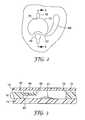
- FIG. 3is an enlarged cross-sectional view of the process chamber of FIG. 2 , taken along line 3 - 3 in FIG. 2 .
- FIGS. 4 & 5depict mixing actions using a process chamber and mixing chamber in one embodiment of the present invention.
- FIG. 6is a perspective view of an alternative process chamber and associated mixing structure according to the present invention.
- FIG. 7is a perspective view of another alternative process chamber and associated mixing structure according to the present invention.
- FIG. 8is an enlarged cross-sectional view of the process chamber and associated mixing structure of FIG. 7 , taken along line 8 - 8 in FIG. 7 .
- the present inventionprovides a sample processing device that can be used in the processing of liquid sample materials (or sample materials entrained in a liquid) in multiple process chambers to obtain desired reactions, e.g., PCR amplification, ligase chain reaction (LCR), self-sustaining sequence replication, enzyme kinetic studies, homogeneous ligand binding assays, and other chemical, biochemical, or other reactions that may, e.g., require precise and/or rapid thermal variations. More particularly, the present invention provides sample processing devices that include one or more process arrays, each of which may preferably include a loading chamber, at least one process chamber, a valve chamber, and conduits for moving fluids between various components of the process arrays.
- desired reactionse.g., PCR amplification, ligase chain reaction (LCR), self-sustaining sequence replication, enzyme kinetic studies, homogeneous ligand binding assays, and other chemical, biochemical, or other reactions that may, e.g., require precise and/or rapid thermal variations.
- sample processing devices of the present inventionmay be similar to those described in, e.g., U.S. Patent Application Publication Nos. US2002/0064885 (Bedingham et al.); US2002/0048533 (Bedingham et al.); US2002/0047003 (Bedingham et al.), and US2003/138779 (Parthasarathy et al.); as well as U.S. Pat. No. 6,627,159 B1 (Bedingham et al.) and U.S. Pat. No. 7,322,254 (Bedingham et al.).
- the documents identified aboveall disclose a variety of different constructions of sample processing devices that could be used to manufacture sample processing devices according to the principles of the present invention.
- FIG. 1is a plan view of one sample processing device 10 that may include process chambers and associated mixing structures of the present invention.
- the sample processing device 10may preferably be in the shape of a circular disc as illustrated in FIG. 1 , although any other shape that can be rotated could be used in place of a circular disc, e.g., rectangular, etc.
- the sample processing device 10includes at least one process array 20 as seen in FIG. 1 . In other embodiments, it may be preferred that the sample processing device 10 include two or more process arrays 20 . If the sample processing device 10 is circular as depicted, it may be preferred that each of the depicted process array 20 includes components that are aligned with a radial axis 21 extending from proximate a center 12 of the sample processing device 10 towards the periphery of the sample processing device 10 . Although this arrangement may be preferred, it will be understood that any arrangement of process arrays 20 on sample processing device 10 may alternatively be used.
- the sample processing device 10is designed to be rotated to effect fluid movement through the process array 20 . It may be preferred that the axis of rotation extend through the center 12 of the sample processing device 10 , although variations therefrom may be possible.
- the process array 20preferably includes at least one process chamber 40 .
- the process array 20also includes an optional loading chamber 30 connected to the process chamber 40 along a conduit 32 .
- the process chamber 40may preferably be connected to a second process chamber 50 connected to the first process chamber 40 along conduit 42 .
- the process chamber 40may preferably include a valve 44 to control movement from the process chamber 40 to the secondary process chamber 50 .
- the valve 44may preferably be normally closed until opened.
- the process array 20also includes a mixing chamber 60 in fluid communication with the process chamber 40 .
- the loading chamber 30 and associated conduit 32may be optional where sample material can be introduced directly into the process chamber 40 through a different loading structure.
- Other optional featuresmay include, e.g., the valve 40 and/or the secondary process chamber 50 and the conduit 42 leading to it.
- any loading structure provided in connection with the process arrays 20may be designed to mate with an external apparatus (e.g., a pipette, hollow syringe, or other fluid delivery apparatus) to receive the sample material.
- the loading structureitself may define a volume (as, e.g., does loading chamber 30 of FIG. 1 ) or the loading structure may define no specific volume, but, instead, be a location at which sample material is to be introduced.
- the loading structuremay be provided in the form of a port through which a pipette or needle is to be inserted.
- the loading structuremay be, e.g., a designated location along a conduit that is adapted to receive a pipette, syringe needle, etc.
- the loadingmay be performed manually or by an automated system (e.g., robotic, etc.). Further, the sample processing device 10 may be loaded directly from another device (using an automated system or manually).
- FIG. 2is an enlarged plan view of the process chamber 40 and its associated mixing structure in the form of a mixing chamber 60 and mixing port 62 through which the mixing chamber 60 is in fluid communication with the volume of the process chamber 40 .
- the mixing port 62be located on the distal side of the process chamber 40 where the distal side of the process chamber 40 is defined as that side of the process chamber 20 that is located distal from the axis of rotation about which the sample processing device 10 is rotated to effect fluid movement through the process array 20 and/or mixing using mixing chamber 60 .
- the axis of rotationmay preferably be the center 12 of the sample processing device 10 .
- the distal side of the process chamber 40may be defined as the side opposite the delivery port 34 through which the sample material enters the process chamber 40 .
- the delivery port 34may preferably be located in the proximal side of the process chamber 40 , i.e., the side of the process chamber 40 that is closest to the axis about which the sample processing device 10 is rotated to effect fluid movement.
- the valve 44 depicted in FIG. 2can be opened to allow sample material in the process chamber 50 to move into conduit 42 for delivery to the secondary process chamber 50 .
- the valve 44may take the form of a valve septum 46 provided in a valve lip 48 overhanging a portion of the process chamber 40 as depicted in the cross-sectional view of FIG. 3 . Further examples and discussions of such valve structures may be found in, e.g., U.S. Patent Application Publication No. US2003/138779 (Parthasarathy et al.) and U.S. Pat. No. 7,322,254 (Bedingham et al.).
- sample processing devices of the present inventionmay be manufactured using any number of suitable construction techniques, one illustrative construction can be seen in the cross-sectional view of FIG. 3 .
- the sample processing device 10includes a base layer 14 attached to a core layer 16 .
- a cover layer 18is attached to the valve layer 16 over the side of the core layer 16 that faces away from the base layer 14 .
- the layers of sample processing device 10may be manufactured of any suitable material or combination of materials.
- suitable materials for the base layer 14 and/or core layer 16include, but are not limited to, polymeric material, glass, silicon, quartz, ceramics, etc.
- the material or materials used for the layersbe non-reactive with the sample materials.
- suitable polymeric materialsthat could be used for the substrate in many different bioanalytical applications may include, but are not limited to, polycarbonate, polypropylene (e.g., isotactic polypropylene), polyethylene, polyester, etc.
- the core layer 18be transparent or translucent such that the features formed in the core layer 16 and/or base layer 14 may be seen through the cover layer 18 .
- the core layer 18does allow for visualization of the features in the process array 20 as described herein.
- the layers making up sample processing device 10may be attached to each other by any suitable technique or combination of techniques.
- Suitable attachment techniquespreferably have sufficient integrity such that the attachment can withstand the forces experienced during processing of sample materials in the process chambers.
- suitable attachment techniquesmay include, e.g., adhesive attachment (using pressure sensitive adhesives, curable adhesives, hot melt adhesives, etc.), heat sealing, thermal welding, ultrasonic welding, chemical welding, solvent bonding, coextrusion, extrusion casting, etc. and combinations thereof.
- the techniques used to attach the different layersmay be the same or different.
- the technique or techniques used to attach the base layer 14 and the core layer 16may be the same or different as the technique or techniques used to attach the cover layer 18 and the core layer 16 .
- a mixing port 62By locating the mixing port 62 on the distal side of the process chamber 40 , changing the rotational speed of the sample processing device 10 can be used to selectively move sample material into and out of the mixing chamber 60 . Movement of sample material into and out of the mixing chamber 60 from the process chamber 40 may be useful to, e.g., mix the sample material with, e.g., a reagent 41 located within the process chamber 40 . Such a reagent 41 is depicted in the enlarged cross-sectional view of FIG. 3 .
- FIGS. 4 & 5depict movement of sample material 70 into and out of mixing chamber 60 .
- the sample material 70is located substantially within process chamber 40 .
- the sample material 70may have been delivered to the process chamber 40 through, e.g., conduit 32 from loading chamber 30 through rotation of the sample processing device 10 . Although the rotation of sample processing device 10 may have been sufficient to deliver the sample material 70 to the process chamber, the centrifugal forces developed by the rotation were not sufficient to cause the sample material 70 to enter the mixing chamber 60 .
- mixing port 62 leading to mixing chamber 60is preferably closed off by the sample material 70 .
- any air or other compressible fluid located within mixing chamber 60is entrapped therein.
- the sample processing device 10is rotated faster such that the centrifugal forces on the sample material 70 increase, at least a portion of the sample material 70 is preferably forced into the mixing chamber 60 through mixing port 62 as depicted in, e.g., FIG. 5 .
- the air or other compressible fluid (preferably a gas) located within the mixing chamber 60is preferably compressed within the mixing chamber 60 due to the centrifugal forces acting on the denser sample material 70 . Reducing the rotational speed of the sample processing device 10 may preferably return at least some, and perhaps preferably all of the sample material 70 to the process chamber 40 .
- the rotationmay preferably include at least one acceleration and deceleration cycle, i.e., the rotational speed of the sample processing device 10 may be increased to drive at least a portion of the sample material 70 into the mixing chamber 60 followed by deceleration to a lower rotational speed (or to a stop) such that at least a portion of the sample material 70 moves out of the mixing chamber 60 .
- the mixinginvolve two or more such acceleration and deceleration cycles.
- Repeated movement of the sample material 70 into and out of the mixing chamber 60 by changing the rotational speed of the sample processing device 10may enhance mixing of the sample materials 70 and any reagents located within the process chamber 40 .
- one or more reagentsmay be provided in the mixing chamber 60 such that contact of the sample material 70 with such reagents may preferably be controlled by changing the rotational speed of the sample processing device 10 .
- the time of initial contact of the sample material 70 with reagent(s) located in the mixing chamber 60may be controlled based on the rotational speed of the sample processing device 10 .
- FIG. 6is another alternative embodiment of a process chamber and associated mixing structure in accordance with the principles of the present invention.
- the process chamber 140 and associated mixing structureare similar to that described in connection with FIGS. 1-5 .
- the mixing structureis provided in the form of two mixing chambers 160 a and 160 b that are in fluid communication with the process chamber 140 through mixing ports 162 a and 162 b , respectively.
- the mixing chambers 160 a and 160 bmay preferably be located on opposite sides of the radial axis 121 along which process chamber 140 is located. As depicted, radial axis 121 may preferably be an axis of symmetry for the mixing chambers 160 .
- the process chamber 140also includes a delivery port 134 through which sample material may be delivered to the process chamber 140 .
- the delivery port 134may preferably be located on the proximal side of the process chamber 140 , i.e., the side of the process chamber 140 that is closest to the axis about which the sample processing device containing process chamber 140 is rotated to effect fluid movement and/or sample material mixing using mixing chambers 160 .
- the featuresare formed in a core layer 116 to which a base layer 114 is attached.
- a cover layer(not shown) is provided over the major surface of the core layer 116 that is opposite the major surface to which base layer 114 is attached.
- FIGS. 7 & 8depict another embodiment of a process chamber 240 and associated mixing structure, with FIG. 8 being a cross-sectional view taken along line 8 - 8 in FIG. 7 .
- the mixing structureincludes two mixing chambers 260 a and 260 b (collectively referred to herein as mixing chambers 260 ).
- the mixing chambers 260are located above the process chamber 240 such that at least a portion of each of the process chambers 260 is located between the process chamber 240 and one of the major sides 212 , 219 of the sample processing device in which the process chamber 240 is located.
- the mixing chambers 260may be described as having portions that are located within the footprint of the process chamber 240 , where the footprint of the process chamber 240 is defined as the projection of the process chamber 240 on a major side 219 of the sample processing device along an axis that is normal to the major side 219 . Although not depicted, it may be preferred that the mixing chamber or mixing chambers are located completely within the footprint of the process chamber 240 .
- One potential advantage of constructions in which portions or all of the mixing chamber or chambers are located within the footprint of the process chamberis that the mixing structure does not substantially enlarge the amount of area required on the sample processing device to provide a process chamber with mixing structure.
- mixing chambers 260are located above the process chamber 240 , the are connected thereto by mixing ports 262 a and 262 b that extend through mixing layer 216 connected to the base layer 214 .
- the process chamber 240is defined in the base layer 214 and also by a base cover layer 213 attached to the base layer 214 .
- a cover layer 218 attached to mixing layer 216further defines the volumes of the mixing chamber 260 .
- the process chamber 240includes an optional valve 244 with a valve septum 246 that is opened to allow sample material to flow into conduit 242 for delivery to other features that may be present on the sample processing device.
- the mixing ports 262 a and 262 balso include optional valves in the form of septums 266 a and 266 b that must be opened to allow any sample material in the process chamber 240 to enter the one or both of the mixing chambers 260 .
- the septums 266 a and 266 bmay be opened by any suitable technique used in connection with, e.g., septum 246 of valve 244 .
- the use of valves in connection with mixing chambers 260may be particularly useful if, e.g., the mixing chambers 260 include one or more reagents located therein and contact of those reagents and the sample material is to be controlled.
- a mixing chamberincludes a plurality of mixing chambers and reference to “the process chamber” includes reference to one or more process chambers and equivalents thereof known to those skilled in the art.
Landscapes
- Chemical & Material Sciences (AREA)
- Chemical Kinetics & Catalysis (AREA)
- Health & Medical Sciences (AREA)
- Hematology (AREA)
- Analytical Chemistry (AREA)
- General Health & Medical Sciences (AREA)
- Dispersion Chemistry (AREA)
- Clinical Laboratory Science (AREA)
- Automatic Analysis And Handling Materials Therefor (AREA)
- Mixers With Rotating Receptacles And Mixers With Vibration Mechanisms (AREA)
- Mixers Of The Rotary Stirring Type (AREA)
- Physical Or Chemical Processes And Apparatus (AREA)
- Sampling And Sample Adjustment (AREA)
- Apparatus Associated With Microorganisms And Enzymes (AREA)
Abstract
Description
Claims (22)
Priority Applications (10)
| Application Number | Priority Date | Filing Date | Title |
|---|---|---|---|
| US10/734,682US7837947B2 (en) | 2003-12-12 | 2003-12-12 | Sample mixing on a microfluidic device |
| CNA2004800368592ACN1890018A (en) | 2003-12-12 | 2004-10-20 | Sample mixing on a microfluidic device |
| PCT/US2004/034749WO2005061084A1 (en) | 2003-12-12 | 2004-10-20 | Sample mixing on a microfluidic device |
| JP2006543806AJP4988354B2 (en) | 2003-12-12 | 2004-10-20 | Sample mixing in microfluidic devices |
| AU2004305486AAU2004305486B2 (en) | 2003-12-12 | 2004-10-20 | Sample mixing on a microfluidic device |
| EP04795855AEP1699548B1 (en) | 2003-12-12 | 2004-10-20 | Sample mixing on a microfluidic device and method |
| AT04795855TATE399054T1 (en) | 2003-12-12 | 2004-10-20 | SAMPLE MIXING ON A MICROFLUIDIC DEVICE AND METHOD |
| DE602004014641TDE602004014641D1 (en) | 2003-12-12 | 2004-10-20 | SPECIMEN MIXING ON A MICROFLUIDIC APPARATUS AND METHOD |
| CA002548414ACA2548414A1 (en) | 2003-12-12 | 2004-10-20 | Sample mixing on a microfluidic device |
| US12/902,489US8057757B2 (en) | 2003-12-12 | 2010-10-12 | Sample mixing on a microfluidic device |
Applications Claiming Priority (1)
| Application Number | Priority Date | Filing Date | Title |
|---|---|---|---|
| US10/734,682US7837947B2 (en) | 2003-12-12 | 2003-12-12 | Sample mixing on a microfluidic device |
Related Child Applications (1)
| Application Number | Title | Priority Date | Filing Date |
|---|---|---|---|
| US12/902,489DivisionUS8057757B2 (en) | 2003-12-12 | 2010-10-12 | Sample mixing on a microfluidic device |
Publications (2)
| Publication Number | Publication Date |
|---|---|
| US20050129583A1 US20050129583A1 (en) | 2005-06-16 |
| US7837947B2true US7837947B2 (en) | 2010-11-23 |
Family
ID=34653418
Family Applications (2)
| Application Number | Title | Priority Date | Filing Date |
|---|---|---|---|
| US10/734,682Active2028-07-02US7837947B2 (en) | 2003-12-12 | 2003-12-12 | Sample mixing on a microfluidic device |
| US12/902,489Expired - LifetimeUS8057757B2 (en) | 2003-12-12 | 2010-10-12 | Sample mixing on a microfluidic device |
Family Applications After (1)
| Application Number | Title | Priority Date | Filing Date |
|---|---|---|---|
| US12/902,489Expired - LifetimeUS8057757B2 (en) | 2003-12-12 | 2010-10-12 | Sample mixing on a microfluidic device |
Country Status (9)
| Country | Link |
|---|---|
| US (2) | US7837947B2 (en) |
| EP (1) | EP1699548B1 (en) |
| JP (1) | JP4988354B2 (en) |
| CN (1) | CN1890018A (en) |
| AT (1) | ATE399054T1 (en) |
| AU (1) | AU2004305486B2 (en) |
| CA (1) | CA2548414A1 (en) |
| DE (1) | DE602004014641D1 (en) |
| WO (1) | WO2005061084A1 (en) |
Cited By (4)
| Publication number | Priority date | Publication date | Assignee | Title |
|---|---|---|---|---|
| WO2012158990A1 (en) | 2011-05-18 | 2012-11-22 | 3M Innovative Properties Company | Systems and methods for volumetric metering on a sample processing device |
| WO2012158997A1 (en) | 2011-05-18 | 2012-11-22 | 3M Innovative Properties Company | Systems and methods for detecting the presence of a selected volume of material in a sample processing device |
| USD672467S1 (en) | 2011-05-18 | 2012-12-11 | 3M Innovative Properties Company | Rotatable sample processing disk |
| US9067205B2 (en) | 2011-05-18 | 2015-06-30 | 3M Innovative Properties Company | Systems and methods for valving on a sample processing device |
Families Citing this family (19)
| Publication number | Priority date | Publication date | Assignee | Title |
|---|---|---|---|---|
| US7837947B2 (en)* | 2003-12-12 | 2010-11-23 | 3M Innovative Properties Company | Sample mixing on a microfluidic device |
| EP2004541A1 (en)* | 2006-03-13 | 2008-12-24 | Gyros Patent Ab | Enhanced magnetic particle steering |
| JP4593517B2 (en)* | 2006-05-15 | 2010-12-08 | 株式会社日立ハイテクノロジーズ | Chemical analyzer |
| JP4597091B2 (en)* | 2006-05-24 | 2010-12-15 | 株式会社日立ハイテクノロジーズ | Biochemical analyzer and inspection cartridge used therefor |
| US20080121591A1 (en)* | 2006-11-29 | 2008-05-29 | Canon U.S. Life Sciences, Inc. | Device for nucleic acid preparation |
| AU2007336771A1 (en)* | 2006-12-22 | 2008-07-03 | 3M Innovative Properties Company | Enhanced sample processing devices, systems and methods |
| WO2008080049A2 (en) | 2006-12-22 | 2008-07-03 | 3M Innovative Properties Company | Thermal transfer methods and structures for microfluidic systems |
| US8534319B2 (en)* | 2007-03-02 | 2013-09-17 | Universite Laval | Serial siphon valves for fluidic or microfluidic devices |
| US8835157B2 (en)* | 2007-04-25 | 2014-09-16 | 3M Innovative Properties Company | Supported reagents, methods, and devices |
| WO2008134466A1 (en)* | 2007-04-25 | 2008-11-06 | 3M Innovative Properties Company | Chemical component and processing device assembly |
| US20100209927A1 (en)* | 2007-11-06 | 2010-08-19 | Menon Vinod P | Processing device tablet |
| EP2133149A1 (en)* | 2008-06-13 | 2009-12-16 | F.Hoffmann-La Roche Ag | Lab-on-disc device |
| JP5521454B2 (en)* | 2009-09-15 | 2014-06-11 | 凸版印刷株式会社 | Sample analysis chip, sample analysis apparatus and sample analysis method using the same |
| CN103402646B (en)* | 2010-12-16 | 2015-10-21 | 英吉诺隆公司 | For strengthening the method and apparatus reclaiming cell and the celliferous matrix of richness from tissue sample |
| KR20120091631A (en)* | 2011-02-09 | 2012-08-20 | 삼성전자주식회사 | Microfluidic device |
| KR101257700B1 (en)* | 2011-12-05 | 2013-04-24 | 삼성전자주식회사 | Microfluidic device and microfluidic system including thereof |
| DE102013220257B3 (en) | 2013-10-08 | 2015-02-19 | Hahn-Schickard-Gesellschaft für angewandte Forschung e.V. | DEVICE AND METHOD FOR MIXING AT LEAST ONE LIQUID |
| CN107305210B (en)* | 2016-04-20 | 2019-09-17 | 光宝电子(广州)有限公司 | Biological detection cassette and its current method for detecting fluid |
| DE102023202639A1 (en) | 2023-03-23 | 2024-09-26 | Hahn-Schickard-Gesellschaft für angewandte Forschung e.V. | Fluidic module, fluid handling device and method with temporary pressure equalization in a pneumatic chamber |
Citations (13)
| Publication number | Priority date | Publication date | Assignee | Title |
|---|---|---|---|---|
| US3873217A (en)* | 1973-07-24 | 1975-03-25 | Atomic Energy Commission | Simplified rotor for fast analyzer of rotary cuvette type |
| US5912134A (en) | 1994-09-02 | 1999-06-15 | Biometric Imaging, Inc. | Disposable cartridge and method for an assay of a biological sample |
| US6063589A (en) | 1997-05-23 | 2000-05-16 | Gamera Bioscience Corporation | Devices and methods for using centripetal acceleration to drive fluid movement on a microfluidics system |
| US6143247A (en) | 1996-12-20 | 2000-11-07 | Gamera Bioscience Inc. | Affinity binding-based system for detecting particulates in a fluid |
| US6143248A (en) | 1996-08-12 | 2000-11-07 | Gamera Bioscience Corp. | Capillary microvalve |
| US20020048533A1 (en) | 2000-06-28 | 2002-04-25 | Harms Michael R. | Sample processing devices and carriers |
| US20020047003A1 (en) | 2000-06-28 | 2002-04-25 | William Bedingham | Enhanced sample processing devices, systems and methods |
| US6527432B2 (en) | 2000-05-15 | 2003-03-04 | Tecan Trading Ag | Bidirectional flow centrifugal microfluidic devices |
| US20030044322A1 (en) | 2001-08-28 | 2003-03-06 | Gyros Ab | Retaining microfluidic microcavity and other microfluidic structures |
| US20030053934A1 (en) | 2001-09-17 | 2003-03-20 | Gyros Ab | Functional unit enabling controlled flow in a microfluidic device |
| US6582662B1 (en) | 1999-06-18 | 2003-06-24 | Tecan Trading Ag | Devices and methods for the performance of miniaturized homogeneous assays |
| US20030138779A1 (en) | 2001-12-20 | 2003-07-24 | 3M Innovative Properties Company | Methods and devices for removal of organic molecules from biological mixtures using anion exchange |
| US6632399B1 (en) | 1998-05-22 | 2003-10-14 | Tecan Trading Ag | Devices and methods for using centripetal acceleration to drive fluid movement in a microfluidics system for performing biological fluid assays |
Family Cites Families (5)
| Publication number | Priority date | Publication date | Assignee | Title |
|---|---|---|---|---|
| AU4047493A (en)* | 1992-04-02 | 1993-11-08 | Abaxis, Inc. | Analytical rotor with dye mixing chamber |
| DE60028819T2 (en)* | 1999-12-23 | 2007-01-11 | Gyros Patent Ab | METHOD OF TREATING A MATRIX NUCLEIC ACID USING AN INTEGRATED MICROFLUIDIC PLATE |
| US6884395B2 (en) | 2000-05-12 | 2005-04-26 | Gyros Ab | Integrated microfluidic disc |
| US7322254B2 (en) | 2003-12-12 | 2008-01-29 | 3M Innovative Properties Company | Variable valve apparatus and methods |
| US7837947B2 (en) | 2003-12-12 | 2010-11-23 | 3M Innovative Properties Company | Sample mixing on a microfluidic device |
- 2003
- 2003-12-12USUS10/734,682patent/US7837947B2/enactiveActive
- 2004
- 2004-10-20CNCNA2004800368592Apatent/CN1890018A/enactivePending
- 2004-10-20EPEP04795855Apatent/EP1699548B1/ennot_activeExpired - Lifetime
- 2004-10-20ATAT04795855Tpatent/ATE399054T1/ennot_activeIP Right Cessation
- 2004-10-20JPJP2006543806Apatent/JP4988354B2/ennot_activeExpired - Lifetime
- 2004-10-20CACA002548414Apatent/CA2548414A1/ennot_activeAbandoned
- 2004-10-20WOPCT/US2004/034749patent/WO2005061084A1/enactiveApplication Filing
- 2004-10-20DEDE602004014641Tpatent/DE602004014641D1/ennot_activeExpired - Lifetime
- 2004-10-20AUAU2004305486Apatent/AU2004305486B2/ennot_activeCeased
- 2010
- 2010-10-12USUS12/902,489patent/US8057757B2/ennot_activeExpired - Lifetime
Patent Citations (18)
| Publication number | Priority date | Publication date | Assignee | Title |
|---|---|---|---|---|
| US3873217A (en)* | 1973-07-24 | 1975-03-25 | Atomic Energy Commission | Simplified rotor for fast analyzer of rotary cuvette type |
| US5912134A (en) | 1994-09-02 | 1999-06-15 | Biometric Imaging, Inc. | Disposable cartridge and method for an assay of a biological sample |
| US6143248A (en) | 1996-08-12 | 2000-11-07 | Gamera Bioscience Corp. | Capillary microvalve |
| US6143247A (en) | 1996-12-20 | 2000-11-07 | Gamera Bioscience Inc. | Affinity binding-based system for detecting particulates in a fluid |
| US6548788B2 (en) | 1997-05-23 | 2003-04-15 | Tecan Trading Ag | Devices and methods for using centripetal acceleration to drive fluid movement in a microfluidics system |
| US6302134B1 (en)* | 1997-05-23 | 2001-10-16 | Tecan Boston | Device and method for using centripetal acceleration to device fluid movement on a microfluidics system |
| US6063589A (en) | 1997-05-23 | 2000-05-16 | Gamera Bioscience Corporation | Devices and methods for using centripetal acceleration to drive fluid movement on a microfluidics system |
| US6632399B1 (en) | 1998-05-22 | 2003-10-14 | Tecan Trading Ag | Devices and methods for using centripetal acceleration to drive fluid movement in a microfluidics system for performing biological fluid assays |
| US6582662B1 (en) | 1999-06-18 | 2003-06-24 | Tecan Trading Ag | Devices and methods for the performance of miniaturized homogeneous assays |
| US6527432B2 (en) | 2000-05-15 | 2003-03-04 | Tecan Trading Ag | Bidirectional flow centrifugal microfluidic devices |
| US20030152491A1 (en) | 2000-05-15 | 2003-08-14 | Tecan Trading Ag. | Bidirectional flow centrifugal microfluidic devices |
| US6627159B1 (en) | 2000-06-28 | 2003-09-30 | 3M Innovative Properties Company | Centrifugal filling of sample processing devices |
| US20020048533A1 (en) | 2000-06-28 | 2002-04-25 | Harms Michael R. | Sample processing devices and carriers |
| US20020047003A1 (en) | 2000-06-28 | 2002-04-25 | William Bedingham | Enhanced sample processing devices, systems and methods |
| US20020064885A1 (en) | 2000-06-28 | 2002-05-30 | William Bedingham | Sample processing devices |
| US20030044322A1 (en) | 2001-08-28 | 2003-03-06 | Gyros Ab | Retaining microfluidic microcavity and other microfluidic structures |
| US20030053934A1 (en) | 2001-09-17 | 2003-03-20 | Gyros Ab | Functional unit enabling controlled flow in a microfluidic device |
| US20030138779A1 (en) | 2001-12-20 | 2003-07-24 | 3M Innovative Properties Company | Methods and devices for removal of organic molecules from biological mixtures using anion exchange |
Cited By (8)
| Publication number | Priority date | Publication date | Assignee | Title |
|---|---|---|---|---|
| WO2012158990A1 (en) | 2011-05-18 | 2012-11-22 | 3M Innovative Properties Company | Systems and methods for volumetric metering on a sample processing device |
| WO2012158997A1 (en) | 2011-05-18 | 2012-11-22 | 3M Innovative Properties Company | Systems and methods for detecting the presence of a selected volume of material in a sample processing device |
| USD672467S1 (en) | 2011-05-18 | 2012-12-11 | 3M Innovative Properties Company | Rotatable sample processing disk |
| USD677395S1 (en) | 2011-05-18 | 2013-03-05 | 3M Innovative Properties Company | Rotatable sample processing disk |
| US8931331B2 (en) | 2011-05-18 | 2015-01-13 | 3M Innovative Properties Company | Systems and methods for volumetric metering on a sample processing device |
| US9067205B2 (en) | 2011-05-18 | 2015-06-30 | 3M Innovative Properties Company | Systems and methods for valving on a sample processing device |
| US9168523B2 (en) | 2011-05-18 | 2015-10-27 | 3M Innovative Properties Company | Systems and methods for detecting the presence of a selected volume of material in a sample processing device |
| US9725762B2 (en) | 2011-05-18 | 2017-08-08 | Diasorin S.P.A. | Systems and methods for detecting the presence of a selected volume of material in a sample processing device |
Also Published As
| Publication number | Publication date |
|---|---|
| ATE399054T1 (en) | 2008-07-15 |
| JP2007513757A (en) | 2007-05-31 |
| DE602004014641D1 (en) | 2008-08-07 |
| EP1699548A1 (en) | 2006-09-13 |
| AU2004305486A1 (en) | 2005-07-07 |
| US20110027904A1 (en) | 2011-02-03 |
| US20050129583A1 (en) | 2005-06-16 |
| US8057757B2 (en) | 2011-11-15 |
| JP4988354B2 (en) | 2012-08-01 |
| CA2548414A1 (en) | 2005-07-07 |
| AU2004305486B2 (en) | 2010-07-15 |
| WO2005061084A1 (en) | 2005-07-07 |
| CN1890018A (en) | 2007-01-03 |
| EP1699548B1 (en) | 2008-06-25 |
Similar Documents
| Publication | Publication Date | Title |
|---|---|---|
| US8057757B2 (en) | Sample mixing on a microfluidic device | |
| EP1284818B1 (en) | Bidirectional flow centrifugal microfluidic devices | |
| US7476361B2 (en) | Microfluidics devices and methods of diluting samples and reagents | |
| KR101596189B1 (en) | Thermal transfer methods and structures for microfluidic systems | |
| US6582662B1 (en) | Devices and methods for the performance of miniaturized homogeneous assays | |
| CN115254220B (en) | Microfluidic chip and detection method | |
| AU2003294455B2 (en) | Integrated sample processing devices | |
| EP1946830A1 (en) | Microreactor and method of liquid feeding making use of the same | |
| EP2283924B1 (en) | Inlet unit with means supporting liquid entrance into a microchannel structure | |
| CA2439627A1 (en) | Structural units that define fluidic functions | |
| CA2758973A1 (en) | Devices and methods for interfacing microfluidic devices with macrofluidic devices | |
| JP2004501360A (en) | Microfluidic devices and methods for high-throughput screening | |
| US7935318B2 (en) | Microfluidic centrifugation systems | |
| US20070275426A1 (en) | Disk-like microfluidic structure for generating diffrent concentration fluid mixtures | |
| CN217093553U (en) | Micro-fluidic detection chip | |
| CN210357213U (en) | Centrifugal liquid releasing device | |
| JP2013509578A (en) | Siphon aspiration as a cleaning method and device for heterogeneous assays | |
| CN116099578B (en) | Microfluidic detection chip |
Legal Events
| Date | Code | Title | Description |
|---|---|---|---|
| AS | Assignment | Owner name:3M INNOVATIVE PROPERTIES COMPANY, MINNESOTA Free format text:ASSIGNMENT OF ASSIGNORS INTEREST;ASSIGNORS:BEDINGHAM, WILLIAM;ROBOLE, BARRY W.;REEL/FRAME:014795/0166 Effective date:20031211 | |
| STCF | Information on status: patent grant | Free format text:PATENTED CASE | |
| FPAY | Fee payment | Year of fee payment:4 | |
| AS | Assignment | Owner name:FOCUS DIAGNOSTICS, INC., CALIFORNIA Free format text:ASSIGNMENT OF ASSIGNORS INTEREST;ASSIGNOR:3M INNOVATIVE PROPERTIES COMPANY;REEL/FRAME:041628/0449 Effective date:20160324 Owner name:DIASORIN S.P.A., ITALY Free format text:ASSIGNMENT OF ASSIGNORS INTEREST;ASSIGNOR:FOCUS DIAGNOSTICS, INC.;REEL/FRAME:041628/0470 Effective date:20160513 | |
| MAFP | Maintenance fee payment | Free format text:PAYMENT OF MAINTENANCE FEE, 8TH YEAR, LARGE ENTITY (ORIGINAL EVENT CODE: M1552) Year of fee payment:8 | |
| MAFP | Maintenance fee payment | Free format text:PAYMENT OF MAINTENANCE FEE, 12TH YEAR, LARGE ENTITY (ORIGINAL EVENT CODE: M1553); ENTITY STATUS OF PATENT OWNER: LARGE ENTITY Year of fee payment:12 | |
| AS | Assignment | Owner name:DIASORIN ITALIA S.P.A., ITALY Free format text:ASSIGNMENT OF ASSIGNORS INTEREST;ASSIGNOR:DIASORIN S.P.A.;REEL/FRAME:061363/0897 Effective date:20220701 |