US7837941B2 - Method and apparatus for monitoring alteration of flow characteristics in a liquid sample - Google Patents
Method and apparatus for monitoring alteration of flow characteristics in a liquid sampleDownload PDFInfo
- Publication number
- US7837941B2 US7837941B2US11/279,044US27904406AUS7837941B2US 7837941 B2US7837941 B2US 7837941B2US 27904406 AUS27904406 AUS 27904406AUS 7837941 B2US7837941 B2US 7837941B2
- Authority
- US
- United States
- Prior art keywords
- reservoir
- sink
- sample
- coagulation
- electrodes
- Prior art date
- Legal status (The legal status is an assumption and is not a legal conclusion. Google has not performed a legal analysis and makes no representation as to the accuracy of the status listed.)
- Active, expires
Links
- 239000007788liquidSubstances0.000titleclaimsabstractdescription13
- 238000000034methodMethods0.000titleclaimsdescription19
- 238000012544monitoring processMethods0.000titledescription6
- 230000004075alterationEffects0.000title1
- 230000015271coagulationEffects0.000claimsabstractdescription60
- 238000005345coagulationMethods0.000claimsabstractdescription60
- 239000000758substrateSubstances0.000claimsabstractdescription30
- 125000006850spacer groupChemical group0.000claimsabstractdescription24
- 230000023555blood coagulationEffects0.000claimsabstractdescription9
- 210000004369bloodAnatomy0.000claimsdescription56
- 239000008280bloodSubstances0.000claimsdescription56
- 239000003153chemical reaction reagentSubstances0.000claimsdescription26
- 108010000499ThromboplastinProteins0.000claimsdescription14
- 102000002262ThromboplastinHuman genes0.000claimsdescription14
- 239000000427antigenSubstances0.000claimsdescription12
- 102000036639antigensHuman genes0.000claimsdescription11
- 108091007433antigensProteins0.000claimsdescription11
- PCHJSUWPFVWCPO-UHFFFAOYSA-NgoldChemical compound[Au]PCHJSUWPFVWCPO-UHFFFAOYSA-N0.000claimsdescription11
- 229910052737goldInorganic materials0.000claimsdescription11
- 239000010931goldSubstances0.000claimsdescription11
- PGOHTUIFYSHAQG-LJSDBVFPSA-N(2S)-6-amino-2-[[(2S)-5-amino-2-[[(2S)-2-[[(2S)-2-[[(2S)-2-[[(2S)-4-amino-2-[[(2S)-2-[[(2S)-2-[[(2S)-2-[[(2S)-2-[[(2S)-5-amino-2-[[(2S)-5-amino-2-[[(2S)-2-[[(2S)-2-[[(2S)-2-[[(2S,3R)-2-[[(2S)-5-amino-2-[[(2S)-2-[[(2S)-2-[[(2S,3R)-2-[[(2S)-2-[[(2S)-2-[[(2S)-2-[[(2S)-2-[[(2S)-5-amino-2-[[(2S)-1-[(2S,3R)-2-[[(2S)-2-[[(2S)-2-[[(2R)-2-[[(2S)-2-[[(2S)-2-[[2-[[(2S)-2-[[(2S)-2-[[(2S)-2-[[(2S)-1-[(2S)-2-[[(2S)-2-[[(2S)-2-[[(2S)-2-amino-4-methylsulfanylbutanoyl]amino]-3-(1H-indol-3-yl)propanoyl]amino]-5-carbamimidamidopentanoyl]amino]propanoyl]pyrrolidine-2-carbonyl]amino]-3-methylbutanoyl]amino]-4-methylpentanoyl]amino]-4-methylpentanoyl]amino]acetyl]amino]-3-hydroxypropanoyl]amino]-4-methylpentanoyl]amino]-3-sulfanylpropanoyl]amino]-4-methylsulfanylbutanoyl]amino]-5-carbamimidamidopentanoyl]amino]-3-hydroxybutanoyl]pyrrolidine-2-carbonyl]amino]-5-oxopentanoyl]amino]-3-hydroxypropanoyl]amino]-3-hydroxypropanoyl]amino]-3-(1H-imidazol-5-yl)propanoyl]amino]-4-methylpentanoyl]amino]-3-hydroxybutanoyl]amino]-3-(1H-indol-3-yl)propanoyl]amino]-5-carbamimidamidopentanoyl]amino]-5-oxopentanoyl]amino]-3-hydroxybutanoyl]amino]-3-hydroxypropanoyl]amino]-3-carboxypropanoyl]amino]-3-hydroxypropanoyl]amino]-5-oxopentanoyl]amino]-5-oxopentanoyl]amino]-3-phenylpropanoyl]amino]-5-carbamimidamidopentanoyl]amino]-3-methylbutanoyl]amino]-4-methylpentanoyl]amino]-4-oxobutanoyl]amino]-5-carbamimidamidopentanoyl]amino]-3-(1H-indol-3-yl)propanoyl]amino]-4-carboxybutanoyl]amino]-5-oxopentanoyl]amino]hexanoic acidChemical groupCSCC[C@H](N)C(=O)N[C@@H](Cc1c[nH]c2ccccc12)C(=O)N[C@@H](CCCNC(N)=N)C(=O)N[C@@H](C)C(=O)N1CCC[C@H]1C(=O)N[C@@H](C(C)C)C(=O)N[C@@H](CC(C)C)C(=O)N[C@@H](CC(C)C)C(=O)NCC(=O)N[C@@H](CO)C(=O)N[C@@H](CC(C)C)C(=O)N[C@@H](CS)C(=O)N[C@@H](CCSC)C(=O)N[C@@H](CCCNC(N)=N)C(=O)N[C@@H]([C@@H](C)O)C(=O)N1CCC[C@H]1C(=O)N[C@@H](CCC(N)=O)C(=O)N[C@@H](CO)C(=O)N[C@@H](CO)C(=O)N[C@@H](Cc1cnc[nH]1)C(=O)N[C@@H](CC(C)C)C(=O)N[C@@H]([C@@H](C)O)C(=O)N[C@@H](Cc1c[nH]c2ccccc12)C(=O)N[C@@H](CCCNC(N)=N)C(=O)N[C@@H](CCC(N)=O)C(=O)N[C@@H]([C@@H](C)O)C(=O)N[C@@H](CO)C(=O)N[C@@H](CC(O)=O)C(=O)N[C@@H](CO)C(=O)N[C@@H](CCC(N)=O)C(=O)N[C@@H](CCC(N)=O)C(=O)N[C@@H](Cc1ccccc1)C(=O)N[C@@H](CCCNC(N)=N)C(=O)N[C@@H](C(C)C)C(=O)N[C@@H](CC(C)C)C(=O)N[C@@H](CC(N)=O)C(=O)N[C@@H](CCCNC(N)=N)C(=O)N[C@@H](Cc1c[nH]c2ccccc12)C(=O)N[C@@H](CCC(O)=O)C(=O)N[C@@H](CCC(N)=O)C(=O)N[C@@H](CCCCN)C(O)=OPGOHTUIFYSHAQG-LJSDBVFPSA-N0.000claimsdescription10
- 239000000463materialSubstances0.000claimsdescription9
- 239000000080wetting agentSubstances0.000claimsdescription9
- 230000008859changeEffects0.000claimsdescription8
- 206010053567CoagulopathiesDiseases0.000claimsdescription6
- 230000035602clottingEffects0.000claimsdescription6
- 239000012491analyteSubstances0.000claimsdescription5
- 230000007704transitionEffects0.000claimsdescription4
- 238000013213extrapolationMethods0.000claimsdescription3
- 238000001514detection methodMethods0.000claims1
- 239000010410layerSubstances0.000description61
- 238000012360testing methodMethods0.000description18
- 239000003446ligandSubstances0.000description7
- 239000004094surface-active agentSubstances0.000description7
- 102000009123FibrinHuman genes0.000description6
- 108010073385FibrinProteins0.000description6
- BWGVNKXGVNDBDI-UHFFFAOYSA-NFibrin monomerChemical compoundCNC(=O)CNC(=O)CNBWGVNKXGVNDBDI-UHFFFAOYSA-N0.000description6
- 108010049003FibrinogenProteins0.000description6
- 102000008946FibrinogenHuman genes0.000description6
- 239000012790adhesive layerSubstances0.000description6
- 229950003499fibrinDrugs0.000description6
- 229920000728polyesterPolymers0.000description6
- 238000009736wettingMethods0.000description6
- KCXVZYZYPLLWCC-UHFFFAOYSA-NEDTAChemical compoundOC(=O)CN(CC(O)=O)CCN(CC(O)=O)CC(O)=OKCXVZYZYPLLWCC-UHFFFAOYSA-N0.000description5
- 230000004913activationEffects0.000description5
- 238000006243chemical reactionMethods0.000description5
- 239000002131composite materialSubstances0.000description5
- 238000005520cutting processMethods0.000description5
- 210000003743erythrocyteAnatomy0.000description5
- 229940012952fibrinogenDrugs0.000description5
- KDLHZDBZIXYQEI-UHFFFAOYSA-NPalladiumChemical compound[Pd]KDLHZDBZIXYQEI-UHFFFAOYSA-N0.000description4
- 239000000853adhesiveSubstances0.000description4
- 230000001070adhesive effectEffects0.000description4
- 238000010276constructionMethods0.000description4
- 238000010790dilutionMethods0.000description4
- 239000012895dilutionSubstances0.000description4
- 230000005499meniscusEffects0.000description4
- BASFCYQUMIYNBI-UHFFFAOYSA-NplatinumChemical compound[Pt]BASFCYQUMIYNBI-UHFFFAOYSA-N0.000description4
- GPRLSGONYQIRFK-MNYXATJNSA-NtritonChemical compound[3H+]GPRLSGONYQIRFK-MNYXATJNSA-N0.000description4
- 102000015081Blood Coagulation FactorsHuman genes0.000description3
- 108010039209Blood Coagulation FactorsProteins0.000description3
- OKTJSMMVPCPJKN-UHFFFAOYSA-NCarbonChemical compound[C]OKTJSMMVPCPJKN-UHFFFAOYSA-N0.000description3
- 108010090444InnovinProteins0.000description3
- 108010094028ProthrombinProteins0.000description3
- 102100027378ProthrombinHuman genes0.000description3
- 108090000190ThrombinProteins0.000description3
- 230000009471actionEffects0.000description3
- 230000004520agglutinationEffects0.000description3
- 238000004458analytical methodMethods0.000description3
- 239000003146anticoagulant agentSubstances0.000description3
- 239000003114blood coagulation factorSubstances0.000description3
- 229910052799carbonInorganic materials0.000description3
- 210000004027cellAnatomy0.000description3
- 239000004020conductorSubstances0.000description3
- 238000013461designMethods0.000description3
- 238000002474experimental methodMethods0.000description3
- RAXXELZNTBOGNW-UHFFFAOYSA-NimidazoleNatural productsC1=CNC=N1RAXXELZNTBOGNW-UHFFFAOYSA-N0.000description3
- 229910052751metalInorganic materials0.000description3
- 239000002184metalSubstances0.000description3
- 239000002245particleSubstances0.000description3
- 229940039716prothrombinDrugs0.000description3
- 229910052703rhodiumInorganic materials0.000description3
- 125000004014thioethyl groupChemical group[H]SC([H])([H])C([H])([H])*0.000description3
- 230000003612virological effectEffects0.000description3
- VKZRWSNIWNFCIQ-WDSKDSINSA-N(2s)-2-[2-[[(1s)-1,2-dicarboxyethyl]amino]ethylamino]butanedioic acidChemical compoundOC(=O)C[C@@H](C(O)=O)NCCN[C@H](C(O)=O)CC(O)=OVKZRWSNIWNFCIQ-WDSKDSINSA-N0.000description2
- AZQWKYJCGOJGHM-UHFFFAOYSA-N1,4-benzoquinoneChemical compoundO=C1C=CC(=O)C=C1AZQWKYJCGOJGHM-UHFFFAOYSA-N0.000description2
- PQHYOGIRXOKOEJ-UHFFFAOYSA-N2-(1,2-dicarboxyethylamino)butanedioic acidChemical compoundOC(=O)CC(C(O)=O)NC(C(O)=O)CC(O)=OPQHYOGIRXOKOEJ-UHFFFAOYSA-N0.000description2
- UWRBFYBQPCJRRL-UHFFFAOYSA-N3-[bis(carboxymethyl)amino]propanoic acidChemical compoundOC(=O)CCN(CC(O)=O)CC(O)=OUWRBFYBQPCJRRL-UHFFFAOYSA-N0.000description2
- QPCDCPDFJACHGM-UHFFFAOYSA-NN,N-bis{2-[bis(carboxymethyl)amino]ethyl}glycineChemical compoundOC(=O)CN(CC(O)=O)CCN(CC(=O)O)CCN(CC(O)=O)CC(O)=OQPCDCPDFJACHGM-UHFFFAOYSA-N0.000description2
- 108010072866Prostate-Specific AntigenProteins0.000description2
- 102100038358Prostate-specific antigenHuman genes0.000description2
- KAESVJOAVNADME-UHFFFAOYSA-NPyrroleChemical compoundC=1C=CNC=1KAESVJOAVNADME-UHFFFAOYSA-N0.000description2
- 108010093857Viral HemagglutininsProteins0.000description2
- 241000700605VirusesSpecies0.000description2
- 229930003448Vitamin KNatural products0.000description2
- 229940127219anticoagulant drugDrugs0.000description2
- 230000015572biosynthetic processEffects0.000description2
- 230000017531blood circulationEffects0.000description2
- 239000003795chemical substances by applicationSubstances0.000description2
- 238000000576coating methodMethods0.000description2
- 150000001875compoundsChemical class0.000description2
- 230000007423decreaseEffects0.000description2
- 238000006073displacement reactionMethods0.000description2
- 230000000694effectsEffects0.000description2
- 239000007772electrode materialSubstances0.000description2
- 239000012992electron transfer agentSubstances0.000description2
- 230000035931haemagglutinationEffects0.000description2
- 229940080260iminodisuccinateDrugs0.000description2
- 238000002847impedance measurementMethods0.000description2
- 238000000338in vitroMethods0.000description2
- 230000003993interactionEffects0.000description2
- 238000004519manufacturing processMethods0.000description2
- 238000005259measurementMethods0.000description2
- 150000002736metal compoundsChemical class0.000description2
- 230000004048modificationEffects0.000description2
- 238000012986modificationMethods0.000description2
- 229910052763palladiumInorganic materials0.000description2
- 230000037361pathwayEffects0.000description2
- SHUZOJHMOBOZST-UHFFFAOYSA-NphylloquinoneNatural productsCC(C)CCCCC(C)CCC(C)CCCC(=CCC1=C(C)C(=O)c2ccccc2C1=O)CSHUZOJHMOBOZST-UHFFFAOYSA-N0.000description2
- 229910052697platinumInorganic materials0.000description2
- 230000008569processEffects0.000description2
- 230000004850protein–protein interactionEffects0.000description2
- 230000009870specific bindingEffects0.000description2
- 150000007944thiolatesChemical class0.000description2
- 229960004072thrombinDrugs0.000description2
- 235000019168vitamin KNutrition0.000description2
- 239000011712vitamin KSubstances0.000description2
- 150000003721vitamin K derivativesChemical class0.000description2
- 229940046010vitamin kDrugs0.000description2
- PJVWKTKQMONHTI-UHFFFAOYSA-NwarfarinChemical compoundOC=1C2=CC=CC=C2OC(=O)C=1C(CC(=O)C)C1=CC=CC=C1PJVWKTKQMONHTI-UHFFFAOYSA-N0.000description2
- OXBLVCZKDOZZOJ-UHFFFAOYSA-N2,3-DihydrothiopheneChemical compoundC1CC=CS1OXBLVCZKDOZZOJ-UHFFFAOYSA-N0.000description1
- NKVHYKQGZIHDBJ-UHFFFAOYSA-N2-(methylideneamino)acetic acidChemical compoundOC(=O)CN=CNKVHYKQGZIHDBJ-UHFFFAOYSA-N0.000description1
- JYCQQPHGFMYQCF-UHFFFAOYSA-N4-tert-Octylphenol monoethoxylateChemical compoundCC(C)(C)CC(C)(C)C1=CC=C(OCCO)C=C1JYCQQPHGFMYQCF-UHFFFAOYSA-N0.000description1
- 108010027612BatroxobinProteins0.000description1
- ROFVEXUMMXZLPA-UHFFFAOYSA-NBipyridylChemical groupN1=CC=CC=C1C1=CC=CC=N1ROFVEXUMMXZLPA-UHFFFAOYSA-N0.000description1
- 108010035532CollagenProteins0.000description1
- 102000008186CollagenHuman genes0.000description1
- 108090000790EnzymesProteins0.000description1
- 102000004190EnzymesHuman genes0.000description1
- 108010048049Factor IXaProteins0.000description1
- 108010054218Factor VIIIProteins0.000description1
- 102000001690Factor VIIIHuman genes0.000description1
- 108010054265Factor VIIaProteins0.000description1
- 108010080865Factor XIIProteins0.000description1
- 102000000429Factor XIIHuman genes0.000description1
- 108010074860Factor XaProteins0.000description1
- DHMQDGOQFOQNFH-UHFFFAOYSA-NGlycineChemical classNCC(O)=ODHMQDGOQFOQNFH-UHFFFAOYSA-N0.000description1
- 102000003886GlycoproteinsHuman genes0.000description1
- 108090000288GlycoproteinsProteins0.000description1
- 101710154606HemagglutininProteins0.000description1
- 108010022901Heparin LyaseProteins0.000description1
- WHUUTDBJXJRKMK-VKHMYHEASA-NL-glutamic acidChemical compoundOC(=O)[C@@H](N)CCC(O)=OWHUUTDBJXJRKMK-VKHMYHEASA-N0.000description1
- 206010028980NeoplasmDiseases0.000description1
- 241000283973Oryctolagus cuniculusSpecies0.000description1
- 101710093908Outer capsid protein VP4Proteins0.000description1
- 101710135467Outer capsid protein sigma-1Proteins0.000description1
- 108091005804PeptidasesProteins0.000description1
- 102000035195PeptidasesHuman genes0.000description1
- ABLZXFCXXLZCGV-UHFFFAOYSA-NPhosphorous acidChemical classOP(O)=OABLZXFCXXLZCGV-UHFFFAOYSA-N0.000description1
- 108010077971Plasminogen InactivatorsProteins0.000description1
- 102000010752Plasminogen InactivatorsHuman genes0.000description1
- 239000004365ProteaseSubstances0.000description1
- 101710176177Protein A56Proteins0.000description1
- 102000003800SelectinsHuman genes0.000description1
- 108090000184SelectinsProteins0.000description1
- BQCADISMDOOEFD-UHFFFAOYSA-NSilverChemical compound[Ag]BQCADISMDOOEFD-UHFFFAOYSA-N0.000description1
- FOIXSVOLVBLSDH-UHFFFAOYSA-NSilver ionChemical compound[Ag+]FOIXSVOLVBLSDH-UHFFFAOYSA-N0.000description1
- 241000191967Staphylococcus aureusSpecies0.000description1
- 241000191982Staphylococcus hyicusSpecies0.000description1
- UCKMPCXJQFINFW-UHFFFAOYSA-NSulphideChemical compound[S-2]UCKMPCXJQFINFW-UHFFFAOYSA-N0.000description1
- FZWLAAWBMGSTSO-UHFFFAOYSA-NThiazoleChemical compoundC1=CSC=N1FZWLAAWBMGSTSO-UHFFFAOYSA-N0.000description1
- 229920004890Triton X-100Polymers0.000description1
- DGEZNRSVGBDHLK-UHFFFAOYSA-N[1,10]phenanthrolineChemical compoundC1=CN=C2C3=NC=CC=C3C=CC2=C1DGEZNRSVGBDHLK-UHFFFAOYSA-N0.000description1
- 150000001242acetic acid derivativesChemical class0.000description1
- WDJHALXBUFZDSR-UHFFFAOYSA-Nacetoacetic acidChemical compoundCC(=O)CC(O)=OWDJHALXBUFZDSR-UHFFFAOYSA-N0.000description1
- 239000002253acidSubstances0.000description1
- 238000007605air dryingMethods0.000description1
- 230000009830antibody antigen interactionEffects0.000description1
- 238000003556assayMethods0.000description1
- 230000002238attenuated effectEffects0.000description1
- 239000013060biological fluidSubstances0.000description1
- 230000005540biological transmissionEffects0.000description1
- 229920001222biopolymerPolymers0.000description1
- 230000000903blocking effectEffects0.000description1
- 238000009582blood typingMethods0.000description1
- 210000004204blood vesselAnatomy0.000description1
- 201000011510cancerDiseases0.000description1
- 150000007942carboxylatesChemical class0.000description1
- 150000001860citric acid derivativesChemical class0.000description1
- 239000000701coagulantSubstances0.000description1
- 230000001112coagulating effectEffects0.000description1
- 239000011248coating agentSubstances0.000description1
- 229920001436collagenPolymers0.000description1
- 229960005188collagenDrugs0.000description1
- 238000004891communicationMethods0.000description1
- 229940072645coumadinDrugs0.000description1
- 150000003983crown ethersChemical class0.000description1
- 230000001419dependent effectEffects0.000description1
- 238000001212derivatisationMethods0.000description1
- 238000003745diagnosisMethods0.000description1
- 238000010586diagramMethods0.000description1
- 201000010099diseaseDiseases0.000description1
- 208000037265diseases, disorders, signs and symptomsDiseases0.000description1
- 238000001035dryingMethods0.000description1
- 210000003038endotheliumAnatomy0.000description1
- 229940088598enzymeDrugs0.000description1
- 230000006624extrinsic pathwayEffects0.000description1
- 229940012414factor viiaDrugs0.000description1
- 229960000301factor viiiDrugs0.000description1
- YAGKRVSRTSUGEY-UHFFFAOYSA-NferricyanideChemical compound[Fe+3].N#[C-].N#[C-].N#[C-].N#[C-].N#[C-].N#[C-]YAGKRVSRTSUGEY-UHFFFAOYSA-N0.000description1
- 238000013100final testMethods0.000description1
- 239000012530fluidSubstances0.000description1
- 125000004005formimidoyl groupChemical group[H]\N=C(/[H])*0.000description1
- 229930195712glutamateNatural products0.000description1
- 150000004820halidesChemical class0.000description1
- 239000000185hemagglutininSubstances0.000description1
- 150000004677hydratesChemical class0.000description1
- 229940027941immunoglobulin gDrugs0.000description1
- 230000006872improvementEffects0.000description1
- 206010022000influenzaDiseases0.000description1
- 238000003780insertionMethods0.000description1
- 230000037431insertionEffects0.000description1
- 238000009413insulationMethods0.000description1
- 230000006623intrinsic pathwayEffects0.000description1
- 229910052742ironInorganic materials0.000description1
- 238000003475laminationMethods0.000description1
- 238000010329laser etchingMethods0.000description1
- 150000002690malonic acid derivativesChemical class0.000description1
- 230000007246mechanismEffects0.000description1
- BQPIGGFYSBELGY-UHFFFAOYSA-Nmercury(2+)Chemical compound[Hg+2]BQPIGGFYSBELGY-UHFFFAOYSA-N0.000description1
- 150000002739metalsChemical class0.000description1
- 230000003278mimic effectEffects0.000description1
- 238000002156mixingMethods0.000description1
- 150000002825nitrilesChemical class0.000description1
- MGFYIUFZLHCRTH-UHFFFAOYSA-Nnitrilotriacetic acidChemical compoundOC(=O)CN(CC(O)=O)CC(O)=OMGFYIUFZLHCRTH-UHFFFAOYSA-N0.000description1
- 229920002113octoxynolPolymers0.000description1
- 229940127216oral anticoagulant drugDrugs0.000description1
- 229910052762osmiumInorganic materials0.000description1
- 150000003891oxalate saltsChemical class0.000description1
- 125000004043oxo groupChemical groupO=*0.000description1
- 244000052769pathogenSpecies0.000description1
- 230000001717pathogenic effectEffects0.000description1
- 229960003330pentetic acidDrugs0.000description1
- 125000001997phenyl groupChemical group[H]C1=C([H])C([H])=C(*)C([H])=C1[H]0.000description1
- 150000003904phospholipidsChemical class0.000description1
- 239000002797plasminogen activator inhibitorSubstances0.000description1
- -1poly(oxy-1,2-ethanediylChemical group0.000description1
- 229920000768polyaminePolymers0.000description1
- 229920005646polycarboxylatePolymers0.000description1
- 229920000570polyetherPolymers0.000description1
- 229920000642polymerPolymers0.000description1
- 150000004032porphyrinsChemical class0.000description1
- 230000031915positive regulation of coagulationEffects0.000description1
- 238000002360preparation methodMethods0.000description1
- 239000003805procoagulantSubstances0.000description1
- AAEVYOVXGOFMJO-UHFFFAOYSA-NprometrynChemical compoundCSC1=NC(NC(C)C)=NC(NC(C)C)=N1AAEVYOVXGOFMJO-UHFFFAOYSA-N0.000description1
- 230000001737promoting effectEffects0.000description1
- 238000004080punchingMethods0.000description1
- 230000009467reductionEffects0.000description1
- 238000011160researchMethods0.000description1
- 230000004044responseEffects0.000description1
- 229910052707rutheniumInorganic materials0.000description1
- 238000007789sealingMethods0.000description1
- 229910052709silverInorganic materials0.000description1
- 239000004332silverSubstances0.000description1
- 241000894007speciesSpecies0.000description1
- 238000003860storageMethods0.000description1
- 150000003890succinate saltsChemical class0.000description1
- 238000006277sulfonation reactionMethods0.000description1
- 230000000153supplemental effectEffects0.000description1
- 238000003786synthesis reactionMethods0.000description1
- 150000003892tartrate saltsChemical class0.000description1
- 230000008719thickeningEffects0.000description1
- 150000003567thiocyanatesChemical class0.000description1
- 150000003568thioethersChemical class0.000description1
- 150000003852triazolesChemical class0.000description1
- 238000009966trimmingMethods0.000description1
- 239000002435venomSubstances0.000description1
- 210000001048venomAnatomy0.000description1
- 231100000611venomToxicity0.000description1
- 230000000007visual effectEffects0.000description1
- 108010047303von Willebrand FactorProteins0.000description1
- 102100036537von Willebrand factorHuman genes0.000description1
- 229960001134von willebrand factorDrugs0.000description1
- 229960005080warfarinDrugs0.000description1
Images


Classifications
- G—PHYSICS
- G01—MEASURING; TESTING
- G01N—INVESTIGATING OR ANALYSING MATERIALS BY DETERMINING THEIR CHEMICAL OR PHYSICAL PROPERTIES
- G01N27/00—Investigating or analysing materials by the use of electric, electrochemical, or magnetic means
- G01N27/26—Investigating or analysing materials by the use of electric, electrochemical, or magnetic means by investigating electrochemical variables; by using electrolysis or electrophoresis
- G—PHYSICS
- G01—MEASURING; TESTING
- G01N—INVESTIGATING OR ANALYSING MATERIALS BY DETERMINING THEIR CHEMICAL OR PHYSICAL PROPERTIES
- G01N33/00—Investigating or analysing materials by specific methods not covered by groups G01N1/00 - G01N31/00
- G01N33/48—Biological material, e.g. blood, urine; Haemocytometers
- G01N33/483—Physical analysis of biological material
- G01N33/487—Physical analysis of biological material of liquid biological material
- G01N33/49—Blood
- G—PHYSICS
- G01—MEASURING; TESTING
- G01N—INVESTIGATING OR ANALYSING MATERIALS BY DETERMINING THEIR CHEMICAL OR PHYSICAL PROPERTIES
- G01N33/00—Investigating or analysing materials by specific methods not covered by groups G01N1/00 - G01N31/00
- G01N33/48—Biological material, e.g. blood, urine; Haemocytometers
- G01N33/483—Physical analysis of biological material
- G01N33/487—Physical analysis of biological material of liquid biological material
- G01N33/49—Blood
- G01N33/4905—Determining clotting time of blood
- G—PHYSICS
- G01—MEASURING; TESTING
- G01N—INVESTIGATING OR ANALYSING MATERIALS BY DETERMINING THEIR CHEMICAL OR PHYSICAL PROPERTIES
- G01N33/00—Investigating or analysing materials by specific methods not covered by groups G01N1/00 - G01N31/00
- G01N33/48—Biological material, e.g. blood, urine; Haemocytometers
- G01N33/50—Chemical analysis of biological material, e.g. blood, urine; Testing involving biospecific ligand binding methods; Immunological testing
- G01N33/86—Chemical analysis of biological material, e.g. blood, urine; Testing involving biospecific ligand binding methods; Immunological testing involving blood coagulating time or factors, or their receptors
Definitions
- the present applicationrelates to a method and apparatus for monitoring blood coagulation or other reactions that alter flow characteristics of blood in vitro.
- Coagulation of the bloodoccurs when the soluble plasma protein fibrinogen is converted into the insoluble polymer fibrin. This conversion is catalyzed by the proteolytic enzyme thrombin. Activation of thrombin is the endpoint of a cascade of activation reactions involving coagulation factors. Exposure of blood to a foreign surface initiates activation of coagulation factors forming the contact activation or intrinsic pathway, whilst damage to the blood vessel endothelium initiates activation of the tissue factor or extrinsic pathway. Several of the factors involved in promoting coagulation require modification by a Vitamin K dependent enzyme. Oral anticoagulants such as warfarin (Coumadin®) act by blocking the activation of Vitamin K to the form required during the synthesis of these coagulation factors.
- warfarinCoumadin®
- the Prothrombin Time (PT) testis a standardized assay for evaluating the adequacy of coagulation by the tissue factor pathway.
- the tissue factor pathwaycan be activated in vitro by mixing blood with a preparation of thromboplastin (which comprises tissue factor and phospholipid).
- thromboplastinwhich comprises tissue factor and phospholipid.
- a standardized thromboplastin reagentis added to a blood or plasma sample, and the extent of coagulation as a function of time is monitored.
- the present inventionprovides a device for measuring blood coagulation time, comprising:
- a spacer layerdisposed between the first and second substrates, said spacer layer having an opening formed therein defining a sample receiving chamber, a vented sink chamber, and an elongated reservoir forming a conduit for liquid movement between the sample receiving chamber and the sink chamber;
- the first and second electrodesare in electrically conductive contact with the elongated reservoir such that an electrical signal can be detected between the first and second electrodes when a conductive liquid sample is disposed in the reservoir.
- At least one of the electrodesis electrically insulated from the sample receiving chamber and from the sink chamber.
- the relative sizes of the reservoir, the sink, and a region at the connection of the reservoir and the sinkare such that the time required for emptying sample from the reservoir to occur in the absence of coagulation is greater than the time required for coagulation to occur.
- the elongated reservoirhas a cross-sectional area in a plane extending perpendicular to a line extending along the elongated reservoir from the sample receiving chamber to the sink chamber, and the cross-sectional area of the elongated reservoir is smaller than parallel cross-sectional areas of the sample receiving chamber and the sink chamber.
- a constrictionis formed in the region at the connection of the reservoir and the sink.
- the devicefurther includes first and second contact leads extending from the first and second electrodes, respectively, for connection of the device to an apparatus for measuring an electrochemical signal between the first and second electrodes through a sample in the reservoir.
- the device of the inventionis used in combination with an apparatus that is connected to the first and second electrodes for measuring current flow between the first and second electrodes.
- the apparatuscomprises connectors configured to connect to the first and second contact leads, a signal processor for converting a current signal to an indication of coagulation time, and means for communicating the indication of coagulation time to a user.
- the device of the inventionis used in a method in accordance with the invention.
- a blood sampleis introduced into the sample receiving chamber.
- the sampleflows (passively or in response to an applied force) from the sample receiving chamber into the elongated reservoir and from there into the sink chamber.
- currentcan be measured between the electrodes.
- the amount of currentdepends on the part of the length of the reservoir that contains sample. This means that the observed current can be related to clotting time.
- the final step of the methodis observing the current between the electrodes and determining the clotting time from the observed current.
- the determined clotting timecan be used by an individual or a physician as part of a normal monitoring procedure, or it can be used in a research context as an easy way to screen candidate compounds for activity as coagulants or anti-coagulants.
- the deviceincorporates a reagent that alters flow characteristics of the blood by agglutination or other thickening mechanism when the sample contains an analyte that interacts with the reagent to cause the change in flow characteristics
- the device of the present inventioncan be used to assess the presence of a wide variety of analytes by observation of changes in flow characteristics as reflected in an apparent clotting time.
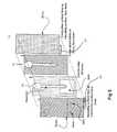
- FIG. 1shows an exploded view of a device in accordance with the invention.
- FIGS. 2A and Bshow a cross-sectional view through a device in accordance with the invention.
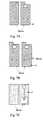
- FIG. 3shows the dimensions of the various cuts in one embodiment of layer 2 as depicted in FIG. 1 .
- FIG. 4shows a further embodiment of a device in accordance with the invention.
- FIG. 5shows a further embodiment of a device in accordance with the invention.
- FIG. 6shows a die cuts layers used in making a device according to the invention.
- FIGS. 7A-Fshow construction steps in making one embodiment of the device of the invention.
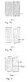
- FIGS. 8A and Bshow the parts of one embodiment of the invention manufactured as a multi-device sheet.
- FIGS. 10A and Bshow circuits that can be used to evaluate the current between the electrodes.
- FIG. 11shows two current profiles, one in which blood coagulates and the other in which is does not.
- FIG. 12schematically depicts the determination of plateau current time by extrapolation.
- FIG. 13shows current profiles for a device in accordance with the invention using two different wetting agents.
- FIG. 14shows the results from a series of experiments in which coagulation times were observed when venous blood was exposed to different amounts of thromboplastin.
- the present inventionrelates to device for measuring the time it takes for coagulation or other loss of flow capability to occur in a blood or other liquid sample.
- the measured quantityis prothrombin time of blood.
- the present applicationuses the term “coagulation time” to refer to the time to takes for blood or other liquid sample flow through the device of the invention to stop, regardless of the specific nature of the interaction that leads to this result.
- FIGS. 1 and 2A and BOne embodiment of the device of the invention is shown in FIGS. 1 and 2A and B.
- the stripis formed as a sandwich of facing electrodes (e.g., gold, carbon, platinum, palladium, etc.) and adhesive layers.
- Layer 1is gold on one side and polyester (insulating) on the other side.
- the insulating polyester layeris exposed on the outer surface of the strip (face up in this diagram) and the conductive gold surface faces the interior of the strip.
- Layer 2is an insulating layer with double-sided adhesive coatings.
- Layer 3is an insulating layer with adhesive on one side facing layer 4 .
- Layer 4is gold on the side facing layer 3 and polyester (insulating) on the other side.
- Cutsare formed in layers 2 and 3 to define sample entry openings and reservoir openings.
- the cut in layer 2also defines a sink opening. Therefore, the thickness of the reservoir is greater than the drain, for example twice as great if layers 2 and 3 have the same thickness.
- the relative thickness of the reservoir and of the sinkare such that the blood flows readily into the sink by wetting action.
- a wetting agentsuch as Triton X-100TM, a non-ionic octylphenol ethoxylate surfactant of the formula alpha-[4-(1,1,3,3-tetramethylbutyl)phenyl]-omega-hydroxypoly(oxy-1,2-ethanediyl) or Surfactant 10-GTM, which is p-nonyl phenoxypolyglycidol
- Triton X-100TMa non-ionic octylphenol ethoxylate surfactant of the formula alpha-[4-(1,1,3,3-tetramethylbutyl)phenyl]-omega-hydroxypoly(oxy-1,2-ethanediyl) or Surfactant 10-GTM, which is p-nonyl phenoxypolyglycidol
- wetting forcesare influenced by many factors, including but not limited to channel dimensions, surface textures, contact angles, surface tensions, and the presence of wetting agents or wicking agents.
- the test stripis suitably designed to cause the wetting forces in the sink to be greater than those in the reservoir such that blood flows readily into the sink by wetting action.
- the reservoirmay contain a surfactant as well. If this is the case, the surfactant in the sink is suitably a more effective wetting agent than the one in the reservoir, although the same surfactant may be used in both chambers, particularly if other construction factors cause a difference in the wetting action of the two chambers.
- the electrodesare disposed on the inner walls of the reservoir and the electrode area is defined by the openings in layers 2 and 3 .
- Score lines 22 in layers 1 , 2 and 4can be used to define the length of the electrode surface 21 .
- the electrodesmay extend for the entire length of the reservoir, or may extend for only a portion of the reservoir length.
- the score 22 in the electrode surface of layer 1ensures that no part of the active electrode is located in the sink. As a result, no current flows due to that portion of the sample which has left the reservoir.
- the layers 1 and 4may be the same length ( FIG. 2A ) or of different lengths ( FIG. 2B ).
- the opening for delivering the sample into the reservoirwill suitably facilitate the entry of air into the reservoir following the draining of the sample.
- the opening of the reservoirmay be shaped or placed in contact with certain materials such that the trailing meniscus of the sample might readily enter the reservoir.
- Hole Aprovides an opening for electrical contact to layer 1 .
- Holes B and Care air vents to allow for displacement of the air in the sink by sample from the reservoir.
- FIG. 3shows the dimensions of the various cuts in one embodiment of layer 2 as depicted in FIG. 1 .
- the specific dimensions as shownare not critical, however, and may be varied.
- the size and shape of the constriction 31 between the reservoir 32 and the sink 33may be varied to affect the rate of flow of the sample from the reservoir to the sink.
- the overall size of each componentmay be changed, consistent with the overall size of the device and the intended sample volume, provided that the length and volume of the reservoir is such that meaningful current measurements can be made that distinguish between flowing and coagulated blood.
- the relative sizes of the reservoir, the sink, and a region at the connection of the reservoir and the sinkare such that the time required for emptying sample from the reservoir to occur in the absence of coagulation is greater than the time required for coagulation to occur.
- the time required for emptyingmay suitably be at least 1.5 times the amount of time required for coagulation to occur in a slow-coagulating sample.
- FIG. 4shows a further embodiment of a device in accordance with the invention.
- layer 1extends for only a portion of the length of the device and hole A is used to provide access to the electrode for an electrical connection.
- layer 41has a sample entry opening 45 and a connection tab 42 and layer 44 has a symmetrical connector tab 43 .
- the internal structureis substantially the same.
- FIG. 5shows a further embodiment of the device of the invention having layer 51 and layer 54 .
- the sample entry opening 52is through the end of the device, and the connector tabs 53 and 53 ′ extend downwards at the end opposite the sample entry opening. Modification of the score lines provides connectivity to the connector tabs 53 , 53 ′ while still electrically isolating the sink.
- the device of the inventiongenerally includes:
- the devicemay optionally include one or more of the following:
- Metal compounds and complexes(especially, but not limited to, Ru, Os, Fe, and Co) containing ligands of the following types: bipyridyl, phenanthroline, imidazole, thiolene/thiolate/thioether/sulfide, porphyrins, pyrrole/pyrrazole/thiazole/diazole/triazole, carboxylate, oxo, quinone, hydrates/hydroxo, aminates, acetates, thiolates, halides, thiocyanates, cyanides, aminoacetates, for example EDTA (Ethylenediaminetetraacetic acid), especially Fe(III)-EDTA, NTA (Nitrilotriacetic acid), ADA (beta-alaninediacetic acid), MGDA (methyleneglycine diacetic acid), IDS (iminodisuccinate), GLUDA (glutamate N,N′-bisdiacetic
- Metal clustersi.e. more than one metal in the compound
- a device of the type depicted in FIGS. 2A and Bcan be prepared by preparing adhesive layers 2 and 3 by die cutting to form the sample openings and the sink as shown in FIG. 6 . These layers are laminated together, and then a further cut is made to form the reservoir. The resulting structure is attached to the gold sides of the polyester substrate layer 4 (see FIGS. 2A or B above). Excess adhesive and gold layers that may be present, and that may have been used for alignment during die cutting is removed, and hole A is punched. If desired, thromboplastin (sold under the trade name Innovin®) is applied to the reservoir and CMC Triton® X-100 is applied to the sink.
- Innovin®thromboplastin
- layer 1is applied and excess gold that may be present at the bottom of layer 1 and have been used for alignment during die cutting is removed and holes B and C are punched. If multiple strips were made as a unit, they can be cut apart before or after punching of holes B and C, and this cutting may also accomplish any necessary trimming or extra materials.
- a device of the type depicted in FIG. 4can be prepared using the steps outlined in FIGS. 7A-F .
- layer 41is produced from a sheet of conductive material that is insulated on one surface. A single die may be used to produce all features of this layer, except for the score on the conductive surface.
- the layeris then scored in the desired pattern, in this case a transverse line ( FIG. 7B ).
- the scoring of the conductive surfacescan be accomplished by laser etching, mechanical scoring using a blade, or any other technique that results in a break in the conductive coating but not the underlying insulation.
- Layer 2is an insulating spacer layer, and is suitably a double-sided adhesive layer. It will be appreciated, however, that separate adhesive layers or subsequently applied adhesive can be employed or that the layers might be joined by heat sealing in all embodiments of the invention where adhesive layers are described. All features of this layer may be produced by a single die cut as shown in FIG. 7C .
- Layer 3is a an insulating spacer layer, and is suitably a single-sided adhesive layer. All features of this layer may be produced by a single die cut as shown in FIG. 7D .
- Layer 44is produced from a sheet of conductive material that is insulated on one surface. A single die may be used to produce all features of this layer, except for the score on the conductive surface ( FIG. 7E ). The score, if desired, in then formed ( FIG. 7F ).
- the layers made in accordance with FIGS. 7A-Fare laminated together to complete the assembly of the device. Layer lamination, application of reagent(s) to the test strip, and drying of the strip once reagent has been applied may occur at different steps along the fabrication process.
- the devices of the inventioncan be made by forming multiple devices on a single series of die-cut sheets, and then cutting the resulting composite apart to provide individual devices.
- FIG. 8Ashows such a composite sheet 801 that can be cut apart to form five devices 802 along cut lines 803 and 804 , and vertical cut lines 805 and 806 .
- FIG. 8Bshows the layers that are used to make up the composite sheet 801 .
- Layer 810has the electrode material, for example gold on the upper surface as shown, and a substrate material such as polyester on the other surface.
- Layer 811is a spacer/insulating layer and is adhered to the electrode side of layer 810 .
- Layer 812is a second spacer/insulating layer that is disposed over layer 811 .
- Layer 813has electrode material disposed on the side facing layer 812 , and a substrate such as polyester on the outside.
- each devicehas a reservoir 820 and a sink 821 separated by a constriction 822 .
- the sink 821is vented at the bottom 823 through a hole that results when the device is separated from the composite sheet 801 along cut line 804 .
- Larger holes 824 at the end of the sinkfacilitate the foimation of this vent hole.
- the sample addition opening 825is formed the top end of the device when it is cut from the composite sheet 801 along cut line 803 .
- Registration holes 895can be positioned at the sample addition ends of at least some of devices to assist in the formation of the sample addition hole.
- some or all of the devicescan be formed with a supplemental opening 826 adjacent to the sample addition opening on at least layers 810 and 813 . Opening 826 has a shape that aids in the entry of air to the device after the sample has entered.
- Holes 830 in sheet 810are in alignment with alternating holes 831 in sheets 811 and 812 , while holes 833 are in alignment with the other set of alternating holes 834 in sheets 811 and 812 .
- electrode contacts 827 and 828are formed on facing sides of the device 802 .
- the device of the inventionis used in a combination comprising a test device and an apparatus or meter.
- the apparatusis connected to the first and second electrodes for measuring current flow between the first and second electrodes.
- the apparatuscomprises connectors configured to connect to the first and second contact leads, a signal processor for converting a current signal to an indication of coagulation time, and means for communicating the indication of coagulation time to a user.
- FIG. 9shows an exterior view of a combination in accordance with the invention.
- the apparatushas a housing 81 with a slot 82 into which device 83 is received.
- Display 84provides means for communicating a qualitative or quantitative result to a user. Examples of suitable displays include LED and LCD displays. Communications may also occur through wired or wireless transmission of results to a separate device. Buttons, such as button 85 may be supplied for turning the apparatus on and off.
- the meteralso comprises a processor with appropriate instructions sets and storage capability to determine the coagulation time and communicate it to a user.
- FIGS. 10A and Bshows a circuit that can be used to evaluate the current between the electrodes and hence the coagulation time of the sample.
- FIG. 10Ashows an arrangement where the counter electrode and the reference electrode can be combined into one single electrode.
- FIG. 10Bis an improvement over the previous design; the inclusion of a voltmeter that can measure the potential across the electrodes.
- the potential applied between the electrodesmay be a steady state potential difference or it may be an AC potential.
- a wide range of frequenciesmay be used.
- the frequency modulation in an applied AC potentialmay take the shape of a sine-wave but other potential shapes, including sawtooth shapes may also be used.
- the userplaces a test device in a test meter, and applies a small sample of blood (for example about 15 microliters) to the sample entry port on the test device.
- Application of bloodcan be detected based on resistance between the electrodes, or a manual start signal can be given, for example using button 85 in FIG. 9 .
- Currentis measured across the reservoir and between the electrodes.
- FIG. 11shows two current profiles, one in which blood coagulates and the other in which is does not.
- the two samplesboth contain Innovin, which promotes coagulation.
- EDTAis also added. EDTA sequesters Ca 2+ and prevents coagulation even in the presence of Innovin®.
- Rate of decaycan be determined by frequency analysis, the initial slope or curve fitting and extrapolating to a time of zero, or predetermined low current.
- the predetermined low currentmay, for example, be set of an average value of plateau current which is discussed further below.
- An assessment of coagulation timecan also be made by determining the time at which the phase transition from flowing to coagulated occurs, as reflected by the sudden “elbow” in the current profile. This can be detected by changes in the slope.
- the current profilecan be seen to have two parts: a declining portion with a slope of ⁇ 0.15 mA/s, and a plateau portion with a slope of ⁇ 0.01 mA/s.
- the intermediate numerical value which characterizes the transition from one slope to the other with a suitable degree of reliabilitycan be determined empirically. It may also be determined as the point at which the second derivative of the slope is at a maximum.
- coagulation timeis determined from a combination of initial slope and the plateau current as illustrated in FIG. 12 .
- Determination of plateau currentmay be made when the slope of the current is within a certain limit of zero.
- a Cottrell current analysismay be used to determine if the current has reached the plateau current.
- Fourier analysismay also be used to determine if the current has reached the plateau current.
- the time at which the extrapolated initial decay passes through the value of the plateau currentis taken as the value of coagulation time PT.
- Coagulation timemay also be determined on the basis of the value of the measured current. For example, from FIG. 11 , the measured current at 60 seconds in the solid line corresponds to a certain coagulation time. Similarly, current measured at 60 seconds for an array of decay profiles (not shown in FIG. 11 ) will correspond to different coagulation times. Therefore, for any given apparatus and known manufacturing tolerances one can establish a calibration constant or curve that relates the measured amount of current at a time when the plateau has consistently been achieved with the coagulation time.
- FIG. 13shows current profiles for a device in accordance with the invention using two different wetting agents. As shown, the change in current is more pronounced when Surfactant 10-GTM is used (solid line) than when Triton X-100TM is used.
- FIG. 14shows the results from a series of experiments in which coagulation times were observed when venous blood was exposed to different amounts of thromboplastin to result in different coagulation times. As shown, the expected linear relationship was observed between the measured coagulation time and the amount of thromboplastin with less thromboplastin (higher dilution) resulting in longer coagulation times.
- the device and method of the inventioncan also be used to detect changes in flow characteristics of a liquid sample that are the result of protein-protein interaction, antibody-antigen, antibody-hapten or other specific binding interactions.
- the following examplesare provided to further elucidate such uses but are not intended to be limiting on the scope of the invention.
- the device of the inventionis used for pathogen identification/classification to distinguish Staphylococcus aureus from other members of the genus such as S. hyicus .
- This application of the inventionis based on the presence of clumping factor on cells S. aureus but not on cells of other members of the genus.
- Clumping factorbinds to fibrinogen or fibrin present in human blood or rabbit plasma resulting in agglutination of cells and thus in a change of flow characteristics.
- a sample containing S. aureuscan be distinguished from a staph sample of another species by introduction into of the sample into a device of the invention where the device contains fibrinogen or fibrin.
- the fibrinogen or fibrinmay be present in the device prior to introduction of the sample, for example coated on the walls of the device, or may be added with the sample. Additional S. aureus specific binding materials, such as anti-protein A immunoglobulin G may be used in addition or in the alternative to fibrin or fibrinogen.
- blood typecan be determined using standard antibodies to A, B and Rh antigens and the addition of a whole blood sample.
- the antibodies specific to A, B and Rh antigensare well known, and are routinely used in blood testing. Rapid testing, however, may require the visual observation and subjective determination of agglutination as an indication of a positive test. Placing the antibody in the device of the present invention, either before or with the sample results in a numerical result rather than a subjective assessment, and therefore provide a more consistent yet still rapid determination of blood type.
- tests for hemagglutinin found on the surface of influenza and other virusare commonly performed in a V-bottom microtiter plate using dilutions of attenuated viral particles and a constant concentration of red blood cells.
- the dilutionsare used to determine the amount of virus present, but are cumbersome and require a trained technician.
- Adherence of the red blood cellsis observed as an indication of the presence and activity of viral hemagglutinin by tilting the wells and looking for the absence of flow. This test is not only subjective, but for the most parts the titer of viral particles in biological fluids is insufficient to make this test of diagnostic relevance.
- Hemagglutination reactions to detect antibodiesare also known based on antigen-coated reagent erythrocytes. In either case, change in flow characteristics of the type monitored in the present invention are used.
- the present inventioncan be used to detect viral hemagglutinin or on other hemagglutination reactions by introducing the sample fluid with red blood cells (native or antigen coated) or antigen-coated particles that mimic the red blood cells and observed changes in flow characteristics. Because a reduction in flow can observed as well as complete cessation, dilutions to obtain an estimate of viral titer are not required.
- the surfaces of the substrates and the electrodesare shown in a generally planar configuration.
- the inventionis not limited to such a configuration, however.
- the substrate and/or the electrodemay have a sawtooth or undulating surface which can increase the length of the sample space/reservoir without having to increase the overall length of the device.
- the tubeis depicted as generally linear, a tube in the shape of a J, inverted-J or U or other bent shapes can be used to increase the length available for sample flow as well.
- the devices of the inventionare also depicted utilizing passive flow, based either on gravitational flow or capillarity due to the spacing between the walls.
- the device of the inventionmay also make use of assisted flow, for example using pressure or suction.
Landscapes
- Health & Medical Sciences (AREA)
- Life Sciences & Earth Sciences (AREA)
- Engineering & Computer Science (AREA)
- Chemical & Material Sciences (AREA)
- Biomedical Technology (AREA)
- Hematology (AREA)
- Physics & Mathematics (AREA)
- Immunology (AREA)
- Molecular Biology (AREA)
- Urology & Nephrology (AREA)
- Pathology (AREA)
- Analytical Chemistry (AREA)
- Biochemistry (AREA)
- General Health & Medical Sciences (AREA)
- General Physics & Mathematics (AREA)
- Food Science & Technology (AREA)
- Medicinal Chemistry (AREA)
- Biophysics (AREA)
- Ecology (AREA)
- Biotechnology (AREA)
- Cell Biology (AREA)
- Microbiology (AREA)
- Chemical Kinetics & Catalysis (AREA)
- Electrochemistry (AREA)
- Investigating Or Analysing Biological Materials (AREA)
- Investigating Or Analyzing Materials By The Use Of Electric Means (AREA)
Abstract
Description
- Means for connecting the strip to a meter. Examples of such means include openings through the layers by which connection can be made to the electrode surfaces, or connector tabs extending beyond the interior insulating layers. The connector tabs can be located at either end, or on the sides of the device.
- At least two electrodes in contact with the inner volume of a reservoir. The electrodes can be made from any suitable conductive material, including without limitation gold, silver, platinum, palladium, and conductive carbon. Mesh electrodes may be formed from any of these materials to increase the surface area of the electrode. In one specific embodiment, the electrodes are made from a conductive carbon mesh.
- At least one opening for delivering the sample into the reservoir.
- At least one opening to allow for draining of the sample from the reservoir.
- At least one sink for collecting draining sample from the reservoir.
- At least one air vent to allow for displacement of air in the sink by sample that collects in the sink.
- a reagent to promote blood coagulation that is indicative the clotting ability of the blood, which is applied during strip construction. Examples of suitable reagents include thromboplastin, reptilase, metals, such as silver (I) or mercury (II), and biopolymers such as collagen, thrombin, prothrombin, fibrin, fibrinogen, heparinase, Factor VIIa, Factor VIII, Factor IXa, Factor Xa, Factor XII, von Willebrand Factor, a selectin, a procoagulant venom, a plasminogen activator inhibitor, glycoprotein IIb-IIIa, a protease, or plasma. This reagent is considered optional because it can be combined with the sample prior to introduction to the device, although this may not generally be preferred since it adds additional steps to the process. Further, in devices using a second reagent as described below, this agent may be unnecessary.
- a second reagent to promote a change in flow characteristics of the blood if a target analyte material is present in the blood sample. Second reagents are suitably those that will undergo protein-protein or antibody-antigen interactions with analytes of interest that may be present in the blood. Examples of second reagents include antibodies used in blood typing, antigens to detect the presence of antibodies of interest in the blood (for example antibodies specific to disease causing organisms, and autoantibodies as in an ANA test), and antibodies to detect antigens of interest in the blood (for example prostate specific antigen (PSA) and other diagnostic cancer antigens. Stated generally, in one embodiment, the second reagent and the target analyte material are members of an antibody/antigen pair.
- a reagent for modifying the surface properties of the sample (e.g., Triton X-100™ or Surfactant 10-G™), which is applied during strip construction.
- a constriction between the reservoir and the sink. The constriction controls the flow rate from the reservoir so that coagulation will occur prior to complete drainage from the reservoir. The constriction is unnecessary when the dimensions of the reservoir itself are such that this characteristic is obtained.
- an electron transfer agent to shuttle electrons from the electron source (e.g. the negative electrode) to the electron sink (e.g. the positive electrode). Examples of suitable electron transfer agents include, without limitation:
- a score in at least one of the electrode surfaces to ensure that no current flows when the sample enters a certain region of the strip, particularly the sink.
Claims (25)
Priority Applications (10)
| Application Number | Priority Date | Filing Date | Title |
|---|---|---|---|
| US11/279,044US7837941B2 (en) | 2006-04-07 | 2006-04-07 | Method and apparatus for monitoring alteration of flow characteristics in a liquid sample |
| EP07735322.5AEP2005159B1 (en) | 2006-04-07 | 2007-03-29 | Method and apparatus for monitoring alteration of flow characteristics in a liquid sample |
| CNA2007800212107ACN101484805A (en) | 2006-04-07 | 2007-03-29 | Method and apparatus for monitoring alteration of flow characteristics in a liquid sample |
| PCT/IB2007/051129WO2007116336A2 (en) | 2006-04-07 | 2007-03-29 | Method and apparatus for monitoring alteration of flow characteristics in a liquid sample |
| CA2648233ACA2648233C (en) | 2006-04-07 | 2007-03-29 | Method and apparatus for monitoring alteration of flow characteristics in a liquid sample |
| EP13189289.5AEP2698630B1 (en) | 2006-04-07 | 2007-03-29 | Method and apparatus for monitoring alteration of flow characteristics in a liquid sample |
| AU2007237147AAU2007237147B2 (en) | 2006-04-07 | 2007-03-29 | Method and apparatus for monitoring alteration of flow characteristics in a liquid sample |
| KR1020087024545AKR20080109016A (en) | 2006-04-07 | 2007-03-29 | Methods and apparatus for monitoring changes in flow characteristics of liquid samples |
| US12/947,268US8623280B2 (en) | 2006-04-07 | 2010-11-16 | Method and apparatus for monitoring alteration of flow characteristics in a liquid sample |
| US14/092,228US8999242B2 (en) | 2006-04-07 | 2013-11-27 | Method and apparatus for monitoring alteration of flow characteristics in a liquid sample |
Applications Claiming Priority (1)
| Application Number | Priority Date | Filing Date | Title |
|---|---|---|---|
| US11/279,044US7837941B2 (en) | 2006-04-07 | 2006-04-07 | Method and apparatus for monitoring alteration of flow characteristics in a liquid sample |
Related Child Applications (1)
| Application Number | Title | Priority Date | Filing Date |
|---|---|---|---|
| US12/947,268ContinuationUS8623280B2 (en) | 2006-04-07 | 2010-11-16 | Method and apparatus for monitoring alteration of flow characteristics in a liquid sample |
Publications (2)
| Publication Number | Publication Date |
|---|---|
| US20070235329A1 US20070235329A1 (en) | 2007-10-11 |
| US7837941B2true US7837941B2 (en) | 2010-11-23 |
Family
ID=38574003
Family Applications (3)
| Application Number | Title | Priority Date | Filing Date |
|---|---|---|---|
| US11/279,044Active2029-07-30US7837941B2 (en) | 2006-04-07 | 2006-04-07 | Method and apparatus for monitoring alteration of flow characteristics in a liquid sample |
| US12/947,268Active2027-11-08US8623280B2 (en) | 2006-04-07 | 2010-11-16 | Method and apparatus for monitoring alteration of flow characteristics in a liquid sample |
| US14/092,228ActiveUS8999242B2 (en) | 2006-04-07 | 2013-11-27 | Method and apparatus for monitoring alteration of flow characteristics in a liquid sample |
Family Applications After (2)
| Application Number | Title | Priority Date | Filing Date |
|---|---|---|---|
| US12/947,268Active2027-11-08US8623280B2 (en) | 2006-04-07 | 2010-11-16 | Method and apparatus for monitoring alteration of flow characteristics in a liquid sample |
| US14/092,228ActiveUS8999242B2 (en) | 2006-04-07 | 2013-11-27 | Method and apparatus for monitoring alteration of flow characteristics in a liquid sample |
Country Status (7)
| Country | Link |
|---|---|
| US (3) | US7837941B2 (en) |
| EP (2) | EP2005159B1 (en) |
| KR (1) | KR20080109016A (en) |
| CN (1) | CN101484805A (en) |
| AU (1) | AU2007237147B2 (en) |
| CA (1) | CA2648233C (en) |
| WO (1) | WO2007116336A2 (en) |
Cited By (5)
| Publication number | Priority date | Publication date | Assignee | Title |
|---|---|---|---|---|
| US20110083974A1 (en)* | 2006-04-07 | 2011-04-14 | Agamatrix, Inc. | Method and apparatus for monitoring alteration of flow characteristics in a liquid sample |
| US20130009894A1 (en)* | 2011-07-07 | 2013-01-10 | Wintek Corporation | Touch-sensitive display panel |
| US10414953B2 (en) | 2016-02-19 | 2019-09-17 | Avery Dennison Corporation | Two stage methods for processing adhesives and related compositions |
| US10640595B2 (en) | 2016-10-25 | 2020-05-05 | Avery Dennison Corporation | Controlled architecture polymerization with photoinitiator groups in backbone |
| US12163069B2 (en) | 2017-12-19 | 2024-12-10 | Avery Dennison Corporation | Post-polymerization functionalization of pendant functional groups |
Families Citing this family (63)
| Publication number | Priority date | Publication date | Assignee | Title |
|---|---|---|---|---|
| US6391005B1 (en) | 1998-03-30 | 2002-05-21 | Agilent Technologies, Inc. | Apparatus and method for penetration with shaft having a sensor for sensing penetration depth |
| US8641644B2 (en) | 2000-11-21 | 2014-02-04 | Sanofi-Aventis Deutschland Gmbh | Blood testing apparatus having a rotatable cartridge with multiple lancing elements and testing means |
| US9427532B2 (en) | 2001-06-12 | 2016-08-30 | Sanofi-Aventis Deutschland Gmbh | Tissue penetration device |
| US7981056B2 (en) | 2002-04-19 | 2011-07-19 | Pelikan Technologies, Inc. | Methods and apparatus for lancet actuation |
| US9226699B2 (en) | 2002-04-19 | 2016-01-05 | Sanofi-Aventis Deutschland Gmbh | Body fluid sampling module with a continuous compression tissue interface surface |
| US7344507B2 (en) | 2002-04-19 | 2008-03-18 | Pelikan Technologies, Inc. | Method and apparatus for lancet actuation |
| US8337419B2 (en) | 2002-04-19 | 2012-12-25 | Sanofi-Aventis Deutschland Gmbh | Tissue penetration device |
| US9795747B2 (en) | 2010-06-02 | 2017-10-24 | Sanofi-Aventis Deutschland Gmbh | Methods and apparatus for lancet actuation |
| US7041068B2 (en) | 2001-06-12 | 2006-05-09 | Pelikan Technologies, Inc. | Sampling module device and method |
| EP1395185B1 (en) | 2001-06-12 | 2010-10-27 | Pelikan Technologies Inc. | Electric lancet actuator |
| JP4209767B2 (en) | 2001-06-12 | 2009-01-14 | ペリカン テクノロジーズ インコーポレイテッド | Self-optimized cutting instrument with adaptive means for temporary changes in skin properties |
| US7749174B2 (en) | 2001-06-12 | 2010-07-06 | Pelikan Technologies, Inc. | Method and apparatus for lancet launching device intergrated onto a blood-sampling cartridge |
| US7232451B2 (en) | 2002-04-19 | 2007-06-19 | Pelikan Technologies, Inc. | Method and apparatus for penetrating tissue |
| US7901362B2 (en) | 2002-04-19 | 2011-03-08 | Pelikan Technologies, Inc. | Method and apparatus for penetrating tissue |
| US8267870B2 (en) | 2002-04-19 | 2012-09-18 | Sanofi-Aventis Deutschland Gmbh | Method and apparatus for body fluid sampling with hybrid actuation |
| US9795334B2 (en) | 2002-04-19 | 2017-10-24 | Sanofi-Aventis Deutschland Gmbh | Method and apparatus for penetrating tissue |
| US7976476B2 (en) | 2002-04-19 | 2011-07-12 | Pelikan Technologies, Inc. | Device and method for variable speed lancet |
| US7229458B2 (en) | 2002-04-19 | 2007-06-12 | Pelikan Technologies, Inc. | Method and apparatus for penetrating tissue |
| US8360992B2 (en) | 2002-04-19 | 2013-01-29 | Sanofi-Aventis Deutschland Gmbh | Method and apparatus for penetrating tissue |
| US8221334B2 (en) | 2002-04-19 | 2012-07-17 | Sanofi-Aventis Deutschland Gmbh | Method and apparatus for penetrating tissue |
| US7892183B2 (en) | 2002-04-19 | 2011-02-22 | Pelikan Technologies, Inc. | Method and apparatus for body fluid sampling and analyte sensing |
| US7491178B2 (en) | 2002-04-19 | 2009-02-17 | Pelikan Technologies, Inc. | Method and apparatus for penetrating tissue |
| US7297122B2 (en) | 2002-04-19 | 2007-11-20 | Pelikan Technologies, Inc. | Method and apparatus for penetrating tissue |
| US9248267B2 (en) | 2002-04-19 | 2016-02-02 | Sanofi-Aventis Deustchland Gmbh | Tissue penetration device |
| US7674232B2 (en) | 2002-04-19 | 2010-03-09 | Pelikan Technologies, Inc. | Method and apparatus for penetrating tissue |
| US8784335B2 (en) | 2002-04-19 | 2014-07-22 | Sanofi-Aventis Deutschland Gmbh | Body fluid sampling device with a capacitive sensor |
| US7331931B2 (en) | 2002-04-19 | 2008-02-19 | Pelikan Technologies, Inc. | Method and apparatus for penetrating tissue |
| US7547287B2 (en) | 2002-04-19 | 2009-06-16 | Pelikan Technologies, Inc. | Method and apparatus for penetrating tissue |
| US7708701B2 (en) | 2002-04-19 | 2010-05-04 | Pelikan Technologies, Inc. | Method and apparatus for a multi-use body fluid sampling device |
| US7909778B2 (en) | 2002-04-19 | 2011-03-22 | Pelikan Technologies, Inc. | Method and apparatus for penetrating tissue |
| US8702624B2 (en) | 2006-09-29 | 2014-04-22 | Sanofi-Aventis Deutschland Gmbh | Analyte measurement device with a single shot actuator |
| US8372016B2 (en) | 2002-04-19 | 2013-02-12 | Sanofi-Aventis Deutschland Gmbh | Method and apparatus for body fluid sampling and analyte sensing |
| US9314194B2 (en) | 2002-04-19 | 2016-04-19 | Sanofi-Aventis Deutschland Gmbh | Tissue penetration device |
| US8579831B2 (en) | 2002-04-19 | 2013-11-12 | Sanofi-Aventis Deutschland Gmbh | Method and apparatus for penetrating tissue |
| US8574895B2 (en) | 2002-12-30 | 2013-11-05 | Sanofi-Aventis Deutschland Gmbh | Method and apparatus using optical techniques to measure analyte levels |
| DE602004028463D1 (en) | 2003-05-30 | 2010-09-16 | Pelikan Technologies Inc | METHOD AND DEVICE FOR INJECTING LIQUID |
| US7850621B2 (en) | 2003-06-06 | 2010-12-14 | Pelikan Technologies, Inc. | Method and apparatus for body fluid sampling and analyte sensing |
| WO2006001797A1 (en) | 2004-06-14 | 2006-01-05 | Pelikan Technologies, Inc. | Low pain penetrating |
| US8282576B2 (en) | 2003-09-29 | 2012-10-09 | Sanofi-Aventis Deutschland Gmbh | Method and apparatus for an improved sample capture device |
| EP1680014A4 (en) | 2003-10-14 | 2009-01-21 | Pelikan Technologies Inc | METHOD AND DEVICE FOR A VARIABLE USER INTERFACE |
| US7822454B1 (en) | 2005-01-03 | 2010-10-26 | Pelikan Technologies, Inc. | Fluid sampling device with improved analyte detecting member configuration |
| US8668656B2 (en) | 2003-12-31 | 2014-03-11 | Sanofi-Aventis Deutschland Gmbh | Method and apparatus for improving fluidic flow and sample capture |
| WO2006011062A2 (en) | 2004-05-20 | 2006-02-02 | Albatros Technologies Gmbh & Co. Kg | Printable hydrogel for biosensors |
| US9775553B2 (en) | 2004-06-03 | 2017-10-03 | Sanofi-Aventis Deutschland Gmbh | Method and apparatus for a fluid sampling device |
| WO2005120365A1 (en) | 2004-06-03 | 2005-12-22 | Pelikan Technologies, Inc. | Method and apparatus for a fluid sampling device |
| US8652831B2 (en) | 2004-12-30 | 2014-02-18 | Sanofi-Aventis Deutschland Gmbh | Method and apparatus for analyte measurement test time |
| TWI516601B (en)* | 2007-10-26 | 2016-01-11 | 環球生物醫療感測器私人有限公司 | Apparatus and method for electrochemical detection |
| EP2265324B1 (en) | 2008-04-11 | 2015-01-28 | Sanofi-Aventis Deutschland GmbH | Integrated analyte measurement system |
| EP2144061A1 (en)* | 2008-07-11 | 2010-01-13 | F. Hoffmann-Roche AG | Continuous method for inline application of tensides on coated sensor film |
| US9375169B2 (en) | 2009-01-30 | 2016-06-28 | Sanofi-Aventis Deutschland Gmbh | Cam drive for managing disposable penetrating member actions with a single motor and motor and control system |
| US8965476B2 (en) | 2010-04-16 | 2015-02-24 | Sanofi-Aventis Deutschland Gmbh | Tissue penetration device |
| US9551699B2 (en)* | 2012-07-16 | 2017-01-24 | Micropoint Bioscience, Inc. | Testing of blood coagulation characteristics |
| RU2598162C1 (en)* | 2012-09-07 | 2016-09-20 | Цилаг Гмбх Интернэшнл | Electrochemical sensors and method for production thereof |
| CN105214744A (en)* | 2015-10-26 | 2016-01-06 | 深圳华迈兴微医疗科技有限公司 | A kind of magnetic microparticle chemiluminescence micro-fluidic chip |
| CN105628747B (en)* | 2015-12-18 | 2019-03-22 | 上海奥普生物医药有限公司 | Clotting time device for testing and analyzing and its method for testing and analyzing |
| TWI572330B (en)* | 2015-12-28 | 2017-03-01 | 國立中興大學 | Device for blood typing |
| US10633645B2 (en)* | 2015-12-30 | 2020-04-28 | General Electric Company | Calcium controlled activation of platelets via electrical stimulation |
| WO2017123266A1 (en)* | 2016-01-16 | 2017-07-20 | Hewlett-Packard Development Company, L.P. | Blood characteristic measurement |
| JP6547230B2 (en) | 2016-04-03 | 2019-07-24 | ウラカミ合同会社 | Negative pressure adsorption self-propelled robotic device |
| CN108761105B (en)* | 2018-06-01 | 2020-12-01 | 广州万孚生物技术股份有限公司 | Blood coagulation time determination method, electronic device, and storage medium |
| US10915444B2 (en)* | 2018-12-27 | 2021-02-09 | Micron Technology, Inc. | Garbage collection candidate selection using block overwrite rate |
| CN110057890B (en)* | 2019-03-26 | 2021-07-30 | 中国科学院苏州生物医学工程技术研究所 | A blood coagulation detection chip and electrochemical sensor |
| CN111735970B (en)* | 2020-07-23 | 2020-12-01 | 南京岚煜生物科技有限公司 | Method for carrying out coagulation analysis by coagulation analysis system |
Citations (23)
| Publication number | Priority date | Publication date | Assignee | Title |
|---|---|---|---|---|
| US3699437A (en) | 1968-09-27 | 1972-10-17 | Amiram Ur | Blood coagulation detection method and apparatus |
| US3967934A (en) | 1969-06-13 | 1976-07-06 | Baxter Laboratories, Inc. | Prothrombin timer |
| US4547735A (en)* | 1982-01-23 | 1985-10-15 | Holger Kiesewetter | Instrument for measuring the hematocrit value of blood |
| US4756884A (en) | 1985-08-05 | 1988-07-12 | Biotrack, Inc. | Capillary flow device |
| US4764465A (en)* | 1984-04-26 | 1988-08-16 | Cetus Corporation | Human monoclonal antibody against group A red blood cells |
| US4829011A (en) | 1987-08-27 | 1989-05-09 | Biotrack, Inc. | Agglutination assay |
| US4849340A (en) | 1987-04-03 | 1989-07-18 | Cardiovascular Diagnostics, Inc. | Reaction system element and method for performing prothrombin time assay |
| US5039617A (en) | 1989-04-20 | 1991-08-13 | Biotrack, Inc. | Capillary flow device and method for measuring activated partial thromboplastin time |
| US5140161A (en) | 1985-08-05 | 1992-08-18 | Biotrack | Capillary flow device |
| US5300779A (en) | 1985-08-05 | 1994-04-05 | Biotrack, Inc. | Capillary flow device |
| US5302348A (en) | 1992-12-10 | 1994-04-12 | Itc Corporation | Blood coagulation time test apparatus and method |
| US5534226A (en) | 1994-10-21 | 1996-07-09 | International Technidyne Corporation | Portable test apparatus and associated method of performing a blood coagulation test |
| US5628961A (en)* | 1993-10-28 | 1997-05-13 | I-Stat Corporation | Apparatus for assaying viscosity changes in fluid samples and method of conducting same |
| US6046051A (en) | 1997-06-27 | 2000-04-04 | Hemosense, Inc. | Method and device for measuring blood coagulation or lysis by viscosity changes |
| US6103196A (en) | 1995-12-27 | 2000-08-15 | Yassinzadeh; Zia | Flow detection apparatus and method |
| US6402704B1 (en) | 2000-04-18 | 2002-06-11 | Sonexxus Incorporated | Prothrombin test apparatus for home use |
| US6451610B1 (en) | 1999-04-14 | 2002-09-17 | International Technidyne Corporation | Method and apparatus for coagulation based assays |
| US6620310B1 (en) | 2000-12-13 | 2003-09-16 | Lifescan, Inc. | Electrochemical coagulation assay and device |
| US20040072357A1 (en) | 2000-12-19 | 2004-04-15 | Matthias Stiene | Device for measuring blood coagulation and method thereof |
| US6750053B1 (en) | 1999-11-15 | 2004-06-15 | I-Stat Corporation | Apparatus and method for assaying coagulation in fluid samples |
| US6759009B2 (en) | 2001-05-04 | 2004-07-06 | Portascience Incorporated | Method and device for clotting time assay |
| US6830934B1 (en)* | 1999-06-15 | 2004-12-14 | Lifescan, Inc. | Microdroplet dispensing for a medical diagnostic device |
| US7021122B1 (en) | 1998-03-19 | 2006-04-04 | Orgenics Biosensors Ltd. | Device for the determination of blood clotting by capacitance or resistance |
Family Cites Families (4)
| Publication number | Priority date | Publication date | Assignee | Title |
|---|---|---|---|---|
| AR038161A1 (en) | 2002-01-24 | 2004-12-29 | Basf Ag | PROCEDURE FOR SEPARATING ACIDS FROM CHEMICAL REACTION MIXTURES WITH THE HELP OF ION LIQUIDS |
| US7291310B2 (en)* | 2002-12-17 | 2007-11-06 | The Regents Of The University Of Michigan | Microsystem for determining clotting time of blood and low-cost, single-use device for use therein |
| US8062901B2 (en) | 2005-04-30 | 2011-11-22 | Alere Switzerland Gmbh | Devices and methods for sample collection and analysis |
| US7837941B2 (en)* | 2006-04-07 | 2010-11-23 | Agamatrix, Inc. | Method and apparatus for monitoring alteration of flow characteristics in a liquid sample |
- 2006
- 2006-04-07USUS11/279,044patent/US7837941B2/enactiveActive
- 2007
- 2007-03-29CACA2648233Apatent/CA2648233C/enactiveActive
- 2007-03-29EPEP07735322.5Apatent/EP2005159B1/enactiveActive
- 2007-03-29EPEP13189289.5Apatent/EP2698630B1/enactiveActive
- 2007-03-29WOPCT/IB2007/051129patent/WO2007116336A2/enactiveApplication Filing
- 2007-03-29KRKR1020087024545Apatent/KR20080109016A/ennot_activeWithdrawn
- 2007-03-29AUAU2007237147Apatent/AU2007237147B2/ennot_activeCeased
- 2007-03-29CNCNA2007800212107Apatent/CN101484805A/enactivePending
- 2010
- 2010-11-16USUS12/947,268patent/US8623280B2/enactiveActive
- 2013
- 2013-11-27USUS14/092,228patent/US8999242B2/enactiveActive
Patent Citations (30)
| Publication number | Priority date | Publication date | Assignee | Title |
|---|---|---|---|---|
| US3699437A (en) | 1968-09-27 | 1972-10-17 | Amiram Ur | Blood coagulation detection method and apparatus |
| US3967934A (en) | 1969-06-13 | 1976-07-06 | Baxter Laboratories, Inc. | Prothrombin timer |
| US4547735A (en)* | 1982-01-23 | 1985-10-15 | Holger Kiesewetter | Instrument for measuring the hematocrit value of blood |
| US4764465A (en)* | 1984-04-26 | 1988-08-16 | Cetus Corporation | Human monoclonal antibody against group A red blood cells |
| US5300779A (en) | 1985-08-05 | 1994-04-05 | Biotrack, Inc. | Capillary flow device |
| US5140161A (en) | 1985-08-05 | 1992-08-18 | Biotrack | Capillary flow device |
| US4756884A (en) | 1985-08-05 | 1988-07-12 | Biotrack, Inc. | Capillary flow device |
| US4849340A (en) | 1987-04-03 | 1989-07-18 | Cardiovascular Diagnostics, Inc. | Reaction system element and method for performing prothrombin time assay |
| US6197494B1 (en) | 1987-04-03 | 2001-03-06 | Cardiovascular Diagnostics, Inc. | Apparatus for performing assays on liquid samples accurately, rapidly and simply |
| US4829011A (en) | 1987-08-27 | 1989-05-09 | Biotrack, Inc. | Agglutination assay |
| US5039617A (en) | 1989-04-20 | 1991-08-13 | Biotrack, Inc. | Capillary flow device and method for measuring activated partial thromboplastin time |
| US5302348A (en) | 1992-12-10 | 1994-04-12 | Itc Corporation | Blood coagulation time test apparatus and method |
| US5372946A (en) | 1992-12-10 | 1994-12-13 | International Technidyne Corporation | Blood coagulation time test apparatus and method |
| US5628961A (en)* | 1993-10-28 | 1997-05-13 | I-Stat Corporation | Apparatus for assaying viscosity changes in fluid samples and method of conducting same |
| US5534226A (en) | 1994-10-21 | 1996-07-09 | International Technidyne Corporation | Portable test apparatus and associated method of performing a blood coagulation test |
| US5591403A (en) | 1994-10-21 | 1997-01-07 | International Technidyne Corporation | Portable prothrombin time test apparatus and associated method of performing a prothrombin time test |
| US6103196A (en) | 1995-12-27 | 2000-08-15 | Yassinzadeh; Zia | Flow detection apparatus and method |
| US6046051A (en) | 1997-06-27 | 2000-04-04 | Hemosense, Inc. | Method and device for measuring blood coagulation or lysis by viscosity changes |
| US6066504A (en) | 1997-06-27 | 2000-05-23 | Hemosense, Inc. | Coagulation or lysis assays using an electroactive species |
| US6338821B1 (en) | 1997-06-27 | 2002-01-15 | Arvind N. Jina | Method and device for measuring blood coagulation or lysis by viscosity changes |
| US6673622B1 (en) | 1997-06-27 | 2004-01-06 | Hemosense, Inc. | Coagulation or lysis assays by measuring impedance |
| US7021122B1 (en) | 1998-03-19 | 2006-04-04 | Orgenics Biosensors Ltd. | Device for the determination of blood clotting by capacitance or resistance |
| US6451610B1 (en) | 1999-04-14 | 2002-09-17 | International Technidyne Corporation | Method and apparatus for coagulation based assays |
| US6830934B1 (en)* | 1999-06-15 | 2004-12-14 | Lifescan, Inc. | Microdroplet dispensing for a medical diagnostic device |
| US6750053B1 (en) | 1999-11-15 | 2004-06-15 | I-Stat Corporation | Apparatus and method for assaying coagulation in fluid samples |
| US6402704B1 (en) | 2000-04-18 | 2002-06-11 | Sonexxus Incorporated | Prothrombin test apparatus for home use |
| US6620310B1 (en) | 2000-12-13 | 2003-09-16 | Lifescan, Inc. | Electrochemical coagulation assay and device |
| US7005857B2 (en) | 2000-12-19 | 2006-02-28 | Lifescan Scotland Limited | Device for measuring blood coagulation and method thereof |
| US20040072357A1 (en) | 2000-12-19 | 2004-04-15 | Matthias Stiene | Device for measuring blood coagulation and method thereof |
| US6759009B2 (en) | 2001-05-04 | 2004-07-06 | Portascience Incorporated | Method and device for clotting time assay |
Non-Patent Citations (1)
| Title |
|---|
| Defintion of term "vent", online version of Webster's Third International Dictionary, Unabridged.* |
Cited By (10)
| Publication number | Priority date | Publication date | Assignee | Title |
|---|---|---|---|---|
| US20110083974A1 (en)* | 2006-04-07 | 2011-04-14 | Agamatrix, Inc. | Method and apparatus for monitoring alteration of flow characteristics in a liquid sample |
| US8623280B2 (en)* | 2006-04-07 | 2014-01-07 | Agamatrix, Inc. | Method and apparatus for monitoring alteration of flow characteristics in a liquid sample |
| US8999242B2 (en) | 2006-04-07 | 2015-04-07 | Agamatrix, Inc. | Method and apparatus for monitoring alteration of flow characteristics in a liquid sample |
| US20130009894A1 (en)* | 2011-07-07 | 2013-01-10 | Wintek Corporation | Touch-sensitive display panel |
| US10414953B2 (en) | 2016-02-19 | 2019-09-17 | Avery Dennison Corporation | Two stage methods for processing adhesives and related compositions |
| US11091675B2 (en) | 2016-02-19 | 2021-08-17 | Avery Dennison Corporation | Two stage methods for processing adhesives and related compositions |
| US11312884B2 (en) | 2016-02-19 | 2022-04-26 | Avery Dennison Corporation | Two stage methods for processing adhesives and related compositions |
| US12065588B2 (en) | 2016-02-19 | 2024-08-20 | Avery Dennison Corporation | Two stage methods for processing adhesives and related compositions |
| US10640595B2 (en) | 2016-10-25 | 2020-05-05 | Avery Dennison Corporation | Controlled architecture polymerization with photoinitiator groups in backbone |
| US12163069B2 (en) | 2017-12-19 | 2024-12-10 | Avery Dennison Corporation | Post-polymerization functionalization of pendant functional groups |
Also Published As
| Publication number | Publication date |
|---|---|
| EP2005159A4 (en) | 2012-09-12 |
| US20110083974A1 (en) | 2011-04-14 |
| EP2698630B1 (en) | 2017-01-18 |
| US8999242B2 (en) | 2015-04-07 |
| US20070235329A1 (en) | 2007-10-11 |
| WO2007116336A3 (en) | 2007-12-21 |
| EP2005159A2 (en) | 2008-12-24 |
| AU2007237147B2 (en) | 2012-04-12 |
| AU2007237147A2 (en) | 2008-11-13 |
| WO2007116336A2 (en) | 2007-10-18 |
| WO2007116336A9 (en) | 2008-11-27 |
| US8623280B2 (en) | 2014-01-07 |
| AU2007237147A1 (en) | 2007-10-18 |
| CN101484805A (en) | 2009-07-15 |
| EP2698630A1 (en) | 2014-02-19 |
| KR20080109016A (en) | 2008-12-16 |
| CA2648233A1 (en) | 2007-10-18 |
| US20140116894A1 (en) | 2014-05-01 |
| EP2005159B1 (en) | 2013-12-25 |
| CA2648233C (en) | 2014-05-06 |
Similar Documents
| Publication | Publication Date | Title |
|---|---|---|
| US8999242B2 (en) | Method and apparatus for monitoring alteration of flow characteristics in a liquid sample | |
| EP1901065B1 (en) | Device and method for measuring properties of a sample | |
| JP3792156B2 (en) | Apparatus and method for analyzing clots in a liquid sample | |
| US6338821B1 (en) | Method and device for measuring blood coagulation or lysis by viscosity changes | |
| EP2395353B1 (en) | Device and method for measuring prothrombin time and hematocrit by analyzing change in reactance in a sample | |
| KR100841355B1 (en) | Biosensor chip with non-powered blood separation means | |
| EP1437589A1 (en) | Strips for analyzing samples | |
| KR20070027607A (en) | Electrochemical cell and electrochemical cell manufacturing method | |
| JP4041779B2 (en) | Inspection device for biological sample liquid analysis | |
| CN114264713A (en) | biological sensor | |
| JP2006308561A (en) | Biosensor | |
| WO2000006761A1 (en) | Method and device for measuring blood coagulation or lysis by viscosity changes | |
| CN209148584U (en) | An Electrochemical Sensor Electrode Test Piece for Multi-parameter Detection | |
| US20230015561A1 (en) | Biosensor for performing detection on biological sample | |
| HK1194472A (en) | Method and apparatus for monitoring alteration of flow characteristics in a liquid sample | |
| HK1194472B (en) | Method and apparatus for monitoring alteration of flow characteristics in a liquid sample | |
| Maji | A Microfluidic Dielectric Sensor for Comprehensive Assessment of Hemostasis | |
| KR20080047265A (en) | Biostrip | |
| TWI589875B (en) | Electrochemical biosensor test strip | |
| CN201075107Y (en) | biochemical sensor | |
| HK1112287B (en) | Device and method for measuring properties of a sample |
Legal Events
| Date | Code | Title | Description |
|---|---|---|---|
| AS | Assignment | Owner name:AGAMATRIX, INC., NEW HAMPSHIRE Free format text:ASSIGNMENT OF ASSIGNORS INTEREST;ASSIGNORS:HARDING, IAN;IYENGAR, SRIDHAR G.;NGUYEN, HA;AND OTHERS;REEL/FRAME:017438/0845 Effective date:20060327 | |
| STCF | Information on status: patent grant | Free format text:PATENTED CASE | |
| FPAY | Fee payment | Year of fee payment:4 | |
| FEPP | Fee payment procedure | Free format text:PAT HOLDER NO LONGER CLAIMS SMALL ENTITY STATUS, ENTITY STATUS SET TO UNDISCOUNTED (ORIGINAL EVENT CODE: STOL); ENTITY STATUS OF PATENT OWNER: LARGE ENTITY | |
| SULP | Surcharge for late payment | ||
| AS | Assignment | Owner name:MIDCAP FINANCIAL TRUST, MARYLAND Free format text:SECURITY INTEREST;ASSIGNOR:AGAMATRIX, INC.;REEL/FRAME:037405/0728 Effective date:20151223 | |
| AS | Assignment | Owner name:PROSPECT CAPITAL CORPORATION, NEW YORK Free format text:PATENT SECURITY AGREEMENT;ASSIGNOR:AGAMATRIX, INC.;REEL/FRAME:044063/0828 Effective date:20170929 Owner name:AGAMATRIX, INC., NORTH CAROLINA Free format text:RELEASE BY SECURED PARTY;ASSIGNOR:MIDCAP FINANCIAL TRUST;REEL/FRAME:044034/0372 Effective date:20170929 | |
| AS | Assignment | Owner name:AGAMATRIX, INC., NEW HAMPSHIRE Free format text:CORRECTIVE ASSIGNMENT TO CORRECT THE ASSIGNEE ADDRESS PREVIOUSLY RECORDED AT REEL: 044034 FRAME: 0372. ASSIGNOR(S) HEREBY CONFIRMS THE RELEASE OF SECURITY INTEREST;ASSIGNOR:MIDCAP FINANCIAL TRUST;REEL/FRAME:044391/0941 Effective date:20170929 | |
| MAFP | Maintenance fee payment | Free format text:PAYMENT OF MAINTENANCE FEE, 8TH YEAR, LARGE ENTITY (ORIGINAL EVENT CODE: M1552) Year of fee payment:8 | |
| MAFP | Maintenance fee payment | Free format text:PAYMENT OF MAINTENANCE FEE, 12TH YEAR, LARGE ENTITY (ORIGINAL EVENT CODE: M1553); ENTITY STATUS OF PATENT OWNER: LARGE ENTITY Year of fee payment:12 | |
| AS | Assignment | Owner name:AGAMATRIX, INC., NEW HAMPSHIRE Free format text:RELEASE OF PATENT SECURITY AGREEMENT;ASSIGNOR:PROSPECT CAPITAL CORPORATION, AS COLLATERAL AGENT;REEL/FRAME:063604/0749 Effective date:20230505 |