US7837714B2 - Methods and devices for the interconnection of bone attachment devices - Google Patents
Methods and devices for the interconnection of bone attachment devicesDownload PDFInfo
- Publication number
- US7837714B2 US7837714B2US11/401,732US40173206AUS7837714B2US 7837714 B2US7837714 B2US 7837714B2US 40173206 AUS40173206 AUS 40173206AUS 7837714 B2US7837714 B2US 7837714B2
- Authority
- US
- United States
- Prior art keywords
- connector
- bone attachment
- bone
- attachment devices
- receiver portion
- Prior art date
- Legal status (The legal status is an assumption and is not a legal conclusion. Google has not performed a legal analysis and makes no representation as to the accuracy of the status listed.)
- Active, expires
Links
Images


Classifications
- A—HUMAN NECESSITIES
- A61—MEDICAL OR VETERINARY SCIENCE; HYGIENE
- A61B—DIAGNOSIS; SURGERY; IDENTIFICATION
- A61B17/00—Surgical instruments, devices or methods
- A61B17/56—Surgical instruments or methods for treatment of bones or joints; Devices specially adapted therefor
- A61B17/58—Surgical instruments or methods for treatment of bones or joints; Devices specially adapted therefor for osteosynthesis, e.g. bone plates, screws or setting implements
- A61B17/68—Internal fixation devices, including fasteners and spinal fixators, even if a part thereof projects from the skin
- A61B17/70—Spinal positioners or stabilisers, e.g. stabilisers comprising fluid filler in an implant
- A61B17/7049—Connectors, not bearing on the vertebrae, for linking longitudinal elements together
- A61B17/7052—Connectors, not bearing on the vertebrae, for linking longitudinal elements together of variable angle or length
- A—HUMAN NECESSITIES
- A61—MEDICAL OR VETERINARY SCIENCE; HYGIENE
- A61B—DIAGNOSIS; SURGERY; IDENTIFICATION
- A61B17/00—Surgical instruments, devices or methods
- A61B17/56—Surgical instruments or methods for treatment of bones or joints; Devices specially adapted therefor
- A61B17/58—Surgical instruments or methods for treatment of bones or joints; Devices specially adapted therefor for osteosynthesis, e.g. bone plates, screws or setting implements
- A61B17/68—Internal fixation devices, including fasteners and spinal fixators, even if a part thereof projects from the skin
- A61B17/70—Spinal positioners or stabilisers, e.g. stabilisers comprising fluid filler in an implant
- A—HUMAN NECESSITIES
- A61—MEDICAL OR VETERINARY SCIENCE; HYGIENE
- A61B—DIAGNOSIS; SURGERY; IDENTIFICATION
- A61B17/00—Surgical instruments, devices or methods
- A61B17/56—Surgical instruments or methods for treatment of bones or joints; Devices specially adapted therefor
- A—HUMAN NECESSITIES
- A61—MEDICAL OR VETERINARY SCIENCE; HYGIENE
- A61B—DIAGNOSIS; SURGERY; IDENTIFICATION
- A61B17/00—Surgical instruments, devices or methods
- A61B17/56—Surgical instruments or methods for treatment of bones or joints; Devices specially adapted therefor
- A61B17/58—Surgical instruments or methods for treatment of bones or joints; Devices specially adapted therefor for osteosynthesis, e.g. bone plates, screws or setting implements
- A61B17/68—Internal fixation devices, including fasteners and spinal fixators, even if a part thereof projects from the skin
- A61B17/70—Spinal positioners or stabilisers, e.g. stabilisers comprising fluid filler in an implant
- A61B17/7001—Screws or hooks combined with longitudinal elements which do not contact vertebrae
- A61B17/7002—Longitudinal elements, e.g. rods
- A61B17/7004—Longitudinal elements, e.g. rods with a cross-section which varies along its length
- A61B17/7007—Parts of the longitudinal elements, e.g. their ends, being specially adapted to fit around the screw or hook heads
- A—HUMAN NECESSITIES
- A61—MEDICAL OR VETERINARY SCIENCE; HYGIENE
- A61B—DIAGNOSIS; SURGERY; IDENTIFICATION
- A61B17/00—Surgical instruments, devices or methods
- A61B17/56—Surgical instruments or methods for treatment of bones or joints; Devices specially adapted therefor
- A61B17/58—Surgical instruments or methods for treatment of bones or joints; Devices specially adapted therefor for osteosynthesis, e.g. bone plates, screws or setting implements
- A61B17/68—Internal fixation devices, including fasteners and spinal fixators, even if a part thereof projects from the skin
- A61B17/70—Spinal positioners or stabilisers, e.g. stabilisers comprising fluid filler in an implant
- A61B17/7001—Screws or hooks combined with longitudinal elements which do not contact vertebrae
- A61B17/7032—Screws or hooks with U-shaped head or back through which longitudinal rods pass
- A—HUMAN NECESSITIES
- A61—MEDICAL OR VETERINARY SCIENCE; HYGIENE
- A61B—DIAGNOSIS; SURGERY; IDENTIFICATION
- A61B17/00—Surgical instruments, devices or methods
- A61B17/56—Surgical instruments or methods for treatment of bones or joints; Devices specially adapted therefor
- A61B17/58—Surgical instruments or methods for treatment of bones or joints; Devices specially adapted therefor for osteosynthesis, e.g. bone plates, screws or setting implements
- A61B17/68—Internal fixation devices, including fasteners and spinal fixators, even if a part thereof projects from the skin
- A61B17/70—Spinal positioners or stabilisers, e.g. stabilisers comprising fluid filler in an implant
- A61B17/7001—Screws or hooks combined with longitudinal elements which do not contact vertebrae
- A61B17/7035—Screws or hooks, wherein a rod-clamping part and a bone-anchoring part can pivot relative to each other
- A61B17/7037—Screws or hooks, wherein a rod-clamping part and a bone-anchoring part can pivot relative to each other wherein pivoting is blocked when the rod is clamped
- A—HUMAN NECESSITIES
- A61—MEDICAL OR VETERINARY SCIENCE; HYGIENE
- A61B—DIAGNOSIS; SURGERY; IDENTIFICATION
- A61B17/00—Surgical instruments, devices or methods
- A61B17/56—Surgical instruments or methods for treatment of bones or joints; Devices specially adapted therefor
- A61B17/58—Surgical instruments or methods for treatment of bones or joints; Devices specially adapted therefor for osteosynthesis, e.g. bone plates, screws or setting implements
- A61B17/68—Internal fixation devices, including fasteners and spinal fixators, even if a part thereof projects from the skin
- A61B17/70—Spinal positioners or stabilisers, e.g. stabilisers comprising fluid filler in an implant
- A61B17/7001—Screws or hooks combined with longitudinal elements which do not contact vertebrae
- A61B17/7035—Screws or hooks, wherein a rod-clamping part and a bone-anchoring part can pivot relative to each other
- A61B17/7038—Screws or hooks, wherein a rod-clamping part and a bone-anchoring part can pivot relative to each other to a different extent in different directions, e.g. within one plane only
- A—HUMAN NECESSITIES
- A61—MEDICAL OR VETERINARY SCIENCE; HYGIENE
- A61B—DIAGNOSIS; SURGERY; IDENTIFICATION
- A61B17/00—Surgical instruments, devices or methods
- A61B17/56—Surgical instruments or methods for treatment of bones or joints; Devices specially adapted therefor
- A61B17/58—Surgical instruments or methods for treatment of bones or joints; Devices specially adapted therefor for osteosynthesis, e.g. bone plates, screws or setting implements
- A61B17/68—Internal fixation devices, including fasteners and spinal fixators, even if a part thereof projects from the skin
- A61B17/70—Spinal positioners or stabilisers, e.g. stabilisers comprising fluid filler in an implant
- A61B17/7001—Screws or hooks combined with longitudinal elements which do not contact vertebrae
- A61B17/7041—Screws or hooks combined with longitudinal elements which do not contact vertebrae with single longitudinal rod offset laterally from single row of screws or hooks
- A—HUMAN NECESSITIES
- A61—MEDICAL OR VETERINARY SCIENCE; HYGIENE
- A61B—DIAGNOSIS; SURGERY; IDENTIFICATION
- A61B17/00—Surgical instruments, devices or methods
- A61B17/56—Surgical instruments or methods for treatment of bones or joints; Devices specially adapted therefor
- A61B17/58—Surgical instruments or methods for treatment of bones or joints; Devices specially adapted therefor for osteosynthesis, e.g. bone plates, screws or setting implements
- A61B17/68—Internal fixation devices, including fasteners and spinal fixators, even if a part thereof projects from the skin
- A61B17/70—Spinal positioners or stabilisers, e.g. stabilisers comprising fluid filler in an implant
- A61B2017/7073—Spinal positioners or stabilisers, e.g. stabilisers comprising fluid filler in an implant with intervertebral connecting element crossing an imaginary spinal median surface
- A—HUMAN NECESSITIES
- A61—MEDICAL OR VETERINARY SCIENCE; HYGIENE
- A61B—DIAGNOSIS; SURGERY; IDENTIFICATION
- A61B90/00—Instruments, implements or accessories specially adapted for surgery or diagnosis and not covered by any of the groups A61B1/00 - A61B50/00, e.g. for luxation treatment or for protecting wound edges
- A61B90/03—Automatic limiting or abutting means, e.g. for safety
- A61B2090/037—Automatic limiting or abutting means, e.g. for safety with a frangible part, e.g. by reduced diameter
Definitions
- the present inventionrelates to a prosthetic device and a manner of using the same, and more particularly, but not exclusively, relates to the interconnection of components to assemble an orthopedic construct for treatment of a spinal deformity.
- prosthetic implantsto address orthopedic injuries and ailments has become commonplace. In this arena, it is often desired to decrease the invasiveness of the procedures, improve implant integrity, and provide more positive patient outcomes. Some of these implants depend on interconnection between various system components. Unfortunately, current interconnection devices can be limiting in certain applications. Thus, there is a need for additional contributions in this area of technology.
- One aspect of the present applicationis a unique prosthesis. Other aspects include unique methods, systems, devices, instrumentation, and apparatus involving an orthopedic implantable construct.
- a systemthat includes a pair of bone attachment devices designed to engage or attach to bone or a bony structure. Also included is a crosslink device which is structured to form a rigid mechanical connection between the two bone attachment devices and is capable of spanning a range of distances separating the two bone attachment devices and angular orientations between the two bone attachment devices.
- the ends of the crosslink deviceinclude a pivotal connection device that each engage a respective one of the first and second bone attachment devices with an engaging member.
- a surgical methodthat includes affixing a first bone attachment device and a second bone attachment device to a corresponding desired skeletal location such as the spine; angularly and translationally adjusting first and second members of a crosslink device relative to one another; pivotally adjusting connectors at the ends of the first and second members of the cross-link device, and securing the connectors to respective ones of the bone attachment devices.
- Still another aspectincludes a bone attachment device with a receiver portion, a crosslink device, and an elongate spinal stabilization element such as a rod or plate structured to extend through or about the receiver portion.
- the crosslink deviceincludes a first member and a second member each having means for pivotally attaching a connector thereto.
- the crosslink devicefurther includes means for adjusting the translational and rotational position of the first and second members relative to one another. Also included are means for fixing one of the first and second connectors, the elongate element, and the bone attachment device together in a rigid construct.
- Yet another embodiment of the present inventionincludes: attaching two bone attachment devices, each having a receiver portion, to a corresponding desired skeletal location; providing two elongate spinal stabilization elements; and positioning each of the two elongate elements in or on the receiver portion of a different one of the bone attachment devices; spanning distance between the bone attachment devices with a crosslink having an interconnection device for adjustably connecting two bridge members, each bridge member having a connector pivotally attached thereto at an end thereof opposite the interconnection device; changing the translational and rotational position of the two bridge members relative to one another; changing the planar and angular position of each of the members relative to the bone attachment device; and securing the bridge members to a different one of each of the bone attachment devices and fixing the bone attachment devices, the elongate elements, and the crosslink together in a rigid construct.
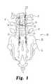
- FIG. 1is a posterior view of a spinal fixation system including a crosslink apparatus relative to the spinal column of a patient.
- FIG. 2is an exploded assembly view of a crosslink device of the crosslink apparatus of FIG. 1 .
- FIG. 3is a cross sectional view of an interconnection device of the crosslink device shown in FIG. 2 when viewed in direction 3 - 3 of FIG. 2 .
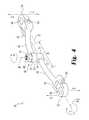
- FIG. 4is a perspective view of the crosslink device in FIG. 2 .
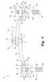
- FIG. 5is a side plan view of the crosslink device relative to spinal implant components of the spinal fixation system of FIG. 1 , with some features shown in phantom.
- FIG. 6is a perspective assembly view of the crosslink device relative with its connection to spinal implant components shown in exploded view.
- FIG. 7is a side plan view of a crosslink device relative to other embodiment spinal implant components of the spinal fixation system of FIG. 1 .
- the present inventionprovides unique orthopedic prosthesis, systems, methods of use and manufacture, devices, instruments, and kits. Incorporated herein by reference in its entirety is U.S. patent application Ser. No. 11/401,822, filed on Apr. 10, 2006, entitled “CROSSLINK INTERCONNECTION OF BONE ATTACHMENT DEVICES”.
- FIG. 1illustrates a posterior spinal fixation system 20 of one embodiment located at a desired skeletal location of a patient. More specifically, as depicted in FIG. 1 , system 20 is affixed to bones B of the spinal column 21 from a posterior approach. Bones B include the sacrum S and several vertebrae V. System 20 generally includes several bone attachment devices 22 and elongate spinal stabilization elements such as rods 23 structured to selectively interconnect with bone attachment devices 22 . In system 20 , bone attachment devices 22 are affixed to various locations of the spinal column 21 and interconnected with rods 23 . Bone attachment devices 22 may also be interconnected by a crosslink apparatus 24 to provide a stable construct for treating spinal disorders. Posterior fixation system 20 may be used for, but is not limited to, treatment of degenerative spondylolisthesis, fracture, dislocation, scoliosis, kyphosis, spinal tumor, and/or a failed previous fusion.
- FIG. 2is an exploded assembly view of a crosslink device 26 of crosslink apparatus 24 in FIG. 1 .
- Crosslink device 26includes a first bridging member 28 with a first connector 52 and a second bridging member 40 with a second connector 54 .
- First and second bridging members 28 , 40can be engaged to one another at ends thereof opposite the respective connectors 52 , 54 with an adjustable linking/interconnection device 66 .
- Cross-link device 26can extend between and interconnect respective ones of the first and second bone attachment devices 22 through which rods 23 are positioned.
- Cross-link device 26can include linking/interconnection device 66 that allows change of the angular orientation between and the length of first and second bridging members 28 , 40 , providing adjustability in the positioning of cross-link device 26 between attachment devices 22 to avoid anatomical structures along the spine.
- Crosslink device 26includes first elongated bridging member 28 having a first end 30 opposite a second end 32 .
- First end 30includes a first socket 34 defined by a pair of outwardly extending prongs 36 and 37 including apertures 38 and 39 transversely formed therethrough.
- Crosslink device 26further includes second elongate bridging member 40 having a first end 42 opposite a second end 44 .
- First end 42includes a second socket 47 defined by a pair of outwardly extending prongs 48 and 49 including apertures 50 and 51 formed transversely therethrough.
- bridging members 28 and 40 between respective first ends 30 and 42 and second ends 32 and 44include an arcuate configuration so that in the operative, implanted position bridging members 28 and 40 are convexly curved away from the spinal column to provide clearance over anatomical structures.
- members 28 and 40may be more or less arcuate and may even be straight.
- First and second sockets 34 , 47are each sized and structured to receive first connector 52 and second connector 54 therein, respectively.
- Each of first connector 52 and second connector 54includes a body 56 and a branch 58 extending from body 56 wherein branch 58 is appropriately sized relative to first socket 34 and second socket 47 and is structured for insertion therein.
- Branch 58further includes an aperture 62 extending transversely therethrough such that when connectors 52 and 54 are inserted into sockets 34 and 47 respectively, aperture 62 of branch 58 aligns with apertures 38 , 39 and 50 , 51 .
- a fulcrum 64 shown in the form of pinmay be inserted through aperture 38 of prong 36 , through aperture 62 , and through aperture 39 of prong 37 to pivotally interconnect connector 52 with socket 34 .
- connector 54may be pivotally interconnected to socket 47 by inserting fulcrum 64 through aperture 50 of prong 48 , through aperture 62 , and then through aperture 51 of prong 49 .
- any of apertures 38 , 39 , 50 , and 51may include threading therein, such that fulcrum 64 may be in the form of a bolt or screw. Fulcrum 64 can also be press fit, welded or otherwise secured to one or both of the prongs of the respective socket. Fulcrum 64 may also be a standard bolt and nut combination or any other device known to those skilled in the art capable of permitting pivotal movement thereabout. It is also contemplated that the arrangement between the branch and socket could be reversed so that one or both of connectors 52 , 54 defines a socket and the respective adjacent end of bridging member 28 , 40 defines a branch pivotally coupled in the socket.
- connectors 52 and 54may pivot freely in an upward or downward direction as indicated by respective Directional Arrows D and E. While connectors 52 and 54 are illustrated as being substantially in the same plane, it is intended that their planar relationship will shift when crosslink device 26 is attached to bone attachment devices 22 having different elevational locations within the body and having different angular orientations relative to one another and relative to the connectors 52 , 54 .
- the ability to adjust the angular orientation of the ends of bridging members 28 , 40 with connectors 52 , 54facilitates attachment of crosslink device 26 between bone attachment devices with an infinite number of relative locations and angular orientations between the bone attachment devices.
- body 56 of connectors 52 and 54includes an aperture 60 therethrough to facilitate engagement with bone attachment devices 22 of FIG. 1 .
- body 56does not an aperture 60 that is completely enclosed.
- an open collar with a slotis defined by each body 56 of connectors 52 and 54 in lieu of the enclosed aperture 60 .
- the structures of connectors 52 and 54have a different means for engaging the respective bone attachment devices 22 .
- the shape and size of bridging members 28 and 40can differ from that depicted as desired for a particular application.
- the connectors 52 , 54can abut against the ends of the respective receiver portions 90 , or may include a cavity to at least partially receive the respective receiver portion 90 therein. It should be further understood that connectors 52 , 54 may rotate around the bone attachment device 22 until finally secured thereto with an engaging member. The rotational adjustability of the connectors 52 , 54 and thus bridging members 28 , 40 with respect to the bone attachment devices further facilitates adjustment in the angular orientation and length of the bridging members 28 , 40 relative to one another.
- Crosslink device 26further includes an adjustable linking/interconnection device 66 having a stem 68 , a fastener 70 , and a sleeve 72 defining a passageway 74 .
- a detailed cross sectional view of interconnection device 66is provided in FIG. 3 that corresponds to the section line 3 - 3 presented in FIG. 2 .
- Sleeve 72is positioned opposite stem 68 , which extends away therefrom.
- Bridging member 40is structured for rotatable engagement with stem 68 and bridging member 28 is structured for translational and rotatable engagement within passageway 74 of sleeve 72 .
- Second end portion 44 of bridging member 40includes end portion 45 that defines a passage 46 therethrough.
- stem 68 of device 66extends through passage 46 .
- passage 46can alternatively be defined as a fork, slot, shim, collar, or blade (just to name a few possibilities) that receives stem 68 instead of the enclosed structure of passage 46 .
- bridging member 40can be moved through a range of rotational positions about axis R 1 , as represented by the rotational motion arrow A.
- Bridging member 28includes second end 32 opposite first end 30 that defines an end portion 33 that extends through passageway 74 of sleeve 72 , and has a range of translational motion along axis T as represented by range segment B in FIG. 4 . Furthermore, passageway 74 and end portion 33 are sized and shaped to facilitate a range of rotational positions about axis R 2 relative to passageway 74 and sleeve 72 as represented by rotational motion arrow C in FIG. 4 .
- fastener 70 including an aperture 76 with internal threading 78is engaged with threading 80 on stem 68 .
- sleeve 72brings end portion 33 into contact with end portion 45 , forming a bearing relationship therebetween that resists movement therebetween.
- bridging members 28 and 40become fixed relative to one another as fastener 70 is tightened on stem 68 to bear against a side of end portion 33 opposite the side in contact with end portion 45 . It should be appreciated that before final tightening, refinements can be made in the relative positioning.
- a bridging constructspans between a pair of bone attachment devices 22 with a selected rotational configuration relative to axes R 1 and R 2 (and ranges A and C) and a selected translational configuration relative to axis T along range segment B.
- axes R 1 and R 2are approximately orthogonal to one another, bridging members 28 , 40 can be angularly adjusted relative to one another about axis R 1 .
- the angular orientation of connectors 52 , 54 relative to anothercan be adjusted by rotation of bridging member 28 about axis R 2 .
- axis R 1is parallel to the view plane, but axis R 2 is perpendicular thereto, being represented by cross hairs.
- Translation axis Tis parallel to axis R 2 , as best shown in FIG. 4 .
- Crosslink apparatus 24includes crosslink device 26 and a pair of bone attachment devices in the form of bone screw 82 and bone screw 84 .
- Bone screws 82 and 84can each have an elongated shaft or stem 86 with a helical threaded portion 88 .
- Stem 86is structured to threadingly engage a passageway prepared in one or more bones or bony structures in a standard manner, and can be provided with cutting flutes or other structure for self-tapping and/or self-drilling capabilities.
- Stem 86can also be cannulated to receive a guidewire to facilitate placement and may further include fenestrations or other openings for placement of bone growth material.
- Bone screw 82 and bone screw 84each have a head or a receiver portion 90 defining a receiving channel 94 between upright arms 92 .
- Arms 92can include an internal threading 98 .
- head 90includes a receiving channel 94 but does not include threading 98 , or may include external threading in addition to or alternatively to threading 98 .
- Receiving channel 94can form a channel structured to passively secure rod 23 in receiver portion 90 without additional securing means for those embodiments including rod 23 .
- Bottom portion 96can be concavely curved and form a portion of a circle to receive the rod in form fitting engagement therein.
- the rodis positioned against a head of a bone screw, or against a cap or crown adjacent a head of a bone screw in receiver portion 90 .
- bone screw 82 and bone screw 84are made of medical grade stainless steel but other embodiments may be composed of, but are not limited to, titanium, a titanium alloy or other metallic alloy, and/or a nonmetallic composition.
- Bone attachment devices 22may be, but are not limited to, multi-axial, poly-axial, uni-axial, uni-planar bone screws where stem 86 and receiver portion 90 are movable relative to one another. In one movable form, stem 86 and receiver portion 90 are engaged together with a “ball and joint” or swivel type of coupling that permits relative movement therebetween during at least some stages of assembly.
- bone attachment devices 22may include one or more hooks to engage an adjacent bony structure such as a pedicle, lamina, spinous process, transverse process, or other bony structure suitable engaged with a spinal hook.
- a multi-axial laminar hook form of device 22can be used in place of screw 82 and/or screw 84 .
- device 22can include a bone attachment structure in the form of a staple, bone plate, interbody fusion device, interbody spacer, spinal anchor, intravertebral fusion device, bone clamp, or other anchor.
- rod 23may be solid or hollow along some or all of its length and/or may be of homogenous or heterogeneous composition.
- Rod 23can be rigid, or be flexible or include one or more flexible portions to permit at least limited spinal motion.
- Rod 23may be substituted with any suitable spinal stabilization element positionable along the spinal column, including plates, tethers, wires, cables, cords, inflatable devices, expandable devices, and formed in place devices, for example.
- FIG. 5further includes two engaging members 100 and 101 structured to secure crosslink device 26 to bone screws 82 and 84 , respectively, or other bone attachment devices.
- Engaging members 100 and 101each include a longitudinal threaded stem 102 , 102 ′, respectively, opposite a head 104 .
- Head 104 of each of engaging members 100 , 101includes a tool engagement cavity 106 .
- Tool engagement cavity 106may be, but is not limited to, a hex or allen wrench configuration. In alternative embodiments, tool engagement may be provided by a differently shaped structure for engagement by an appropriate assembly tool or may be absent.
- engaging members 100 and 101include a frangible, break-away portion which is engaged by a tool to rotate engaging members 100 and 101 into receiver portion 90 until a threshold torque level is reached, at which point the break-away portion fractures, separating from the remaining portions of engaging members 100 , 101 at a pre-determined location.
- FIG. 5illustrates bone screw 82 having rod 23 positioned in receiver portion 90 .
- receiver portion 90 and rod 23may differ in size in relation to one another and/or other components of system 20 .
- engaging member 100is engaged in receiver portion 90
- the end of threaded stem 102can bear against rod 23 and force rod 23 against bottom portion 96 or other structure in receiver portion 90 , securing rod 23 with crosslink device 26 and bone screw 82 in a rigid construct.
- engaging member 101is shown not completely engaged with receiver portion 90 of bone screw 84 in order to aid in the depiction of threading 98 .
- stem 102 ′includes a length extending from head 104 such that its distal end stops at location 91 in receiver portion 90 .
- the distal end of stem 102 ′remains spaced from rod 23 in receiver portion 90 .
- rod 23is free to axially translate and move relative to bone screw 84 and cross-link device 26 while cross-link device 26 and bone screw 84 are rigidly coupled to one another.
- the engaging members 100 , 101may be employed in either or both of bone screws 82 , 84 or other bone attachment device 22 .
- one or both of the connectors 52 , 54may include a structure that contacts the respective adjacent rod 23 when engaging member 101 with stem 102 ′ is engaged to a bone attachment device 22 . Accordingly, when engaging member 101 is tightened, it remains spaced from rod 23 in receiver portion 90 , while connector 52 , 54 includes a recess to receive receiver portion 90 , or includes a structure extending distally therefrom toward rod 23 that contacts and securely engages rod 23 to receiver portion 90 of the bone attachment device.
- FIG. 5shows the top or proximal end of 99 of the receiver portions 90 of bone screw 82 and bone screw 84 in different elevational planes.
- Crosslink device 26is able to fittingly engage with proximal ends 99 of the receiver portions 90 or other structure of the bone attachment device 22 even if at different elevational planes and different angular orientations because connectors 52 and 54 pivot about fulcrum 64 . While not shown, it should be understood that the elevational differences between the proximal ends 99 of bone attachment devices may be greater, smaller, or even the same in alternative embodiments.
- FIG. 6is a perspective assembly view of crosslink apparatus 24 wherein like numerals refer to like features previously described.
- a coupler 107is utilized.
- Coupler 107has first end 108 opposite a second end 109 and includes a longitudinal threaded stem 110 with an internally threaded portion 112 .
- the first end 108is further defined by a tool cooperation portion 114 .
- Longitudinal threaded stem 110 of coupler 107is structured to engage threading 98 when coupler 107 is rotated into receiver portion 90 of bone screws 82 and 84 .
- the embodiment of FIG. 6includes one or more rod(s) 23 through the respective receiver portions 90 of bone screws 82 , 84 .
- Rod(s) 23is/are placed into rod receiving channel 94 and coupler 107 is engaged with threading 98 such that second end 109 bears against rod(s) 23 to create a rigid engagement between receiver portion 90 and rod 23 .
- Internally threaded portion 112is structured to engage, for example, threaded stem 102 of engaging member 100 when engaging member 100 is inserted through aperture 60 of an adjacent one of the connectors 52 and 54 .
- coupler 107is tightened in receiver portion 90 and engaging member 100 is tightened in internally threaded portion 112 , crosslink device 26 is locked in a rigid construct with bone screws 82 and 84 or other bone attachment devices 22 . While bone screw 82 and bone screw 84 are both shown using coupler 107 , it should be understood that in alternative embodiments coupler 107 may be absent from one or both of bone screw 82 and bone screw 84 . It is further contemplated that coupler 107 may be used in alternative bone attachment devices 22 not illustrated in FIG. 6 .
- FIG. 7An alternative embodiment of crosslink apparatus 24 is shown in a side plan view in FIG. 7 where certain hidden features are shown in phantom and where like numerals refer to like features previously described.
- Connector 52 of crosslink device 26is shown connected to a bone attachment device 22 in the form of a laminar hook 116 .
- Laminar hook 116includes a hook portion 118 structured to engage bone or a bony surface and a proximal head or receiver portion 124 .
- Receiver portion 124further includes a receiving channel 126 formed by a pair of upright arms 122 having internal threading 127 disposed therein.
- An engaging member, such as engaging member 100can be passed through aperture 60 and engaged with threading 127 to create a rigid construct between connector 52 and laminar hook 116 and a rod or other elongate element positioned in receiving channel 126 .
- Connector 54is shown connected to a bone attachment device 22 in the form of bone anchor 128 including a distal bone engaging portion 130 opposite a proximally extending post 132 .
- Engaged about post 132is a coupler clamp 134 including a receiver portion 136 .
- the receiver portion 136is a post engagement portion 138 including an aperture 141 through which post 132 extends.
- Coupler clamp 134further includes a rod interface washer 138 and a post interface washer 140 . Disposed on the side of washer 138 and washer 140 facing each other are a set of interdigitating teeth 142 .
- Interdigitating teeth 142are structured to allow lockable positioning of washer 138 and washer 140 such that the angular orientation of rod 23 relative to bone anchor 128 may be altered. However, once engaging member 100 is passed through aperture 60 and fully engaged with a threaded aperture 144 disposed near receiver portion 136 , interdigitating teeth 142 become locked as rod 23 is forced to bias the washers 138 , 140 into contact with one another. This occurs as threaded stem 102 presses against rod 23 forcing washers 138 and 140 together and pulling aperture 141 tight against post 132 to create a rigid construct between connector 54 , rod 23 , and bone anchor 128 . Bone attachment devices 22 including bone anchor 128 and other forms are commercially available, for example, under the trade name TSRH-3D® spinal systems.
- crosslink apparatus 24is free from both engaging members 100 , 101 and/or apertures 60 in connectors 52 , 54 .
- various means for connecting crosslink device 26 with bone attachment devices 22are included.
- the meansmay include, but are not limited to, snap rings, nuts, pins, compression fits, snap fits, clamps, adhesives, and fusions.
- engaging members 100 , 101are shown with externally threaded stems.
- Other embodimentscontemplate engaging members 100 , 101 with other structures for engaging receiver portion 32 , including twist locks, snap fits, interference fits, slide-fits, clamps, expansion fits, and internally threaded stems, for example.
- As the connecting means changethe corresponding structure of connector 52 and connector 54 will change.
- rod 23the manner in which rod 23 is secured to one or both of bone attachment devices 22 will also change.
- cross-link apparatus 24can be composed of medical grade stainless steel.
- Other embodimentsmay be composed of, but are not limited to, titanium, a titanium alloy or other metallic alloy, and/or a nonmetallic composition.
Landscapes
- Health & Medical Sciences (AREA)
- Orthopedic Medicine & Surgery (AREA)
- Life Sciences & Earth Sciences (AREA)
- Surgery (AREA)
- Neurology (AREA)
- Heart & Thoracic Surgery (AREA)
- Engineering & Computer Science (AREA)
- Biomedical Technology (AREA)
- Nuclear Medicine, Radiotherapy & Molecular Imaging (AREA)
- Medical Informatics (AREA)
- Molecular Biology (AREA)
- Animal Behavior & Ethology (AREA)
- General Health & Medical Sciences (AREA)
- Public Health (AREA)
- Veterinary Medicine (AREA)
- Surgical Instruments (AREA)
- Prostheses (AREA)
Abstract
Description
Claims (16)
Priority Applications (6)
| Application Number | Priority Date | Filing Date | Title |
|---|---|---|---|
| US11/401,732US7837714B2 (en) | 2006-04-10 | 2006-04-10 | Methods and devices for the interconnection of bone attachment devices |
| KR1020087027426AKR20090007405A (en) | 2006-04-10 | 2007-04-09 | Methods and devices for the interconnection of bone attachment devices |
| PCT/US2007/066212WO2007121128A1 (en) | 2006-04-10 | 2007-04-09 | Methods and devices for the interconnection of bone attachment devices |
| CNA2007800139008ACN101426437A (en) | 2006-04-10 | 2007-04-09 | Methods and devices for the interconnection of bone attachment devices |
| EP07760301AEP2004077A1 (en) | 2006-04-10 | 2007-04-09 | Methods and devices for the interconnection of bone attachment devices |
| JP2009505558AJP5006926B2 (en) | 2006-04-10 | 2007-04-09 | Method and apparatus for interconnecting bone appliers |
Applications Claiming Priority (1)
| Application Number | Priority Date | Filing Date | Title |
|---|---|---|---|
| US11/401,732US7837714B2 (en) | 2006-04-10 | 2006-04-10 | Methods and devices for the interconnection of bone attachment devices |
Publications (2)
| Publication Number | Publication Date |
|---|---|
| US20070270808A1 US20070270808A1 (en) | 2007-11-22 |
| US7837714B2true US7837714B2 (en) | 2010-11-23 |
Family
ID=38480563
Family Applications (1)
| Application Number | Title | Priority Date | Filing Date |
|---|---|---|---|
| US11/401,732Active2028-01-11US7837714B2 (en) | 2006-04-10 | 2006-04-10 | Methods and devices for the interconnection of bone attachment devices |
Country Status (6)
| Country | Link |
|---|---|
| US (1) | US7837714B2 (en) |
| EP (1) | EP2004077A1 (en) |
| JP (1) | JP5006926B2 (en) |
| KR (1) | KR20090007405A (en) |
| CN (1) | CN101426437A (en) |
| WO (1) | WO2007121128A1 (en) |
Cited By (49)
| Publication number | Priority date | Publication date | Assignee | Title |
|---|---|---|---|---|
| US20090105765A1 (en)* | 2007-10-23 | 2009-04-23 | Intrepid Orthopedics, Llc | Spinal rod cross connector |
| US20100160981A1 (en)* | 2008-12-22 | 2010-06-24 | Butler Michael S | Posterior Cervical Cross Connector Assemblies |
| US20100198259A1 (en)* | 2006-04-10 | 2010-08-05 | Warsaw Orthopedic, Inc. | Crosslink Interconnection of Bone Attachment Devices |
| US20120071926A1 (en)* | 2010-09-16 | 2012-03-22 | Jani Mehul R | Transverse Connector |
| US20120095510A1 (en)* | 2010-10-18 | 2012-04-19 | Raj Nihalani | Cross connectors |
| US20130165976A1 (en)* | 2011-12-23 | 2013-06-27 | Joshua Gunn | Transverse crosslink device |
| US8491641B2 (en) | 2010-09-28 | 2013-07-23 | Spinofix, Inc. | Pedicle screws and dynamic adaptors |
| US20140148858A1 (en)* | 2011-03-04 | 2014-05-29 | Zimmer Spine, Inc. | Transverse connector |
| US8828058B2 (en) | 2008-11-11 | 2014-09-09 | Kspine, Inc. | Growth directed vertebral fixation system with distractible connector(s) and apical control |
| US20140358181A1 (en)* | 2007-01-29 | 2014-12-04 | Samy Abdou | Spinal stabilization systems and methods of use |
| US8920472B2 (en) | 2011-11-16 | 2014-12-30 | Kspine, Inc. | Spinal correction and secondary stabilization |
| US8956361B2 (en) | 2011-12-19 | 2015-02-17 | Amendia, Inc. | Extended tab bone screw system |
| US9011491B2 (en) | 2004-08-03 | 2015-04-21 | K Spine, Inc. | Facet device and method |
| US9168071B2 (en) | 2009-09-15 | 2015-10-27 | K2M, Inc. | Growth modulation system |
| US9173681B2 (en) | 2009-03-26 | 2015-11-03 | K2M, Inc. | Alignment system with longitudinal support features |
| US20160030091A1 (en)* | 2012-11-06 | 2016-02-04 | Globus Medical, Inc. | Low profile connectors |
| US9333009B2 (en) | 2011-06-03 | 2016-05-10 | K2M, Inc. | Spinal correction system actuators |
| US9451987B2 (en) | 2011-11-16 | 2016-09-27 | K2M, Inc. | System and method for spinal correction |
| US9468469B2 (en) | 2011-11-16 | 2016-10-18 | K2M, Inc. | Transverse coupler adjuster spinal correction systems and methods |
| US9468471B2 (en) | 2013-09-17 | 2016-10-18 | K2M, Inc. | Transverse coupler adjuster spinal correction systems and methods |
| US9468468B2 (en) | 2011-11-16 | 2016-10-18 | K2M, Inc. | Transverse connector for spinal stabilization system |
| US20160367292A1 (en)* | 2012-11-06 | 2016-12-22 | Globus Medical, Inc. | Low profile connectors |
| US9707015B2 (en) | 2014-01-14 | 2017-07-18 | Life Spine, Inc. | Implant for immobilizing cervical vertebrae |
| US9763703B2 (en) | 2015-05-05 | 2017-09-19 | Degen Medical, Inc. | Cross connectors, kits, and methods |
| US20180042647A1 (en)* | 2016-08-09 | 2018-02-15 | Warsaw Orthopedic, Inc. | Spinal implant system and method |
| US10238432B2 (en) | 2017-02-10 | 2019-03-26 | Medos International Sàrl | Tandem rod connectors and related methods |
| US20190117272A1 (en)* | 2017-10-22 | 2019-04-25 | Astura Medical Inc. | Variable screw top cross connector |
| US10321939B2 (en) | 2016-05-18 | 2019-06-18 | Medos International Sarl | Implant connectors and related methods |
| US10398476B2 (en) | 2016-12-13 | 2019-09-03 | Medos International Sàrl | Implant adapters and related methods |
| US10492835B2 (en) | 2016-12-19 | 2019-12-03 | Medos International Sàrl | Offset rods, offset rod connectors, and related methods |
| US10517647B2 (en) | 2016-05-18 | 2019-12-31 | Medos International Sarl | Implant connectors and related methods |
| US10543107B2 (en) | 2009-12-07 | 2020-01-28 | Samy Abdou | Devices and methods for minimally invasive spinal stabilization and instrumentation |
| US10548740B1 (en) | 2016-10-25 | 2020-02-04 | Samy Abdou | Devices and methods for vertebral bone realignment |
| US10561454B2 (en) | 2017-03-28 | 2020-02-18 | Medos International Sarl | Articulating implant connectors and related methods |
| US10575961B1 (en) | 2011-09-23 | 2020-03-03 | Samy Abdou | Spinal fixation devices and methods of use |
| US10695105B2 (en) | 2012-08-28 | 2020-06-30 | Samy Abdou | Spinal fixation devices and methods of use |
| US10702311B2 (en) | 2011-11-16 | 2020-07-07 | K2M, Inc. | Spinal correction and secondary stabilization |
| US10857003B1 (en) | 2015-10-14 | 2020-12-08 | Samy Abdou | Devices and methods for vertebral stabilization |
| US10893894B2 (en) | 2019-04-24 | 2021-01-19 | Aesculap Implant Systems, Llc | Transverse coupling for surgical implant extensions |
| US10918498B2 (en) | 2004-11-24 | 2021-02-16 | Samy Abdou | Devices and methods for inter-vertebral orthopedic device placement |
| US10966761B2 (en) | 2017-03-28 | 2021-04-06 | Medos International Sarl | Articulating implant connectors and related methods |
| US10973648B1 (en) | 2016-10-25 | 2021-04-13 | Samy Abdou | Devices and methods for vertebral bone realignment |
| US11006982B2 (en) | 2012-02-22 | 2021-05-18 | Samy Abdou | Spinous process fixation devices and methods of use |
| US20210220021A1 (en)* | 2018-05-03 | 2021-07-22 | K2M, Inc. | Head To Head Transverse Connector |
| US11076891B2 (en)* | 2019-06-23 | 2021-08-03 | Premia Spine Ltd. | Bi-directional motion spinal implant |
| US11076890B2 (en) | 2017-12-01 | 2021-08-03 | Medos International Sàrl | Rod-to-rod connectors having robust rod closure mechanisms and related methods |
| US20210290272A1 (en)* | 2015-12-23 | 2021-09-23 | Xiangyang Ma | Customized posterior atlantoaxial reduction fixatorwith screws and rods |
| US11173040B2 (en) | 2012-10-22 | 2021-11-16 | Cogent Spine, LLC | Devices and methods for spinal stabilization and instrumentation |
| US11179248B2 (en) | 2018-10-02 | 2021-11-23 | Samy Abdou | Devices and methods for spinal implantation |
Families Citing this family (35)
| Publication number | Priority date | Publication date | Assignee | Title |
|---|---|---|---|---|
| US8480712B1 (en) | 2004-01-06 | 2013-07-09 | Nuvasive, Inc. | System and method for performing spinal fixation |
| US8496686B2 (en)* | 2005-03-22 | 2013-07-30 | Gmedelaware 2 Llc | Minimally invasive spine restoration systems, devices, methods and kits |
| US8926667B2 (en)* | 2007-02-09 | 2015-01-06 | Transcendental Spine, Llc | Connector |
| US8926669B2 (en)* | 2007-02-27 | 2015-01-06 | The Center For Orthopedic Research And Education, Inc. | Modular polyaxial pedicle screw system |
| US8167912B2 (en) | 2007-02-27 | 2012-05-01 | The Center for Orthopedic Research and Education, Inc | Modular pedicle screw system |
| GB0707285D0 (en)* | 2007-04-17 | 2007-05-23 | Burke John | Implantable apparatus for modulation of skeletal growth |
| US20090112266A1 (en)* | 2007-10-25 | 2009-04-30 | Industrial Technology Research Institute | Spinal dynamic stabilization device |
| US8197515B2 (en)* | 2008-02-18 | 2012-06-12 | Expanding Orthopedics Inc. | Cross-connector assembly |
| US9060813B1 (en) | 2008-02-29 | 2015-06-23 | Nuvasive, Inc. | Surgical fixation system and related methods |
| EP2352449B1 (en) | 2008-11-03 | 2018-02-21 | Synthes GmbH | Adjustable rod assembly |
| GB0822507D0 (en)* | 2008-12-10 | 2009-01-14 | Karnezis Ioannis | Surgical device for correction of spinal deformities |
| US8246657B1 (en) | 2009-06-29 | 2012-08-21 | Nuvasive, Inc. | Spinal cross connector |
| WO2011022723A1 (en)* | 2009-08-21 | 2011-02-24 | K2M, Inc. | Transverse rod connector |
| US9827013B2 (en) | 2009-12-08 | 2017-11-28 | Concept Spine Ltd. | Surgical device for correction of spinal deformities |
| US9198696B1 (en) | 2010-05-27 | 2015-12-01 | Nuvasive, Inc. | Cross-connector and related methods |
| KR101030065B1 (en)* | 2010-07-23 | 2011-04-19 | 주식회사 지에스메디칼 | Transverse rod connector |
| US9247964B1 (en) | 2011-03-01 | 2016-02-02 | Nuasive, Inc. | Spinal Cross-connector |
| US9387013B1 (en) | 2011-03-01 | 2016-07-12 | Nuvasive, Inc. | Posterior cervical fixation system |
| CN102160814A (en)* | 2011-03-22 | 2011-08-24 | 邱勇 | Spinal resetting device |
| US9339309B1 (en) | 2012-10-11 | 2016-05-17 | Nuvasive, Inc. | Systems and methods for inserting cross-connectors |
| US9700435B2 (en) | 2013-03-14 | 2017-07-11 | Warsaw Orthopedic, Inc. | Surgical delivery system and method |
| US20140277146A1 (en)* | 2013-03-15 | 2014-09-18 | Blackstone Medical, Inc. | Cross-braced bilateral spinal rod connector |
| CN103381105B (en)* | 2013-06-06 | 2015-09-30 | 雷伟 | A kind of waist ilium joint control and waist ilium associating fixing means thereof |
| KR101694594B1 (en)* | 2014-12-09 | 2017-01-10 | 한림대학교 산학협력단 | Screw guide device for control for surgical treatment |
| TW201707653A (en)* | 2015-08-18 | 2017-03-01 | Pao Nan Biotech Co Ltd | Apparatus for preventing resected fibula sections from bone mergence and connection capable of effectively preventing resected fibula from rigid re-mergence |
| US10987129B2 (en) | 2015-09-04 | 2021-04-27 | Medos International Sarl | Multi-shield spinal access system |
| US11744447B2 (en) | 2015-09-04 | 2023-09-05 | Medos International | Surgical visualization systems and related methods |
| US11439380B2 (en) | 2015-09-04 | 2022-09-13 | Medos International Sarl | Surgical instrument connectors and related methods |
| CN113143355A (en) | 2015-09-04 | 2021-07-23 | 美多斯国际有限公司 | Multi-shield spinal access system |
| US11672562B2 (en) | 2015-09-04 | 2023-06-13 | Medos International Sarl | Multi-shield spinal access system |
| US12150636B2 (en) | 2015-09-04 | 2024-11-26 | Medos International Sárl | Surgical instrument connectors and related methods |
| US10905473B2 (en) | 2016-02-15 | 2021-02-02 | Asro Medical | Transverse, and surgical instrument |
| KR20220059861A (en)* | 2020-11-03 | 2022-05-10 | 주식회사 솔고 바이오메디칼 | Cross link device for cervical spine |
| US11331125B1 (en) | 2021-10-07 | 2022-05-17 | Ortho Inventions, Llc | Low profile rod-to-rod coupler |
| CN114404010A (en)* | 2021-12-23 | 2022-04-29 | 山东师范大学 | Adjustable vertebral lamina hook internal fixation device for lumbar isthmus fissure |
Citations (41)
| Publication number | Priority date | Publication date | Assignee | Title |
|---|---|---|---|---|
| US4957495A (en)* | 1987-04-01 | 1990-09-18 | Patrick Kluger | Device for setting the spinal column |
| US5084049A (en) | 1989-02-08 | 1992-01-28 | Acromed Corporation | Transverse connector for spinal column corrective devices |
| US5133716A (en) | 1990-11-07 | 1992-07-28 | Codespi Corporation | Device for correction of spinal deformities |
| AU1637292A (en) | 1991-05-17 | 1992-11-19 | Philippe Lapresele | Interconnecting device able to lock spinal osteosynthesis fastener |
| US5261913A (en) | 1989-07-26 | 1993-11-16 | J.B.S. Limited Company | Device for straightening, securing, compressing and elongating the spinal column |
| US5522816A (en) | 1994-03-09 | 1996-06-04 | Acromed Corporation | Transverse connection for spinal column corrective devices |
| US5607425A (en) | 1993-10-08 | 1997-03-04 | Rogozinski; Chaim | Apparatus, method and system for the treatment of spinal conditions |
| US5624442A (en) | 1990-04-26 | 1997-04-29 | Cross Medical Products, Inc. | Transverse link for use with a spinal implant system |
| US5630816A (en) | 1995-05-01 | 1997-05-20 | Kambin; Parviz | Double barrel spinal fixation system and method |
| US5667507A (en) | 1995-12-04 | 1997-09-16 | Fastenetix, Llc | Compression locking variable length cross-link device for use with dual rod apparatus |
| US5707372A (en) | 1996-07-11 | 1998-01-13 | Third Millennium Engineering, Llc. | Multiple node variable length cross-link device |
| US5709684A (en) | 1995-12-04 | 1998-01-20 | Fastenetix, Llc | Advanced compression locking variable length cross-link device |
| US5752955A (en) | 1995-10-30 | 1998-05-19 | Fastenetix, L.L.C. | Sliding shaft variable length cross-link device for use with dual rod apparatus |
| US5885284A (en)* | 1996-07-11 | 1999-03-23 | Third Millennium Engineering, L.L.C. | Hinged variable length cross-link device |
| US5980521A (en) | 1995-03-30 | 1999-11-09 | Sdgi Holdings,Inc. | Top-tightening transverse connector for a spinal fixation system |
| US5980523A (en) | 1998-01-08 | 1999-11-09 | Jackson; Roger | Transverse connectors for spinal rods |
| US6217578B1 (en) | 1999-10-19 | 2001-04-17 | Stryker Spine S.A. | Spinal cross connector |
| US6238396B1 (en) | 1999-10-07 | 2001-05-29 | Blackstone Medical, Inc. | Surgical cross-connecting apparatus and related methods |
| US6261288B1 (en) | 2000-02-08 | 2001-07-17 | Roger P. Jackson | Implant stabilization and locking system |
| US6264658B1 (en) | 1998-07-06 | 2001-07-24 | Solco Surgical Instruments Co., Ltd. | Spine fixing apparatus |
| US6283967B1 (en) | 1999-12-17 | 2001-09-04 | Synthes (U.S.A.) | Transconnector for coupling spinal rods |
| US6432108B1 (en) | 2000-01-24 | 2002-08-13 | Depuy Orthopaedics, Inc. | Transverse connector |
| WO2002076315A1 (en) | 2001-03-26 | 2002-10-03 | Ferree Bret A | Spinal alignment apparatus and methods |
| WO2003030759A2 (en) | 2001-10-09 | 2003-04-17 | Synthes (U.S.A.) | Adjustable fixator |
| US20030114853A1 (en) | 2001-10-12 | 2003-06-19 | Ian Burgess | Polyaxial cross connector |
| US20030114852A1 (en)* | 2001-01-12 | 2003-06-19 | Lutz Biedermann | Connector element for bone rods or spinal rods |
| US20030153914A1 (en) | 2002-02-08 | 2003-08-14 | Showa Ika Kohgyo Co., Ltd. | Rod distance retainer |
| US6699248B2 (en) | 2002-05-09 | 2004-03-02 | Roger P. Jackson | Multiple diameter tangential set screw |
| US20040049188A1 (en) | 2002-09-09 | 2004-03-11 | Depuy Acromed, Inc. | Snap-on spinal rod connector |
| US20040116928A1 (en)* | 2002-10-28 | 2004-06-17 | Young J. Stewart | Multi-axial, cross-link connector system for spinal implants |
| US20040133203A1 (en) | 2002-10-28 | 2004-07-08 | Young J Stewart | Multi-axial, cross-link connector system for spinal implants |
| US6872208B1 (en) | 2000-10-06 | 2005-03-29 | Spinal Concepts, Inc. | Adjustable transverse connector |
| US6877241B2 (en) | 2001-08-17 | 2005-04-12 | Schlumberger Technology Corporation | Measurement of curvature of a subsurface borehole, and use of such measurement in directional drilling |
| US20050090821A1 (en) | 2003-10-22 | 2005-04-28 | Gregory Berrevoets | Crosslink for securing spinal rods |
| US20050101956A1 (en) | 2003-11-10 | 2005-05-12 | Simonson Peter M. | Artificial facet joint and method |
| US6916319B2 (en) | 2000-01-27 | 2005-07-12 | Scient'x | Intervertebral linking device with connecting bar for fixing a linking rod |
| US20050177152A1 (en) | 2004-02-10 | 2005-08-11 | Baynham Bret O. | Cross link system |
| US20050216005A1 (en) | 2001-05-17 | 2005-09-29 | Howland Robert S | Selective axis anchor screw posterior lumbar plating system |
| US20050228326A1 (en)* | 2004-03-31 | 2005-10-13 | Depuy Spine, Inc. | Head-to-head connector spinal fixation system |
| US20060064091A1 (en) | 2004-03-31 | 2006-03-23 | Depuy Spine, Inc. | Rod attachment for head to head cross connector |
| US20070270809A1 (en) | 2006-04-10 | 2007-11-22 | Sdgi Holdings, Inc. | Crosslink interconnection of bone attachment devices |
Family Cites Families (2)
| Publication number | Priority date | Publication date | Assignee | Title |
|---|---|---|---|---|
| JP2001037767A (en)* | 1999-08-02 | 2001-02-13 | Kyowa Tokei Kogyo Kk | Bone adjuster |
| US20050215005A1 (en)* | 2003-03-06 | 2005-09-29 | Lsi Logic Corporation | Capacitor with stoichiometrically adjusted dielectric and method of fabricating same |
- 2006
- 2006-04-10USUS11/401,732patent/US7837714B2/enactiveActive
- 2007
- 2007-04-09EPEP07760301Apatent/EP2004077A1/ennot_activeWithdrawn
- 2007-04-09WOPCT/US2007/066212patent/WO2007121128A1/enactiveApplication Filing
- 2007-04-09JPJP2009505558Apatent/JP5006926B2/ennot_activeExpired - Fee Related
- 2007-04-09KRKR1020087027426Apatent/KR20090007405A/ennot_activeWithdrawn
- 2007-04-09CNCNA2007800139008Apatent/CN101426437A/enactivePending
Patent Citations (49)
| Publication number | Priority date | Publication date | Assignee | Title |
|---|---|---|---|---|
| US4957495A (en)* | 1987-04-01 | 1990-09-18 | Patrick Kluger | Device for setting the spinal column |
| US5084049A (en) | 1989-02-08 | 1992-01-28 | Acromed Corporation | Transverse connector for spinal column corrective devices |
| US5261913A (en) | 1989-07-26 | 1993-11-16 | J.B.S. Limited Company | Device for straightening, securing, compressing and elongating the spinal column |
| US5624442A (en) | 1990-04-26 | 1997-04-29 | Cross Medical Products, Inc. | Transverse link for use with a spinal implant system |
| US5133716A (en) | 1990-11-07 | 1992-07-28 | Codespi Corporation | Device for correction of spinal deformities |
| AU1637292A (en) | 1991-05-17 | 1992-11-19 | Philippe Lapresele | Interconnecting device able to lock spinal osteosynthesis fastener |
| EP0514303A1 (en) | 1991-05-17 | 1992-11-19 | STRYKER CORPORATION (a Michigan corporation) | Lockable connecting device for spiral osteosynthesis anchoring elements |
| US5261907A (en)* | 1991-05-17 | 1993-11-16 | Vignaud Jean L | Interconnecting device able to lock spinal osteosynthesis fasteners |
| US5607425A (en) | 1993-10-08 | 1997-03-04 | Rogozinski; Chaim | Apparatus, method and system for the treatment of spinal conditions |
| US5522816A (en) | 1994-03-09 | 1996-06-04 | Acromed Corporation | Transverse connection for spinal column corrective devices |
| US5980521A (en) | 1995-03-30 | 1999-11-09 | Sdgi Holdings,Inc. | Top-tightening transverse connector for a spinal fixation system |
| US5630816A (en) | 1995-05-01 | 1997-05-20 | Kambin; Parviz | Double barrel spinal fixation system and method |
| US5752955A (en) | 1995-10-30 | 1998-05-19 | Fastenetix, L.L.C. | Sliding shaft variable length cross-link device for use with dual rod apparatus |
| US6139548A (en) | 1995-10-30 | 2000-10-31 | Spinal Concepts, Inc. | Sliding shaft variable length cross-link device for use with dual rod apparatus |
| US5667507A (en) | 1995-12-04 | 1997-09-16 | Fastenetix, Llc | Compression locking variable length cross-link device for use with dual rod apparatus |
| US5709684A (en) | 1995-12-04 | 1998-01-20 | Fastenetix, Llc | Advanced compression locking variable length cross-link device |
| US5707372A (en) | 1996-07-11 | 1998-01-13 | Third Millennium Engineering, Llc. | Multiple node variable length cross-link device |
| US5885284A (en)* | 1996-07-11 | 1999-03-23 | Third Millennium Engineering, L.L.C. | Hinged variable length cross-link device |
| US5980523A (en) | 1998-01-08 | 1999-11-09 | Jackson; Roger | Transverse connectors for spinal rods |
| US20020007183A1 (en) | 1998-07-06 | 2002-01-17 | Solco Surgical Instruments Co., Ltd. | Spine fixing apparatus |
| US6264658B1 (en) | 1998-07-06 | 2001-07-24 | Solco Surgical Instruments Co., Ltd. | Spine fixing apparatus |
| US6592585B2 (en)* | 1998-07-06 | 2003-07-15 | Solco Surgical Instruments Co., Ltd. | Spine fixing apparatus |
| US6238396B1 (en) | 1999-10-07 | 2001-05-29 | Blackstone Medical, Inc. | Surgical cross-connecting apparatus and related methods |
| US6217578B1 (en) | 1999-10-19 | 2001-04-17 | Stryker Spine S.A. | Spinal cross connector |
| US20040176765A1 (en) | 1999-12-17 | 2004-09-09 | Synthes (U.S.A.) | Transconnector for coupling spinal rods |
| US6283967B1 (en) | 1999-12-17 | 2001-09-04 | Synthes (U.S.A.) | Transconnector for coupling spinal rods |
| US6736817B2 (en) | 1999-12-17 | 2004-05-18 | Thomas N. Troxell | Transconnector for coupling spinal rods |
| US6432108B1 (en) | 2000-01-24 | 2002-08-13 | Depuy Orthopaedics, Inc. | Transverse connector |
| US6761721B2 (en) | 2000-01-24 | 2004-07-13 | Depuy Acromed, Inc. | Transverse connector |
| US6916319B2 (en) | 2000-01-27 | 2005-07-12 | Scient'x | Intervertebral linking device with connecting bar for fixing a linking rod |
| US6261288B1 (en) | 2000-02-08 | 2001-07-17 | Roger P. Jackson | Implant stabilization and locking system |
| US6872208B1 (en) | 2000-10-06 | 2005-03-29 | Spinal Concepts, Inc. | Adjustable transverse connector |
| US20030114852A1 (en)* | 2001-01-12 | 2003-06-19 | Lutz Biedermann | Connector element for bone rods or spinal rods |
| WO2002076315A1 (en) | 2001-03-26 | 2002-10-03 | Ferree Bret A | Spinal alignment apparatus and methods |
| US20050216005A1 (en) | 2001-05-17 | 2005-09-29 | Howland Robert S | Selective axis anchor screw posterior lumbar plating system |
| US6877241B2 (en) | 2001-08-17 | 2005-04-12 | Schlumberger Technology Corporation | Measurement of curvature of a subsurface borehole, and use of such measurement in directional drilling |
| WO2003030759A2 (en) | 2001-10-09 | 2003-04-17 | Synthes (U.S.A.) | Adjustable fixator |
| US20030114853A1 (en) | 2001-10-12 | 2003-06-19 | Ian Burgess | Polyaxial cross connector |
| US20030153914A1 (en) | 2002-02-08 | 2003-08-14 | Showa Ika Kohgyo Co., Ltd. | Rod distance retainer |
| US6699248B2 (en) | 2002-05-09 | 2004-03-02 | Roger P. Jackson | Multiple diameter tangential set screw |
| US20040049188A1 (en) | 2002-09-09 | 2004-03-11 | Depuy Acromed, Inc. | Snap-on spinal rod connector |
| US20040133203A1 (en) | 2002-10-28 | 2004-07-08 | Young J Stewart | Multi-axial, cross-link connector system for spinal implants |
| US20040116928A1 (en)* | 2002-10-28 | 2004-06-17 | Young J. Stewart | Multi-axial, cross-link connector system for spinal implants |
| US20050090821A1 (en) | 2003-10-22 | 2005-04-28 | Gregory Berrevoets | Crosslink for securing spinal rods |
| US20050101956A1 (en) | 2003-11-10 | 2005-05-12 | Simonson Peter M. | Artificial facet joint and method |
| US20050177152A1 (en) | 2004-02-10 | 2005-08-11 | Baynham Bret O. | Cross link system |
| US20050228326A1 (en)* | 2004-03-31 | 2005-10-13 | Depuy Spine, Inc. | Head-to-head connector spinal fixation system |
| US20060064091A1 (en) | 2004-03-31 | 2006-03-23 | Depuy Spine, Inc. | Rod attachment for head to head cross connector |
| US20070270809A1 (en) | 2006-04-10 | 2007-11-22 | Sdgi Holdings, Inc. | Crosslink interconnection of bone attachment devices |
Cited By (105)
| Publication number | Priority date | Publication date | Assignee | Title |
|---|---|---|---|---|
| US9451997B2 (en) | 2004-08-03 | 2016-09-27 | K2M, Inc. | Facet device and method |
| US9011491B2 (en) | 2004-08-03 | 2015-04-21 | K Spine, Inc. | Facet device and method |
| US11992423B2 (en) | 2004-11-24 | 2024-05-28 | Samy Abdou | Devices and methods for inter-vertebral orthopedic device placement |
| US10918498B2 (en) | 2004-11-24 | 2021-02-16 | Samy Abdou | Devices and methods for inter-vertebral orthopedic device placement |
| US11096799B2 (en) | 2004-11-24 | 2021-08-24 | Samy Abdou | Devices and methods for inter-vertebral orthopedic device placement |
| US20100198259A1 (en)* | 2006-04-10 | 2010-08-05 | Warsaw Orthopedic, Inc. | Crosslink Interconnection of Bone Attachment Devices |
| US8353934B2 (en)* | 2006-04-10 | 2013-01-15 | Warsaw Orthopedic, Inc. | Crosslink interconnection of bone attachment devices |
| US20140358181A1 (en)* | 2007-01-29 | 2014-12-04 | Samy Abdou | Spinal stabilization systems and methods of use |
| US9060816B2 (en)* | 2007-01-29 | 2015-06-23 | Samy Abdou | Spinal stabilization systems and methods of use |
| US9474554B2 (en)* | 2007-10-23 | 2016-10-25 | Lee A. Strnad | Spinal rod cross connector |
| US20090105765A1 (en)* | 2007-10-23 | 2009-04-23 | Intrepid Orthopedics, Llc | Spinal rod cross connector |
| US10842536B2 (en) | 2008-11-11 | 2020-11-24 | K2M, Inc. | Growth directed vertebral fixation system with distractible connector(s) and apical control |
| US8828058B2 (en) | 2008-11-11 | 2014-09-09 | Kspine, Inc. | Growth directed vertebral fixation system with distractible connector(s) and apical control |
| US9510865B2 (en) | 2008-11-11 | 2016-12-06 | K2M, Inc. | Growth directed vertebral fixation system with distractible connector(s) and apical control |
| US8246665B2 (en)* | 2008-12-22 | 2012-08-21 | Life Spine, Inc. | Posterior cervical cross connector assemblies |
| US20100160981A1 (en)* | 2008-12-22 | 2010-06-24 | Butler Michael S | Posterior Cervical Cross Connector Assemblies |
| US9173681B2 (en) | 2009-03-26 | 2015-11-03 | K2M, Inc. | Alignment system with longitudinal support features |
| US9358044B2 (en) | 2009-03-26 | 2016-06-07 | K2M, Inc. | Semi-constrained anchoring system |
| US11154329B2 (en) | 2009-03-26 | 2021-10-26 | K2M, Inc. | Semi-constrained anchoring system |
| US12137943B2 (en) | 2009-03-26 | 2024-11-12 | K2M, Inc. | Semi-constrained anchoring system |
| US9168071B2 (en) | 2009-09-15 | 2015-10-27 | K2M, Inc. | Growth modulation system |
| US9827022B2 (en) | 2009-09-15 | 2017-11-28 | K2M, Llc | Growth modulation system |
| US10736669B2 (en) | 2009-09-15 | 2020-08-11 | K2M, Inc. | Growth modulation system |
| US10610380B2 (en) | 2009-12-07 | 2020-04-07 | Samy Abdou | Devices and methods for minimally invasive spinal stabilization and instrumentation |
| US10543107B2 (en) | 2009-12-07 | 2020-01-28 | Samy Abdou | Devices and methods for minimally invasive spinal stabilization and instrumentation |
| US11918486B2 (en) | 2009-12-07 | 2024-03-05 | Samy Abdou | Devices and methods for minimally invasive spinal stabilization and instrumentation |
| US10945861B2 (en) | 2009-12-07 | 2021-03-16 | Samy Abdou | Devices and methods for minimally invasive spinal stabilization and instrumentation |
| US10857004B2 (en) | 2009-12-07 | 2020-12-08 | Samy Abdou | Devices and methods for minimally invasive spinal stabilization and instrumentation |
| US8523911B2 (en)* | 2010-09-16 | 2013-09-03 | Globus Medical, Inc. | Transverse connector including locking cap with bearing surface |
| US20120071926A1 (en)* | 2010-09-16 | 2012-03-22 | Jani Mehul R | Transverse Connector |
| US8491641B2 (en) | 2010-09-28 | 2013-07-23 | Spinofix, Inc. | Pedicle screws and dynamic adaptors |
| US20120095510A1 (en)* | 2010-10-18 | 2012-04-19 | Raj Nihalani | Cross connectors |
| US20140148858A1 (en)* | 2011-03-04 | 2014-05-29 | Zimmer Spine, Inc. | Transverse connector |
| US10675062B2 (en) | 2011-06-03 | 2020-06-09 | K2M, Inc. | Spinal correction system actuators |
| US9408638B2 (en) | 2011-06-03 | 2016-08-09 | K2M, Inc. | Spinal correction system actuators |
| US9895168B2 (en) | 2011-06-03 | 2018-02-20 | K2M, Inc. | Spinal correction system actuators |
| US9333009B2 (en) | 2011-06-03 | 2016-05-10 | K2M, Inc. | Spinal correction system actuators |
| US11324608B2 (en) | 2011-09-23 | 2022-05-10 | Samy Abdou | Spinal fixation devices and methods of use |
| US11517449B2 (en) | 2011-09-23 | 2022-12-06 | Samy Abdou | Spinal fixation devices and methods of use |
| US10575961B1 (en) | 2011-09-23 | 2020-03-03 | Samy Abdou | Spinal fixation devices and methods of use |
| US12167973B2 (en) | 2011-09-23 | 2024-12-17 | Samy Abdou | Spinal fixation devices and methods of use |
| US9113959B2 (en) | 2011-11-16 | 2015-08-25 | K2M, Inc. | Spinal correction and secondary stabilization |
| US8920472B2 (en) | 2011-11-16 | 2014-12-30 | Kspine, Inc. | Spinal correction and secondary stabilization |
| US11013538B2 (en) | 2011-11-16 | 2021-05-25 | K2M, Inc. | System and method for spinal correction |
| US10702311B2 (en) | 2011-11-16 | 2020-07-07 | K2M, Inc. | Spinal correction and secondary stabilization |
| US10342581B2 (en) | 2011-11-16 | 2019-07-09 | K2M, Inc. | System and method for spinal correction |
| US9827017B2 (en) | 2011-11-16 | 2017-11-28 | K2M, Inc. | Spinal correction and secondary stabilization |
| US9468469B2 (en) | 2011-11-16 | 2016-10-18 | K2M, Inc. | Transverse coupler adjuster spinal correction systems and methods |
| US9468468B2 (en) | 2011-11-16 | 2016-10-18 | K2M, Inc. | Transverse connector for spinal stabilization system |
| US9451987B2 (en) | 2011-11-16 | 2016-09-27 | K2M, Inc. | System and method for spinal correction |
| US9757157B2 (en) | 2011-11-16 | 2017-09-12 | K2M, Inc. | System and method for spinal correction |
| US8956361B2 (en) | 2011-12-19 | 2015-02-17 | Amendia, Inc. | Extended tab bone screw system |
| US9125691B2 (en)* | 2011-12-23 | 2015-09-08 | Amendia, Inc. | Transverse crosslink device |
| US20130165976A1 (en)* | 2011-12-23 | 2013-06-27 | Joshua Gunn | Transverse crosslink device |
| US11006982B2 (en) | 2012-02-22 | 2021-05-18 | Samy Abdou | Spinous process fixation devices and methods of use |
| US11839413B2 (en) | 2012-02-22 | 2023-12-12 | Samy Abdou | Spinous process fixation devices and methods of use |
| US11559336B2 (en) | 2012-08-28 | 2023-01-24 | Samy Abdou | Spinal fixation devices and methods of use |
| US10695105B2 (en) | 2012-08-28 | 2020-06-30 | Samy Abdou | Spinal fixation devices and methods of use |
| US11918483B2 (en) | 2012-10-22 | 2024-03-05 | Cogent Spine Llc | Devices and methods for spinal stabilization and instrumentation |
| US11173040B2 (en) | 2012-10-22 | 2021-11-16 | Cogent Spine, LLC | Devices and methods for spinal stabilization and instrumentation |
| US20160367292A1 (en)* | 2012-11-06 | 2016-12-22 | Globus Medical, Inc. | Low profile connectors |
| US10335206B2 (en)* | 2012-11-06 | 2019-07-02 | Globus Medical, Inc. | Low profile connectors |
| US20160030091A1 (en)* | 2012-11-06 | 2016-02-04 | Globus Medical, Inc. | Low profile connectors |
| US10485587B2 (en)* | 2012-11-06 | 2019-11-26 | Globus Medical, Inc | Low profile connectors |
| US9468471B2 (en) | 2013-09-17 | 2016-10-18 | K2M, Inc. | Transverse coupler adjuster spinal correction systems and methods |
| US10512488B2 (en) | 2014-01-14 | 2019-12-24 | Life Spine, Inc. | Implant for immobilizing cervical vertebrae |
| US10166046B2 (en) | 2014-01-14 | 2019-01-01 | Life Spine, Inc. | Implant for immobilizing cervical vertebrae |
| US9707015B2 (en) | 2014-01-14 | 2017-07-18 | Life Spine, Inc. | Implant for immobilizing cervical vertebrae |
| US9763703B2 (en) | 2015-05-05 | 2017-09-19 | Degen Medical, Inc. | Cross connectors, kits, and methods |
| US10857003B1 (en) | 2015-10-14 | 2020-12-08 | Samy Abdou | Devices and methods for vertebral stabilization |
| US11246718B2 (en) | 2015-10-14 | 2022-02-15 | Samy Abdou | Devices and methods for vertebral stabilization |
| US20210290272A1 (en)* | 2015-12-23 | 2021-09-23 | Xiangyang Ma | Customized posterior atlantoaxial reduction fixatorwith screws and rods |
| US12150678B2 (en)* | 2015-12-23 | 2024-11-26 | Xiangyang Ma | Customized posterior atlantoaxial reduction fixatorwith screws and rods |
| US10517647B2 (en) | 2016-05-18 | 2019-12-31 | Medos International Sarl | Implant connectors and related methods |
| US11058463B2 (en) | 2016-05-18 | 2021-07-13 | Medos International Sarl | Implant connectors and related methods |
| US11596451B2 (en) | 2016-05-18 | 2023-03-07 | Medos International Sarl | Implant connectors and related methods |
| US10321939B2 (en) | 2016-05-18 | 2019-06-18 | Medos International Sarl | Implant connectors and related methods |
| US10413330B2 (en)* | 2016-08-09 | 2019-09-17 | Warsaw Orthopedic, Inc. | Spinal implant system and method |
| US20180042647A1 (en)* | 2016-08-09 | 2018-02-15 | Warsaw Orthopedic, Inc. | Spinal implant system and method |
| US11752008B1 (en) | 2016-10-25 | 2023-09-12 | Samy Abdou | Devices and methods for vertebral bone realignment |
| US10973648B1 (en) | 2016-10-25 | 2021-04-13 | Samy Abdou | Devices and methods for vertebral bone realignment |
| US10744000B1 (en) | 2016-10-25 | 2020-08-18 | Samy Abdou | Devices and methods for vertebral bone realignment |
| US11259935B1 (en) | 2016-10-25 | 2022-03-01 | Samy Abdou | Devices and methods for vertebral bone realignment |
| US10548740B1 (en) | 2016-10-25 | 2020-02-04 | Samy Abdou | Devices and methods for vertebral bone realignment |
| US11058548B1 (en) | 2016-10-25 | 2021-07-13 | Samy Abdou | Devices and methods for vertebral bone realignment |
| US10398476B2 (en) | 2016-12-13 | 2019-09-03 | Medos International Sàrl | Implant adapters and related methods |
| US11160583B2 (en) | 2016-12-19 | 2021-11-02 | Medos International Sarl | Offset rods, offset rod connectors, and related methods |
| US10492835B2 (en) | 2016-12-19 | 2019-12-03 | Medos International Sàrl | Offset rods, offset rod connectors, and related methods |
| US12150679B2 (en) | 2016-12-19 | 2024-11-26 | Medos International Srl | Offset rods, offset rod connectors, and related methods |
| US10869695B2 (en) | 2017-02-10 | 2020-12-22 | Medos International Sarl | Tandem rod connectors and related methods |
| US11793554B2 (en) | 2017-02-10 | 2023-10-24 | Medos International Sarl | Tandem rod connectors and related methods |
| US10238432B2 (en) | 2017-02-10 | 2019-03-26 | Medos International Sàrl | Tandem rod connectors and related methods |
| US10966761B2 (en) | 2017-03-28 | 2021-04-06 | Medos International Sarl | Articulating implant connectors and related methods |
| US11382676B2 (en) | 2017-03-28 | 2022-07-12 | Medos International Sarl | Articulating implant connectors and related methods |
| US11707304B2 (en) | 2017-03-28 | 2023-07-25 | Medos International Sarl | Articulating implant connectors and related methods |
| US10561454B2 (en) | 2017-03-28 | 2020-02-18 | Medos International Sarl | Articulating implant connectors and related methods |
| US12059187B2 (en) | 2017-03-28 | 2024-08-13 | Medos International Sarl | Articulating implant connectors and related methods |
| US20190117272A1 (en)* | 2017-10-22 | 2019-04-25 | Astura Medical Inc. | Variable screw top cross connector |
| US11076890B2 (en) | 2017-12-01 | 2021-08-03 | Medos International Sàrl | Rod-to-rod connectors having robust rod closure mechanisms and related methods |
| US11911077B2 (en)* | 2018-05-03 | 2024-02-27 | K2M, Inc. | Head to head transverse connector |
| US20210220021A1 (en)* | 2018-05-03 | 2021-07-22 | K2M, Inc. | Head To Head Transverse Connector |
| US11179248B2 (en) | 2018-10-02 | 2021-11-23 | Samy Abdou | Devices and methods for spinal implantation |
| US10893894B2 (en) | 2019-04-24 | 2021-01-19 | Aesculap Implant Systems, Llc | Transverse coupling for surgical implant extensions |
| US11571246B2 (en) | 2019-04-24 | 2023-02-07 | Aesculap Implant Systems, Llc | Transverse coupling for surgical implant extensions |
| US11076891B2 (en)* | 2019-06-23 | 2021-08-03 | Premia Spine Ltd. | Bi-directional motion spinal implant |
Also Published As
| Publication number | Publication date |
|---|---|
| JP5006926B2 (en) | 2012-08-22 |
| KR20090007405A (en) | 2009-01-16 |
| US20070270808A1 (en) | 2007-11-22 |
| CN101426437A (en) | 2009-05-06 |
| JP2009533173A (en) | 2009-09-17 |
| WO2007121128A1 (en) | 2007-10-25 |
| EP2004077A1 (en) | 2008-12-24 |
| WO2007121128B1 (en) | 2008-01-24 |
Similar Documents
| Publication | Publication Date | Title |
|---|---|---|
| US7837714B2 (en) | Methods and devices for the interconnection of bone attachment devices | |
| US8353934B2 (en) | Crosslink interconnection of bone attachment devices | |
| US12121267B2 (en) | Orthopedic tethered implants and system | |
| US7766946B2 (en) | Device for securing spinal rods | |
| US7803174B2 (en) | Dorsal adjusting multi-rod connector | |
| US20200179009A1 (en) | Orthopedic fastener for stabilization and fixation | |
| US10105166B2 (en) | Spinal rod link reducer | |
| US5624442A (en) | Transverse link for use with a spinal implant system | |
| US8915945B2 (en) | Adjustable multi-axial spinal coupling assemblies | |
| USRE39325E1 (en) | Spinal fixation apparatus and method | |
| US7896905B2 (en) | Bone fixation apparatus | |
| US10820929B2 (en) | Revision connectors, systems, and methods thereof | |
| US8313514B2 (en) | Device for interconnection of components in a spinal implant assembly | |
| US20040158247A1 (en) | Polyaxial pedicle screw system | |
| US20030060823A1 (en) | Pedicle screw spinal fixation device | |
| US20080183223A1 (en) | Hybrid jointed bone screw system | |
| US20080015596A1 (en) | Large diameter multiple piece bone anchor assembly | |
| US20080004625A1 (en) | Bone anchor assemblies | |
| US20060149232A1 (en) | Multi-axial bone screw mechanism | |
| JP2007516811A (en) | Bone anchor assembly and method for manufacturing bone anchor assembly | |
| AU1181295A (en) | Transverse link for spinal implant system | |
| US10485587B2 (en) | Low profile connectors | |
| US9743959B2 (en) | Low profile spinal fixation system |
Legal Events
| Date | Code | Title | Description |
|---|---|---|---|
| AS | Assignment | Owner name:SDGI HOLDINGS, INC., DELAWARE Free format text:ASSIGNMENT OF ASSIGNORS INTEREST;ASSIGNORS:DREWRY, TROY D.;NULL, WILLIAM BARRY;PAUL, MARC T.;REEL/FRAME:017773/0682 Effective date:20060405 | |
| AS | Assignment | Owner name:WARSAW ORTHOPEDIC, INC., INDIANA Free format text:MERGER;ASSIGNOR:SDGI HOLDING, INC.;REEL/FRAME:022471/0137 Effective date:20060428 Owner name:WARSAW ORTHOPEDIC, INC.,INDIANA Free format text:MERGER;ASSIGNOR:SDGI HOLDING, INC.;REEL/FRAME:022471/0137 Effective date:20060428 | |
| STCF | Information on status: patent grant | Free format text:PATENTED CASE | |
| CC | Certificate of correction | ||
| FPAY | Fee payment | Year of fee payment:4 | |
| MAFP | Maintenance fee payment | Free format text:PAYMENT OF MAINTENANCE FEE, 8TH YEAR, LARGE ENTITY (ORIGINAL EVENT CODE: M1552) Year of fee payment:8 | |
| MAFP | Maintenance fee payment | Free format text:PAYMENT OF MAINTENANCE FEE, 12TH YEAR, LARGE ENTITY (ORIGINAL EVENT CODE: M1553); ENTITY STATUS OF PATENT OWNER: LARGE ENTITY Year of fee payment:12 |