US7837676B2 - Cardiac ablation devices - Google Patents
Cardiac ablation devicesDownload PDFInfo
- Publication number
- US7837676B2 US7837676B2US10/783,310US78331004AUS7837676B2US 7837676 B2US7837676 B2US 7837676B2US 78331004 AUS78331004 AUS 78331004AUS 7837676 B2US7837676 B2US 7837676B2
- Authority
- US
- United States
- Prior art keywords
- catheter
- balloon
- contrast medium
- ablation
- reflective
- Prior art date
- Legal status (The legal status is an assumption and is not a legal conclusion. Google has not performed a legal analysis and makes no representation as to the accuracy of the status listed.)
- Expired - Lifetime, expires
Links
Images


Classifications
- A—HUMAN NECESSITIES
- A61—MEDICAL OR VETERINARY SCIENCE; HYGIENE
- A61B—DIAGNOSIS; SURGERY; IDENTIFICATION
- A61B17/00—Surgical instruments, devices or methods
- A61B17/22—Implements for squeezing-off ulcers or the like on inner organs of the body; Implements for scraping-out cavities of body organs, e.g. bones; for invasive removal or destruction of calculus using mechanical vibrations; for removing obstructions in blood vessels, not otherwise provided for
- A61B17/22004—Implements for squeezing-off ulcers or the like on inner organs of the body; Implements for scraping-out cavities of body organs, e.g. bones; for invasive removal or destruction of calculus using mechanical vibrations; for removing obstructions in blood vessels, not otherwise provided for using mechanical vibrations, e.g. ultrasonic shock waves
- A61B17/22012—Implements for squeezing-off ulcers or the like on inner organs of the body; Implements for scraping-out cavities of body organs, e.g. bones; for invasive removal or destruction of calculus using mechanical vibrations; for removing obstructions in blood vessels, not otherwise provided for using mechanical vibrations, e.g. ultrasonic shock waves in direct contact with, or very close to, the obstruction or concrement
- A61B17/2202—Implements for squeezing-off ulcers or the like on inner organs of the body; Implements for scraping-out cavities of body organs, e.g. bones; for invasive removal or destruction of calculus using mechanical vibrations; for removing obstructions in blood vessels, not otherwise provided for using mechanical vibrations, e.g. ultrasonic shock waves in direct contact with, or very close to, the obstruction or concrement the ultrasound transducer being inside patient's body at the distal end of the catheter
- A—HUMAN NECESSITIES
- A61—MEDICAL OR VETERINARY SCIENCE; HYGIENE
- A61B—DIAGNOSIS; SURGERY; IDENTIFICATION
- A61B17/00—Surgical instruments, devices or methods
- A61B17/22—Implements for squeezing-off ulcers or the like on inner organs of the body; Implements for scraping-out cavities of body organs, e.g. bones; for invasive removal or destruction of calculus using mechanical vibrations; for removing obstructions in blood vessels, not otherwise provided for
- A61B17/225—Implements for squeezing-off ulcers or the like on inner organs of the body; Implements for scraping-out cavities of body organs, e.g. bones; for invasive removal or destruction of calculus using mechanical vibrations; for removing obstructions in blood vessels, not otherwise provided for for extracorporeal shock wave lithotripsy [ESWL], e.g. by using ultrasonic waves
- A61B17/2251—Implements for squeezing-off ulcers or the like on inner organs of the body; Implements for scraping-out cavities of body organs, e.g. bones; for invasive removal or destruction of calculus using mechanical vibrations; for removing obstructions in blood vessels, not otherwise provided for for extracorporeal shock wave lithotripsy [ESWL], e.g. by using ultrasonic waves characterised by coupling elements between the apparatus, e.g. shock wave apparatus or locating means, and the patient, e.g. details of bags, pressure control of bag on patient
- A—HUMAN NECESSITIES
- A61—MEDICAL OR VETERINARY SCIENCE; HYGIENE
- A61B—DIAGNOSIS; SURGERY; IDENTIFICATION
- A61B17/00—Surgical instruments, devices or methods
- A61B17/00234—Surgical instruments, devices or methods for minimally invasive surgery
- A61B2017/00238—Type of minimally invasive operation
- A61B2017/00243—Type of minimally invasive operation cardiac
- A—HUMAN NECESSITIES
- A61—MEDICAL OR VETERINARY SCIENCE; HYGIENE
- A61B—DIAGNOSIS; SURGERY; IDENTIFICATION
- A61B17/00—Surgical instruments, devices or methods
- A61B2017/00982—General structural features
- A61B2017/00991—Telescopic means
- A—HUMAN NECESSITIES
- A61—MEDICAL OR VETERINARY SCIENCE; HYGIENE
- A61B—DIAGNOSIS; SURGERY; IDENTIFICATION
- A61B17/00—Surgical instruments, devices or methods
- A61B17/22—Implements for squeezing-off ulcers or the like on inner organs of the body; Implements for scraping-out cavities of body organs, e.g. bones; for invasive removal or destruction of calculus using mechanical vibrations; for removing obstructions in blood vessels, not otherwise provided for
- A61B17/22004—Implements for squeezing-off ulcers or the like on inner organs of the body; Implements for scraping-out cavities of body organs, e.g. bones; for invasive removal or destruction of calculus using mechanical vibrations; for removing obstructions in blood vessels, not otherwise provided for using mechanical vibrations, e.g. ultrasonic shock waves
- A61B2017/22027—Features of transducers
- A—HUMAN NECESSITIES
- A61—MEDICAL OR VETERINARY SCIENCE; HYGIENE
- A61B—DIAGNOSIS; SURGERY; IDENTIFICATION
- A61B17/00—Surgical instruments, devices or methods
- A61B17/22—Implements for squeezing-off ulcers or the like on inner organs of the body; Implements for scraping-out cavities of body organs, e.g. bones; for invasive removal or destruction of calculus using mechanical vibrations; for removing obstructions in blood vessels, not otherwise provided for
- A61B2017/22051—Implements for squeezing-off ulcers or the like on inner organs of the body; Implements for scraping-out cavities of body organs, e.g. bones; for invasive removal or destruction of calculus using mechanical vibrations; for removing obstructions in blood vessels, not otherwise provided for with an inflatable part, e.g. balloon, for positioning, blocking, or immobilisation
- A61B2017/22054—Implements for squeezing-off ulcers or the like on inner organs of the body; Implements for scraping-out cavities of body organs, e.g. bones; for invasive removal or destruction of calculus using mechanical vibrations; for removing obstructions in blood vessels, not otherwise provided for with an inflatable part, e.g. balloon, for positioning, blocking, or immobilisation with two balloons
- A—HUMAN NECESSITIES
- A61—MEDICAL OR VETERINARY SCIENCE; HYGIENE
- A61B—DIAGNOSIS; SURGERY; IDENTIFICATION
- A61B17/00—Surgical instruments, devices or methods
- A61B17/22—Implements for squeezing-off ulcers or the like on inner organs of the body; Implements for scraping-out cavities of body organs, e.g. bones; for invasive removal or destruction of calculus using mechanical vibrations; for removing obstructions in blood vessels, not otherwise provided for
- A61B2017/22051—Implements for squeezing-off ulcers or the like on inner organs of the body; Implements for scraping-out cavities of body organs, e.g. bones; for invasive removal or destruction of calculus using mechanical vibrations; for removing obstructions in blood vessels, not otherwise provided for with an inflatable part, e.g. balloon, for positioning, blocking, or immobilisation
- A61B2017/22061—Implements for squeezing-off ulcers or the like on inner organs of the body; Implements for scraping-out cavities of body organs, e.g. bones; for invasive removal or destruction of calculus using mechanical vibrations; for removing obstructions in blood vessels, not otherwise provided for with an inflatable part, e.g. balloon, for positioning, blocking, or immobilisation for spreading elements apart
Definitions
- the present inventionrelates to ablation apparatus and methods and to steerable devices, including those used in cardiac ablation
- Contraction or “beating” of the heartis controlled by electrical impulses generated at nodes within the heart and transmitted along conductive pathways extending within the wall of the heart.
- Certain diseases of the heartknown as cardiac arrhythmias involve abnormal generation or conduction of the electrical impulses.
- One such arrhythmiais atrial fibrillation or “AF.”
- Certain cardiac arrhythmiascan be treated by deliberately damaging the tissue along a path crossing a route of abnormal conduction, either by surgically cutting the tissue or applying energy or chemicals to the tissue, so as to form scar. The scar blocks the abnormal conduction.
- an expansible structureis used as a reflector for directing and focusing ultrasonic waves from an ultrasonic transducer into a region of tissue to be ablated.
- certain preferred embodiments according to that disclosureinclude an expansible structure incorporating a structural balloon which is inflated with a liquid and a reflector balloon inflated with a gas. The balloons share a common wall.
- the balloonsare configured so that the common wall has a generally parabolic shape. Because the liquid in the structural balloon and the gas in the reflector balloon have substantially different acoustic impedances, the interface between the balloons at the common wall is a nearly perfect reflector for ultrasonic waves.
- Ultrasonic wavesare emitted from a small transducer within the structural balloon and passes radially outwardly from the emitter to the reflector. The reflector redirects the ultrasonic waves and focuses it into a ring-like ablation region encircling the central axis of the emitter and balloons. This ablation region is just forward of the structural balloon.
- the ultrasonic waveswill ablate tissue in a region encircling the central axis or forward-to-rearward axis of the balloon structure.
- This arrangementcan be used, for example, to treat atrial fibrillation by ablating a circular region of myocardial tissue encircling the ostium of a pulmonary vein.
- the ablated tissueforms a barrier to abnormal electrical impulses which can be transmitted along the pulmonary veins and, thus, isolates the myocardial tissue of the atrium from the abnormal impulses.
- the ring-like focal regionshould encircle the ostium and should lie in a plane which is parallel or nearly parallel with the inner surface of the heart.
- the structural balloonis provided with a forwardly projecting tip at its central or forward-to-rearward axis, so that by engaging the tip in the lumen of the pulmonary vein, the forward-to-rearward axis of the balloon structure can be placed at the center of the ostium.
- a guide wirecan be threaded into the pulmonary vein. The balloon is then advanced along the guide wire until the tip lodges in the ostium in the pulmonary vein.
- the particular pulmonary vein being treatedhas a main trunk which extends generally perpendicular to the interior surface of the heart wall, and where the ostium has the expected configuration, this arrangement works properly.
- pulmonary veins and their ostiathere is significant variability in the anatomy of the pulmonary veins and their ostia. For example, that portion of the pulmonary vein adjacent the ostium may lie at an oblique angle to the interior surface of the heart wall. In order to engage the tip of the structural balloon in such an ostium, the forward-to-rearward axis of the balloon must be tilted at a comparable angle, so that the ablation region is unintentionally tilted relative to the interior surface of the heart wall. Also, two or more pulmonary veins may join one another close to a common opening or ostium or may be enlarged or shaped so that it is difficult to engage the tip in the ostium. Moreover, even where the patient has the desired, nominal anatomy, it has been difficult to confirm proper placement of the balloon assembly. Thus, still further improvements would be desirable.
- the delicate tissues within the pulmonary veincan be damaged by forcibly engaging structures with these tissues and by moving the engaged structures while the structures are forcibly engaged with the tissues. It would be desirable to provide an improved system and method which does not rely on such forcible engagement to orient the balloon or other ablation device in the desired disposition. Further, it is often necessary or desirable to move an ablation device to several different dispositions within the heart chamber. For example, the treatment plan may require formation of loop-like lesions around the individual ostium of each of several pulmonary veins. It would be desirable to provide apparatus and methods which facilitate such repositioning.
- expansible ablation devicesincluding balloon-based ablation devices
- improvements in construction of expansible ablation deviceswould be helpful.
- Apparatusprovides apparatus for performing cardiac ablation in a mammalian subject.
- Apparatus according to this aspect of the inventionincludes an insertable structure which incorporates a catheter having proximal and distal ends, as well as an ablation device mounted to the catheter adjacent the distal end thereof.
- the ablation deviceis adapted for placement within a chamber of the heart of the subject and is adapted to ablate a region of the cardiac structure bounding the chamber when the ablation device is in an operative configuration.
- the insertable structurealso defines an outlet port open to a distal side of the ablation device, i.e., that side of the ablation device furthest from the proximal end, and further defines a continuous passageway extending from adjacent the proximal end of the catheter.
- the apparatus according to this aspect of the inventionfurther includes a source of a contrast medium adapted for connection to the passageway adjacent the proximal end of the catheter.
- the source of contrast mediumis operative to pass contrast medium through the passageway and into the subject through the outlet port while the ablation device is in its operative condition.
- the ablation deviceincludes an expansible structure which may be, for example, a balloon structure as discussed above.
- the expansible structurehas a collapsed, inoperative state and an expanded state.
- the ablation deviceis in the operative condition when the expansible structure is in its expanded state.
- a methodincludes the step of providing an ablation device in a chamber of the heart of a mammalian subject, such that the device is in an operative configuration with a distal side of the device facing toward a region of the cardiac structure to be ablated, and, while the ablation device is in its operative configuration, injecting a contrast medium into the chamber on the distal side of the ablation device.
- the methodmost desirably further includes obtaining one or more images depicting the contrast medium in at least a portion of the cardiac structure as, for example, by x-ray or fluoroscopic imaging.
- Methods according to this aspect of the inventionallow the physician to confirm placement of the device while the device is in its operative condition as, for example, while a balloon or other expansible structure is in its expanded state. Most preferably, the methods according to this aspect of the invention are performed without introducing a separate catheter to carry the contrast medium, as by using the continuous passageway discussed above in connection with the apparatus.
- the methods according to this aspect of the inventionmay further include the step of adjusting the position of the ablation device, based in part or entirely on the relationship between the ablation device and the cardiac structure observed in the imaging step. These methods allow the physician to position the device during the procedure, without relying on a predetermined mechanical relationship between the device and the cardiac structure.
- Apparatusincludes a catheter and an ultrasonic device having a forward-to-rearward axis.
- the ultrasonic deviceis arranged to emit ultrasonic waves so that the emitted ultrasonic waves are directed into at least a portion of a ring-like region surrounding the forward-to-rearward axis.
- the ablation deviceis mounted to the catheter.
- Apparatus according to this aspect of the inventionincludes a steering system adapted to selectively vary the disposition of the ablation device and, in particular, the disposition of the forward-to-rearward axis of the ablation device relative to the heart of the subject, while the ultrasonic ablation device is disposed in a chamber of the heart of the subject.
- the ultrasonic ablation devicemost preferably includes an expansible structure such as a balloon structure having a collapsed, inoperative state and an expanded state.
- the steering systempreferably is operative to selectively vary the disposition of the ablation device while the expansible structure is in its expanded state as, for example, while a balloon-based expanded structure is in an inflated condition.
- the steering systemis arranged to selectively vary the disposition of the ultrasonic ablation device independently of engagement between the cardiac structure and any element of the apparatus distal to the ultrasonic ablation device.
- the catheterhas a bendable section located proximally or rearwardly of the forward end of the ablation device, and the steering system is arranged to selectively bend this bendable section of the catheter under the control of the physician.
- the expansible structureincludes an internal reinforcing structure having a distal end linked to the expansible structure adjacent the forward end of the expansible structure, and having a proximal end mechanically linked to the expansible structure adjacent the rearward end thereof.
- the reinforcing structuremay include an ultrasonic emitter assembly, as well as an extensible structure.
- the reinforcing structurebecomes relatively flexible when the expansible structure is in a collapsed condition and becomes more rigid when the expansible structure is in its expanded condition.
- this arrangementallows the reinforcing structure to maintain the shape of the expansible structure in its expanded or inflated condition, but facilitates threading of the device through the body to the heart.
- the steering systemmost desirably includes at least one pull wire mechanically connected to the reinforcing structure, typically adjacent the proximal end thereof.
- at least one pull wiremechanically connected to the reinforcing structure, typically adjacent the proximal end thereof.
- a method of cardiac ablationincludes the steps of advancing apparatus including a catheter bearing an ultrasonic ablation device into the subject until the ultrasonic ablation device is within a chamber of the heart and positioning the ultrasonic ablation device in a first disposition within the chamber by selectively varying the disposition of the forward-to-rearward axis of the ultrasonic ablation device relative to the catheter, and then while the ultrasonic ablation device is in this first disposition, ablating the heart wall to form a first lesion by actuating the ablation device to direct ultrasonic waves into at least a portion of a ring-like region surrounding the forward-to-rearward axis of the device.
- the methodalso includes the step of removing the ultrasonic ablation device from the subject.
- the methodfurther includes the step of repositioning the ultrasonic ablation device from the first disposition to a different, second disposition within the chamber by further selectively varying the disposition of the forward-to-rearward axis relative to the catheter, and, while the device is in the second disposition, ablating the heart wall to form a second lesion, again by actuating the ablation device to direct ultrasonic waves into the ring-like region.
- the repositioning and additional ablation stepsare performed prior to removal of the device.
- the deviceremains within the chamber, and most preferably remains in an expanded, operative condition, while it is repositioned. Additional repositioning and actuating steps may be employed as well, so as to form further lesions.
- At least one of the dispositions of the ablation deviceis a so-called “normal” disposition in which the forward-to-rearward axis of the device lies approximately perpendicular to a wall of the heart with at least a major portion of the ring-like ablation region disposed within or in close proximity to the wall of the heart.
- Ablation in this dispositionforms a lesion in the form of at least a substantial portion of a loop.
- At least one of the dispositionsmay be a canted disposition in which the forward-to-rearward axis of the device lies at a substantially non-perpendicular angle to the wall of the heart, so that only a minor portion of the ring-like region is disposed within or in close proximity to the wall of the heart. Ablation in this disposition forms a lesion in the form of only a small portion of a loop, approximating a linear lesion.
- the same toolcan be used to form both loop-like lesions and substantially linear lesions.
- the ablation deviceis arranged to focus the ultrasonic waves into the ring-like ablation region, so that the ultrasonic waves have intensity which increases in the direction of propagation of the energy from the device to the ablation region and decreases in the same direction, beyond the ablation region.
- the ultrasonic wavesare directed indiscriminately into the entire ablation region. In the normal disposition, all or almost all of this energy performs the desirable function of ablating the loop-like lesion.
- the ablation regiontypically are disposed remote from a heart wall to be ablated.
- ultrasonic waves directed into those remote portions of the ablation regionwill pass through the ablation region and will dissipate, typically without damaging other structures.
- an ultrasonic ablation deviceincluding an ultrasonic emitter assembly which has proximal and distal ends.
- the emitter assemblyincludes a tubular piezoelectric element having proximal and distal ends and a tube, referred to herein as the “inside tube,” extending within the tubular piezoelectric element, so that the inside tube and the piezoelectric element cooperatively define an annular passageway extending between the proximal and distal ends of the piezoelectric element.
- the apparatusdesirably further includes a balloon having an interior space. The annular passageway inside the piezoelectric element communicates with the interior of the balloon adjacent the distal end of the emitter assembly.
- the apparatusmost preferably further includes a catheter having proximal and distal ends.
- the catheterhas a first lumen, referred to herein as a principal lumen, most typically disposed adjacent the center of the catheter, and also has first and second additional lumens.
- the principal lumencommunicates with the bore of the inside tube.
- the first additional lumencommunicates with the proximal end of the annular passageway, and the second additional lumen communicates with the interior of the balloon adjacent the proximal end of the emitter assembly.
- the emitter assemblymay include a proximal mounting structure disposed at least partially between the distal end of the catheter and the proximal end of the tubular piezoelectric element.
- the proximal mounting structuredesirably defines a first channel which connects the first additional lumen of the catheter with the annular passageway, a second channel communicating with the second additional lumen of the catheter and a port communicating with the second channel and with the interior of the balloon, so that the second additional lumen communicates with the interior of the balloon through the port.
- the piezoelectric elementcan be cooled by directing liquid through the first additional lumen of the catheter and through the annular channel inside the piezoelectric element.
- the liquidpasses from the annular channel into the interior of the balloon, passes through the interior of the balloon back through the port and into the second additional lumen of the catheter.
- the principal lumen of the catheter and the bore of the inside tubedesirably define a portion of the continuous passageway discussed above. Because the principal lumen is not employed in circulation of the cooling liquid, it remains free for purposes such as introduction of a contrast medium.
- the emitter assemblymay also include a distal mounting element mounted to the distal end of the piezoelectric element.
- the mounting elementsmay be electrically conductive and may serve as electrical pathways to the piezoelectric element.
- a pull wiremay be connected to one of the mounting structures, typically to the proximal mounting structure, so as to provide the desired bending action as discussed above.
- the apparatusmay further include an extensible element.
- the extensible reinforcing elementmay include elements which cooperate with the distal mounting structure.
- Still other aspects of the inventionprovide alternative structures and methods.
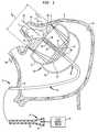
- FIG. 1is a diagrammatic view depicting a catheter and ablation device in accordance with one embodiment of the invention, in conjunction with certain features of a heart.
- FIG. 2is a view similar to FIG. 1 depicting apparatus in accordance with another embodiment of the invention.
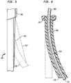
- FIG. 3is a diagrammatic sectional view depicting a portion of a catheter according to one embodiment of the invention.
- FIG. 4is a sectional view taken along line 3 - 3 in FIG. 3 .
- FIG. 5is a fragmentary, diagrammatic elevational view depicting a portion of an apparatus according to yet another embodiment of the present invention.
- FIG. 6is a fragmentary sectional view depicting a portion of apparatus according to a further embodiment of the invention.
- FIG. 7is a view similar to FIG. 6 , but depicting apparatus according to another embodiment of the invention.
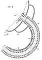
- FIG. 8is a fragmentary sectional view depicting apparatus according to a still further embodiment of the invention.
- FIG. 9is a view similar to FIG. 8 depicting the apparatus of FIG. 8 in another operating condition.
- FIGS. 10 and 11are views similar to FIG. 9 , but depicting apparatus according to yet another embodiment of the invention in two operating conditions.
- FIG. 12is a diagrammatic sectional view depicting a portion of apparatus according to yet another embodiment of the invention.
- FIG. 13is a fragmentary elevational view depicting apparatus according to a still further embodiment of the invention.
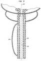
- FIG. 14is a diagrammatic, partially perspective view depicting apparatus according to another embodiment of the invention.
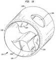
- FIGS. 15 and 16are perspective views depicting a structure used in the embodiment of FIG. 14 .
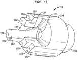
- FIGS. 17 and 18are perspective views depicting another structure used in the embodiment of FIGS. 14-16 .
- FIG. 19is a fragmentary perspective view showing a portion of the structure depicted in FIG. 14 .
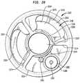
- FIG. 20is a sectional view taking along line 20 - 20 in FIG. 14 .
- FIG. 21is a fragmentary perspective view depicting a portion of the structure shown in FIGS. 14-20 .
- FIG. 22is a diagrammatic sectional view depicting a portion of the structure shown in FIGS. 14-21 in a collapsed condition.
- FIG. 22Ais a fragmentary view on an enlarged scale of the area indicated in FIG. 22 .
- FIG. 23is a view similar to FIG. 22 , but depicting the same portion of the structure in an expanded condition.
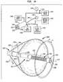
- FIG. 24is a schematic view depicting certain geometrical relationships between the structures of FIGS. 14-23 and a portion of the heart wall during a method in accordance with one embodiment of the invention.
- FIGS. 25 and 26are views similar to FIGS. 22 and 23 , but depicting apparatus according to yet another embodiment of the invention.
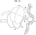
- FIG. 27is a schematic elevational view depicting apparatus according to yet another embodiment of the invention.
- FIG. 28is a schematic view depicting a portion of apparatus according to yet another embodiment of the invention.
- FIG. 29is an elevational view depicting apparatus according to a still further embodiment of the invention.
- FIG. 30is a fragmentary view on an enlarged scale of a portion of the apparatus shown in FIG. 29 .
- FIG. 31is a view similar to FIG. 29 , but depicting apparatus according to a further embodiment of the invention.
- FIG. 32is a schematic diagram depicting apparatus according to yet another embodiment of the invention.
- FIG. 33is a view similar to FIG. 32 , but depicting apparatus according to yet another embodiment of the invention.
- FIG. 34is a fragmentary schematic view depicting apparatus according to a still further embodiment of the invention.
- FIG. 35is a diagrammatic sectional view depicting apparatus to yet another embodiment of the invention.
- FIG. 36is a fragmentary, diagrammatic sectional view depicting apparatus according to yet another embodiment of the invention.
- FIG. 37is a diagrammatic, partially sectional, partially perspective view depicting apparatus according to a still further embodiment of the invention.
- FIG. 38is a diagrammatic sectional view depicting apparatus according to yet another embodiment of the invention.
- FIG. 39is a diagrammatic sectional view depicting exemplary balloon dimensions
- apparatusincludes an insertable structure 10 incorporating an elongated catheter 12 having a proximal end 14 , which remains outside of the body, and a distal end 16 adapted for insertion into the body of the subject.
- proximal end 14As used in this disclosure with reference to structures which are advanced into the body of a subject, the “distal” end of such a structure should be taken as the end which is inserted first into the body and which penetrates to the greatest depth within the body, whereas the proximal end is the end of the structure opposite to the distal end.
- the insertable structure 10also includes an ablation unit 18 mounted to the catheter adjacent distal end 16 .
- Ablation unit 18incorporates a reflector balloon 20 and a structural balloon 22 having a common wall 24 .
- Reflector balloon 20is linked to an inflation lumen (not shown) in catheter 10 , which extends to the proximal end of the catheter and which is connected, during use, to a source of a gas under pressure, such as air or, more preferably, carbon dioxide, as, for example, to a gas-filled hypodermic syringe, so that the reflector balloon can be inflated with a gas.
- Structural balloon 22is connected through a separate inflation lumen (also not shown) to a source of a liquid such as isotonic saline solution, so that structural balloon 22 can be inflated with the liquid.
- a cylindrical ultrasonic emitter 23is mounted within the structural balloon.
- Balloons 20 and 22 , and particularly the common wall 24 separating the balloons,are designed so that in their inflated, operative condition illustrated in FIG. 1 , the balloons are in the form of bodies of revolution about a central or forward-to-rearward axis 26 .
- Emitter 23is cylindrical and is coaxial with the balloons.
- a tube 28extends through the structural balloon at the central axis 26 .
- Tube 28defines a port 29 on or forward of the forward wall 38 of the structural balloon.
- Tube 28communicates with a lumen 30 within catheter 12 .
- Lumen 30extends to the proximal end 14 of the catheter and is provided with a suitable fluid connection such as a Luer hub.
- the bore of tube 28 and lumen 30 of catheter 16form a continuous passageway extending from the outlet port 29 , just distal to the ablation device back to the proximal end 14 of the catheter.
- tube 28may be formed from a material such as an expanded polymer of the type commonly used in vascular grafts, so that the interior bore of the tube remains patent when the tube is stretched.
- a coil spring 34may be provided within the structural balloon, such that the coil spring surrounds tube 28 .
- a reinforcing structurewhich may include one or more rigid tubes of metal or a rigid polymer such as polyether ether ketone (“PEEK”) 36 desirably surrounds tube 28 and spring 34 .
- PEEKpolyether ether ketone
- the springis compressed when the balloons are in the inflated, operative state.
- the springexpands and moves the forward wall 38 of the structural balloon in the forward or distal direction F (up and to the left, as seen in FIG. 1 ) relative to the rearward or proximal end of the balloon and relative to the catheter 12 , thereby collapsing the balloon in a radial direction, and also twists the balloons about axis 26 to facilitate radial collapse and formation of a small, radially compact unit for withdrawal from the patient.
- the springis compressed and reinforcing element 36 engages a rigid mounting 40 attached to the distal end 16 of the catheter, which mounting also holds ultrasonic emitter 23 . This assures that the axis 26 of the balloon structure is precisely aligned with the axis of the emitter and reinforces the balloon against deflection transverse to the axis 26 .
- the tubular reinforcing element 36abuts the distal end of the mounting 40 .
- the mountingis telescopically received within the tubular reinforcing element.
- the tubular reinforcing element 36moves proximally or rearwardly so that the distal end of the mounting 40 enters into the tubular reinforcing element before the balloons are fully inflated.
- the tubular reinforcing elementremains slightly distal or forward of the transducer 23 or else abuts the distal end of the transducer. Telescopic engagement between the mounting and the reinforcing element helps prevent kinking or displacement of the structure transverse to axis 26 when the structure is in a partially-inflated or fully-inflated condition.
- the common wall 24 separating the balloonsforms an active, reflective interface.
- This active interfacedesirably has the form of a surface of revolution of a parabolic section around the central axis 26 .
- ultrasonic waves emitted by emitter 23are directed radially outwardly away from axis 26 and impinge on the parabolic active interface 24 , where it is reflected forwardly and slightly outwardly away from axis 26 and focused so that the ultrasonic waves emitted along various paths mutually reinforces within a ring-like ablation region A, just forward of the forward wall 38 of the structural balloon encircling axis 26 .
- the focused ultrasonic waves in this regioncan effectively ablate myocardial tissue and form a substantial conduction block extending through the heart wall in a relatively short time, typically about a minute or less.
- the apparatusis positioned within a chamber of the heart as, for example, within the left atrium LA of a subject to be treated.
- a guide sheath(not shown) is advanced through the venous system into the right atrium and through the septum separating the right atrium and left atrium, so that the guide sheath provides access to the left atrium.
- the apparatusis advanced through the guide sheath with the balloons in a deflated condition.
- the threading operationmay be performed by first threading a guide wire (not shown) into the heart, then advancing the guide sheath (not shown) over the guide wire, and then advancing the insertable structure 10 , with the balloons in a deflated condition, over the guide wire, and through the guide sheath.
- the guide wirepasses through tube 28 and through lumen 30 .
- the correct positioning of the ablation devicecan be verified by the use of a contrast medium such as an x-ray contrast medium.
- a contrast mediumsuch as an x-ray contrast medium.
- the guide wiremay be removed and lumen 30 may be connected, as by Luer fitting 32 to a source 44 of an x-ray contrast medium as, for example, a hypodermic syringe filled with the contrast medium.
- the contrast mediumis injected through lumen 30 and passes through the bore of tube 28 and out through port 29 at the forward wall 38 of the structural balloon.
- the injected contrast medium Chas sufficient velocity to carry it distally, into the ostium and into the pulmonary vein.
- the blood flow in the pulmonary vein PVdirected back toward the ostium and into the left atrium LA, carries the contrast medium back into the left atrium and around the ablation device.
- the patientis imaged using an x-ray imaging modality, most preferably a fluoroscope.
- an x-ray imaging modalitymost preferably a fluoroscope. This allows the physician to immediately visualize the shape and size of the ostium and the position of the ablation device relative to the ostium and relative to the heart wall W.
- the physicianactuates the ultrasonic emitter 23 to emit the ultrasonic waves and ablate the tissue of the heart wall.
- a thin, tubular stylet 50( FIG. 2 ) having an outlet port at its distal end 52 is threaded through the continuous passageway defined by lumen 30 and by the bore of tube 28 , so that the distal end 52 of the stylet projects forwardly to the distal end of the balloon.
- the distal end of the styletdoes not project substantially beyond the distal end of the balloon, and hence cannot extend substantially into the pulmonary vein. Therefore the stylet cannot damage the lining of the pulmonary vein.
- the proximal end 54 of the tubular styletis equipped with a connection such as a hub 56 which, in turn, is connected to the contrast medium source 44 .
- Stylet 50may serve as the guide wire used in threading the assembly into the patient.
- stylet 50may be placed prior to catheter 12 and ablation device 18 .
- the connection at proximal end 54may incorporate a removable hub so that the catheter and ablation device assembly may be threaded over the stylet and then, after the catheter is in place, hub 56 may be added to the proximal end of the stylet.
- the assemblymay be threaded using a conventional guide wire which is then removed and replaced by the stylet.
- the stylet 50may be relatively stiff, so that the stylet positions the ablation device relative to the pulmonary vein and relative to the heart.
- Positioning the balloon at the PV ostium with a styletis advantageous if there is no clear PV main trunk or the axis of the trunk of the PV is not substantially perpendicular to the wall of the atrium.
- the distal end 52 of the tubular stylet 50defines an outlet port for the contrast medium or the distal side of the ablation device.
- the contrast mediumintroduced through the port.
- the contrast medium CWhen the contrast medium C is introduced into the patient through this port, it permits visualization of the ablation device 18 , pulmonary vein PV, ostium OS and heart wall W, in the manner discussed above, thereby allowing the physician to confirm proper position of the device.
- a guide wire having an outside diameter smaller than the inside diameter of the catheter lumen 30 and smaller than tube 28may be left in place while contrast medium is introduced through the continuous passageway defined by the lumen and tube. Because the guide wire does not completely occlude the passageway, the contrast medium can flow through the passageway and pass out of the port 29 in the manner discussed above with reference to FIG. 1 .
- the ablation device 18may be positioned so that the distal wall 38 abuts the heart wall W in the vicinity of the pulmonary vein ostium and thus substantially occludes and thus substantially blocks flow between the pulmonary vein PV and the heart chamber itself.
- Contrast mediumis injected through port 29 of the ablation device itself as discussed with reference to FIG. 1 , or through the port 52 of a hollow style as discussed with reference to FIG. 2 , while the ablation device is in this blocking position.
- Thisincreases the concentration of the contrast medium within the pulmonary vein and ostium, and thus facilitates imaging of pulmonary vein and ostium and adjacent structures with a minimal amount of contrast medium.
- the catheter and ablation devicemay be retracted after acquiring an image of the ostium and vein, allowing the contrast medium to flow into the atrium, and further images may be acquired.
- a significant advantage of the procedures discussed above with reference to FIGS. 1 and 2is that disposition of the ablation device relative to anatomical structures can be verified while the ablation device is in its inflated, operative condition. Such verification can be performed immediately before, during or after application of ultrasonic waves.
- the ultrasonic waveswill propagate effectively through typical liquid x-ray contrast media, inasmuch as the media have acoustic impedance similar to that of other aqueous liquids. There is no need to move any portion of the ablation device or catheter during introduction of the contrast medium and visualization.
- positioning of the ablation device within the heartdesirably includes selectively controlling the disposition of the forward-to-rearward axis 26 of the device relative to the patient's heart. That is, the position of the forward-to-rearward axis desirably can be controlled by the physician to at least some degree.
- the devicemay be arranged so that the physician can selectively reorient the forward-to-rearward axis 24 of the ablation device through a range of motion as, for example, through the range between disposition indicated in solid lines by axis 24 and the disposition indicated in broken lines by axis 24 ′.
- the assemblycan be provided with one or more devices for selectively varying the curvature of a bendable region 60 of the catheter just proximal to the ablation device.
- the catheteris provided with one or more pull wires 64 .
- Each such pull wireextends from the proximal end 14 of the catheter in a bore or lumen 66 dimensioned to provide a free-running fit for the pull wire.
- Each pull wirehas a distal end 68 fastened to the catheter wall.
- the distal ends of the pull wiresare disposed at or distal to the bendable region 60 .
- the bendable region 60can be bent in the direction toward that particular pull wire.
- the particular embodiment illustratedhas four pull wires disposed in two sets lying in orthogonal planes.
- the first setincludes pull wires 64 A and 64 B, whereas the second set includes pull wires 64 C and 64 D.
- a lesser number of pull wirescan be used.
- a version with three pull wiresalso permits selective bending in any direction
- a version with two diametrically opposite pull wirespermits selective bending in either of two opposite directions in a single plane.
- only a single pull wireis provided to provide bending in only a single direction.
- the catheter itself, or at least the bendable region 60may be resilient so that it tends to return to a predetermined configuration, such as a straight configuration, when the single pull wire is released.
- the cathetermay be “torqueable” or arranged to transmit rotation in the direction around the central axis 70 of the catheter itself. In such an arrangement, combined bending of region 60 and rotation of the catheter about it own axis 70 allows movement of the forward-to-rearward axis of the ablation device towards essentially any desired disposition.
- the lumens 66 containing the pull wires 64may be provided with coil springs (not shown) lining the lumens, so that each pull wire extends though the interior of one such coil spring.
- the turns of each coil springform a low-friction liner within the associated lumen.
- the coil springscan provide additional structural reinforcement and resilience to the catheter.
- the bendable section 160 of the catheteris attached to one or more pull wires 164 which extend outside of the catheter at the bendable section itself.
- Each such pull wiremay extend through a bore 165 in the catheter proximal to the bendable section.
- the bendable sectioncan be deformed to the bent configuration shown in broken lines at 160 ′.
- the pull wire 164extends as a chord 164 ′ across the arc formed by the bendable section.
- two or more pull wiresmay be provided to permit selective deformation in multiple directions, or else a single pull wire can be used in conjunction with a torqueable catheter which can be rotated about its own axis by turning the proximal end of the catheter.
- the pull wiresmay extend entirely outside of the catheter.
- pull wiresmay extend within the guide sheath.
- the distal ends of the pull wirescan be attached to the ablation device itself, rather than to the catheter.
- the pull wiresmay serve as electrical conductors for energizing the ultrasonic element or for other purposes as, for example, conducting signals to or from sensors used to detect electrical potentials in the heart, electromagnetic position detection devices, ultrasonic or other imaging devices and other electronic components mounted on or near the distal end of the catheter.
- the bendable section 260 of the cathetermay be selectively deformed to the curved shape illustrated in solid lines by advancing a stylet 261 having a predetermined curvature through the lumen 230 of the catheter.
- the styletmay be formed from a metal or plastic and may be solid or, preferably, hollow, so as to leave a space for introduction of the contrast medium as described above through lumen 230 .
- the styletmay have different properties at different points along its length.
- the curved section 261may be carried by a more flexible section 263 proximal to the curved section and a further, more flexible section 265 may be provided distal to the curved section.
- Such a styletmay be used as the contrast medium introducing stylet 50 discussed above with reference to FIG.
- the styletis positioned so that the curved section 261 is located in the bendable region of the catheter.
- the physicianmay deform curved section 261 to provide a selected degree of curvature.
- the ablation devicemay be brought to its expanded, operative condition within the heart and imaged using contrast medium as discussed above, so that the physician can estimate the amount of curvature required in the bendable section to align the device properly with the heart, and the stylet may be curved accordingly and introduced into the catheter.
- the imaging procedurecan be repeated to check for proper placement.
- the curved section 261 of the stylethas at least some resilience so that the curved section can be partially or completely straightened during threading, as the curved section is advanced from the proximal end of the catheter to the bendable section.
- Those sections of the catheter proximal to the bendable sectiondesirably are more rigid than the bendable section.
- the bendable sectionmay have a lesser wall thickness or be formed from a more flexible material than the proximal portions of the catheter.
- the proximal portions of the cathetermay be encased in a guide sheath 267 , which terminates proximal to the bendable section.
- a guide sheath 367 having a selected curvatureis advanced over the bendable section 360 of the catheter so as to deform the bendable section from a straight or other configuration 360 ′, shown in broken lines, to a curved configuration, as shown in solid lines, having the selected curvature matching the curvature of the sheath.
- Sheath 367extends to the proximal end of the catheter (not shown) so that the sheath can be manipulated while the device is in place.
- the physiciancan control the degree of curvature of bendable section 360 .
- the bendable section of the cathetermay be resilient and may be curved when in its normal or un-stressed condition, without external loads applied.
- the bendable sectioncan be straightened during threading through the guide sheath. As the catheter is advanced so that the bendable section protrudes beyond the guide sheath, the bendable section returns to its normal condition. The amount of curvature can be increased by advancing the catheter distally relative to the guide sheath, or decreased by retracting the catheter.
- the catheter or guide wirealso may incorporate a shape memory alloy such as Nitinol (trademark) which tends to assume a predetermined shape when heated to body temperature.
- a sheathmay include features which permit steering of the sheath.
- Such a steerable sheathcan be bent in a desired direction and used to bend the catheter in a desired direction.
- a steerable sheathmay be used in conjunction with a steerable catheter.
- a steerable, torqueable sheathmay be used in conjunction with a steerable catheter having a bendable section which is constrained by the sheath and having a further bendable section projecting distally beyond the sheath.
- Such an arrangementprovides a compound steering action, so that two independent bends can be imparted to the catheter. These bends may be in the same plane or in two different planes.
- the catheteris formed separately from the guide sheath used to introduce the catheter into the left atrium.
- the functions of the catheter and the guide sheathmay be combined.
- the combined guide sheath and catheterdesirably has a distal portion bearing the ablation device and a proximal portion arranged so that the distal portion and the ablation device, including the balloon structure, can be moved between a retracted position in which the ablation device is contained within the proximal portion and an extended position in which the ablation device protrudes from the retracted portion.
- the expansible structureis in a collapsed condition, and is located near the distal end of the proximal portion, when the distal portion is in the retracted position.
- the proximal portiondesirably has the strength and physical properties required for threading through the vascular system and through the fossa ovalis.
- the combined structureavoids the need to advance the expansible structure through the entire length of the guide sheath during the procedure.
- Apparatusincorporates a catheter having a bendable section 460 which desirably is resilient.
- the ablation device 418 in this embodimentalso includes a structural balloon 422 and reflector balloon 420 , and an emitter 423 similar to those discussed above with reference to FIG. 1 .
- An additional inflatable structure 402is mounted to the bendable section proximal to the ablation device.
- Inflatable structure 402is connected to an inflation lumen 404 extending within the catheter to the proximal end thereof. This inflation lumen is separate from the inflation lumen 406 used to inflate the reflector balloon 420 and separate from the inflation lumen (not shown) used to inflate structural balloon 422 .
- bendable section 460has a curved configuration as seen in FIG. 8 , such that the forward-to-rearward axis 426 of the ablation device lies at an arbitrary angle to the axis 407 of the catheter proximal to the bendable section.
- the bendable section 460can be straightened so as to substantially align the forward-to-rearward axis 426 ′ of the ablation device 418 with the axis 407 of the catheter proximal to the bendable section.
- Structure 402can be inflated using a gas or a liquid.
- structure 402need not be fully inflated; by varying the degree of inflation, the physician can control the orientation of the ablation device relative to the heart.
- the associated inflation lumen 404extends to the proximal end of the catheter and is connected to a controllable fluid source as, for example, a syringe or other pumping device, or a tank containing fluid under pressure linked to the inflation lumen through a controllable pressure regulator.
- Bendable section 460may be resilient so that it tends to assume a curved shape, as seen in FIG. 8 , when structure 402 is deflated.
- the curvature of the bendable section with inflatable structure 402 deflatedmay be caused by anatomical structures bearing on the ablation device, on the catheter, or both. In either case, inflation of structure 402 will tend to straighten the bendable section and swing the forward-to-rearward axis of the ablation device.
- the bendable sectionmay be straight when not subjected to external forces and may be deformed to a curved shape by inflation of structure 402 .
- the separate inflatable structure 402may be omitted, and pressure differentials within the lumens of the catheter, such as lumens 404 and 406 ( FIG. 8 ) may act to bend or straighten the catheter.
- pressure differentials within the lumens of the cathetersuch as lumens 404 and 406 ( FIG. 8 ) may act to bend or straighten the catheter.
- the gas pressure in lumen 404is less than the gas pressure in lumen 406 , the catheter will tend to bend into a curve as depicted in FIG. 8 .
- the reverse pressure differential(higher pressure in lumen 404 than in lumen 406 ) will tend to straighten the catheter or bend it in a curve opposite to that depicted in FIG. 8 .
- one of the lumensmay be connected to a vacuum pump whereas another lumen may be connected to a source of a gas or liquid under super-atmospheric pressure.
- an inflatable structure 401is mechanically connected between catheter section 461 proximal to the ablation device 418 and the ablation device itself as, for example, between the catheter and the proximal wall of reflector balloon 420 .
- the ablation devicemay be tilted relative to the catheter, as indicated in broken lines at 418 ′.
- the inflatable structure 401is inflated, as seen in solid lines, the ablation device is brought to the condition depicted in solid lines, as by bending of the catheter adjacent the ablation device.
- inflation or deflation of the inflatable structureturns the forward-to-rearward axis of the ablation device relative to the proximal regions of the catheter and also relative to the heart and surrounding structures.
- the interior space within inflatable structure 401communicates with the interior space of reflector balloon 420 .
- the degree of inflation of structure 401 and, hence, the disposition of the ablation devicecan be controlled by varying the pressure within reflector balloon 420 .
- the position of the cathetercan be varied by varying the gas pressure applied to the reflector balloon inflation lumen 406 .
- operation of the ablation device itselfdoes not vary significantly with gas pressure inside reflector balloon 420 ; provided that the gas pressure within the reflector balloon is sufficient to move the wall of reflector balloon 420 away from the common wall or active interface 424 separating the reflector balloon and the structural balloon, the active interface will provide the desired ultrasonic reflective interface.
- inflatable structure 401may have a wall structure different from the wall of the reflector balloon, so that the inflatable structure will only inflate to a substantial degree after the gas pressure inside reflector balloon reaches a certain threshold value.
- the inflatable structure 401may be formed as an extension of the reflector balloon along one side of the catheter.
- plural inflatable structures 502are provided around the circumference of the catheter 560 , and the separate inflatable structures are provided with separate inflation lumens 504 .
- each of these structuresmay bear on the proximal side of the ablation device, which may be configured as shown in FIGS. 8 and 9 , so that each structure extends only along the bendable portion of the catheter.
- a plurality of inflatable structures 602are provided around the circumference of the catheter and, hence, spaced around the axis 626 of the ablation device 618 . These inflatable structures are arranged so that they bear on the heart wall W or other anatomical structure when inflated and, thus, move the ablation device 618 relative to the heart.
- Each inflatable structure 602is independently inflatable or deflatable as, for example, by a separate inflation lumen (not shown) extending to the proximal end of the catheter.
- Inflatable structures 602optionally may serve as reflector balloons of the ablation device.
- two or more such structurescooperatively surround axis 626 at the proximal side of the structural balloon, and each such inflatable structure defines a common wall with the structural balloon.
- Separating walls 605segregate the individual inflatable structures 602 from one another. Provided that all of the inflatable structures are inflated with a minimal gas pressure sufficient to provide gas at this common wall or interface 624 , the structure will provide substantially the same ultrasonic reflecting action as the single reflector balloon discussed above. To the extent that any non-reflective regions at the separating walls 605 cause gaps in the ablation, this can be overcome by rotating the catheter so as to rotate the ablation device about axis 626 and repeating the ultrasonic application step.
- one or more of the inflatable structures 602may be left entirely deflated, or may be inflated with a liquid, so as to render a portion of the interfacial wall 624 non-reflective to ultrasound.
- the emitted ultrasoundis focused only on an arcuate portion of the ring-like focal region. This can be used, for example, where the anatomical structure of the patient makes it undesirable to ablate the entire ring.
- Apparatusincludes a catheter 1302 ( FIG. 14 ) having a proximal end 1301 , a distal end 1303 , and an expansible structure including a reflector balloon 1304 and a structural balloon 1306 similar to those discussed above with reference to FIG. 1 attached to the distal end of the catheter. As seen in FIG. 14 , a catheter 1302 ( FIG. 14 ) having a proximal end 1301 , a distal end 1303 , and an expansible structure including a reflector balloon 1304 and a structural balloon 1306 similar to those discussed above with reference to FIG. 1 attached to the distal end of the catheter. As seen in FIG.
- catheter 1302at least at its distal end, includes a circular outer wall 1308 , a central tubular wall 1310 defining a principal or central lumen 1312 and a set of webs 1314 extending between the tubular wall 1310 and the other wall so that the tubular wall, outer wall, and webs cooperatively define a first additional lumen 1316 , a second additional lumen 1318 , and a third additional lumen 1320 disposed in the periphery of the catheter, around the central lumen.
- a reinforcing structure 1321 including an emitter assembly 1322 and an extensible structure 1392 ( FIG. 14 )is mounted to the distal end of the catheter.
- Emitter assembly 1322includes a proximal mounting structure 1324 , a hollow, tubular piezoelectric element 1326 , and a distal mounting structure 1328 . These features are shown on a greatly enlarged scale in the drawings; in actual practice, the catheter 1302 typically has an outside diameter on the order of 3-4 mm.
- the proximal mounting structure 1324is formed as a generally cylindrical metallic shell having a proximal end 1330 and a distal end 1332 .
- Three thick metallic ribs 1334extend inwardly from the shell at the proximal end 1330 of the structure. These ribs terminate short of the distal end 1332 so as to leave a pocket 1336 adjacent the distal end of the structure.
- Ribs 1334define a first side channel 1340 , a second side channel 1342 , and a slot 1344 .
- a port 1346extends through the outer wall of the shell and intersects the second side channel 1342 .
- the distal mounting structure 1328includes a solid cylindrical body 1348 with a central bore 1350 extending through the body and coaxial with the other periphery of the body.
- Three projections 1352extend proximally from the body. Projections 1352 are spaced around the periphery of the body and define slots 1354 extending radially inwardly between them.
- Each projection 1352has a stop surface 1356 facing in the proximal direction and a contact portion 1358 projecting slightly beyond the stop surface 1356 in the proximal direction (to be left as seen in FIG. 17 ).
- a skirt 1360projects from the distal end of body 1348 .
- Skirt 1360defines a cylindrical exterior surface coaxial with bore 1350 and a frustoconical interior pocket 1362 , also coaxial with bore 1350 .
- Pocket 1362is slightly narrower at its proximal end (at the juncture with body 1348 ) then at its open, distal end.
- skirt 1360tapers outwardly at an included angle of about 11°.
- Tubular piezoelectric element 1326has an exterior surface visible in FIGS. 14 , 19 , and 21 and an interior surface 1364 ( FIG. 20 ). Electrically conductive metallic coatings (not shown) overlie both the exterior and interior surfaces of piezoelectric element.
- the piezoelectric elementtypically is formed from piezoelectric ceramic such as that sold under the commercial designation PZT-8. As best seen in FIGS. 19-21 , piezoelectric element 1326 is engaged with the distal end of the proximal mounting structure 1324 . The proximal end of the transducer is lodged within the cylindrical pocket 1336 at the distal end of the structure. The piezoelectric element is soldered or otherwise physically and electrically connected to the proximal mounting structure.
- Distal mounting structure 1328is secured to the distal end of the piezoelectric element 1326 .
- the distal end of the tubular piezoelectric elementabuts the stop surfaces 1356 ( FIG. 17 ) of the distal mounting structure.
- the contact portions 1358 of the projections on the distal mounting structureextend into the interior of the piezoelectric element.
- the distal mounting structureis electrically and mechanically bonded to the inside surface of the piezoelectric element as by soldering.
- a thin-walled, electrically-conductive and preferably metallic tube 1370is supported by the ribs 1334 of the proximal end element, but electrically insulated from the proximal end element by a short hollow insulator 1372 formed from a dielectric material as, for example, a thin coating of polymer on the exterior surface of the inside tube.
- the inside tubeextends through the interior of piezoelectric element 1326 .
- the distal end of inside tube 1370is engaged in the distal mounting structure 1328 ( FIG. 21 ).
- the inside tubedefines a bore 1374 .
- the bore of the inside tubeis aligned with and continuous with the bore 1350 ( FIG. 18 ) of the distal mounting structure.
- the outside diameter of inside tube 1370is substantially smaller than the inside diameter of the transducer element 1326 .
- the proximal and distal mounting structuresmaintain tube 1370 substantially coaxial with transducer 1326 .
- the exterior surface of tube 1370 and the interior surface 1364 ( FIG. 20 ) of the transducer 1326cooperatively define an annular passageway 1376 extending from the proximal end of the piezoelectric element to its distal end. Passageway 1376 communicates, at its proximal end, with the first channel 1326 in the proximal mounting structure and also with the second channel 1318 of the proximal mounting structure.
- the annular passageway inside piezoelectric transducer 1326communicates with the slots 1354 in the proximal mounting structure.
- the entire emitter assembly 1322including the proximal and distal mounting structures piezoelectric element and inside tube forms a rigidly connected unit.
- the rigid transducer assembly 1322is mounted to the distal end of the catheter 1302 so that the first channel 1340 in the proximal mounting structure ( FIG. 16 ) is aligned with the first additional lumen 1316 of the catheter, whereas the second channel 1342 is aligned with the second additional lumen 1318 of the catheter.
- both the first and second additional lumens 1316 and 1318 of the cathetercommunicate with the annular passageway 1376 inside the piezoelectric element, whereas the second additional lumen 1318 communicates with port 1346 ( FIGS. 19 and 15 and 16 ) through the second side channel 1342 of the proximal mounting structure.
- Inside tube 1370is aligned with the principal lumen 1310 of the catheter so that the bore 1374 of the central tube communicates with the principal lumen.
- Slot 1344 of the proximal mounting structureis aligned with the third additional lumen 1320 of the catheter.
- a small coaxial cable 1380extends through the third additional lumen 1320 of the catheter.
- This coaxial cablehas a first conductor in the form of a sheath 1382 and a central conductor 1384 separated from sheath 1382 by a dielectric jacket.
- Sheath 1382is electrically connected to the proximal mounting structure 1324 within slot 1344 .
- the jacket 1382is electrically connected through the proximal mounting structure 1326 to the outside surface of piezoelectric element 1326 .
- the central conductor 1384extends into the annular passageway 1376 and is bonded to the inside tube 1370 , so that the central conductor 1384 is electrically connected by inside tube 1370 and distal mounting structure 1328 to the inside surface of the piezoelectric element.
- a pull wire 1385has a distal end fixed to the emitter assembly 1322 by welding or otherwise fixing the pull wire to the proximal mounting structure 1324 .
- Pull wire 1385extends through the third additional lumen 1320 to the proximal end 1301 of the catheter and is connected to a handle 1387 so that the physician can selectively pull or push on the pull wire during use.
- the handleis integrated with another handle (not shown) attached to the proximal end 1301 of the catheter, so that the physician can manipulate both the catheter and the guide wire.
- the handle for the cathetermay carry a separate knob for other manual control device so that the physician can manipulate the catheter by manipulating the handle and manipulate the guide wire by manipulating the knob or the control device.
- the structural balloon 1306( FIG. 14 ) is mounted on the catheter so that port 1346 communicates with the interior of this balloon adjacent the proximal end thereof and proximal to transducer 1326 .
- the third additional lumen 1320 of the catheterpreferably is isolated from the annular passageway 1376 and from the interior of the structural balloon 1306 .
- any portion of slot 1344which is not occupied by portions of the coaxial cable 1380 extending through it may be filled with a bonding material such as an adhesive or a solder.
- Third peripheral lumen 1320desirably communicates with the interior of reflector balloon 1304 ( FIG. 14 ) through an opening (not shown) in the peripheral wall 1308 of the catheter.
- the structural balloon 1306has a distal end fitting 1388 .
- An extensible structure 1392extends between the emitter assembler 1322 and the distal end fitting 1388 .
- the distal end fitting 1388includes a cylindrical outer surface.
- Structural balloon 1306has a hollow cylindrical distal neck 1393 , which closely fits over this outer surface and is bonded thereto by an adhesive.
- End fitting 1388also includes a through bore extending between its proximal end and its distal end. The distal end of such through bore defining an outlet port opening 1390 just forward of the distal face of the balloon.
- the distal end fittingfurther includes one or more transverse bores 1391 ( FIG. 22 ), which extend transverse to the central bore or outlet port opening 1390 , and which also communicates with the exterior of the fitting.
- Extensible structure 1392includes a supple, distensible tube 1394 having its distal end connected to the distal end fitting 1388 and having its proximal end connected to emitter assembly 1322 .
- the proximal end of tube 1394envelops the exterior of skirt 1360 on the distal mounting structure 1328 .
- the extensible structurealso includes a first engagement element in the form of a reinforcing tube 1396 fastened to the distal end fitting 1388 and having a bore 1398 communicating with the outlet port opening 1390 .
- the extensible structure 1392further includes a proximal reinforcing tube 1400 .
- the proximal end tube 1400is fixed in the seat 1362 of the distal mounting structure 1398 .
- proximal reinforcing tube, and emitter assembly 1322cooperatively constitute a second engagement element. As seen in FIG. 22 , there is clearance between the outside surface of proximal reinforcing tube 1400 and skirt 1360 adjacent the open distal end of the conical seat 1362 . The distal end of proximal reinforcing tube 1400 is telescopically received within the bore 1398 of the distal reinforcing tube 1396 .
- proximal reinforcing tube 1400has a small flange 1397 projecting outwardly, whereas the proximal end of distal reinforcing tube 1396 has a small inwardly-directed flange 1401 .
- the structureprovides a continuous passageway through the outlet port 1390 and the bore of distal end fitting 1380 , through the bore 1398 of the distal reinforcing tube, through the bore 1402 of the proximal reinforcing tube and the bore 1350 of distal mounting structure 1350 into the bore 1374 of the inside tube 1370 , which in turn communicates with the central, principal lumen 1312 of the catheter.
- the structureprovides a continuous passageway from the proximal end of the catheter through the emitter and balloon structures through the outlet port opening 1390 on the distal side of structural balloon 1306 . This continuous passageway is sealed from the interior balloon 1306 and from the annular passageway 1376 inside the piezoelectric element 1326 .
- the distensible tube 1394blocks any leakage between the telescoping reinforcing tubes 1396 and 1400 .
- a coil spring 1406surrounds the reinforcing tubes.
- the distal end of the coil springbears on the distal end fitting 1388 and preferably is welded or otherwise securely attached to the distal end fitting 1388 .
- the proximal end of spring 1406bears on the distal mounting structure 1328 of the emitter assembly 1322 .
- Spring 1406is also securely attached to the distal mounting structure 1328 of the emitter assembly as by welding the spring to the mounting structure.
- spring 1406is in a substantially relaxed condition.
- the extensible structure 1392is in an extended state in which the distal ending fitting 1388 and the distal end of balloon 1306 are remote from the emitter assembly 1322 .
- this conditionalso referred to as a disengaged condition, the distal reinforcing tube 1396 remote from the seat 1362 of the emitter assembly 1322 .
- the distal reinforcing tubecovers only a small portion of the proximal reinforcing tube 1400 .
- the extensible structure 1392can flex to a significant degree.
- the reinforcing tubes 1396 and 1394are thin-walled structures.
- these tubesdesirably have outside diameters on the order of 1-2 mm.
- the tapered seat 1362does not appreciably restrict flexing of the proximal reinforcing tube 1400 .
- there is a slight clearance between the outside of flange 1397 on proximal tube 1400 and the inside of distal tube 1396which contributes to flexibility of the assembly.
- the reinforcing tubesmay have openings such as slots or holes in their walls.
- the structural balloon 1306In the deflated condition, the structural balloon 1306 , as well as the reflector balloon 1304 are in a twisted condition so that they wrap gently around the extensible structure 1392 emitter assembly 1322 and the distal end of the catheter 1302 .
- all of the structures at the distal end of the catheterform a slender assembly capable of passing through a bore of about 0.187 inches (4.74 mm) inside diameter in a guide sheath or other structure.
- This assemblyis flexible due to the flexibility of the extensible structure.
- the extensible structure, and particularly the telescoped reinforcing tubesare substantially resistant to kinking.
- the catheteris also flexible. The entire assembly can be advanced and placed into a chamber of the heart, typically the left atrium in the manner discussed above.
- a guide wire(not shown) may be placed through the aforementioned continuous passageway including the central lumen of the catheter and the bores 1374 , 1402 , and 1398 of the aforementioned tubes, so that the guide wire extends out through the outlet bore 1390 at the distal end of the assembly.
- the catheter and associated elementsare used in cooperation with operating apparatus including a liquid supply unit 1410 arranged to supply a cool liquid under pressure and a liquid drain 1412 connected to the second peripheral lumen 1318 of the catheter at its proximal end.
- the liquid supply 1410 , liquid drain 1412 , or bothdesirably are equipped with devices for controlling pressure and flow rate of liquid as, for example, a throttling valve 1414 and a pressure gauge 1416 on the connection between the second lumen and the drain.
- the operating apparatusfurther includes a gas supply 1418 connected to the third peripheral lumen 1320 , and a source 1419 of a contrast medium arranged for connection to the central lumen 1312 .
- the operating apparatusalso includes an ultrasonic actuator 1420 arranged to apply electrical energy at an ultrasonic frequency through the coaxial cable.
- the catheterhas appropriate fittings (not shown) at its proximal end 1301 for making the connections to the operating apparatus.
- the catheteris provided as a disposable unit, whereas some or all of the elements of the operating apparatus are provided as a reusable unit.
- the catheter and associated elementsPrior to insertion into a patient, the catheter and associated elements desirably are tested by actuating the liquid supply 1410 to pass the liquid through the first peripheral lumen and into the structural balloon 1306 . Although some of the liquid will pass out of the structure balloon through the second peripheral lumen 1318 , there is sufficient resistance to flow provided by the second lumen as well as throttling valve 1414 that the structure balloon fully inflates. As the balloon structure inflates, the structural balloon expands radially and contracts axially, causing the distal end of the balloon and the distal end fitting 1388 to move rearwardly or proximally toward the emitter assembly 1322 , thereby compressing spring 1406 .
- the balloonuntwists, causing the distal end fitting 1388 to rotate relative to the emitter structure 1322 about a central forward to rearward axis 1426 .
- Distal reinforcing tube 1396slides rearwardly or proximally over the proximal reinforcing tube 1400 , whereas the extensible tube 1394 collapses axially.
- the reinforcing tubes and associated elementsare in an engaged condition.
- distal reinforcing tube 1396almost entirely encompasses the proximal reinforcing tube 1400 .
- the tubes nested in this mannerare quite rigid.
- the reinforcing tubesspan a substantially shorter length in this condition, and structurally reinforce one another over substantially their entire lengths.
- any angular displacement permitted by the mutual clearance between the exterior of the proximal tube and the interior of the distal tubeis minimized.
- the proximal end of distal reinforcing tube 1396is firmly engaged in the tapered, conical seat 1362 of the distal mounting structure 1328 on the emitter assembly 1322 .
- the reinforcing structure 1321 including the extensible structure 1392 and emitter assembly 1322is substantially rigid.
- This rigid structure 1321is connected to the forward or distal end of the expansible balloon structure by a distal end fitting 1388 and is also connected to the expansible balloon structure adjacent the proximal end of the structural balloon 1306 ( FIG. 14 ) and the adjacent regions of the catheter 1302 .
- the distal or forward end of the expansible structureis rigidly held relative to the proximal end of the expansible balloon structure and relative to the emitter assembly.
- the flowing liquidpasses from the first peripheral lumen through the first channel 1340 of the proximal mounting structure and into the annular passageway 1376 inside the piezoelectric element.
- the fluidpasses from passageway 1376 through the slots 1354 in the distal mounting structure 1328 into the interior of the structure balloon 1306 .
- the fluidcirculates through the interior of the structural balloon and passes out of the structural balloon port 1346 , a second channel 1342 of the proximal mounting structure 1324 and the second peripheral lumen 1318 . This process is continued for a sufficient time to sweep out air or other gases inside the structural balloon.
- Gas supply 1418desirably is actuated to inflate reflector balloon 1304 with a gas.
- the ultrasonic actuator 1420While the balloon structure is in its inflated condition, the ultrasonic actuator 1420 is operated to supply electrical energy to ultrasonic element 1326 by way of the coaxial cable 1380 ( FIGS. 19 and 20 ). This allows a final test of the electrical connections and piezoelectric element.
- the ultrasonic actuator 1420should supply the electrical energy at a frequency precisely matched to the resonant of frequency of the piezoelectric element 1326 . Different piezoelectric elements incorporated carried by different catheters will have slightly different resonant frequencies.
- the resonant frequency of the piezoelectric element 1326may also vary depending upon the loading applied to it by the balloon structure, including the liquid within the structural balloon, as well as loading applied by structures external to the balloon structure.
- the ultrasonic actuator 1420includes a circuit (not shown) for monitoring electrical power reflected back from the ultrasonic actuator, as well as a frequency adjusting circuit, which is desirably arranged to vary the frequency of the applied electrical energy until the ratio of reflected power to apply the power is at a minimum.
- the frequency-varying circuitmay operate automatically in response to a measure of the measured reflected power and a measure of the applied power.
- the frequency-varying circuitcan be manually controlled in response to the same parameters.
- the balloon structuredesirably is immersed in a bath of an aqueous liquid during test operation.
- the actuator 1420is adjusted to a frequency that closely matches the actual resonant frequency of piezoelectric element 1326 during use.
- the balloon structureis returned to its deflated condition. Any residual spaces inside the structural balloon are completely filled by substantially gas-free liquid.
- the distal end of the catheteris advanced through the patient's vascular system, with the balloon structure in the collapsed or deflated condition, so as to position the ablation device within a chamber of the patient's heart.
- the flexibility of the device in the deflated condition, and the relatively small diameter of the devicefacilitates this process.
- a guide wire(not shown) can be inserted through the continuous passageway and through the distal outlet port 1390 during this process. The guide wire may be removed after ablation device is advanced into the heart chamber.
- the balloon structureis brought to its inflated condition by operating the liquid supply and liquid drain as discussed above to inflate the structural balloon 1306 and actuating the gas supply 1418 to inflate the reflector balloon 1304 .
- the interface between the liquid-filled structure balloon 1306 and gas-filled reflector balloon 1304is configured so as to focus ultrasonic waves emitted from piezoelectric element 1326 into an annular or ring-like ablation region A ( FIG. 14 ) coaxial with the central axis 1426 . That is, the interface directs the ultrasonic waves so that the energy converges into this ablation region.
- the ultrasonic intensity or(the power applied per unit area onto a plane perpendicular to the direction of propagation of the energy) is at a local maximum within the ablation region A.
- the direction of propagation Dhas a component in the forward direction, parallel to axis 1426 .
- the rigid reinforcing structure 1321serves to maintain such concentricity.
- the ring-like ablation region Ais thus maintained in a well-defined, substantially unchanging spatial relationship with the ultrasonic emitter assembly 1322 and other components of the reinforcing structure and with the central axis 1426 .
- the physiciancan position the ablation device, including the balloons and ultrasonic emitter in a desired position relative to the heart chamber.
- the physiciancan cause the rigid reinforcing structure, including the emitter assembly 1322 and extensible element 1392 to turn and thus swing axis 1426 .
- This turning motionis accompanied by bending of those portions of catheter 1302 near the distal end of the catheter.
- the pull wireis connected to the rigid reinforcing structure itself, at a point inside of the expansible balloon structure, the balloon structure and the reinforcing structure tend to pivot about a pivot axis schematically indicated at 1430 ( FIG. 14 ) close to the proximal end of the expansible structure or actually inside of the expansible structure.
- the pull wireis attached to the emitter assembly, it provides an additional safety feature.
- the emitter assembly and those portions of the catheter and balloons remaining attached to the emitter assemblycan be retrieved from within the patient's heart by pulling the pull wire or, in the alternative, can be kept in place by holding the pull wire until the same can be surgically removed in an emergency open-heart procedure.
- the distal end fitting 1388is connected to the emitter assembly by the welded spring 1406 and by the interlocked flanges 1397 and 1401 on the reinforcing tubes 1396 and 1400 ( FIG. 22A ).
- distal end fitting 1388remains securely attached to the pull wire by the welded spring 1392 and the bonded components of the emitter assembly 1322 .
- the physiciancan rotate the catheter and thus rotate the expansible structure and the pivot axis 1430 about the central axis 1426 . Therefore, by adjusting the pull wire and rotating the catheter, the physician can bring the expansible structure and the central axis to essentially any desired orientation and location within the heart.
- the position of the expansible structurecan be monitored by the physician using a contrast medium injected from contrast medium supply 1419 ( FIG. 14 ).
- the physicianwill bring the apparatus to an orientation similar to that shown in FIG. 1 , referred to herein as a “normal” disposition.
- the ring-like ablation region Ais disposed within or in close proximity to the wall of the heart.
- the orientation of the axis 1426 and ablation region Aare depicted schematically in FIG. 24 .
- the plane of the ablation region Ais substantially parallel to a plane P defined by that portion of the heart wall lying closest to the ablation region.
- most or all of the ablation region Alies within or close to the heart wall.
- a loop-like lesion L in the heart wallencompassing all or a substantial portion of a loop extending around the axis 1426 .
- a loop-like lesioncan be formed around the ostium OS of a pulmonary vein or around another anatomical structure.
- the physicianmay bring the ablation device to a canted disposition, also schematically depicted in FIG. 24 .
- the plane of the ring-like ablation regionis not parallel to a theoretical plane P′, defined by that portion of the heart wall tissue closest to the ablation region.
- the axis 1426 of the ablation deviceis not perpendicular to the theoretical plane, but instead lies at another angle, to this theoretical plane, most typically an oblique angle.
- ablation region A′is close to or within the heart wall over only a small portion of the circumference of the ablation region.
- ultrasonic waveswill again be focused in the entirety of the ablation or focal region A.
- ablationwill occur only where the ablation or focal region A is within or in close proximity to the heart wall.
- a lesion L′will be formed only along a relatively small arcuate region approximating a straight line.
- the energy directed into other portions of the ablation region A′, which lie remote from the heart wall,will pass forwardly, in propagation directions D.
- the stray ultrasonic waveswill pass into the blood within the heart.
- the intensity of the ultrasonic wavesdiminishes rapidly with distance in the propagation direction, beyond the ablation focal region A′.
- the ultrasonic absorptivity of bloodis relatively low, and the blood within the heart is typically moving and is thermally conductive. Therefore, the ultrasonic waves passing into the blood typically will not heat the blood to a degree sufficient to cause coagulation.
- Some of the ultrasonic waves passing in the forward direction, beyond the ablation region Amay impinge on portions of the heart wall remote from the ablation region. However, because the ultrasonic intensity diminishes with distance in the forward direction, those portions of the heart wall remote from the ablation region A′ typically will not be heated to a degree sufficient to cause unintended ablation of those regions.
- the physiciancan use the normal and canted dispositions as desired, and in any order. Because the disposition of the ablation device is established without reliance on engagement between the device and the pulmonary vein ostium or other anatomical structures, the loop-like and linear lesions can be placed where desired. It has been proposed that atrial fibrillation can be treated successfully by forming lesions surrounding the ostia of the pulmonary veins in combination with linear lesions. Such a combination of lesions can be achieved by use of the canted and normal dispositions.
- the ablation deviceis moved between dispositions while the expanded structure remains in its expanded condition.
- the expansible structureincludes balloons, as discussed above, the balloons remain inflated while the device is maneuvered.
- the ability to inject contrast medium while the balloons remain in their inflated condition, and without using a separate catheter for such introductionis advantageous.
- the piezoelectric elementWhen the piezoelectric element is actuated to emit ultrasonic waves, it will also generate heat.
- the liquid supply 1410 ( FIG. 1 ) and liquid drain 1412are operated to continually circulate the aqueous liquid through the ablation device.
- the aqueous liquidpasses from the supply 1410 through first side lumen 1316 of the catheter, through the first channel 1340 of the proximal mounting structure and into the annular channel 1376 ( FIGS. 20 and 21 ) within the piezoelectric element 1326 .
- the fluid passing within the piezoelectric elementpasses through the channels 1354 of the distal mounting element, into the structural balloon 1306 and ultimately passes out of the structural balloon through port 1346 ( FIG.
- both the first channel 1340 and the second channel 1342communicate with the annular channel 1376 inside the piezoelectric element. Therefore, some portion of the circulating liquid may pass from the proximal end of the annular channel back into the second channel 1342 and to the drain, without passing through the entire annular channel. However, this effect is minimal.
- a blocking wall(not shown) can be provided so as to close the second channel distal to port 1346 .
- Such a blocking wallmay be formed integrally with the proximal mounting structure 1324 , as a part of the piezoelectric element or as a separate element inserted between the piezoelectric element and the proximal mounting structure.
- the extensible structure 1492includes a reinforcing tube 1496 which can be telescopically received inside the emitter assembly 1322 ′ when the expansible structure is in its expanded condition, as when the structural balloon 1306 ′ is in its inflated condition ( FIG. 26 ).
- the reinforcing tube 1496fits through the bore 1450 of the distal mounting structure of the emitter assembly and is telescopically received within the inside tube 1370 .
- the reinforcing tube 1496is partially or fully withdrawn from the inside tube 1370 ′, from bore 1450 , or both.
- the structureprovides reinforcement against kinking, but allows flexibility in the deflated, extended condition and also cooperates with the emitter assembly, so as to form a passageway extending through the expandable balloon structure.
- the preferred extensible structures in these applicationsinclude engagement elements which reinforce the expansible structure and form a rigid structure when the expansible structure is in its expanded condition.
- the engagement elementsinclude a tubular distal engagement element which extends proximally from the distal end of the expansible structure or balloon.
- a coil springis disposed inside of this tubular engagement element.
- a proximal engagement elementincludes a main portion, a stem having a diameter smaller than the diameter of the main portion and a bulbous tip at the proximal end of the stem. The bulbous tip is engaged inside the distal engagement element at all times.
- the distal engagement elementcan pivot around the bulbous portion of the stem so that the structure can flex.
- the expansible structureis expanded, so that the main portion of the proximal element enters into the distal element and the distal element is forced to a coaxial alignment with the proximal element.
- the elementsform a rigid reinforcing structure.
- An extensible tubemay extend from the proximal element through the interior of the coil spring, so as to provide a continuous passageway for the purposes discussed above herein.
- the engagement elementsmay be provided with interlocking features such as an inwardly-projecting flange on the distal engagement element having a diameter slightly smaller than the diameter of the bulbous tip.
- interlocking featuressuch as an inwardly-projecting flange on the distal engagement element having a diameter slightly smaller than the diameter of the bulbous tip.
- the structures which provide for circulation of the cooling liquidmay be varied.
- the port 1346 ( FIGS. 15 and 16 ) of the proximal mounting structuremay be replaced by one or more slots similar to the slots 1354 ( FIG. 17 ) in the distal mounting structure.
- the slots of the distal mounting structuremay be replaced by a port, as used in the proximal mounting structure discussed above.
- the second peripheral lumen of the cathetercommunicate with the interior of the structural balloon through a feature of the proximal mounting structure.
- the catheter itselfmay be provided with a port or slots to provide communication with the second lumen.
- one or both of the mounting structuresmay be omitted.
- the proximal mounting structuremay be omitted if the distal end of the catheter itself incorporates a port.
- one of the additional lumens of the cathetermay communicate directly with the interior of the tubular piezoelectric element, whereas another additional lumen of the catheter may communicate directly with the interior of the structural balloon.
- it is highly advantageous to have a continuous passageway extending through the ablation device in its expanded conditionthe same can be omitted as, for example where it is acceptable to use a separate catheter for injection of the contrast medium.
- the reinforcing structure 1321 discussed aboveprovides important advantageous in stiffening the expansible structure and assuring the ablation region lies in a predictable location, the same can be omitted with corresponding loss of function.
- the interface between the inside tube 1370 and the liquid in the annular passageway 1376has some reflectivity for ultrasound, so that at least some of the ultrasonic waves directed radially inwardly from the inside surface of the tubular piezoelectric element will be reflected at this interface and directed radially outwardly to reinforce the useful ultrasonic waves emitted at the outside surface of the piezoelectric element.
- a highly reflective interfacemay be provided by forming a tube as a dual-walled structure with an gas-filled space between the walls.
- ablation deviceswhich use forms of energy other than ultrasonic as, for example, ablation devices which apply light, radio frequency or other forms of energy.
- the insertable structuremay incorporate a guide element 701 adapted to engage a portion of the anatomy as, for example, the ostium of the pulmonary vein, distal to or forward of the ablation device 718 .
- the guide elementmay be linked to the ablation device by a bendable or deformable element 703 which can be deformed in any of the ways discussed above with reference to deforming the catheter, so that the disposition of the ablation device relative to the heart wall W may be controlled as, for example, by bending the link 703 to the position indicated in broken lines at position 703 ′, so as to move the ablation device to the position indicated in broken lines at 718 ′.
- the guide element 701 or the link 703may be provided with a port for emitting a contrast medium in the manner discussed above.
- one or more independently inflatable structures 705may be provided on the distal or forward surface of the ablation unit itself, so that the ablation element may be tilted relative to the heart wall and positioned relative to the heart by inflating one or more of the inflatable structures, as indicated at 705 ′.
- These additional inflatable structurescan be positioned in a region of the distal wall which will bear on the wall of the heart or other anatomical structure, but which does not serve to transmit appreciable amounts of the ultrasonic waves from the reflective interface to the heart wall.
- the additional reflective structures 705may be liquid-inflatable balloons which are adapted to transmit the ultrasonic waves so that the ultrasonic waves can be transmitted through these structures.
- the ablation devicecan be positioned selectively within the heart and brought to the desired disposition relative to the heart wall regardless of the configuration of the ostium and pulmonary vein. This enhances the ability of the device to form a loop-like ablated region within the heart wall surrounding the pulmonary vein.
- an ablation devicewhich focuses the ultrasonic waves into a relatively large loop-like region having a loop diameter D A ( FIG. 1 ) of about 25 mm or more, and preferably about 25-30 mm, also tends to provide better results than a device forming a smaller-diameter ablation region as, for example, about 20 mm. While the smaller loop diameters as, for example, 20 mm or so, provide a loop diameter sufficient to encompass the ostium in some subjects, the use of loop diameters within the preferred range increases the probability that the loop diameter will be sufficient to encompass the ostium, even where the subject has a widely flared or noncircular ostium or other a typical shape. Significantly larger loop diameters require significantly larger balloon diameters, which make the task of threading the device into the heart and removing it from the heart more difficult.
- a loop diameter of about 30 mmcan be provided using an ablation unit with a structural balloon of about 32 mm maximum diameter in the inflated condition.
- a structural balloonof about 32 mm maximum diameter in the inflated condition.
- FIG. 39depicted in FIG. 39 with exemplary dimensions as shown in Table I, below.
- This balloonhas a “nipple” or projection 731 on its distal side, which can be engaged with the ostium of the pulmonary vein during positioning.
- a nipplecan be used in conjunction with the other positioning systems discussed herein.
- one suitable structural balloon which provides a 25 mm loop diameterhas a maximum diameter of 28 mm in the inflated condition, and has a length of only 26 mm. This balloon does not have a nipple.
- the loop diameter D Acan be increased by directing the ultrasonic waves from emitter 823 rearwardly, as well as radially outwardly away from axis 826 .
- Such rearward directionmay be provided by an emitting element 823 in a conical or other shape having a circumferential wall 821 which slopes outwardly, away from the central axis 826 in the forward direction.
- the rearwardly directed ultrasonic wavesimpinge on the active reflective surface 824 and are reflected outwardly, away from the axis to a greater degree than would be the case for purely radially-directed ultrasonic waves.
- the ratio of the loop diameter D A of the ablation region A to the diameter D B of balloon or other structure providing the reflective interfacecan be increased.
- the rearwardly and outwardly directed ultrasonic wavescan be provided by a cylindrical emitter configured as a series of cylindrical bands spaced along the axis and operated as a phased array.
- a cylindrical transducer 840 having a central axis 846may be equipped with an annular Fresnel lens 842 coaxial with the transducer.
- the lensis formed from a material such as a solid polymer, metal, ceramic or the like in which the speed of sound is greater than the speed of sound in the liquid 844 used to fill the balloon surrounding the transducer.
- the Fresnel lensincludes a series of annular rings 846 each having a relatively thick portion 848 at its distal edge and a relatively thin portion 850 at its proximal edge. As shown in detail in the sectional view of FIG.
- an ultrasonic wave 852 traveling from the surface 854 of transducer 840 through the thick portion 848 of a ringtraverses a relatively long distance through the material of the lens and a relatively short distance through the liquid 844 to reach a location 858 beyond the lens, at a given radial distance from the central axis of the transducer.
- a wave 856 traveling through a thin portion of the ringtravels through a relatively short distance in the material of the lens and through a relatively long distance in liquid 844 to reach the same radial location 858 .
- the two wavesstart from surface 854 in phase with one another. When they reach radial location 858 , wave 852 is advanced in phase relative to wave 856 so that the two waves merge to form a combined wave 860 directed rearwardly.
- the rearwardly directed waves 860can be reflected as described above.
- the Fresnel lenscan be varied in numerous ways. For example, it is not essential to have the Fresnel lens in contact with the surface of the transducer. Also, the rings constituting the lens need not contact one another and indeed can be spaced apart from one another so that regions between the spaced rings constitute portions of the lens with zero thickness. Also, the rings can be replaced by successive terms of a helix 870 ( FIG. 31 ) coaxial with the transducer. At each location around the circumference of the cylindrical transducer, adjacent turns of the helix act in the same way as adjacent rings.
- the helixdesirably has non-uniform thickness in the axial direction, so that each turn of the helix has a relatively thick portion 878 at the distal edge of the turn and a relatively thin portion 880 towards the proximal edge of the turn.
- a helix having spaced apart turns or a lens formed from spaced apart ringsmay have rings or turns of uniform thickness, so that the lens is formed solely by portions having zero thickness (portions between rings or turns) and portions of a given, uniform thickness. Such a lens will diffract a portion of the ultrasound in the rearward direction and a portion of equal strength in the forward direction.
- annular Fresnel lensdefined by spaced-apart rings or by the turns of a helix can be varied by changing the spacing between the turns or rings as, for example, by compressing or stretching the helix 870 .
- Annular Fresnel lenses as discussed abovecan be used in connection with reflective or other focusing elements as in the combinations above or can be used independently as, for example, to project a collimated, generally conical beam of ultrasound around the axis the transducer.
- the transducer 951is disposed within a structural balloon 955 , which again is filled with a liquid and directs ultrasonic waves outwardly to a first reflective interface formed by a wall separating the interior of the structural balloon from the interior of a reflective balloon 957 , which is filled with a gas.
- the shape of the reflective interface 953is selected so that the reflected ultrasound is directed forwardly or distally and radially inwardly to a second reflective interface 961 defined by the liquid filled structural balloon 955 and a gas-filled auxiliary reflector balloon 963 .
- the ultrasoundis reflected forwardly and radially outwardly at interface 961 .
- the generatrixis the curve which, when rotated around the central axis 965 of the emitter, forms the surface.
- the hyperboloidfurther focuses the ultrasonic waves as well as reflecting them outwardly into an ablation region A.
- the second reflective interface 961refocuses the energy to an annular focal region in the ring-like ablation zone A.
- the use of an auxiliary reflective balloontends to “throw” via ultrasound outwardly and thus aids in forming an ablation region A, having a larger diameter D A using a reflective structure having the relatively small balloon diameter D B .
- a reflective surface 924such as that defined by a common wall between balloons 922 and 920 may be provided as a series of multiple reflective regions 923 and 925 distributed in the axial or forward-to-rearward direction.
- the emitter 901may be moved forwardly and rearwardly so as to selectively direct the ultrasonic waves onto one or another of these regions and thereby direct the ultrasonic waves into a first loop-like region A, shown in solid lines, or onto a second region A′ of larger diameter, shown in broken lines.
- an elongated emittermay be provided in two independently actuatable zones so that when one zone is actuated, the energy is directed onto region 923 ; whereas when another zone is actuated, the energy is directed onto region 925 of the reflective surface. This arrangement provides for selection of loop diameters during use.
- the ultrasonic wavesare directed generally forwardly in a direction from the interior of the heart toward the pulmonary vein or other blood vessel to be circumscribed by the ablation region.
- the ablation device 1018is configured to direct ultrasonic waves rearwardly, in the direction from the blood vessel toward the heart and onto a ring-like region of the heart wall W encircling the pulmonary vein PV or ostium OS.
- the ablation structures discussed hereincan be adapted to direct to the ultrasonic waves rearwardly by reversing the distal and proximal ends of such structures.
- An ablation elementin accordance with a further embodiment of the invention includes transducer 1102 and a balloon structure defining a first reflective interface 1104 and a second reflective interface 1106 spaced apart from the first reflective interface.
- the first and second reflective interfacesare both in the form of surfaces of revolution about the central axis of 1108 .
- the first reflective interface 1104may be formed by an interface between a structural balloon 1110 and a first reflective balloon 1112 , the structural balloon being filled with a liquid such as an aqueous liquid and the first reflective balloon being filled with a gas.
- the second reflective interface 1106may be formed by an interface between the structural balloon 1110 and a second reflector balloon 1114 , also filled with a gas.
- the two reflective interfacesconverge with one another, but do not meet, so that there is a small portion of the wall of the structural balloon forms an exit window 1114 , extending around the central axis 1108 .
- the second reflective interface 1106may be in the form of a surface of revolution of an exponential curve such that the radial distance R 1108 from the central axis 1108 any point on the curve is equal to e z +C where z is the axial distance from an origin point to the point on the surface 1106 and C is a constant.
- the first reflective interface 1104slopes forwardly and radially outwardly; it may be in the form of a cone or other surface of revolution about central axis 1108 .
- the converging reflective interfacesdefine an annular channel 1151 having an entry 1153 surrounding transducer 1102 and an annular exit at window 1114 .
- the reflective interfaces 1104 and 1102converge with one another toward the exit of the channel, and concentrate sound waves emanating from transducer 1102 into a small area as the sound waves pass from the transducer to exit window 1114 .
- the converging interfacesthus concentrate the ultrasonic waves into a small band of ultrasonic waves exiting through the exiting window 1114 into the ablation region.
- Convergent surfaces other than exponential and conical surfacescan be used.
- the device shown in FIG. 35directs the ultrasonic waves nearly radially, outwardly.
- the exit window 1114 ′forms a portion of the distal wall of the ablation device and where the converging reflective services 1106 ′ and 1104 ′ are oriented closer to parallel with a forward to rearward axis 1108 ′ of the device, the ultrasonic waves will be directed substantially forwardly so as to ablate region A′ almost directly in front of the device.
- the exit window at 1114is simply left open to the surroundings.
- the space within the channel surrounding the transduceris filled with blood or other bodily fluids or by an anatomically-compatible fluid introduced into the area surrounding the transducer as, for example, saline solution.
- gas-filled structures forming reflective interfacesare not limited to ablation of ring-like region.
- an elongated catheter 1200has gas-filled regions 1202 and 1204 and a liquid-filled region 1206 extending lengthwise along the catheter.
- Gas-filled region 1202defines a first reflective interface 1208 with the liquid-filled region whereas gas-filled region 1204 defines a second reflective interface 1210 with the liquid-filled region.
- These reflective interfacesconverge with one another but do not meet one another, so that a portion of the liquid-filled region disposed between the converging interfaces extends to the exterior of the catheter and defines an exit window 1212 .
- the reflective interfacesdefine a channel 1251 having a wide entry 1253 and a narrow exit at window 1212 .
- the exit windowis generally in the form of a strip or slit extending lengthwise along the catheter.
- a planar, slab like transducer 1214also extends lengthwise along the catheter.
- ultrasonic waves directed from the face of the planar transducerimpinge on the reflective interfaces 1208 and 1210 and is repeatedly reflected by the interfaces so that the ultrasonic energy is concentrated into the slit-like exit window.
- Such a structurecan be used, for example, to ablate a strip-like region of tissue.
- an elongated catheter 1300( FIG. 38 ) includes a central lumen 1302 filled with a liquid.
- the catheterincludes an outer sheath 1304 surrounding the central lumen and defining an annular space 1306 between the wall 1308 of the central lumen and the exterior of the catheter.
- the space 1306is filled with a gas so as to define a single tubular reflective interface at the wall 1308 of the central lumen, forming a tubular channel.
- Such a catheterserves as a flexible wave guide for ultrasonic waves.
- the reflective interface 1308may also define a convergent horn-like structure 1310 at the proximal or entry end of the wave guide. Ultrasonic waves from a transducer 1312 is concentrated by the convergent horn and travels through the wave guide to an exit opening 1314 at the distal end of the structure.
- the ablation regiondesirably extends through the heart wall, rather than through the wall of the pulmonary vein.
- the ablation regionmay extend in the ostium or even through a proximal region of the pulmonary vein.
- Imaging modalities other than fluoroscopycan be used, such as conventional x-ray imaging, CT or MR imaging.
- contrast mediaother than x-ray contrast media can be employed.
- Ultrasonic ablation devicesother than the specific balloon structures discussed above can be used. Also, the techniques can be used with non-ultrasonic ablation devices.
- the techniques used for pulmonary vein ablationalso can be applied to ablation of other anatomical structures for other therapeutic purposes.
Landscapes
- Health & Medical Sciences (AREA)
- Surgery (AREA)
- Engineering & Computer Science (AREA)
- Life Sciences & Earth Sciences (AREA)
- Medical Informatics (AREA)
- Molecular Biology (AREA)
- Vascular Medicine (AREA)
- Orthopedic Medicine & Surgery (AREA)
- Biomedical Technology (AREA)
- Heart & Thoracic Surgery (AREA)
- Mechanical Engineering (AREA)
- Nuclear Medicine, Radiotherapy & Molecular Imaging (AREA)
- Animal Behavior & Ethology (AREA)
- General Health & Medical Sciences (AREA)
- Public Health (AREA)
- Veterinary Medicine (AREA)
- Surgical Instruments (AREA)
- Media Introduction/Drainage Providing Device (AREA)
- Ultra Sonic Daignosis Equipment (AREA)
- Transducers For Ultrasonic Waves (AREA)
Abstract
Description
| TABLE I | ||||
| Dimension Indicator | ||||
| Dimension Name | (FIG. 39) | Value | ||
| Balloon length | (LB) | 35.0000 mm | ||
| Balloon radius | (RB) | 16.0000 mm | ||
| Lumen radius | (RL) | 1.6890 mm | ||
| Parabola focus height | (PFH) | 27.0000 mm | ||
| Parabola focus radius | (PFR) | 15.0000 mm | ||
| Parabola zero | (PZ) | 2.4600 mm | ||
| Transducer height | (HT) | 9.0000 mm | ||
| Nipple section length | (LN) | 1.3700 mm | ||
| Nipple radius | (RN) | 5.0000 mm | ||
| Nipple angle | (AN) | 52.3200 degree | ||
| Fillet #1 radius | (RF1) | 1.6700 mm | ||
| Fillet #2 radius | (RF2) | 5.7900 mm | ||
| Fillet #3 radius | (RF3) | 5.7900 mm | ||
| Fillet #4 radius | (RF4) | 3.0000 mm | ||
| Fillet #5 radius | (RF5) | 5.0000 mm | ||
| Fillet #6 radius | (RF6) | 2.0000 mm | ||
Claims (13)
Priority Applications (2)
| Application Number | Priority Date | Filing Date | Title |
|---|---|---|---|
| US10/783,310US7837676B2 (en) | 2003-02-20 | 2004-02-20 | Cardiac ablation devices |
| US12/946,735US20110118632A1 (en) | 2003-02-20 | 2010-11-15 | Cardiac ablation devices |
Applications Claiming Priority (2)
| Application Number | Priority Date | Filing Date | Title |
|---|---|---|---|
| US44880403P | 2003-02-20 | 2003-02-20 | |
| US10/783,310US7837676B2 (en) | 2003-02-20 | 2004-02-20 | Cardiac ablation devices |
Related Child Applications (1)
| Application Number | Title | Priority Date | Filing Date |
|---|---|---|---|
| US12/946,735ContinuationUS20110118632A1 (en) | 2003-02-20 | 2010-11-15 | Cardiac ablation devices |
Publications (2)
| Publication Number | Publication Date |
|---|---|
| US20040176757A1 US20040176757A1 (en) | 2004-09-09 |
| US7837676B2true US7837676B2 (en) | 2010-11-23 |
Family
ID=32908655
Family Applications (2)
| Application Number | Title | Priority Date | Filing Date |
|---|---|---|---|
| US10/783,310Expired - LifetimeUS7837676B2 (en) | 2003-02-20 | 2004-02-20 | Cardiac ablation devices |
| US12/946,735AbandonedUS20110118632A1 (en) | 2003-02-20 | 2010-11-15 | Cardiac ablation devices |
Family Applications After (1)
| Application Number | Title | Priority Date | Filing Date |
|---|---|---|---|
| US12/946,735AbandonedUS20110118632A1 (en) | 2003-02-20 | 2010-11-15 | Cardiac ablation devices |
Country Status (5)
| Country | Link |
|---|---|
| US (2) | US7837676B2 (en) |
| EP (1) | EP1596746B1 (en) |
| JP (2) | JP2006518648A (en) |
| CN (1) | CN1764419A (en) |
| WO (1) | WO2004073505A2 (en) |
Cited By (126)
| Publication number | Priority date | Publication date | Assignee | Title |
|---|---|---|---|---|
| US20110082450A1 (en)* | 2009-10-02 | 2011-04-07 | Cardiofocus, Inc. | Cardiac ablation system with inflatable member having multiple inflation settings |
| WO2012112165A1 (en) | 2011-02-18 | 2012-08-23 | Recor Medical, Inc. | Apparatus for effecting renal denervation using ultrasound |
| WO2013044182A1 (en)* | 2011-09-22 | 2013-03-28 | The George Washington University | Systems and methods for visualizing ablated tissue |
| US8489192B1 (en) | 2008-02-15 | 2013-07-16 | Holaira, Inc. | System and method for bronchial dilation |
| US8721633B2 (en) | 2004-04-19 | 2014-05-13 | Boston Scientific Scimed, Inc. | Ablation devices with sensors structures |
| US8740895B2 (en) | 2009-10-27 | 2014-06-03 | Holaira, Inc. | Delivery devices with coolable energy emitting assemblies |
| US8808280B2 (en) | 2008-05-09 | 2014-08-19 | Holaira, Inc. | Systems, assemblies, and methods for treating a bronchial tree |
| US20140257130A1 (en)* | 2013-03-11 | 2014-09-11 | Boston Scientific Scimed, Inc. | Powered pull wire design for ablation catheters |
| US20140276714A1 (en)* | 2013-03-15 | 2014-09-18 | Boston Scientific Scimed, Inc. | Active infusion sheath for ultrasound ablation catheter |
| US8845629B2 (en) | 2002-04-08 | 2014-09-30 | Medtronic Ardian Luxembourg S.A.R.L. | Ultrasound apparatuses for thermally-induced renal neuromodulation |
| US8880185B2 (en) | 2010-06-11 | 2014-11-04 | Boston Scientific Scimed, Inc. | Renal denervation and stimulation employing wireless vascular energy transfer arrangement |
| US8911439B2 (en) | 2009-11-11 | 2014-12-16 | Holaira, Inc. | Non-invasive and minimally invasive denervation methods and systems for performing the same |
| US8939970B2 (en) | 2004-09-10 | 2015-01-27 | Vessix Vascular, Inc. | Tuned RF energy and electrical tissue characterization for selective treatment of target tissues |
| US8951251B2 (en) | 2011-11-08 | 2015-02-10 | Boston Scientific Scimed, Inc. | Ostial renal nerve ablation |
| US8974451B2 (en) | 2010-10-25 | 2015-03-10 | Boston Scientific Scimed, Inc. | Renal nerve ablation using conductive fluid jet and RF energy |
| US8974445B2 (en) | 2009-01-09 | 2015-03-10 | Recor Medical, Inc. | Methods and apparatus for treatment of cardiac valve insufficiency |
| US9014789B2 (en) | 2011-09-22 | 2015-04-21 | The George Washington University | Systems and methods for visualizing ablated tissue |
| US9023034B2 (en) | 2010-11-22 | 2015-05-05 | Boston Scientific Scimed, Inc. | Renal ablation electrode with force-activatable conduction apparatus |
| US9028472B2 (en) | 2011-12-23 | 2015-05-12 | Vessix Vascular, Inc. | Methods and apparatuses for remodeling tissue of or adjacent to a body passage |
| US9028485B2 (en) | 2010-11-15 | 2015-05-12 | Boston Scientific Scimed, Inc. | Self-expanding cooling electrode for renal nerve ablation |
| US9050106B2 (en) | 2011-12-29 | 2015-06-09 | Boston Scientific Scimed, Inc. | Off-wall electrode device and methods for nerve modulation |
| US9060761B2 (en) | 2010-11-18 | 2015-06-23 | Boston Scientific Scime, Inc. | Catheter-focused magnetic field induced renal nerve ablation |
| US9079000B2 (en) | 2011-10-18 | 2015-07-14 | Boston Scientific Scimed, Inc. | Integrated crossing balloon catheter |
| US9084609B2 (en) | 2010-07-30 | 2015-07-21 | Boston Scientific Scime, Inc. | Spiral balloon catheter for renal nerve ablation |
| US9089350B2 (en) | 2010-11-16 | 2015-07-28 | Boston Scientific Scimed, Inc. | Renal denervation catheter with RF electrode and integral contrast dye injection arrangement |
| US9119632B2 (en) | 2011-11-21 | 2015-09-01 | Boston Scientific Scimed, Inc. | Deflectable renal nerve ablation catheter |
| US9119600B2 (en) | 2011-11-15 | 2015-09-01 | Boston Scientific Scimed, Inc. | Device and methods for renal nerve modulation monitoring |
| US9125666B2 (en) | 2003-09-12 | 2015-09-08 | Vessix Vascular, Inc. | Selectable eccentric remodeling and/or ablation of atherosclerotic material |
| US9125667B2 (en) | 2004-09-10 | 2015-09-08 | Vessix Vascular, Inc. | System for inducing desirable temperature effects on body tissue |
| US9149328B2 (en) | 2009-11-11 | 2015-10-06 | Holaira, Inc. | Systems, apparatuses, and methods for treating tissue and controlling stenosis |
| US9155589B2 (en) | 2010-07-30 | 2015-10-13 | Boston Scientific Scimed, Inc. | Sequential activation RF electrode set for renal nerve ablation |
| US9162046B2 (en) | 2011-10-18 | 2015-10-20 | Boston Scientific Scimed, Inc. | Deflectable medical devices |
| US9168080B2 (en) | 2012-01-27 | 2015-10-27 | Medtronic Cryocath Lp | Balloon catheter |
| US9173696B2 (en) | 2012-09-17 | 2015-11-03 | Boston Scientific Scimed, Inc. | Self-positioning electrode system and method for renal nerve modulation |
| US9186209B2 (en) | 2011-07-22 | 2015-11-17 | Boston Scientific Scimed, Inc. | Nerve modulation system having helical guide |
| US9186210B2 (en) | 2011-10-10 | 2015-11-17 | Boston Scientific Scimed, Inc. | Medical devices including ablation electrodes |
| US9192435B2 (en) | 2010-11-22 | 2015-11-24 | Boston Scientific Scimed, Inc. | Renal denervation catheter with cooled RF electrode |
| US9192790B2 (en) | 2010-04-14 | 2015-11-24 | Boston Scientific Scimed, Inc. | Focused ultrasonic renal denervation |
| US9220558B2 (en) | 2010-10-27 | 2015-12-29 | Boston Scientific Scimed, Inc. | RF renal denervation catheter with multiple independent electrodes |
| US9220561B2 (en) | 2011-01-19 | 2015-12-29 | Boston Scientific Scimed, Inc. | Guide-compatible large-electrode catheter for renal nerve ablation with reduced arterial injury |
| US9264035B2 (en) | 2013-04-23 | 2016-02-16 | Honeywell International Inc. | MOSFET gate driving circuit for transition softening |
| US9265969B2 (en) | 2011-12-21 | 2016-02-23 | Cardiac Pacemakers, Inc. | Methods for modulating cell function |
| US9277955B2 (en) | 2010-04-09 | 2016-03-08 | Vessix Vascular, Inc. | Power generating and control apparatus for the treatment of tissue |
| US9297845B2 (en) | 2013-03-15 | 2016-03-29 | Boston Scientific Scimed, Inc. | Medical devices and methods for treatment of hypertension that utilize impedance compensation |
| US9326751B2 (en) | 2010-11-17 | 2016-05-03 | Boston Scientific Scimed, Inc. | Catheter guidance of external energy for renal denervation |
| US9327100B2 (en) | 2008-11-14 | 2016-05-03 | Vessix Vascular, Inc. | Selective drug delivery in a lumen |
| US9339618B2 (en) | 2003-05-13 | 2016-05-17 | Holaira, Inc. | Method and apparatus for controlling narrowing of at least one airway |
| US9358365B2 (en) | 2010-07-30 | 2016-06-07 | Boston Scientific Scimed, Inc. | Precision electrode movement control for renal nerve ablation |
| US9364284B2 (en) | 2011-10-12 | 2016-06-14 | Boston Scientific Scimed, Inc. | Method of making an off-wall spacer cage |
| US9398933B2 (en) | 2012-12-27 | 2016-07-26 | Holaira, Inc. | Methods for improving drug efficacy including a combination of drug administration and nerve modulation |
| US9408661B2 (en) | 2010-07-30 | 2016-08-09 | Patrick A. Haverkost | RF electrodes on multiple flexible wires for renal nerve ablation |
| US9419602B2 (en) | 2014-06-19 | 2016-08-16 | Honeywell International Inc. | Passive drive control circuit for AC current |
| US9420955B2 (en) | 2011-10-11 | 2016-08-23 | Boston Scientific Scimed, Inc. | Intravascular temperature monitoring system and method |
| US9433760B2 (en) | 2011-12-28 | 2016-09-06 | Boston Scientific Scimed, Inc. | Device and methods for nerve modulation using a novel ablation catheter with polymeric ablative elements |
| US9463062B2 (en) | 2010-07-30 | 2016-10-11 | Boston Scientific Scimed, Inc. | Cooled conductive balloon RF catheter for renal nerve ablation |
| US9486270B2 (en) | 2002-04-08 | 2016-11-08 | Medtronic Ardian Luxembourg S.A.R.L. | Methods and apparatus for bilateral renal neuromodulation |
| US9486355B2 (en) | 2005-05-03 | 2016-11-08 | Vessix Vascular, Inc. | Selective accumulation of energy with or without knowledge of tissue topography |
| US9526572B2 (en) | 2011-04-26 | 2016-12-27 | Aperiam Medical, Inc. | Method and device for treatment of hypertension and other maladies |
| EP3111994A1 (en) | 2013-03-14 | 2017-01-04 | ReCor Medical, Inc. | Ultrasound-based neuromodulation system |
| US9579030B2 (en) | 2011-07-20 | 2017-02-28 | Boston Scientific Scimed, Inc. | Percutaneous devices and methods to visualize, target and ablate nerves |
| US9584119B2 (en) | 2013-04-23 | 2017-02-28 | Honeywell International Inc. | Triac or bypass circuit and MOSFET power steal combination |
| US9628074B2 (en) | 2014-06-19 | 2017-04-18 | Honeywell International Inc. | Bypass switch for in-line power steal |
| US9649156B2 (en) | 2010-12-15 | 2017-05-16 | Boston Scientific Scimed, Inc. | Bipolar off-wall electrode device for renal nerve ablation |
| US9673811B2 (en) | 2013-11-22 | 2017-06-06 | Honeywell International Inc. | Low power consumption AC load switches |
| US9668811B2 (en) | 2010-11-16 | 2017-06-06 | Boston Scientific Scimed, Inc. | Minimally invasive access for renal nerve ablation |
| US9683749B2 (en) | 2014-07-11 | 2017-06-20 | Honeywell International Inc. | Multiple heatsink cooling system for a line voltage thermostat |
| US9687166B2 (en) | 2013-10-14 | 2017-06-27 | Boston Scientific Scimed, Inc. | High resolution cardiac mapping electrode array catheter |
| US9693821B2 (en) | 2013-03-11 | 2017-07-04 | Boston Scientific Scimed, Inc. | Medical devices for modulating nerves |
| US9700372B2 (en) | 2002-07-01 | 2017-07-11 | Recor Medical, Inc. | Intraluminal methods of ablating nerve tissue |
| US9707036B2 (en) | 2013-06-25 | 2017-07-18 | Boston Scientific Scimed, Inc. | Devices and methods for nerve modulation using localized indifferent electrodes |
| US9713730B2 (en) | 2004-09-10 | 2017-07-25 | Boston Scientific Scimed, Inc. | Apparatus and method for treatment of in-stent restenosis |
| US9770606B2 (en) | 2013-10-15 | 2017-09-26 | Boston Scientific Scimed, Inc. | Ultrasound ablation catheter with cooling infusion and centering basket |
| US9806705B2 (en) | 2013-04-23 | 2017-10-31 | Honeywell International Inc. | Active triac triggering circuit |
| US9808300B2 (en) | 2006-05-02 | 2017-11-07 | Boston Scientific Scimed, Inc. | Control of arterial smooth muscle tone |
| US9808311B2 (en) | 2013-03-13 | 2017-11-07 | Boston Scientific Scimed, Inc. | Deflectable medical devices |
| US9827039B2 (en) | 2013-03-15 | 2017-11-28 | Boston Scientific Scimed, Inc. | Methods and apparatuses for remodeling tissue of or adjacent to a body passage |
| US9833283B2 (en) | 2013-07-01 | 2017-12-05 | Boston Scientific Scimed, Inc. | Medical devices for renal nerve ablation |
| US9857091B2 (en) | 2013-11-22 | 2018-01-02 | Honeywell International Inc. | Thermostat circuitry to control power usage |
| CN107551383A (en)* | 2012-11-02 | 2018-01-09 | 智能医疗系统有限公司 | Endoscope apparatus and its application |
| US9895194B2 (en) | 2013-09-04 | 2018-02-20 | Boston Scientific Scimed, Inc. | Radio frequency (RF) balloon catheter having flushing and cooling capability |
| US9907609B2 (en) | 2014-02-04 | 2018-03-06 | Boston Scientific Scimed, Inc. | Alternative placement of thermal sensors on bipolar electrode |
| US9925001B2 (en) | 2013-07-19 | 2018-03-27 | Boston Scientific Scimed, Inc. | Spiral bipolar electrode renal denervation balloon |
| US9943666B2 (en) | 2009-10-30 | 2018-04-17 | Recor Medical, Inc. | Method and apparatus for treatment of hypertension through percutaneous ultrasound renal denervation |
| US9943365B2 (en) | 2013-06-21 | 2018-04-17 | Boston Scientific Scimed, Inc. | Renal denervation balloon catheter with ride along electrode support |
| US9956033B2 (en) | 2013-03-11 | 2018-05-01 | Boston Scientific Scimed, Inc. | Medical devices for modulating nerves |
| US9962223B2 (en) | 2013-10-15 | 2018-05-08 | Boston Scientific Scimed, Inc. | Medical device balloon |
| US9974607B2 (en) | 2006-10-18 | 2018-05-22 | Vessix Vascular, Inc. | Inducing desirable temperature effects on body tissue |
| US9983244B2 (en) | 2013-06-28 | 2018-05-29 | Honeywell International Inc. | Power transformation system with characterization |
| US10022182B2 (en) | 2013-06-21 | 2018-07-17 | Boston Scientific Scimed, Inc. | Medical devices for renal nerve ablation having rotatable shafts |
| US10085799B2 (en) | 2011-10-11 | 2018-10-02 | Boston Scientific Scimed, Inc. | Off-wall electrode device and methods for nerve modulation |
| US10123903B2 (en) | 2004-10-14 | 2018-11-13 | Koninklijke Philips N.V. | Ablation devices and methods with ultrasonic imaging |
| US10139843B2 (en) | 2012-02-22 | 2018-11-27 | Honeywell International Inc. | Wireless thermostatic controlled electric heating system |
| US10143517B2 (en) | 2014-11-03 | 2018-12-04 | LuxCath, LLC | Systems and methods for assessment of contact quality |
| US10230041B2 (en) | 2013-03-14 | 2019-03-12 | Recor Medical, Inc. | Methods of plating or coating ultrasound transducers |
| US10265122B2 (en) | 2013-03-15 | 2019-04-23 | Boston Scientific Scimed, Inc. | Nerve ablation devices and related methods of use |
| US10271898B2 (en) | 2013-10-25 | 2019-04-30 | Boston Scientific Scimed, Inc. | Embedded thermocouple in denervation flex circuit |
| US10321946B2 (en) | 2012-08-24 | 2019-06-18 | Boston Scientific Scimed, Inc. | Renal nerve modulation devices with weeping RF ablation balloons |
| US10335280B2 (en) | 2000-01-19 | 2019-07-02 | Medtronic, Inc. | Method for ablating target tissue of a patient |
| US10342609B2 (en) | 2013-07-22 | 2019-07-09 | Boston Scientific Scimed, Inc. | Medical devices for renal nerve ablation |
| US10398464B2 (en) | 2012-09-21 | 2019-09-03 | Boston Scientific Scimed, Inc. | System for nerve modulation and innocuous thermal gradient nerve block |
| US10413357B2 (en) | 2013-07-11 | 2019-09-17 | Boston Scientific Scimed, Inc. | Medical device with stretchable electrode assemblies |
| US10499937B2 (en) | 2006-05-19 | 2019-12-10 | Recor Medical, Inc. | Ablation device with optimized input power profile and method of using the same |
| US10549127B2 (en) | 2012-09-21 | 2020-02-04 | Boston Scientific Scimed, Inc. | Self-cooling ultrasound ablation catheter |
| US10589130B2 (en) | 2006-05-25 | 2020-03-17 | Medtronic, Inc. | Methods of using high intensity focused ultrasound to form an ablated tissue area containing a plurality of lesions |
| US10660703B2 (en) | 2012-05-08 | 2020-05-26 | Boston Scientific Scimed, Inc. | Renal nerve modulation devices |
| US10660698B2 (en) | 2013-07-11 | 2020-05-26 | Boston Scientific Scimed, Inc. | Devices and methods for nerve modulation |
| US10695124B2 (en) | 2013-07-22 | 2020-06-30 | Boston Scientific Scimed, Inc. | Renal nerve ablation catheter having twist balloon |
| US10722301B2 (en) | 2014-11-03 | 2020-07-28 | The George Washington University | Systems and methods for lesion assessment |
| US10722300B2 (en) | 2013-08-22 | 2020-07-28 | Boston Scientific Scimed, Inc. | Flexible circuit having improved adhesion to a renal nerve modulation balloon |
| US10779904B2 (en) | 2015-07-19 | 2020-09-22 | 460Medical, Inc. | Systems and methods for lesion formation and assessment |
| US10811892B2 (en) | 2013-06-28 | 2020-10-20 | Ademco Inc. | Source management for a power transformation system |
| US10835305B2 (en) | 2012-10-10 | 2020-11-17 | Boston Scientific Scimed, Inc. | Renal nerve modulation devices and methods |
| US10945786B2 (en) | 2013-10-18 | 2021-03-16 | Boston Scientific Scimed, Inc. | Balloon catheters with flexible conducting wires and related methods of use and manufacture |
| US10952790B2 (en) | 2013-09-13 | 2021-03-23 | Boston Scientific Scimed, Inc. | Ablation balloon with vapor deposited cover layer |
| US11000679B2 (en) | 2014-02-04 | 2021-05-11 | Boston Scientific Scimed, Inc. | Balloon protection and rewrapping devices and related methods of use |
| US11054448B2 (en) | 2013-06-28 | 2021-07-06 | Ademco Inc. | Power transformation self characterization mode |
| US11096584B2 (en) | 2013-11-14 | 2021-08-24 | The George Washington University | Systems and methods for determining lesion depth using fluorescence imaging |
| US11202671B2 (en) | 2014-01-06 | 2021-12-21 | Boston Scientific Scimed, Inc. | Tear resistant flex circuit assembly |
| US11246654B2 (en) | 2013-10-14 | 2022-02-15 | Boston Scientific Scimed, Inc. | Flexible renal nerve ablation devices and related methods of use and manufacture |
| US11331140B2 (en) | 2016-05-19 | 2022-05-17 | Aqua Heart, Inc. | Heated vapor ablation systems and methods for treating cardiac conditions |
| WO2022175754A1 (en) | 2021-02-19 | 2022-08-25 | Otsuka Medical Devices Co., Ltd. | Selectively insulated ultrasound transducers |
| US11457817B2 (en) | 2013-11-20 | 2022-10-04 | The George Washington University | Systems and methods for hyperspectral analysis of cardiac tissue |
| WO2023002332A1 (en) | 2021-07-19 | 2023-01-26 | Otsuka Medical Devices Co., Ltd. | Methods and systems for determining body lumen size |
| US11589920B2 (en) | 2008-10-06 | 2023-02-28 | Santa Anna Tech Llc | Catheter with a double balloon structure to generate and apply an ablative zone to tissue |
| US12076081B2 (en) | 2020-01-08 | 2024-09-03 | 460Medical, Inc. | Systems and methods for optical interrogation of ablation lesions |
| US12364537B2 (en) | 2016-05-02 | 2025-07-22 | Santa Anna Tech Llc | Catheter with a double balloon structure to generate and apply a heated ablative zone to tissue |
Families Citing this family (109)
| Publication number | Priority date | Publication date | Assignee | Title |
|---|---|---|---|---|
| US20140018880A1 (en) | 2002-04-08 | 2014-01-16 | Medtronic Ardian Luxembourg S.A.R.L. | Methods for monopolar renal neuromodulation |
| US8774922B2 (en) | 2002-04-08 | 2014-07-08 | Medtronic Ardian Luxembourg S.A.R.L. | Catheter apparatuses having expandable balloons for renal neuromodulation and associated systems and methods |
| US8131371B2 (en) | 2002-04-08 | 2012-03-06 | Ardian, Inc. | Methods and apparatus for monopolar renal neuromodulation |
| US7162303B2 (en) | 2002-04-08 | 2007-01-09 | Ardian, Inc. | Renal nerve stimulation method and apparatus for treatment of patients |
| US20070135875A1 (en) | 2002-04-08 | 2007-06-14 | Ardian, Inc. | Methods and apparatus for thermally-induced renal neuromodulation |
| US8347891B2 (en) | 2002-04-08 | 2013-01-08 | Medtronic Ardian Luxembourg S.A.R.L. | Methods and apparatus for performing a non-continuous circumferential treatment of a body lumen |
| US9308044B2 (en) | 2002-04-08 | 2016-04-12 | Medtronic Ardian Luxembourg S.A.R.L. | Methods for therapeutic renal neuromodulation |
| US8774913B2 (en) | 2002-04-08 | 2014-07-08 | Medtronic Ardian Luxembourg S.A.R.L. | Methods and apparatus for intravasculary-induced neuromodulation |
| US7853333B2 (en) | 2002-04-08 | 2010-12-14 | Ardian, Inc. | Methods and apparatus for multi-vessel renal neuromodulation |
| US7620451B2 (en) | 2005-12-29 | 2009-11-17 | Ardian, Inc. | Methods and apparatus for pulsed electric field neuromodulation via an intra-to-extravascular approach |
| US6978174B2 (en) | 2002-04-08 | 2005-12-20 | Ardian, Inc. | Methods and devices for renal nerve blocking |
| US9636174B2 (en) | 2002-04-08 | 2017-05-02 | Medtronic Ardian Luxembourg S.A.R.L. | Methods for therapeutic renal neuromodulation |
| US7756583B2 (en) | 2002-04-08 | 2010-07-13 | Ardian, Inc. | Methods and apparatus for intravascularly-induced neuromodulation |
| US7653438B2 (en) | 2002-04-08 | 2010-01-26 | Ardian, Inc. | Methods and apparatus for renal neuromodulation |
| US8145317B2 (en) | 2002-04-08 | 2012-03-27 | Ardian, Inc. | Methods for renal neuromodulation |
| US20080213331A1 (en) | 2002-04-08 | 2008-09-04 | Ardian, Inc. | Methods and devices for renal nerve blocking |
| US8175711B2 (en) | 2002-04-08 | 2012-05-08 | Ardian, Inc. | Methods for treating a condition or disease associated with cardio-renal function |
| US8145316B2 (en) | 2002-04-08 | 2012-03-27 | Ardian, Inc. | Methods and apparatus for renal neuromodulation |
| US9308043B2 (en) | 2002-04-08 | 2016-04-12 | Medtronic Ardian Luxembourg S.A.R.L. | Methods for monopolar renal neuromodulation |
| US20070129761A1 (en) | 2002-04-08 | 2007-06-07 | Ardian, Inc. | Methods for treating heart arrhythmia |
| US8012136B2 (en) | 2003-05-20 | 2011-09-06 | Optimyst Systems, Inc. | Ophthalmic fluid delivery device and method of operation |
| CA2526362C (en) | 2003-05-20 | 2012-10-09 | James F. Collins | Ophthalmic drug delivery system |
| US7628785B2 (en)* | 2003-06-13 | 2009-12-08 | Piezo Technologies | Endoscopic medical treatment involving acoustic ablation |
| US20050251127A1 (en)* | 2003-10-15 | 2005-11-10 | Jared Brosch | Miniature ultrasonic transducer with focusing lens for intracardiac and intracavity applications |
| US7937143B2 (en) | 2004-11-02 | 2011-05-03 | Ardian, Inc. | Methods and apparatus for inducing controlled renal neuromodulation |
| US20060155269A1 (en) | 2005-01-12 | 2006-07-13 | Prorhythm, Inc. | Epicardial ablation using focused ultrasound |
| US20060270976A1 (en) | 2005-05-31 | 2006-11-30 | Prorhythm, Inc. | Steerable catheter |
| EP2001363B1 (en)* | 2006-03-31 | 2017-09-27 | Philips Electronics LTD | System and instrumentation for image guided prostate treatment |
| AU2012232978C1 (en)* | 2006-05-12 | 2014-08-28 | Auris Health, Inc. | Device for ablating body tissue |
| EP2540246B8 (en) | 2006-05-12 | 2020-10-07 | Vytronus, Inc. | Device for ablating body tissue |
| AU2016204484B2 (en)* | 2006-05-12 | 2017-06-22 | Auris Health, Inc. | Device for ablating body tissue |
| US20080177258A1 (en)* | 2007-01-18 | 2008-07-24 | Assaf Govari | Catheter with microphone |
| US7860578B2 (en)* | 2007-08-08 | 2010-12-28 | Boston Scientific Scimed, Inc. | Miniature circular mapping catheter |
| US8353900B2 (en)* | 2007-08-08 | 2013-01-15 | Boston Scientific Scimed, Inc. | Miniature circular mapping catheter |
| EP2022397A1 (en) | 2007-08-08 | 2009-02-11 | ProRhythm, Inc. | Miniature circular mapping catheter |
| US20090228003A1 (en)* | 2008-03-04 | 2009-09-10 | Prorhythm, Inc. | Tissue ablation device using radiofrequency and high intensity focused ultrasound |
| AU2009257370B2 (en)* | 2008-06-14 | 2015-01-22 | Auris Health, Inc. | System and method for delivering energy to tissue |
| US20100049099A1 (en)* | 2008-07-18 | 2010-02-25 | Vytronus, Inc. | Method and system for positioning an energy source |
| US10363057B2 (en)* | 2008-07-18 | 2019-07-30 | Vytronus, Inc. | System and method for delivering energy to tissue |
| US9352174B2 (en)* | 2008-12-30 | 2016-05-31 | St. Jude Medical, Atrial Fibrillation Division, Inc. | Ablation system with blood leakage minimization and tissue protective capabilities |
| US8652129B2 (en) | 2008-12-31 | 2014-02-18 | Medtronic Ardian Luxembourg S.A.R.L. | Apparatus, systems, and methods for achieving intravascular, thermally-induced renal neuromodulation |
| US8926605B2 (en) | 2012-02-07 | 2015-01-06 | Advanced Cardiac Therapeutics, Inc. | Systems and methods for radiometrically measuring temperature during tissue ablation |
| US9226791B2 (en) | 2012-03-12 | 2016-01-05 | Advanced Cardiac Therapeutics, Inc. | Systems for temperature-controlled ablation using radiometric feedback |
| US9277961B2 (en) | 2009-06-12 | 2016-03-08 | Advanced Cardiac Therapeutics, Inc. | Systems and methods of radiometrically determining a hot-spot temperature of tissue being treated |
| US8954161B2 (en) | 2012-06-01 | 2015-02-10 | Advanced Cardiac Therapeutics, Inc. | Systems and methods for radiometrically measuring temperature and detecting tissue contact prior to and during tissue ablation |
| US20120086789A1 (en)* | 2009-06-19 | 2012-04-12 | Koninklijke Philips Electronics N.V. | Imaging system for imaging a viscoelastic medium |
| US20110257563A1 (en)* | 2009-10-26 | 2011-10-20 | Vytronus, Inc. | Methods and systems for ablating tissue |
| US9918787B2 (en) | 2010-05-05 | 2018-03-20 | St. Jude Medical, Atrial Fibrillation Division, Inc. | Monitoring, managing and/or protecting system and method for non-targeted tissue |
| EA201390120A3 (en) | 2010-07-15 | 2013-09-30 | Коринтиан Офтэлмик, Инк. | DELIVERY OF OPHTHALMIC MEDICINES |
| WO2012009706A1 (en) | 2010-07-15 | 2012-01-19 | Corinthian Ophthalmic, Inc. | Drop generating device |
| US10154923B2 (en) | 2010-07-15 | 2018-12-18 | Eyenovia, Inc. | Drop generating device |
| EA201390121A8 (en) | 2010-07-15 | 2014-02-28 | Коринтиан Офтэлмик, Инк. | METHOD AND SYSTEM FOR PERFORMING REMOTE TREATMENT AND CONTROL |
| US9119943B2 (en)* | 2010-10-18 | 2015-09-01 | Cameron Haery | Apparatus and processes for applying substances within mammalian tissue |
| TWI513451B (en) | 2010-10-25 | 2015-12-21 | Medtronic Ardian Luxembourg | Devices, systems and methods for evaluation and feedback of neuromodulation treatment |
| WO2012130337A1 (en)* | 2011-04-01 | 2012-10-04 | Flux Medical N.V. | System, device and method for ablation of a vessel's wall from the inside |
| CN104487028A (en) | 2011-12-12 | 2015-04-01 | 艾诺维亚股份有限公司 | High modulus polymeric ejector mechanism, ejector device, and methods of use |
| US9597018B2 (en) | 2012-03-08 | 2017-03-21 | Medtronic Ardian Luxembourg S.A.R.L. | Biomarker sampling in the context of neuromodulation devices, systems, and methods |
| AU2013230781B2 (en) | 2012-03-08 | 2015-12-03 | Medtronic Af Luxembourg S.A.R.L. | Ovarian neuromodulation and associated systems and methods |
| US20140110296A1 (en) | 2012-10-19 | 2014-04-24 | Medtronic Ardian Luxembourg S.A.R.L. | Packaging for Catheter Treatment Devices and Associated Devices, Systems, and Methods |
| EP2964100B1 (en)* | 2013-03-06 | 2018-06-20 | Muffin Incorporated | Echolucent guidewire tip |
| KR20150140760A (en)* | 2013-04-08 | 2015-12-16 | 아파마 메디칼, 인크. | Cardiac ablation catheters and methods of use thereof |
| US10098694B2 (en) | 2013-04-08 | 2018-10-16 | Apama Medical, Inc. | Tissue ablation and monitoring thereof |
| GEP20197025B (en)* | 2014-03-20 | 2019-10-10 | S P A Atricath | Ablation catheter and ablation apparatus |
| US9980766B1 (en) | 2014-03-28 | 2018-05-29 | Medtronic Ardian Luxembourg S.A.R.L. | Methods and systems for renal neuromodulation |
| US10194980B1 (en) | 2014-03-28 | 2019-02-05 | Medtronic Ardian Luxembourg S.A.R.L. | Methods for catheter-based renal neuromodulation |
| US10194979B1 (en) | 2014-03-28 | 2019-02-05 | Medtronic Ardian Luxembourg S.A.R.L. | Methods for catheter-based renal neuromodulation |
| US9446230B1 (en)* | 2014-09-04 | 2016-09-20 | Advanced Bionics Ag | Cochlear implant electrode array and method for inserting the same into a human cochlea |
| JP6825789B2 (en) | 2014-11-19 | 2021-02-03 | エピックス セラピューティクス,インコーポレイテッド | Systems and methods for high resolution mapping of tissues |
| WO2016081611A1 (en) | 2014-11-19 | 2016-05-26 | Advanced Cardiac Therapeutics, Inc. | High-resolution mapping of tissue with pacing |
| JP6725178B2 (en) | 2014-11-19 | 2020-07-15 | エピックス セラピューティクス,インコーポレイテッド | Ablation apparatus, systems and methods using high resolution electrode assemblies |
| US9636164B2 (en) | 2015-03-25 | 2017-05-02 | Advanced Cardiac Therapeutics, Inc. | Contact sensing systems and methods |
| CN107847320B (en) | 2015-04-30 | 2020-03-17 | 瓦尔泰克卡迪欧有限公司 | Valvuloplasty techniques |
| US9907610B2 (en)* | 2015-05-07 | 2018-03-06 | Biosense Webster (Israel) Ltd. | Spring-loaded balloon |
| WO2017160808A1 (en) | 2016-03-15 | 2017-09-21 | Advanced Cardiac Therapeutics, Inc. | Improved devices, systems and methods for irrigated ablation |
| CN114191067B (en)* | 2016-05-19 | 2024-12-17 | 圣安娜技术有限公司 | Catheter with dual balloon structure for generating and applying ablation regions to tissue |
| US10905329B2 (en) | 2016-06-09 | 2021-02-02 | Biosense Webster (Israel) Ltd. | Multi-function conducting elements for a catheter |
| US11400205B2 (en) | 2016-11-23 | 2022-08-02 | Biosense Webster (Israel) Ltd. | Balloon-in-balloon irrigation balloon catheter |
| EP4335399A3 (en)* | 2016-12-15 | 2024-07-17 | St. Jude Medical, Cardiology Division, Inc. | Pulmonary vein isolation balloon catheter |
| GB2561167A (en)* | 2017-03-30 | 2018-10-10 | Creo Medical Ltd | Electrosurgical energy conveying structure and electrosurgical device incorporating the same |
| CN110809448B (en) | 2017-04-27 | 2022-11-25 | Epix疗法公司 | Determining properties of contact between catheter tip and tissue |
| US12029545B2 (en) | 2017-05-30 | 2024-07-09 | Biosense Webster (Israel) Ltd. | Catheter splines as location sensors |
| CA3066408A1 (en) | 2017-06-10 | 2018-12-13 | Eyenovia, Inc. | Methods and devices for handling a fluid and delivering the fluid to the eye |
| US10966737B2 (en) | 2017-06-19 | 2021-04-06 | Shockwave Medical, Inc. | Device and method for generating forward directed shock waves |
| US10959784B2 (en)* | 2017-10-24 | 2021-03-30 | Biosense Webster (Israel) Ltd. | Determining balloon catheter contact with anatomy using ultrasound |
| WO2019162150A1 (en)* | 2018-02-20 | 2019-08-29 | Koninklijke Philips N.V. | Steerable catheter with piezoelectric transducer |
| EP3552552A1 (en)* | 2018-04-13 | 2019-10-16 | Koninklijke Philips N.V. | Steerable catheter with piezoelectric transducer |
| US11123135B2 (en) | 2018-05-30 | 2021-09-21 | Biosense Webster (Israel) Ltd. | Enhanced large-diameter balloon catheter |
| US12102781B2 (en) | 2018-06-29 | 2024-10-01 | Biosense Webster (Israel) Ltd. | Reinforcement for irrigated electrophysiology balloon catheter with flexible-circuit electrodes |
| US11653896B2 (en)* | 2018-08-21 | 2023-05-23 | Siemens Healthcare Gmbh | Active steering for intracardiac echocardiography catheters |
| CN112638272B (en) | 2018-08-22 | 2024-07-02 | 希利姆医疗有限公司 | Vessel of ultrasonic transducer for catheter |
| US11071585B2 (en) | 2018-09-14 | 2021-07-27 | Biosense Webster (Israel) Ltd. | Systems and methods of ablating cardiac tissue |
| US12369975B2 (en) | 2019-09-12 | 2025-07-29 | Biosense Webster (Israel) Ltd. | Balloon catheter with force sensor |
| US11986229B2 (en)* | 2019-09-18 | 2024-05-21 | Merit Medical Systems, Inc. | Osteotome with inflatable portion and multiwire articulation |
| WO2021061451A1 (en)* | 2019-09-24 | 2021-04-01 | Shockwave Medical, Inc. | Lesion crossing shock wave catheter |
| US11633228B2 (en) | 2019-10-04 | 2023-04-25 | Biosense Webster (Israel) Ltd. | Identifying pulmonary vein occlusion by dimension deformations of balloon catheter |
| US12369974B2 (en) | 2019-10-10 | 2025-07-29 | Biosense Webster (Israel) Ltd. | Touch indication of balloon-catheter ablation electrode via balloon surface temperature measurement |
| US12137967B2 (en) | 2019-11-12 | 2024-11-12 | Biosense Webster (Israel) Ltd. | Accurate positioning and shape visualization of balloon catheter ablation tags |
| CN110934642B (en)* | 2019-11-29 | 2025-08-19 | 江西理工大学 | Variable-rigidity soft mechanical arm for minimally invasive surgery and using method thereof |
| CA3164288A1 (en) | 2019-12-11 | 2021-06-17 | Eyenovia, Inc. | Systems and devices for delivering fluids to the eye and methods of use |
| WO2021127223A1 (en)* | 2019-12-19 | 2021-06-24 | Aneumed, Inc. | Steerable ablation catheter |
| US20230233880A1 (en)* | 2020-06-25 | 2023-07-27 | Healium Medical Ltd. | Acoustic mirror |
| CN111854479B (en)* | 2020-07-29 | 2022-08-23 | 郑州航空工业管理学院 | Adjustable heat transfer heat exchanger |
| US12239364B2 (en) | 2020-10-07 | 2025-03-04 | Biosense Webster (Israel) Ltd. | Printed proximal electrodes of an expandable catheter for use as a common electrode |
| US11974803B2 (en) | 2020-10-12 | 2024-05-07 | Biosense Webster (Israel) Ltd. | Basket catheter with balloon |
| US12232755B2 (en) | 2020-12-11 | 2025-02-25 | Shockwave Medical, Inc. | Lesion crossing shock wave catheter |
| US11957852B2 (en) | 2021-01-14 | 2024-04-16 | Biosense Webster (Israel) Ltd. | Intravascular balloon with slidable central irrigation tube |
| US11849995B2 (en) | 2021-02-18 | 2023-12-26 | Biosense Webster (Israel) Ltd. | Detection of balloon catheter tissue contact using optical measurement |
| US12114905B2 (en) | 2021-08-27 | 2024-10-15 | Biosense Webster (Israel) Ltd. | Reinforcement and stress relief for an irrigated electrophysiology balloon catheter with flexible-circuit electrodes |
| KR102414954B1 (en)* | 2021-11-30 | 2022-07-01 | 주식회사 모세메디 | Ultrasound vortex energy njection devive |
Citations (156)
| Publication number | Priority date | Publication date | Assignee | Title |
|---|---|---|---|---|
| US3168659A (en) | 1960-01-11 | 1965-02-02 | Gen Motors Corp | Variable focus transducer |
| US4084582A (en) | 1976-03-11 | 1978-04-18 | New York Institute Of Technology | Ultrasonic imaging system |
| US4185501A (en) | 1978-02-13 | 1980-01-29 | Second Foundation | Ultrasonic sector scanner |
| US4194510A (en) | 1978-06-15 | 1980-03-25 | Second Foundation, Inc. | Ultrasonic focusing system |
| US4338942A (en) | 1980-10-20 | 1982-07-13 | Fogarty Thomas J | Dilatation catherter apparatus |
| US4387720A (en) | 1980-12-29 | 1983-06-14 | Hewlett-Packard Company | Transducer acoustic lens |
| US4391281A (en) | 1977-01-06 | 1983-07-05 | Sri International | Ultrasonic transducer system and method |
| US4403612A (en) | 1980-10-20 | 1983-09-13 | Fogarty Thomas J | Dilatation method |
| US4433692A (en) | 1981-05-20 | 1984-02-28 | Olympus Optical Co., Ltd. | Ultrasonic diagnosis device |
| US4672961A (en) | 1986-05-19 | 1987-06-16 | Davies David H | Retrolasing catheter and method |
| US4680499A (en) | 1985-04-10 | 1987-07-14 | Hitachi, Ltd. | Piezoelectric ultrasonic transducer with acoustic matching plate |
| US4685334A (en) | 1986-01-27 | 1987-08-11 | The Babcock & Wilcox Company | Method for ultrasonic detection of hydrogen damage in boiler tubes |
| US4691714A (en) | 1984-10-15 | 1987-09-08 | Adamtek Corporation | Rheological testing apparatus and method |
| US4722347A (en) | 1985-01-15 | 1988-02-02 | Applied Biometrics, Inc. | Apparatus for measuring cardiac output |
| US4800316A (en) | 1985-04-01 | 1989-01-24 | Shanghai Lamp Factory | Backing material for the ultrasonic transducer |
| US4841977A (en) | 1987-05-26 | 1989-06-27 | Inter Therapy, Inc. | Ultra-thin acoustic transducer and balloon catheter using same in imaging array subassembly |
| US4869263A (en) | 1988-02-04 | 1989-09-26 | Cardiometrics, Inc. | Device and method for measuring volumetric blood flow in a vessel |
| US4914510A (en) | 1988-12-23 | 1990-04-03 | North American Philips Corporation | Method for improving the white field uniformity of a projection color TV using CRTs having interference filters, projection color TV and CRTs resulting from the method |
| US4945912A (en) | 1988-11-25 | 1990-08-07 | Sensor Electronics, Inc. | Catheter with radiofrequency heating applicator |
| US4972826A (en) | 1987-07-23 | 1990-11-27 | Siemens Aktiengesellschaft | Shock wave generator for an extracorporeal lithotripsy apparatus |
| US5105116A (en) | 1989-05-31 | 1992-04-14 | Seikosha Co., Ltd. | Piezoelectric transducer and sound-generating device |
| US5104393A (en) | 1989-08-30 | 1992-04-14 | Angelase, Inc. | Catheter |
| US5117831A (en) | 1990-03-28 | 1992-06-02 | Cardiovascular Imaging Systems, Inc. | Vascular catheter having tandem imaging and dilatation components |
| US5135001A (en) | 1990-12-05 | 1992-08-04 | C. R. Bard, Inc. | Ultrasound sheath for medical diagnostic instruments |
| US5140987A (en) | 1989-03-17 | 1992-08-25 | Wayne State University | Method for transvenous ablation of cardiac electrically conductive tissue by laser photocoagulation |
| US5167233A (en) | 1991-01-07 | 1992-12-01 | Endosonics Corporation | Dilating and imaging apparatus |
| US5209299A (en) | 1992-02-04 | 1993-05-11 | Ayres Robert N | Multiple chamber chemical injection system |
| US5217454A (en) | 1991-08-01 | 1993-06-08 | Angiolaz, Incorporated | Laser delivery catheter |
| US5226421A (en) | 1992-03-06 | 1993-07-13 | Cardiometrics, Inc. | Doppler elongate flexible member having an inflatable balloon mounted thereon |
| US5226430A (en) | 1984-10-24 | 1993-07-13 | The Beth Israel Hospital | Method for angioplasty |
| US5240005A (en) | 1990-11-22 | 1993-08-31 | Dornier Medizintechnik Gmbh | Acoustic focussing device |
| US5242441A (en) | 1992-02-24 | 1993-09-07 | Boaz Avitall | Deflectable catheter with rotatable tip electrode |
| US5242438A (en) | 1991-04-22 | 1993-09-07 | Trimedyne, Inc. | Method and apparatus for treating a body site with laterally directed laser radiation |
| US5281213A (en) | 1992-04-16 | 1994-01-25 | Implemed, Inc. | Catheter for ice mapping and ablation |
| US5281218A (en) | 1992-06-05 | 1994-01-25 | Cardiac Pathways Corporation | Catheter having needle electrode for radiofrequency ablation |
| US5293868A (en) | 1992-06-30 | 1994-03-15 | American Cardiac Ablation Co., Inc. | Cardiac ablation catheter having resistive mapping electrodes |
| US5295484A (en) | 1992-05-19 | 1994-03-22 | Arizona Board Of Regents For And On Behalf Of The University Of Arizona | Apparatus and method for intra-cardiac ablation of arrhythmias |
| US5305755A (en) | 1991-03-12 | 1994-04-26 | Fujitsu Limited | Ultrasonic probe, having transducer array capable of turning around its aperture axis and having a convex lens comprising a viscous resin |
| US5305731A (en) | 1991-10-31 | 1994-04-26 | Siemens Aktiengesellschaft | Apparatus for generating acoustic wave having a liquid lens with an adjustable focal length |
| US5338295A (en) | 1991-10-15 | 1994-08-16 | Scimed Life Systems, Inc. | Dilatation catheter with polyimide-encased stainless steel braid proximal shaft |
| US5364388A (en) | 1988-04-01 | 1994-11-15 | Koziol Jeffrey E | Beam delivery system for corneal surgery |
| US5385148A (en) | 1993-07-30 | 1995-01-31 | The Regents Of The University Of California | Cardiac imaging and ablation catheter |
| US5415654A (en) | 1993-10-05 | 1995-05-16 | S.L.T. Japan Co., Ltd. | Laser balloon catheter apparatus |
| US5419335A (en) | 1992-09-04 | 1995-05-30 | Siemens Aktiengesellschaft | Acoustic lens |
| US5421338A (en) | 1988-03-21 | 1995-06-06 | Boston Scientific Corporation | Acoustic imaging catheter and the like |
| US5423319A (en) | 1994-06-15 | 1995-06-13 | Hewlett-Packard Company | Integrated impedance matching layer to acoustic boundary problems for clinical ultrasonic transducers |
| US5423807A (en) | 1992-04-16 | 1995-06-13 | Implemed, Inc. | Cryogenic mapping and ablation catheter |
| US5454782A (en) | 1994-08-11 | 1995-10-03 | Perkins; Rodney C. | Translumenal circumferential energy delivery device |
| US5468239A (en) | 1992-04-13 | 1995-11-21 | Sorenson Laboratories, Inc. | Apparatus and methods for using a circumferential light-emitting surgical laser probe |
| US5471988A (en) | 1993-12-24 | 1995-12-05 | Olympus Optical Co., Ltd. | Ultrasonic diagnosis and therapy system in which focusing point of therapeutic ultrasonic wave is locked at predetermined position within observation ultrasonic scanning range |
| US5477736A (en) | 1994-03-14 | 1995-12-26 | General Electric Company | Ultrasonic transducer with lens having electrorheological fluid therein for dynamically focusing and steering ultrasound energy |
| US5488955A (en) | 1992-07-22 | 1996-02-06 | Hewlett Packard Company | Magnetostriction transducer and an intraoperative probe for acoustic imaging |
| US5513639A (en) | 1994-04-12 | 1996-05-07 | Fujitsu Limited | Balloon type ultrasonic diagnostic probe |
| US5571088A (en)* | 1993-07-01 | 1996-11-05 | Boston Scientific Corporation | Ablation catheters |
| US5575766A (en) | 1993-11-03 | 1996-11-19 | Daig Corporation | Process for the nonsurgical mapping and treatment of atrial arrhythmia using catheters guided by shaped guiding introducers |
| US5575787A (en) | 1993-09-20 | 1996-11-19 | Abela Laser Systems, Inc. | Cardiac ablation catheters and method |
| US5582609A (en) | 1993-10-14 | 1996-12-10 | Ep Technologies, Inc. | Systems and methods for forming large lesions in body tissue using curvilinear electrode elements |
| US5596989A (en) | 1993-12-28 | 1997-01-28 | Olympus Optical Co., Ltd. | Ultrasonic probe |
| US5606974A (en) | 1995-05-02 | 1997-03-04 | Heart Rhythm Technologies, Inc. | Catheter having ultrasonic device |
| US5620479A (en) | 1992-11-13 | 1997-04-15 | The Regents Of The University Of California | Method and apparatus for thermal therapy of tumors |
| US5630837A (en) | 1993-07-01 | 1997-05-20 | Boston Scientific Corporation | Acoustic ablation |
| US5643279A (en) | 1996-03-12 | 1997-07-01 | Cordis Corporation | Method of catheter balloon manufacture and use |
| US5655539A (en) | 1996-02-26 | 1997-08-12 | Abbott Laboratories | Method for conducting an ultrasound procedure using an ultrasound transmissive pad |
| US5669932A (en) | 1996-05-29 | 1997-09-23 | Isostent, Inc. | Means for accurately positioning an expandable stent |
| US5676692A (en) | 1996-03-28 | 1997-10-14 | Indianapolis Center For Advanced Research, Inc. | Focussed ultrasound tissue treatment method |
| US5693043A (en) | 1985-03-22 | 1997-12-02 | Massachusetts Institute Of Technology | Catheter for laser angiosurgery |
| US5704361A (en) | 1991-11-08 | 1998-01-06 | Mayo Foundation For Medical Education And Research | Volumetric image ultrasound transducer underfluid catheter system |
| US5720287A (en) | 1993-07-26 | 1998-02-24 | Technomed Medical Systems | Therapy and imaging probe and therapeutic treatment apparatus utilizing it |
| US5762066A (en) | 1992-02-21 | 1998-06-09 | Ths International, Inc. | Multifaceted ultrasound transducer probe system and methods for its use |
| US5767692A (en) | 1996-02-26 | 1998-06-16 | Circuit Line Spa | Device for converting the test point grid of a machine for electrically testing unassembled printed circuit boards |
| US5776141A (en) | 1995-08-28 | 1998-07-07 | Localmed, Inc. | Method and apparatus for intraluminal prosthesis delivery |
| US5800392A (en) | 1995-01-23 | 1998-09-01 | Emed Corporation | Microporous catheter |
| US5817018A (en) | 1994-12-22 | 1998-10-06 | Aloka Co., Ltd. | Method for measuring speed of sound in tissue and tissue assessment apparatus |
| US5840066A (en) | 1995-10-26 | 1998-11-24 | Tokai Kobunshi Kagaku Kabushikigaisha | Infusion catheter |
| US5840031A (en) | 1993-07-01 | 1998-11-24 | Boston Scientific Corporation | Catheters for imaging, sensing electrical potentials and ablating tissue |
| US5848969A (en) | 1996-10-28 | 1998-12-15 | Ep Technologies, Inc. | Systems and methods for visualizing interior tissue regions using expandable imaging structures |
| US5860974A (en) | 1993-07-01 | 1999-01-19 | Boston Scientific Corporation | Heart ablation catheter with expandable electrode and method of coupling energy to an electrode on a catheter shaft |
| US5868708A (en) | 1997-05-07 | 1999-02-09 | Applied Medical Resources Corporation | Balloon catheter apparatus and method |
| US5868779A (en) | 1997-08-15 | 1999-02-09 | Ruiz; Carlos E. | Apparatus and methods for dilating vessels and hollow-body organs |
| US5916213A (en) | 1997-02-04 | 1999-06-29 | Medtronic, Inc. | Systems and methods for tissue mapping and ablation |
| US5916170A (en) | 1996-09-24 | 1999-06-29 | The Board Of Trustees Of The Leland Stanford Junior University | Method and apparatus for curvature detection in vessels from phase shifts of a plurality of input electrical signals |
| US5921982A (en) | 1993-07-30 | 1999-07-13 | Lesh; Michael D. | Systems and methods for ablating body tissue |
| US5931811A (en) | 1996-10-28 | 1999-08-03 | C.R. Bard, Inc. | Steerable catheter with fixed curve |
| US5938660A (en) | 1997-06-27 | 1999-08-17 | Daig Corporation | Process and device for the treatment of atrial arrhythmia |
| US5964751A (en) | 1996-08-26 | 1999-10-12 | Illumenex Corporation | Light delivery system with blood flushing capability |
| US5971983A (en) | 1997-05-09 | 1999-10-26 | The Regents Of The University Of California | Tissue ablation device and method of use |
| US5971968A (en)* | 1999-04-08 | 1999-10-26 | Irvine Biomedical, Inc. | Catheter probe having contrast media delivery means |
| US6002955A (en) | 1996-11-08 | 1999-12-14 | Medtronic, Inc. | Stabilized electrophysiology catheter and method for use |
| US6004269A (en) | 1993-07-01 | 1999-12-21 | Boston Scientific Corporation | Catheters for imaging, sensing electrical potentials, and ablating tissue |
| US6011995A (en) | 1997-12-29 | 2000-01-04 | The Regents Of The University Of California | Endovascular device for hyperthermia and angioplasty and method for using the same |
| US6012457A (en) | 1997-07-08 | 2000-01-11 | The Regents Of The University Of California | Device and method for forming a circumferential conduction block in a pulmonary vein |
| US6013053A (en) | 1996-05-17 | 2000-01-11 | Qlt Photo Therapeutics Inc. | Balloon catheter for photodynamic therapy |
| US6017274A (en) | 1997-09-02 | 2000-01-25 | Automotive Racing Products, Inc. | Method of forming a fastener |
| US6022319A (en) | 1991-05-23 | 2000-02-08 | Scimed Life Systems, Inc. | Intravascular device such as introducer sheath or balloon catheter or the like and methods for use thereof |
| US6024740A (en) | 1997-07-08 | 2000-02-15 | The Regents Of The University Of California | Circumferential ablation device assembly |
| US6055859A (en) | 1996-10-01 | 2000-05-02 | Agency Of Industrial Science And Technology | Non-contact micromanipulation method and apparatus |
| US6064902A (en) | 1998-04-16 | 2000-05-16 | C.R. Bard, Inc. | Pulmonary vein ablation catheter |
| US6096054A (en) | 1998-03-05 | 2000-08-01 | Scimed Life Systems, Inc. | Expandable atherectomy burr and method of ablating an occlusion from a patient's blood vessel |
| US6094988A (en) | 1995-02-16 | 2000-08-01 | Precision Acoustics Limited | Electrical coupling for piezoelectric ultrasound detector |
| US6102908A (en) | 1999-01-04 | 2000-08-15 | Tu; Lily Chen | Rotatable apparatus having ablation capabilities |
| US6106474A (en) | 1997-11-19 | 2000-08-22 | Scimed Life Systems, Inc. | Aerogel backed ultrasound transducer |
| US6117101A (en) | 1997-07-08 | 2000-09-12 | The Regents Of The University Of California | Circumferential ablation device assembly |
| US6123456A (en) | 1998-07-01 | 2000-09-26 | General Electric Company | Catalytic hydrogenation to remove gas from x-ray tube cooling oil |
| US6146379A (en)* | 1993-10-15 | 2000-11-14 | Ep Technologies, Inc. | Systems and methods for creating curvilinear lesions in body tissue |
| US6152920A (en) | 1997-10-10 | 2000-11-28 | Ep Technologies, Inc. | Surgical method and apparatus for positioning a diagnostic or therapeutic element within the body |
| US6152144A (en) | 1998-11-06 | 2000-11-28 | Appriva Medical, Inc. | Method and device for left atrial appendage occlusion |
| US6161543A (en) | 1993-02-22 | 2000-12-19 | Epicor, Inc. | Methods of epicardial ablation for creating a lesion around the pulmonary veins |
| US6163716A (en) | 1992-09-25 | 2000-12-19 | Ep Technologies, Inc. | Cardiac mapping and ablation systems |
| US6164283A (en) | 1997-07-08 | 2000-12-26 | The Regents Of The University Of California | Device and method for forming a circumferential conduction block in a pulmonary vein |
| US6183492B1 (en) | 1997-08-28 | 2001-02-06 | Charles C. Hart | Perfusion-isolation catheter apparatus and method |
| US6190382B1 (en) | 1998-12-14 | 2001-02-20 | Medwaves, Inc. | Radio-frequency based catheter system for ablation of body tissues |
| US6193713B1 (en) | 1997-12-23 | 2001-02-27 | Sulzer Osypka Gmbh | Method for the operation of a high frequency ablation apparatus and apparatus for the high frequency tissue ablation |
| US6197023B1 (en) | 1997-04-01 | 2001-03-06 | Axel Muntermann | Apparatus and process for catheter ablation |
| US6196059B1 (en) | 1997-08-11 | 2001-03-06 | Fraunhofer Gesellschaft Zur Forderung Der Angewandten Forschung E.V. | Piezoelectric resonator, process for the fabrication thereof including its use as a sensor element for the determination of the concentration of a substance contained in a liquid and/or for the determination of the physical properties of the liquid |
| US6200315B1 (en) | 1997-12-18 | 2001-03-13 | Medtronic, Inc. | Left atrium ablation catheter |
| US6200269B1 (en) | 1998-05-28 | 2001-03-13 | Diasonics, Ultrasound, Inc. | Forward-scanning ultrasound catheter probe |
| US6203525B1 (en) | 1996-12-19 | 2001-03-20 | Ep Technologies, Inc. | Catheterdistal assembly with pull wires |
| US6203531B1 (en) | 1993-11-03 | 2001-03-20 | Daig Corporation | Guiding introducers for use in the treatment of accessory pathways around the mitral valve using a retrograde approach |
| US6206831B1 (en) | 1999-01-06 | 2001-03-27 | Scimed Life Systems, Inc. | Ultrasound-guided ablation catheter and methods of use |
| US6212426B1 (en) | 1995-07-28 | 2001-04-03 | Scimed Life Systems, Inc. | Systems and methods for conducting electrophysiological testing using high-voltage energy pulses to stun tissue |
| US6217576B1 (en)* | 1997-05-19 | 2001-04-17 | Irvine Biomedical Inc. | Catheter probe for treating focal atrial fibrillation in pulmonary veins |
| US6231561B1 (en) | 1999-09-20 | 2001-05-15 | Appriva Medical, Inc. | Method and apparatus for closing a body lumen |
| US6237605B1 (en) | 1996-10-22 | 2001-05-29 | Epicor, Inc. | Methods of epicardial ablation |
| US6241754B1 (en) | 1993-10-15 | 2001-06-05 | Ep Technologies, Inc. | Composite structures and methods for ablating tissue to form complex lesion patterns in the treatment of cardiac conditions and the like |
| US6245064B1 (en) | 1997-07-08 | 2001-06-12 | Atrionix, Inc. | Circumferential ablation device assembly |
| US6251109B1 (en) | 1997-06-27 | 2001-06-26 | Daig Corporation | Process and device for the treatment of atrial arrhythmia |
| US6280402B1 (en) | 1995-03-31 | 2001-08-28 | Kabushiki Kaisha Toshiba | Ultrasound therapeutic apparatus |
| US6282949B1 (en) | 1997-03-10 | 2001-09-04 | Amersham Pharmacia Biotech Ab | Apparatus for detection of inhomogeneities in a liquid flow |
| US6283127B1 (en) | 1992-12-03 | 2001-09-04 | Wesley D. Sterman | Devices and methods for intracardiac procedures |
| US6311692B1 (en) | 1996-10-22 | 2001-11-06 | Epicor, Inc. | Apparatus and method for diagnosis and therapy of electrophysiological disease |
| WO2001082814A2 (en) | 2000-05-03 | 2001-11-08 | C.R. Bard, Inc. | Apparatus and methods for mapping and ablation in electrophysiology procedures |
| US6315778B1 (en) | 1999-09-10 | 2001-11-13 | C. R. Bard, Inc. | Apparatus for creating a continuous annular lesion |
| US6330473B1 (en) | 1996-12-19 | 2001-12-11 | Ep Technologies, Inc. | Structures for supporting porous electrode elements |
| US6332880B1 (en) | 1996-12-19 | 2001-12-25 | Ep Technologies, Inc. | Loop structures for supporting multiple electrode elements |
| WO2002005868A2 (en) | 2000-07-13 | 2002-01-24 | Transurgical, Inc. | Thermal treatment methods and apparatus with focused energy application |
| US6355051B1 (en) | 1999-03-04 | 2002-03-12 | Bioguide Consulting, Inc. | Guidewire filter device |
| US6398792B1 (en) | 1999-06-21 | 2002-06-04 | O'connor Lawrence | Angioplasty catheter with transducer using balloon for focusing of ultrasonic energy and method for use |
| US6461314B1 (en) | 1999-02-02 | 2002-10-08 | Transurgical, Inc. | Intrabody hifu applicator |
| WO2002083196A2 (en) | 2001-04-12 | 2002-10-24 | Boston Scientific Limited, An Irish Compagny | Cryo balloon for atrial ablation |
| US6491710B2 (en) | 2000-09-07 | 2002-12-10 | Shutaro Satake | Balloon catheter for pulmonary vein isolation |
| US6492762B1 (en) | 1999-03-22 | 2002-12-10 | Transurgical, Inc. | Ultrasonic transducer, transducer array, and fabrication method |
| US6500174B1 (en) | 1997-07-08 | 2002-12-31 | Atrionix, Inc. | Circumferential ablation device assembly and methods of use and manufacture providing an ablative circumferential band along an expandable member |
| US20030013968A1 (en) | 2001-07-13 | 2003-01-16 | Todd Fjield | Ultrasonic transducers |
| US6513385B1 (en) | 2001-05-08 | 2003-02-04 | Halliburton Energy Services, Inc. | Acoustic sensor for pipeline deposition characterization and monitoring |
| US6517536B2 (en) | 2000-04-27 | 2003-02-11 | Atricure, Inc. | Transmural ablation device and method |
| US20030050637A1 (en) | 1997-07-08 | 2003-03-13 | Maguire Mark A. | Tissue ablation device assembly and method for electrically isolating a pulmonary vein ostium from an atrial wall |
| US6543274B1 (en) | 1998-11-04 | 2003-04-08 | Robert Bosch Gmbh | Sensor array and method for determining the density and viscosity of a liquid |
| US6589274B2 (en) | 2001-03-23 | 2003-07-08 | Medtronic Ave, Inc. | Stent delivery catheter and method of making same |
| US6607476B1 (en) | 1998-10-01 | 2003-08-19 | University Of Iowa Research Foundation | Brachytherapy positioning system |
| US6626861B1 (en) | 1998-04-22 | 2003-09-30 | Applied Medical Resources | Balloon catheter apparatus and method |
| US6642515B1 (en) | 1999-03-30 | 2003-11-04 | Japan Science And Technology Corporation | Method and apparatus for electrospray mass spectrometric analysis |
| US6652515B1 (en) | 1997-07-08 | 2003-11-25 | Atrionix, Inc. | Tissue ablation device assembly and method for electrically isolating a pulmonary vein ostium from an atrial wall |
| US20040054362A1 (en) | 2002-09-16 | 2004-03-18 | Transurgical, Inc. | Balloon alignment and collapsing system |
| WO2004023978A2 (en) | 2002-09-16 | 2004-03-25 | Prorhythm, Inc. | Balloon alignment and collapsing system |
| US6764486B2 (en)* | 2002-04-24 | 2004-07-20 | Biotronik Mess- und Therapieger{haeck over (a)}te GmbH & Co. Ingenieurbüro Berlin | Ablation device for cardiac tissue, especially for forming a circular lesion around a vessel orifice in the heart |
| EP1042990B1 (en) | 1999-04-05 | 2006-10-18 | Medtronic, Inc. | Ablation catheter for isolating a pulmonary vein |
Family Cites Families (49)
| Publication number | Priority date | Publication date | Assignee | Title |
|---|---|---|---|---|
| US4643186A (en)* | 1985-10-30 | 1987-02-17 | Rca Corporation | Percutaneous transluminal microwave catheter angioplasty |
| US4813934A (en)* | 1987-08-07 | 1989-03-21 | Target Therapeutics | Valved catheter device and method |
| US5492532A (en)* | 1989-03-17 | 1996-02-20 | B. Braun Medical, Inc. | Balloon catheter |
| US5562608A (en)* | 1989-08-28 | 1996-10-08 | Biopulmonics, Inc. | Apparatus for pulmonary delivery of drugs with simultaneous liquid lavage and ventilation |
| US5458140A (en)* | 1993-11-15 | 1995-10-17 | Non-Invasive Monitoring Company (Nimco) | Enhancement of transdermal monitoring applications with ultrasound and chemical enhancers |
| US8025661B2 (en)* | 1994-09-09 | 2011-09-27 | Cardiofocus, Inc. | Coaxial catheter instruments for ablation with radiant energy |
| US6210356B1 (en)* | 1998-08-05 | 2001-04-03 | Ekos Corporation | Ultrasound assembly for use with a catheter |
| US6866760B2 (en)* | 1998-08-27 | 2005-03-15 | E Ink Corporation | Electrophoretic medium and process for the production thereof |
| US5891135A (en)* | 1996-01-19 | 1999-04-06 | Ep Technologies, Inc. | Stem elements for securing tubing and electrical wires to expandable-collapsible electrode structures |
| US5836909A (en) | 1996-09-13 | 1998-11-17 | Cosmescu; Ioan | Automatic fluid control system for use in open and laparoscopic laser surgery and electrosurgery and method therefor |
| US6719755B2 (en)* | 1996-10-22 | 2004-04-13 | Epicor Medical, Inc. | Methods and devices for ablation |
| US7027869B2 (en)* | 1998-01-07 | 2006-04-11 | Asthmatx, Inc. | Method for treating an asthma attack |
| JP3117934B2 (en)* | 1997-05-06 | 2000-12-18 | 住友ゴム工業株式会社 | Golf club shaft |
| US6514249B1 (en)* | 1997-07-08 | 2003-02-04 | Atrionix, Inc. | Positioning system and method for orienting an ablation element within a pulmonary vein ostium |
| US6997925B2 (en)* | 1997-07-08 | 2006-02-14 | Atrionx, Inc. | Tissue ablation device assembly and method for electrically isolating a pulmonary vein ostium from an atrial wall |
| US6416490B1 (en)* | 1997-11-04 | 2002-07-09 | Scimed Life Systems, Inc. | PMR device and method |
| US6355030B1 (en)* | 1998-09-25 | 2002-03-12 | Cardiothoracic Systems, Inc. | Instruments and methods employing thermal energy for the repair and replacement of cardiac valves |
| US6296619B1 (en) | 1998-12-30 | 2001-10-02 | Pharmasonics, Inc. | Therapeutic ultrasonic catheter for delivering a uniform energy dose |
| US6743196B2 (en)* | 1999-03-01 | 2004-06-01 | Coaxia, Inc. | Partial aortic occlusion devices and methods for cerebral perfusion augmentation |
| US6508774B1 (en)* | 1999-03-09 | 2003-01-21 | Transurgical, Inc. | Hifu applications with feedback control |
| EP1207788A4 (en)* | 1999-07-19 | 2009-12-09 | St Jude Medical Atrial Fibrill | Apparatus and method for ablating tissue |
| US20030065263A1 (en)* | 1999-10-05 | 2003-04-03 | Omnisonics Medical Technologies, Inc. | Ultrasonic probe device with rapid attachment and detachment means having a line contact collet |
| US6695782B2 (en)* | 1999-10-05 | 2004-02-24 | Omnisonics Medical Technologies, Inc. | Ultrasonic probe device with rapid attachment and detachment means |
| US20030036705A1 (en)* | 1999-10-05 | 2003-02-20 | Omnisonics Medical Technologies, Inc. | Ultrasonic probe device having an impedance mismatch with rapid attachment and detachment means |
| US6524251B2 (en)* | 1999-10-05 | 2003-02-25 | Omnisonics Medical Technologies, Inc. | Ultrasonic device for tissue ablation and sheath for use therewith |
| US6645199B1 (en)* | 1999-11-22 | 2003-11-11 | Scimed Life Systems, Inc. | Loop structures for supporting diagnostic and therapeutic elements contact with body tissue and expandable push devices for use with same |
| ATE378009T1 (en) | 2000-05-16 | 2007-11-15 | Atrionix Inc | DEVICE WITH AN ULTRASONIC TRANSDUCER ON A FEEDER |
| ES2240470T3 (en)* | 2000-06-13 | 2005-10-16 | Atrionix, Inc. | SURGICAL ABLATION PROBE THAT ALLOWS TO PERFORM A CIRCULAR INJURY. |
| EP2430997A3 (en)* | 2000-07-13 | 2014-05-07 | ReCor Medical, Inc. | Ultrasonic emitter with reflective interface |
| DE10042140A1 (en)* | 2000-08-28 | 2002-03-14 | Leica Microsystems | Illumination and imaging device for several spectral ranges and coordinate measuring machine with an illumination and imaging device for several spectral ranges |
| US7156816B2 (en)* | 2002-11-26 | 2007-01-02 | Biosense, Inc. | Ultrasound pulmonary vein isolation |
| US8116883B2 (en)* | 2003-06-04 | 2012-02-14 | Synecor Llc | Intravascular device for neuromodulation |
| US8140170B2 (en)* | 2005-09-12 | 2012-03-20 | The Cleveland Clinic Foundation | Method and apparatus for renal neuromodulation |
| US8155744B2 (en)* | 2007-12-13 | 2012-04-10 | The Cleveland Clinic Foundation | Neuromodulatory methods for treating pulmonary disorders |
| US7925352B2 (en)* | 2008-03-27 | 2011-04-12 | Synecor Llc | System and method for transvascularly stimulating contents of the carotid sheath |
| JP2011519699A (en)* | 2008-05-09 | 2011-07-14 | インノブアトイブエ プルモナルイ ソルウトイオンス,インコーポレイティッド | Systems, assemblies and methods for treatment of bronchial trees |
| EP2387361B1 (en)* | 2009-01-14 | 2020-05-06 | Koninklijke Philips N.V. | Monitoring apparatus for monitoring an ablation procedure |
| US9697336B2 (en)* | 2009-07-28 | 2017-07-04 | Gearbox, Llc | Electronically initiating an administration of a neuromodulation treatment regimen chosen in response to contactlessly acquired information |
| US8374701B2 (en)* | 2009-07-28 | 2013-02-12 | The Invention Science Fund I, Llc | Stimulating a nervous system component of a mammal in response to contactlessly acquired information |
| US8346354B2 (en)* | 2009-07-28 | 2013-01-01 | The Invention Science Fund I, Llc | Determining a neuromodulation treatment regimen in response to contactlessly acquired information |
| US9119951B2 (en)* | 2009-10-12 | 2015-09-01 | Kona Medical, Inc. | Energetic modulation of nerves |
| US8517962B2 (en)* | 2009-10-12 | 2013-08-27 | Kona Medical, Inc. | Energetic modulation of nerves |
| US8469904B2 (en)* | 2009-10-12 | 2013-06-25 | Kona Medical, Inc. | Energetic modulation of nerves |
| US8986211B2 (en)* | 2009-10-12 | 2015-03-24 | Kona Medical, Inc. | Energetic modulation of nerves |
| US9084609B2 (en)* | 2010-07-30 | 2015-07-21 | Boston Scientific Scime, Inc. | Spiral balloon catheter for renal nerve ablation |
| US20120089047A1 (en)* | 2010-08-05 | 2012-04-12 | Medtronic Vascular, Inc. | Cryoablation apparatuses, systems, and methods for renal neuromodulation |
| WO2012033860A1 (en)* | 2010-09-07 | 2012-03-15 | Boston Scientific Scimed, Inc. | Self-powered ablation catheter for renal denervation |
| US20120065554A1 (en)* | 2010-09-09 | 2012-03-15 | Michael Pikus | Dual Balloon Ablation Catheter with Vessel Deformation Arrangement for Renal Nerve Ablation |
| US20120065506A1 (en)* | 2010-09-10 | 2012-03-15 | Scott Smith | Mechanical, Electromechanical, and/or Elastographic Assessment for Renal Nerve Ablation |
- 2004
- 2004-02-20USUS10/783,310patent/US7837676B2/ennot_activeExpired - Lifetime
- 2004-02-20CNCN200480008203.XApatent/CN1764419A/enactivePending
- 2004-02-20JPJP2006503779Apatent/JP2006518648A/enactivePending
- 2004-02-20EPEP04713413.5Apatent/EP1596746B1/ennot_activeExpired - Lifetime
- 2004-02-20WOPCT/US2004/005197patent/WO2004073505A2/enactiveApplication Filing
- 2010
- 2010-04-06JPJP2010087782Apatent/JP5073000B2/ennot_activeExpired - Lifetime
- 2010-11-15USUS12/946,735patent/US20110118632A1/ennot_activeAbandoned
Patent Citations (173)
| Publication number | Priority date | Publication date | Assignee | Title |
|---|---|---|---|---|
| US3168659A (en) | 1960-01-11 | 1965-02-02 | Gen Motors Corp | Variable focus transducer |
| US4084582A (en) | 1976-03-11 | 1978-04-18 | New York Institute Of Technology | Ultrasonic imaging system |
| US4391281A (en) | 1977-01-06 | 1983-07-05 | Sri International | Ultrasonic transducer system and method |
| US4185501A (en) | 1978-02-13 | 1980-01-29 | Second Foundation | Ultrasonic sector scanner |
| US4194510A (en) | 1978-06-15 | 1980-03-25 | Second Foundation, Inc. | Ultrasonic focusing system |
| US4338942A (en) | 1980-10-20 | 1982-07-13 | Fogarty Thomas J | Dilatation catherter apparatus |
| US4403612A (en) | 1980-10-20 | 1983-09-13 | Fogarty Thomas J | Dilatation method |
| US4387720A (en) | 1980-12-29 | 1983-06-14 | Hewlett-Packard Company | Transducer acoustic lens |
| US4433692A (en) | 1981-05-20 | 1984-02-28 | Olympus Optical Co., Ltd. | Ultrasonic diagnosis device |
| US4691714A (en) | 1984-10-15 | 1987-09-08 | Adamtek Corporation | Rheological testing apparatus and method |
| US5226430A (en) | 1984-10-24 | 1993-07-13 | The Beth Israel Hospital | Method for angioplasty |
| US4722347A (en) | 1985-01-15 | 1988-02-02 | Applied Biometrics, Inc. | Apparatus for measuring cardiac output |
| US5693043A (en) | 1985-03-22 | 1997-12-02 | Massachusetts Institute Of Technology | Catheter for laser angiosurgery |
| US4800316A (en) | 1985-04-01 | 1989-01-24 | Shanghai Lamp Factory | Backing material for the ultrasonic transducer |
| US4680499A (en) | 1985-04-10 | 1987-07-14 | Hitachi, Ltd. | Piezoelectric ultrasonic transducer with acoustic matching plate |
| US4685334A (en) | 1986-01-27 | 1987-08-11 | The Babcock & Wilcox Company | Method for ultrasonic detection of hydrogen damage in boiler tubes |
| US4672961A (en) | 1986-05-19 | 1987-06-16 | Davies David H | Retrolasing catheter and method |
| US4841977A (en) | 1987-05-26 | 1989-06-27 | Inter Therapy, Inc. | Ultra-thin acoustic transducer and balloon catheter using same in imaging array subassembly |
| US4972826A (en) | 1987-07-23 | 1990-11-27 | Siemens Aktiengesellschaft | Shock wave generator for an extracorporeal lithotripsy apparatus |
| US4869263A (en) | 1988-02-04 | 1989-09-26 | Cardiometrics, Inc. | Device and method for measuring volumetric blood flow in a vessel |
| US5421338A (en) | 1988-03-21 | 1995-06-06 | Boston Scientific Corporation | Acoustic imaging catheter and the like |
| US5364388A (en) | 1988-04-01 | 1994-11-15 | Koziol Jeffrey E | Beam delivery system for corneal surgery |
| US5246438A (en) | 1988-11-25 | 1993-09-21 | Sensor Electronics, Inc. | Method of radiofrequency ablation |
| US4945912A (en) | 1988-11-25 | 1990-08-07 | Sensor Electronics, Inc. | Catheter with radiofrequency heating applicator |
| US4914510A (en) | 1988-12-23 | 1990-04-03 | North American Philips Corporation | Method for improving the white field uniformity of a projection color TV using CRTs having interference filters, projection color TV and CRTs resulting from the method |
| US5140987A (en) | 1989-03-17 | 1992-08-25 | Wayne State University | Method for transvenous ablation of cardiac electrically conductive tissue by laser photocoagulation |
| US5105116A (en) | 1989-05-31 | 1992-04-14 | Seikosha Co., Ltd. | Piezoelectric transducer and sound-generating device |
| US5104393A (en) | 1989-08-30 | 1992-04-14 | Angelase, Inc. | Catheter |
| US5117831A (en) | 1990-03-28 | 1992-06-02 | Cardiovascular Imaging Systems, Inc. | Vascular catheter having tandem imaging and dilatation components |
| US5240005A (en) | 1990-11-22 | 1993-08-31 | Dornier Medizintechnik Gmbh | Acoustic focussing device |
| US5135001A (en) | 1990-12-05 | 1992-08-04 | C. R. Bard, Inc. | Ultrasound sheath for medical diagnostic instruments |
| US5167233A (en) | 1991-01-07 | 1992-12-01 | Endosonics Corporation | Dilating and imaging apparatus |
| US5305755A (en) | 1991-03-12 | 1994-04-26 | Fujitsu Limited | Ultrasonic probe, having transducer array capable of turning around its aperture axis and having a convex lens comprising a viscous resin |
| US5242438A (en) | 1991-04-22 | 1993-09-07 | Trimedyne, Inc. | Method and apparatus for treating a body site with laterally directed laser radiation |
| US6022319A (en) | 1991-05-23 | 2000-02-08 | Scimed Life Systems, Inc. | Intravascular device such as introducer sheath or balloon catheter or the like and methods for use thereof |
| US5217454A (en) | 1991-08-01 | 1993-06-08 | Angiolaz, Incorporated | Laser delivery catheter |
| US5338295A (en) | 1991-10-15 | 1994-08-16 | Scimed Life Systems, Inc. | Dilatation catheter with polyimide-encased stainless steel braid proximal shaft |
| US5305731A (en) | 1991-10-31 | 1994-04-26 | Siemens Aktiengesellschaft | Apparatus for generating acoustic wave having a liquid lens with an adjustable focal length |
| US5704361A (en) | 1991-11-08 | 1998-01-06 | Mayo Foundation For Medical Education And Research | Volumetric image ultrasound transducer underfluid catheter system |
| US5209299A (en) | 1992-02-04 | 1993-05-11 | Ayres Robert N | Multiple chamber chemical injection system |
| US5762066A (en) | 1992-02-21 | 1998-06-09 | Ths International, Inc. | Multifaceted ultrasound transducer probe system and methods for its use |
| US5242441A (en) | 1992-02-24 | 1993-09-07 | Boaz Avitall | Deflectable catheter with rotatable tip electrode |
| US5226421A (en) | 1992-03-06 | 1993-07-13 | Cardiometrics, Inc. | Doppler elongate flexible member having an inflatable balloon mounted thereon |
| US5468239A (en) | 1992-04-13 | 1995-11-21 | Sorenson Laboratories, Inc. | Apparatus and methods for using a circumferential light-emitting surgical laser probe |
| US5281213A (en) | 1992-04-16 | 1994-01-25 | Implemed, Inc. | Catheter for ice mapping and ablation |
| US5423807A (en) | 1992-04-16 | 1995-06-13 | Implemed, Inc. | Cryogenic mapping and ablation catheter |
| US5295484A (en) | 1992-05-19 | 1994-03-22 | Arizona Board Of Regents For And On Behalf Of The University Of Arizona | Apparatus and method for intra-cardiac ablation of arrhythmias |
| US5281218A (en) | 1992-06-05 | 1994-01-25 | Cardiac Pathways Corporation | Catheter having needle electrode for radiofrequency ablation |
| US5293868A (en) | 1992-06-30 | 1994-03-15 | American Cardiac Ablation Co., Inc. | Cardiac ablation catheter having resistive mapping electrodes |
| US5488955A (en) | 1992-07-22 | 1996-02-06 | Hewlett Packard Company | Magnetostriction transducer and an intraoperative probe for acoustic imaging |
| US5419335A (en) | 1992-09-04 | 1995-05-30 | Siemens Aktiengesellschaft | Acoustic lens |
| US6163716A (en) | 1992-09-25 | 2000-12-19 | Ep Technologies, Inc. | Cardiac mapping and ablation systems |
| US5620479A (en) | 1992-11-13 | 1997-04-15 | The Regents Of The University Of California | Method and apparatus for thermal therapy of tumors |
| US6283127B1 (en) | 1992-12-03 | 2001-09-04 | Wesley D. Sterman | Devices and methods for intracardiac procedures |
| US6161543A (en) | 1993-02-22 | 2000-12-19 | Epicor, Inc. | Methods of epicardial ablation for creating a lesion around the pulmonary veins |
| US6004269A (en) | 1993-07-01 | 1999-12-21 | Boston Scientific Corporation | Catheters for imaging, sensing electrical potentials, and ablating tissue |
| US5840031A (en) | 1993-07-01 | 1998-11-24 | Boston Scientific Corporation | Catheters for imaging, sensing electrical potentials and ablating tissue |
| US5571088A (en)* | 1993-07-01 | 1996-11-05 | Boston Scientific Corporation | Ablation catheters |
| US5630837A (en) | 1993-07-01 | 1997-05-20 | Boston Scientific Corporation | Acoustic ablation |
| US5860974A (en) | 1993-07-01 | 1999-01-19 | Boston Scientific Corporation | Heart ablation catheter with expandable electrode and method of coupling energy to an electrode on a catheter shaft |
| US5720287A (en) | 1993-07-26 | 1998-02-24 | Technomed Medical Systems | Therapy and imaging probe and therapeutic treatment apparatus utilizing it |
| US5921982A (en) | 1993-07-30 | 1999-07-13 | Lesh; Michael D. | Systems and methods for ablating body tissue |
| US5385148A (en) | 1993-07-30 | 1995-01-31 | The Regents Of The University Of California | Cardiac imaging and ablation catheter |
| US5575787A (en) | 1993-09-20 | 1996-11-19 | Abela Laser Systems, Inc. | Cardiac ablation catheters and method |
| US5415654A (en) | 1993-10-05 | 1995-05-16 | S.L.T. Japan Co., Ltd. | Laser balloon catheter apparatus |
| US5582609A (en) | 1993-10-14 | 1996-12-10 | Ep Technologies, Inc. | Systems and methods for forming large lesions in body tissue using curvilinear electrode elements |
| US6514246B1 (en)* | 1993-10-14 | 2003-02-04 | Ep Technologies, Inc. | Systems and methods for forming large lesions in body tissue using curvilinear electrode elements |
| US6241754B1 (en) | 1993-10-15 | 2001-06-05 | Ep Technologies, Inc. | Composite structures and methods for ablating tissue to form complex lesion patterns in the treatment of cardiac conditions and the like |
| US6146379A (en)* | 1993-10-15 | 2000-11-14 | Ep Technologies, Inc. | Systems and methods for creating curvilinear lesions in body tissue |
| US5575766A (en) | 1993-11-03 | 1996-11-19 | Daig Corporation | Process for the nonsurgical mapping and treatment of atrial arrhythmia using catheters guided by shaped guiding introducers |
| US6203531B1 (en) | 1993-11-03 | 2001-03-20 | Daig Corporation | Guiding introducers for use in the treatment of accessory pathways around the mitral valve using a retrograde approach |
| US5471988A (en) | 1993-12-24 | 1995-12-05 | Olympus Optical Co., Ltd. | Ultrasonic diagnosis and therapy system in which focusing point of therapeutic ultrasonic wave is locked at predetermined position within observation ultrasonic scanning range |
| US5596989A (en) | 1993-12-28 | 1997-01-28 | Olympus Optical Co., Ltd. | Ultrasonic probe |
| US5477736A (en) | 1994-03-14 | 1995-12-26 | General Electric Company | Ultrasonic transducer with lens having electrorheological fluid therein for dynamically focusing and steering ultrasound energy |
| US5513639A (en) | 1994-04-12 | 1996-05-07 | Fujitsu Limited | Balloon type ultrasonic diagnostic probe |
| US5423319A (en) | 1994-06-15 | 1995-06-13 | Hewlett-Packard Company | Integrated impedance matching layer to acoustic boundary problems for clinical ultrasonic transducers |
| US5454782A (en) | 1994-08-11 | 1995-10-03 | Perkins; Rodney C. | Translumenal circumferential energy delivery device |
| US5817018A (en) | 1994-12-22 | 1998-10-06 | Aloka Co., Ltd. | Method for measuring speed of sound in tissue and tissue assessment apparatus |
| US5800392A (en) | 1995-01-23 | 1998-09-01 | Emed Corporation | Microporous catheter |
| US6094988A (en) | 1995-02-16 | 2000-08-01 | Precision Acoustics Limited | Electrical coupling for piezoelectric ultrasound detector |
| US6280402B1 (en) | 1995-03-31 | 2001-08-28 | Kabushiki Kaisha Toshiba | Ultrasound therapeutic apparatus |
| US5606974A (en) | 1995-05-02 | 1997-03-04 | Heart Rhythm Technologies, Inc. | Catheter having ultrasonic device |
| US6212426B1 (en) | 1995-07-28 | 2001-04-03 | Scimed Life Systems, Inc. | Systems and methods for conducting electrophysiological testing using high-voltage energy pulses to stun tissue |
| US5776141A (en) | 1995-08-28 | 1998-07-07 | Localmed, Inc. | Method and apparatus for intraluminal prosthesis delivery |
| US5840066A (en) | 1995-10-26 | 1998-11-24 | Tokai Kobunshi Kagaku Kabushikigaisha | Infusion catheter |
| US5767692A (en) | 1996-02-26 | 1998-06-16 | Circuit Line Spa | Device for converting the test point grid of a machine for electrically testing unassembled printed circuit boards |
| US5655539A (en) | 1996-02-26 | 1997-08-12 | Abbott Laboratories | Method for conducting an ultrasound procedure using an ultrasound transmissive pad |
| US5643279A (en) | 1996-03-12 | 1997-07-01 | Cordis Corporation | Method of catheter balloon manufacture and use |
| US5676692A (en) | 1996-03-28 | 1997-10-14 | Indianapolis Center For Advanced Research, Inc. | Focussed ultrasound tissue treatment method |
| US6013053A (en) | 1996-05-17 | 2000-01-11 | Qlt Photo Therapeutics Inc. | Balloon catheter for photodynamic therapy |
| US5669932A (en) | 1996-05-29 | 1997-09-23 | Isostent, Inc. | Means for accurately positioning an expandable stent |
| US5964751A (en) | 1996-08-26 | 1999-10-12 | Illumenex Corporation | Light delivery system with blood flushing capability |
| US5916170A (en) | 1996-09-24 | 1999-06-29 | The Board Of Trustees Of The Leland Stanford Junior University | Method and apparatus for curvature detection in vessels from phase shifts of a plurality of input electrical signals |
| US6055859A (en) | 1996-10-01 | 2000-05-02 | Agency Of Industrial Science And Technology | Non-contact micromanipulation method and apparatus |
| US6314963B1 (en) | 1996-10-22 | 2001-11-13 | Epicor, Inc. | Method of ablating tissue from an epicardial location |
| US6314962B1 (en) | 1996-10-22 | 2001-11-13 | Epicor, Inc. | Method of ablating tissue around the pulmonary veins |
| US6311692B1 (en) | 1996-10-22 | 2001-11-06 | Epicor, Inc. | Apparatus and method for diagnosis and therapy of electrophysiological disease |
| US6237605B1 (en) | 1996-10-22 | 2001-05-29 | Epicor, Inc. | Methods of epicardial ablation |
| US5931811A (en) | 1996-10-28 | 1999-08-03 | C.R. Bard, Inc. | Steerable catheter with fixed curve |
| US5848969A (en) | 1996-10-28 | 1998-12-15 | Ep Technologies, Inc. | Systems and methods for visualizing interior tissue regions using expandable imaging structures |
| US6002955A (en) | 1996-11-08 | 1999-12-14 | Medtronic, Inc. | Stabilized electrophysiology catheter and method for use |
| US6330473B1 (en) | 1996-12-19 | 2001-12-11 | Ep Technologies, Inc. | Structures for supporting porous electrode elements |
| US6332880B1 (en) | 1996-12-19 | 2001-12-25 | Ep Technologies, Inc. | Loop structures for supporting multiple electrode elements |
| US6203525B1 (en) | 1996-12-19 | 2001-03-20 | Ep Technologies, Inc. | Catheterdistal assembly with pull wires |
| US6068629A (en) | 1997-02-04 | 2000-05-30 | Medtronic, Inc. | System and methods for tissue mapping and ablation |
| US5916213A (en) | 1997-02-04 | 1999-06-29 | Medtronic, Inc. | Systems and methods for tissue mapping and ablation |
| US6282949B1 (en) | 1997-03-10 | 2001-09-04 | Amersham Pharmacia Biotech Ab | Apparatus for detection of inhomogeneities in a liquid flow |
| US6197023B1 (en) | 1997-04-01 | 2001-03-06 | Axel Muntermann | Apparatus and process for catheter ablation |
| US5868708A (en) | 1997-05-07 | 1999-02-09 | Applied Medical Resources Corporation | Balloon catheter apparatus and method |
| US5971983A (en) | 1997-05-09 | 1999-10-26 | The Regents Of The University Of California | Tissue ablation device and method of use |
| US6254599B1 (en) | 1997-05-09 | 2001-07-03 | Atrionix, Inc. | Circumferential ablation device assembly |
| US6217576B1 (en)* | 1997-05-19 | 2001-04-17 | Irvine Biomedical Inc. | Catheter probe for treating focal atrial fibrillation in pulmonary veins |
| US5938660A (en) | 1997-06-27 | 1999-08-17 | Daig Corporation | Process and device for the treatment of atrial arrhythmia |
| US6251109B1 (en) | 1997-06-27 | 2001-06-26 | Daig Corporation | Process and device for the treatment of atrial arrhythmia |
| US6540744B2 (en)* | 1997-06-27 | 2003-04-01 | St. Jude Medical, Daig Division, Inc. | Process and device for the treatment of atrial arrhythmia |
| US6235025B1 (en) | 1997-06-27 | 2001-05-22 | Daig Corporation | Process and device for the treatment of atrial arrhythmia |
| US6164283A (en) | 1997-07-08 | 2000-12-26 | The Regents Of The University Of California | Device and method for forming a circumferential conduction block in a pulmonary vein |
| US6245064B1 (en) | 1997-07-08 | 2001-06-12 | Atrionix, Inc. | Circumferential ablation device assembly |
| US6305378B1 (en) | 1997-07-08 | 2001-10-23 | The Regents Of The University Of California | Device and method for forming a circumferential conduction block in a pulmonary vein |
| US6383151B1 (en) | 1997-07-08 | 2002-05-07 | Chris J. Diederich | Circumferential ablation device assembly |
| US6500174B1 (en) | 1997-07-08 | 2002-12-31 | Atrionix, Inc. | Circumferential ablation device assembly and methods of use and manufacture providing an ablative circumferential band along an expandable member |
| US6117101A (en) | 1997-07-08 | 2000-09-12 | The Regents Of The University Of California | Circumferential ablation device assembly |
| US6012457A (en) | 1997-07-08 | 2000-01-11 | The Regents Of The University Of California | Device and method for forming a circumferential conduction block in a pulmonary vein |
| US20030050637A1 (en) | 1997-07-08 | 2003-03-13 | Maguire Mark A. | Tissue ablation device assembly and method for electrically isolating a pulmonary vein ostium from an atrial wall |
| US6024740A (en) | 1997-07-08 | 2000-02-15 | The Regents Of The University Of California | Circumferential ablation device assembly |
| US6652515B1 (en) | 1997-07-08 | 2003-11-25 | Atrionix, Inc. | Tissue ablation device assembly and method for electrically isolating a pulmonary vein ostium from an atrial wall |
| US6196059B1 (en) | 1997-08-11 | 2001-03-06 | Fraunhofer Gesellschaft Zur Forderung Der Angewandten Forschung E.V. | Piezoelectric resonator, process for the fabrication thereof including its use as a sensor element for the determination of the concentration of a substance contained in a liquid and/or for the determination of the physical properties of the liquid |
| US5868779A (en) | 1997-08-15 | 1999-02-09 | Ruiz; Carlos E. | Apparatus and methods for dilating vessels and hollow-body organs |
| US6183492B1 (en) | 1997-08-28 | 2001-02-06 | Charles C. Hart | Perfusion-isolation catheter apparatus and method |
| US6017274A (en) | 1997-09-02 | 2000-01-25 | Automotive Racing Products, Inc. | Method of forming a fastener |
| US6152920A (en) | 1997-10-10 | 2000-11-28 | Ep Technologies, Inc. | Surgical method and apparatus for positioning a diagnostic or therapeutic element within the body |
| US6106474A (en) | 1997-11-19 | 2000-08-22 | Scimed Life Systems, Inc. | Aerogel backed ultrasound transducer |
| US6200315B1 (en) | 1997-12-18 | 2001-03-13 | Medtronic, Inc. | Left atrium ablation catheter |
| US6193713B1 (en) | 1997-12-23 | 2001-02-27 | Sulzer Osypka Gmbh | Method for the operation of a high frequency ablation apparatus and apparatus for the high frequency tissue ablation |
| US6011995A (en) | 1997-12-29 | 2000-01-04 | The Regents Of The University Of California | Endovascular device for hyperthermia and angioplasty and method for using the same |
| US6096054A (en) | 1998-03-05 | 2000-08-01 | Scimed Life Systems, Inc. | Expandable atherectomy burr and method of ablating an occlusion from a patient's blood vessel |
| US6064902A (en) | 1998-04-16 | 2000-05-16 | C.R. Bard, Inc. | Pulmonary vein ablation catheter |
| US6626861B1 (en) | 1998-04-22 | 2003-09-30 | Applied Medical Resources | Balloon catheter apparatus and method |
| US6200269B1 (en) | 1998-05-28 | 2001-03-13 | Diasonics, Ultrasound, Inc. | Forward-scanning ultrasound catheter probe |
| US6123456A (en) | 1998-07-01 | 2000-09-26 | General Electric Company | Catalytic hydrogenation to remove gas from x-ray tube cooling oil |
| US6607476B1 (en) | 1998-10-01 | 2003-08-19 | University Of Iowa Research Foundation | Brachytherapy positioning system |
| US6543274B1 (en) | 1998-11-04 | 2003-04-08 | Robert Bosch Gmbh | Sensor array and method for determining the density and viscosity of a liquid |
| US6152144A (en) | 1998-11-06 | 2000-11-28 | Appriva Medical, Inc. | Method and device for left atrial appendage occlusion |
| US6190382B1 (en) | 1998-12-14 | 2001-02-20 | Medwaves, Inc. | Radio-frequency based catheter system for ablation of body tissues |
| US6102908A (en) | 1999-01-04 | 2000-08-15 | Tu; Lily Chen | Rotatable apparatus having ablation capabilities |
| US6206831B1 (en) | 1999-01-06 | 2001-03-27 | Scimed Life Systems, Inc. | Ultrasound-guided ablation catheter and methods of use |
| US6461314B1 (en) | 1999-02-02 | 2002-10-08 | Transurgical, Inc. | Intrabody hifu applicator |
| US6355051B1 (en) | 1999-03-04 | 2002-03-12 | Bioguide Consulting, Inc. | Guidewire filter device |
| US6492762B1 (en) | 1999-03-22 | 2002-12-10 | Transurgical, Inc. | Ultrasonic transducer, transducer array, and fabrication method |
| US6642515B1 (en) | 1999-03-30 | 2003-11-04 | Japan Science And Technology Corporation | Method and apparatus for electrospray mass spectrometric analysis |
| EP1042990B1 (en) | 1999-04-05 | 2006-10-18 | Medtronic, Inc. | Ablation catheter for isolating a pulmonary vein |
| US5971968A (en)* | 1999-04-08 | 1999-10-26 | Irvine Biomedical, Inc. | Catheter probe having contrast media delivery means |
| US6398792B1 (en) | 1999-06-21 | 2002-06-04 | O'connor Lawrence | Angioplasty catheter with transducer using balloon for focusing of ultrasonic energy and method for use |
| US6315778B1 (en) | 1999-09-10 | 2001-11-13 | C. R. Bard, Inc. | Apparatus for creating a continuous annular lesion |
| US6231561B1 (en) | 1999-09-20 | 2001-05-15 | Appriva Medical, Inc. | Method and apparatus for closing a body lumen |
| US6290674B1 (en) | 1999-09-20 | 2001-09-18 | Appriva Medical, Inc. | Method and apparatus for closing intracardiac septal defects |
| US6517536B2 (en) | 2000-04-27 | 2003-02-11 | Atricure, Inc. | Transmural ablation device and method |
| US6837886B2 (en)* | 2000-05-03 | 2005-01-04 | C.R. Bard, Inc. | Apparatus and methods for mapping and ablation in electrophysiology procedures |
| WO2001082814A2 (en) | 2000-05-03 | 2001-11-08 | C.R. Bard, Inc. | Apparatus and methods for mapping and ablation in electrophysiology procedures |
| US6635054B2 (en)* | 2000-07-13 | 2003-10-21 | Transurgical, Inc. | Thermal treatment methods and apparatus with focused energy application |
| WO2002005868A2 (en) | 2000-07-13 | 2002-01-24 | Transurgical, Inc. | Thermal treatment methods and apparatus with focused energy application |
| US20020065512A1 (en)* | 2000-07-13 | 2002-05-30 | Todd Fjield | Thermal treatment methods and apparatus with focused energy application |
| US6491710B2 (en) | 2000-09-07 | 2002-12-10 | Shutaro Satake | Balloon catheter for pulmonary vein isolation |
| US6589274B2 (en) | 2001-03-23 | 2003-07-08 | Medtronic Ave, Inc. | Stent delivery catheter and method of making same |
| WO2002083196A2 (en) | 2001-04-12 | 2002-10-24 | Boston Scientific Limited, An Irish Compagny | Cryo balloon for atrial ablation |
| US6513385B1 (en) | 2001-05-08 | 2003-02-04 | Halliburton Energy Services, Inc. | Acoustic sensor for pipeline deposition characterization and monitoring |
| US20030013968A1 (en) | 2001-07-13 | 2003-01-16 | Todd Fjield | Ultrasonic transducers |
| US6764486B2 (en)* | 2002-04-24 | 2004-07-20 | Biotronik Mess- und Therapieger{haeck over (a)}te GmbH & Co. Ingenieurbüro Berlin | Ablation device for cardiac tissue, especially for forming a circular lesion around a vessel orifice in the heart |
| WO2004023978A2 (en) | 2002-09-16 | 2004-03-25 | Prorhythm, Inc. | Balloon alignment and collapsing system |
| US6808524B2 (en) | 2002-09-16 | 2004-10-26 | Prorhythm, Inc. | Balloon alignment and collapsing system |
| US20040068257A1 (en) | 2002-09-16 | 2004-04-08 | Transurgical, Inc. | Balloon alignment and collapsing system |
| US20040054362A1 (en) | 2002-09-16 | 2004-03-18 | Transurgical, Inc. | Balloon alignment and collapsing system |
| US7189229B2 (en) | 2002-09-16 | 2007-03-13 | Prorhythm, Inc. | Balloon alignment and collapsing system |
Non-Patent Citations (40)
Cited By (196)
| Publication number | Priority date | Publication date | Assignee | Title |
|---|---|---|---|---|
| US10335280B2 (en) | 2000-01-19 | 2019-07-02 | Medtronic, Inc. | Method for ablating target tissue of a patient |
| US10293190B2 (en) | 2002-04-08 | 2019-05-21 | Medtronic Ardian Luxembourg S.A.R.L. | Thermally-induced renal neuromodulation and associated systems and methods |
| US9486270B2 (en) | 2002-04-08 | 2016-11-08 | Medtronic Ardian Luxembourg S.A.R.L. | Methods and apparatus for bilateral renal neuromodulation |
| US9186198B2 (en) | 2002-04-08 | 2015-11-17 | Medtronic Ardian Luxembourg S.A.R.L. | Ultrasound apparatuses for thermally-induced renal neuromodulation and associated systems and methods |
| US8845629B2 (en) | 2002-04-08 | 2014-09-30 | Medtronic Ardian Luxembourg S.A.R.L. | Ultrasound apparatuses for thermally-induced renal neuromodulation |
| US9707034B2 (en) | 2002-07-01 | 2017-07-18 | Recor Medical, Inc. | Intraluminal method and apparatus for ablating nerve tissue |
| US9700372B2 (en) | 2002-07-01 | 2017-07-11 | Recor Medical, Inc. | Intraluminal methods of ablating nerve tissue |
| US10368944B2 (en) | 2002-07-01 | 2019-08-06 | Recor Medical, Inc. | Intraluminal method and apparatus for ablating nerve tissue |
| US9339618B2 (en) | 2003-05-13 | 2016-05-17 | Holaira, Inc. | Method and apparatus for controlling narrowing of at least one airway |
| US10953170B2 (en) | 2003-05-13 | 2021-03-23 | Nuvaira, Inc. | Apparatus for treating asthma using neurotoxin |
| US9125666B2 (en) | 2003-09-12 | 2015-09-08 | Vessix Vascular, Inc. | Selectable eccentric remodeling and/or ablation of atherosclerotic material |
| US9510901B2 (en) | 2003-09-12 | 2016-12-06 | Vessix Vascular, Inc. | Selectable eccentric remodeling and/or ablation |
| US10188457B2 (en) | 2003-09-12 | 2019-01-29 | Vessix Vascular, Inc. | Selectable eccentric remodeling and/or ablation |
| US9561043B2 (en) | 2004-04-19 | 2017-02-07 | Boston Scientific Scimed Inc. | Ablation devices with sensors structures |
| US8721633B2 (en) | 2004-04-19 | 2014-05-13 | Boston Scientific Scimed, Inc. | Ablation devices with sensors structures |
| US9125667B2 (en) | 2004-09-10 | 2015-09-08 | Vessix Vascular, Inc. | System for inducing desirable temperature effects on body tissue |
| US8939970B2 (en) | 2004-09-10 | 2015-01-27 | Vessix Vascular, Inc. | Tuned RF energy and electrical tissue characterization for selective treatment of target tissues |
| US9713730B2 (en) | 2004-09-10 | 2017-07-25 | Boston Scientific Scimed, Inc. | Apparatus and method for treatment of in-stent restenosis |
| US10123903B2 (en) | 2004-10-14 | 2018-11-13 | Koninklijke Philips N.V. | Ablation devices and methods with ultrasonic imaging |
| US10993832B2 (en) | 2004-10-14 | 2021-05-04 | Koninklijke Philips N.V. | Ablation devices and methods with ultrasonic imaging cross-reference to related applications |
| US9486355B2 (en) | 2005-05-03 | 2016-11-08 | Vessix Vascular, Inc. | Selective accumulation of energy with or without knowledge of tissue topography |
| US9808300B2 (en) | 2006-05-02 | 2017-11-07 | Boston Scientific Scimed, Inc. | Control of arterial smooth muscle tone |
| US10499937B2 (en) | 2006-05-19 | 2019-12-10 | Recor Medical, Inc. | Ablation device with optimized input power profile and method of using the same |
| US12349928B2 (en) | 2006-05-19 | 2025-07-08 | Recor Medical, Inc. | Ablation device and method of using the same |
| US12076033B2 (en) | 2006-05-19 | 2024-09-03 | Recor Medical, Inc. | Ablation device with optimized input power profile and method of using the same |
| US10589130B2 (en) | 2006-05-25 | 2020-03-17 | Medtronic, Inc. | Methods of using high intensity focused ultrasound to form an ablated tissue area containing a plurality of lesions |
| US10213252B2 (en) | 2006-10-18 | 2019-02-26 | Vessix, Inc. | Inducing desirable temperature effects on body tissue |
| US10413356B2 (en) | 2006-10-18 | 2019-09-17 | Boston Scientific Scimed, Inc. | System for inducing desirable temperature effects on body tissue |
| US12161392B2 (en) | 2006-10-18 | 2024-12-10 | Boston Scientific Scimed, Inc. | System for inducing desirable temperature effects on body tissue |
| US9974607B2 (en) | 2006-10-18 | 2018-05-22 | Vessix Vascular, Inc. | Inducing desirable temperature effects on body tissue |
| US8731672B2 (en) | 2008-02-15 | 2014-05-20 | Holaira, Inc. | System and method for bronchial dilation |
| US8489192B1 (en) | 2008-02-15 | 2013-07-16 | Holaira, Inc. | System and method for bronchial dilation |
| US12357827B2 (en) | 2008-02-15 | 2025-07-15 | Nuvaira, Inc. | System and method for bronchial dilation |
| US9125643B2 (en) | 2008-02-15 | 2015-09-08 | Holaira, Inc. | System and method for bronchial dilation |
| US11058879B2 (en) | 2008-02-15 | 2021-07-13 | Nuvaira, Inc. | System and method for bronchial dilation |
| US11937868B2 (en) | 2008-05-09 | 2024-03-26 | Nuvaira, Inc. | Systems, assemblies, and methods for treating a bronchial tree |
| US8961507B2 (en) | 2008-05-09 | 2015-02-24 | Holaira, Inc. | Systems, assemblies, and methods for treating a bronchial tree |
| US9668809B2 (en) | 2008-05-09 | 2017-06-06 | Holaira, Inc. | Systems, assemblies, and methods for treating a bronchial tree |
| US10149714B2 (en) | 2008-05-09 | 2018-12-11 | Nuvaira, Inc. | Systems, assemblies, and methods for treating a bronchial tree |
| US8961508B2 (en) | 2008-05-09 | 2015-02-24 | Holaira, Inc. | Systems, assemblies, and methods for treating a bronchial tree |
| US8821489B2 (en) | 2008-05-09 | 2014-09-02 | Holaira, Inc. | Systems, assemblies, and methods for treating a bronchial tree |
| US8808280B2 (en) | 2008-05-09 | 2014-08-19 | Holaira, Inc. | Systems, assemblies, and methods for treating a bronchial tree |
| US11589920B2 (en) | 2008-10-06 | 2023-02-28 | Santa Anna Tech Llc | Catheter with a double balloon structure to generate and apply an ablative zone to tissue |
| US9327100B2 (en) | 2008-11-14 | 2016-05-03 | Vessix Vascular, Inc. | Selective drug delivery in a lumen |
| US8974445B2 (en) | 2009-01-09 | 2015-03-10 | Recor Medical, Inc. | Methods and apparatus for treatment of cardiac valve insufficiency |
| US20110082450A1 (en)* | 2009-10-02 | 2011-04-07 | Cardiofocus, Inc. | Cardiac ablation system with inflatable member having multiple inflation settings |
| US8932289B2 (en) | 2009-10-27 | 2015-01-13 | Holaira, Inc. | Delivery devices with coolable energy emitting assemblies |
| US8777943B2 (en) | 2009-10-27 | 2014-07-15 | Holaira, Inc. | Delivery devices with coolable energy emitting assemblies |
| US8740895B2 (en) | 2009-10-27 | 2014-06-03 | Holaira, Inc. | Delivery devices with coolable energy emitting assemblies |
| US9005195B2 (en) | 2009-10-27 | 2015-04-14 | Holaira, Inc. | Delivery devices with coolable energy emitting assemblies |
| US9931162B2 (en) | 2009-10-27 | 2018-04-03 | Nuvaira, Inc. | Delivery devices with coolable energy emitting assemblies |
| US9017324B2 (en) | 2009-10-27 | 2015-04-28 | Holaira, Inc. | Delivery devices with coolable energy emitting assemblies |
| US9649153B2 (en) | 2009-10-27 | 2017-05-16 | Holaira, Inc. | Delivery devices with coolable energy emitting assemblies |
| US9675412B2 (en) | 2009-10-27 | 2017-06-13 | Holaira, Inc. | Delivery devices with coolable energy emitting assemblies |
| US12274833B2 (en) | 2009-10-30 | 2025-04-15 | Recor Medical, Inc. | Method and apparatus for treatment of hypertension through percutaneous ultrasound renal denervation |
| US11185662B2 (en) | 2009-10-30 | 2021-11-30 | Recor Medical, Inc. | Method and apparatus for treatment of hypertension through percutaneous ultrasound renal denervation |
| US9943666B2 (en) | 2009-10-30 | 2018-04-17 | Recor Medical, Inc. | Method and apparatus for treatment of hypertension through percutaneous ultrasound renal denervation |
| US10039901B2 (en) | 2009-10-30 | 2018-08-07 | Recor Medical, Inc. | Method and apparatus for treatment of hypertension through percutaneous ultrasound renal denervation |
| US9981108B2 (en) | 2009-10-30 | 2018-05-29 | Recor Medical, Inc. | Method and apparatus for treatment of hypertension through percutaneous ultrasound renal denervation |
| US11712283B2 (en) | 2009-11-11 | 2023-08-01 | Nuvaira, Inc. | Non-invasive and minimally invasive denervation methods and systems for performing the same |
| US8911439B2 (en) | 2009-11-11 | 2014-12-16 | Holaira, Inc. | Non-invasive and minimally invasive denervation methods and systems for performing the same |
| US11389233B2 (en) | 2009-11-11 | 2022-07-19 | Nuvaira, Inc. | Systems, apparatuses, and methods for treating tissue and controlling stenosis |
| US12343060B2 (en) | 2009-11-11 | 2025-07-01 | Nuvaira, Inc. | Non-invasive and minimally invasive denervation methods and systems for performing the same |
| US9649154B2 (en) | 2009-11-11 | 2017-05-16 | Holaira, Inc. | Non-invasive and minimally invasive denervation methods and systems for performing the same |
| US9149328B2 (en) | 2009-11-11 | 2015-10-06 | Holaira, Inc. | Systems, apparatuses, and methods for treating tissue and controlling stenosis |
| US12290309B2 (en) | 2009-11-11 | 2025-05-06 | Nuvaira, Inc. | Systems, apparatuses, and methods for treating tissue and controlling stenosis |
| US10610283B2 (en) | 2009-11-11 | 2020-04-07 | Nuvaira, Inc. | Non-invasive and minimally invasive denervation methods and systems for performing the same |
| US9277955B2 (en) | 2010-04-09 | 2016-03-08 | Vessix Vascular, Inc. | Power generating and control apparatus for the treatment of tissue |
| US9192790B2 (en) | 2010-04-14 | 2015-11-24 | Boston Scientific Scimed, Inc. | Focused ultrasonic renal denervation |
| US8880185B2 (en) | 2010-06-11 | 2014-11-04 | Boston Scientific Scimed, Inc. | Renal denervation and stimulation employing wireless vascular energy transfer arrangement |
| US9155589B2 (en) | 2010-07-30 | 2015-10-13 | Boston Scientific Scimed, Inc. | Sequential activation RF electrode set for renal nerve ablation |
| US9358365B2 (en) | 2010-07-30 | 2016-06-07 | Boston Scientific Scimed, Inc. | Precision electrode movement control for renal nerve ablation |
| US9463062B2 (en) | 2010-07-30 | 2016-10-11 | Boston Scientific Scimed, Inc. | Cooled conductive balloon RF catheter for renal nerve ablation |
| US9408661B2 (en) | 2010-07-30 | 2016-08-09 | Patrick A. Haverkost | RF electrodes on multiple flexible wires for renal nerve ablation |
| US9084609B2 (en) | 2010-07-30 | 2015-07-21 | Boston Scientific Scime, Inc. | Spiral balloon catheter for renal nerve ablation |
| US8974451B2 (en) | 2010-10-25 | 2015-03-10 | Boston Scientific Scimed, Inc. | Renal nerve ablation using conductive fluid jet and RF energy |
| US9220558B2 (en) | 2010-10-27 | 2015-12-29 | Boston Scientific Scimed, Inc. | RF renal denervation catheter with multiple independent electrodes |
| US9028485B2 (en) | 2010-11-15 | 2015-05-12 | Boston Scientific Scimed, Inc. | Self-expanding cooling electrode for renal nerve ablation |
| US9848946B2 (en) | 2010-11-15 | 2017-12-26 | Boston Scientific Scimed, Inc. | Self-expanding cooling electrode for renal nerve ablation |
| US9089350B2 (en) | 2010-11-16 | 2015-07-28 | Boston Scientific Scimed, Inc. | Renal denervation catheter with RF electrode and integral contrast dye injection arrangement |
| US9668811B2 (en) | 2010-11-16 | 2017-06-06 | Boston Scientific Scimed, Inc. | Minimally invasive access for renal nerve ablation |
| US9326751B2 (en) | 2010-11-17 | 2016-05-03 | Boston Scientific Scimed, Inc. | Catheter guidance of external energy for renal denervation |
| US9060761B2 (en) | 2010-11-18 | 2015-06-23 | Boston Scientific Scime, Inc. | Catheter-focused magnetic field induced renal nerve ablation |
| US9023034B2 (en) | 2010-11-22 | 2015-05-05 | Boston Scientific Scimed, Inc. | Renal ablation electrode with force-activatable conduction apparatus |
| US9192435B2 (en) | 2010-11-22 | 2015-11-24 | Boston Scientific Scimed, Inc. | Renal denervation catheter with cooled RF electrode |
| US9649156B2 (en) | 2010-12-15 | 2017-05-16 | Boston Scientific Scimed, Inc. | Bipolar off-wall electrode device for renal nerve ablation |
| US9220561B2 (en) | 2011-01-19 | 2015-12-29 | Boston Scientific Scimed, Inc. | Guide-compatible large-electrode catheter for renal nerve ablation with reduced arterial injury |
| WO2012112165A1 (en) | 2011-02-18 | 2012-08-23 | Recor Medical, Inc. | Apparatus for effecting renal denervation using ultrasound |
| US9526572B2 (en) | 2011-04-26 | 2016-12-27 | Aperiam Medical, Inc. | Method and device for treatment of hypertension and other maladies |
| US9579030B2 (en) | 2011-07-20 | 2017-02-28 | Boston Scientific Scimed, Inc. | Percutaneous devices and methods to visualize, target and ablate nerves |
| US9186209B2 (en) | 2011-07-22 | 2015-11-17 | Boston Scientific Scimed, Inc. | Nerve modulation system having helical guide |
| US11559192B2 (en) | 2011-09-22 | 2023-01-24 | The George Washington University | Systems and methods for visualizing ablated tissue |
| US9014789B2 (en) | 2011-09-22 | 2015-04-21 | The George Washington University | Systems and methods for visualizing ablated tissue |
| US9084611B2 (en) | 2011-09-22 | 2015-07-21 | The George Washington University | Systems and methods for visualizing ablated tissue |
| US10076238B2 (en) | 2011-09-22 | 2018-09-18 | The George Washington University | Systems and methods for visualizing ablated tissue |
| US10736512B2 (en) | 2011-09-22 | 2020-08-11 | The George Washington University | Systems and methods for visualizing ablated tissue |
| WO2013044182A1 (en)* | 2011-09-22 | 2013-03-28 | The George Washington University | Systems and methods for visualizing ablated tissue |
| US10716462B2 (en) | 2011-09-22 | 2020-07-21 | The George Washington University | Systems and methods for visualizing ablated tissue |
| US12075980B2 (en) | 2011-09-22 | 2024-09-03 | The George Washington University | Systems and methods for visualizing ablated tissue |
| US9186210B2 (en) | 2011-10-10 | 2015-11-17 | Boston Scientific Scimed, Inc. | Medical devices including ablation electrodes |
| US10085799B2 (en) | 2011-10-11 | 2018-10-02 | Boston Scientific Scimed, Inc. | Off-wall electrode device and methods for nerve modulation |
| US9420955B2 (en) | 2011-10-11 | 2016-08-23 | Boston Scientific Scimed, Inc. | Intravascular temperature monitoring system and method |
| US9364284B2 (en) | 2011-10-12 | 2016-06-14 | Boston Scientific Scimed, Inc. | Method of making an off-wall spacer cage |
| US9079000B2 (en) | 2011-10-18 | 2015-07-14 | Boston Scientific Scimed, Inc. | Integrated crossing balloon catheter |
| US9162046B2 (en) | 2011-10-18 | 2015-10-20 | Boston Scientific Scimed, Inc. | Deflectable medical devices |
| US8951251B2 (en) | 2011-11-08 | 2015-02-10 | Boston Scientific Scimed, Inc. | Ostial renal nerve ablation |
| US9119600B2 (en) | 2011-11-15 | 2015-09-01 | Boston Scientific Scimed, Inc. | Device and methods for renal nerve modulation monitoring |
| US9119632B2 (en) | 2011-11-21 | 2015-09-01 | Boston Scientific Scimed, Inc. | Deflectable renal nerve ablation catheter |
| US9265969B2 (en) | 2011-12-21 | 2016-02-23 | Cardiac Pacemakers, Inc. | Methods for modulating cell function |
| US9072902B2 (en) | 2011-12-23 | 2015-07-07 | Vessix Vascular, Inc. | Methods and apparatuses for remodeling tissue of or adjacent to a body passage |
| US9592386B2 (en) | 2011-12-23 | 2017-03-14 | Vessix Vascular, Inc. | Methods and apparatuses for remodeling tissue of or adjacent to a body passage |
| US9402684B2 (en) | 2011-12-23 | 2016-08-02 | Boston Scientific Scimed, Inc. | Methods and apparatuses for remodeling tissue of or adjacent to a body passage |
| US9028472B2 (en) | 2011-12-23 | 2015-05-12 | Vessix Vascular, Inc. | Methods and apparatuses for remodeling tissue of or adjacent to a body passage |
| US9037259B2 (en) | 2011-12-23 | 2015-05-19 | Vessix Vascular, Inc. | Methods and apparatuses for remodeling tissue of or adjacent to a body passage |
| US9186211B2 (en) | 2011-12-23 | 2015-11-17 | Boston Scientific Scimed, Inc. | Methods and apparatuses for remodeling tissue of or adjacent to a body passage |
| US9174050B2 (en) | 2011-12-23 | 2015-11-03 | Vessix Vascular, Inc. | Methods and apparatuses for remodeling tissue of or adjacent to a body passage |
| US9433760B2 (en) | 2011-12-28 | 2016-09-06 | Boston Scientific Scimed, Inc. | Device and methods for nerve modulation using a novel ablation catheter with polymeric ablative elements |
| US9050106B2 (en) | 2011-12-29 | 2015-06-09 | Boston Scientific Scimed, Inc. | Off-wall electrode device and methods for nerve modulation |
| US9168080B2 (en) | 2012-01-27 | 2015-10-27 | Medtronic Cryocath Lp | Balloon catheter |
| US10139843B2 (en) | 2012-02-22 | 2018-11-27 | Honeywell International Inc. | Wireless thermostatic controlled electric heating system |
| US10660703B2 (en) | 2012-05-08 | 2020-05-26 | Boston Scientific Scimed, Inc. | Renal nerve modulation devices |
| US10321946B2 (en) | 2012-08-24 | 2019-06-18 | Boston Scientific Scimed, Inc. | Renal nerve modulation devices with weeping RF ablation balloons |
| US9173696B2 (en) | 2012-09-17 | 2015-11-03 | Boston Scientific Scimed, Inc. | Self-positioning electrode system and method for renal nerve modulation |
| US10549127B2 (en) | 2012-09-21 | 2020-02-04 | Boston Scientific Scimed, Inc. | Self-cooling ultrasound ablation catheter |
| US10398464B2 (en) | 2012-09-21 | 2019-09-03 | Boston Scientific Scimed, Inc. | System for nerve modulation and innocuous thermal gradient nerve block |
| US10835305B2 (en) | 2012-10-10 | 2020-11-17 | Boston Scientific Scimed, Inc. | Renal nerve modulation devices and methods |
| CN107551383A (en)* | 2012-11-02 | 2018-01-09 | 智能医疗系统有限公司 | Endoscope apparatus and its application |
| US9398933B2 (en) | 2012-12-27 | 2016-07-26 | Holaira, Inc. | Methods for improving drug efficacy including a combination of drug administration and nerve modulation |
| US9956033B2 (en) | 2013-03-11 | 2018-05-01 | Boston Scientific Scimed, Inc. | Medical devices for modulating nerves |
| US9693821B2 (en) | 2013-03-11 | 2017-07-04 | Boston Scientific Scimed, Inc. | Medical devices for modulating nerves |
| US20140257130A1 (en)* | 2013-03-11 | 2014-09-11 | Boston Scientific Scimed, Inc. | Powered pull wire design for ablation catheters |
| US9808311B2 (en) | 2013-03-13 | 2017-11-07 | Boston Scientific Scimed, Inc. | Deflectable medical devices |
| US10350440B2 (en) | 2013-03-14 | 2019-07-16 | Recor Medical, Inc. | Ultrasound-based neuromodulation system |
| US12102845B2 (en) | 2013-03-14 | 2024-10-01 | Recor Medical, Inc. | Ultrasound-based neuromodulation system |
| EP3799931A1 (en) | 2013-03-14 | 2021-04-07 | ReCor Medical, Inc. | Ultrasound-based neuromodulation system |
| EP3111994A1 (en) | 2013-03-14 | 2017-01-04 | ReCor Medical, Inc. | Ultrasound-based neuromodulation system |
| US10230041B2 (en) | 2013-03-14 | 2019-03-12 | Recor Medical, Inc. | Methods of plating or coating ultrasound transducers |
| US10456605B2 (en) | 2013-03-14 | 2019-10-29 | Recor Medical, Inc. | Ultrasound-based neuromodulation system |
| US9297845B2 (en) | 2013-03-15 | 2016-03-29 | Boston Scientific Scimed, Inc. | Medical devices and methods for treatment of hypertension that utilize impedance compensation |
| US20140276714A1 (en)* | 2013-03-15 | 2014-09-18 | Boston Scientific Scimed, Inc. | Active infusion sheath for ultrasound ablation catheter |
| US10265122B2 (en) | 2013-03-15 | 2019-04-23 | Boston Scientific Scimed, Inc. | Nerve ablation devices and related methods of use |
| US9827039B2 (en) | 2013-03-15 | 2017-11-28 | Boston Scientific Scimed, Inc. | Methods and apparatuses for remodeling tissue of or adjacent to a body passage |
| US9264035B2 (en) | 2013-04-23 | 2016-02-16 | Honeywell International Inc. | MOSFET gate driving circuit for transition softening |
| US10404253B2 (en) | 2013-04-23 | 2019-09-03 | Ademco Inc. | Triac or bypass circuit and MOSFET power steal combination |
| US10396770B2 (en) | 2013-04-23 | 2019-08-27 | Ademco Inc. | Active triac triggering circuit |
| US9806705B2 (en) | 2013-04-23 | 2017-10-31 | Honeywell International Inc. | Active triac triggering circuit |
| US9584119B2 (en) | 2013-04-23 | 2017-02-28 | Honeywell International Inc. | Triac or bypass circuit and MOSFET power steal combination |
| US10022182B2 (en) | 2013-06-21 | 2018-07-17 | Boston Scientific Scimed, Inc. | Medical devices for renal nerve ablation having rotatable shafts |
| US9943365B2 (en) | 2013-06-21 | 2018-04-17 | Boston Scientific Scimed, Inc. | Renal denervation balloon catheter with ride along electrode support |
| US9707036B2 (en) | 2013-06-25 | 2017-07-18 | Boston Scientific Scimed, Inc. | Devices and methods for nerve modulation using localized indifferent electrodes |
| US9983244B2 (en) | 2013-06-28 | 2018-05-29 | Honeywell International Inc. | Power transformation system with characterization |
| US10811892B2 (en) | 2013-06-28 | 2020-10-20 | Ademco Inc. | Source management for a power transformation system |
| US11054448B2 (en) | 2013-06-28 | 2021-07-06 | Ademco Inc. | Power transformation self characterization mode |
| US9833283B2 (en) | 2013-07-01 | 2017-12-05 | Boston Scientific Scimed, Inc. | Medical devices for renal nerve ablation |
| US10660698B2 (en) | 2013-07-11 | 2020-05-26 | Boston Scientific Scimed, Inc. | Devices and methods for nerve modulation |
| US10413357B2 (en) | 2013-07-11 | 2019-09-17 | Boston Scientific Scimed, Inc. | Medical device with stretchable electrode assemblies |
| US9925001B2 (en) | 2013-07-19 | 2018-03-27 | Boston Scientific Scimed, Inc. | Spiral bipolar electrode renal denervation balloon |
| US10695124B2 (en) | 2013-07-22 | 2020-06-30 | Boston Scientific Scimed, Inc. | Renal nerve ablation catheter having twist balloon |
| US10342609B2 (en) | 2013-07-22 | 2019-07-09 | Boston Scientific Scimed, Inc. | Medical devices for renal nerve ablation |
| US10722300B2 (en) | 2013-08-22 | 2020-07-28 | Boston Scientific Scimed, Inc. | Flexible circuit having improved adhesion to a renal nerve modulation balloon |
| US12167889B2 (en) | 2013-08-22 | 2024-12-17 | Boston Scientific Scimed, Inc. | Flexible circuit having improved adhesion to a renal nerve modulation balloon |
| US9895194B2 (en) | 2013-09-04 | 2018-02-20 | Boston Scientific Scimed, Inc. | Radio frequency (RF) balloon catheter having flushing and cooling capability |
| US10952790B2 (en) | 2013-09-13 | 2021-03-23 | Boston Scientific Scimed, Inc. | Ablation balloon with vapor deposited cover layer |
| US9687166B2 (en) | 2013-10-14 | 2017-06-27 | Boston Scientific Scimed, Inc. | High resolution cardiac mapping electrode array catheter |
| US11246654B2 (en) | 2013-10-14 | 2022-02-15 | Boston Scientific Scimed, Inc. | Flexible renal nerve ablation devices and related methods of use and manufacture |
| US9770606B2 (en) | 2013-10-15 | 2017-09-26 | Boston Scientific Scimed, Inc. | Ultrasound ablation catheter with cooling infusion and centering basket |
| US9962223B2 (en) | 2013-10-15 | 2018-05-08 | Boston Scientific Scimed, Inc. | Medical device balloon |
| US10945786B2 (en) | 2013-10-18 | 2021-03-16 | Boston Scientific Scimed, Inc. | Balloon catheters with flexible conducting wires and related methods of use and manufacture |
| US10271898B2 (en) | 2013-10-25 | 2019-04-30 | Boston Scientific Scimed, Inc. | Embedded thermocouple in denervation flex circuit |
| US11096584B2 (en) | 2013-11-14 | 2021-08-24 | The George Washington University | Systems and methods for determining lesion depth using fluorescence imaging |
| US12343114B2 (en) | 2013-11-14 | 2025-07-01 | The George Washington University | Systems and methods for determining lesion depth using fluorescence imaging |
| US11457817B2 (en) | 2013-11-20 | 2022-10-04 | The George Washington University | Systems and methods for hyperspectral analysis of cardiac tissue |
| US9857091B2 (en) | 2013-11-22 | 2018-01-02 | Honeywell International Inc. | Thermostat circuitry to control power usage |
| US9673811B2 (en) | 2013-11-22 | 2017-06-06 | Honeywell International Inc. | Low power consumption AC load switches |
| US11202671B2 (en) | 2014-01-06 | 2021-12-21 | Boston Scientific Scimed, Inc. | Tear resistant flex circuit assembly |
| US9907609B2 (en) | 2014-02-04 | 2018-03-06 | Boston Scientific Scimed, Inc. | Alternative placement of thermal sensors on bipolar electrode |
| US11000679B2 (en) | 2014-02-04 | 2021-05-11 | Boston Scientific Scimed, Inc. | Balloon protection and rewrapping devices and related methods of use |
| US10353411B2 (en) | 2014-06-19 | 2019-07-16 | Ademco Inc. | Bypass switch for in-line power steal |
| US9419602B2 (en) | 2014-06-19 | 2016-08-16 | Honeywell International Inc. | Passive drive control circuit for AC current |
| US9628074B2 (en) | 2014-06-19 | 2017-04-18 | Honeywell International Inc. | Bypass switch for in-line power steal |
| US10088174B2 (en) | 2014-07-11 | 2018-10-02 | Honeywell International Inc. | Multiple heatsink cooling system for a line voltage thermostat |
| US9683749B2 (en) | 2014-07-11 | 2017-06-20 | Honeywell International Inc. | Multiple heatsink cooling system for a line voltage thermostat |
| US11596472B2 (en) | 2014-11-03 | 2023-03-07 | 460Medical, Inc. | Systems and methods for assessment of contact quality |
| US10143517B2 (en) | 2014-11-03 | 2018-12-04 | LuxCath, LLC | Systems and methods for assessment of contact quality |
| US10682179B2 (en) | 2014-11-03 | 2020-06-16 | 460Medical, Inc. | Systems and methods for determining tissue type |
| US11559352B2 (en) | 2014-11-03 | 2023-01-24 | The George Washington University | Systems and methods for lesion assessment |
| US10722301B2 (en) | 2014-11-03 | 2020-07-28 | The George Washington University | Systems and methods for lesion assessment |
| US12295795B2 (en) | 2015-07-19 | 2025-05-13 | 460Medical, Inc. | Systems and methods for lesion formation and assessment |
| US10779904B2 (en) | 2015-07-19 | 2020-09-22 | 460Medical, Inc. | Systems and methods for lesion formation and assessment |
| US12364537B2 (en) | 2016-05-02 | 2025-07-22 | Santa Anna Tech Llc | Catheter with a double balloon structure to generate and apply a heated ablative zone to tissue |
| US12137969B2 (en) | 2016-05-19 | 2024-11-12 | Aqua Heart, Inc. | Heated vapor ablation systems and methods for treating cardiac conditions |
| US11331140B2 (en) | 2016-05-19 | 2022-05-17 | Aqua Heart, Inc. | Heated vapor ablation systems and methods for treating cardiac conditions |
| US12076081B2 (en) | 2020-01-08 | 2024-09-03 | 460Medical, Inc. | Systems and methods for optical interrogation of ablation lesions |
| WO2022175754A1 (en) | 2021-02-19 | 2022-08-25 | Otsuka Medical Devices Co., Ltd. | Selectively insulated ultrasound transducers |
| WO2023002327A1 (en) | 2021-07-19 | 2023-01-26 | Otsuka Medical Devices Co., Ltd. | Methods and systems for determining body lumen size |
| WO2023002332A1 (en) | 2021-07-19 | 2023-01-26 | Otsuka Medical Devices Co., Ltd. | Methods and systems for determining body lumen size |
Also Published As
| Publication number | Publication date |
|---|---|
| JP2006518648A (en) | 2006-08-17 |
| WO2004073505A2 (en) | 2004-09-02 |
| WO2004073505A3 (en) | 2005-06-09 |
| EP1596746A2 (en) | 2005-11-23 |
| CN1764419A (en) | 2006-04-26 |
| JP5073000B2 (en) | 2012-11-14 |
| EP1596746A4 (en) | 2014-01-15 |
| EP1596746B1 (en) | 2016-10-19 |
| US20110118632A1 (en) | 2011-05-19 |
| US20040176757A1 (en) | 2004-09-09 |
| JP2010221038A (en) | 2010-10-07 |
Similar Documents
| Publication | Publication Date | Title |
|---|---|---|
| US7837676B2 (en) | Cardiac ablation devices | |
| EP2275175B1 (en) | Thermal treatment apparatus with ultrasonic energy application | |
| US9561043B2 (en) | Ablation devices with sensors structures | |
| EP2430997A2 (en) | Ultrasonic emitter with reflective interface | |
| AU2001273471A1 (en) | Thermal treatment methods and apparatus with focused energy application | |
| US10155125B2 (en) | Reverse loop ablation device |
Legal Events
| Date | Code | Title | Description |
|---|---|---|---|
| AS | Assignment | Owner name:TRANSURGICAL, INC., NEW YORK Free format text:ASSIGNMENT OF ASSIGNORS INTEREST;ASSIGNORS:SINELNIKOV, YEGOR;ZOU, YONG;WARNKING, REINHARD;AND OTHERS;REEL/FRAME:014744/0966;SIGNING DATES FROM 20040329 TO 20040429 | |
| AS | Assignment | Owner name:TRANSURGICAL, INC., NEW YORK Free format text:ASSIGNMENT OF ASSIGNORS INTEREST;ASSIGNORS:SINELNIKOV, YEGOR;ZOU, YONG;WARNKING, REINHARD;AND OTHERS;REEL/FRAME:015515/0813;SIGNING DATES FROM 20040329 TO 20040429 | |
| AS | Assignment | Owner name:PRORHYTHM, INC., NEW YORK Free format text:CHANGE OF NAME;ASSIGNOR:TRANSURGICAL, INC.;REEL/FRAME:014852/0814 Effective date:20040514 | |
| AS | Assignment | Owner name:PRORHYTHM, INC., NEW YORK Free format text:ASSIGNMENT OF ASSIGNORS INTEREST;ASSIGNOR:PACHECO, ROBERT C.;REEL/FRAME:015104/0939 Effective date:20040723 | |
| AS | Assignment | Owner name:BOSTON SCIENTIFIC SCIMED, INC., MINNESOTA Free format text:PROMISSORY NOTE;ASSIGNOR:PRORHYTHM, INC.;REEL/FRAME:021617/0144 Effective date:20080915 | |
| AS | Assignment | Owner name:RECOR MEDICAL, INC., NEW YORK Free format text:QUITCLAIM ASSIGNMENT;ASSIGNOR:PRORHYTHM, INC.;REEL/FRAME:023867/0850 Effective date:20100126 | |
| FEPP | Fee payment procedure | Free format text:PAYOR NUMBER ASSIGNED (ORIGINAL EVENT CODE: ASPN); ENTITY STATUS OF PATENT OWNER: LARGE ENTITY | |
| STCF | Information on status: patent grant | Free format text:PATENTED CASE | |
| FPAY | Fee payment | Year of fee payment:4 | |
| AS | Assignment | Owner name:SILICON VALLEY BANK, CALIFORNIA Free format text:SECURITY AGREEMENT;ASSIGNOR:RECOR MEDICAL, INC.;REEL/FRAME:033597/0710 Effective date:20140819 | |
| AS | Assignment | Owner name:RECOR MEDICAL, INC., FORMERLY KNOWN AS PRORHYTHM, Free format text:TERMINATION AND RELEASE OF PROMISSORY NOTE;ASSIGNOR:BOSTON SCIENTIFIC SCIMED, INC.;REEL/FRAME:033587/0144 Effective date:20140819 | |
| AS | Assignment | Owner name:RECOR MEDICAL INC., CALIFORNIA Free format text:RELEASE;ASSIGNOR:SILICON VALLEY BANK;REEL/FRAME:035801/0244 Effective date:20140819 | |
| AS | Assignment | Owner name:OTSUKA HOLDINGS CO., LTD., JAPAN Free format text:SECURITY INTEREST;ASSIGNOR:RECOR MEDICAL, INC.;REEL/FRAME:038579/0950 Effective date:20160512 | |
| AS | Assignment | Owner name:OTSUKA MEDICAL DEVICES CO., LTD., JAPAN Free format text:ASSIGNMENT AND ASSUMPTION AGREEMENT OF SECURITY INTEREST RECORDED AT REEL/FRAME NO. 038579/0950;ASSIGNOR:OTSUKA HOLDINGS CO., LTD.;REEL/FRAME:045012/0414 Effective date:20180101 | |
| MAFP | Maintenance fee payment | Free format text:PAYMENT OF MAINTENANCE FEE, 8TH YR, SMALL ENTITY (ORIGINAL EVENT CODE: M2552) Year of fee payment:8 | |
| AS | Assignment | Owner name:RECOR MEDICAL, INC., CALIFORNIA Free format text:RELEASE OF SECURITY AGREEMENT COVERING INTERESTS IN PATENTS;ASSIGNOR:OTSUKA MEDICAL DEVICES CO., LTD.;REEL/FRAME:047827/0431 Effective date:20181206 | |
| FEPP | Fee payment procedure | Free format text:ENTITY STATUS SET TO UNDISCOUNTED (ORIGINAL EVENT CODE: BIG.); ENTITY STATUS OF PATENT OWNER: LARGE ENTITY | |
| MAFP | Maintenance fee payment | Free format text:PAYMENT OF MAINTENANCE FEE, 12TH YEAR, LARGE ENTITY (ORIGINAL EVENT CODE: M1553); ENTITY STATUS OF PATENT OWNER: LARGE ENTITY Year of fee payment:12 |