US7837494B2 - Connection of wire to a lead frame - Google Patents
Connection of wire to a lead frameDownload PDFInfo
- Publication number
- US7837494B2 US7837494B2US11/939,070US93907007AUS7837494B2US 7837494 B2US7837494 B2US 7837494B2US 93907007 AUS93907007 AUS 93907007AUS 7837494 B2US7837494 B2US 7837494B2
- Authority
- US
- United States
- Prior art keywords
- lead
- wire
- piercing
- lead frame
- recited
- Prior art date
- Legal status (The legal status is an assumption and is not a legal conclusion. Google has not performed a legal analysis and makes no representation as to the accuracy of the status listed.)
- Expired - Fee Related, expires
Links
Images


Classifications
- H—ELECTRICITY
- H01—ELECTRIC ELEMENTS
- H01R—ELECTRICALLY-CONDUCTIVE CONNECTIONS; STRUCTURAL ASSOCIATIONS OF A PLURALITY OF MUTUALLY-INSULATED ELECTRICAL CONNECTING ELEMENTS; COUPLING DEVICES; CURRENT COLLECTORS
- H01R4/00—Electrically-conductive connections between two or more conductive members in direct contact, i.e. touching one another; Means for effecting or maintaining such contact; Electrically-conductive connections having two or more spaced connecting locations for conductors and using contact members penetrating insulation
- H01R4/26—Connections in which at least one of the connecting parts has projections which bite into or engage the other connecting part in order to improve the contact
- Y—GENERAL TAGGING OF NEW TECHNOLOGICAL DEVELOPMENTS; GENERAL TAGGING OF CROSS-SECTIONAL TECHNOLOGIES SPANNING OVER SEVERAL SECTIONS OF THE IPC; TECHNICAL SUBJECTS COVERED BY FORMER USPC CROSS-REFERENCE ART COLLECTIONS [XRACs] AND DIGESTS
- Y10—TECHNICAL SUBJECTS COVERED BY FORMER USPC
- Y10T—TECHNICAL SUBJECTS COVERED BY FORMER US CLASSIFICATION
- Y10T29/00—Metal working
- Y10T29/53—Means to assemble or disassemble
- Y10T29/5313—Means to assemble electrical device
Definitions
- This inventiongenerally relates to a method of attaching a wire to a lead frame. More particularly, this invention relates to a method and lead frame for attaching a wire to the lead frame without soldering or welding.
- An integrated circuittypically includes stamped metal leads for providing a desired electrical connection.
- a positive lead and a negative leadextend from an overmolded integrated circuit.
- the metal leadsare utilized to provide the desired electrical connections to the integrated circuit.
- electrical communicationis provided by wires that are soldered or welded to the corresponding leads. The soldering and welding process require additional process steps such as stripping the wires for example that add time and cost.
- a disclosed example lead frameincludes a first lead and a second lead each including a piercing end.
- the piercing endcomprises a point that is inserted into a perpendicular face of a wire to provide the desired electrical connection.
- the example disclosed integrated circuit assemblyincludes a first lead frame and a second lead frame.
- first and second lead framesincluding a pointed piercing edge.
- This piercing edgeprovides the surface that allows the lead frame to be inserted into a face normal to the piercing ends such that a connection can be made between the wire and each of the lead frames without soldering welding or other secondary processes.
- Another disclosed exampleincludes a piercing end that is wrapped around a wire such that the piercing end not only pierces through the wire to provide the desired electrical connection but also surrounds the wire to provide a mechanical securing feature.
- Another example wire connection elementincludes a clip with a knife edge that is inserted into the wire through the insulation to provide the electrical connection desired. The remaining portions of the clip secure the clip about the lead frame providing an electrical connection between the clip and the lead frame.
- the example lead frame configurationprovides the desired electrical communication to a wire without the requirements for additional processing such as welding and soldering.
- FIG. 1is a perspective view of an example lead frame including the example piercing ends.
- FIG. 2is a side view of the example lead frames connected to a cable assembly.
- FIG. 3is a perspective view of a face of the cable assembly with an integrated circuit lead frames attached to each of the corresponding wires.
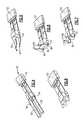
- FIG. 5is a perspective view of the example lead frame prior to insulation attachment to a wire.
- FIG. 6is a perspective view of the lead frame including a piercing end that is bent in an initial manner.
- FIG. 7is another perspective view of an example lead frame where each of the lead frames is bent in a final manner.
- FIG. 8is a perspective view of the example lead frame with the lead frames bent into the final configuration with the wire removed for clarity purposes.
- FIGS. 9A-9Fare side views of the example steps performed to attach a wire to the example lead frame.
- FIG. 10is a perspective view of another wire lead frame connection.
- FIG. 11is a perspective view of a bottom portion of the example lead frame connection.
- FIG. 12is a cross-sectional view of the example clip installed to the lead frame and inserted into the example wire.
- FIG. 13is a perspective view of an example clip for attaching and electrically communicating a wire to a lead frame.
- FIG. 14is a plan view of the example clip prior to bending.
- FIG. 15is a perspective view of a portion of the lead frame configured to receive the example clip.
- FIG. 16is an enlarged view of the area of the lead frame configured to receive the example clip.
- FIG. 17is another example lead frame including crimped portions disposed on each lead frame.
- FIG. 18is an example lead frame including the crimped portions formed in a pre-crimped manner.
- FIG. 19is a perspective view illustrating wire connections to the crimped portions.
- an integrated circuit assembly 10includes an integrated circuit 16 encapsulated to protect the circuit components therein. Extending outwardly from the encapsulated integrated circuit 16 is a first lead frame 12 and a second lead frame 14 .
- the first and second lead frames 12 , 14are for attachment to an electrical conduit to provide electrical communication to the circuit assembly 16 .
- Each of the first and second lead frames 12 , 14include corresponding piercing ends 18 , 20 .
- the piercing ends 18 , 20comprise a point that provides a sharp edge for insertion into a perpendicular face of an electrical conduit such as wires within a cable jacket.
- the example piercing ends 18 , 20are formed at a terminal end of angled sides 22 , 24 .
- the angled sides 22 , 24taper from a greatest width of the corresponding lead frame 12 , 14 to the ends 18 , 20 .
- the piercing ends 18 , 20are intended for insertion into a perpendicular face of a wire such as for example the wires 34 , 36 that are assembled within a cable jacket 28 .
- the wires 34 , 36are disposed adjacent each other and include in insulation layer 34 , 38 .
- the insulation layer 34 , 38surrounds each of the wires and provides a separation of electrical communication between the two wires 34 , 36 .
- the piercing ends 18 , 20are inserted into the wire face to provide the desired electrical communication between each of the wires and the circuit assembly 16 .
- the example angled side portions 22 , 24can include serrated edges 26 to inhibit removal of the circuit assembly 10 once installed within the desired corresponding wire.
- the example integrated circuit 10includes the piercing ends 18 , 20 on corresponding first and second leads 12 and 14 to allow for the simple insertion and electrical connection between separate electrical conductors such as the wires 36 and 34 .
- This electrical connectionis provided without the use of other processes such as welding, soldering, and further does not require stripping and removal of the insulation layers 34 , 38 . All that is required is that the face of the cable 28 be prepared to receive the piercing ends 18 , 20 . Once the circuit assembly 10 is inserted into the desired cable assembly 28 , the entire cable assembly along with the circuit can be overmolded.
- FIG. 4another example circuit assembly 50 is shown and includes an overmolded integrated circuit 52 and first and second leads 54 , 56 .
- the leads 54 , 56extend from the integrated circuit 52 and include a portion for receiving and mechanically holding electrical wires 58 , 60 .
- the leads 54 , 56are selectively bent to provide a piercing function through the insulation of each of the wires 58 , 60 .
- the piercing connection processdoes not require stripping of insulation from the wires 58 , 60 .
- the leads 54 , 56extend through the insulation and into the electric conductive material of the wires 58 , 60 to provide the desired electrical contact.
- the leads 54 , 56are also selectively bent to mechanically fasten the circuit assembly 52 to the accompanying wires 58 , 60 .
- the first and second leads 54 and 56include piercing edges 64 .
- the piercing edges 64include a point that is provided by an angled surface that tapers from one side of each of the leads 54 , 56 to the other. This tapered edge forms the piercing points utilized to extend through any insulation in the wires 58 , 60 .
- FIG. 5illustrates the leads 54 , 56 in an initial manner where the piercing edges 64 have been formed.
- the piercing edges 64are bent upwardly within a first initial bend 66 .
- This initial bend 66points the piercing edge 64 upwardly in a perpendicular manner relative to the initial position of the leads 54 , 56 .
- This upward extensionis the initial bend utilized to position the piercing edge 64 to receive the wires 58 , 60 .
- the upwardly bent portions of the first and second leads 54 , 56are then twisted such that the piercing edges 64 are disposed longitudinally relative to each of the first and second lead 54 , 56 .
- the twist bendingpositions the piercing point 64 and the tapered surface that is utilized to form that point in a longitudinal direction parallel with the direction of each of the wires 58 , 60 .
- the ends of each of the leads 54 , 56are disposed to point perpendicularly upward from each of the lead frames 54 , 56 such that the piercing edges 64 extend upward with the tapered edge portion positioned longitudinally.
- Each of the wiresis then inserted beginning at the piercing edge 64 downwardly onto the corresponding lead 54 , 56 .
- the downward forcedrives the piercing edge 64 through the wire such that a portion of the corresponding lead 54 , 56 extends entirely through the corresponding electrical conduit.
- the portion of the lead 54 , 56 that extends entirely through the corresponding electrical wires 58 , 60is then utilized to mechanically attach the wire in place. This mechanical attachment is provided by bending of the exposed portion of the lead around the wire.
- the final bendis illustrated without the electrical wire to show the piercing edge 64 wrapped around the wires 58 , 60 .
- the wiresare removed to provide a clear view of the bending orientation of the corresponding leads.
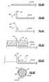
- FIGS. 9A-9Fexample bending and assembly steps are schematically illustrated.
- the piercing edge 64is formed by tapering an edge surface of the corresponding conduit.
- the piercing edge 64is then bent upwardly through an initial bend 68 .
- This initial bend 68positions the piercing edge 64 to extend transversely or perpendicular to the remainder of the corresponding lead frame 54 , 56 .
- the upward extending portion of the lead frame 54 , 56 including the piercing edge 64is then twisted by rotating it clockwise or counter-clockwise to position the tapered surface and piercing edge 64 longitudinally along the same direction as the lead frames.
- This twisting bendplaces the tapered portion and piercing edge 64 in a longitudinal orientation substantially centered along each of the corresponding lead frames 54 , 56 .
- the lead frames 54 , 56are prepared to receive a wire for the connection and electrical attachment to the corresponding lead frame 54 , 56 .
- a wire 58 , 60is inserted over the upwardly extending portion of the lead frame 54 , 56 such that the piercing edge 64 extends entirely through the corresponding wire conduit 58 , 60 .
- the insulation 62 for each wire 58 , 60is left on as the piercing edge 64 extends not only through the insulation but through the electrical conductive material.
- the piercing edge 64along with a portion of the upward extending through part of the lead frame 54 , 56 extends upwardly above the corresponding wire 58 , 60 to provide material for mechanically attaching and securing the wire 58 , 60 to the lead frame 54 , 56 .
- the upward extending portion 72is bent downwardly over and around the wire 58 , 60 along a bend 70 .
- This wrapping of the portion 72provides a mechanical attachment required to secure the wires 58 and 60 to the lead frame 54 , 56 .
- a cross-sectional view of the completed connectionis shown that includes the lead frame 54 , 56 along with the upward extended portion 72 that is wrapped around the corresponding wire 58 , 60 .
- the portion 72wraps only about one portion of the wire 58 , 60 to trap and mechanically secure the wire 58 , 60 .
- the length of the wrap around portion 72can be modified to overlap the wire 58 , 60 to provide more or less mechanical attachment as is desired.
- another example attachment assembly 80includes a clip 88 that is attached to a corresponding one of the lead frames 84 , 86 extending from an encapsulated circuit assembly 82 .
- the clip 88is inserted through conductive material of the wire 90 and clamped to the corresponding one of the lead frames 84 , 86 .
- a piercing portion 96 of the clip 88extends through the wire insulation 94 into the electrically conductive material 92 .
- the clip 88is then secured to a portion of the corresponding lead frame 84 .
- the clip 88includes clamp portions along with the piercing portion 96 that is inserted through the insulation 94 and into the electrical conductive material 92 of the wire 90 .
- Another clamp portionsupports the piercing portion 96 and wraps about the corresponding lead frame 84 , 86 .
- the clip 88includes legs 98 , 100 , 102 .
- the legs 98 , 100 , and 102are selectively bent from a flat sheet of material illustrated in FIG. 14 .
- the clip 88begins as a flat sheet of material with the legs 98 , 100 , 102 .
- the legs 98 , 100 , 102are bent along bend lines 104 , 106 , and 108 to provide the desired configuration of the clip assembly 88 .
- the clip assembly 88includes the piercing surface 96 that pierces through the wire insulation and into the electrical conductor 92 .
- the example integrated circuit assembly 82includes the leads 116 and 114 .
- the leads 116 and 114include a specific surface designed to engage a portion of the example clip 88 .
- the surface 110includes a plurality of teeth 112 .
- the teeth 112extend from a planar surface to provide a rough edge. This edge is locked into securing legs 98 , 100 , 102 of the clip 88 to provide a desired interference fit that aids in maintaining the clip 88 on the corresponding one of the lead frames 116 , 114 .
- another example integrated circuit assembly 140includes an integrated circuit 142 overmolded with leads 144 and 146 extending there from.
- Each of the leads 144 and 146include corresponding crimp pads 148 and 150 .
- Each of the crimped padsis offset from each other to prevent a short between the corresponding leads 144 , 146 .
- the crimp pads 148 and 150include a larger width and additional material than the remainder of the corresponding leads 144 , 146 .
- the example pads 148 and 150are crimped onto each other to form crimp configurations 150 , 152 .
- FIG. 18showed the finish crimp without electrical conduits 158 , 160 for clarity.
- the electrical conduit 158 , 160is inserted into the opening provided by the rolled over portions of the crimp configurations 150 , 152 .
- FIG. 19shows the wires 158 , 160 inserted into the corresponding crimp configurations 150 , 152 , with the crimp pressed inwardly to engage and secure the wire to the leads 144 , 146 .
- the example integrated circuit lead frame assemblies disclosed in this applicationprovide different mechanical means of both securing and providing the desired electrical connection without requiring additional processes such as welding and soldering. Further, several of the disclosed examples electrical connection without removal of any corresponding insulation.
Landscapes
- Coupling Device And Connection With Printed Circuit (AREA)
Abstract
Description
Claims (19)
Priority Applications (1)
| Application Number | Priority Date | Filing Date | Title |
|---|---|---|---|
| US11/939,070US7837494B2 (en) | 2007-02-26 | 2007-11-13 | Connection of wire to a lead frame |
Applications Claiming Priority (3)
| Application Number | Priority Date | Filing Date | Title |
|---|---|---|---|
| US89160907P | 2007-02-26 | 2007-02-26 | |
| US89159707P | 2007-02-26 | 2007-02-26 | |
| US11/939,070US7837494B2 (en) | 2007-02-26 | 2007-11-13 | Connection of wire to a lead frame |
Publications (2)
| Publication Number | Publication Date |
|---|---|
| US20080205020A1 US20080205020A1 (en) | 2008-08-28 |
| US7837494B2true US7837494B2 (en) | 2010-11-23 |
Family
ID=39715649
Family Applications (1)
| Application Number | Title | Priority Date | Filing Date |
|---|---|---|---|
| US11/939,070Expired - Fee RelatedUS7837494B2 (en) | 2007-02-26 | 2007-11-13 | Connection of wire to a lead frame |
Country Status (1)
| Country | Link |
|---|---|
| US (1) | US7837494B2 (en) |
Cited By (10)
| Publication number | Priority date | Publication date | Assignee | Title |
|---|---|---|---|---|
| US20110130045A1 (en)* | 2009-12-01 | 2011-06-02 | Hon Hai Precision Industry Co., Ltd. | Electrical connector assembly and method for making the same |
| US20110250797A1 (en)* | 2010-04-07 | 2011-10-13 | Hon Hai Precision Industry Co., Ltd. | Cable assembly with improved terminating means |
| US20110250796A1 (en)* | 2010-04-07 | 2011-10-13 | Hon Hai Precision Industry Co., Ltd. | Cable assembly with improved terminating means |
| US20110281458A1 (en)* | 2010-05-12 | 2011-11-17 | Hon Hai Precision Industry Co., Ltd. | Cable assembly with improved terminating means |
| US9142924B2 (en) | 2012-08-23 | 2015-09-22 | Zierick Manufacturing Corp. | Surface mount coaxial cable connector |
| US9229029B2 (en) | 2011-11-29 | 2016-01-05 | Formfactor, Inc. | Hybrid electrical contactor |
| US10222037B2 (en) | 2013-09-13 | 2019-03-05 | Willis Electric Co., Ltd. | Decorative lighting with reinforced wiring |
| US10700480B2 (en)* | 2017-12-06 | 2020-06-30 | Raydiall | Electrical impedance matching part for connector mounted on cable with insulated electrical wires |
| US10718475B2 (en) | 2013-09-13 | 2020-07-21 | Willis Electric Co., Ltd. | Tangle-resistant decorative lighting assembly |
| US11306881B2 (en) | 2013-09-13 | 2022-04-19 | Willis Electric Co., Ltd. | Tangle-resistant decorative lighting assembly |
Families Citing this family (21)
| Publication number | Priority date | Publication date | Assignee | Title |
|---|---|---|---|---|
| US8853721B2 (en) | 2010-03-05 | 2014-10-07 | Willis Electric Co., Ltd. | Light-emitting diode with wire-piercing lead frame |
| US8568015B2 (en) | 2010-09-23 | 2013-10-29 | Willis Electric Co., Ltd. | Decorative light string for artificial lighted tree |
| US8298633B1 (en) | 2011-05-20 | 2012-10-30 | Willis Electric Co., Ltd. | Multi-positional, locking artificial tree trunk |
| US8920002B2 (en) | 2011-06-21 | 2014-12-30 | Willis Electric Co., Ltd. | Wire-clasping light-emitting diode lights |
| US8469750B2 (en) | 2011-09-22 | 2013-06-25 | Willis Electric Co., Ltd. | LED lamp assembly and light strings including a lamp assembly |
| US9157587B2 (en) | 2011-11-14 | 2015-10-13 | Willis Electric Co., Ltd. | Conformal power adapter for lighted artificial tree |
| US8569960B2 (en) | 2011-11-14 | 2013-10-29 | Willis Electric Co., Ltd | Conformal power adapter for lighted artificial tree |
| US8876321B2 (en) | 2011-12-09 | 2014-11-04 | Willis Electric Co., Ltd. | Modular lighted artificial tree |
| US9044056B2 (en) | 2012-05-08 | 2015-06-02 | Willis Electric Co., Ltd. | Modular tree with electrical connector |
| US9179793B2 (en) | 2012-05-08 | 2015-11-10 | Willis Electric Co., Ltd. | Modular tree with rotation-lock electrical connectors |
| US9572446B2 (en) | 2012-05-08 | 2017-02-21 | Willis Electric Co., Ltd. | Modular tree with locking trunk and locking electrical connectors |
| US10206530B2 (en) | 2012-05-08 | 2019-02-19 | Willis Electric Co., Ltd. | Modular tree with locking trunk |
| US10229785B2 (en)* | 2012-12-06 | 2019-03-12 | Kemet Electronics Corporation | Multi-layered ceramic capacitor with soft leaded module |
| US9439528B2 (en) | 2013-03-13 | 2016-09-13 | Willis Electric Co., Ltd. | Modular tree with locking trunk and locking electrical connectors |
| US9671074B2 (en) | 2013-03-13 | 2017-06-06 | Willis Electric Co., Ltd. | Modular tree with trunk connectors |
| US9157588B2 (en) | 2013-09-13 | 2015-10-13 | Willis Electric Co., Ltd | Decorative lighting with reinforced wiring |
| US9894949B1 (en) | 2013-11-27 | 2018-02-20 | Willis Electric Co., Ltd. | Lighted artificial tree with improved electrical connections |
| US8870404B1 (en) | 2013-12-03 | 2014-10-28 | Willis Electric Co., Ltd. | Dual-voltage lighted artificial tree |
| US9883566B1 (en) | 2014-05-01 | 2018-01-30 | Willis Electric Co., Ltd. | Control of modular lighted artificial trees |
| USD823256S1 (en)* | 2017-02-15 | 2018-07-17 | Izzy Industries Inc. | Grounding strap head |
| US10683974B1 (en) | 2017-12-11 | 2020-06-16 | Willis Electric Co., Ltd. | Decorative lighting control |
Citations (18)
| Publication number | Priority date | Publication date | Assignee | Title |
|---|---|---|---|---|
| US1117650A (en)* | 1913-12-30 | 1914-11-17 | Eugene I Rosenfeld & Co Inc | Detachable lamp-socket. |
| US2799841A (en)* | 1951-06-16 | 1957-07-16 | Amp Inc | Electrical connector and method of its manufacture and use |
| US3631298A (en)* | 1969-10-24 | 1971-12-28 | Bunker Ramo | Woven interconnection structure |
| US3715457A (en)* | 1970-06-30 | 1973-02-06 | Amp Inc | Two piece flat cable connector |
| US3934075A (en)* | 1974-02-26 | 1976-01-20 | E. I. Du Pont De Nemours And Company | Clip for shielded multiconductor flat cable |
| US4018499A (en)* | 1973-12-18 | 1977-04-19 | Amp Incorporated | Contact for insulated wire |
| US4971564A (en)* | 1988-04-15 | 1990-11-20 | Ferdie Meyer | Method and article used for connecting electronic components |
| US5044071A (en)* | 1989-04-03 | 1991-09-03 | Murata Manufacturing Co., Ltd. | Manufacturing method for taping electronic component |
| US5133673A (en)* | 1990-04-18 | 1992-07-28 | E. I. Du Pont De Nemours And Company | Connecting element |
| US5196374A (en)* | 1990-01-26 | 1993-03-23 | Sgs-Thomson Microelectronics, Inc. | Integrated circuit package with molded cell |
| US5318458A (en)* | 1991-01-11 | 1994-06-07 | Thoerner Wolfgang B | Device for connecting to the end of a cable |
| US5656847A (en)* | 1994-02-28 | 1997-08-12 | Rohm Co., Ltd. | Led lamp arrangement and led matrix display panel |
| US6017241A (en)* | 1998-01-26 | 2000-01-25 | Tivoli Industries, Inc. | Aisle lighting lampholder |
| US6350146B1 (en)* | 2000-04-25 | 2002-02-26 | Hon Hai Precision Ind. Co, Ltd. | Cable connector assembly |
| US6350145B1 (en)* | 1999-03-11 | 2002-02-26 | Japan Solderless Terminal Mfg. Co., Ltd. | Flexible printed circuit board crimp terminal and crimping structure for core therewith |
| US6726502B1 (en)* | 2003-03-21 | 2004-04-27 | Fci Americas Technology Inc. | LED and flex cable lighting assembly |
| US7217012B2 (en)* | 2001-05-25 | 2007-05-15 | Lumination, Llc | Illuminated signage employing light emitting diodes |
| US7442070B2 (en)* | 2007-02-15 | 2008-10-28 | Super Link Electronics Co., Ltd. | Light-emitting cell module |
- 2007
- 2007-11-13USUS11/939,070patent/US7837494B2/ennot_activeExpired - Fee Related
Patent Citations (18)
| Publication number | Priority date | Publication date | Assignee | Title |
|---|---|---|---|---|
| US1117650A (en)* | 1913-12-30 | 1914-11-17 | Eugene I Rosenfeld & Co Inc | Detachable lamp-socket. |
| US2799841A (en)* | 1951-06-16 | 1957-07-16 | Amp Inc | Electrical connector and method of its manufacture and use |
| US3631298A (en)* | 1969-10-24 | 1971-12-28 | Bunker Ramo | Woven interconnection structure |
| US3715457A (en)* | 1970-06-30 | 1973-02-06 | Amp Inc | Two piece flat cable connector |
| US4018499A (en)* | 1973-12-18 | 1977-04-19 | Amp Incorporated | Contact for insulated wire |
| US3934075A (en)* | 1974-02-26 | 1976-01-20 | E. I. Du Pont De Nemours And Company | Clip for shielded multiconductor flat cable |
| US4971564A (en)* | 1988-04-15 | 1990-11-20 | Ferdie Meyer | Method and article used for connecting electronic components |
| US5044071A (en)* | 1989-04-03 | 1991-09-03 | Murata Manufacturing Co., Ltd. | Manufacturing method for taping electronic component |
| US5196374A (en)* | 1990-01-26 | 1993-03-23 | Sgs-Thomson Microelectronics, Inc. | Integrated circuit package with molded cell |
| US5133673A (en)* | 1990-04-18 | 1992-07-28 | E. I. Du Pont De Nemours And Company | Connecting element |
| US5318458A (en)* | 1991-01-11 | 1994-06-07 | Thoerner Wolfgang B | Device for connecting to the end of a cable |
| US5656847A (en)* | 1994-02-28 | 1997-08-12 | Rohm Co., Ltd. | Led lamp arrangement and led matrix display panel |
| US6017241A (en)* | 1998-01-26 | 2000-01-25 | Tivoli Industries, Inc. | Aisle lighting lampholder |
| US6350145B1 (en)* | 1999-03-11 | 2002-02-26 | Japan Solderless Terminal Mfg. Co., Ltd. | Flexible printed circuit board crimp terminal and crimping structure for core therewith |
| US6350146B1 (en)* | 2000-04-25 | 2002-02-26 | Hon Hai Precision Ind. Co, Ltd. | Cable connector assembly |
| US7217012B2 (en)* | 2001-05-25 | 2007-05-15 | Lumination, Llc | Illuminated signage employing light emitting diodes |
| US6726502B1 (en)* | 2003-03-21 | 2004-04-27 | Fci Americas Technology Inc. | LED and flex cable lighting assembly |
| US7442070B2 (en)* | 2007-02-15 | 2008-10-28 | Super Link Electronics Co., Ltd. | Light-emitting cell module |
Cited By (10)
| Publication number | Priority date | Publication date | Assignee | Title |
|---|---|---|---|---|
| US20110130045A1 (en)* | 2009-12-01 | 2011-06-02 | Hon Hai Precision Industry Co., Ltd. | Electrical connector assembly and method for making the same |
| US20110250797A1 (en)* | 2010-04-07 | 2011-10-13 | Hon Hai Precision Industry Co., Ltd. | Cable assembly with improved terminating means |
| US20110250796A1 (en)* | 2010-04-07 | 2011-10-13 | Hon Hai Precision Industry Co., Ltd. | Cable assembly with improved terminating means |
| US20110281458A1 (en)* | 2010-05-12 | 2011-11-17 | Hon Hai Precision Industry Co., Ltd. | Cable assembly with improved terminating means |
| US9229029B2 (en) | 2011-11-29 | 2016-01-05 | Formfactor, Inc. | Hybrid electrical contactor |
| US9142924B2 (en) | 2012-08-23 | 2015-09-22 | Zierick Manufacturing Corp. | Surface mount coaxial cable connector |
| US10222037B2 (en) | 2013-09-13 | 2019-03-05 | Willis Electric Co., Ltd. | Decorative lighting with reinforced wiring |
| US10718475B2 (en) | 2013-09-13 | 2020-07-21 | Willis Electric Co., Ltd. | Tangle-resistant decorative lighting assembly |
| US11306881B2 (en) | 2013-09-13 | 2022-04-19 | Willis Electric Co., Ltd. | Tangle-resistant decorative lighting assembly |
| US10700480B2 (en)* | 2017-12-06 | 2020-06-30 | Raydiall | Electrical impedance matching part for connector mounted on cable with insulated electrical wires |
Also Published As
| Publication number | Publication date |
|---|---|
| US20080205020A1 (en) | 2008-08-28 |
Similar Documents
| Publication | Publication Date | Title |
|---|---|---|
| US7837494B2 (en) | Connection of wire to a lead frame | |
| US9711872B2 (en) | Crimp terminal and structure for connecting crimp terminal and wire | |
| JP6060015B2 (en) | Crimp structure for the wire of the crimp terminal | |
| US8951063B2 (en) | Crimp terminal | |
| US7121903B2 (en) | Terminal | |
| JP2009129812A (en) | Joint structure and joint method of copper wire and aluminum wire | |
| EP2675019A1 (en) | Ground terminal assembly structure and corresponding method | |
| KR20120045064A (en) | Wire holder | |
| US9236667B2 (en) | Connection structure | |
| US9368953B2 (en) | Terminal-formed wire and manufacturing method thereof | |
| CN105390905B (en) | Cover the joint method of skin electric wire | |
| US9270039B2 (en) | Surface mount connector for electrically isolating two insulated conductors | |
| WO2013039124A1 (en) | Structure of connection between coaxial cable and shield terminal, and method of connection therebetween | |
| JP5376639B2 (en) | Crimp terminal structure and harness | |
| US10181658B2 (en) | Electric machine with electrical connector | |
| JPH087968A (en) | Connector and assembly method thereof | |
| JP5520627B2 (en) | Connection structure | |
| JPH088034A (en) | Assembly method of flat cable connector | |
| WO2014200069A1 (en) | Flat-cable connection structure | |
| KR102716222B1 (en) | Joint terminal for wire of vehicle | |
| US20030217861A1 (en) | Insulated wire splice | |
| JP2001185248A (en) | Crimp joint connector | |
| JP6282818B2 (en) | Pressure contact connector and wire pressure contact connector | |
| JPH0121493Y2 (en) | ||
| JP2014164848A (en) | Crimp terminal, crimp connection structure, connector, and crimping method of crimp terminal |
Legal Events
| Date | Code | Title | Description |
|---|---|---|---|
| AS | Assignment | Owner name:SIEMENS VDO AUTOMOTIVE CORPORATION, MICHIGAN Free format text:ASSIGNMENT OF ASSIGNORS INTEREST;ASSIGNOR:VICH, GAETAN;REEL/FRAME:020102/0442 Effective date:20071112 Owner name:SIEMENS VDO AUTOMOTIVE CORPORATION,MICHIGAN Free format text:ASSIGNMENT OF ASSIGNORS INTEREST;ASSIGNOR:VICH, GAETAN;REEL/FRAME:020102/0442 Effective date:20071112 | |
| FEPP | Fee payment procedure | Free format text:PAYER NUMBER DE-ASSIGNED (ORIGINAL EVENT CODE: RMPN); ENTITY STATUS OF PATENT OWNER: LARGE ENTITY Free format text:PAYOR NUMBER ASSIGNED (ORIGINAL EVENT CODE: ASPN); ENTITY STATUS OF PATENT OWNER: LARGE ENTITY | |
| AS | Assignment | Owner name:CONTINENTAL AUTOMTOIVE SYSTEMS US, INC., MICHIGAN Free format text:CHANGE OF NAME;ASSIGNOR:SIEMENS VDO AUTOMOTIVE CORPORATION;REEL/FRAME:025163/0745 Effective date:20071203 | |
| STCF | Information on status: patent grant | Free format text:PATENTED CASE | |
| FPAY | Fee payment | Year of fee payment:4 | |
| AS | Assignment | Owner name:CONTINENTAL AUTOMOTIVE SYSTEMS, INC., MICHIGAN Free format text:MERGER;ASSIGNOR:CONTINENTAL AUTOMOTIVE SYSTEMS US, INC.;REEL/FRAME:033034/0225 Effective date:20121212 | |
| MAFP | Maintenance fee payment | Free format text:PAYMENT OF MAINTENANCE FEE, 8TH YEAR, LARGE ENTITY (ORIGINAL EVENT CODE: M1552) Year of fee payment:8 | |
| FEPP | Fee payment procedure | Free format text:MAINTENANCE FEE REMINDER MAILED (ORIGINAL EVENT CODE: REM.); ENTITY STATUS OF PATENT OWNER: LARGE ENTITY | |
| LAPS | Lapse for failure to pay maintenance fees | Free format text:PATENT EXPIRED FOR FAILURE TO PAY MAINTENANCE FEES (ORIGINAL EVENT CODE: EXP.); ENTITY STATUS OF PATENT OWNER: LARGE ENTITY | |
| STCH | Information on status: patent discontinuation | Free format text:PATENT EXPIRED DUE TO NONPAYMENT OF MAINTENANCE FEES UNDER 37 CFR 1.362 | |
| FP | Lapsed due to failure to pay maintenance fee | Effective date:20221123 |