US7837349B2 - Near field lens - Google Patents
Near field lensDownload PDFInfo
- Publication number
- US7837349B2 US7837349B2US11/763,884US76388407AUS7837349B2US 7837349 B2US7837349 B2US 7837349B2US 76388407 AUS76388407 AUS 76388407AUS 7837349 B2US7837349 B2US 7837349B2
- Authority
- US
- United States
- Prior art keywords
- light
- lens
- main body
- face
- central axis
- Prior art date
- Legal status (The legal status is an assumption and is not a legal conclusion. Google has not performed a legal analysis and makes no representation as to the accuracy of the status listed.)
- Active, expires
Links
Images


Classifications
- G—PHYSICS
- G02—OPTICS
- G02B—OPTICAL ELEMENTS, SYSTEMS OR APPARATUS
- G02B19/00—Condensers, e.g. light collectors or similar non-imaging optics
- G02B19/0033—Condensers, e.g. light collectors or similar non-imaging optics characterised by the use
- G02B19/0047—Condensers, e.g. light collectors or similar non-imaging optics characterised by the use for use with a light source
- G02B19/0061—Condensers, e.g. light collectors or similar non-imaging optics characterised by the use for use with a light source the light source comprising a LED
- F—MECHANICAL ENGINEERING; LIGHTING; HEATING; WEAPONS; BLASTING
- F21—LIGHTING
- F21S—NON-PORTABLE LIGHTING DEVICES; SYSTEMS THEREOF; VEHICLE LIGHTING DEVICES SPECIALLY ADAPTED FOR VEHICLE EXTERIORS
- F21S41/00—Illuminating devices specially adapted for vehicle exteriors, e.g. headlamps
- F21S41/30—Illuminating devices specially adapted for vehicle exteriors, e.g. headlamps characterised by reflectors
- F21S41/32—Optical layout thereof
- F21S41/322—Optical layout thereof the reflector using total internal reflection
- F—MECHANICAL ENGINEERING; LIGHTING; HEATING; WEAPONS; BLASTING
- F21—LIGHTING
- F21S—NON-PORTABLE LIGHTING DEVICES; SYSTEMS THEREOF; VEHICLE LIGHTING DEVICES SPECIALLY ADAPTED FOR VEHICLE EXTERIORS
- F21S43/00—Signalling devices specially adapted for vehicle exteriors, e.g. brake lamps, direction indicator lights or reversing lights
- F21S43/10—Signalling devices specially adapted for vehicle exteriors, e.g. brake lamps, direction indicator lights or reversing lights characterised by the light source
- F21S43/13—Signalling devices specially adapted for vehicle exteriors, e.g. brake lamps, direction indicator lights or reversing lights characterised by the light source characterised by the type of light source
- F21S43/14—Light emitting diodes [LED]
- F—MECHANICAL ENGINEERING; LIGHTING; HEATING; WEAPONS; BLASTING
- F21—LIGHTING
- F21S—NON-PORTABLE LIGHTING DEVICES; SYSTEMS THEREOF; VEHICLE LIGHTING DEVICES SPECIALLY ADAPTED FOR VEHICLE EXTERIORS
- F21S43/00—Signalling devices specially adapted for vehicle exteriors, e.g. brake lamps, direction indicator lights or reversing lights
- F21S43/30—Signalling devices specially adapted for vehicle exteriors, e.g. brake lamps, direction indicator lights or reversing lights characterised by reflectors
- F21S43/31—Optical layout thereof
- F21S43/315—Optical layout thereof using total internal reflection
- F—MECHANICAL ENGINEERING; LIGHTING; HEATING; WEAPONS; BLASTING
- F21—LIGHTING
- F21V—FUNCTIONAL FEATURES OR DETAILS OF LIGHTING DEVICES OR SYSTEMS THEREOF; STRUCTURAL COMBINATIONS OF LIGHTING DEVICES WITH OTHER ARTICLES, NOT OTHERWISE PROVIDED FOR
- F21V5/00—Refractors for light sources
- F21V5/04—Refractors for light sources of lens shape
- F—MECHANICAL ENGINEERING; LIGHTING; HEATING; WEAPONS; BLASTING
- F21—LIGHTING
- F21V—FUNCTIONAL FEATURES OR DETAILS OF LIGHTING DEVICES OR SYSTEMS THEREOF; STRUCTURAL COMBINATIONS OF LIGHTING DEVICES WITH OTHER ARTICLES, NOT OTHERWISE PROVIDED FOR
- F21V7/00—Reflectors for light sources
- F21V7/0091—Reflectors for light sources using total internal reflection
- G—PHYSICS
- G02—OPTICS
- G02B—OPTICAL ELEMENTS, SYSTEMS OR APPARATUS
- G02B19/00—Condensers, e.g. light collectors or similar non-imaging optics
- G02B19/0004—Condensers, e.g. light collectors or similar non-imaging optics characterised by the optical means employed
- G02B19/0028—Condensers, e.g. light collectors or similar non-imaging optics characterised by the optical means employed refractive and reflective surfaces, e.g. non-imaging catadioptric systems
- F—MECHANICAL ENGINEERING; LIGHTING; HEATING; WEAPONS; BLASTING
- F21—LIGHTING
- F21Y—INDEXING SCHEME ASSOCIATED WITH SUBCLASSES F21K, F21L, F21S and F21V, RELATING TO THE FORM OR THE KIND OF THE LIGHT SOURCES OR OF THE COLOUR OF THE LIGHT EMITTED
- F21Y2115/00—Light-generating elements of semiconductor light sources
- F21Y2115/10—Light-emitting diodes [LED]
Definitions
- the present inventiongenerally relates to lighting systems. More particularly, the present invention relates to lighting systems that employ lenses to collect light from a light source and direct the light within the lighting system.
- a single light-emitting diodedoes not provide enough light intensity to meet the light intensity requirements of the application. Therefore, multiple LEDs are used.
- a plurality of low-powered LEDsten or more for example, each with its own dedicated reflector or lens optics, are used in many automotive lighting applications.
- Each LEDtypically has its own near field lens (NFL) to provide efficient light collection and distribution within the vehicle lighting system.
- NNLnear field lens
- each LEDmust be placed at the focal point of the NFL.
- NFLstypically have focal points located along a single center axis, and therefore, the LED must be located along this center axis.
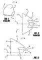
- FIGS. 1 and 2a typical NFL 10 is illustrated.
- the NFL 10is a surface of revolution, rotated about axis X.
- the top half 16 of the cross section of the NFL 10is rotated about the axis X, such that the NFL is radially symmetrical about the axis X.
- the NFL 10also has an optical axis that is coincident with the axis X.
- the optical axis Xincludes a focal point F of the NFL 10 .
- the NFL 10Since the NFL 10 has one focal point F, it is designed for use with a single LED positioned at the focal point F.
- the NFL 10itself includes a light-collecting face 11 , a light-emitting face 12 , and a side surface 13 .
- the light-collecting face 11is further comprised of an axial surface 14 surrounded by a radial surface 15 .
- the present inventionprovides a lens assembly that is compact, while providing the requisite light intensity.
- the lens assembly of the inventionuses multiple LEDs with a single lens or NFL. To accomplish this, the lens has a plurality of focal points forming a focal ring, rather than a single focal point. Multiple LEDs or other light sources are positioned along the focal ring, providing for much brighter light intensity than would be available using a single light source.
- a lens having a main body for use with a plurality of light sourcesis provided.
- the main body of the lensis substantially radially symmetrical about an axis of revolution, which extends through a light-collecting face and a light-emitting face.
- the lensdefines a plurality of focal points, and the focal points form a focal ring surrounding the axis.
- the lensis incorporated into a light assembly having a plurality of light sources.
- the light sourcesare positioned coincident with the focal ring.
- FIG. 1is a perspective view of a prior art lens
- FIG. 2is a cross-sectional view of the prior art lens of FIG. 1 ;
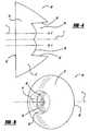
- FIG. 3is a schematic partial cross-sectional view of a lens embodying the principles of the present invention.
- FIG. 4is a schematic full cross-sectional view of the lens of FIG. 3 ;
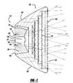
- FIG. 5is a perspective view of the lens of FIGS. 3-4 ;
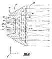
- FIG. 6is a schematic side view of the lens of FIGS. 3-5 , having light rays being directed therethrough;
- FIG. 7is a schematic side view of another lens embodying the principles of the present invention, showing light rays being directed therethrough;
- FIG. 8is a schematic side view of yet another lens embodying the principles of the present invention, having light rays being directed therethrough.
- the present inventiongenerally provides a near field lens 20 for use with multiple light sources, preferably LEDs. Because multiple LEDs may be used with a single near field lens 20 embodying the principles of the present invention, the size and complexity of a lighting system may be reduced.
- the lens 20is a surface of revolution about an axis of revolution X and includes a main body 21 .
- the main body 21includes a light-emitting face 22 disposed opposite a light-collecting face 24 .
- the light-collecting face 24further has an axial surface 26 surrounded by a radial surface 28 , wherein the surfaces 26 , 28 define a pocket 30 in the lens 20 ; however, it is contemplated that the light-collecting face 24 could have other configurations without falling beyond the spirit and scope of the present invention.
- the axis of revolution Xextends through the light-emitting face 22 and the light-collecting face 24 .
- the top half 18 of the cross section of the lens 20has an optical axis Y, containing focal point F, that extends through the light-emitting face 22 and axial surface 26 of the light-collecting face 24 .
- the focal point Fis the location at which a light source can emanate light rays and the light rays will be refracted through the light-collecting face 24 , reflected through the lens 20 and transmitted through the light-emitting face 22 in a substantially collimated manner.
- the optical axis Yis not coincident with the axis of revolution X. Rather, the optical axis Y is parallel to and spaced apart, or offset, from the axis of revolution X.
- the optical axis YWhen the top half 18 of the cross section of the lens 20 is rotated about the axis of a revolution X, the optical axis Y will also be rotated around the axis of revolution X and will form a cylindrical pattern of an infinite number of optical axes Y. Similarly, the focal point F will also be rotated around the axis of revolution X forming a circular pattern of an infinite number of focal points F, which is hereinafter referred to as a focal ring 31 that surrounds the axis of revolution X.
- the lensmay be constructed of any suitable material, such as glass, the lens 20 is preferably constructed of an optical grade thermoplastic material.
- a light assembly 32 incorporating the previously described lens 20 and a plurality of light sources 34are schematically illustrated therein.
- the light sources 34are positioned adjacent to the light-collecting face 24 along the focal ring 31 .
- two light sources 34are shown as being located at the upper and lower focal points F in this figure.
- the light assembly 32would include multiple light sources 32 at various other positions along the focal ring 31 , generally in a circular pattern.
- the light rays 36 produced by the light sources 34are best captured by the lens 20 when the light sources 34 are located along the optical axes Y, at the focal points F along the focal ring 31 .
- some of the light rays 36 emitted from the light sources 34are transmitted through the axial surface 26 . These light rays 36 are refracted through the axially-facing surface 26 of the lens 20 in a mostly collimated manner. The light rays 36 then continue through the lens 20 and are emitted from the lens 20 by the light-emitting face 22 .
- TIRtotal internal reflection
- the light rays 36are reflected by the side surface 38 in a collimated manner toward the light-emitting face 22 ; however, it is contemplated that the side surface 38 could reflect the light rays 36 without collimating them, while still being within the spirit and scope of the present invention.
- the light-emitting face 22 of the lens 20has surface irregularities in the form of steps 40 .
- Surface irregularitiescan be formed in the light-emitting face 22 for a variety of purposes, including ease of manufacture, savings on material costs, or altering the direction of the light rays 36 emitted from the lens 20 .
- the configuration of the steps 40allows material to be removed from the lens 20 , making the lens 20 thinner and easier to mold, all without substantially affecting the direction of the emitted light rays 36 .
- a light assembly 132which is substantially similar to the light assembly 32 of FIG. 6 , is illustrated in FIG. 7 .
- the light assembly 132has a lens 120 with a light-emitting face 122 disposed opposite a light-collecting face 124 .
- the light-collecting face 124has an axial surface 126 surrounded by a radial surface 128 .
- Light sources 134are positioned along the focal ring 131 at the focal points F, producing light rays 136 that are refracted and reflected by the lens 120 .
- surface irregularities in the form of surface optics 142are included on the lens 120 .
- the surface optics 142may serve to change the direction of the light rays 136 .
- the surface optics 142 of FIG. 7are circular, beam-spreading pillows. It is also contemplated that the surface optics 142 could take a variety of other forms, such as rectangular-shaped pillows, flutes, and/or prisms, without falling beyond the spirit and scope of the present invention.
- the surface irregularities located on the light-emitting surface 222 of the lens 220could take the form of wave optics 244 .
- the wave optics 244are configured to change the direction of the light rays 236 along one plane, while refraining from changing the direction of the light rays 236 along another plane. More particularly, in this example, the light rays 236 are collimated by the axially-facing surface 226 and the side surfaces 238 .
- the light-emitting surface 222 having wave optics 244spreads the light rays 236 in the Z-direction, while collimating the light rays 236 in the X-direction (out of the page). In other words, the light rays 236 generally travel in the Y-direction, and the wave optics 244 collimate the light rays 236 in the XY plane while spreading the light rays 236 in the YZ plane.
- the wave optics 244could be oriented horizontally to spread the light rays 236 in the X-direction, while keeping the light rays 236 collimated in the Z-direction.
- the wave opticscould be oriented in a perpendicular direction to the wave optics 244 illustrated in FIG. 8 . In such an orientation, the light rays 236 would be collimated in the YZ plane and spread in the XY plane.
- the lens 220could have both horizontal and vertical wave optics 244 , spreading the light rays 236 in both the X-direction and the Z-direction. In other words, the light rays 236 would be spread in both the XY and YZ planes.
Landscapes
- Engineering & Computer Science (AREA)
- General Engineering & Computer Science (AREA)
- Physics & Mathematics (AREA)
- Optics & Photonics (AREA)
- General Physics & Mathematics (AREA)
- Microelectronics & Electronic Packaging (AREA)
- Led Device Packages (AREA)
Abstract
Description
Claims (19)
Priority Applications (1)
| Application Number | Priority Date | Filing Date | Title |
|---|---|---|---|
| US11/763,884US7837349B2 (en) | 2007-06-15 | 2007-06-15 | Near field lens |
Applications Claiming Priority (1)
| Application Number | Priority Date | Filing Date | Title |
|---|---|---|---|
| US11/763,884US7837349B2 (en) | 2007-06-15 | 2007-06-15 | Near field lens |
Publications (2)
| Publication Number | Publication Date |
|---|---|
| US20080310159A1 US20080310159A1 (en) | 2008-12-18 |
| US7837349B2true US7837349B2 (en) | 2010-11-23 |
Family
ID=40132115
Family Applications (1)
| Application Number | Title | Priority Date | Filing Date |
|---|---|---|---|
| US11/763,884Active2029-05-05US7837349B2 (en) | 2007-06-15 | 2007-06-15 | Near field lens |
Country Status (1)
| Country | Link |
|---|---|
| US (1) | US7837349B2 (en) |
Cited By (16)
| Publication number | Priority date | Publication date | Assignee | Title |
|---|---|---|---|---|
| US20090268166A1 (en)* | 2008-04-29 | 2009-10-29 | Himax Display, Inc. | Projection system |
| US20100142200A1 (en)* | 2008-12-05 | 2010-06-10 | Hon Hai Precision Industry Co., Ltd. | Lens, lens array having same and light source module having same |
| US20100238645A1 (en)* | 2007-10-01 | 2010-09-23 | Lighting Science Group Corporation | Multi-cavity led array rgb collimation optic |
| US20100238666A1 (en)* | 2009-03-23 | 2010-09-23 | Brother Kogyo Kabushiki Kaisha | Prism and lighting device |
| US20110164426A1 (en)* | 2010-01-07 | 2011-07-07 | Osram Sylvania Inc. | Free-Form Lens Design to Apodize Illuminance Distribution |
| US20120240976A1 (en)* | 2011-03-25 | 2012-09-27 | Hung-Pin Kuo | Light assembly |
| DE102011085289A1 (en)* | 2011-07-08 | 2013-01-10 | Zumtobel Lighting Gmbh | Light influencing element for influencing the light output of substantially punctiform light sources and luminaire with light influencing element |
| CN103574501A (en)* | 2012-07-23 | 2014-02-12 | 欧司朗股份有限公司 | Lens, lens array and lighting device |
| US20140177234A1 (en)* | 2012-12-24 | 2014-06-26 | Hon Hai Precision Industry Co., Ltd. | Lens and light source module incorporating the same |
| US9360172B2 (en) | 2011-07-19 | 2016-06-07 | Zumtobel Lighting Gmbh | Arrangement for emitting light |
| US9435515B2 (en) | 2014-01-31 | 2016-09-06 | Energizer Brands, Llc | Near-field lens with convex hyperbolic surface |
| US20200103564A1 (en)* | 2017-03-17 | 2020-04-02 | Lumileds Llc | Multi-focal collimating lens and headlight assembly for an automotive low beam |
| US10838219B2 (en)* | 2018-03-21 | 2020-11-17 | Xiamen Eco Lighting Co. Ltd. | Light apparatus for generating light beams with multiple lens |
| US10957829B2 (en) | 2019-05-19 | 2021-03-23 | North American Lighting, Inc. | Light assembly having collimating TIR lens |
| US20210167240A1 (en)* | 2019-05-02 | 2021-06-03 | Stmicroelectronics (Research & Development) Limited | Time of flight (tof) sensor with transmit optic providing for reduced parallax effect |
| US20230408062A1 (en)* | 2021-03-09 | 2023-12-21 | Panasonic Intellectual Property Management Co., Ltd. | Lighting device |
Families Citing this family (37)
| Publication number | Priority date | Publication date | Assignee | Title |
|---|---|---|---|---|
| JP5442321B2 (en)* | 2009-01-27 | 2014-03-12 | 株式会社小糸製作所 | Vehicle lighting |
| EP2846179B1 (en)* | 2009-02-03 | 2019-10-02 | Fraen Corporation | Light mixing optics and systems |
| DE102009017495B4 (en)* | 2009-02-11 | 2020-07-09 | Osram Opto Semiconductors Gmbh | Lighting device |
| GB0917703D0 (en)* | 2009-10-09 | 2009-11-25 | Crabtree Mark | Method for using reflected light from light emitting diodes, to create ample ambient lighting in retail and commercial environments |
| US20110140589A1 (en)* | 2009-12-15 | 2011-06-16 | Futur-Tec (Hong Kong) Limited | Led lamp configured to project a substantially homegenous light pattern |
| US8891171B2 (en)* | 2010-02-01 | 2014-11-18 | Dbm Reflex Enterprises Inc. | High sag thick lens for use in an illumination apparatus |
| TW201213871A (en)* | 2010-09-17 | 2012-04-01 | Foxsemicon Integrated Tech Inc | Lens and light source module |
| FR2973476A1 (en)* | 2011-03-31 | 2012-10-05 | Valeo Vision | OPTICAL SYSTEM FOR GENERATING A COMPOSITE LARGE BEAM OF LARGE ANGULAR OPENING |
| DE102011078653B4 (en)* | 2011-07-05 | 2013-12-12 | Automotive Lighting Reutlingen Gmbh | Attachment optics for the bundling of emitted light of at least one semiconductor light source |
| WO2013008221A1 (en) | 2011-07-08 | 2013-01-17 | Koninklijke Philips Electronics N.V. | Glowing luminaire housing with phosphor |
| US8866406B2 (en)* | 2011-09-26 | 2014-10-21 | Musco Corporation | Lighting system having a multi-light source collimator and method of operating such |
| WO2013057632A1 (en)* | 2011-10-18 | 2013-04-25 | Koninklijke Philips Electronics N.V. | A lamp |
| US10047930B2 (en)* | 2011-12-02 | 2018-08-14 | Seoul Semiconductor Co., Ltd. | Light emitting module and lens |
| WO2013081417A1 (en) | 2011-12-02 | 2013-06-06 | Seoul Semiconductor Co., Ltd. | Light emitting module and lens |
| CN102563527B (en)* | 2012-01-10 | 2016-02-17 | 张勇 | Lens with reflecting surfaces |
| US9022601B2 (en)* | 2012-04-09 | 2015-05-05 | Cree, Inc. | Optical element including texturing to control beam width and color mixing |
| US9291328B1 (en)* | 2012-09-29 | 2016-03-22 | Star Headlight & Lantern Co., Inc. | Interior lens for a light bar |
| US9156395B2 (en) | 2013-01-08 | 2015-10-13 | Ford Global Technologies, Llc | Low profile highly efficient vehicular LED modules and headlamps |
| KR101524914B1 (en)* | 2013-03-28 | 2015-06-01 | 엘지이노텍 주식회사 | Light diffusion device, and light emitting device array unit having the same |
| KR101301206B1 (en)* | 2013-05-01 | 2013-08-29 | 정해운 | An optical lens |
| CN103307550A (en)* | 2013-06-27 | 2013-09-18 | 东莞星晖真空镀膜塑胶制品有限公司 | Hollow LED lens |
| EP2837566B1 (en)* | 2013-08-13 | 2019-10-02 | Goodrich Lighting Systems GmbH | Exterior aircraft light unit and aircraft comprising the exterior aircraft light unit |
| AT514573B1 (en)* | 2013-08-27 | 2015-02-15 | Univ Wien Tech | Light-guiding device and lighting unit with such a light-guiding device |
| JP6478204B2 (en)* | 2014-02-03 | 2019-03-06 | パナソニックIpマネジメント株式会社 | LIGHTING DEVICE AND AUTOMOBILE HAVING LIGHTING DEVICE |
| USD753746S1 (en)* | 2014-04-15 | 2016-04-12 | Hon Hai Precision Industry Co., Ltd. | Lens |
| USD744155S1 (en)* | 2014-05-28 | 2015-11-24 | Osram Sylvania Inc. | Lens |
| US10161591B2 (en)* | 2015-08-31 | 2018-12-25 | Osram Sylvania Inc. | Thin wall internal reflection light optic |
| CN206361642U (en)* | 2016-11-24 | 2017-07-28 | 法雷奥照明湖北技术中心有限公司 | Beam steering devices and the Optical devices for car light |
| DE102017112112B4 (en)* | 2017-06-01 | 2020-06-04 | Osram Opto Semiconductors Gmbh | Semiconductor light source |
| EP3534416B1 (en)* | 2018-02-28 | 2022-06-22 | Nichia Corporation | Method of manufacturing light emitting device and light emitting device |
| WO2020064259A1 (en)* | 2018-09-28 | 2020-04-02 | Lumileds Holding B.V. | Multi-focal collimating lens and bi-function headlight assembly |
| CN113195967B (en)* | 2018-12-21 | 2024-02-06 | Zkw集团有限责任公司 | Lighting device for a motor vehicle headlight and motor vehicle headlight |
| US11237459B2 (en)* | 2019-06-12 | 2022-02-01 | Avigilon Corporation | Camera comprising a light-refracting apparatus for dispersing light |
| US11112089B2 (en)* | 2019-06-28 | 2021-09-07 | Signify Holding B.V. | Two stage optic for LED devices |
| CN110500562B (en)* | 2019-08-16 | 2024-09-17 | 广东德洛斯照明工业有限公司 | Ultra-small angle light-cutting type lens |
| US11703202B2 (en)* | 2021-08-10 | 2023-07-18 | ams OSRAM Automotive Lighting Systems USA Inc. | Image projection lighting assembly |
| US20250137615A1 (en)* | 2022-02-17 | 2025-05-01 | Signify Holding B.V. | Lens for a lamp |
Citations (15)
| Publication number | Priority date | Publication date | Assignee | Title |
|---|---|---|---|---|
| US4329047A (en)* | 1979-02-08 | 1982-05-11 | Nippon Soken, Inc. | Optical velocity measuring apparatus of non-contact measurement type |
| US5319496A (en)* | 1992-11-18 | 1994-06-07 | Photonics Research Incorporated | Optical beam delivery system |
| US5924788A (en) | 1997-09-23 | 1999-07-20 | Teledyne Lighting And Display Products | Illuminating lens designed by extrinsic differential geometry |
| US6547423B2 (en)* | 2000-12-22 | 2003-04-15 | Koninklijke Phillips Electronics N.V. | LED collimation optics with improved performance and reduced size |
| US6724543B1 (en)* | 2002-10-23 | 2004-04-20 | Visteon Global Technologies, Inc. | Light collection assembly having mixed conic shapes for use with various light emitting sources |
| US6819505B1 (en) | 2003-09-08 | 2004-11-16 | William James Cassarly | Internally reflective ellipsoidal collector with projection lens |
| US20050152153A1 (en) | 2004-01-13 | 2005-07-14 | Koito Manufacturing Co., Ltd. | Vehicular lamp |
| US20060203353A1 (en) | 2005-03-08 | 2006-09-14 | Se-Ki Park | Lens for light emitting diode, back light assembly having the same, and liquid crystal display having the assembly |
| US20060238881A1 (en) | 2005-04-22 | 2006-10-26 | Samsung Electronics Co., Ltd. | Optical lens, optical package having the same, backlight assembly having the same and display device having the same |
| US7160522B2 (en)* | 1999-12-02 | 2007-01-09 | Light Prescriptions Innovators-Europe, S.L. | Device for concentrating or collimating radiant energy |
| US7168839B2 (en)* | 2004-09-20 | 2007-01-30 | Visteon Global Technologies, Inc. | LED bulb |
| US20070109791A1 (en)* | 2005-11-15 | 2007-05-17 | Visteon Global Technologies, Inc. | Side emitting near field lens |
| US7461960B2 (en)* | 2006-05-05 | 2008-12-09 | Zweibruder Optoelectronics | LED illumination module |
| US7548670B2 (en)* | 2005-11-14 | 2009-06-16 | Koninklijke Philips Electronics N.V. | Thin and efficient light collimating device |
| US7580192B1 (en)* | 2008-12-23 | 2009-08-25 | Smart Champ Enterprise Limited | Collimation lens system for LED |
- 2007
- 2007-06-15USUS11/763,884patent/US7837349B2/enactiveActive
Patent Citations (16)
| Publication number | Priority date | Publication date | Assignee | Title |
|---|---|---|---|---|
| US4329047A (en)* | 1979-02-08 | 1982-05-11 | Nippon Soken, Inc. | Optical velocity measuring apparatus of non-contact measurement type |
| US5319496A (en)* | 1992-11-18 | 1994-06-07 | Photonics Research Incorporated | Optical beam delivery system |
| US5924788A (en) | 1997-09-23 | 1999-07-20 | Teledyne Lighting And Display Products | Illuminating lens designed by extrinsic differential geometry |
| US7160522B2 (en)* | 1999-12-02 | 2007-01-09 | Light Prescriptions Innovators-Europe, S.L. | Device for concentrating or collimating radiant energy |
| US6547423B2 (en)* | 2000-12-22 | 2003-04-15 | Koninklijke Phillips Electronics N.V. | LED collimation optics with improved performance and reduced size |
| US6724543B1 (en)* | 2002-10-23 | 2004-04-20 | Visteon Global Technologies, Inc. | Light collection assembly having mixed conic shapes for use with various light emitting sources |
| US20040080835A1 (en)* | 2002-10-23 | 2004-04-29 | Jeyachandrabose Chinniah | Light collection assembly having mixed conic shapes for use with various light emitting sources |
| US6819505B1 (en) | 2003-09-08 | 2004-11-16 | William James Cassarly | Internally reflective ellipsoidal collector with projection lens |
| US20050152153A1 (en) | 2004-01-13 | 2005-07-14 | Koito Manufacturing Co., Ltd. | Vehicular lamp |
| US7168839B2 (en)* | 2004-09-20 | 2007-01-30 | Visteon Global Technologies, Inc. | LED bulb |
| US20060203353A1 (en) | 2005-03-08 | 2006-09-14 | Se-Ki Park | Lens for light emitting diode, back light assembly having the same, and liquid crystal display having the assembly |
| US20060238881A1 (en) | 2005-04-22 | 2006-10-26 | Samsung Electronics Co., Ltd. | Optical lens, optical package having the same, backlight assembly having the same and display device having the same |
| US7548670B2 (en)* | 2005-11-14 | 2009-06-16 | Koninklijke Philips Electronics N.V. | Thin and efficient light collimating device |
| US20070109791A1 (en)* | 2005-11-15 | 2007-05-17 | Visteon Global Technologies, Inc. | Side emitting near field lens |
| US7461960B2 (en)* | 2006-05-05 | 2008-12-09 | Zweibruder Optoelectronics | LED illumination module |
| US7580192B1 (en)* | 2008-12-23 | 2009-08-25 | Smart Champ Enterprise Limited | Collimation lens system for LED |
Cited By (31)
| Publication number | Priority date | Publication date | Assignee | Title |
|---|---|---|---|---|
| US20100238645A1 (en)* | 2007-10-01 | 2010-09-23 | Lighting Science Group Corporation | Multi-cavity led array rgb collimation optic |
| US8087800B2 (en)* | 2007-10-01 | 2012-01-03 | Lighting Science Group Corporation | Multi-cavity LED array RGB collimation optic |
| US8764198B2 (en)* | 2008-04-29 | 2014-07-01 | Himax Display, Inc. | Projection system having rotationally asymmetrical illumination unit for emitting light along optic axis |
| US20090268166A1 (en)* | 2008-04-29 | 2009-10-29 | Himax Display, Inc. | Projection system |
| US20100142200A1 (en)* | 2008-12-05 | 2010-06-10 | Hon Hai Precision Industry Co., Ltd. | Lens, lens array having same and light source module having same |
| US8246197B2 (en)* | 2008-12-05 | 2012-08-21 | Hon Hai Precision Industry Co., Ltd. | Lens, lens array having same and light source module having same |
| US20100238666A1 (en)* | 2009-03-23 | 2010-09-23 | Brother Kogyo Kabushiki Kaisha | Prism and lighting device |
| US8134780B2 (en)* | 2009-03-23 | 2012-03-13 | Brother Kogyo Kabushiki Kaisha | Prism and lighting device |
| US20110164426A1 (en)* | 2010-01-07 | 2011-07-07 | Osram Sylvania Inc. | Free-Form Lens Design to Apodize Illuminance Distribution |
| US8070326B2 (en)* | 2010-01-07 | 2011-12-06 | Osram Sylvania Inc. | Free-form lens design to apodize illuminance distribution |
| US8944642B2 (en)* | 2011-03-25 | 2015-02-03 | B&M Optics Co., Ltd. | Light assembly |
| US20120240976A1 (en)* | 2011-03-25 | 2012-09-27 | Hung-Pin Kuo | Light assembly |
| US9562665B2 (en) | 2011-07-08 | 2017-02-07 | Zumtobel Lighting Gmbh | Light modifier having complex lenses for LED luminaires |
| DE102011085289B4 (en)* | 2011-07-08 | 2021-01-14 | Zumtobel Lighting Gmbh | Light influencing element for influencing the light output of essentially point-shaped light sources as well as luminaire with light influencing element |
| DE102011085289A1 (en)* | 2011-07-08 | 2013-01-10 | Zumtobel Lighting Gmbh | Light influencing element for influencing the light output of substantially punctiform light sources and luminaire with light influencing element |
| US9618182B2 (en) | 2011-07-08 | 2017-04-11 | Zumtobel Lighting Gmbh | Light-influencing element for influencing the light emission of essentially point light sources |
| US9360172B2 (en) | 2011-07-19 | 2016-06-07 | Zumtobel Lighting Gmbh | Arrangement for emitting light |
| CN103574501B (en)* | 2012-07-23 | 2018-05-29 | 欧司朗股份有限公司 | Lens, lens array and lighting device |
| CN103574501A (en)* | 2012-07-23 | 2014-02-12 | 欧司朗股份有限公司 | Lens, lens array and lighting device |
| US20140177234A1 (en)* | 2012-12-24 | 2014-06-26 | Hon Hai Precision Industry Co., Ltd. | Lens and light source module incorporating the same |
| US9169992B2 (en)* | 2012-12-24 | 2015-10-27 | Hon Hai Precision Industry Co., Ltd. | Lens and light source module incorporating the same |
| TWI574048B (en)* | 2012-12-24 | 2017-03-11 | 鴻海精密工業股份有限公司 | Optical lens and backlight module using the same |
| US9435515B2 (en) | 2014-01-31 | 2016-09-06 | Energizer Brands, Llc | Near-field lens with convex hyperbolic surface |
| US20200103564A1 (en)* | 2017-03-17 | 2020-04-02 | Lumileds Llc | Multi-focal collimating lens and headlight assembly for an automotive low beam |
| US11067725B2 (en)* | 2017-03-17 | 2021-07-20 | Lumileds Llc | Multi-focal collimating lens and headlight assembly for an automotive low beam |
| US10838219B2 (en)* | 2018-03-21 | 2020-11-17 | Xiamen Eco Lighting Co. Ltd. | Light apparatus for generating light beams with multiple lens |
| US20210167240A1 (en)* | 2019-05-02 | 2021-06-03 | Stmicroelectronics (Research & Development) Limited | Time of flight (tof) sensor with transmit optic providing for reduced parallax effect |
| US11735680B2 (en)* | 2019-05-02 | 2023-08-22 | Stmicroelectronics (Research & Development) Limited | Time of flight (TOF) sensor with transmit optic providing for reduced parallax effect |
| US10957829B2 (en) | 2019-05-19 | 2021-03-23 | North American Lighting, Inc. | Light assembly having collimating TIR lens |
| US11532774B2 (en) | 2019-05-19 | 2022-12-20 | North American Lighting, Inc. | Light assembly and lens with revolved collimator profile |
| US20230408062A1 (en)* | 2021-03-09 | 2023-12-21 | Panasonic Intellectual Property Management Co., Ltd. | Lighting device |
Also Published As
| Publication number | Publication date |
|---|---|
| US20080310159A1 (en) | 2008-12-18 |
Similar Documents
| Publication | Publication Date | Title |
|---|---|---|
| US7837349B2 (en) | Near field lens | |
| US7618160B2 (en) | Near field lens | |
| CN101687473B (en) | Improved LED device for generating wide beam and method of manufacturing same | |
| CN101737679B (en) | Led signal light | |
| US9857044B2 (en) | Lighting apparatus and automobile having lighting apparatus mounted therein | |
| US11655959B2 (en) | Optical structures for light emitting diodes (LEDs) | |
| US20080310028A1 (en) | Near field lens for a light assembly | |
| US8864346B2 (en) | Lens-reflector combination for batwing light distribution | |
| US20040213001A1 (en) | Projector optic assembly | |
| US20080310166A1 (en) | Toroidal Lens | |
| US9234641B2 (en) | Optical lens and light source device | |
| US20150003092A1 (en) | Lighting device in a motor vehicle with a light conductor arrangement | |
| CN103697388A (en) | Light guide lamp for automobile | |
| US20110134636A1 (en) | Led traffic signal device | |
| TW201335629A (en) | Non-imaging optical lens and lighting device with the lens | |
| CN103363443A (en) | Total reflection lens and forming method thereof | |
| CN102287755A (en) | Luminous flux control member and optical apparatus having the same | |
| US6290374B1 (en) | Traffic signal lamp illuminated by light emitting diodes | |
| JP2016143551A (en) | LED lighting device | |
| US9970629B2 (en) | Remote phosphor lighting devices and methods | |
| KR20170013344A (en) | Optical lens package for automotive lighting application | |
| JP2020035706A (en) | Vehicle lighting appliance constitution lens and vehicle lighting appliance | |
| AU2014218357A1 (en) | An improved led device for wide beam generation and method of making the same | |
| WO2015066122A1 (en) | Lamp having lens element for distributing light |
Legal Events
| Date | Code | Title | Description |
|---|---|---|---|
| AS | Assignment | Owner name:VISTEON GLOBAL TECHNOLOGIES, INC., MICHIGAN Free format text:ASSIGNMENT OF ASSIGNORS INTEREST;ASSIGNORS:CHINNIAH, JEYACHANDRABOSE;SAYERS, EDWIN MITCHELL;EICHELBERGER, CHRISTOPHER L.;REEL/FRAME:019438/0218 Effective date:20070613 | |
| AS | Assignment | Owner name:WILMINGTON TRUST FSB, AS ADMINISTRATIVE AGENT, MIN Free format text:GRANT OF SECURITY INTEREST IN PATENT RIGHTS;ASSIGNOR:VISTEON GLOBAL TECHNOLOGIES, INC.;REEL/FRAME:022619/0938 Effective date:20090430 Owner name:WILMINGTON TRUST FSB, AS ADMINISTRATIVE AGENT,MINN Free format text:GRANT OF SECURITY INTEREST IN PATENT RIGHTS;ASSIGNOR:VISTEON GLOBAL TECHNOLOGIES, INC.;REEL/FRAME:022619/0938 Effective date:20090430 | |
| AS | Assignment | Owner name:VISTEON GLOBAL TECHNOLOGIES, INC., MICHIGAN Free format text:RELEASE BY SECURED PARTY AGAINST SECURITY INTEREST IN PATENTS RECORDED AT REEL 022619 FRAME 0938;ASSIGNOR:WILMINGTON TRUST FSB;REEL/FRAME:025095/0466 Effective date:20101001 | |
| AS | Assignment | Owner name:MORGAN STANLEY SENIOR FUNDING, INC., AS AGENT, NEW Free format text:SECURITY AGREEMENT;ASSIGNORS:VISTEON CORPORATION;VC AVIATION SERVICES, LLC;VISTEON ELECTRONICS CORPORATION;AND OTHERS;REEL/FRAME:025241/0317 Effective date:20101007 Owner name:MORGAN STANLEY SENIOR FUNDING, INC., AS AGENT, NEW Free format text:SECURITY AGREEMENT (REVOLVER);ASSIGNORS:VISTEON CORPORATION;VC AVIATION SERVICES, LLC;VISTEON ELECTRONICS CORPORATION;AND OTHERS;REEL/FRAME:025238/0298 Effective date:20101001 | |
| STCF | Information on status: patent grant | Free format text:PATENTED CASE | |
| AS | Assignment | Owner name:VISTEON EUROPEAN HOLDING, INC., MICHIGAN Free format text:RELEASE BY SECURED PARTY AGAINST SECURITY INTEREST IN PATENTS ON REEL 025241 FRAME 0317;ASSIGNOR:MORGAN STANLEY SENIOR FUNDING, INC.;REEL/FRAME:026178/0412 Effective date:20110406 Owner name:VISTEON INTERNATIONAL BUSINESS DEVELOPMENT, INC., Free format text:RELEASE BY SECURED PARTY AGAINST SECURITY INTEREST IN PATENTS ON REEL 025241 FRAME 0317;ASSIGNOR:MORGAN STANLEY SENIOR FUNDING, INC.;REEL/FRAME:026178/0412 Effective date:20110406 Owner name:VISTEON GLOBAL TREASURY, INC., MICHIGAN Free format text:RELEASE BY SECURED PARTY AGAINST SECURITY INTEREST IN PATENTS ON REEL 025241 FRAME 0317;ASSIGNOR:MORGAN STANLEY SENIOR FUNDING, INC.;REEL/FRAME:026178/0412 Effective date:20110406 Owner name:VISTEON INTERNATIONAL HOLDINGS, INC., MICHIGAN Free format text:RELEASE BY SECURED PARTY AGAINST SECURITY INTEREST IN PATENTS ON REEL 025241 FRAME 0317;ASSIGNOR:MORGAN STANLEY SENIOR FUNDING, INC.;REEL/FRAME:026178/0412 Effective date:20110406 Owner name:VISTEON ELECTRONICS CORPORATION, MICHIGAN Free format text:RELEASE BY SECURED PARTY AGAINST SECURITY INTEREST IN PATENTS ON REEL 025241 FRAME 0317;ASSIGNOR:MORGAN STANLEY SENIOR FUNDING, INC.;REEL/FRAME:026178/0412 Effective date:20110406 Owner name:VISTEON GLOBAL TECHNOLOGIES, INC., MICHIGAN Free format text:RELEASE BY SECURED PARTY AGAINST SECURITY INTEREST IN PATENTS ON REEL 025241 FRAME 0317;ASSIGNOR:MORGAN STANLEY SENIOR FUNDING, INC.;REEL/FRAME:026178/0412 Effective date:20110406 Owner name:VISTEON SYSTEMS, LLC, MICHIGAN Free format text:RELEASE BY SECURED PARTY AGAINST SECURITY INTEREST IN PATENTS ON REEL 025241 FRAME 0317;ASSIGNOR:MORGAN STANLEY SENIOR FUNDING, INC.;REEL/FRAME:026178/0412 Effective date:20110406 Owner name:VISTEON CORPORATION, MICHIGAN Free format text:RELEASE BY SECURED PARTY AGAINST SECURITY INTEREST IN PATENTS ON REEL 025241 FRAME 0317;ASSIGNOR:MORGAN STANLEY SENIOR FUNDING, INC.;REEL/FRAME:026178/0412 Effective date:20110406 Owner name:VC AVIATION SERVICES, LLC, MICHIGAN Free format text:RELEASE BY SECURED PARTY AGAINST SECURITY INTEREST IN PATENTS ON REEL 025241 FRAME 0317;ASSIGNOR:MORGAN STANLEY SENIOR FUNDING, INC.;REEL/FRAME:026178/0412 Effective date:20110406 | |
| CC | Certificate of correction | ||
| AS | Assignment | Owner name:VARROCCORP HOLDING BV, NETHERLANDS Free format text:ASSIGNMENT OF ASSIGNORS INTEREST;ASSIGNOR:VISTEON GLOBAL TECHNOLOGIES, INC.;REEL/FRAME:028959/0361 Effective date:20120801 Owner name:VARROC LIGHTING SYSTEMS S.R.O., CZECH REPUBLIC Free format text:ASSIGNMENT OF ASSIGNORS INTEREST;ASSIGNOR:VISTEON GLOBAL TECHNOLOGIES, INC.;REEL/FRAME:028959/0361 Effective date:20120801 Owner name:VARROC ENGINEERING PRIVATE LIMITED, INDIA Free format text:ASSIGNMENT OF ASSIGNORS INTEREST;ASSIGNOR:VISTEON GLOBAL TECHNOLOGIES, INC.;REEL/FRAME:028959/0361 Effective date:20120801 | |
| AS | Assignment | Owner name:VARROCCORP HOLDING BV, NETHERLANDS Free format text:AMENDMENT TO ASSIGNMENT;ASSIGNOR:VISTEON GLOBAL TECHNOLOGIES, INC.;REEL/FRAME:031332/0855 Effective date:20130630 Owner name:VARROC LIGHTING SYSTEMS S.R.O., CZECH REPUBLIC Free format text:AMENDMENT TO ASSIGNMENT;ASSIGNOR:VISTEON GLOBAL TECHNOLOGIES, INC.;REEL/FRAME:031332/0855 Effective date:20130630 Owner name:VARROC ENGINEERING PRIVATE LIMITED, INDIA Free format text:AMENDMENT TO ASSIGNMENT;ASSIGNOR:VISTEON GLOBAL TECHNOLOGIES, INC.;REEL/FRAME:031332/0855 Effective date:20130630 | |
| AS | Assignment | Owner name:VARROC LIGHTING SYSTEMS S.R.O., CZECH REPUBLIC Free format text:ASSIGNMENT OF ASSIGNORS INTEREST;ASSIGNORS:VARROCCORP HOLDING BV;VARROC ENGINEERING PRIVATE LIMITED;REEL/FRAME:031719/0045 Effective date:20131101 | |
| FPAY | Fee payment | Year of fee payment:4 | |
| AS | Assignment | Owner name:VISTEON EUROPEAN HOLDINGS, INC., MICHIGAN Free format text:RELEASE OF SECURITY INTEREST IN INTELLECTUAL PROPERTY;ASSIGNOR:MORGAN STANLEY SENIOR FUNDING, INC.;REEL/FRAME:033107/0717 Effective date:20140409 Owner name:VISTEON ELECTRONICS CORPORATION, MICHIGAN Free format text:RELEASE OF SECURITY INTEREST IN INTELLECTUAL PROPERTY;ASSIGNOR:MORGAN STANLEY SENIOR FUNDING, INC.;REEL/FRAME:033107/0717 Effective date:20140409 Owner name:VISTEON CORPORATION, MICHIGAN Free format text:RELEASE OF SECURITY INTEREST IN INTELLECTUAL PROPERTY;ASSIGNOR:MORGAN STANLEY SENIOR FUNDING, INC.;REEL/FRAME:033107/0717 Effective date:20140409 Owner name:VISTEON GLOBAL TECHNOLOGIES, INC., MICHIGAN Free format text:RELEASE OF SECURITY INTEREST IN INTELLECTUAL PROPERTY;ASSIGNOR:MORGAN STANLEY SENIOR FUNDING, INC.;REEL/FRAME:033107/0717 Effective date:20140409 Owner name:VISTEON INTERNATIONAL HOLDINGS, INC., MICHIGAN Free format text:RELEASE OF SECURITY INTEREST IN INTELLECTUAL PROPERTY;ASSIGNOR:MORGAN STANLEY SENIOR FUNDING, INC.;REEL/FRAME:033107/0717 Effective date:20140409 Owner name:VISTEON SYSTEMS, LLC, MICHIGAN Free format text:RELEASE OF SECURITY INTEREST IN INTELLECTUAL PROPERTY;ASSIGNOR:MORGAN STANLEY SENIOR FUNDING, INC.;REEL/FRAME:033107/0717 Effective date:20140409 Owner name:VISTEON GLOBAL TREASURY, INC., MICHIGAN Free format text:RELEASE OF SECURITY INTEREST IN INTELLECTUAL PROPERTY;ASSIGNOR:MORGAN STANLEY SENIOR FUNDING, INC.;REEL/FRAME:033107/0717 Effective date:20140409 Owner name:VISTEON INTERNATIONAL BUSINESS DEVELOPMENT, INC., Free format text:RELEASE OF SECURITY INTEREST IN INTELLECTUAL PROPERTY;ASSIGNOR:MORGAN STANLEY SENIOR FUNDING, INC.;REEL/FRAME:033107/0717 Effective date:20140409 Owner name:VC AVIATION SERVICES, LLC, MICHIGAN Free format text:RELEASE OF SECURITY INTEREST IN INTELLECTUAL PROPERTY;ASSIGNOR:MORGAN STANLEY SENIOR FUNDING, INC.;REEL/FRAME:033107/0717 Effective date:20140409 | |
| MAFP | Maintenance fee payment | Free format text:PAYMENT OF MAINTENANCE FEE, 8TH YEAR, LARGE ENTITY (ORIGINAL EVENT CODE: M1552) Year of fee payment:8 | |
| FEPP | Fee payment procedure | Free format text:11.5 YR SURCHARGE- LATE PMT W/IN 6 MO, LARGE ENTITY (ORIGINAL EVENT CODE: M1556); ENTITY STATUS OF PATENT OWNER: LARGE ENTITY | |
| MAFP | Maintenance fee payment | Free format text:PAYMENT OF MAINTENANCE FEE, 12TH YEAR, LARGE ENTITY (ORIGINAL EVENT CODE: M1553); ENTITY STATUS OF PATENT OWNER: LARGE ENTITY Year of fee payment:12 |