US7837180B2 - Gas spring suspension system - Google Patents
Gas spring suspension systemDownload PDFInfo
- Publication number
- US7837180B2 US7837180B2US12/175,547US17554708AUS7837180B2US 7837180 B2US7837180 B2US 7837180B2US 17554708 AUS17554708 AUS 17554708AUS 7837180 B2US7837180 B2US 7837180B2
- Authority
- US
- United States
- Prior art keywords
- piston
- gas chamber
- inner tube
- gas
- negative
- Prior art date
- Legal status (The legal status is an assumption and is not a legal conclusion. Google has not performed a legal analysis and makes no representation as to the accuracy of the status listed.)
- Expired - Fee Related
Links
Images


Classifications
- F—MECHANICAL ENGINEERING; LIGHTING; HEATING; WEAPONS; BLASTING
- F16—ENGINEERING ELEMENTS AND UNITS; GENERAL MEASURES FOR PRODUCING AND MAINTAINING EFFECTIVE FUNCTIONING OF MACHINES OR INSTALLATIONS; THERMAL INSULATION IN GENERAL
- F16F—SPRINGS; SHOCK-ABSORBERS; MEANS FOR DAMPING VIBRATION
- F16F9/00—Springs, vibration-dampers, shock-absorbers, or similarly-constructed movement-dampers using a fluid or the equivalent as damping medium
- F16F9/02—Springs, vibration-dampers, shock-absorbers, or similarly-constructed movement-dampers using a fluid or the equivalent as damping medium using gas only or vacuum
- F16F9/0209—Telescopic
- B—PERFORMING OPERATIONS; TRANSPORTING
- B62—LAND VEHICLES FOR TRAVELLING OTHERWISE THAN ON RAILS
- B62K—CYCLES; CYCLE FRAMES; CYCLE STEERING DEVICES; RIDER-OPERATED TERMINAL CONTROLS SPECIALLY ADAPTED FOR CYCLES; CYCLE AXLE SUSPENSIONS; CYCLE SIDE-CARS, FORECARS, OR THE LIKE
- B62K25/00—Axle suspensions
- B62K25/04—Axle suspensions for mounting axles resiliently on cycle frame or fork
- B62K25/06—Axle suspensions for mounting axles resiliently on cycle frame or fork with telescopic fork, e.g. including auxiliary rocking arms
- B62K25/08—Axle suspensions for mounting axles resiliently on cycle frame or fork with telescopic fork, e.g. including auxiliary rocking arms for front wheel
- F—MECHANICAL ENGINEERING; LIGHTING; HEATING; WEAPONS; BLASTING
- F16—ENGINEERING ELEMENTS AND UNITS; GENERAL MEASURES FOR PRODUCING AND MAINTAINING EFFECTIVE FUNCTIONING OF MACHINES OR INSTALLATIONS; THERMAL INSULATION IN GENERAL
- F16F—SPRINGS; SHOCK-ABSORBERS; MEANS FOR DAMPING VIBRATION
- F16F9/00—Springs, vibration-dampers, shock-absorbers, or similarly-constructed movement-dampers using a fluid or the equivalent as damping medium
- F16F9/32—Details
- F16F9/43—Filling or drainage arrangements, e.g. for supply of gas
Definitions
- the present inventionrelates to suspension systems, and more particularly to a gas spring suspension system that includes a floating piston to maximize the travel of the suspension system.
- Bicyclesinclude suspension systems to cushion the rider from irregularities in the terrain.
- Bicycle suspension systemsare typically located at the front fork, seat tube or at other bicycle frame locations.
- a typical front suspension forkincludes two legs, each leg having upper and lower telescoping tubes. At least one leg includes a resilient member for biasing the upper and lower tubes apart from each other and for absorbing compressive forces applied to the fork.
- the resilient membermay be a coil spring, an elastomeric spring, a gas spring or the like.
- the maximum amount the upper and lower tubes may compress relative to each otheris commonly referred to as the travel of the fork.
- Early suspension forkswere capable of about 50 mm of travel. However, as riders began to traverse rougher terrain at higher speeds, a greater amount of travel was needed to absorb the higher riding forces. Thus, later suspension forks were designed with travel settings of 140 mm or more.
- a coil spring or an elastomeric suspension forkadds unnecessary weight to the bicycle.
- a gas springmay be used.
- the gas springmay include a positive gas chamber to bias the upper and lower tubes apart from each other and a negative gas chamber to bias the upper and lower tubes toward each other.
- a disadvantage of such a gas springis that during compression the entire length of the upper tube is not used. Accordingly, there is a need to provide a gas spring that uses the entire length of the upper tube.
- the present inventionprovides a gas spring suspension system generally including a first tube, a second tube slidable within the first tube, a piston assembly, a floating piston slidably mounted within the second tube, a positive spring, a negative gas chamber and a gas chamber.
- the first and second tubeshave first and second ends.
- the positive springbiases the first and second tubes apart from each other and the negative gas chamber biases the first and second tubes toward each other.
- the gas chamberis located between the floating piston and the second end of the first tube.
- the gas in the gas chamberis usually air trapped during assembly of the suspension.
- the floating pistonhas a configuration such that when the pressure in the gas chamber is greater than the pressure in the negative gas chamber, the floating piston displaces within the second tube to decrease the pressure in the gas chamber.
- the gas spring suspension systemis used in a bicycle suspension fork wherein the first tube is a lower tube and the second tube is an upper tube slidable within the lower tube.
- the first tubeis a lower tube and the second tube is an upper tube slidable within the lower tube.
- a cap assemblyseals the first end of the upper tube and an end plate encloses the second end of the upper tube.
- the piston assemblyincludes a piston and a piston rod having a first end attached to the piston and a second end attached to the second end of the lower tube.
- the piston rodhas a central bore for receiving an inflation valve to inflate the negative gas chamber.
- the negative gas chamberincludes two volumes, the volume inside the central bore of the piston rod and the volume between the piston and the floating piston.
- the floating pistonis slidably mounted between the piston and the end plate and includes a central bore for receiving the piston rod therethrough.
- the gas chamberis located between the floating piston and the second end of the lower tube.
- the end platedoes not form a seal with the upper tube so that when the gas chamber pressure is greater than the negative gas chamber pressure, the gas below the end plate displaces the floating piston toward the cap assembly to equalize the pressures in the negative gas chamber and the gas chamber.
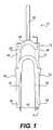
- FIG. 1is a front view of a bicycle suspension fork including a gas spring suspension system in accordance with one embodiment of the present invention
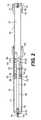
- FIG. 2is a cross-sectional view taken along line A-A of a leg of the suspension fork of FIG. 1 containing the gas spring suspension system;
- FIG. 3is a cross-sectional view of the fork leg shown in FIG. 2 showing the fork under compression.
- FIGS. 1-3illustrate a bicycle front suspension fork 10 that includes a gas spring suspension system 12 in accordance with one embodiment of the present invention.
- the gas spring assembly 12generally includes an upper tube 14 slidable in a lower tube 16 , a piston assembly 18 , first, second and third gas chambers 20 , 22 , 24 and a floating piston 26 slidably mounted in the upper tube 14 .
- the fork 10includes a crown 28 that is connected to a steerer tube 30 , a first leg 32 and second leg 34 .
- Each of the legs 32 , 34includes the upper tube 14 slidable within the lower tube 16 .
- the lower tubemay be slidable within the upper tube.
- the upper and lower tubes 14 , 16are connected at their remotes ends 36 to the crown 28 and at remote end s 38 to a wheel axle (not shown) through dropouts 40 .
- the gas spring suspensionmay be also embodied in a rear shock, seat post, or at other locations on a bicycle frame. Further, the gas spring suspension system of the present invention may be used on motorcycles as well as other handlebar-steered vehicles.
- the upper tube 14slides within the lower tube 16 during compression and rebound of the suspension system.
- the upper tube 14has a first end 42 sealed by a cap assembly 46 and a second end 44 is enclosed by an end plate 48 .
- the piston assembly 18generally includes a piston 54 and a piston rod 56 having a central bore 58 .
- the piston 54is slidably mounted within the upper tube 14 for reciprocation therein in response to compression or rebound of the upper and lower tubes 14 , 16 relative to each other.
- the piston rod 56has first end 53 connected to the piston 54 and extends through the second end 44 of the upper tube 14 .
- a second end 55 of the piston rod 56is secured to the lower tube 16 by a nut 60 .
- the piston 54includes an O-ring 62 that forms a gas-tight seal with the upper tube 14 .
- the piston assembly 18may further include a top-out bumper 63 to absorb the impact of the piston 54 contacting the floating piston 26 during rebound.
- the top-out bumper 63is disposed adjacent to a first surface 68 of the piston 54 .
- the first gas chamber 20is located between the cap assembly 46 and a second surface 64 of the piston 54 .
- the cap assembly 46includes a cap 47 having an O-ring 66 that forms a gas-tight seal with an inner wall of the upper tube 14 .
- the first gas chamber 20functions as a positive spring that biases the upper and lower tubes 14 , 16 toward each other.
- the second gas chamberfunctions as a negative spring that biases the upper and lower tubes 14 , 16 toward each other.
- the distance between the second end 44 of the upper tube 14 and the second end 52 of the lower tube 16is called the travel of the fork 10 .
- the second gas chamber 22includes two volumes, the volume inside of the central bore 58 of the piston rod 56 and the volume between the first surface 68 of the piston 54 and the floating piston 26 .
- the two volumes of the second gas chamber 22are in constant communication through passages 70 in the piston rod 56 and thus the two volumes function as a single volume.
- the cap assembly 46also includes a first inflation valve such as a Schrader valve 72 threaded into the cap 47 for pressurizing the first gas chamber 20 with gas.
- the second gas chamber 22is pressurized with gas through a second inflation valve such as a Schrader valve 74 disposed in the central bore 58 at the second end 55 of the piston rod 56 .
- the third gas chamber 24is located between the floating piston 26 and the second end 52 of the lower tube 16 . The gas in the third gas chamber 24 is air trapped during assembly of the fork 10 .
- the floating piston 26is slidably mounted within a lower end of the upper tube 14 .
- the floating piston 26is slidable along the piston rod 56 and the upper tube 14 and is biased against the end plate 48 by the pressure of the second gas chamber 22 and the piston 54 .
- the floating piston 26includes internal and external O-rings that form a gas-tight seal with the piston rod 56 and the upper tube 14 , respectively.
- the floating piston 26is prevented from being forced out of the upper tube 14 by the end plate 48 .
- a retaining ring 78fixes the end plate 48 to the second end 44 of the upper tube 14 .
- the end plate 48may be formed integrally with the second end 44 of the upper tube 14 .
- the end plate 48does not form a gas-tight seal with the upper tube 14 .
- the end plate 48may include a bumper 80 absorbs the impact of the floating piston 26 contacting the end plate 48 and a compression limiter 82 that ensures the bumper 80 is not overstressed during rebound.
- FIG. 2shows the fork leg 34 in an uncompressed or an extended state
- FIG. 3shows the fork leg 34 in a compressed state.
- the piston 54displaces towards the first end 42 of the upper tube 14 , increasing the pressure in the first gas chamber 20 and decreasing the pressure in the second gas chamber 22 .
- the volume of the third gas chamber 24decreases and the pressure in the third gas chamber 24 increases.
- the floating piston 26displaces towards the first end 42 of the upper tube 14 , resulting in a decrease in the pressure in the third gas chamber 24 and an increase in the pressure in the second gas chamber 22 .
Landscapes
- Engineering & Computer Science (AREA)
- General Engineering & Computer Science (AREA)
- Mechanical Engineering (AREA)
- Fluid-Damping Devices (AREA)
- Axle Suspensions And Sidecars For Cycles (AREA)
Abstract
Description
Claims (10)
Priority Applications (1)
| Application Number | Priority Date | Filing Date | Title |
|---|---|---|---|
| US12/175,547US7837180B2 (en) | 2005-09-14 | 2008-07-18 | Gas spring suspension system |
Applications Claiming Priority (2)
| Application Number | Priority Date | Filing Date | Title |
|---|---|---|---|
| US11/162,537US7401800B2 (en) | 2005-09-14 | 2005-09-14 | Gas spring suspension system |
| US12/175,547US7837180B2 (en) | 2005-09-14 | 2008-07-18 | Gas spring suspension system |
Related Parent Applications (1)
| Application Number | Title | Priority Date | Filing Date |
|---|---|---|---|
| US11/162,537ContinuationUS7401800B2 (en) | 2005-09-14 | 2005-09-14 | Gas spring suspension system |
Publications (2)
| Publication Number | Publication Date |
|---|---|
| US20080272570A1 US20080272570A1 (en) | 2008-11-06 |
| US7837180B2true US7837180B2 (en) | 2010-11-23 |
Family
ID=37854284
Family Applications (2)
| Application Number | Title | Priority Date | Filing Date |
|---|---|---|---|
| US11/162,537Expired - LifetimeUS7401800B2 (en) | 2005-09-14 | 2005-09-14 | Gas spring suspension system |
| US12/175,547Expired - Fee RelatedUS7837180B2 (en) | 2005-09-14 | 2008-07-18 | Gas spring suspension system |
Family Applications Before (1)
| Application Number | Title | Priority Date | Filing Date |
|---|---|---|---|
| US11/162,537Expired - LifetimeUS7401800B2 (en) | 2005-09-14 | 2005-09-14 | Gas spring suspension system |
Country Status (1)
| Country | Link |
|---|---|
| US (2) | US7401800B2 (en) |
Cited By (3)
| Publication number | Priority date | Publication date | Assignee | Title |
|---|---|---|---|---|
| US20090107780A1 (en)* | 2007-10-31 | 2009-04-30 | Ryu Yazaki | Method of assembling a hydraulic shock absorber and hydraulic shock absorber |
| US20130313803A1 (en)* | 2012-05-25 | 2013-11-28 | Hayes Bicycle Group, Inc. | Rubber isolation system incorporated between the compression rod and the gas spring assembly of a bicycle fork |
| US12442429B2 (en) | 2021-05-12 | 2025-10-14 | Vorsprung Technologies, Ltd. | High dynamic range suspension apparatus with selective fluid pressure communication |
Families Citing this family (21)
| Publication number | Priority date | Publication date | Assignee | Title |
|---|---|---|---|---|
| US20080296814A1 (en) | 2002-06-25 | 2008-12-04 | Joseph Franklin | Gas spring with travel control |
| US7703585B2 (en) | 2002-06-25 | 2010-04-27 | Fox Factory, Inc. | Integrated and self-contained suspension assembly having an on-the-fly adjustable air spring |
| US10941828B2 (en) | 2002-06-25 | 2021-03-09 | Fox Factory, Inc. | Gas spring with travel control |
| US8464850B2 (en) | 2006-11-16 | 2013-06-18 | Fox Factory, Inc. | Gas spring curve control in an adjustable-volume gas-pressurized device |
| US7963509B2 (en) | 2007-01-31 | 2011-06-21 | Fox Factory, Inc. | Travel control for a gas spring and gas spring having very short travel modes |
| DE102006022473A1 (en)* | 2006-05-13 | 2007-11-15 | Gustav Magenwirth Gmbh & Co. Kg | fork |
| US7520521B2 (en)* | 2007-01-24 | 2009-04-21 | Jung-Yu Hsu | Front fork having an air pump |
| US8123006B1 (en)* | 2007-04-13 | 2012-02-28 | Hayes Bicycle Group, Inc. | Lightweight gas spring design with volume compensator incorporated into a suspension fork for two wheeled vehicles |
| US20090001684A1 (en)* | 2007-06-29 | 2009-01-01 | Specialized Bicycle Components, Inc. | Bicycle suspension assembly |
| US9150075B2 (en) | 2008-03-19 | 2015-10-06 | Fox Factory, Inc. | Methods and apparatus for suspending vehicles |
| US20100244340A1 (en) | 2008-03-19 | 2010-09-30 | Wootten Dennis K | Methods and apparatus for combined variable damping and variable spring rate suspension |
| US8869959B2 (en) | 2008-07-24 | 2014-10-28 | Fox Factory, Incorporated | Vehicle suspension damper |
| US9156325B2 (en) | 2008-03-19 | 2015-10-13 | Fox Factory, Inc. | Methods and apparatus for vehicle suspension having multiple gas volumes |
| US7900947B2 (en)* | 2008-07-31 | 2011-03-08 | Shimano Inc. | Bicycle suspension system |
| JP2011053053A (en)* | 2009-09-01 | 2011-03-17 | Sumitomo Wiring Syst Ltd | Rotation detection device |
| US8256787B2 (en)* | 2009-10-08 | 2012-09-04 | Shimano Inc. | Adjustable bicycle suspension system |
| US8511448B2 (en)* | 2010-02-01 | 2013-08-20 | Trek Bicycle Corp. | Bicycle air shock assemblies with tunable suspension performance |
| JP5847612B2 (en)* | 2012-02-29 | 2016-01-27 | 株式会社ショーワ | Spring leg for front fork |
| US10131391B2 (en)* | 2016-05-25 | 2018-11-20 | Shimano Inc. | Bicycle seatpost assembly |
| TWI639528B (en)* | 2017-02-23 | 2018-11-01 | 台灣穗高工業股份有限公司 | Bicycle seat post structure |
| US9957008B1 (en)* | 2017-03-06 | 2018-05-01 | Taiwan Hodaka Industrial Co., Ltd. | Bicycle seatpost structure |
Citations (8)
| Publication number | Priority date | Publication date | Assignee | Title |
|---|---|---|---|---|
| US5195766A (en) | 1990-06-05 | 1993-03-23 | Boge Ag | Bicycle with front fork suspension |
| US5417446A (en) | 1994-09-08 | 1995-05-23 | Halson Designs, Inc. | Air damping for bicycle shock absorbing fork |
| US5580075A (en) | 1994-06-06 | 1996-12-03 | Rockshox, Inc. | Bicycle fork suspension with exchangeable spring unit |
| US6105988A (en) | 1997-07-16 | 2000-08-22 | Rockshox, Inc. | Adjustable suspension system having positive and negative springs |
| US6135434A (en) | 1998-02-03 | 2000-10-24 | Fox Factory, Inc. | Shock absorber with positive and negative gas spring chambers |
| US6505719B2 (en) | 1998-05-18 | 2003-01-14 | Answer Products, Inc. | Damping apparatus for bicycle forks |
| US6581948B2 (en) | 2001-08-30 | 2003-06-24 | Fox Factory, Inc. | Inertia valve shock absorber |
| US6592136B2 (en) | 2001-07-02 | 2003-07-15 | Fox Factory, Inc. | Bicycle fork cartridge assembly |
- 2005
- 2005-09-14USUS11/162,537patent/US7401800B2/ennot_activeExpired - Lifetime
- 2008
- 2008-07-18USUS12/175,547patent/US7837180B2/ennot_activeExpired - Fee Related
Patent Citations (8)
| Publication number | Priority date | Publication date | Assignee | Title |
|---|---|---|---|---|
| US5195766A (en) | 1990-06-05 | 1993-03-23 | Boge Ag | Bicycle with front fork suspension |
| US5580075A (en) | 1994-06-06 | 1996-12-03 | Rockshox, Inc. | Bicycle fork suspension with exchangeable spring unit |
| US5417446A (en) | 1994-09-08 | 1995-05-23 | Halson Designs, Inc. | Air damping for bicycle shock absorbing fork |
| US6105988A (en) | 1997-07-16 | 2000-08-22 | Rockshox, Inc. | Adjustable suspension system having positive and negative springs |
| US6135434A (en) | 1998-02-03 | 2000-10-24 | Fox Factory, Inc. | Shock absorber with positive and negative gas spring chambers |
| US6505719B2 (en) | 1998-05-18 | 2003-01-14 | Answer Products, Inc. | Damping apparatus for bicycle forks |
| US6592136B2 (en) | 2001-07-02 | 2003-07-15 | Fox Factory, Inc. | Bicycle fork cartridge assembly |
| US6581948B2 (en) | 2001-08-30 | 2003-06-24 | Fox Factory, Inc. | Inertia valve shock absorber |
Cited By (6)
| Publication number | Priority date | Publication date | Assignee | Title |
|---|---|---|---|---|
| US20090107780A1 (en)* | 2007-10-31 | 2009-04-30 | Ryu Yazaki | Method of assembling a hydraulic shock absorber and hydraulic shock absorber |
| US8267382B2 (en)* | 2007-10-31 | 2012-09-18 | Hitachi, Ltd. | Method of assembling a hydraulic shock absorber and hydraulic shock absorber |
| US20130313803A1 (en)* | 2012-05-25 | 2013-11-28 | Hayes Bicycle Group, Inc. | Rubber isolation system incorporated between the compression rod and the gas spring assembly of a bicycle fork |
| US9132881B2 (en)* | 2012-05-25 | 2015-09-15 | Hayes Bicycle Group, Inc. | Rubber isolation system incorporated between the compression rod and the gas spring assembly of a bicycle fork |
| US9988124B2 (en) | 2012-05-25 | 2018-06-05 | Hayes Bicycle Group Inc. | Suspension assembly |
| US12442429B2 (en) | 2021-05-12 | 2025-10-14 | Vorsprung Technologies, Ltd. | High dynamic range suspension apparatus with selective fluid pressure communication |
Also Published As
| Publication number | Publication date |
|---|---|
| US7401800B2 (en) | 2008-07-22 |
| US20080272570A1 (en) | 2008-11-06 |
| US20070057420A1 (en) | 2007-03-15 |
Similar Documents
| Publication | Publication Date | Title |
|---|---|---|
| US7837180B2 (en) | Gas spring suspension system | |
| US9765842B2 (en) | Suspension device | |
| US7195234B2 (en) | Adjustable gas spring suspension system | |
| US4159105A (en) | Shock absorber with adjustable spring load | |
| US6135434A (en) | Shock absorber with positive and negative gas spring chambers | |
| CN117566008A (en) | Pneumatic height-only seat post assembly | |
| US10500915B2 (en) | Shock absorber incorporating a floating piston | |
| US11345431B2 (en) | Pressurized telescopic front fork leg, front fork and vehicle | |
| US11376913B2 (en) | Shock absorber incorporating a floating piston | |
| US8448761B2 (en) | Valve mechanism for a gas suspension system | |
| US9731574B2 (en) | Shock absorber gas spring seal | |
| US6328292B1 (en) | Adjustable pneumatic spring | |
| CN115320767A (en) | Damping and shock-absorbing integrated wheelbarrow | |
| US20040145101A1 (en) | Coil and air suspension system | |
| US20050189685A1 (en) | Dual spring rate preload module with air adjustment | |
| EP2003047B1 (en) | Dual-function bicycle seat post assembly | |
| US20080315552A1 (en) | Dual-function bicycle seat post assembly | |
| CN217207477U (en) | Pneumatic suspension structure of motorcycle | |
| CN213442919U (en) | Full-pneumatic shock-absorbing front fork | |
| WO2002079021A2 (en) | Coil and air suspension system | |
| CN209176843U (en) | Simple electric bicycle front fork structure | |
| CN112032238B (en) | Aluminum alloy double-adjustable pneumatic inverted front shock absorber | |
| US20250313299A1 (en) | Front forks for bicycles | |
| CN211778710U (en) | Shock absorber | |
| CN120773859A (en) | Front fork for bicycle |
Legal Events
| Date | Code | Title | Description |
|---|---|---|---|
| AS | Assignment | Owner name:SRAM CORPORATION, ILLINOIS Free format text:ASSIGNMENT OF ASSIGNORS INTEREST;ASSIGNOR:JORDAN, BRIAN, MR.;REEL/FRAME:021257/0367 Effective date:20080718 | |
| AS | Assignment | Owner name:SRAM, LLC, ILLINOIS Free format text:MERGER;ASSIGNOR:SRAM CORPORATION;REEL/FRAME:021617/0263 Effective date:20080930 Owner name:SRAM, LLC,ILLINOIS Free format text:MERGER;ASSIGNOR:SRAM CORPORATION;REEL/FRAME:021617/0263 Effective date:20080930 | |
| AS | Assignment | Owner name:GENERAL ELECTRIC CAPITAL CORPORATION, AS ADMINISTR Free format text:SECURITY AGREEMENT;ASSIGNOR:SRAM, LLC;REEL/FRAME:021630/0135 Effective date:20080930 | |
| STCF | Information on status: patent grant | Free format text:PATENTED CASE | |
| AS | Assignment | Owner name:JPMORGAN CHASE BANK, N.A. AS ADMINISTRATIVE AGENT, Free format text:SECOND LIEN PATENT SECURITY AGREEMENT;ASSIGNORS:COMPOSITECH;SRAM LLC;REEL/FRAME:026869/0309 Effective date:20110607 Owner name:JPMORGAN CHASE BANK, N.A., AS ADMINISTRATIVE AGENT Free format text:FIRST LIEN PATENT SECURITY AGREEMENT;ASSIGNORS:COMPOSITECH;SRAM LLC;REEL/FRAME:026856/0464 Effective date:20110607 | |
| AS | Assignment | Owner name:SRAM, LLC, ILLINOIS Free format text:RELEASE BY SECURED PARTY;ASSIGNOR:JPMORGAN CHASE BANK, N.A., AS ADMINISTRATIVE AGENT;REEL/FRAME:030248/0914 Effective date:20130417 Owner name:COMPOSITECH, INC., ILLINOIS Free format text:RELEASE BY SECURED PARTY;ASSIGNOR:JPMORGAN CHASE BANK, N.A., AS ADMINISTRATIVE AGENT;REEL/FRAME:030248/0914 Effective date:20130417 | |
| FPAY | Fee payment | Year of fee payment:4 | |
| MAFP | Maintenance fee payment | Free format text:PAYMENT OF MAINTENANCE FEE, 8TH YEAR, LARGE ENTITY (ORIGINAL EVENT CODE: M1552) Year of fee payment:8 | |
| FEPP | Fee payment procedure | Free format text:MAINTENANCE FEE REMINDER MAILED (ORIGINAL EVENT CODE: REM.); ENTITY STATUS OF PATENT OWNER: LARGE ENTITY | |
| LAPS | Lapse for failure to pay maintenance fees | Free format text:PATENT EXPIRED FOR FAILURE TO PAY MAINTENANCE FEES (ORIGINAL EVENT CODE: EXP.); ENTITY STATUS OF PATENT OWNER: LARGE ENTITY | |
| STCH | Information on status: patent discontinuation | Free format text:PATENT EXPIRED DUE TO NONPAYMENT OF MAINTENANCE FEES UNDER 37 CFR 1.362 | |
| FP | Lapsed due to failure to pay maintenance fee | Effective date:20221123 |