US7835778B2 - Method and apparatus for surgical navigation of a multiple piece construct for implantation - Google Patents
Method and apparatus for surgical navigation of a multiple piece construct for implantationDownload PDFInfo
- Publication number
- US7835778B2 US7835778B2US10/687,539US68753903AUS7835778B2US 7835778 B2US7835778 B2US 7835778B2US 68753903 AUS68753903 AUS 68753903AUS 7835778 B2US7835778 B2US 7835778B2
- Authority
- US
- United States
- Prior art keywords
- pedicle screw
- relative
- tracking
- detector
- elongated rod
- Prior art date
- Legal status (The legal status is an assumption and is not a legal conclusion. Google has not performed a legal analysis and makes no representation as to the accuracy of the status listed.)
- Active, expires
Links
- 238000000034methodMethods0.000titleclaimsabstractdescription196
- 238000002513implantationMethods0.000titleclaimsabstractdescription37
- 230000004807localizationEffects0.000claimsdescription84
- 238000003384imaging methodMethods0.000claimsdescription56
- 239000007943implantSubstances0.000claimsdescription48
- 210000004872soft tissueAnatomy0.000claimsdescription41
- 239000004606Fillers/ExtendersSubstances0.000claimsdescription36
- 230000003287optical effectEffects0.000claimsdescription22
- 239000000523sampleSubstances0.000claimsdescription13
- 230000007246mechanismEffects0.000claimsdescription12
- 210000000988bone and boneAnatomy0.000claimsdescription6
- 238000001514detection methodMethods0.000claimsdescription5
- 238000003780insertionMethods0.000claimsdescription3
- 230000037431insertionEffects0.000claimsdescription3
- 239000000835fiberSubstances0.000claims3
- 241001653121GlenoidesSpecies0.000claims1
- 230000000881depressing effectEffects0.000claims1
- 210000003484anatomyAnatomy0.000description24
- 238000002591computed tomographyMethods0.000description14
- 210000004207dermisAnatomy0.000description11
- 238000002595magnetic resonance imagingMethods0.000description9
- 230000002500effect on skinEffects0.000description8
- 230000008569processEffects0.000description8
- 238000012876topographyMethods0.000description7
- 230000008859changeEffects0.000description5
- 230000004927fusionEffects0.000description5
- 238000002324minimally invasive surgeryMethods0.000description5
- 238000012014optical coherence tomographyMethods0.000description5
- 238000001356surgical procedureMethods0.000description5
- 238000002600positron emission tomographyMethods0.000description4
- 210000001519tissueAnatomy0.000description4
- 238000002604ultrasonographyMethods0.000description4
- 238000005516engineering processMethods0.000description3
- 238000013507mappingMethods0.000description3
- 238000005259measurementMethods0.000description3
- 230000005855radiationEffects0.000description3
- 210000002435tendonAnatomy0.000description3
- 238000012800visualizationMethods0.000description3
- 230000008901benefitEffects0.000description2
- 238000004891communicationMethods0.000description2
- 238000012790confirmationMethods0.000description2
- 230000035876healingEffects0.000description2
- 208000014674injuryDiseases0.000description2
- 210000003041ligamentAnatomy0.000description2
- 238000001454recorded imageMethods0.000description2
- 210000003491skinAnatomy0.000description2
- 230000008733traumaEffects0.000description2
- 238000012285ultrasound imagingMethods0.000description2
- 238000012795verificationMethods0.000description2
- OKTJSMMVPCPJKN-UHFFFAOYSA-NCarbonChemical compound[C]OKTJSMMVPCPJKN-UHFFFAOYSA-N0.000description1
- 101710163270NucleaseProteins0.000description1
- 206010052428WoundDiseases0.000description1
- 210000001264anterior cruciate ligamentAnatomy0.000description1
- 239000003242anti bacterial agentSubstances0.000description1
- 229940088710antibiotic agentDrugs0.000description1
- 230000003190augmentative effectEffects0.000description1
- 238000005452bendingMethods0.000description1
- 210000002805bone matrixAnatomy0.000description1
- 229910052799carbonInorganic materials0.000description1
- 239000003086colorantSubstances0.000description1
- 150000001875compoundsChemical class0.000description1
- 238000013170computed tomography imagingMethods0.000description1
- 238000012937correctionMethods0.000description1
- 230000007423decreaseEffects0.000description1
- 238000002059diagnostic imagingMethods0.000description1
- 238000006073displacement reactionMethods0.000description1
- 239000003814drugSubstances0.000description1
- 229940079593drugDrugs0.000description1
- 230000005672electromagnetic fieldEffects0.000description1
- 230000008030eliminationEffects0.000description1
- 238000003379elimination reactionMethods0.000description1
- 230000007613environmental effectEffects0.000description1
- 238000002594fluoroscopyMethods0.000description1
- 238000007429general methodMethods0.000description1
- 238000002675image-guided surgeryMethods0.000description1
- 238000002608intravascular ultrasoundMethods0.000description1
- 239000004973liquid crystal related substanceSubstances0.000description1
- 239000003550markerSubstances0.000description1
- 239000000463materialSubstances0.000description1
- 239000011159matrix materialSubstances0.000description1
- 238000002483medicationMethods0.000description1
- 210000003205muscleAnatomy0.000description1
- 230000002980postoperative effectEffects0.000description1
- 238000007639printingMethods0.000description1
- 238000011084recoveryMethods0.000description1
- 230000009467reductionEffects0.000description1
- 238000009877renderingMethods0.000description1
- 238000012360testing methodMethods0.000description1
- 230000001225therapeutic effectEffects0.000description1
- 238000002560therapeutic procedureMethods0.000description1
- 230000009466transformationEffects0.000description1
- 230000000007visual effectEffects0.000description1
Images


Classifications
- A—HUMAN NECESSITIES
- A61—MEDICAL OR VETERINARY SCIENCE; HYGIENE
- A61B—DIAGNOSIS; SURGERY; IDENTIFICATION
- A61B17/00—Surgical instruments, devices or methods
- A61B17/56—Surgical instruments or methods for treatment of bones or joints; Devices specially adapted therefor
- A61B17/58—Surgical instruments or methods for treatment of bones or joints; Devices specially adapted therefor for osteosynthesis, e.g. bone plates, screws or setting implements
- A61B17/88—Osteosynthesis instruments; Methods or means for implanting or extracting internal or external fixation devices
- A61B17/8872—Instruments for putting said fixation devices against or away from the bone
- A—HUMAN NECESSITIES
- A61—MEDICAL OR VETERINARY SCIENCE; HYGIENE
- A61B—DIAGNOSIS; SURGERY; IDENTIFICATION
- A61B17/00—Surgical instruments, devices or methods
- A61B17/16—Instruments for performing osteoclasis; Drills or chisels for bones; Trepans
- A61B17/17—Guides or aligning means for drills, mills, pins or wires
- A61B17/1735—Guides or aligning means for drills, mills, pins or wires for rasps or chisels
- A—HUMAN NECESSITIES
- A61—MEDICAL OR VETERINARY SCIENCE; HYGIENE
- A61B—DIAGNOSIS; SURGERY; IDENTIFICATION
- A61B17/00—Surgical instruments, devices or methods
- A61B17/16—Instruments for performing osteoclasis; Drills or chisels for bones; Trepans
- A61B17/17—Guides or aligning means for drills, mills, pins or wires
- A61B17/1739—Guides or aligning means for drills, mills, pins or wires specially adapted for particular parts of the body
- A61B17/1757—Guides or aligning means for drills, mills, pins or wires specially adapted for particular parts of the body for the spine
- A—HUMAN NECESSITIES
- A61—MEDICAL OR VETERINARY SCIENCE; HYGIENE
- A61B—DIAGNOSIS; SURGERY; IDENTIFICATION
- A61B17/00—Surgical instruments, devices or methods
- A61B17/56—Surgical instruments or methods for treatment of bones or joints; Devices specially adapted therefor
- A61B17/58—Surgical instruments or methods for treatment of bones or joints; Devices specially adapted therefor for osteosynthesis, e.g. bone plates, screws or setting implements
- A61B17/68—Internal fixation devices, including fasteners and spinal fixators, even if a part thereof projects from the skin
- A61B17/70—Spinal positioners or stabilisers, e.g. stabilisers comprising fluid filler in an implant
- A61B17/7074—Tools specially adapted for spinal fixation operations other than for bone removal or filler handling
- A61B17/7083—Tools for guidance or insertion of tethers, rod-to-anchor connectors, rod-to-rod connectors, or longitudinal elements
- A61B17/7089—Tools for guidance or insertion of tethers, rod-to-anchor connectors, rod-to-rod connectors, or longitudinal elements wherein insertion is along an arcuate path
- A—HUMAN NECESSITIES
- A61—MEDICAL OR VETERINARY SCIENCE; HYGIENE
- A61B—DIAGNOSIS; SURGERY; IDENTIFICATION
- A61B34/00—Computer-aided surgery; Manipulators or robots specially adapted for use in surgery
- A61B34/20—Surgical navigation systems; Devices for tracking or guiding surgical instruments, e.g. for frameless stereotaxis
- A—HUMAN NECESSITIES
- A61—MEDICAL OR VETERINARY SCIENCE; HYGIENE
- A61B—DIAGNOSIS; SURGERY; IDENTIFICATION
- A61B90/00—Instruments, implements or accessories specially adapted for surgery or diagnosis and not covered by any of the groups A61B1/00 - A61B50/00, e.g. for luxation treatment or for protecting wound edges
- A61B90/10—Instruments, implements or accessories specially adapted for surgery or diagnosis and not covered by any of the groups A61B1/00 - A61B50/00, e.g. for luxation treatment or for protecting wound edges for stereotaxic surgery, e.g. frame-based stereotaxis
- A—HUMAN NECESSITIES
- A61—MEDICAL OR VETERINARY SCIENCE; HYGIENE
- A61B—DIAGNOSIS; SURGERY; IDENTIFICATION
- A61B90/00—Instruments, implements or accessories specially adapted for surgery or diagnosis and not covered by any of the groups A61B1/00 - A61B50/00, e.g. for luxation treatment or for protecting wound edges
- A61B90/36—Image-producing devices or illumination devices not otherwise provided for
- A—HUMAN NECESSITIES
- A61—MEDICAL OR VETERINARY SCIENCE; HYGIENE
- A61B—DIAGNOSIS; SURGERY; IDENTIFICATION
- A61B90/00—Instruments, implements or accessories specially adapted for surgery or diagnosis and not covered by any of the groups A61B1/00 - A61B50/00, e.g. for luxation treatment or for protecting wound edges
- A61B90/39—Markers, e.g. radio-opaque or breast lesions markers
- A—HUMAN NECESSITIES
- A61—MEDICAL OR VETERINARY SCIENCE; HYGIENE
- A61B—DIAGNOSIS; SURGERY; IDENTIFICATION
- A61B17/00—Surgical instruments, devices or methods
- A61B17/00234—Surgical instruments, devices or methods for minimally invasive surgery
- A—HUMAN NECESSITIES
- A61—MEDICAL OR VETERINARY SCIENCE; HYGIENE
- A61B—DIAGNOSIS; SURGERY; IDENTIFICATION
- A61B17/00—Surgical instruments, devices or methods
- A61B2017/00477—Coupling
- A—HUMAN NECESSITIES
- A61—MEDICAL OR VETERINARY SCIENCE; HYGIENE
- A61B—DIAGNOSIS; SURGERY; IDENTIFICATION
- A61B34/00—Computer-aided surgery; Manipulators or robots specially adapted for use in surgery
- A61B34/10—Computer-aided planning, simulation or modelling of surgical operations
- A61B2034/107—Visualisation of planned trajectories or target regions
- A—HUMAN NECESSITIES
- A61—MEDICAL OR VETERINARY SCIENCE; HYGIENE
- A61B—DIAGNOSIS; SURGERY; IDENTIFICATION
- A61B34/00—Computer-aided surgery; Manipulators or robots specially adapted for use in surgery
- A61B34/20—Surgical navigation systems; Devices for tracking or guiding surgical instruments, e.g. for frameless stereotaxis
- A61B2034/2046—Tracking techniques
- A61B2034/2055—Optical tracking systems
- A—HUMAN NECESSITIES
- A61—MEDICAL OR VETERINARY SCIENCE; HYGIENE
- A61B—DIAGNOSIS; SURGERY; IDENTIFICATION
- A61B34/00—Computer-aided surgery; Manipulators or robots specially adapted for use in surgery
- A61B34/20—Surgical navigation systems; Devices for tracking or guiding surgical instruments, e.g. for frameless stereotaxis
- A61B2034/2068—Surgical navigation systems; Devices for tracking or guiding surgical instruments, e.g. for frameless stereotaxis using pointers, e.g. pointers having reference marks for determining coordinates of body points
- A—HUMAN NECESSITIES
- A61—MEDICAL OR VETERINARY SCIENCE; HYGIENE
- A61B—DIAGNOSIS; SURGERY; IDENTIFICATION
- A61B34/00—Computer-aided surgery; Manipulators or robots specially adapted for use in surgery
- A61B34/20—Surgical navigation systems; Devices for tracking or guiding surgical instruments, e.g. for frameless stereotaxis
- A61B2034/2072—Reference field transducer attached to an instrument or patient
- A—HUMAN NECESSITIES
- A61—MEDICAL OR VETERINARY SCIENCE; HYGIENE
- A61B—DIAGNOSIS; SURGERY; IDENTIFICATION
- A61B34/00—Computer-aided surgery; Manipulators or robots specially adapted for use in surgery
- A61B34/25—User interfaces for surgical systems
- A61B2034/256—User interfaces for surgical systems having a database of accessory information, e.g. including context sensitive help or scientific articles
- A—HUMAN NECESSITIES
- A61—MEDICAL OR VETERINARY SCIENCE; HYGIENE
- A61B—DIAGNOSIS; SURGERY; IDENTIFICATION
- A61B90/00—Instruments, implements or accessories specially adapted for surgery or diagnosis and not covered by any of the groups A61B1/00 - A61B50/00, e.g. for luxation treatment or for protecting wound edges
- A61B90/36—Image-producing devices or illumination devices not otherwise provided for
- A61B2090/364—Correlation of different images or relation of image positions in respect to the body
- A61B2090/365—Correlation of different images or relation of image positions in respect to the body augmented reality, i.e. correlating a live optical image with another image
- A—HUMAN NECESSITIES
- A61—MEDICAL OR VETERINARY SCIENCE; HYGIENE
- A61B—DIAGNOSIS; SURGERY; IDENTIFICATION
- A61B90/00—Instruments, implements or accessories specially adapted for surgery or diagnosis and not covered by any of the groups A61B1/00 - A61B50/00, e.g. for luxation treatment or for protecting wound edges
- A61B90/39—Markers, e.g. radio-opaque or breast lesions markers
- A61B2090/3983—Reference marker arrangements for use with image guided surgery
- A—HUMAN NECESSITIES
- A61—MEDICAL OR VETERINARY SCIENCE; HYGIENE
- A61B—DIAGNOSIS; SURGERY; IDENTIFICATION
- A61B34/00—Computer-aided surgery; Manipulators or robots specially adapted for use in surgery
- A61B34/10—Computer-aided planning, simulation or modelling of surgical operations
- A—HUMAN NECESSITIES
- A61—MEDICAL OR VETERINARY SCIENCE; HYGIENE
- A61B—DIAGNOSIS; SURGERY; IDENTIFICATION
- A61B34/00—Computer-aided surgery; Manipulators or robots specially adapted for use in surgery
- A61B34/25—User interfaces for surgical systems
Definitions
- the present inventionrelates to surgical navigation for assembly and implantation of a multi-piece construct into an anatomy; and particularly to a method and apparatus for percutaneous and/or minimally invasive implantation of constructs into a selected portion of an anatomy.
- Image guided medical and surgical proceduresutilize patient images obtained prior to or during a medical procedure to guide a physician performing the procedure.
- Recent advances in imaging technology, especially in imaging technologies that produce highly-detailed, two, three, and four dimensional images, such as computed tomography (CT), magnetic resonance imaging (MRI), fluoroscopic imaging, positron emission tomography (PET), and ultrasound imaging (US)has increased the interest in image guided medical procedures.
- Image guided surgical techniqueshave been used to assist surgeons and individuals in various surgical procedures.
- Various image based navigation systemsinclude U.S. Pat. No. 6,470,207, entitled “Navigational Guidance Via Computer-Assisted Fluoroscopic Imaging”, issued Oct. 22, 2002, which is hereby incorporated by reference in its entirety; and image based systems such as the STEALTHSTATION, and various improvements such as the TREON and ION sold by Medtronic Surgical Navigation Technologies of Louisville, Colo.
- the procedures and instruments used with image guided surgeryallow for visualization or virtual visualization of surgical instruments and various anatomical portions in relation to preacquired or real-time images. Representations of the instruments and implants are generally super-imposed over the preacquired or real-time images of the patients anatomy. Nevertheless, these systems generally require registration of the image data to the patient such that the image data used to guide the procedure matches the patient's intra-operative orientation known as patient space.
- a spinal fusion proceduremay be performed according to various known techniques.
- an image based navigation systemsuch as those discussed above, may be used to assist in a spinal fusion procedure.
- the navigation systemgenerally requires the acquisition of a patient image and a registration of the patient image with the surgical patient space to ensure proper guiding and navigation of the instruments and implant portions. Therefore, the image based navigation systems require use of various image acquisition components in an operative procedure, such as the fluoroscopic device, a magnetic resonance imaging (MRI) device, or other image capturing devices.
- MRImagnetic resonance imaging
- These imagesare then registered relative to the patient, generally using known registration techniques, such as automatic registration, user guided registration, 2D or 3D registration, point registration and surface registration.
- Dynamic referencingmay also be used to track patient movement during the procedure.
- a substantially open proceduremay be used to perform the spinal fusion, or anterior cruciate ligament replacement, acetabular implantation, femoral implantation, spinal disc nuclease replacement, spinal disc replacement, and the like.
- the soft tissue surrounding the spineparticularly a posterior portion of the spine, may be substantially opened or removed such that an “open” view of the spine may be obtained.
- the proceduremay continue with the user, such as a surgeon, having a clear view of the surgical area.
- the open proceduresrequire a large incision and movement of soft tissue. This large incision, movement of soft tissue, and necessary closures, often may require an extended recovery.
- Open proceduresmay also be supplemented with various systems, such as a device to mechanically customize connecting rods by MEDIVISION of Germany.
- This systemmay allow for bending of connecting rods to fix a selected geometry.
- the selected geometrymay be determined using any appropriate mechanism, such as a coordinated system or registration system to determine the appropriate angle and shape of the rod.
- a substantially percutaneous and/or minimally invasive proceduremay be used to position a construct to perform a spinal fusion.
- the various components of the constructare mechanically interconnected or held with an alignment instrument.
- a head of a pedicle screwmay be aligned with such an instrument.
- the instrumentmechanically guides a connector member to interconnect with each pedicle screw.
- the apparatiiinclude instruments or elements that can be localized by being sensed or detected with various instruments.
- optical or electromagnetic (EM) localization techniquesmay be used to determine the precise location of a selected implant construct or implantation instrument.
- an optical localizercan be positioned relative to an extender extending from implant element, such as a screw.
- a coilmay be positioned in an EM field such that the position of the coil may be determined by sensing the induced voltage, and vice versa.
- the apparatiisuch as a computer, may allow for the selection of various components that can be implanted to form the selected construct.
- a predetermined or selected outcomecan be used to provide or form a selected construct from various components such that the selected outcome may be achieved.
- the various instrumentsmay be used to plan and select intraoperatively the various portions of the construct that may be positioned relative to the anatomy.
- the various instrumentsmay be used to guide and track the various portions of the construct to ensure that the selected plan is achieved. Therefore, a plan may be formulated prior to the implantation of at least all of the construct to ensure the achievement of the selected outcome.
- the actual proceduremay be performed using the selected plan and the procedure may be monitored, tracked, and navigated to ensure that the selected outcome is achieved. The whole process may be performed in an imageless manner and, thereby, without a need to register images with the patient space.
- a system for use in navigating an implantation of a selected constructincludes a first member and a second member of the construct adapted to selectively interact with each other after implantation.
- a localization elementis selectively associated with at least one of the first member and the second member.
- a detectoris able to detect the localization element when the localization element is associated with at least one of the first member and the second member.
- a processoris operable to assist in navigation of the second member relative to the first member.
- the processoris operable to receive position information for at least one of the first member and the second member from the detector and further operable to determine a relative position of the other of the at least one of the first member and the second member.
- the relative positionis operable to allow a navigation of at least one of the first member and the second member.
- a system for use in determining a position of a first implantable member and planning and navigating relative to the first member for positioning a second member to interact with the first memberincludes a tracking element associated with the first member to assist in determining a position of the first member.
- a first detectordetects the tracking element and a processor determines a position of the first member depending upon the detection of the first detector.
- a navigable instrumentis operable to move the second member relative to the first member; and a second detector detects the navigable instrument.
- the processoris operable to determine a position of the second member relative to the first member in at least two planes.
- the processoris operable to navigate the navigable instrument relative to the tracking element for positioning of the second member relative to the first member.
- a method of percutaneous and/or minimally invasive implantation of a construct having at least a first member, a second member, and a third memberincludes positioning the first member and determining a position of the first member in a selected space. The method further includes positioning the second member relative to the first member and determining a position of the second member in the selected space. Also, navigating the third member relative to the first member and the second member may be performed. The navigation generally includes determining a real time optimal position of the third member in the selected space; and determining a real time position of the third member relative to at least one of the first member and the second member.
- a method of implanting a construct of at least a first member, a second member, and a third member substantially percutaneously and/or minimally invasiveincludes selecting a final orientation of at least one of the first member, the second member, and the third member relative to at least one other of the first member, the second member, and the third member.
- a determination of the position of the first member and the second member and displaying the position of each of the first member and the second memberis also performed.
- a characteristic of at least one of the first member, the second member, and the third memberis selected. Also, positioning with navigation at least one of the first member, the second member, and the third member relative to another of at least one of the first member, the second member, and the third member to achieve the selected final orientation.
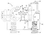
- FIG. 1is an environmental view of a surgical navigation system including an optional imaging system
- FIG. 2Ais an ideal calibration image for the optional imaging system
- FIG. 2Bis a non-ideal calibration image for the optional imaging system
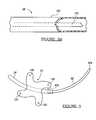
- FIG. 3Ais a construct according to an embodiment
- FIG. 3 bis a connector for the construct of FIG. 3 a according to various embodiments
- FIGS. 4A-4Care localization units according to various embodiments.
- FIG. 5is a navigable instrument to assist in positioning a connector according to various embodiments
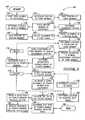
- FIG. 6is a flow chart for a method of implanting and navigating a selected construct according to various embodiments
- FIG. 7Ais a partial detailed view of a portion of a spine including a portion of a construct localization element affixed thereto;
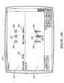
- FIG. 7Bis a screen produced by the navigation system display indicating a location of a first portion of a construct
- FIG. 8Ais a partial detailed view of the spine including two portions of a construct and a localization element affixed thereto;
- FIG. 8Bis a screen produced by a surgical navigation system including two portions of the construct
- FIG. 9Ais a display produced by the surgical navigation system for planning the procedure
- FIG. 9Bis a partial detailed view of a portion of the spine including an element to assist in positioning a third portion of the construct
- FIG. 10Ais a partial detailed view of the spine including three portions of a construct including localization elements affixed thereto according to various embodiments;
- FIG. 10Bis a screen produced by the surgical navigation system to assist in positioning a third member of the construct
- FIG. 11Ais a partial detailed view of the spine including a probe to determine a contour of soft tissue surrounding the spine;
- FIG. 11Bis a screen produced by the surgical navigation system including an optional image of the anatomical portions
- FIG. 12Ais a partial detailed view of the spine including a connector that is navigable relative to other construct portions;
- FIG. 12Bis a virtual view of the connector interconnecting the various portions of the construct and assisting in the navigation thereof according to various embodiments;
- FIG. 13Ais a partial detailed view of the spine including the construct assembled.
- FIG. 13Bis a screen produced by the surgical navigation system to indicate completion of the procedure and optional confirmation using the optional imaging system.
- implantssuch as multi-component implants that require positioning of one component relative to another component may be implanted according to selected constructs using instruments and methods similar to those described herein.
- These implantsmay include joint implant, soft tissue implant, such as ligament implants, tendon implants and spinal disc implants, and others.
- the proceduremay occur in any appropriate manner.
- the proceduremay be substantially open, or percutaneously or minimally invasively. Therefore, it will be understood that the description of the procedure is not intended to be limited to any particular form of a procedure.
- a percutaneous and a minimally invasive proceduremay be similar in regarding the small size of incisions, when compared to open procedures, to perform the procedure.
- a percutaneous and/or minimally invasive procedureincludes a substantially small incision such that a portion of the operative site is covered by dermis tissue and dermis tissue healing time is reduced.
- an open proceduremay also be percutaneous as occurring generally through the skin and generally include a puncture wound.
- a surgical navigation system 20which may include any appropriate surgical navigation system, is illustrated.
- the surgical navigation system 20may include an optical navigation system, an electromagnetic navigation system, and acoustic navigation system, an ultrasound, or any other appropriate navigation system.
- an optical navigation systeman electromagnetic navigation system
- acoustic navigation systeman ultrasound, or any other appropriate navigation system.
- Exemplary electromagnetic navigation systemsare set out in U.S. Pat. No. 6,493,573, issued Dec. 10, 2002, entitled “METHOD AND SYSTEM FOR NAVIGATING A CATHETER PROBE IN THE PRESENCE OF FIELD-INFLUENCING OBJECTS”; U.S. Pat. No.
- the surgical navigation system 20generally includes an optical detector 22 operably connected to a computer or processor 24 through an appropriate communication line 26 .
- the detector 22may also include a plurality of detector. Each of the plurality of detectors may be able to detect a different source, such as EM or optical. Therefore, the navigation system 20 may be able to detect more than one tracking element.
- the line 26may be any appropriate line and may also be a wireless connection. Therefore, the detector 22 may be positioned anywhere relative to the navigation computer 24 and communicates therewith over the line 26 .
- a monitor or display 28may be provided for a user to view, such as a surgeon 30 .
- the monitor 28may be any appropriate monitor and may also include a heads-up or head mounted display. Nevertheless, it will be understood that the monitor 28 is able to display an image produced by the computer 24 based upon a preset program or user input according to the teachings of the present invention.
- the detector 22may be operably located in any appropriate location such that the detector 22 is able to detect a tracking element 34 operably connected to a selected instrument 36 .
- the detector 22may also be operable to detect any other appropriate tracking element.
- the detector 22may also be able to detect an optional dynamic tracking reference element 38 .
- the dynamic tracking element 38may not be necessary depending upon the selected parameters for the surgical navigation system 20 , the procedure being performed, user preference, and other appropriate considerations, further discussed herein. Nevertheless, if the dynamic reference tracking element 38 is selected to be used, the dynamic tracking reference 38 is generally affixed to a patient 40 .
- the patient 40is generally positioned on a selected platform or operating room (OR) table 42 for the procedure.
- the tracking element 34may include any appropriate tracking portion, that may depend on the various navigation systems.
- Various examplesinclude a tracking element selected from a group including an electromagnetic tracking device, an optical tracking device, a conductive tracking device, a fiberoptic tracking device, an acoustic tracking device, and combinations thereof.
- the detectormay be formed to detected any of these tracking elements.
- an optical navigation systemincludes the tracking element 34 that may include a selected number of reflectors to reflect a light source or a light source, such as light emitting diodes (LEDs).
- the detector 22is able to detect the light emitted to determine a position of the tracking element.
- a coilmay either transmit a field or detect a field to determine a location.
- the EM systemsmay help eliminate issues such as line of sight, such as when an opaque object blocks the path of the light from the tracking element 34 .
- the user 30may use any appropriate input device 44 , element such as a foot pedal, to input a selected input into the navigation computer 24 .
- the monitor 28may include a touch screen, or other appropriate mechanisms such as a mouse or computer keyboard as the input device 44 .
- the navigation system 20is generally able to navigate and determine a location of the tracking elements.
- an implant or secondary dynamic tracking element 46may also be provided.
- the implant tracking element 46may be interconnected to a selected implant to determine a location of the selected implant after it is implanted into the patient 40 .
- the implant tracking element 46may also be used to track the implant during any appropriate time such as during implantation, after implantation, or even before implantation for various reasons, such as determining an appropriate implantation position.
- the detector 22is able to optically locate the various tracking elements 34 , 38 and 46 .
- the location of the tracking elementsmay be referenced to any appropriate reference.
- the tracking elementsmay be referenced to any position within the detector space, which is the space that is detectable by the detector 22 .
- the tracking elements 34 , 38 and 46may be referenced to a patient space which is defined by the space or area under which the procedure is being performed relative to the patient 40 .
- the detector 22may detect, and the surgical navigation system 20 navigate, the various tracking elements relative to images that may be acquired pre-, intra-, or post operatively.
- the detector 22is able to locate the various elements according to any appropriate space for navigation by the navigation computer 24 for selected display on the monitor 28 .
- the navigation computer 24may navigate the selected instruments relative to selected points, such as a position of an implant, further discussed herein.
- an optional image acquisition system 50may also be used, if desired.
- the optional imaging device 50may be used to acquire any appropriate pre-operative or real time images of the patient 20 .
- the optional imaging device 50may be provided to obtain pre-operative imaging, such as magnetic resonance imaging (MRI), fluoroscopic, x-ray, and other appropriate or selected images. If pre-operative images are obtained, the pre-operative images may be used to plan a selected procedure depending upon the data acquired from the pre-operative images. On the day of the procedure, the optional imaging device 50 may also be used to image the patient 40 for any selected purpose.
- MRImagnetic resonance imaging
- This imagemay be used for pre-operative planning, for scaling, morphing, translating or merging atlas maps or 3-D models, and to verify that the construct has been assembled properly.
- the atlas mapmay also be scaled or morphed to the known location, based upon the size and orientation of the implant, such as the screw.
- the optional imaging device 50may be selected from any appropriate imaging device such as a computer aided topography (CT) imaging device or a fluoroscopic x-ray imaging device. If the optional imaging device 50 is a CT device, the patient generally has a series of CT scans taken on the area of interest for the selected procedure.
- CTcomputer aided topography
- the optional imaging device 50is the fluoroscopic device
- a plurality or selected number of fluoroscopic x-ray imagesmay also be taken.
- the pre-operative and intra-operative or immediate operative imagesmay then be merged or referenced depending upon selected procedures.
- the pre-operative and intra-operative imagesmay include anatomical landmarks that may be referenced by the navigation computer 24 and used to merge or register one set of the images with another set of images or to register the images to patient space as is known in the art.
- Various exemplary image fusing systemsinclude those set forth in U.S. patent application Ser. No. 10/644,680, filed Aug. 20, 2003 entitled “Method and Apparatus for Performing 2D to 3D Registration”, which is incorporated herein by reference.
- fiducial markersmay be referenced by both the pre and intra-operative images.
- distinct identifiable fiducial markersmay be attached to the patient 40 during the pre-operative scans, such as with the MRI.
- the fiducial markersare generally identifiable in the MRI image dataset by a user or a selected computer.
- the fiducial markersare generally not removed from the patient after the pre-operative images are obtained and the data is captured such that they are also visible on the later acquired images, such as with the CT or fluoroscopic image.
- the pre-operative and the intra-operative datasetscan be identified thus allowing merging or registration of the images or registration between the images and patient space.
- Other image or merging registration techniquesinclude the use of surface contours or anatomical landmarks which can either be manually or automatically identified by the processor 24 to provide various merging and registration options, as is known in the art.
- the optional imaging device 50may include a fluoroscopic x-ray imaging device that may be used in a place of other approximate imaging devices, such as CT imaging. Similar registration techniques may be used to register the pre-acquired image dataset with the later acquired image dataset such as from the fluoroscopic x-ray imaging system and with the patient space.
- the fluoroscopic x-ray imaging deviceif used as the optional imaging device 50 , may include a fluoroscopic device 52 , having an x-ray source 54 , and x-ray receiving section 56 , and may include an optional calibration and tracking targets and optional radiation sensors, such as those known in the art. Also a tracking element 57 may be included on the optional imaging device 50 , particularly on the receiving section 56 .
- the calibration and tracking targetgenerally includes calibration markers 58 (See FIGS. 2A-2B ), further discussed herein.
- Such optional imaging systemsmay include those described in U.S. Pat. No. 6,470,207, issued Oct. 22, 2002, entitled “Navigational Guidance Via Computer-Assisted Fluoroscopic Imaging” which is hereby incorporated by reference.
- a fluoroscopic device controller 60captures the x-ray images received at the receiving section 56 and stores the images for later use.
- the fluoroscopic device controller 60may also control the rotation of the fluoroscopic device 52 .
- the fluoroscopic device 52may move in the direction of arrow A or rotate about the long axis of the patient 40 , allowing anterior or lateral views of the patient 40 to be imaged. Each of these movements involve rotation about a mechanical axis 62 of the fluoroscopic device 52 .
- the long axis of the patient 40is substantially in line with the mechanical axis 62 of the fluoroscopic device 16 .
- fluoroscopic device 52This enables the fluoroscopic device 52 to be rotated relative to the patient 40 , allowing images of the patient 40 to be taken from multiple directions or about multiple planes.
- An example of a fluoroscopic device x-ray imaging device 50is the “Series 9600 Mobile Digital Imaging System,” from OEC Medical Systems, Inc., of Salt Lake City, Utah.
- Other exemplary fluoroscopesinclude bi-plane fluoroscopic systems, ceiling fluoroscopic systems, cath-lab fluoroscopic systems, fixed fluoroscopic device systems, isocentric fluoroscopic device systems, 3D fluoroscopic systems, etc.
- the imaging device 50generates x-rays from the x-ray source 54 that propagate through the patient 40 and a calibration and/or tracking target 64 , into the x-ray receiving section 56 .
- the receiving section 56generates an image representing the intensities of the received x-rays.
- the receiving section 56includes an image intensifier that first converts the x-rays to visible light and a charge coupled device (CCD) video camera that converts the visible light into digital images.
- CCDcharge coupled device
- Receiving section 56may also be a digital device that converts x-rays directly to digital images, thus potentially avoiding distortion introduced by first converting to visible light. With this type of digital, which is generally a flat panel device, the optional calibration and/or tracking target 64 and the calibration process discussed below may be eliminated.
- the calibration processmay be eliminated or not used depending on the type of therapy performed.
- the imaging device 50may only take a single image with the calibration and tracking target 64 in place. Thereafter, the calibration and tracking target 64 may be removed from the line-of-sight of the imaging device 50 .
- the imaging device 50is optional and may be utilized during the selected procedure, such as an implantation procedure, to merely confirm that the instrument has hit the desired target or that the construct has been assembled properly.
- Two dimensional fluoroscopic images taken by the imaging device 50are captured and stored in the fluoroscopic device controller 60 and/or directly within the various navigation or viewing systems. Multiple two-dimensional images taken by the imaging device 50 may also be captured and assembled to provide a larger view or image of a whole region of a patient 40 , as opposed to being directed to only a smaller portion or region of the patient 40 . For example, multiple image data of the patient's spine may be appended together to provide a full view or complete set of image data of the spine that may be used at a selected time. These images are then forwarded from the fluoroscopic device controller 60 to the controller, navigation computer or work station 24 having the display 28 and the user interface 44 .
- the navigation computer 24assembles the various images, but this may also be performed by the controller 60 .
- the data setmay be communicated over line 66 that may be a hard line or a wireless communication system.
- the work station 24provides facilities for displaying on the display 28 , saving, digitally manipulating, or printing a hard copy of the received images from both the imaging device 50 and from pre-operative scans, such as the preoperative MRI scans as discussed herein.
- the user interface 44may be a keyboard, mouse, touch pen, touch screen or other suitable device that allows a physician or user to provide inputs to control the imaging device 50 , via the fluoroscopic device controller 60 , or adjust the display settings of the display 28 .
- the work station 24may also direct the fluoroscopic device controller 60 to adjust the rotational axis 62 of the fluoroscopic device 52 to obtain various two-dimensional images along different planes in order to generate representative two-dimensional and three-dimensional images.
- the x-ray source 54When the x-ray source 54 generates the x-rays that propagate to the x-ray receiving section 56 , the radiation sensors sense the presence of radiation, which is forwarded to the fluoroscopic device controller 60 , to identify whether or not the imaging device 50 is actively imaging.
- a person or physicianmay manually indicate when the imaging device 50 is actively imaging or this function can be built into the x-ray source 54 , x-ray receiving section 56 , or the control computer 60 .
- Fluoroscopic imaging devices 50 that do not include a digital receiving section 56generally require the optional calibration and/or tracking target 64 . This is because the raw images generated by the receiving section 56 tend to suffer from undesirable distortion caused by a number of factors, including inherent image distortion in the image intensifier and external electromagnetic fields.
- An empty undistorted or ideal image and an empty distorted imageare shown in FIGS. 2A and 2B , respectively.
- the checkerboard shape, shown in FIG. 2Arepresents the ideal image 64 of the checkerboard arranged calibration markers 58 .
- the image taken by the receiving section 56can suffer from distortion, as illustrated by the distorted calibration marker image 70 , shown in FIG. 2B .
- Intrinsic calibrationwhich is the process of correcting image distortion in a received image and establishing the projective transformation for that image, involves placing the calibration markers 58 in the path of the x-ray, where the calibration markers 58 are opaque or semi-opaque to the x-rays.
- the calibration markers 58are rigidly arranged in pre-determined patterns in one or more planes in the path of the x-rays and are visible in the recorded images. Because the true relative position of the calibration markers 58 in the recorded images are known, the c fluoroscopic device controller 60 or the work station or computer 24 is able to calculate an amount of distortion at each pixel in the image (where a pixel is a single point in the image). Accordingly, the computer or work station 24 can digitally compensate for the distortion in the image and generate a distortion-free or at least a distortion improved image 64 (see FIG. 2 a ).
- any other alternative 2D, 3D or 4D imaging modalitymay also be used for preoperative, intraoperative, and postoperative imaging.
- any 2D, 3D or 4D imaging devicesuch as fluoroscopic, fluoroscopic isocentric, bi-plane fluoroscopy, ultrasound, computed tomography (CT), multi-slice computed tomography (MSCT), magnetic resonance imaging (MRI), high frequency ultrasound (HIFU), positron emission tomography (PET), optical coherence tomography (OCT), intra-vascular ultrasound (IVUS), ultrasound, intra-operative CT or MRI may also be used to acquire 2D, 3D or 4D pre-operative or real-time images or image data of the patient 40 , further discussed herein.
- the imagesmay also be obtained and displayed in two, three or four dimensions.
- four-dimensional surface rendering of the bodymay also be achieved by incorporating data from an atlas map or from pre-operative image data captured by MRI, CT, MSCT, HIFU, OCT, PET, etc.
- OCToptical coherence tomography
- Atlas mapsmay be utilized during the preplanning stage to locate target sites within the spine, or other selected anatomical region, of the patient 40 .
- known anatomical atlas mapsmay be used and scaled to the particular patient 40 or patient specific atlas maps may also be utilized that are updated over time.
- enhancements and refinements in the location of certain desired sites within the anatomymay be updated as these procedures are performed, thus providing an atlas map that is updated with each surgical procedure to provide more precise mapping by performing more procedures and gathering additional data.
- These atlas or patient specific atlas mapsmay then be superimposed onto optional preacquired images to identify relevant locations of interest.
- only the atlas modelsmay be used to provide a true imageless system with the advantage of providing the surgeon an anatomical reference during the procedure and without the need to capture images of the patient, further discussed herein.
- Image datasets from hybrid modalitiesmay also provide functional image data superimposed onto anatomical data to be used to confidently reach target sights within the areas of interest.
- PETpositron emission tomography
- SPECTsingle photon emission computer tomography
- the fluoroscopic imaging device 50provides a virtual bi-plane image using a single-head C-arm fluoroscope 50 by simply rotating the C-arm 52 about at least two planes, which could be orthogonal planes to generate two-dimensional images that can be converted to three-dimensional volumetric images.
- an icon representing the location of an instrument or lead, introduced and advanced in the patient 40may be superimposed in more than one view on display 28 allowing simulated bi-plane or even multi-plane views, including two and three-dimensional views, if desired.
- the construct 80generally includes a plurality of first members or pedicle screws 82 that may be implanted into a selected vertebrae as is known in the art.
- the first membersmay be a fastener of any appropriate type.
- the screw 82generally includes a head portion 84 and a threaded portion 86 .
- the threaded portion 86is generally adapted to threadably engage a selected boney portion and be held therein.
- the head portion 84is formed to removably receive a localization element, further described herein and may also be formed to operably engage a connector 88 .
- the screw 82includes or defines a slot 90 that is operable to slidably receive the connector 88 .
- the head portion 84may be moveable or pivotable relative to the threaded portion 86 .
- the screw 82may also be a multi-axis screw.
- the screw 82may also define a cannula 91 through the screw. Therefore, the screw 82 may be positioned over a guide wire or K-wire that has fitted into a selected position, such as pedicle to assist in positioning the screw 82 thereto. Nevertheless, the screw 82 need not be cannulated and need not include the cannula 91 , therefore, the cannula 91 is optional.
- the connector 88is selected from a plurality of connectors having various characteristics, for example a first connector 92 , a second connector 94 , and a third connector 96 .
- the first connector 92include a radius or arc B of any appropriate size.
- the connector 92includes a selected length, which also may be varied or numerous.
- the second connector 94defines a second arc C while the third connector 96 defines a third arc D.
- Each of the connectors, 92 , 94 , 96may define different or same arcs or radii.
- eachmay define a substantially equal length or different lengths and may be provided as a kit with or without the screw 82 .
- the connector 88 in conjunction with the screws 82form the construct elements from which the construct 80 may form a spinal implant. It will be understood that the type and number of elements is merely exemplary and any appropriate members may be used to form the construct 80 .
- the connectors 88may or may not be rigid members that rigidly interconnect the screws 82 . Regardless, the connector 88 may be selectable in size, shape, orientation, arc, length, and any other appropriate dimension relative to a selected procedure. Also, the connector 88 may be a substantially drivable or steerable element 98 . With reference to FIG. 3B , steerable element 98 includes a cover or balloon 100 that may be filled with a selected compound, such as a carbon or bone matrix that may set to form a substantially rigid rod. The steerable connector 98 may also include a substantially steerable or guidable portion 102 that allows the steerable connector 98 to be moved between relative directions.
- the guidable portion 102may be selected from but not intended to be a limiting example, from a guided stylet or K-wire that is used to position the balloon 100 in the selected position.
- the steering member 102may steer the steerable connector 98 as an assembly and once positioned in the selected position the hardenable or curable material may be used to fill the balloon 100 and allowed to cure to form a substantially rigid connector. Therefore, the connector 88 need not be predetermined, but may be selected during the procedure. Also, the connector 88 need not be rigid nor include a balloon to be filled with a matrix, but may be at least partially deformable such that it may be placed under tension.
- the connector 88may be formed as a cord or cable that includes a selected stiffness but may be deflected to provide a selected tension to a selected component, such as an anatomical portion. As described herein, the connector may be navigated to a selected location. Therefore, the connector 88 may also include a tracking element to be detected by the detector 22 .
- a localization membermay be any appropriate localization member, for example a first localization member 104 , a second localization member 106 , and a third localization member 108 .
- Each localization memberincludes a tracking element 110 , 112 , and 114 , respectively.
- Each of the tracking elements 110 , 112 , and 114may be detected by the optical detector 22 , as described herein.
- each of the localization members 104 , 106 and 108may include a cannula 104 ′, 106 ′ and 108 ′, respectively.
- the cannula 104 ′, 106 ′ and 108 ′may generally be substantially aligned with the cannula 91 formed in the screw 82 , if one is provided.
- each of the localization elements 104 , 106 , and 108need not be cannulated and are only optionally cannulated to assist in positioning the localization elements 104 , 106 , and 108 relative to the respective screw 82 and over a guide wire, if used.
- the localizer 104includes the tracking element 110 that is operably affixed to an extender or positioning element 116 .
- the extender 116generally interconnects with the screw 82 through any appropriate means.
- the extender 116may include a depressible member 118 that operates an internal mechanism to engage and disengage the head 84 of the screw 82 . Therefore, the extender 116 may be quickly engaged and disengaged percutaneously from the screw 82 at a selected time.
- the extender 116may be keyed relative to a selected shape of the head 84 of the screw 82 or may simply be positioned on the screw 82 to provide a position thereof. If the extender 116 is generally keyed to a position of the screw 82 or a portion of the screw 82 , the localization unit 104 , or any of the localization elements, may substantially only engage the screw 82 in one selected position and may be used to determine a position, an orientation, and rotational (i.e., six degree of freedom) information. This may assist in determining an orientation of the threaded portion 86 relative to the head 84 when the head 84 is moveable relative to the threaded portion 86 .
- the localization units, 104 , 106 , and 108may be selected to provide only a three-dimensional location, generally including the coordinates X, Y and Z, and rotational position of the screw. Generally, the localization units, 104 , 106 , and 108 are able to determine the center of rotation of the screw such that the known position of the tracking element 110 may allow for a determination of the orientation of the screw.
- a multi access screwmay include a head or a portion of the head 84 that may be moved randomly relative to a threaded portion or a body 86 of the screw 82 . Therefore, rather than having an extender that is keyed to a specific or selected screw, the extender may operably engage the multi access screw to fix the head in a selected position. Therefore, the extender may engage the multi-access screw in a generally known manner to fix the screw in a selected orientation. The extender engages the screw and holds it in the selected orientation such that the orientation of the screw is known due to the attachment of the extender. This allows a determination of an orientation of the screw because the extender has locked the screw in the selected position.
- the extender 116includes a known length or dimension. Similarly, the position of a plurality of tracking points 120 and 122 and 124 are generally known relative to the dimension of the extension 116 . Therefore, the detector 22 may detect the tracking points 120 , 122 , 124 and determine the position of the screw 82 using the information, such as length of the extender 116 stored in the computer 24 . Again, the tracking points 120 , 122 , 124 may be LEDs or reflectors for the optical detector 22 , as is known in the art. In the alternative, when the navigation system is an electromagnetic type of system EM coils may be used. In addition, the screw 82 may internally include the selected tracking points, such as EM coils.
- the screws 82may be detected without attaching the localization element 104 to the screw. It will be understood that any appropriate number of screws may use EM coils as the tracking device or localization elements, thus the localization elements 104 , 106 , and 108 may not be necessary.
- the second localization unit 106may include an extender 126 that includes a second selected length. Attached to the extender 126 is a tracking element 112 that includes three different tracking points 128 , 130 and 132 . Again, the extender 126 is generally interconnected with a screw 82 at a selected time. Again, quick release or attachment levers 134 allow for easy and selectable connection to the screw 82 . Again, the extender 126 may be keyed or simply connectable to the head 84 of the screw 82 .
- the third localization element 108includes an extender 136 may include a tracking element 114 that includes tracking points 138 , 140 , 142 .
- detachable leversmay be provided to interconnect the extender 136 with the screw 82 .
- the extender 136may include a length different from the extenders 116 , 126 and the tracking element 114 may include dimensions or shapes different from the tracking elements 110 and 112 .
- the navigation computer 24generally includes a database of the distinct shape of each of the various localization elements 104 , 106 , and 108 that may be provided for use with the construct 80 . Therefore, the extender 116 may be chosen and the use of the extender 116 is selected on the navigation computer 24 .
- the position of the extender 116is also noted by the tracking computer 24 , generally through an input provided by a user, which may be the physician or an assistant to the physician, such that the detector 22 is able to detect the tracking element 110 and the detector 22 is able to transmit the location of the tracking element 110 to the computer 24 .
- the computer 24is then able to determine the position of the screw head 84 due to the known length of the extender 116 , the orientation and size of the tracking element 110 , and therefore display on the monitor 28 an icon representing the position of the screw 82 .
- the extenders 126 and 136are used, the pre-known or pre-programmed sizes, orientation, and dimensions of the extenders 126 , 136 and the relative tracking elements 112 , and 114 are also known such that there inputted attachments to a selected screw can be used by the computer 24 to display on the monitor 28 the position of the other screws 82 . It will also be understood that a plurality of each of the localization elements 104 , 106 , and 108 may be used in a selected procedure and programmed into the computer 24 such that the computer 24 is able to know the distinct location of each.
- the various configurations of the tracking elements 110 , 112 , 114may be used by the computer 24 to identify each of the respective localization elements, 104 , 106 , and 108 . Therefore, the tracking element 110 may include a geometry different from that of the tracking element 112 such that the computer 24 is able to distinguish the location of each of the localization elements 104 , 106 , 108 .
- the computer 24may be preprogrammed with the size of each of the specific localization units 104 , 106 , 108 depending upon the geometry of the tracking elements such that the computer 24 is able to determine the presence of any of the programmed localization elements 104 , 106 , 108 and determine the position of the screw 82 relative thereto.
- an EM based navigation systemmay also be used as opposed to an optical based system.
- coilsmay be positioned in the implanted elements, such as a pedicle screw. The coils embedded in the screw can then be detected, by transmitting or detecting an EM field, to determine the location of the screw. Therefore, although the following discussion relates to the use of an optical system it will be understood that an EM navigation system, or any appropriate navigation system, may be used.
- Reference to the dynamic reference frame 38 if selected, or reference to the tracking element of any of the selected localization members 104 , 106 , 108 ,may be used by the navigational computer 24 to determine the location of the instrument 36 or any selected element relative to the selected reference. Therefore, any selected reference point may be used to navigate the instrument 36 or any appropriate selected member, such as the connector 88 .
- any selected reference pointmay be used to navigate the instrument 36 or any appropriate selected member, such as the connector 88 .
- the instrument 36may be any appropriate instrument, such as an instrument that is operable to engage one of the connectors 88 , such as the connector 92 .
- the instrument 36also includes the tracking element 34 , which includes a plurality of tracking points, such as tracking points 146 , 148 , 150 , and 152 .
- the tracking element 34is detectable by the detector 22 so that the navigation computer 24 is able to determine the location of the instrument 36 and hence the location of the connector 92 .
- the instrument 36engages the connector rod 92 , such that the instrument 36 is able to move the distal end 92 a of the connector 92 in a selected manner.
- a proximal end 92 b of the connector 92is removably engaged to a portion of the instrument 36 .
- the connection between the rod 92 and the instrument 36may be any appropriate connection. Nevertheless, the instrument 36 may be used to move the rod 92 during the procedure.
- the location of the distal end 92 amay be determined by the location of the instrument 36 because the rod 92 is generally rigid. Therefore, the position of the rod 92 , and particularly, the position of the distal tip 92 a may be determined relative to the tracking element 34 , such that movement of the distal tip 92 a can be determined by a movement or location of the tracking element 34 .
- the connector 88need not necessarily be a rigid connector.
- a different tracking elementmay be positioned relative to the connector 88 .
- the connector 88may include an EM coil or multiple coils that are able to be tracked by the tracking apparatus 20 if the tracking apparatus includes an EM tracking system. Therefore, the connector 88 may be tracked using the EM sensor coils to determine the position of the connector 88 .
- the connector 88may be generally steerable such that a user may steer the connector 88 along a selected path.
- the computermay be able to inputted with the distance the connector 88 has traveled, the number of turns, the severity of the turns, the distance traveled along a selected turn, such that a distal end point of the connector 88 may be determined knowing each of these known distances and turns.
- theseare merely exemplary of different ways of tracking the connector element 88 during a procedure. Therefore, it will be understood that the present disclosure and the appended claims are not so limited by such examples.
- the localization system or navigation system 20is able to localize the construct portions 80 implanted in an anatomy and also able to determine the location and assist in navigation of the connector 88 during an imageless procedure.
- the instrument 36 , the construct portions 80 , and the localization and navigation apparatii 20may differ, a method of using the various elements will now be described.
- the method or program 146generally begins at a start block 148 .
- a first member of the constructis implanted in block 150 .
- the first membermay include a first pedicle screw that may or may not be cannulated.
- the position of the first memberis determined in block 152 .
- the localization element 104may be used to determine the first position.
- various other techniquesmay be used to determine the position of the first member.
- the instrument 36may also be a probe that may simply contact the screw to identify the corresponding location.
- the positionmay be saved in block 154 .
- the position of the first memberis saved in block 154 and can be used as the reference for determining relative locations of other members, after the implant.
- the positionmay include x, y, z positions and/or orientations.
- an optional determination of a coordinate systemmay be determined in block 155 .
- the determination of the coordinate systemmay occur after saving the position of the first member in block 154 , the determination of the coordinate system may occur at any time.
- a coordinate system relative to the user 30 , the patient 40 or any appropriate coordinate systemmay be determined. This determination may occur before positioning the first member or after positioning any appropriate number of members.
- the coordinate systemassists the user 30 in determining an orientation of the members relative to the patient 40 .
- the coordinate systemmay assist in orienting an atlas or 3-D model on the display 28 relative to the members of the construct, as illustrated herein.
- the coordinate systemtherefore, may include any appropriate number of coordinates, such as X, Y or X, Y, Z.
- the coordinate systemmay be determined by sensing a location of a position of the patient 40 relative to the first implant. As described herein, this may be done by determining a position of the first member in block 152 or may be done as a separate step. For example, the user may touch a relative superior portion of the patient 40 and input the position into the navigation computer 24 followed by touching a relative inferior, lateral, medial, or any appropriate position.
- the coordinate systemmay be determined by contacting several portions of the anatomy of interest (i.e., vertebra) and using surface recognition software to identify the orientation of the region of interest.
- the coordinate systemmay be determined in block 155 in any appropriate manner.
- the coordinate systemmay also be fine tuned or determined when determining a location of the selected soft tissue in block 180 . Nevertheless, it will be understood that determining coordinate system is not necessary to the method 146 and is merely optional.
- the field reference or dynamic reference frame 38may be positioned to determine the relative location of all elements relative to the dynamic reference frame 38 .
- the dynamic reference frame 38may be used for procedures where the patient may move during the procedure. in such a situation use of the dynamic reference frame 38 may increase accuracy. For lower spinal fusion, however, movement of the patient is at best minimal and the dynamic reference frame 38 is generally not required.
- the position of the first membermay be saved as a “true” location or reference. This may be especially the case when the position into which the first member is fixed is substantially immobile. Therefore, all other points that are formed relative to the position of the first member can be known relative to the position of the first member and various determinations may be based thereupon.
- the constructmay be assembled only knowing the relative location of the implanted members. In this case the navigation computer may determine the location of each element in real time.
- placing a second member of the constructis performed in block 156 .
- the second membermay include a second pedicle screw positioned in a vertebra.
- determining the position of the second memberis performed in block 158 .
- determining the position of the second membermay include positioning the second localization element 106 relative to the second member.
- various other techniquesmay be used for determining the position of the second member or the first member as discussed in block 152 .
- the position of the second membermay be determined through any appropriate method. For example a navigable needle may be used to touch or indicate a location of the second member.
- the position of the second member relative to the first memberis saved in block 160 .
- the position of the second membermay also be a “true” position. That is, both the position of the first member and the position of the second member may be generally determined and known by the computer 24 . In this case a localization element would be attached to each member during the procedure and would be essentially act as a dynamic reference frame for each member. Generally, the positions of the first member and the second member saved in blocks 154 and 160 respectively, are saved in the navigation computer 24 for display on the monitor 28 . In addition, the navigation computer 24 is able to use these locations for various other portions of the procedure.
- the computer 24may assist or be used to determine placement of various other elements of the construct.
- An alignment of the anatomy, relative to the construct and to be formed by the constructcan be selected in the first plane in block 162 .
- an alignment in the second planemay be selected in block 164 , again for use with or to be formed by the construct.
- the alignment in both the first and the second planesare selected in blocks 162 and 164 , respectively, may also be suggested by the computer 24 . These planes are generally positioned orthogonal to one another, but may be positioned at any appropriate angle relative to one another.
- the computer 24may suggest an alignment to be produced in the anatomy based upon generally known portions of the construct, as described herein.
- the constructmay include a plurality of connectors 88 each including a different characteristic. Therefore, the computer 24 may assist in suggesting a position of a third member to assist in forming an alignment that would allow for implantation of a selected or known connector.
- any number of planes or alignmentsmay be suggested or selected. Simply the inclusion of two planes for selection is for clarity of the following discussion, but will be understood that any appropriate alignment, even outside of a selected plane, may be determined and selected.
- a location of a third membermay be determined in block 166 .
- the location of the third member determined in block 166may allow for achieving the selected alignments in the first plane and second planes selected in blocks 162 and 164 . Again a user or the computer 24 may select the location of the third member to achieve the selected alignment.
- Real time navigationmay be provided for positioning the third member in the determined location in block 168 .
- a navigated needle or probe 236 or 246FIGS. 9B and 11A
- the navigated needlemay act as a guiding member such that the screw may be guided into the anatomy using the navigated needle to achieve the determined location in block 166 .
- the third membercan be guided to align the third member according to a characteristic of a fourth member.
- the third memberis a screw
- the third screwmay be positioned distally and proximally to ensure that the fourth member, that may include the connector 88 , may be positioned relative to each of the three members in a selected orientation.
- An indication of the length and other characteristics, such as the radius, of a fourth membermay be indicated in block 172 .
- the indicationmay occur at any appropriate time, such as once the third member has been positioned and guided to ensure that the appropriate orientation and location is achieved, That is, the position of each of the three members is known such that a length between the three members and a radius achievable with the positioned members, or other characteristics defined by the three members, may be known and displayed on the monitor 28 .
- the usermay select a fourth member based upon the shown characteristic.
- the determination of the fourth memberis generally achieved by positioning the third member in a selected location. Nevertheless, it will be understood that any appropriate number of members may be provided.
- the positioning of generally three members and the interconnection of the three members with the fourth memberis simply exemplary. For example, only two members may be positioned and a third member interconnect those two members. Alternatively, any number of members may be fixed in a selected portion of the anatomy and a connector used to interconnect each of the plurality of members. Therefore, only providing three members and interconnecting them with the fourth member is not intended to limit the disclosure or the scope of the appended claims.
- the usermay accept the plan including the choice of the fourth member.
- the usermay Decline in block 176 the plan as outlined in block 174 .
- the position of the third membercan be further guided in block 170 .
- the guiding and the positioning of the third membermay require movement of the third member such that a different location may be achieved.
- This different locationmay then be used to determine a new appropriate characteristic for the fourth member in block 172 in providing a new plan outlined in block 174 .
- the usermay Accept in block 178 the plan outlined in block 174 .
- other points for navigationmay be determined to assist in the navigation of the procedure or the procedure may proceed only using those points already determined and the information generally available to the user.
- a location of the soft tissue surrounding the implantation sitemay be determined in block 180 and a location of entry may be determined in block 182 .
- a location or contour of the soft tissue in block 180 and the location of an entry point termination in block 182is not necessary, such determinations may be useful in the implantation procedure.
- Determining a location of the soft tissue relative to the implantation areamay include dragging an instrument over a surface or determining a plurality of points of a surface of the soft tissue surrounding the implant area, such as the spine, relative to the first, second, and third members, using a selected probe.
- the probe 246FIG. 11A
- the contour determinationmay be performed by providing a probe that may be touched to the skins surface in a plurality of points to determine a contour of the soft tissue. Once the contour of the soft tissue is determined, a specific location for entry of the fourth member may be determined and selected in block 182 .
- the contour of the soft tissuemay be determined such that the navigation computer 24 may assist in selecting an entry point for the fourth member to assist in implanting the fourth member relative to the first, second, and third members, or any appropriate number of members. As described herein, this may assist the user in insuring a substantially easy implantation in alignment of the first, second, and third members during the implantation of the fourth member.
- the location of other appropriate soft tissuessuch as tendons or ligaments, may be known and used to assist in providing information to the navigation computer to balance the sheer forces of the construct relative to the soft tissue after the implantation of the construct. Therefore, the navigation computer 24 , or a user, may determine or input a location of the soft tissue, position of the soft tissue, or position of a soft tissue implant, to provide a selected tension, stress, or other forces, on the construct. For example, it may be desirable to balance the forces among each of the portions of the construct, and positioning soft tissue or knowing the position of the soft tissue may assist in such balancing.
- the fourth membermay be attached to a selected instrument in block 184 .
- the selected membermay be attached to the instrument after or relative to determining location of the soft tissue in block 180 and determining a location of entry in block 182 .
- the fourth memberwhich may include the connector 88 , is generally affixed to the instrument, as illustrated in FIG. 5 .
- the instrument 36may be any appropriate instrument and is generally illustrated to be a clamp member that may selectively engage the connector 92 for the procedure. Calibration and verification may occur of the fourth member relative to the instrument in block 186 . This allows the navigation computer 24 to be able to verify or determine a position of the connector, such as the distal end 92 a , relative to movement of the instrument 36 . Once the calibration and determination is completed, the navigation computer 24 may use the information provided by the detector 22 to determine position of the end distal portion 92 a or the connector 92 due to movements of the instrument 36 in the interconnected location elements 230 .
- the tipsuch as the distal end 92 a of the connector 92
- the position of the tipmay be localized relative to a selected path of the fourth member. This may be done in any appropriate manner, such as that described herein, but generally may be schematically indicated as a crosshair on the monitor 28 relative to a selected path which may be illustrated as a circle.
- movement of the fourth membermay be tracked and guided in block 190 relative to the plan determined in block 174 and accepted in block 178 .
- the movement of the fourth membermay be tracked due to the fixation of the fourth member relative to the instrument 36 which includes the localization element 230 such that the movement of the instrument 36 may be used to determine a position of the fourth member.
- the movement of the fourth membermay therefore be illustrated as the movement of a crosshair on the monitor 28 and illustrated relative to a circle which may dynamically indicate the planned position of the tip of the fourth member relative to the actual position of the tip of the fourth member.
- a real-time indication of the progress of the fourth member relative to the planmay be illustrated in block 192 .
- a usermay determine the progress of the fourth member to understand the position of the fourth member relative to the first, second, and the third members and other portions of the anatomy.
- the indication of the progressmay illustrate the position of the member relative to the anatomy to allow for any adjustment that may be necessary due to selected anatomical portions, peculiarities of the anatomy, the particular area into which the fourth member is being moved, or other various considerations.
- the progress of the fourth membermay be used to determine an end point to the fourth member has reached a selected point in block 194 .
- the tip of the fourth membermay selectively reach the second member, which may be an end point of the implantation procedure. Nevertheless, the determination of the fourth member reaching the selected point may indicate that the procedure has achieved a selected result and the procedure may generally end in block 196 .
- a surgical proceduremay not simply be completed with the implantation of a fourth member, and it may include various other procedures such as stitches to close any incisions, the application of various medications and antibiotics, or other appropriate applications, the navigation of the fourth element to the selected end point may generally end the navigation procedure.
- the method 146need not simply be limited to the navigation of the construct 80 relative to a selected anatomy.
- a constructsuch as a multi-element acetabular implant, femoral implant, humeral implants, tibial implant, bone plate, combinations thereof, or any appropriate implant may be guided using the method 146 .
- any selected first membermay be implanted and a second member may be imagelessly guided relative to the other members to achieve a selected result.
- the method 146need not necessarily be limited to use for implantation relative to an anatomy.
- the method 146may be used to position a member in any visually restrictive location, such as building a wing element of an airplane, an internal engine, or any position which may limit the optical visualization by a user of the location of a selected member.
- the method 146may be used to position a first member relative to a second member from locations that are known due to pre-saved or detected location such that members may be moved relative to one another.
- the method 146may be used to implant any appropriate implant, but may also be used to implant the construct 80 .
- the procedureis performed substantially without capturing patient images, regardless of when acquired, with any imaging device, such as the optional imaging device 50 .
- the navigation system 20may navigate the various portions, including the instrument 36 , relative to known points, such as the position of the first screw 206 or the dynamic reference frame 38 . Generally, the positions of these would be shown as icons alone on the display 28 . Nevertheless, an unmorphed atlas map of the spine, or any other appropriate portion, may also be superimposed over the icons or vice versa of the implanted portions for any appropriate reason. Regardless of the icons on the display 28 , registration of images is not required for appropriate performance of the procedure. As discussed herein, patient images may be acquired for confirmation of the proper placement of the construct, or any other appropriate reason, but images of the patient, such as those that may be acquired with the optional imaging system 50 , are not required.
- an exemplary construct 80may be implanted relative to a selected portion of a spine 200 using the method of FIG. 6 .
- the spine 200is generally surrounded by soft tissue, such as a dermis 202 and other muscles and tendons, not particularly illustrated. Nevertheless, it will be understood that an incision 204 is generally formed through the soft tissue, including the dermis 202 to obtain percutaneous and/or minimally invasive access to the spine 200 . That is the procedure is generally not open and includes little or no direct viewing of the spine. This allows the procedure to be minimally invasive and/or percutaneous to reduce stress to the patient and healing time.
- the following descriptionmay reference the method 146 illustrated in FIG. 6 generally and specifically to the processes occurring for the exemplary implant of the construct 80 .
- the monitor 28may display a patient image, that may be preacquired or acquired intraoperatively.
- an atlas modelmay be displayed on the monitor 28 that may be morphed relative to known sizes and orientations of the spine 200 on which the procedure is performed.
- the monitor 28may simply display icons representing the positions of the various members, including the screws 82 , and other selected points, thereby eliminating the need for registration and of capturing patient images.
- the processis generally started in block 148 .
- the incision 204 and optional preacquired imagesmay be obtained prior to or at the start block 148 .
- a first screw 206is positioned in a predetermined position, such as a first vertebrae 208 . It will be understood that the first screw 206 may be positioned in any appropriate location.
- the position of the first screw 206can be determined, such as determining the position of the first member in block 152 .
- the position of the first screw 206can be determined by positioning the first localization element 104 relative to the first screw 206 .
- the localization member 104may include the extender 116 that is able to selectively engage a portion of the first screw 206 .
- the localization unit 104includes the tracking element 110 that includes portions that may be detected by the detector 22 , such as detectable portions 120 , 122 and 124 . Therefore, after the first screw 206 is inserted into the vertebrae 208 , the localization unit 104 may be affixed thereto.
- the localization unit 104is used to determine the location of the first screw 206 .
- the detector 22detects the location of the tracking element 110 , such that the detected location can be transmitted to the navigation computer 24 and illustrated on the monitor 28 , via an icon representing the first screw 206 .
- the localization element 104may be able to provide any selected information.
- the localization element 104may be keyed to a selected shape of the first screw 206 , such that the localization element 104 may engage the first screw 206 in substantially only one manner. In this way, the trajectory, rotational position, and location of the first screw 206 may be determined with six degrees of freedom information.
- the axis of the screw head 86may be determined if the screw 206 is a multi-axis screw. Although this is not required, it may be selected to determine this information depending upon the implant being implanted, such as the construct 80 where the connector 88 is selected to engage the screws in a selected manner.
- the localization element 104may include any appropriate localization portion different from the tracking element 110 .
- an optical based tracking elementmay be included as a tracking element 110 or selected coils may be positioned relative to the tracking element 110 , such that an EM system may be used to determine the location of the first screw 206 .
- the first screw 206may include internally contained elements, such as coils, that are able to be located using an EM location system. Therefore, it will be understood that the localization elements, 104 , 106 , and 108 are only exemplary apparatuses to determine the location of the first screw 206 .
- the monitor 28may be any appropriate monitor, such as a cathode ray tube, liquid crystal display, plasma display, or a goggle display for individual viewing. Nevertheless, the monitor 28 may display a selected screen 210 that may include any appropriate portion.
- the screen 210may include a top section 212 that illustrates an anterior/posterior plane view or a representation of the first screw 206 .
- the representation of the first screw 206is a substantially virtual first screw 206 ′ on the screen 210 .
- the location of the first screw 206can be illustrated as the virtual first or first icon screw 206 ′ due to the detection by the detector 22 of the localization element 104 .
- the screen 210may also include a bottom portion or second portion 216 that illustrates a substantially lateral plane view of the first screw 206 as a cross-section or profile of the first virtual screw 206 ′.
- any appropriate viewsmay be represented on the screen 210 and only including the anterior posterior plane view in section 212 and the lateral plane view in section 216 is simply exemplary and not intended to limit the present disclosure. Nevertheless, the virtual screw 206 ′ may illustrate the rotational position, the trajectory, the location, and any other attributes collected due to the saving of the first position of the first screw 206 .
- the monitor 28may be a touch sensitive monitor, such that touch button 210 may be included on the monitor 28 .
- the touch buttonsmay allow for the selection of which localization element is connected to the screw and may be used for later navigation purposes. It will be understood, however, that the touch buttons 218 are merely exemplary and not required.
- the touch buttons 218may also be selectable by a pointer device, such as a generally known mouse, or commands and selections may be substantially manually entered with a keyboard or the like.
- a second screw 220may be positioned in a second vertebrae 222 .
- Positioning the second screw 220is exemplary of placing a second member in block 156 .
- the second screw 220is also generally positioned through the dermis 202 through an incision 224 formed therein. It will be understood that the second screw 220 is generally positioned through similar soft tissue as the first screw 206 . Therefore, the screw 220 can be positioned into the second vertebrae 222 through any generally known method.
- the position of the second screw 220may then be determined, such as determining the position of a second member in block 158 of the method 146 , using a second of the localization element 106 .
- the second localization elementmay include the extender 126 , which is able to operably engage the second screw 220 .
- the extender 126may engage the second screw 220 in any appropriate manner, which may include a substantially quick release manner using the levers 134 .
- the second localization element 106generally includes the tracking element 112 , which includes the navigation areas 128 , 130 and 132 , such that the detector 22 may detect the position of the tracking element 112 .
- the dimensions of the extender 126 relative to the second screw 220 and a tracking element 112are generally known and can be selected using the computer 24 . Also, as discussed above, the position of the second screw 220 may be determined using any appropriate mechanism.
- the detector 22may detect the position of the tracking element 112 and transmit the information to the computer 24 , such that the location of the second screw 220 may be determined both independently and/or relative to the first screw 206 .
- the position of the second screw 220may be saved, such as saving the position of the second member in block 160 of the method 146 .
- the position of the second screwmay be illustrated on the screen 210 .
- the navigated needle or probe 236FIG. 9B ) may be used to sense the location of the second screw. After sensing the location of the second screw 220 , its location may be known relative to the first screw 206 .
- the dynamic reference frame 38may be referenced to determine the position of the second screw 220 if there is any movement of the vertebrae. It will be understood any number of implant portions may be sensed. In addition, a plurality of constructs may be sensed and interconnected. Therefore, providing only one construct or one connector is merely exemplary and not limiting.
- a second virtual screw 220 ′is illustrated on the monitor 28 .
- the screen 210may change to illustrate the second virtual screw 220 ′.
- Substantially similar views of the second virtual screw 220 ′may be illustrated similar to those of the first virtual screw 206 ′.
- an AP plane view of the second virtual screw 220 ′may be illustrated relative to the first virtual screw 206 ′, such that the relative locations and measurements may be obtained relative to the first virtual screw 206 ′.
- a lateral plane viewmay illustrate a substantially cross section or profile view of the second virtual screw 220 ′ similar to the virtual first screw 206 ′.
- the monitor 28is able to illustrate on the screen 210 the relative position of the first screw 206 as the first virtual screw 206 ′ and the second screw 220 as the second virtual screw 220 ′.
- the relative distances, orientations, and the likemay be illustrated on the screen 210 . Therefore, a user is able to determine the position, location, displacement, and other attributes of the first screw 206 relative to the second screw 220 , although the first screw 206 is not viewable and neither is the second screw 220 through the dermis 202 .
- the virtual display of the first virtual screw 206 ′is displayed relative to the display of the second virtual screw 220 ′ so that this information may be known.
- the information displayed on the screen 210illustrates a substantially virtual view of the anatomical occurrences. Therefore, the anatomical portion may not change, but the screen 210 and the computer 24 operably connected thereto may be used to plan further portions of the procedure.
- the first virtual screw 206 ′ and the second virtual screw 220 ′may be shown alone on the screen 210 or may be shown in conjunction with an image of the spine 200 .
- the image of the spinemay be an image acquired pre- or intra-operatively of the patient 40 .
- a real-time image of the spine 200may be taken and illustrated relative to the first virtual screw 206 ′ and the second virtual screw 220 ′ on the screen 210 .
- the first screw 206 and second screw 220may also be generally radial opaque. Therefore, the image taken of the spine 200 , including the first screw 206 and the second screw 220 , may be used to verify the representation of the first virtual screw 206 ′ to the second virtual screw 220 ′.
- the image of the spinemay be superimposed over the first virtual screw 206 ′ to the second virtual screw 220 ′ to give a visual cue of the anatomical portions specifically near the screws 206 and 220 .
- the inclusion of the image of the spineis not necessary, it may be selected to include the image of the spine.
- the image of the spinemay also be achieved by using a generally known atlas that is morphed to the patient 40 using pre-acquired or intra-operatively acquired images.
- the morphed atlas imagemay be morphed relative to the specific anatomy of the patient 40 .
- the position of the screws in the anatomymay be known and the morphed atlas image of the spine be morphed or augmented, such that the known locations of the first screw 206 and second screw 220 substantially meet the size indications of the morphed atlas image. Therefore, the spine image may either be an image of the patient 40 or a morphed atlas image that may be stored in the navigation computer or accessed by the navigation computer 24 .
- a virtual or representative spine 200 ′may be displayed as an icon or representation of the spine 200 .
- the virtual spine 200 ′may be a generally known atlas model or computer generated representation of the vertebrae relative to the screws 206 and 220 . Therefore, the display may include the icons of the screws 206 ′ and 220 ′ also, or in addition, to an icon or graphical representation of the spine 200 .
- the virtual spine 200 ′is not necessarily directly representative of the spine 200 and may simply be for user comfort while the positions of the screws 206 and 220 are known and represented as the first virtual screw 206 ′ and the second virtual screw 220 ′.
- the atlas or 3D modelmay be morphed relative to any known measurement.
- the 3D model or atlas modelmay be morphed relative to the size of the screws implanted into the spine 200 . Therefore, the atlas or 3D model may be morphed or scaled to the size of the implanted screw due to the inputted information about the screw into the navigation computer 24 .
- Information regarding the size of the screw relative to a size of the vertebrae or the pedicle into which the screw is placedmay be used for the scaling. Therefore, a generally known atlas or 3D model may be morphed knowing the size of the screws implanted or any other known measurement, such as also a pre- or intra-operatively acquired image, if one is acquired.
- an alignment in the AP planemay be selected or suggested, such as selecting an alignment in the first plane in block 162 .
- An alignment display line 226may be displayed in the AP section 212 of the screen 210 .
- the anterior posterior alignment line 226may either be selected by a user or suggested by the navigation computer 24 depending upon selected inputs.
- the anterior posterior alignment line 226may be used for any purpose, such as ensuring a substantially straight line between the first screw 206 and the second screw 220 , such as represented by the first virtual screw 206 ′ and the second virtual screw 220 ′.
- the alignment line 226may be used to choose any appropriate or selected alignment of the anatomy relative to the virtual screws 206 ′ and 220 ′ or to any portion outside of the virtual screws 206 ′ and 220 ′. That is, the alignment line 226 may be used to align a position generally between the first virtual screw 206 ′, therefore, the first screw 206 and the second screw 220 ′, and therefore, the second screw 220 , or to any point outside of the two screws 206 and 220 .
- an alignment in a second plane, such as the lateral plane, illustrated in the second section 216may be selected or chosen, such as selecting alignment in a second plane in block 164 .
- Any appropriate alignment, such as a selected radiimay be illustrated or chosen in the second section 216 .
- three possible radii 228 , 230 , and 232may be illustrated between the first virtual screw 206 ′ and the second virtual screw 220 ′.
- the radiimay be suggested by the navigation computer 24 or selected by the user. Nevertheless, a plurality of the radii lines may be illustrated in the second section 216 of the screw 210 for selection and use by the user.
- the display of the various alignments or radii in the second section 216allows the user to determine or select the radii most appropriate for the procedure.
- a navigated instrumentmay be used to achieve a selected location and trajectory of a third screw 240 ( FIG. 10A ) such as determining a location and trajectory of a third member in block 166 .
- Any appropriate instrumentmay be used to select and navigate a trajectory of the third screw 240 .
- a navigated needlemay be used to achieve the initial location and trajectory of the third screw in a third vertebrae 234 ( FIG. 10A ).
- a navigated needle 236may be used to touch one or a plurality of points on the third vertebrae 234 .
- the navigated needle 236may use any appropriate navigational location system and may include a locating or tracking element, such as those described above, such that the detector 22 may detect the location of the needle 236 and it may be displayed on the monitor 28 .
- a virtual navigated needle 236 ′may be shown as a crosshair in the AP section 212 of the screen 210 and may be shown as a pointer in the lateral plane view section 216 .
- a optimal location 238may be shown on the screen 210 as a circle or other indication for locating a trajectory of the third screw.
- the navigated needle 236may be used to illustrate a virtual navigated needle location 236 ′ on the screen 210 such that the navigated needle 236 may be moved until it substantially intersects the optimal location 238 illustrated on the screen 210 .
- the navigated needle 236may then be used to form a pilot hole or point in the third vertebrae 234 for initial locating and driving of the third screw.
- the navigating computer 24may form the optimal location 238 displayed on the monitor 28 as a location on the screen 210 such that the navigated needle 236 may be moved to substantially reach in the anatomical spine 200 the optimal or suggested location illustrated on the screen.
- the virtual navigated needle 236 ′allows the user to move the navigated needle 236 and see a location of the navigated needle 236 on the screen 210 as the virtual navigated needle 236 ′ such that the navigated needle may be moved relative to the spine 200 without the user actually viewing the spine 200 or a tip of the needle 236 .
- the navigation computer 24may calculate the optimal location 238 for placement of the third screw due to the selection of the alignment planes 226 and 230 .
- the third screw 240may be inserted into the third vertebrae 234 .
- the third screw 240may be inserted into the position pierced with the navigation needle 236 .
- the piercing by the navigation needle 236may provide an initial trajectory for placing the third screw 240 into the third vertebrae 234 .
- the third screw 240may need to be inserted to a selected depth. Therefore, the third screw 240 may be navigated using the navigation computer 24 to display the screen 210 that includes the third screw 240 as a third virtual screw 240 ′.
- the positioning of the third screw 240may be guided and navigated using the navigation computer 24 and viewing the virtual third screw 240 ′ on the screen 210 .
- navigation needle 236may be used to engage a top of the third screw 240 thus allowing the determination of the position on the third screw 240 for displaying the third virtual screw 240 ′.
- the third location element 108including the tracking element 114 positioned on the extender 136 , may engage the third screw 240 .
- the localization element 108may be quickly engaged and disengaged from the third screw 240 . Therefore, the third screw 240 may be positioned in a first location and the localization element 108 be positioned relative to the third screw 240 and a location of the third screw 240 be determined.
- the first position of the third screw 240may be illustrated as 240 ′ in phantom as illustrated in FIG. 10B .
- the phantom location of the virtual screw 240 ′may indicate that the third screw 240 must be further driven into the third vertebrae 234 to achieve the selected location. Therefore, the location element 108 may be removed from the third screw 240 such that the third screw may be driven further into the third vertebrae 234 .
- the localization element 108may be reengaged to the third screw 240 and the location again determined of the third screw 240 . This process may be repeated any appropriate number of times to guide the positioning of the third screw such as guiding the positioning of the third member in block 170 .
- any appropriate mechanismmay be used to navigate the movement of the third screw 240 .
- various mechanismsmay either be included in the third screw 240 or attached to the third screw 240 rather than using the imaged based system. Nevertheless, the positioning of the third screw 240 can be substantially navigated using the navigation computer 24 such that the placement of the third screw 240 can be substantially precisely placed.
- the third screw 240may not be necessary when a non-rigid fourth member or connector is used.
- the third screw 240may be navigated to a selected position, such as one to insure a selected purchase in the third vertebrae 234 , and a deformable connector may then be used to interconnect each of the screws 206 , 238 , and 240 .
- the flexible or deformable connectormay be an injectable catheter, a cord, or other appropriate deformable connector.
- the navigation of the positioning of the third screw 240may be navigated such that the screws achieve a selected characteristic, such as a purchase in the selected vertebras, and a deformable or selected connector may be used to interconnect the various screws.
- the screen 210 and the navigation computer 24may be used to determine a characteristic of a connector.
- the displaymay indicate a rod length 242 and a rod radius 244 . Therefore, the navigation computer 24 may assist in the selection of an appropriate rod and assist in placing the screws 206 , 220 , and 240 to achieve this selected rod characteristics.
- the determination of the appropriate rod and characteristicsmay be similar to that performed in block 172 .
- the planincluding the selected rod to interconnect the screws 206 , 220 , and 240 , may be determined such as determining the plan and selection of fourth member block 174 .
- the usermay either reject the plan such as in block 176 or accept the plan in block 178 . If the plan illustrated on the screen 210 is rejected the third screw 240 may be navigated to a different position. Therefore, the steps described above may be repeated to position the third screw 240 in a different selected location and which may be illustrated on the monitor as the virtual third screw 240 ′.
- the localization element 108may be used to determine the location of the third screw 240 and illustrate the location of the third screw 240 on a screen 210 .
- the rodmay be operably interconnected with a navigable instrument.
- the connector 88may include the exemplary rod 92 which includes the selected characteristics, such as a rod length of 75 mm and a rod radius of 196 mm. Nevertheless, it will be understood that different connectors may have different radia and lengths.
- the rod 92is generally interconnected with the instrument 36 which includes the tracking element 230 .
- the rod 92is generally fixed at the proximal end 92 b to a portion of the instrument 36 that is able to substantially selectively hold the rod 92 during the implantation.
- the selection of the rodmay then be accepted or inputted into the computer 24 such that a computer 24 knows the length of the rod 92 extending from the instrument 36 .
- the rod 92 and its distal endpoint 92 amay then be calibrated and verified, such as in block 186 . This may include the stored data regarding the rod 92 or through various tests to locate the distal end 92 a of the rod 92 in the instrument 36 .
- the navigation computer 24is able to determine the location of the distal end 92 a of the rod 92 by the detection by the detector 22 of the tracking elements 230 affixed to the instrument 36 .
- any appropriate tracking elementmay extend or be incorporated with the instrument, such as various EM coils.
- the rod 92may include various tracking elements such as coils that may be detected in an EM navigation system or other appropriate navigation systems. Nevertheless, regardless of the apparatus or method chosen, the location of the rod 92 is able to be determined by the navigation computer 24 and navigated and illustrated on the screen 210 .
- the position of the dermis 202may be determined relative to the spine 200 .
- determining the location of the soft tissue 202 relative to the spine 200is not necessary. It may assist in determining an appropriate path of the rod 92 through the screws 206 , 220 , and 240 . Therefore, a selected instrument such as the dermal topography instrument 246 may be used to trace or determine various points of the dermis 202 .
- the dermis topography instrument 246may include a tracking element 248 that includes navigation points 250 , 252 and 254 . As discussed above, the tracking element 248 may be detected using the detector 22 to determine a location of a distal tip 256 of the dermal topography instrument 246 .
- the dermal topography element 246may be traced over or touched to a plurality of points on the dermas 202 such that a virtual dermal layer 202 ′ may be illustrated on the screen 210 . Therefore, the dermal layer or location of the soft tissue may be illustrated on the screen 210 and location determined such as determine a location of selected soft tissue in block 180 .
- an entry point 258may be selected or determined with the navigation computer 24 and illustrated as a virtual entry point 258 ′ on the screen 210 . Therefore, the location of a entry 258 may be selected depending upon the topography of the dermis and other selected soft tissues. Nevertheless, it will be understood that the determination of an entry point such as in block 182 , may be determined without providing an outline of the dermas 202 . In addition, the entry point may be selected by a user regardless of the topography of the dermas and may be selected based upon other considerations. Nevertheless, the navigation computer 24 is able to illustrate the dermal layer 202 relative to the screws 206 , 220 , and 240 on the screen 210 .
- a virtual spinemay overlay the virtual screws 206 ′, 220 ′ and 240 ′ on the screen 210 . Therefore, a substantially complete anatomical view may be displayed on the screen 210 including both an outline of the dermas 202 as a virtual dermal outline 202 ′ and a spine.
- an imagemay be taken at any appropriate time to confirm the location of the screws 206 , 220 , and 240 in the spine 200 as located on the screen 210 . Therefore, an image may be taken intra-operatively, or at any other appropriate time, to confirm the location of the screws in the spine 200 . This image may also be viewed on the screen 210 rather than a preoperative or a atlas image.
- the implantation of the rod 92may proceed.
- the first section 212 of the screen 210may change to a Dynamic Trajectory view of the distal end 92 a of the rod 92 being illustrated as a crosshair 260 relative to a circle or other appropriate shape as a desired path 262 .
- the progress of the rod 92 along the planned routemay also be illustrated as a bar or other graphic 264 . It will also be understood that the progress may be illustrated using a numerical indication, such as a percent.
- the distal end 92 a of the rod 92is localized, prior to the beginning of the procedure, such as in block 188 .
- the navigation computer 24may be used to navigate and illustrate the movement of the rod on the screen 210 . Therefore, the movement of the rod may be tracked such as the fourth member may be tracked and guided, such as in block 190 .
- the position of the distal end 92 a of the rod 92is illustrated as the crosshair 260 such that the user is able to determine whether the distal end 92 a of the rod 92 is positioned relative to the desired path as illustrated as a desired path 262 .
- a virtual location of the rod 92may be illustrated as the virtual rod 92 ′ on the lateral plane view of the screen 210 .
- the distal tip 92 amay be illustrated as a virtual distal tip 92 a ′. Therefore, a virtual image of the progress of the rod 92 may be illustrated on the monitor 28 as determined by the navigation computer 24 .
- the position of the rod 92is known and may be determined due to the fact that the rod 92 is generally fixed to the instrument 36 which includes the tracking elements 230 .
- the detector 22may detect the tracking element 230 to determine the position of the instrument 36 and the navigation computer 24 is able to then determine the location of the rod 92 and the distal tip 92 a .
- the position and movement to the distal tip 92 acan be known and illustrated as the virtual distal tip 92 a or the crosshair 260 .
- the position of the distal tip 92 a of the rod 92can be illustrated for both determining and insuring that the distal tip 92 a is moving along the selected path 262 and the virtual progress of the rod 92 through the spine 200 . Therefore, the progress of the rod 92 may be indicated as the progress of the fourth member in block 192 .
- the rod 92may also include other tracking elements, such as coils that may be detected with an EM detector, rather than including the tracking element 230 on the instrument 36 .
- the connector 92 or a similar connectormay not necessarily be a substantially rigid member. Rather the connector may be a substantially navigable or steerable catheter which may be steered relative to the screws 206 , 220 , and 240 . Therefore, the dynamic trajectory section of the screen 210 may illustrate or show the distal end of the steerable catheter relative to the selected path 262 . Nevertheless, the selected path, 262 may be generally discontinuous such that the steerable catheter may be steered to achieve the selected path 262 .
- the steerable cathetermay be inserted relative to the screws 206 , 220 , and 240 in a selected manner using the navigation computer 24 and the monitor 28 such that a substantially complex interconnection can be formed without a generally open procedure to completely view the spine 200 .
- the connector 92may generally interconnect each of the three screws 206 , 220 , and 240 .
- the navigation of the connector 92may also be useful in determining the achievement of the distal end 92 a of the connector 92 at the pre-selected end point relative to the one of the screws.
- the second screw 220substantially defines an end point of the movement of the connector 92 . Therefore, the navigation computer 24 is able to determine the achievement of the end point by the fourth member such as in block 194 .
- the screen 210may illustrate this achievement of the end point by illustrating the virtual rod 92 ′ positioned at a selected position relative to the virtual screws on the screen 210 .
- various indicationssuch as word indications 266 including FINISHED may be illustrated on the screen 210 to notify the user that the predetermined plan has been achieved.
- the virtual rod 92 ′may change colors, an audible signal maybe created, or any other appropriate signal may be used to signal the user that the predetermined plan has been achieved.
- the procedureis then ended such as in block 196 . Nevertheless, various other actions may be taken such as removing the instrument 36 from the rod 92 , suturing the incisions formed for the insertion of the screws, and removing the localization elements 104 , 106 , and 108 , or any other appropriate measures that are selected to be taken to complete the implant procedure.
- the screwsare generally tightened onto the connector 92 .
- Thismay occur in any appropriate manner, such as locking the multi-access screws in a selected position, tightening the screw relative to the bone to hold the connector 92 relative to the bone, or any other appropriate manner.
- the navigationallows the connector to be positioned relative to the screws and afterwards, the screws are locked relative to the connector.
- the optional imaging system 50may be used to acquire an image of the patient 40 for display on the monitor 28 .
- the optional image acquired of the patient 40may also be used to confirm proper placement of the construct 88 in the patient 40 .
- the acquired image of the patient 40may be superimposed over the icons representing the screws 206 ′, 220 ′ and 240 ′ and the rod 92 ′, to confirm proper or selected placement of the construct.
- an image of the patient 40is not required to perform the procedure thus the optional imaging system 50 is not necessary to acquire an imaging of the patient 40 .
- the construct 88may be implanted in the patient 40 through a substantially minimally invasive procedure.
- the incisions though the dermis 202may be kept small thus reducing trauma and minimizing direct visualization of the anatomy.
- the imageless navigation system 20may be used to track, guide and assist in the implantation percutaneously.
- a multi-level or geometrically constrained constructsuch as the spinal implant 80
- the implantation of the construct 80 relative to the spine 200may include a plurality of elements, such as the three or more screws 206 , 220 , and 240 or any appropriate number of screws and the connector 88 to interconnect each of the screws.
- the above discussion included three screws only one or more than threemay be used.
- the navigation computer 24may be used when the connector 88 is of a selected and/or constrained geometry.
- the navigation computer 24may be used to navigate the connector relative to the plurality of screws such that a selected position, which may be a substantially complex position, of the connector can be achieved.
- a selected position of a connectormay be achieved without substantially mechanical means or apparatus required to move the connector relative to the screws. Rather, the navigation computer 24 is able to navigate the connector, such as the rod 92 , relative to the other elements of the construct.
- the navigation systemmay be used to navigate an acetabular implant substantially percutaneously.
- the positions of the acetabular implantmay be determined using localization or tracking elements and the placements of other elements relative to selected portions of the anatomy or other portions implanted may be navigated with the navigation computer. Therefore, the navigation computer 24 may be used to navigate the implantation of any appropriate implant through a generally percutaneous and/or minimally invasive procedure.
- a connectormay be bent either manually or automatically to interconnect the plurality of screws.
- a kitmay include a plurality of connectors, such as the kit illustrated in FIG. 3 , to allow for the selection of a connector that substantially interconnects the screws 82 in a selected manner. Therefore, the method 146 may be used to implant a connector relative to a plurality of screws in any appropriate manner.
- the navigation computer 24 and the method 146generally allows for the connection of a plurality of points, such as three or more. Therefore, a complex geometry, such as a constrained geometry, can be easily achieved by use of the presently described invention. Therefore, a mechanical alignment device is not necessary, though it may be used.
Landscapes
- Health & Medical Sciences (AREA)
- Life Sciences & Earth Sciences (AREA)
- Surgery (AREA)
- Orthopedic Medicine & Surgery (AREA)
- Engineering & Computer Science (AREA)
- Molecular Biology (AREA)
- Veterinary Medicine (AREA)
- Biomedical Technology (AREA)
- Heart & Thoracic Surgery (AREA)
- Medical Informatics (AREA)
- Nuclear Medicine, Radiotherapy & Molecular Imaging (AREA)
- Animal Behavior & Ethology (AREA)
- General Health & Medical Sciences (AREA)
- Public Health (AREA)
- Oral & Maxillofacial Surgery (AREA)
- Neurology (AREA)
- Pathology (AREA)
- Dentistry (AREA)
- Robotics (AREA)
- Magnetic Resonance Imaging Apparatus (AREA)
- Surgical Instruments (AREA)
- Electrotherapy Devices (AREA)
Abstract
Description
Claims (81)
Priority Applications (5)
| Application Number | Priority Date | Filing Date | Title |
|---|---|---|---|
| US10/687,539US7835778B2 (en) | 2003-10-16 | 2003-10-16 | Method and apparatus for surgical navigation of a multiple piece construct for implantation |
| AT04024457TATE422342T1 (en) | 2003-10-16 | 2004-10-14 | SURGICAL NAVIGATION SYSTEM FOR MULTIPLE IMPLANT |
| DE602004019369TDE602004019369D1 (en) | 2003-10-16 | 2004-10-14 | Surgical navigation system for multi-part implant |
| EP04024457AEP1523950B1 (en) | 2003-10-16 | 2004-10-14 | Apparatus for surgical navigation of a multiple piece construct for implantation |
| US12/946,288US8706185B2 (en) | 2003-10-16 | 2010-11-15 | Method and apparatus for surgical navigation of a multiple piece construct for implantation |
Applications Claiming Priority (1)
| Application Number | Priority Date | Filing Date | Title |
|---|---|---|---|
| US10/687,539US7835778B2 (en) | 2003-10-16 | 2003-10-16 | Method and apparatus for surgical navigation of a multiple piece construct for implantation |
Related Child Applications (1)
| Application Number | Title | Priority Date | Filing Date |
|---|---|---|---|
| US12/946,288ContinuationUS8706185B2 (en) | 2003-10-16 | 2010-11-15 | Method and apparatus for surgical navigation of a multiple piece construct for implantation |
Publications (2)
| Publication Number | Publication Date |
|---|---|
| US20050085714A1 US20050085714A1 (en) | 2005-04-21 |
| US7835778B2true US7835778B2 (en) | 2010-11-16 |
Family
ID=34377662
Family Applications (2)
| Application Number | Title | Priority Date | Filing Date |
|---|---|---|---|
| US10/687,539Active2026-11-10US7835778B2 (en) | 2003-10-16 | 2003-10-16 | Method and apparatus for surgical navigation of a multiple piece construct for implantation |
| US12/946,288Expired - LifetimeUS8706185B2 (en) | 2003-10-16 | 2010-11-15 | Method and apparatus for surgical navigation of a multiple piece construct for implantation |
Family Applications After (1)
| Application Number | Title | Priority Date | Filing Date |
|---|---|---|---|
| US12/946,288Expired - LifetimeUS8706185B2 (en) | 2003-10-16 | 2010-11-15 | Method and apparatus for surgical navigation of a multiple piece construct for implantation |
Country Status (4)
| Country | Link |
|---|---|
| US (2) | US7835778B2 (en) |
| EP (1) | EP1523950B1 (en) |
| AT (1) | ATE422342T1 (en) |
| DE (1) | DE602004019369D1 (en) |
Cited By (231)
| Publication number | Priority date | Publication date | Assignee | Title |
|---|---|---|---|---|
| US20080208212A1 (en)* | 2007-02-23 | 2008-08-28 | Siemens Aktiengesellschaft | Arrangement for supporting a percutaneous intervention |
| US20100168556A1 (en)* | 2006-03-31 | 2010-07-01 | Koninklijke Philips Electronics N.V. | System for local error compensation in electromagnetic tracking systems |
| US20100272229A1 (en)* | 2009-04-21 | 2010-10-28 | Stephan Biber | Patient bed, local coil arrangement and method to determine the position of local coils in a magnetic resonance apparatus |
| US20110238117A1 (en)* | 2006-08-04 | 2011-09-29 | Wyatt Drake Geist | Magnetic Targeting System For Facilitating Navigation |
| US20110274324A1 (en)* | 2010-05-04 | 2011-11-10 | Logan Clements | System and method for abdominal surface matching using pseudo-features |
| US8317801B2 (en) | 2006-08-04 | 2012-11-27 | Magrod, Llc | Method and apparatus for facilitating navigation of an implant |
| US8333771B2 (en) | 2006-08-04 | 2012-12-18 | Magrod, Llc | System for pushing and pulling surgical implants into position in vivo via a tether |
| US20130066387A1 (en)* | 2010-04-14 | 2013-03-14 | Aesculap Ag | Orthopaedic fixation system, targeting device for such a fixation system and orthopaedic fixation method |
| US8467851B2 (en) | 2005-09-21 | 2013-06-18 | Medtronic Navigation, Inc. | Method and apparatus for positioning a reference frame |
| US8706185B2 (en) | 2003-10-16 | 2014-04-22 | Medtronic Navigation, Inc. | Method and apparatus for surgical navigation of a multiple piece construct for implantation |
| USRE45436E1 (en) | 2006-08-04 | 2015-03-24 | Nuvasive, Inc. | Magnetic targeting system and method of using the same |
| US9008752B2 (en) | 2012-12-14 | 2015-04-14 | Medtronic, Inc. | Method to determine distribution of a material by an infused magnetic resonance image contrast agent |
| US9020224B2 (en) | 2012-04-27 | 2015-04-28 | Medtronic, Inc. | Volume of efficacy model capture |
| US9078685B2 (en) | 2007-02-16 | 2015-07-14 | Globus Medical, Inc. | Method and system for performing invasive medical procedures using a surgical robot |
| US20150305786A1 (en)* | 2014-02-25 | 2015-10-29 | Aesculap Ag | Medical instrumentation and method |
| US9269140B2 (en) | 2012-12-10 | 2016-02-23 | The Cleveland Clinic Foundation | Image fusion with automated compensation for brain deformation |
| US9339309B1 (en) | 2012-10-11 | 2016-05-17 | Nuvasive, Inc. | Systems and methods for inserting cross-connectors |
| US9393361B2 (en) | 2012-12-14 | 2016-07-19 | Medtronic, Inc. | Method to determine a material distribution |
| DE102015102776A1 (en)* | 2015-02-26 | 2016-09-01 | Aesculap Ag | Medical instruments and procedures |
| US9491415B2 (en) | 2010-12-13 | 2016-11-08 | Ortho Kinematics, Inc. | Methods, systems and devices for spinal surgery position optimization |
| US9498231B2 (en) | 2011-06-27 | 2016-11-22 | Board Of Regents Of The University Of Nebraska | On-board tool tracking system and methods of computer assisted surgery |
| US9510771B1 (en)* | 2011-10-28 | 2016-12-06 | Nuvasive, Inc. | Systems and methods for performing spine surgery |
| US9566120B2 (en) | 2013-01-16 | 2017-02-14 | Stryker Corporation | Navigation systems and methods for indicating and reducing line-of-sight errors |
| WO2017156118A2 (en) | 2016-03-09 | 2017-09-14 | Medtronic Navigation, Inc. | Transformable imaging system |
| US9782229B2 (en) | 2007-02-16 | 2017-10-10 | Globus Medical, Inc. | Surgical robot platform |
| US9848922B2 (en) | 2013-10-09 | 2017-12-26 | Nuvasive, Inc. | Systems and methods for performing spine surgery |
| US9950194B2 (en) | 2014-09-09 | 2018-04-24 | Mevion Medical Systems, Inc. | Patient positioning system |
| US9993273B2 (en) | 2013-01-16 | 2018-06-12 | Mako Surgical Corp. | Bone plate and tracking device using a bone plate for attaching to a patient's anatomy |
| US10034713B2 (en) | 2012-07-03 | 2018-07-31 | 7D Surgical Inc. | Attachments for tracking handheld implements |
| US10045824B2 (en) | 2013-10-18 | 2018-08-14 | Medicrea International | Methods, systems, and devices for designing and manufacturing a rod to support a vertebral column of a patient |
| US10064940B2 (en) | 2013-12-11 | 2018-09-04 | Siva Therapeutics Inc. | Multifunctional radiation delivery apparatus and method |
| US10080615B2 (en) | 2015-08-12 | 2018-09-25 | Globus Medical, Inc. | Devices and methods for temporary mounting of parts to bone |
| US10105149B2 (en) | 2013-03-15 | 2018-10-23 | Board Of Regents Of The University Of Nebraska | On-board tool tracking system and methods of computer assisted surgery |
| US10117632B2 (en) | 2016-02-03 | 2018-11-06 | Globus Medical, Inc. | Portable medical imaging system with beam scanning collimator |
| US10136954B2 (en) | 2012-06-21 | 2018-11-27 | Globus Medical, Inc. | Surgical tool systems and method |
| US10219811B2 (en) | 2011-06-27 | 2019-03-05 | Board Of Regents Of The University Of Nebraska | On-board tool tracking system and methods of computer assisted surgery |
| US10231791B2 (en) | 2012-06-21 | 2019-03-19 | Globus Medical, Inc. | Infrared signal based position recognition system for use with a robot-assisted surgery |
| US10292778B2 (en) | 2014-04-24 | 2019-05-21 | Globus Medical, Inc. | Surgical instrument holder for use with a robotic surgical system |
| US10292770B2 (en) | 2017-04-21 | 2019-05-21 | Medicrea International | Systems, methods, and devices for developing patient-specific spinal treatments, operations, and procedures |
| US10318655B2 (en) | 2013-09-18 | 2019-06-11 | Medicrea International | Method making it possible to produce the ideal curvature of a rod of vertebral osteosynthesis material designed to support a patient's vertebral column |
| US10350013B2 (en) | 2012-06-21 | 2019-07-16 | Globus Medical, Inc. | Surgical tool systems and methods |
| US10357257B2 (en) | 2014-07-14 | 2019-07-23 | KB Medical SA | Anti-skid surgical instrument for use in preparing holes in bone tissue |
| US10357184B2 (en) | 2012-06-21 | 2019-07-23 | Globus Medical, Inc. | Surgical tool systems and method |
| US10420616B2 (en) | 2017-01-18 | 2019-09-24 | Globus Medical, Inc. | Robotic navigation of robotic surgical systems |
| US10426429B2 (en) | 2015-10-08 | 2019-10-01 | Decision Sciences Medical Company, LLC | Acoustic orthopedic tracking system and methods |
| US10448910B2 (en) | 2016-02-03 | 2019-10-22 | Globus Medical, Inc. | Portable medical imaging system |
| US10456211B2 (en) | 2015-11-04 | 2019-10-29 | Medicrea International | Methods and apparatus for spinal reconstructive surgery and measuring spinal length and intervertebral spacing, tension and rotation |
| US10546423B2 (en) | 2015-02-03 | 2020-01-28 | Globus Medical, Inc. | Surgeon head-mounted display apparatuses |
| US10548620B2 (en) | 2014-01-15 | 2020-02-04 | Globus Medical, Inc. | Notched apparatus for guidance of an insertable instrument along an axis during spinal surgery |
| US10555782B2 (en) | 2015-02-18 | 2020-02-11 | Globus Medical, Inc. | Systems and methods for performing minimally invasive spinal surgery with a robotic surgical system using a percutaneous technique |
| US10569794B2 (en) | 2015-10-13 | 2020-02-25 | Globus Medical, Inc. | Stabilizer wheel assembly and methods of use |
| US10573023B2 (en) | 2018-04-09 | 2020-02-25 | Globus Medical, Inc. | Predictive visualization of medical imaging scanner component movement |
| US10624710B2 (en) | 2012-06-21 | 2020-04-21 | Globus Medical, Inc. | System and method for measuring depth of instrumentation |
| US10646280B2 (en) | 2012-06-21 | 2020-05-12 | Globus Medical, Inc. | System and method for surgical tool insertion using multiaxis force and moment feedback |
| US10646283B2 (en) | 2018-02-19 | 2020-05-12 | Globus Medical Inc. | Augmented reality navigation systems for use with robotic surgical systems and methods of their use |
| US10646298B2 (en) | 2015-07-31 | 2020-05-12 | Globus Medical, Inc. | Robot arm and methods of use |
| US10653497B2 (en) | 2006-02-16 | 2020-05-19 | Globus Medical, Inc. | Surgical tool systems and methods |
| US10660712B2 (en) | 2011-04-01 | 2020-05-26 | Globus Medical Inc. | Robotic system and method for spinal and other surgeries |
| US10675094B2 (en) | 2017-07-21 | 2020-06-09 | Globus Medical Inc. | Robot surgical platform |
| US10687905B2 (en) | 2015-08-31 | 2020-06-23 | KB Medical SA | Robotic surgical systems and methods |
| US10702343B2 (en) | 2015-02-26 | 2020-07-07 | Aesculap Ag | Medical instrumentation including a navigation system |
| US10743838B2 (en) | 2015-02-25 | 2020-08-18 | Decision Sciences Medical Company, LLC | Acoustic signal transmission couplants and coupling mediums |
| US10758315B2 (en) | 2012-06-21 | 2020-09-01 | Globus Medical Inc. | Method and system for improving 2D-3D registration convergence |
| US10765438B2 (en) | 2014-07-14 | 2020-09-08 | KB Medical SA | Anti-skid surgical instrument for use in preparing holes in bone tissue |
| US10799298B2 (en) | 2012-06-21 | 2020-10-13 | Globus Medical Inc. | Robotic fluoroscopic navigation |
| US10806471B2 (en) | 2017-01-18 | 2020-10-20 | Globus Medical, Inc. | Universal instrument guide for robotic surgical systems, surgical instrument systems, and methods of their use |
| US10813704B2 (en) | 2013-10-04 | 2020-10-27 | Kb Medical, Sa | Apparatus and systems for precise guidance of surgical tools |
| US10828120B2 (en) | 2014-06-19 | 2020-11-10 | Kb Medical, Sa | Systems and methods for performing minimally invasive surgery |
| US10842453B2 (en) | 2016-02-03 | 2020-11-24 | Globus Medical, Inc. | Portable medical imaging system |
| US10842461B2 (en) | 2012-06-21 | 2020-11-24 | Globus Medical, Inc. | Systems and methods of checking registrations for surgical systems |
| US10864057B2 (en) | 2017-01-18 | 2020-12-15 | Kb Medical, Sa | Universal instrument guide for robotic surgical systems, surgical instrument systems, and methods of their use |
| US10866119B2 (en) | 2016-03-14 | 2020-12-15 | Globus Medical, Inc. | Metal detector for detecting insertion of a surgical device into a hollow tube |
| US10874466B2 (en) | 2012-06-21 | 2020-12-29 | Globus Medical, Inc. | System and method for surgical tool insertion using multiaxis force and moment feedback |
| US10893912B2 (en) | 2006-02-16 | 2021-01-19 | Globus Medical Inc. | Surgical tool systems and methods |
| WO2021011280A1 (en)* | 2019-07-17 | 2021-01-21 | Mako Surgical Corp. | Surgical registration tools, systems, and methods of use in computer-assisted surgery |
| US10898252B2 (en) | 2017-11-09 | 2021-01-26 | Globus Medical, Inc. | Surgical robotic systems for bending surgical rods, and related methods and devices |
| US10898271B2 (en) | 2015-06-29 | 2021-01-26 | Medtronic Navigation, Inc. | Method and apparatus for identification of multiple navigated instruments |
| US10905489B2 (en) | 2017-09-25 | 2021-02-02 | Aesculap Ag | Medical deformation device, deformation system and method for deforming an article |
| US10918422B2 (en) | 2017-12-01 | 2021-02-16 | Medicrea International | Method and apparatus for inhibiting proximal junctional failure |
| US10925681B2 (en) | 2015-07-31 | 2021-02-23 | Globus Medical Inc. | Robot arm and methods of use |
| US10939968B2 (en) | 2014-02-11 | 2021-03-09 | Globus Medical Inc. | Sterile handle for controlling a robotic surgical system from a sterile field |
| US10959786B2 (en) | 2015-06-05 | 2021-03-30 | Wenzel Spine, Inc. | Methods for data processing for intra-operative navigation systems |
| US10973594B2 (en) | 2015-09-14 | 2021-04-13 | Globus Medical, Inc. | Surgical robotic systems and methods thereof |
| US10980578B2 (en) | 2016-08-23 | 2021-04-20 | Aesculap Ag | Medical instrumentation and method |
| US10993699B2 (en) | 2011-10-28 | 2021-05-04 | Decision Sciences International Corporation | Spread spectrum coded waveforms in ultrasound diagnostics |
| US11033341B2 (en) | 2017-05-10 | 2021-06-15 | Mako Surgical Corp. | Robotic spine surgery system and methods |
| US11039893B2 (en) | 2016-10-21 | 2021-06-22 | Globus Medical, Inc. | Robotic surgical systems |
| US11045267B2 (en) | 2012-06-21 | 2021-06-29 | Globus Medical, Inc. | Surgical robotic automation with tracking markers |
| US11045179B2 (en) | 2019-05-20 | 2021-06-29 | Global Medical Inc | Robot-mounted retractor system |
| US11058378B2 (en) | 2016-02-03 | 2021-07-13 | Globus Medical, Inc. | Portable medical imaging system |
| US11065069B2 (en) | 2017-05-10 | 2021-07-20 | Mako Surgical Corp. | Robotic spine surgery system and methods |
| US11071594B2 (en) | 2017-03-16 | 2021-07-27 | KB Medical SA | Robotic navigation of robotic surgical systems |
| US11096661B2 (en) | 2013-09-13 | 2021-08-24 | Decision Sciences International Corporation | Coherent spread-spectrum coded waveforms in synthetic aperture image formation |
| US11103316B2 (en) | 2014-12-02 | 2021-08-31 | Globus Medical Inc. | Robot assisted volume removal during surgery |
| US11116576B2 (en) | 2012-06-21 | 2021-09-14 | Globus Medical Inc. | Dynamic reference arrays and methods of use |
| US11116574B2 (en) | 2006-06-16 | 2021-09-14 | Board Of Regents Of The University Of Nebraska | Method and apparatus for computer aided surgery |
| US11134862B2 (en) | 2017-11-10 | 2021-10-05 | Globus Medical, Inc. | Methods of selecting surgical implants and related devices |
| US11153555B1 (en) | 2020-05-08 | 2021-10-19 | Globus Medical Inc. | Extended reality headset camera system for computer assisted navigation in surgery |
| US11154274B2 (en) | 2019-04-23 | 2021-10-26 | Decision Sciences Medical Company, LLC | Semi-rigid acoustic coupling articles for ultrasound diagnostic and treatment applications |
| EP3649649A4 (en)* | 2017-07-03 | 2021-11-10 | Spine Align, LLC | SYSTEM AND PROCEDURE FOR EVALUATING INTRAOPERATIVE ALIGNMENT |
| US11207150B2 (en) | 2020-02-19 | 2021-12-28 | Globus Medical, Inc. | Displaying a virtual model of a planned instrument attachment to ensure correct selection of physical instrument attachment |
| US11224484B2 (en)* | 2018-01-12 | 2022-01-18 | Globus Medical Inc. | Surgical sensor anchor system |
| US11253216B2 (en) | 2020-04-28 | 2022-02-22 | Globus Medical Inc. | Fixtures for fluoroscopic imaging systems and related navigation systems and methods |
| US11253327B2 (en) | 2012-06-21 | 2022-02-22 | Globus Medical, Inc. | Systems and methods for automatically changing an end-effector on a surgical robot |
| US11278360B2 (en) | 2018-11-16 | 2022-03-22 | Globus Medical, Inc. | End-effectors for surgical robotic systems having sealed optical components |
| US11298196B2 (en) | 2012-06-21 | 2022-04-12 | Globus Medical Inc. | Surgical robotic automation with tracking markers and controlled tool advancement |
| US11298186B2 (en)* | 2018-08-02 | 2022-04-12 | Point Robotics Medtech Inc. | Surgery assistive system and method for obtaining surface information thereof |
| US11317973B2 (en) | 2020-06-09 | 2022-05-03 | Globus Medical, Inc. | Camera tracking bar for computer assisted navigation during surgery |
| US11317971B2 (en) | 2012-06-21 | 2022-05-03 | Globus Medical, Inc. | Systems and methods related to robotic guidance in surgery |
| US11317978B2 (en) | 2019-03-22 | 2022-05-03 | Globus Medical, Inc. | System for neuronavigation registration and robotic trajectory guidance, robotic surgery, and related methods and devices |
| USD951274S1 (en)* | 2020-12-30 | 2022-05-10 | Varian Medical Systems, Inc. | Display screen of an electronic device with a graphical user interface |
| US11337742B2 (en) | 2018-11-05 | 2022-05-24 | Globus Medical Inc | Compliant orthopedic driver |
| US11350995B2 (en) | 2016-10-05 | 2022-06-07 | Nuvasive, Inc. | Surgical navigation systems and methods |
| US11357548B2 (en) | 2017-11-09 | 2022-06-14 | Globus Medical, Inc. | Robotic rod benders and related mechanical and motor housings |
| US11382549B2 (en) | 2019-03-22 | 2022-07-12 | Globus Medical, Inc. | System for neuronavigation registration and robotic trajectory guidance, and related methods and devices |
| US11382700B2 (en) | 2020-05-08 | 2022-07-12 | Globus Medical Inc. | Extended reality headset tool tracking and control |
| US11382699B2 (en) | 2020-02-10 | 2022-07-12 | Globus Medical Inc. | Extended reality visualization of optical tool tracking volume for computer assisted navigation in surgery |
| US11382713B2 (en) | 2020-06-16 | 2022-07-12 | Globus Medical, Inc. | Navigated surgical system with eye to XR headset display calibration |
| US11395706B2 (en) | 2012-06-21 | 2022-07-26 | Globus Medical Inc. | Surgical robot platform |
| US11399900B2 (en) | 2012-06-21 | 2022-08-02 | Globus Medical, Inc. | Robotic systems providing co-registration using natural fiducials and related methods |
| US11419616B2 (en) | 2019-03-22 | 2022-08-23 | Globus Medical, Inc. | System for neuronavigation registration and robotic trajectory guidance, robotic surgery, and related methods and devices |
| US11426178B2 (en) | 2019-09-27 | 2022-08-30 | Globus Medical Inc. | Systems and methods for navigating a pin guide driver |
| US11439444B1 (en) | 2021-07-22 | 2022-09-13 | Globus Medical, Inc. | Screw tower and rod reduction tool |
| US11464581B2 (en) | 2020-01-28 | 2022-10-11 | Globus Medical, Inc. | Pose measurement chaining for extended reality surgical navigation in visible and near infrared spectrums |
| US11464577B2 (en) | 2018-03-02 | 2022-10-11 | Mako Surgical Corp. | Tool assembly, systems, and methods for manipulating tissue |
| US11510684B2 (en) | 2019-10-14 | 2022-11-29 | Globus Medical, Inc. | Rotary motion passive end effector for surgical robots in orthopedic surgeries |
| US11510750B2 (en) | 2020-05-08 | 2022-11-29 | Globus Medical, Inc. | Leveraging two-dimensional digital imaging and communication in medicine imagery in three-dimensional extended reality applications |
| US11520043B2 (en) | 2020-11-13 | 2022-12-06 | Decision Sciences Medical Company, LLC | Systems and methods for synthetic aperture ultrasound imaging of an object |
| US11523785B2 (en) | 2020-09-24 | 2022-12-13 | Globus Medical, Inc. | Increased cone beam computed tomography volume length without requiring stitching or longitudinal C-arm movement |
| US11559358B2 (en) | 2016-05-26 | 2023-01-24 | Mako Surgical Corp. | Surgical assembly with kinematic connector |
| US11571171B2 (en) | 2019-09-24 | 2023-02-07 | Globus Medical, Inc. | Compound curve cable chain |
| US11571265B2 (en) | 2019-03-22 | 2023-02-07 | Globus Medical Inc. | System for neuronavigation registration and robotic trajectory guidance, robotic surgery, and related methods and devices |
| US11589771B2 (en) | 2012-06-21 | 2023-02-28 | Globus Medical Inc. | Method for recording probe movement and determining an extent of matter removed |
| US11602402B2 (en) | 2018-12-04 | 2023-03-14 | Globus Medical, Inc. | Drill guide fixtures, cranial insertion fixtures, and related methods and robotic systems |
| US11607277B2 (en) | 2020-04-29 | 2023-03-21 | Globus Medical, Inc. | Registration of surgical tool with reference array tracked by cameras of an extended reality headset for assisted navigation during surgery |
| US11607149B2 (en) | 2012-06-21 | 2023-03-21 | Globus Medical Inc. | Surgical tool systems and method |
| US11612440B2 (en) | 2019-09-05 | 2023-03-28 | Nuvasive, Inc. | Surgical instrument tracking devices and related methods |
| US11612436B2 (en) | 2016-12-12 | 2023-03-28 | Medicrea International | Systems, methods, and devices for developing patient-specific medical treatments, operations, and procedures |
| US11628023B2 (en) | 2019-07-10 | 2023-04-18 | Globus Medical, Inc. | Robotic navigational system for interbody implants |
| US11717350B2 (en) | 2020-11-24 | 2023-08-08 | Globus Medical Inc. | Methods for robotic assistance and navigation in spinal surgery and related systems |
| USD995790S1 (en) | 2020-03-30 | 2023-08-15 | Depuy Ireland Unlimited Company | Robotic surgical tool |
| US11737831B2 (en) | 2020-09-02 | 2023-08-29 | Globus Medical Inc. | Surgical object tracking template generation for computer assisted navigation during surgical procedure |
| US11744655B2 (en) | 2018-12-04 | 2023-09-05 | Globus Medical, Inc. | Drill guide fixtures, cranial insertion fixtures, and related methods and robotic systems |
| US11750794B2 (en) | 2015-03-24 | 2023-09-05 | Augmedics Ltd. | Combining video-based and optic-based augmented reality in a near eye display |
| US11766296B2 (en) | 2018-11-26 | 2023-09-26 | Augmedics Ltd. | Tracking system for image-guided surgery |
| US11769251B2 (en) | 2019-12-26 | 2023-09-26 | Medicrea International | Systems and methods for medical image analysis |
| US11786324B2 (en) | 2012-06-21 | 2023-10-17 | Globus Medical, Inc. | Surgical robotic automation with tracking markers |
| US11794338B2 (en) | 2017-11-09 | 2023-10-24 | Globus Medical Inc. | Robotic rod benders and related mechanical and motor housings |
| US11793570B2 (en) | 2012-06-21 | 2023-10-24 | Globus Medical Inc. | Surgical robotic automation with tracking markers |
| US11793588B2 (en) | 2020-07-23 | 2023-10-24 | Globus Medical, Inc. | Sterile draping of robotic arms |
| US11801115B2 (en) | 2019-12-22 | 2023-10-31 | Augmedics Ltd. | Mirroring in image guided surgery |
| US11806084B2 (en) | 2019-03-22 | 2023-11-07 | Globus Medical, Inc. | System for neuronavigation registration and robotic trajectory guidance, and related methods and devices |
| US11813052B2 (en) | 2016-08-30 | 2023-11-14 | Mako Surgical Corp. | Systems and methods for intra-operative pelvic registration |
| US11850009B2 (en) | 2021-07-06 | 2023-12-26 | Globus Medical, Inc. | Ultrasonic robotic surgical navigation |
| US11857266B2 (en) | 2012-06-21 | 2024-01-02 | Globus Medical, Inc. | System for a surveillance marker in robotic-assisted surgery |
| US11857149B2 (en) | 2012-06-21 | 2024-01-02 | Globus Medical, Inc. | Surgical robotic systems with target trajectory deviation monitoring and related methods |
| US11864857B2 (en) | 2019-09-27 | 2024-01-09 | Globus Medical, Inc. | Surgical robot with passive end effector |
| US11864839B2 (en) | 2012-06-21 | 2024-01-09 | Globus Medical Inc. | Methods of adjusting a virtual implant and related surgical navigation systems |
| US11864745B2 (en) | 2012-06-21 | 2024-01-09 | Globus Medical, Inc. | Surgical robotic system with retractor |
| US11877807B2 (en) | 2020-07-10 | 2024-01-23 | Globus Medical, Inc | Instruments for navigated orthopedic surgeries |
| US11877801B2 (en) | 2019-04-02 | 2024-01-23 | Medicrea International | Systems, methods, and devices for developing patient-specific spinal implants, treatments, operations, and/or procedures |
| US11883217B2 (en) | 2016-02-03 | 2024-01-30 | Globus Medical, Inc. | Portable medical imaging system and method |
| US11890066B2 (en) | 2019-09-30 | 2024-02-06 | Globus Medical, Inc | Surgical robot with passive end effector |
| US11896446B2 (en) | 2012-06-21 | 2024-02-13 | Globus Medical, Inc | Surgical robotic automation with tracking markers |
| US11896445B2 (en) | 2021-07-07 | 2024-02-13 | Augmedics Ltd. | Iliac pin and adapter |
| US11911112B2 (en) | 2020-10-27 | 2024-02-27 | Globus Medical, Inc. | Robotic navigational system |
| US11911117B2 (en) | 2011-06-27 | 2024-02-27 | Board Of Regents Of The University Of Nebraska | On-board tool tracking system and methods of computer assisted surgery |
| US11911115B2 (en) | 2021-12-20 | 2024-02-27 | Globus Medical Inc. | Flat panel registration fixture and method of using same |
| US11918313B2 (en) | 2019-03-15 | 2024-03-05 | Globus Medical Inc. | Active end effectors for surgical robots |
| US11925417B2 (en) | 2019-04-02 | 2024-03-12 | Medicrea International | Systems, methods, and devices for developing patient-specific spinal implants, treatments, operations, and/or procedures |
| US11941814B2 (en) | 2020-11-04 | 2024-03-26 | Globus Medical Inc. | Auto segmentation using 2-D images taken during 3-D imaging spin |
| US11944325B2 (en) | 2019-03-22 | 2024-04-02 | Globus Medical, Inc. | System for neuronavigation registration and robotic trajectory guidance, robotic surgery, and related methods and devices |
| US11944392B2 (en) | 2016-07-15 | 2024-04-02 | Mako Surgical Corp. | Systems and methods for guiding a revision procedure |
| US11958183B2 (en) | 2019-09-19 | 2024-04-16 | The Research Foundation For The State University Of New York | Negotiation-based human-robot collaboration via augmented reality |
| US11963755B2 (en) | 2012-06-21 | 2024-04-23 | Globus Medical Inc. | Apparatus for recording probe movement |
| US11974886B2 (en) | 2016-04-11 | 2024-05-07 | Globus Medical Inc. | Surgical tool systems and methods |
| US11974822B2 (en) | 2012-06-21 | 2024-05-07 | Globus Medical Inc. | Method for a surveillance marker in robotic-assisted surgery |
| US11974887B2 (en) | 2018-05-02 | 2024-05-07 | Augmedics Ltd. | Registration marker for an augmented reality system |
| US11980506B2 (en) | 2019-07-29 | 2024-05-14 | Augmedics Ltd. | Fiducial marker |
| US11992373B2 (en) | 2019-12-10 | 2024-05-28 | Globus Medical, Inc | Augmented reality headset with varied opacity for navigated robotic surgery |
| US12004905B2 (en) | 2012-06-21 | 2024-06-11 | Globus Medical, Inc. | Medical imaging systems using robotic actuators and related methods |
| US12004816B2 (en) | 2020-03-30 | 2024-06-11 | Depuy Ireland Unlimited Company | Robotic surgical apparatus with positioning guide |
| US12017389B2 (en) | 2019-03-06 | 2024-06-25 | Decision Sciences Medical Company, LLC | Methods for manufacturing and distributing semi-rigid acoustic coupling articles and packaging for ultrasound imaging |
| US12029896B2 (en) | 2016-05-11 | 2024-07-09 | Senso Medical Labs Ltd. | Thread bidirectional interlocking of electrode lead |
| US12042944B2 (en) | 2020-03-30 | 2024-07-23 | Depuy Ireland Unlimited Company | Robotic surgical system with graphical user interface |
| US12044856B2 (en) | 2022-09-13 | 2024-07-23 | Augmedics Ltd. | Configurable augmented reality eyewear for image-guided medical intervention |
| US12048493B2 (en) | 2022-03-31 | 2024-07-30 | Globus Medical, Inc. | Camera tracking system identifying phantom markers during computer assisted surgery navigation |
| US12064189B2 (en) | 2019-12-13 | 2024-08-20 | Globus Medical, Inc. | Navigated instrument for use in robotic guided surgery |
| US12070286B2 (en) | 2021-01-08 | 2024-08-27 | Globus Medical, Inc | System and method for ligament balancing with robotic assistance |
| US12070276B2 (en) | 2020-06-09 | 2024-08-27 | Globus Medical Inc. | Surgical object tracking in visible light via fiducial seeding and synthetic image registration |
| US12076091B2 (en) | 2020-10-27 | 2024-09-03 | Globus Medical, Inc. | Robotic navigational system |
| US12082886B2 (en) | 2017-04-05 | 2024-09-10 | Globus Medical Inc. | Robotic surgical systems for preparing holes in bone tissue and methods of their use |
| US12103480B2 (en) | 2022-03-18 | 2024-10-01 | Globus Medical Inc. | Omni-wheel cable pusher |
| US12133772B2 (en) | 2019-12-10 | 2024-11-05 | Globus Medical, Inc. | Augmented reality headset for navigated robotic surgery |
| US12150728B2 (en) | 2021-04-14 | 2024-11-26 | Globus Medical, Inc. | End effector for a surgical robot |
| US12150821B2 (en) | 2021-07-29 | 2024-11-26 | Augmedics Ltd. | Rotating marker and adapter for image-guided surgery |
| US12161427B2 (en) | 2022-06-08 | 2024-12-10 | Globus Medical, Inc. | Surgical navigation system with flat panel registration fixture |
| US12178523B2 (en) | 2021-04-19 | 2024-12-31 | Globus Medical, Inc. | Computer assisted surgical navigation system for spine procedures |
| US12184636B2 (en) | 2021-10-04 | 2024-12-31 | Globus Medical, Inc. | Validating credential keys based on combinations of credential value strings and input order strings |
| US12178666B2 (en) | 2019-07-29 | 2024-12-31 | Augmedics Ltd. | Fiducial marker |
| US12186028B2 (en) | 2020-06-15 | 2025-01-07 | Augmedics Ltd. | Rotating marker for image guided surgery |
| US12201375B2 (en) | 2021-09-16 | 2025-01-21 | Globus Medical Inc. | Extended reality systems for visualizing and controlling operating room equipment |
| US12220120B2 (en) | 2012-06-21 | 2025-02-11 | Globus Medical, Inc. | Surgical robotic system with retractor |
| US12220176B2 (en) | 2019-12-10 | 2025-02-11 | Globus Medical, Inc. | Extended reality instrument interaction zone for navigated robotic |
| US12226169B2 (en) | 2022-07-15 | 2025-02-18 | Globus Medical, Inc. | Registration of 3D and 2D images for surgical navigation and robotic guidance without using radiopaque fiducials in the images |
| US12226263B2 (en) | 2014-11-09 | 2025-02-18 | Senso Medical Labs Ltd. | Method of producing an interlocked structure |
| US12238087B2 (en) | 2021-10-04 | 2025-02-25 | Globus Medical, Inc. | Validating credential keys based on combinations of credential value strings and input order strings |
| US12232744B2 (en) | 2019-07-15 | 2025-02-25 | Stryker Corporation | Robotic hand-held surgical instrument systems and methods |
| US12232820B2 (en) | 2021-12-01 | 2025-02-25 | Globus Medical, Inc. | Extended reality systems with three-dimensional visualizations of medical image scan slices |
| US12239385B2 (en) | 2020-09-09 | 2025-03-04 | Augmedics Ltd. | Universal tool adapter |
| US12251140B2 (en) | 2012-06-21 | 2025-03-18 | Globus Medical, Inc. | Methods for performing medical procedures using a surgical robot |
| US12262954B2 (en) | 2012-06-21 | 2025-04-01 | Globus Medical, Inc. | Surgical robotic automation with tracking markers |
| US12274511B2 (en) | 2019-04-02 | 2025-04-15 | Medicrea International | Systems and methods for medical image analysis |
| US12310683B2 (en) | 2012-06-21 | 2025-05-27 | Globus Medical, Inc. | Surgical tool systems and method |
| US12318144B2 (en) | 2021-06-23 | 2025-06-03 | Medicrea International SA | Systems and methods for planning a patient-specific spinal correction |
| US12318150B2 (en) | 2022-10-11 | 2025-06-03 | Globus Medical Inc. | Camera tracking system for computer assisted surgery navigation |
| US12329593B2 (en) | 2012-06-21 | 2025-06-17 | Globus Medical, Inc. | Surgical robotic automation with tracking markers |
| US12329391B2 (en) | 2019-09-27 | 2025-06-17 | Globus Medical, Inc. | Systems and methods for robot-assisted knee arthroplasty surgery |
| US12347100B2 (en) | 2020-11-19 | 2025-07-01 | Mazor Robotics Ltd. | Systems and methods for generating virtual images |
| US12354227B2 (en) | 2022-04-21 | 2025-07-08 | Augmedics Ltd. | Systems for medical image visualization |
| US12354263B2 (en) | 2022-07-15 | 2025-07-08 | Globus Medical Inc. | Registration of 3D and 2D images for surgical navigation and robotic guidance without using radiopaque fiducials in the images |
| US12357393B2 (en) | 2014-06-17 | 2025-07-15 | Nuvasive, Inc. | Systems and methods for planning, performing, and assessing spinal correction during surgery |
| US12370061B2 (en) | 2019-08-29 | 2025-07-29 | Mako Surgical Corp. | Robotic surgery system for augmented arthroplasty procedures |
| US12394086B2 (en) | 2022-05-10 | 2025-08-19 | Globus Medical, Inc. | Accuracy check and automatic calibration of tracked instruments |
| US12396692B2 (en) | 2019-09-24 | 2025-08-26 | Globus Medical, Inc. | Compound curve cable chain |
| US12408929B2 (en) | 2019-09-27 | 2025-09-09 | Globus Medical, Inc. | Systems and methods for navigating a pin guide driver |
| US12408955B2 (en) | 2021-12-28 | 2025-09-09 | Nuvasive, Inc. | Adapter for patient reference array and bone anchor assembly |
| US12414752B2 (en) | 2020-02-17 | 2025-09-16 | Globus Medical, Inc. | System and method of determining optimal 3-dimensional position and orientation of imaging device for imaging patient bones |
| US12417595B2 (en) | 2021-08-18 | 2025-09-16 | Augmedics Ltd. | Augmented-reality surgical system using depth sensing |
| US12430760B2 (en) | 2021-10-20 | 2025-09-30 | Globus Medical, Inc. | Registering intra-operative images transformed from pre-operative images of different imaging-modality for computer assisted navigation during surgery |
| US12444045B2 (en) | 2022-05-12 | 2025-10-14 | Globus Medical, Inc. | Interpolation of medical images |
Families Citing this family (228)
| Publication number | Priority date | Publication date | Assignee | Title |
|---|---|---|---|---|
| US6477400B1 (en) | 1998-08-20 | 2002-11-05 | Sofamor Danek Holdings, Inc. | Fluoroscopic image guided orthopaedic surgery system with intraoperative registration |
| US9155544B2 (en)* | 2002-03-20 | 2015-10-13 | P Tech, Llc | Robotic systems and methods |
| WO2004069040A2 (en)* | 2003-02-04 | 2004-08-19 | Z-Kat, Inc. | Method and apparatus for computer assistance with intramedullary nail procedure |
| US20040199072A1 (en)* | 2003-04-01 | 2004-10-07 | Stacy Sprouse | Integrated electromagnetic navigation and patient positioning device |
| DE10360025B4 (en)* | 2003-12-19 | 2006-07-06 | Siemens Ag | Method for image support of a surgical procedure performed with a medical instrument |
| US7567834B2 (en) | 2004-05-03 | 2009-07-28 | Medtronic Navigation, Inc. | Method and apparatus for implantation between two vertebral bodies |
| US8180601B2 (en)* | 2006-03-09 | 2012-05-15 | The Cleveland Clinic Foundation | Systems and methods for determining volume of activation for deep brain stimulation |
| US8209027B2 (en) | 2004-07-07 | 2012-06-26 | The Cleveland Clinic Foundation | System and method to design structure for delivering electrical energy to tissue |
| US7346382B2 (en)* | 2004-07-07 | 2008-03-18 | The Cleveland Clinic Foundation | Brain stimulation models, systems, devices, and methods |
| US8016835B2 (en)* | 2004-08-06 | 2011-09-13 | Depuy Spine, Inc. | Rigidly guided implant placement with control assist |
| US8182491B2 (en) | 2004-08-06 | 2012-05-22 | Depuy Spine, Inc. | Rigidly guided implant placement |
| US7636595B2 (en) | 2004-10-28 | 2009-12-22 | Medtronic Navigation, Inc. | Method and apparatus for calibrating non-linear instruments |
| US7749232B2 (en)* | 2005-05-24 | 2010-07-06 | Anthony Salerni | Electromagnetically guided spinal rod system and related methods |
| US20070016008A1 (en)* | 2005-06-23 | 2007-01-18 | Ryan Schoenefeld | Selective gesturing input to a surgical navigation system |
| US7840256B2 (en) | 2005-06-27 | 2010-11-23 | Biomet Manufacturing Corporation | Image guided tracking array and method |
| DE102005030646B4 (en)* | 2005-06-30 | 2008-02-07 | Siemens Ag | A method of contour visualization of at least one region of interest in 2D fluoroscopic images |
| US7569015B2 (en)* | 2005-07-15 | 2009-08-04 | General Electric Company | Integrated physiology and imaging workstation |
| US20070073133A1 (en)* | 2005-09-15 | 2007-03-29 | Schoenefeld Ryan J | Virtual mouse for use in surgical navigation |
| US7643862B2 (en)* | 2005-09-15 | 2010-01-05 | Biomet Manufacturing Corporation | Virtual mouse for use in surgical navigation |
| EP1779799B1 (en)* | 2005-10-27 | 2008-12-17 | BrainLAB AG | Device for fixing a reference element |
| DE502005004422D1 (en)* | 2005-11-24 | 2008-07-24 | Brainlab Ag | Control of medical navigation software with click signal |
| US8606360B2 (en) | 2006-03-09 | 2013-12-10 | The Cleveland Clinic Foundation | Systems and methods for determining volume of activation for spinal cord and peripheral nerve stimulation |
| US8165659B2 (en) | 2006-03-22 | 2012-04-24 | Garrett Sheffer | Modeling method and apparatus for use in surgical navigation |
| US8112292B2 (en) | 2006-04-21 | 2012-02-07 | Medtronic Navigation, Inc. | Method and apparatus for optimizing a therapy |
| EP1872735B1 (en)* | 2006-06-23 | 2016-05-18 | Brainlab AG | Method for automatic identification of instruments during medical navigation |
| US20080021299A1 (en)* | 2006-07-18 | 2008-01-24 | Meulink Steven L | Method for selecting modular implant components |
| US20080021567A1 (en)* | 2006-07-18 | 2008-01-24 | Zimmer Technology, Inc. | Modular orthopaedic component case |
| EP1886641A1 (en)* | 2006-08-11 | 2008-02-13 | BrainLAB AG | Method and system for determining the position of a medical instrument in relation to a body structure |
| US8532741B2 (en)* | 2006-09-08 | 2013-09-10 | Medtronic, Inc. | Method and apparatus to optimize electrode placement for neurological stimulation |
| US8160677B2 (en)* | 2006-09-08 | 2012-04-17 | Medtronic, Inc. | Method for identification of anatomical landmarks |
| US8150497B2 (en) | 2006-09-08 | 2012-04-03 | Medtronic, Inc. | System for navigating a planned procedure within a body |
| US8150498B2 (en)* | 2006-09-08 | 2012-04-03 | Medtronic, Inc. | System for identification of anatomical landmarks |
| US8160676B2 (en) | 2006-09-08 | 2012-04-17 | Medtronic, Inc. | Method for planning a surgical procedure |
| US8660635B2 (en) | 2006-09-29 | 2014-02-25 | Medtronic, Inc. | Method and apparatus for optimizing a computer assisted surgical procedure |
| EP1915962B1 (en)* | 2006-10-26 | 2008-12-03 | BrainLAB AG | Integrated medical trackingsystem |
| US9320569B2 (en)* | 2006-11-14 | 2016-04-26 | General Electric Company | Systems and methods for implant distance measurement |
| US20080114457A1 (en)* | 2006-11-14 | 2008-05-15 | Warsaw Orthopedic, Inc. | Methods and devices for connecting implants and devices |
| US7835557B2 (en)* | 2006-11-28 | 2010-11-16 | Medtronic Navigation, Inc. | System and method for detecting status of imaging device |
| DE102006061178A1 (en)* | 2006-12-22 | 2008-06-26 | Siemens Ag | Medical system for carrying out and monitoring a minimal invasive intrusion, especially for treating electro-physiological diseases, has X-ray equipment and a control/evaluation unit |
| US8357165B2 (en) | 2006-12-22 | 2013-01-22 | Depuy Products, Inc. | Reference array mounting bracket for use with a computer assisted orthopaedic surgery system |
| US7998144B2 (en) | 2006-12-22 | 2011-08-16 | Aesculap Ag | Surgical instrument and osteosynthesis device |
| US7922731B2 (en) | 2006-12-22 | 2011-04-12 | Aesculap Ag | Surgical instrument and osteosynthesis device |
| US20080183074A1 (en)* | 2007-01-25 | 2008-07-31 | Warsaw Orthopedic, Inc. | Method and apparatus for coordinated display of anatomical and neuromonitoring information |
| US9179984B2 (en)* | 2007-02-19 | 2015-11-10 | Medtronic Navigation, Inc. | Multi-configuration tracking array and related method |
| US8233963B2 (en)* | 2007-02-19 | 2012-07-31 | Medtronic Navigation, Inc. | Automatic identification of tracked surgical devices using an electromagnetic localization system |
| US8600478B2 (en)* | 2007-02-19 | 2013-12-03 | Medtronic Navigation, Inc. | Automatic identification of instruments used with a surgical navigation system |
| US8417318B2 (en)* | 2007-02-22 | 2013-04-09 | Accuray Incorporated | Calibrating tracking systems to remove position-dependent bias |
| DE102007009764A1 (en)* | 2007-02-27 | 2008-08-28 | Siemens Ag | Catheter application supporting method for treating cardiac arrhythmia, involves determining position of patient during recording of image and/or during recording of electro-anatomical mapping |
| US8784425B2 (en)* | 2007-02-28 | 2014-07-22 | Smith & Nephew, Inc. | Systems and methods for identifying landmarks on orthopedic implants |
| EP2114263B1 (en) | 2007-02-28 | 2019-02-20 | Smith & Nephew, Inc. | System for identifying a landmark |
| US8814868B2 (en) | 2007-02-28 | 2014-08-26 | Smith & Nephew, Inc. | Instrumented orthopaedic implant for identifying a landmark |
| US8150494B2 (en) | 2007-03-29 | 2012-04-03 | Medtronic Navigation, Inc. | Apparatus for registering a physical space to image space |
| US7879045B2 (en)* | 2007-04-10 | 2011-02-01 | Medtronic, Inc. | System for guiding instruments having different sizes |
| US7803164B2 (en)* | 2007-04-10 | 2010-09-28 | Medtronic, Inc. | Method for guiding instruments having different sizes |
| EP2142130B1 (en) | 2007-04-24 | 2010-08-11 | Medtronic, Inc. | Flexible array for use in navigated surgery |
| US8010177B2 (en)* | 2007-04-24 | 2011-08-30 | Medtronic, Inc. | Intraoperative image registration |
| US8108025B2 (en)* | 2007-04-24 | 2012-01-31 | Medtronic, Inc. | Flexible array for use in navigated surgery |
| US8301226B2 (en)* | 2007-04-24 | 2012-10-30 | Medtronic, Inc. | Method and apparatus for performing a navigated procedure |
| US9289270B2 (en)* | 2007-04-24 | 2016-03-22 | Medtronic, Inc. | Method and apparatus for performing a navigated procedure |
| US8734466B2 (en)* | 2007-04-25 | 2014-05-27 | Medtronic, Inc. | Method and apparatus for controlled insertion and withdrawal of electrodes |
| US20090012509A1 (en)* | 2007-04-24 | 2009-01-08 | Medtronic, Inc. | Navigated Soft Tissue Penetrating Laser System |
| US8311611B2 (en)* | 2007-04-24 | 2012-11-13 | Medtronic, Inc. | Method for performing multiple registrations in a navigated procedure |
| DE102007019827A1 (en)* | 2007-04-26 | 2008-11-06 | Siemens Ag | System and method for determining the position of an instrument |
| US8934961B2 (en) | 2007-05-18 | 2015-01-13 | Biomet Manufacturing, Llc | Trackable diagnostic scope apparatus and methods of use |
| US20080319491A1 (en) | 2007-06-19 | 2008-12-25 | Ryan Schoenefeld | Patient-matched surgical component and methods of use |
| DE102007043366A1 (en) | 2007-09-12 | 2009-03-19 | Degudent Gmbh | Method for determining the position of an intraoral measuring device |
| DE112008002851B4 (en) | 2007-10-24 | 2018-06-21 | Nuvasive, Inc. | Surgical pathway monitoring system and related procedures |
| US9265589B2 (en)* | 2007-11-06 | 2016-02-23 | Medtronic Navigation, Inc. | System and method for navigated drill guide |
| ES2595366T3 (en) | 2008-01-09 | 2016-12-29 | Stryker European Holdings I, Llc | Computer-assisted stereotactic surgery system based on a three-dimensional visualization |
| US8571637B2 (en)* | 2008-01-21 | 2013-10-29 | Biomet Manufacturing, Llc | Patella tracking method and apparatus for use in surgical navigation |
| US9220889B2 (en) | 2008-02-11 | 2015-12-29 | Intelect Medical, Inc. | Directional electrode devices with locating features |
| US8019440B2 (en) | 2008-02-12 | 2011-09-13 | Intelect Medical, Inc. | Directional lead assembly |
| US9220514B2 (en) | 2008-02-28 | 2015-12-29 | Smith & Nephew, Inc. | System and method for identifying a landmark |
| US9002076B2 (en)* | 2008-04-15 | 2015-04-07 | Medtronic, Inc. | Method and apparatus for optimal trajectory planning |
| US9345875B2 (en)* | 2008-04-17 | 2016-05-24 | Medtronic, Inc. | Method and apparatus for cannula fixation for an array insertion tube set |
| US9579161B2 (en)* | 2008-05-06 | 2017-02-28 | Medtronic Navigation, Inc. | Method and apparatus for tracking a patient |
| US9272153B2 (en) | 2008-05-15 | 2016-03-01 | Boston Scientific Neuromodulation Corporation | VOA generation system and method using a fiber specific analysis |
| US8165658B2 (en)* | 2008-09-26 | 2012-04-24 | Medtronic, Inc. | Method and apparatus for positioning a guide relative to a base |
| ES2741828T3 (en) | 2008-12-04 | 2020-02-12 | Cleveland Clinic Found | System and procedure to define the target volume for stimulation in the brain |
| US8504139B2 (en) | 2009-03-10 | 2013-08-06 | Medtronic Xomed, Inc. | Navigating a surgical instrument |
| US8335552B2 (en)* | 2009-03-20 | 2012-12-18 | Medtronic, Inc. | Method and apparatus for instrument placement |
| US20100249576A1 (en)* | 2009-03-27 | 2010-09-30 | Warsaw Orthopedic, Inc., An Indiana Corporation | Devices, systems, and methods of tracking anatomical features |
| US8945147B2 (en) | 2009-04-27 | 2015-02-03 | Smith & Nephew, Inc. | System and method for identifying a landmark |
| US9031637B2 (en)* | 2009-04-27 | 2015-05-12 | Smith & Nephew, Inc. | Targeting an orthopaedic implant landmark |
| US8195299B2 (en)* | 2009-04-28 | 2012-06-05 | Medtronic | Method and apparatus for detecting the coronal suture for stereotactic procedures |
| US8417353B2 (en) | 2009-04-29 | 2013-04-09 | Medtronic, Inc. | Method and apparatus for securing an electrode |
| US20100298695A1 (en) | 2009-05-19 | 2010-11-25 | Medtronic, Inc. | System and Method for Cardiac Lead Placement |
| US8086734B2 (en) | 2009-08-26 | 2011-12-27 | International Business Machines Corporation | Method of autonomic representative selection in local area networks |
| USD674093S1 (en) | 2009-08-26 | 2013-01-08 | Smith & Nephew, Inc. | Landmark identifier for targeting a landmark of an orthopaedic implant |
| WO2011025865A1 (en) | 2009-08-27 | 2011-03-03 | The Cleveland Clinic Foundation | System and method to estimate region of tissue activation |
| WO2011068997A1 (en) | 2009-12-02 | 2011-06-09 | The Cleveland Clinic Foundation | Reversing cognitive-motor impairments in patients having a neuro-degenerative disease using a computational modeling approach to deep brain stimulation programming |
| US9320571B2 (en)* | 2009-12-30 | 2016-04-26 | Medtronic, Inc. | Lead tracking and positioning system and method |
| DE102010007653A1 (en)* | 2010-02-11 | 2011-08-11 | Siemens Aktiengesellschaft, 80333 | Method for image assistance of medical intervention during treatment of patient, involves computing projection parameter valid for receiving position by look-up table determined in preceding calibration process |
| US10588647B2 (en) | 2010-03-01 | 2020-03-17 | Stryker European Holdings I, Llc | Computer assisted surgery system |
| ES2425378T3 (en)* | 2010-03-01 | 2013-10-15 | Stryker Trauma Gmbh | Computer-assisted surgical system |
| AU2011200764B2 (en)* | 2010-03-01 | 2013-06-13 | Stryker European Operations Holdings Llc | Computer assisted surgery system |
| US9216257B2 (en)* | 2010-03-25 | 2015-12-22 | Medtronic, Inc. | Method and apparatus for guiding an external needle to an implantable device |
| US8475407B2 (en) | 2010-03-25 | 2013-07-02 | Medtronic, Inc. | Method and apparatus for guiding an external needle to an implantable device |
| US8483802B2 (en)* | 2010-03-25 | 2013-07-09 | Medtronic, Inc. | Method and apparatus for guiding an external needle to an implantable device |
| US9339601B2 (en)* | 2010-03-25 | 2016-05-17 | Medtronic, Inc. | Method and apparatus for guiding an external needle to an implantable device |
| JP5380348B2 (en)* | 2010-03-31 | 2014-01-08 | 富士フイルム株式会社 | System, method, apparatus, and program for supporting endoscopic observation |
| US8717430B2 (en) | 2010-04-26 | 2014-05-06 | Medtronic Navigation, Inc. | System and method for radio-frequency imaging, registration, and localization |
| RU2012157125A (en) | 2010-06-03 | 2014-07-20 | Смит Энд Нефью, Инк. | ORTHOPEDIC IMPLANT |
| US8913804B2 (en) | 2010-06-14 | 2014-12-16 | Boston Scientific Neuromodulation Corporation | Programming interface for spinal cord neuromodulation |
| US8672837B2 (en) | 2010-06-24 | 2014-03-18 | Hansen Medical, Inc. | Methods and devices for controlling a shapeable medical device |
| US9517107B2 (en) | 2010-07-16 | 2016-12-13 | Stryker European Holdings I, Llc | Surgical targeting system and method |
| US20120316486A1 (en)* | 2010-08-20 | 2012-12-13 | Andrew Cheung | Surgical Component Navigation Systems And Methods |
| WO2012103169A2 (en) | 2011-01-25 | 2012-08-02 | Smith & Nephew, Inc. | Targeting operation sites |
| JP2014518516A (en) | 2011-03-29 | 2014-07-31 | ボストン サイエンティフィック ニューロモデュレイション コーポレイション | System and method for atlas alignment |
| RU2013153116A (en) | 2011-05-06 | 2015-06-20 | Смит Энд Нефью, Инк. | TARGETING FOR SIGNIFICANT POINTS OF ORTHOPEDIC DEVICES |
| US9227074B2 (en) | 2012-08-28 | 2016-01-05 | Boston Scientific Neuromodulation Corporation | Parameter visualization, selection, and annotation interface |
| US9592389B2 (en) | 2011-05-27 | 2017-03-14 | Boston Scientific Neuromodulation Corporation | Visualization of relevant stimulation leadwire electrodes relative to selected stimulation information |
| WO2012173890A2 (en) | 2011-06-16 | 2012-12-20 | Smith & Nephew, Inc. | Surgical alignment using references |
| DE102011083063B4 (en)* | 2011-09-20 | 2022-09-01 | Siemens Healthcare Gmbh | Method for generating planning data for an implant |
| US8561460B2 (en) | 2011-10-07 | 2013-10-22 | Medtronic, Inc. | Ratiometric plunger assembly for volume sensing applications |
| JP6338570B2 (en) | 2012-04-16 | 2018-06-06 | ニューロロジカ・コーポレーション | Imaging system with fixedly mounted reference markers |
| WO2013158640A1 (en)* | 2012-04-16 | 2013-10-24 | Neurologica Corp. | Wireless imaging system |
| US12133699B2 (en) | 2012-06-21 | 2024-11-05 | Globus Medical, Inc. | System and method for surgical tool insertion using multiaxis force and moment feedback |
| US20130345757A1 (en)* | 2012-06-22 | 2013-12-26 | Shawn D. Stad | Image Guided Intra-Operative Contouring Aid |
| CA2878861A1 (en)* | 2012-07-12 | 2014-01-16 | Ao Technology Ag | Method for generating a graphical 3d computer model of at least one anatomical structure in a selectable pre-, intra-, or postoperative status |
| EP2879757B1 (en) | 2012-08-04 | 2019-06-26 | Boston Scientific Neuromodulation Corporation | Systems and methods for storing and transferring registration, atlas, and lead information between medical devices |
| CN102772244A (en)* | 2012-08-13 | 2012-11-14 | 南京航空航天大学 | Intraoperative navigation system used for implanting pedicle screw |
| US10039606B2 (en) | 2012-09-27 | 2018-08-07 | Stryker European Holdings I, Llc | Rotational position determination |
| RU2015128266A (en)* | 2012-12-14 | 2017-01-20 | Конинклейке Филипс Н.В. | POSITION DETERMINATION DEVICE |
| US20140228670A1 (en)* | 2013-02-12 | 2014-08-14 | Warsaw Orthopedic, Inc. | Surgical implant guide system and method |
| EP2996615B1 (en)* | 2013-03-13 | 2019-01-30 | Stryker Corporation | System for arranging objects in an operating room in preparation for surgical procedures |
| US9057600B2 (en) | 2013-03-13 | 2015-06-16 | Hansen Medical, Inc. | Reducing incremental measurement sensor error |
| US9566414B2 (en) | 2013-03-13 | 2017-02-14 | Hansen Medical, Inc. | Integrated catheter and guide wire controller |
| US9241742B2 (en) | 2013-03-14 | 2016-01-26 | DePuy Synthes Products, Inc. | Methods and devices for polyaxial screw alignment |
| US9844324B2 (en) | 2013-03-14 | 2017-12-19 | X-Nav Technologies, LLC | Image guided navigation system |
| US9271663B2 (en) | 2013-03-15 | 2016-03-01 | Hansen Medical, Inc. | Flexible instrument localization from both remote and elongation sensors |
| US9629595B2 (en) | 2013-03-15 | 2017-04-25 | Hansen Medical, Inc. | Systems and methods for localizing, tracking and/or controlling medical instruments |
| US10849702B2 (en) | 2013-03-15 | 2020-12-01 | Auris Health, Inc. | User input devices for controlling manipulation of guidewires and catheters |
| US9283046B2 (en) | 2013-03-15 | 2016-03-15 | Hansen Medical, Inc. | User interface for active drive apparatus with finite range of motion |
| US9014851B2 (en) | 2013-03-15 | 2015-04-21 | Hansen Medical, Inc. | Systems and methods for tracking robotically controlled medical instruments |
| US9414859B2 (en)* | 2013-04-19 | 2016-08-16 | Warsaw Orthopedic, Inc. | Surgical rod measuring system and method |
| US11020016B2 (en)* | 2013-05-30 | 2021-06-01 | Auris Health, Inc. | System and method for displaying anatomy and devices on a movable display |
| CN104688341B (en)* | 2013-12-09 | 2017-08-25 | 苏州点合医疗科技有限公司 | A kind of vertebral column digital operation device positioned based on microgap |
| US9980693B2 (en)* | 2014-01-23 | 2018-05-29 | Ermi, Inc. | Imaging proxy |
| EP3243476B1 (en) | 2014-03-24 | 2019-11-06 | Auris Health, Inc. | Systems and devices for catheter driving instinctiveness |
| US9999772B2 (en) | 2014-04-03 | 2018-06-19 | Pacesetter, Inc. | Systems and method for deep brain stimulation therapy |
| US10524723B2 (en) | 2014-07-23 | 2020-01-07 | Alphatec Spine, Inc. | Method for measuring the displacements of a vertebral column |
| US9959388B2 (en) | 2014-07-24 | 2018-05-01 | Boston Scientific Neuromodulation Corporation | Systems, devices, and methods for providing electrical stimulation therapy feedback |
| US10265528B2 (en) | 2014-07-30 | 2019-04-23 | Boston Scientific Neuromodulation Corporation | Systems and methods for electrical stimulation-related patient population volume analysis and use |
| US10272247B2 (en) | 2014-07-30 | 2019-04-30 | Boston Scientific Neuromodulation Corporation | Systems and methods for stimulation-related volume analysis, creation, and sharing with integrated surgical planning and stimulation programming |
| EP3193769A4 (en)* | 2014-09-15 | 2018-07-04 | Spinal Developments Pty Ltd | A fiducial marker |
| US9943374B2 (en) | 2014-09-16 | 2018-04-17 | X-Nav Technologies, LLC | Image guidance system for detecting and tracking an image pose |
| US9402691B2 (en) | 2014-09-16 | 2016-08-02 | X-Nav Technologies, LLC | System for determining and tracking movement during a medical procedure |
| US9974959B2 (en) | 2014-10-07 | 2018-05-22 | Boston Scientific Neuromodulation Corporation | Systems, devices, and methods for electrical stimulation using feedback to adjust stimulation parameters |
| US10350008B2 (en) | 2014-12-02 | 2019-07-16 | X-Nav Technologies, LLC | Visual guidance display for surgical procedure |
| WO2016088130A1 (en) | 2014-12-04 | 2016-06-09 | Mazor Robotics Ltd. | Shaper for vertebral fixation rods |
| GB2534359A (en)* | 2015-01-15 | 2016-07-27 | Corin Ltd | System and method for patient implant alignment |
| US10413377B2 (en) | 2015-03-19 | 2019-09-17 | Medtronic Navigation, Inc. | Flexible skin based patient tracker for optical navigation |
| FR3034003A1 (en)* | 2015-03-27 | 2016-09-30 | Ircad Inst De Rech Contre Les Cancers De L'appareil Digestif | EQUIPMENT FOR ASSISTING THE POSITIONING OF A BONE FRAGMENT, A PROSTHESIS OR A BONE IMPLANT DURING A SURGICAL INTERVENTION. |
| US10780283B2 (en) | 2015-05-26 | 2020-09-22 | Boston Scientific Neuromodulation Corporation | Systems and methods for analyzing electrical stimulation and selecting or manipulating volumes of activation |
| CN107530542B (en) | 2015-05-26 | 2020-10-13 | 波士顿科学神经调制公司 | System for analyzing electrical stimulation and selecting or manipulating activation volume |
| ES2940303T3 (en) | 2015-06-29 | 2023-05-05 | Boston Scient Neuromodulation Corp | Stimulation parameter selection systems by use of targets and direction |
| EP3280490B1 (en) | 2015-06-29 | 2021-09-01 | Boston Scientific Neuromodulation Corporation | Systems for selecting stimulation parameters based on stimulation target region, effects, or side effects |
| JP6824967B2 (en) | 2015-09-18 | 2021-02-03 | オーリス ヘルス インコーポレイテッド | Tubular net navigation |
| WO2017062378A1 (en) | 2015-10-09 | 2017-04-13 | Boston Scientific Neuromodulation Corporation | System and methods for clinical effects mapping for directional stimulations leads |
| US10390886B2 (en)* | 2015-10-26 | 2019-08-27 | Siemens Healthcare Gmbh | Image-based pedicle screw positioning |
| US10143526B2 (en) | 2015-11-30 | 2018-12-04 | Auris Health, Inc. | Robot-assisted driving systems and methods |
| EP3184071A1 (en)* | 2015-12-22 | 2017-06-28 | SpineMind AG | Device for intraoperative image-guided navigation during surgical interventions in the vicinity of the spine and the adjoining thoracic, pelvis or head area |
| US10070971B2 (en)* | 2016-01-22 | 2018-09-11 | Warsaw Orthopedic, Inc. | Surgical instrument and method |
| US10716942B2 (en) | 2016-04-25 | 2020-07-21 | Boston Scientific Neuromodulation Corporation | System and methods for directional steering of electrical stimulation |
| EP4241709B1 (en)* | 2016-06-23 | 2025-05-21 | Mazor Robotics Ltd. | Minimally invasive intervertebral rod insertion |
| EP3458152B1 (en) | 2016-06-24 | 2021-04-21 | Boston Scientific Neuromodulation Corporation | Systems and methods for visual analytics of clinical effects |
| US11037464B2 (en) | 2016-07-21 | 2021-06-15 | Auris Health, Inc. | System with emulator movement tracking for controlling medical devices |
| WO2018044881A1 (en) | 2016-09-02 | 2018-03-08 | Boston Scientific Neuromodulation Corporation | Systems and methods for visualizing and directing stimulation of neural elements |
| CN110248618B (en)* | 2016-09-09 | 2024-01-09 | 莫比乌斯成像公司 | Method and system for displaying patient data in computer-assisted surgery |
| US10780282B2 (en) | 2016-09-20 | 2020-09-22 | Boston Scientific Neuromodulation Corporation | Systems and methods for steering electrical stimulation of patient tissue and determining stimulation parameters |
| US11839433B2 (en)* | 2016-09-22 | 2023-12-12 | Medtronic Navigation, Inc. | System for guided procedures |
| ES2869184T3 (en) | 2016-10-14 | 2021-10-25 | Boston Scient Neuromodulation Corp | Systems to determine in closed loop the configuration of the stimulation parameters of an electrical stimulation system |
| US10244926B2 (en) | 2016-12-28 | 2019-04-02 | Auris Health, Inc. | Detecting endolumenal buckling of flexible instruments |
| JP6834005B2 (en) | 2017-01-03 | 2021-02-24 | ボストン サイエンティフィック ニューロモデュレイション コーポレイション | Systems and methods for selecting MRI-matched stimulus parameters |
| EP3519043B1 (en) | 2017-01-10 | 2020-08-12 | Boston Scientific Neuromodulation Corporation | Systems and methods for creating stimulation programs based on user-defined areas or volumes |
| US10625082B2 (en) | 2017-03-15 | 2020-04-21 | Boston Scientific Neuromodulation Corporation | Visualization of deep brain stimulation efficacy |
| WO2018183727A1 (en) | 2017-03-31 | 2018-10-04 | Auris Health, Inc. | Robotic systems for navigation of luminal networks that compensate for physiological noise |
| US11357986B2 (en) | 2017-04-03 | 2022-06-14 | Boston Scientific Neuromodulation Corporation | Systems and methods for estimating a volume of activation using a compressed database of threshold values |
| US10449006B2 (en)* | 2017-04-05 | 2019-10-22 | Warsaw Orthopedic, Inc. | Surgical instrument and method |
| US10022192B1 (en) | 2017-06-23 | 2018-07-17 | Auris Health, Inc. | Automatically-initialized robotic systems for navigation of luminal networks |
| CN116725667A (en) | 2017-06-28 | 2023-09-12 | 奥瑞斯健康公司 | System for providing positioning information and method for positioning an instrument within an anatomical structure |
| WO2019005696A1 (en) | 2017-06-28 | 2019-01-03 | Auris Health, Inc. | Electromagnetic distortion detection |
| JP6932835B2 (en) | 2017-07-14 | 2021-09-08 | ボストン サイエンティフィック ニューロモデュレイション コーポレイション | Systems and methods for estimating the clinical effects of electrical stimulation |
| US11660145B2 (en)* | 2017-08-11 | 2023-05-30 | Mobius Imaging Llc | Method and apparatus for attaching a reference marker to a patient |
| EP3634569A1 (en) | 2017-08-15 | 2020-04-15 | Boston Scientific Neuromodulation Corporation | Systems and methods for controlling electrical stimulation using multiple stimulation fields |
| US10555778B2 (en) | 2017-10-13 | 2020-02-11 | Auris Health, Inc. | Image-based branch detection and mapping for navigation |
| US20190110685A1 (en)* | 2017-10-13 | 2019-04-18 | General Electric Company | Systems and methods for guided interventional procedures |
| US11058493B2 (en) | 2017-10-13 | 2021-07-13 | Auris Health, Inc. | Robotic system configured for navigation path tracing |
| US20190175059A1 (en) | 2017-12-07 | 2019-06-13 | Medtronic Xomed, Inc. | System and Method for Assisting Visualization During a Procedure |
| WO2019113391A1 (en) | 2017-12-08 | 2019-06-13 | Auris Health, Inc. | System and method for medical instrument navigation and targeting |
| US11510736B2 (en) | 2017-12-14 | 2022-11-29 | Auris Health, Inc. | System and method for estimating instrument location |
| WO2019125964A1 (en) | 2017-12-18 | 2019-06-27 | Auris Health, Inc. | Methods and systems for instrument tracking and navigation within luminal networks |
| US11123139B2 (en) | 2018-02-14 | 2021-09-21 | Epica International, Inc. | Method for determination of surgical procedure access |
| WO2019191144A1 (en) | 2018-03-28 | 2019-10-03 | Auris Health, Inc. | Systems and methods for registration of location sensors |
| JP7225259B2 (en) | 2018-03-28 | 2023-02-20 | オーリス ヘルス インコーポレイテッド | Systems and methods for indicating probable location of instruments |
| US11298553B2 (en) | 2018-04-27 | 2022-04-12 | Boston Scientific Neuromodulation Corporation | Multi-mode electrical stimulation systems and methods of making and using |
| EP3784332B1 (en) | 2018-04-27 | 2023-04-26 | Boston Scientific Neuromodulation Corporation | Systems for visualizing and programming electrical stimulation |
| US11179213B2 (en) | 2018-05-18 | 2021-11-23 | Auris Health, Inc. | Controllers for robotically-enabled teleoperated systems |
| US10905499B2 (en) | 2018-05-30 | 2021-02-02 | Auris Health, Inc. | Systems and methods for location sensor-based branch prediction |
| JP7371026B2 (en) | 2018-05-31 | 2023-10-30 | オーリス ヘルス インコーポレイテッド | Path-based navigation of tubular networks |
| KR102567087B1 (en) | 2018-05-31 | 2023-08-17 | 아우리스 헬스, 인코포레이티드 | Robotic systems and methods for navigation of luminal networks detecting physiological noise |
| MX2020012904A (en) | 2018-05-31 | 2021-02-26 | Auris Health Inc | Image-based airway analysis and mapping. |
| CN112804959B (en) | 2018-09-28 | 2025-01-28 | 奥瑞斯健康公司 | Robotic systems and methods for accompanying endoscopic and percutaneous medical procedures |
| JP6970154B2 (en)* | 2018-10-10 | 2021-11-24 | グローバス メディカル インコーポレイティッド | Surgical robot automation with tracking markers |
| US10779893B2 (en)* | 2018-10-18 | 2020-09-22 | Warsaw Orthopedic, Inc. | Spinal implant system and method |
| US10799300B2 (en)* | 2018-10-18 | 2020-10-13 | Warsaw Orthopedic, Inc. | Spinal implant system and method |
| EP3685785A1 (en)* | 2019-01-22 | 2020-07-29 | Stryker European Holdings I, LLC | Tracker for a surgical navigation system |
| US11065065B2 (en)* | 2019-02-22 | 2021-07-20 | Warsaw Orthopedic, Inc. | Spinal implant system and methods of use |
| US11278358B2 (en) | 2019-05-14 | 2022-03-22 | Medos International Sarl | Assembly for coupling a patient reference array to a medical implant such as a pedicle screw |
| US10806539B1 (en) | 2019-05-15 | 2020-10-20 | Medos International Sarl | Adjustable patient reference array |
| WO2020264418A1 (en) | 2019-06-28 | 2020-12-30 | Auris Health, Inc. | Console overlay and methods of using same |
| US11672607B2 (en)* | 2019-08-14 | 2023-06-13 | Warsaw Orthopedic, Inc. | Systems, devices, and methods for surgical navigation with anatomical tracking |
| US11147633B2 (en) | 2019-08-30 | 2021-10-19 | Auris Health, Inc. | Instrument image reliability systems and methods |
| US11207141B2 (en) | 2019-08-30 | 2021-12-28 | Auris Health, Inc. | Systems and methods for weight-based registration of location sensors |
| EP4025921A4 (en) | 2019-09-03 | 2023-09-06 | Auris Health, Inc. | DETECTION AND COMPENSATION OF ELECTROMAGNETIC DISTORTION |
| WO2021137108A1 (en) | 2019-12-31 | 2021-07-08 | Auris Health, Inc. | Alignment interfaces for percutaneous access |
| EP4084721B1 (en) | 2019-12-31 | 2025-10-01 | Auris Health, Inc. | Anatomical feature identification and targeting |
| WO2021137109A1 (en) | 2019-12-31 | 2021-07-08 | Auris Health, Inc. | Alignment techniques for percutaneous access |
| US11737663B2 (en) | 2020-03-30 | 2023-08-29 | Auris Health, Inc. | Target anatomical feature localization |
| EP4304512A1 (en)* | 2021-03-01 | 2024-01-17 | Neo Medical SA | A method and system for proposing spinal rods for orthopedic surgery using augmented reality |
| US12403315B2 (en) | 2021-04-27 | 2025-09-02 | Boston Scientific Neuromodulation Corporation | Systems and methods for automated programming of electrical stimulation |
| TWI786666B (en)* | 2021-06-07 | 2022-12-11 | 國立臺灣大學 | System and method for puncturing and guiding |
| US12403313B2 (en) | 2021-06-15 | 2025-09-02 | Boston Scientific Neuromodulation Corporation | Methods and systems for estimating neural activation by stimulation using a stimulation system |
| EP4104786A1 (en)* | 2021-06-15 | 2022-12-21 | Stryker European Operations Limited | Technique for determining poses of tracked vertebrae |
| EP4275640A1 (en)* | 2022-05-12 | 2023-11-15 | Stryker European Operations Limited | Technique for guiding a surgeon on how to adapt a pre-planned position of at least one implant interface |
| WO2025027501A1 (en) | 2023-07-28 | 2025-02-06 | Medtronic Navigation, Inc. | Moving resection tools with integrated coil(s) for electromagnetic tracking of themselves |
| DE102024100680A1 (en)* | 2024-01-10 | 2025-07-10 | B. Braun New Ventures GmbH | BONE TRACKER SET, BONE TRACKING SYSTEM AND BONE TRACKING PROCEDURE |
Citations (494)
| Publication number | Priority date | Publication date | Assignee | Title |
|---|---|---|---|---|
| US1576781A (en) | 1924-04-22 | 1926-03-16 | Herman B Philips | Fluoroscopic fracture apparatus |
| US1735726A (en) | 1929-11-12 | bornhardt | ||
| US2407845A (en) | 1943-01-16 | 1946-09-17 | California Inst Res Found | Aligning device for tools |
| US2650588A (en) | 1950-12-29 | 1953-09-01 | Drew Harry Guy Radcliffe | Artificial femoral head having an x-ray marker |
| US2697433A (en) | 1951-12-04 | 1954-12-21 | Max A Zehnder | Device for accurately positioning and guiding guide wires used in the nailing of thefemoral neck |
| US3016899A (en) | 1958-11-03 | 1962-01-16 | Carl B Stenvall | Surgical instrument |
| US3017887A (en) | 1960-01-19 | 1962-01-23 | William T Heyer | Stereotaxy device |
| US3061936A (en) | 1959-03-07 | 1962-11-06 | Univ Catholique Louvain | Stereotaxical methods and apparatus |
| US3073310A (en) | 1957-08-05 | 1963-01-15 | Zenon R Mocarski | Surgical instrument positioning device |
| US3109588A (en) | 1962-01-26 | 1963-11-05 | William L Polhemus | Celestial computers |
| US3294083A (en) | 1963-08-26 | 1966-12-27 | Alderson Res Lab Inc | Dosimetry system for penetrating radiation |
| US3367326A (en) | 1965-06-15 | 1968-02-06 | Calvin H. Frazier | Intra spinal fixation rod |
| US3439256A (en) | 1966-02-23 | 1969-04-15 | Merckle Flugzeugwerke Gmbh | Inductive angular position transmitter |
| US3577160A (en) | 1968-01-10 | 1971-05-04 | James E White | X-ray gauging apparatus with x-ray opaque markers in the x-ray path to indicate alignment of x-ray tube, subject and film |
| US3614950A (en) | 1968-03-25 | 1971-10-26 | Graham Peter Rabey | Apparatus for location relatively to a subject's cephalic axis |
| US3644825A (en) | 1969-12-31 | 1972-02-22 | Texas Instruments Inc | Magnetic detection system for detecting movement of an object utilizing signals derived from two orthogonal pickup coils |
| US3674014A (en) | 1969-10-28 | 1972-07-04 | Astra Meditec Ab | Magnetically guidable catheter-tip and method |
| US3702935A (en) | 1971-10-13 | 1972-11-14 | Litton Medical Products | Mobile fluoroscopic unit for bedside catheter placement |
| US3704707A (en) | 1971-04-06 | 1972-12-05 | William X Halloran | Orthopedic drill guide apparatus |
| US3821469A (en) | 1972-05-15 | 1974-06-28 | Amperex Electronic Corp | Graphical data device |
| US3868565A (en) | 1973-07-30 | 1975-02-25 | Jack Kuipers | Object tracking and orientation determination means, system and process |
| US3941127A (en) | 1974-10-03 | 1976-03-02 | Froning Edward C | Apparatus and method for stereotaxic lateral extradural disc puncture |
| US3983474A (en) | 1975-02-21 | 1976-09-28 | Polhemus Navigation Sciences, Inc. | Tracking and determining orientation of object using coordinate transformation means, system and process |
| US4017858A (en) | 1973-07-30 | 1977-04-12 | Polhemus Navigation Sciences, Inc. | Apparatus for generating a nutating electromagnetic field |
| US4037592A (en) | 1976-05-04 | 1977-07-26 | Kronner Richard F | Guide pin locating tool and method |
| US4052620A (en) | 1975-11-28 | 1977-10-04 | Picker Corporation | Method and apparatus for improved radiation detection in radiation scanning systems |
| US4054881A (en) | 1976-04-26 | 1977-10-18 | The Austin Company | Remote object position locater |
| US4117337A (en) | 1977-11-03 | 1978-09-26 | General Electric Company | Patient positioning indication arrangement for a computed tomography system |
| US4173228A (en) | 1977-05-16 | 1979-11-06 | Applied Medical Devices | Catheter locating device |
| US4182312A (en) | 1977-05-20 | 1980-01-08 | Mushabac David R | Dental probe |
| US4202349A (en) | 1978-04-24 | 1980-05-13 | Jones James W | Radiopaque vessel markers |
| US4228799A (en) | 1977-09-28 | 1980-10-21 | Anichkov Andrei D | Method of guiding a stereotaxic instrument at an intracerebral space target point |
| US4256112A (en) | 1979-02-12 | 1981-03-17 | David Kopf Instruments | Head positioner |
| US4262306A (en) | 1977-04-27 | 1981-04-14 | Karlheinz Renner | Method and apparatus for monitoring of positions of patients and/or radiation units |
| US4287809A (en) | 1979-08-20 | 1981-09-08 | Honeywell Inc. | Helmet-mounted sighting system |
| US4298874A (en) | 1977-01-17 | 1981-11-03 | The Austin Company | Method and apparatus for tracking objects |
| US4314251A (en) | 1979-07-30 | 1982-02-02 | The Austin Company | Remote object position and orientation locater |
| US4317078A (en) | 1979-10-15 | 1982-02-23 | Ohio State University Research Foundation | Remote position and orientation detection employing magnetic flux linkage |
| US4319136A (en) | 1979-11-09 | 1982-03-09 | Jinkins J Randolph | Computerized tomography radiograph data transfer cap |
| US4328548A (en) | 1980-04-04 | 1982-05-04 | The Austin Company | Locator for source of electromagnetic radiation having unknown structure or orientation |
| US4328813A (en) | 1980-10-20 | 1982-05-11 | Medtronic, Inc. | Brain lead anchoring system |
| DE3042343A1 (en) | 1980-11-10 | 1982-06-09 | Philips Patentverwaltung Gmbh, 2000 Hamburg | Synthetic formation of defect-free images - by superimposed blurring images of defect on reconstituted multiple perspective images |
| US4339953A (en) | 1980-08-29 | 1982-07-20 | Aisin Seiki Company, Ltd. | Position sensor |
| US4341220A (en) | 1979-04-13 | 1982-07-27 | Pfizer Inc. | Stereotactic surgery apparatus and method |
| US4346384A (en) | 1980-06-30 | 1982-08-24 | The Austin Company | Remote object position and orientation locator |
| GB2094590A (en) | 1981-02-12 | 1982-09-15 | Univ New York | Apparatus for stereotactic surgery |
| US4358856A (en) | 1980-10-31 | 1982-11-09 | General Electric Company | Multiaxial x-ray apparatus |
| US4368536A (en) | 1979-12-17 | 1983-01-11 | Siemens Aktiengesellschaft | Diagnostic radiology apparatus for producing layer images |
| US4396885A (en) | 1979-06-06 | 1983-08-02 | Thomson-Csf | Device applicable to direction finding for measuring the relative orientation of two bodies |
| US4396945A (en) | 1981-08-19 | 1983-08-02 | Solid Photography Inc. | Method of sensing the position and orientation of elements in space |
| US4403321A (en) | 1980-06-14 | 1983-09-06 | U.S. Philips Corporation | Switching network |
| US4418422A (en) | 1978-02-22 | 1983-11-29 | Howmedica International, Inc. | Aiming device for setting nails in bones |
| US4419012A (en) | 1979-09-11 | 1983-12-06 | Elliott Brothers (London) Limited | Position measuring system |
| US4422041A (en) | 1981-07-30 | 1983-12-20 | The United States Of America As Represented By The Secretary Of The Army | Magnet position sensing system |
| US4431005A (en) | 1981-05-07 | 1984-02-14 | Mccormick Laboratories, Inc. | Method of and apparatus for determining very accurately the position of a device inside biological tissue |
| EP0119660A1 (en) | 1983-03-17 | 1984-09-26 | Nicolaas Roelof Snijder | System of examining skeleton parts of a living body, more particularly the vertebral column of the human body |
| EP0062941B1 (en) | 1981-04-08 | 1984-09-26 | Koninklijke Philips Electronics N.V. | Contour recording device |
| US4485815A (en) | 1982-08-30 | 1984-12-04 | Kurt Amplatz | Device and method for fluoroscope-monitored percutaneous puncture treatment |
| US4506676A (en) | 1982-09-10 | 1985-03-26 | Duska Alois A | Radiographic localization technique |
| US4543959A (en) | 1981-06-04 | 1985-10-01 | Instrumentarium Oy | Diagnosis apparatus and the determination of tissue structure and quality |
| US4548208A (en) | 1984-06-27 | 1985-10-22 | Medtronic, Inc. | Automatic adjusting induction coil treatment device |
| US4571834A (en) | 1984-02-17 | 1986-02-25 | Orthotronics Limited Partnership | Knee laxity evaluator and motion module/digitizer arrangement |
| US4572198A (en) | 1984-06-18 | 1986-02-25 | Varian Associates, Inc. | Catheter for use with NMR imaging systems |
| US4584577A (en) | 1982-10-20 | 1986-04-22 | Brookes & Gatehouse Limited | Angular position sensor |
| US4583538A (en) | 1984-05-04 | 1986-04-22 | Onik Gary M | Method and apparatus for stereotaxic placement of probes in the body utilizing CT scanner localization |
| US4608977A (en) | 1979-08-29 | 1986-09-02 | Brown Russell A | System using computed tomography as for selective body treatment |
| DE3508730A1 (en) | 1985-03-12 | 1986-09-18 | Siemens AG, 1000 Berlin und 8000 München | Measuring device for medical purposes |
| US4613866A (en) | 1983-05-13 | 1986-09-23 | Mcdonnell Douglas Corporation | Three dimensional digitizer with electromagnetic coupling |
| US4617925A (en) | 1984-10-01 | 1986-10-21 | Laitinen Lauri V | Adapter for definition of the position of brain structures |
| US4618978A (en) | 1983-10-21 | 1986-10-21 | Cosman Eric R | Means for localizing target coordinates in a body relative to a guidance system reference frame in any arbitrary plane as viewed by a tomographic image through the body |
| US4621628A (en) | 1983-09-09 | 1986-11-11 | Ortopedia Gmbh | Apparatus for locating transverse holes of intramedullary implantates |
| US4625718A (en) | 1984-06-08 | 1986-12-02 | Howmedica International, Inc. | Aiming apparatus |
| US4638798A (en) | 1980-09-10 | 1987-01-27 | Shelden C Hunter | Stereotactic method and apparatus for locating and treating or removing lesions |
| US4642786A (en) | 1984-05-25 | 1987-02-10 | Position Orientation Systems, Ltd. | Method and apparatus for position and orientation measurement using a magnetic field and retransmission |
| US4645343A (en) | 1981-11-11 | 1987-02-24 | U.S. Philips Corporation | Atomic resonance line source lamps and spectrophotometers for use with such lamps |
| US4649504A (en) | 1984-05-22 | 1987-03-10 | Cae Electronics, Ltd. | Optical position and orientation measurement techniques |
| US4651732A (en) | 1983-03-17 | 1987-03-24 | Frederick Philip R | Three-dimensional light guidance system for invasive procedures |
| US4653509A (en) | 1985-07-03 | 1987-03-31 | The United States Of America As Represented By The Secretary Of The Air Force | Guided trephine samples for skeletal bone studies |
| US4659971A (en) | 1984-08-16 | 1987-04-21 | Seiko Instruments & Electronics Ltd. | Robot controlling system |
| US4660970A (en) | 1983-11-25 | 1987-04-28 | Carl-Zeiss-Stiftung | Method and apparatus for the contact-less measuring of objects |
| US4673352A (en) | 1985-01-10 | 1987-06-16 | Markus Hansen | Device for measuring relative jaw positions and movements |
| US4688037A (en) | 1980-08-18 | 1987-08-18 | Mcdonnell Douglas Corporation | Electromagnetic communications and switching system |
| US4701049A (en) | 1983-06-22 | 1987-10-20 | B.V. Optische Industrie "De Oude Delft" | Measuring system employing a measuring method based on the triangulation principle for the non-contact measurement of a distance from the surface of a contoured object to a reference level. _ |
| US4705401A (en) | 1985-08-12 | 1987-11-10 | Cyberware Laboratory Inc. | Rapid three-dimensional surface digitizer |
| US4705395A (en) | 1984-10-03 | 1987-11-10 | Diffracto Ltd. | Triangulation data integrity |
| US4706665A (en) | 1984-12-17 | 1987-11-17 | Gouda Kasim I | Frame for stereotactic surgery |
| US4709156A (en) | 1985-11-27 | 1987-11-24 | Ex-Cell-O Corporation | Method and apparatus for inspecting a surface |
| US4710708A (en) | 1981-04-27 | 1987-12-01 | Develco | Method and apparatus employing received independent magnetic field components of a transmitted alternating magnetic field for determining location |
| US4719419A (en) | 1985-07-15 | 1988-01-12 | Harris Graphics Corporation | Apparatus for detecting a rotary position of a shaft |
| US4722056A (en) | 1986-02-18 | 1988-01-26 | Trustees Of Dartmouth College | Reference display systems for superimposing a tomagraphic image onto the focal plane of an operating microscope |
| US4722336A (en) | 1985-01-25 | 1988-02-02 | Michael Kim | Placement guide |
| US4723544A (en) | 1986-07-09 | 1988-02-09 | Moore Robert R | Hemispherical vectoring needle guide for discolysis |
| US4727565A (en) | 1983-11-14 | 1988-02-23 | Ericson Bjoern E | Method of localization |
| USRE32619E (en) | 1978-11-20 | 1988-03-08 | Apparatus and method for nuclear magnetic resonance scanning and mapping | |
| US4733969A (en) | 1986-09-08 | 1988-03-29 | Cyberoptics Corporation | Laser probe for determining distance |
| US4737921A (en) | 1985-06-03 | 1988-04-12 | Dynamic Digital Displays, Inc. | Three dimensional medical image display system |
| US4737794A (en) | 1985-12-09 | 1988-04-12 | Mcdonnell Douglas Corporation | Method and apparatus for determining remote object orientation and position |
| US4737032A (en) | 1985-08-26 | 1988-04-12 | Cyberware Laboratory, Inc. | Surface mensuration sensor |
| US4742356A (en) | 1985-12-09 | 1988-05-03 | Mcdonnell Douglas Corporation | Method and apparatus for determining remote object orientation and position |
| US4743771A (en) | 1985-06-17 | 1988-05-10 | View Engineering, Inc. | Z-axis height measurement system |
| US4743770A (en) | 1986-09-22 | 1988-05-10 | Mitutoyo Mfg. Co., Ltd. | Profile-measuring light probe using a change in reflection factor in the proximity of a critical angle of light |
| US4742815A (en) | 1986-01-02 | 1988-05-10 | Ninan Champil A | Computer monitoring of endoscope |
| US4745290A (en) | 1987-03-19 | 1988-05-17 | David Frankel | Method and apparatus for use in making custom shoes |
| US4750487A (en) | 1986-11-24 | 1988-06-14 | Zanetti Paul H | Stereotactic frame |
| US4753528A (en) | 1983-12-13 | 1988-06-28 | Quantime, Inc. | Laser archery distance device |
| US4761072A (en) | 1986-09-30 | 1988-08-02 | Diffracto Ltd. | Electro-optical sensors for manual control |
| US4764016A (en) | 1985-06-14 | 1988-08-16 | Anders Bengtsson | Instrument for measuring the topography of a surface |
| US4771787A (en) | 1985-12-12 | 1988-09-20 | Richard Wolf Gmbh | Ultrasonic scanner and shock wave generator |
| US4779212A (en) | 1985-09-27 | 1988-10-18 | Levy Nessim I | Distance measuring device |
| EP0155857A3 (en) | 1984-02-17 | 1988-10-26 | Faro Medical Technologies Inc. | Knee laxity evaluator and motion module/digitizer arrangement |
| US4782239A (en) | 1985-04-05 | 1988-11-01 | Nippon Kogaku K. K. | Optical position measuring apparatus |
| US4788481A (en) | 1986-03-10 | 1988-11-29 | Mitsubishi Denki Kabushiki Kaisha | Numerical control apparatus |
| US4791934A (en) | 1986-08-07 | 1988-12-20 | Picker International, Inc. | Computer tomography assisted stereotactic surgery system and method |
| US4794262A (en) | 1985-12-03 | 1988-12-27 | Yukio Sato | Method and apparatus for measuring profile of three-dimensional object |
| US4793355A (en) | 1987-04-17 | 1988-12-27 | Biomagnetic Technologies, Inc. | Apparatus for process for making biomagnetic measurements |
| US4797907A (en) | 1987-08-07 | 1989-01-10 | Diasonics Inc. | Battery enhanced power generation for mobile X-ray machine |
| US4804261A (en) | 1987-03-27 | 1989-02-14 | Kirschen David G | Anti-claustrophobic glasses |
| US4803976A (en) | 1985-10-03 | 1989-02-14 | Synthes | Sighting instrument |
| US4805615A (en) | 1985-07-02 | 1989-02-21 | Carol Mark P | Method and apparatus for performing stereotactic surgery |
| US4809694A (en) | 1987-05-19 | 1989-03-07 | Ferrara Vincent L | Biopsy guide |
| DE3831278A1 (en) | 1987-09-14 | 1989-03-23 | Toshiba Kawasaki Kk | STEREOTACTICAL DEVICE |
| US4821200A (en) | 1986-04-14 | 1989-04-11 | Jonkopings Lans Landsting | Method and apparatus for manufacturing a modified, three-dimensional reproduction of a soft, deformable object |
| US4821206A (en) | 1984-11-27 | 1989-04-11 | Photo Acoustic Technology, Inc. | Ultrasonic apparatus for positioning a robot hand |
| US4821731A (en) | 1986-04-25 | 1989-04-18 | Intra-Sonix, Inc. | Acoustic image system and method |
| US4822163A (en) | 1986-06-26 | 1989-04-18 | Robotic Vision Systems, Inc. | Tracking vision sensor |
| US4825091A (en) | 1987-02-05 | 1989-04-25 | Carl-Zeiss-Stiftung | Optoelectronic distance sensor with visible pilot beam |
| US4829373A (en) | 1987-08-03 | 1989-05-09 | Vexcel Corporation | Stereo mensuration apparatus |
| US4836778A (en) | 1987-05-26 | 1989-06-06 | Vexcel Corporation | Mandibular motion monitoring system |
| US4838265A (en) | 1985-05-24 | 1989-06-13 | Cosman Eric R | Localization device for probe placement under CT scanner imaging |
| EP0319844A1 (en) | 1987-12-04 | 1989-06-14 | Ad-Tech Medical Instrument Corporation | Electrical connectors for brain-contact devices |
| US4841967A (en) | 1984-01-30 | 1989-06-27 | Chang Ming Z | Positioning device for percutaneous needle insertion |
| US4845771A (en) | 1987-06-29 | 1989-07-04 | Picker International, Inc. | Exposure monitoring in radiation imaging |
| US4849692A (en) | 1986-10-09 | 1989-07-18 | Ascension Technology Corporation | Device for quantitatively measuring the relative position and orientation of two bodies in the presence of metals utilizing direct current magnetic fields |
| US4860331A (en) | 1988-09-12 | 1989-08-22 | Williams John F | Image marker device |
| US4862893A (en) | 1987-12-08 | 1989-09-05 | Intra-Sonix, Inc. | Ultrasonic transducer |
| US4869247A (en) | 1988-03-11 | 1989-09-26 | The University Of Virginia Alumni Patents Foundation | Video tumor fighting system |
| US4875165A (en) | 1987-11-27 | 1989-10-17 | University Of Chicago | Method for determination of 3-D structure in biplane angiography |
| US4875478A (en) | 1987-04-10 | 1989-10-24 | Chen Harry H | Portable compression grid & needle holder |
| US4884566A (en) | 1988-04-15 | 1989-12-05 | The University Of Michigan | System and method for determining orientation of planes of imaging |
| US4889526A (en) | 1984-08-27 | 1989-12-26 | Magtech Laboratories, Inc. | Non-invasive method and apparatus for modulating brain signals through an external magnetic or electric field to reduce pain |
| EP0350996A1 (en) | 1988-07-11 | 1990-01-17 | Koninklijke Philips Electronics N.V. | X-ray Examination apparatus comprising a balanced supporting arm |
| US4896673A (en) | 1988-07-15 | 1990-01-30 | Medstone International, Inc. | Method and apparatus for stone localization using ultrasound imaging |
| US4905698A (en) | 1988-09-13 | 1990-03-06 | Pharmacia Deltec Inc. | Method and apparatus for catheter location determination |
| US4931056A (en) | 1987-09-04 | 1990-06-05 | Neurodynamics, Inc. | Catheter guide apparatus for perpendicular insertion into a cranium orifice |
| US4945305A (en) | 1986-10-09 | 1990-07-31 | Ascension Technology Corporation | Device for quantitatively measuring the relative position and orientation of two bodies in the presence of metals utilizing direct current magnetic fields |
| US4945914A (en) | 1987-11-10 | 1990-08-07 | Allen George S | Method and apparatus for providing related images over time of a portion of the anatomy using at least four fiducial implants |
| US4951653A (en) | 1988-03-02 | 1990-08-28 | Laboratory Equipment, Corp. | Ultrasound brain lesioning system |
| US4961422A (en) | 1983-01-21 | 1990-10-09 | Marchosky J Alexander | Method and apparatus for volumetric interstitial conductive hyperthermia |
| US4977655A (en) | 1986-04-25 | 1990-12-18 | Intra-Sonix, Inc. | Method of making a transducer |
| EP0326768A3 (en) | 1988-02-01 | 1991-01-23 | Faro Medical Technologies Inc. | Computer-aided surgery apparatus |
| US4989608A (en) | 1987-07-02 | 1991-02-05 | Ratner Adam V | Device construction and method facilitating magnetic resonance imaging of foreign objects in a body |
| US5002058A (en) | 1986-04-25 | 1991-03-26 | Intra-Sonix, Inc. | Ultrasonic transducer |
| EP0419729A1 (en) | 1989-09-29 | 1991-04-03 | Siemens Aktiengesellschaft | Position finding of a catheter by means of non-ionising fields |
| US5005592A (en) | 1989-10-27 | 1991-04-09 | Becton Dickinson And Company | Method and apparatus for tracking catheters |
| US5013317A (en) | 1990-02-07 | 1991-05-07 | Smith & Nephew Richards Inc. | Medical drill assembly transparent to X-rays and targeting drill bit |
| US5017139A (en) | 1990-07-05 | 1991-05-21 | Mushabac David R | Mechanical support for hand-held dental/medical instrument |
| US5027818A (en) | 1987-12-03 | 1991-07-02 | University Of Florida | Dosimetric technique for stereotactic radiosurgery same |
| US5030196A (en) | 1980-04-23 | 1991-07-09 | Inoue-Japax Research Incorporated | Magnetic treatment device |
| US5030222A (en) | 1990-05-09 | 1991-07-09 | James Calandruccio | Radiolucent orthopedic chuck |
| US5031203A (en) | 1990-02-09 | 1991-07-09 | Trecha Randal R | Coaxial laser targeting device for use with x-ray equipment and surgical drill equipment during surgical procedures |
| US5047036A (en) | 1989-11-17 | 1991-09-10 | Koutrouvelis Panos G | Stereotactic device |
| US5050608A (en) | 1988-07-12 | 1991-09-24 | Medirand, Inc. | System for indicating a position to be operated in a patient's body |
| US5054492A (en) | 1990-12-17 | 1991-10-08 | Cardiovascular Imaging Systems, Inc. | Ultrasonic imaging catheter having rotational image correlation |
| US5057095A (en) | 1989-11-16 | 1991-10-15 | Fabian Carl E | Surgical implement detector utilizing a resonant marker |
| US5059789A (en) | 1990-10-22 | 1991-10-22 | International Business Machines Corp. | Optical position and orientation sensor |
| FR2618211B1 (en) | 1987-07-15 | 1991-11-15 | Chardon Bernard | FRONTAL LIGHTING DEVICE FOR OBSERVING NARROW AND DEEP CAVITIES. |
| US5079699A (en) | 1987-11-27 | 1992-01-07 | Picker International, Inc. | Quick three-dimensional display |
| US5078140A (en) | 1986-05-08 | 1992-01-07 | Kwoh Yik S | Imaging device - aided robotic stereotaxis system |
| US5086401A (en) | 1990-05-11 | 1992-02-04 | International Business Machines Corporation | Image-directed robotic system for precise robotic surgery including redundant consistency checking |
| US5098426A (en) | 1989-02-06 | 1992-03-24 | Phoenix Laser Systems, Inc. | Method and apparatus for precision laser surgery |
| US5099845A (en) | 1989-05-24 | 1992-03-31 | Micronix Pty Ltd. | Medical instrument location means |
| US5099846A (en) | 1988-12-23 | 1992-03-31 | Hardy Tyrone L | Method and apparatus for video presentation from a variety of scanner imaging sources |
| US5102412A (en)* | 1990-06-19 | 1992-04-07 | Chaim Rogozinski | System for instrumentation of the spine in the treatment of spinal deformities |
| US5105829A (en) | 1989-11-16 | 1992-04-21 | Fabian Carl E | Surgical implement detector utilizing capacitive coupling |
| US5107862A (en) | 1991-05-06 | 1992-04-28 | Fabian Carl E | Surgical implement detector utilizing a powered marker |
| US5107839A (en) | 1990-05-04 | 1992-04-28 | Pavel V. Houdek | Computer controlled stereotaxic radiotherapy system and method |
| US5107843A (en) | 1990-04-06 | 1992-04-28 | Orion-Yhtyma Oy | Method and apparatus for thin needle biopsy in connection with mammography |
| US5109194A (en) | 1989-12-01 | 1992-04-28 | Sextant Avionique | Electromagnetic position and orientation detector for a pilot's helmet |
| US5143076A (en) | 1988-12-23 | 1992-09-01 | Tyrone L. Hardy | Three-dimensional beam localization microscope apparatus for stereotactic diagnoses or surgery |
| US5142930A (en) | 1987-11-10 | 1992-09-01 | Allen George S | Interactive image-guided surgical system |
| US5152288A (en) | 1988-09-23 | 1992-10-06 | Siemens Aktiengesellschaft | Apparatus and method for measuring weak, location-dependent and time-dependent magnetic fields |
| US5160337A (en) | 1990-09-24 | 1992-11-03 | Cosman Eric R | Curved-shaped floor stand for use with a linear accelerator in radiosurgery |
| US5161536A (en) | 1991-03-22 | 1992-11-10 | Catheter Technology | Ultrasonic position indicating apparatus and methods |
| US5178621A (en) | 1991-12-10 | 1993-01-12 | Zimmer, Inc. | Two-piece radio-transparent proximal targeting device for a locking intramedullary nail |
| US5187475A (en) | 1991-06-10 | 1993-02-16 | Honeywell Inc. | Apparatus for determining the position of an object |
| US5186174A (en) | 1987-05-21 | 1993-02-16 | G. M. Piaff | Process and device for the reproducible optical representation of a surgical operation |
| US5188126A (en) | 1989-11-16 | 1993-02-23 | Fabian Carl E | Surgical implement detector utilizing capacitive coupling |
| US5190059A (en) | 1989-11-16 | 1993-03-02 | Fabian Carl E | Surgical implement detector utilizing a powered marker |
| US5193106A (en) | 1990-08-28 | 1993-03-09 | Desena Danforth | X-ray identification marker |
| US5198768A (en) | 1989-09-27 | 1993-03-30 | Elscint, Ltd. | Quadrature surface coil array |
| US5197965A (en) | 1992-07-29 | 1993-03-30 | Codman & Shurtleff, Inc. | Skull clamp pin assembly |
| US5197476A (en) | 1989-03-16 | 1993-03-30 | Christopher Nowacki | Locating target in human body |
| US5198877A (en) | 1990-10-15 | 1993-03-30 | Pixsys, Inc. | Method and apparatus for three-dimensional non-contact shape sensing |
| US5207688A (en) | 1991-10-31 | 1993-05-04 | Medco, Inc. | Noninvasive head fixation method and apparatus |
| US5211165A (en) | 1991-09-03 | 1993-05-18 | General Electric Company | Tracking system to follow the position and orientation of a device with radiofrequency field gradients |
| US5212720A (en) | 1992-01-29 | 1993-05-18 | Research Foundation-State University Of N.Y. | Dual radiation targeting system |
| US5211176A (en) | 1990-11-30 | 1993-05-18 | Fuji Photo Optical Co., Ltd. | Ultrasound examination system |
| US5214615A (en) | 1990-02-26 | 1993-05-25 | Will Bauer | Three-dimensional displacement of a body with computer interface |
| US5219351A (en) | 1990-10-24 | 1993-06-15 | General Electric Cgr S.A. | Mammograph provided with an improved needle carrier |
| US5222499A (en) | 1989-11-15 | 1993-06-29 | Allen George S | Method and apparatus for imaging the anatomy |
| US5224049A (en) | 1990-04-10 | 1993-06-29 | Mushabac David R | Method, system and mold assembly for use in preparing a dental prosthesis |
| US5228442A (en) | 1991-02-15 | 1993-07-20 | Cardiac Pathways Corporation | Method for mapping, ablation, and stimulation using an endocardial catheter |
| US5230623A (en) | 1991-12-10 | 1993-07-27 | Radionics, Inc. | Operating pointer with interactive computergraphics |
| US5233990A (en) | 1992-01-13 | 1993-08-10 | Gideon Barnea | Method and apparatus for diagnostic imaging in radiation therapy |
| US5237996A (en) | 1992-02-11 | 1993-08-24 | Waldman Lewis K | Endocardial electrical mapping catheter |
| US5249581A (en) | 1991-07-15 | 1993-10-05 | Horbal Mark T | Precision bone alignment |
| US5251127A (en) | 1988-02-01 | 1993-10-05 | Faro Medical Technologies Inc. | Computer-aided surgery apparatus |
| US5251635A (en) | 1991-09-03 | 1993-10-12 | General Electric Company | Stereoscopic X-ray fluoroscopy system using radiofrequency fields |
| US5253647A (en) | 1990-04-13 | 1993-10-19 | Olympus Optical Co., Ltd. | Insertion position and orientation state pickup for endoscope |
| US5255680A (en) | 1991-09-03 | 1993-10-26 | General Electric Company | Automatic gantry positioning for imaging systems |
| US5257998A (en) | 1989-09-20 | 1993-11-02 | Mitaka Kohki Co., Ltd. | Medical three-dimensional locating apparatus |
| US5257636A (en) | 1991-04-02 | 1993-11-02 | Steven J. White | Apparatus for determining position of an endothracheal tube |
| US5261404A (en) | 1991-07-08 | 1993-11-16 | Mick Peter R | Three-dimensional mammal anatomy imaging system and method |
| US5265611A (en) | 1988-09-23 | 1993-11-30 | Siemens Aktiengellschaft | Apparatus for measuring weak, location-dependent and time-dependent magnetic field |
| US5265610A (en) | 1991-09-03 | 1993-11-30 | General Electric Company | Multi-planar X-ray fluoroscopy system using radiofrequency fields |
| DE4225112C1 (en) | 1992-07-30 | 1993-12-09 | Bodenseewerk Geraetetech | Instrument position relative to processing object measuring apparatus - has measuring device for measuring position of instrument including inertia sensor unit |
| US5269759A (en) | 1992-07-28 | 1993-12-14 | Cordis Corporation | Magnetic guidewire coupling for vascular dilatation apparatus |
| US5271400A (en) | 1992-04-01 | 1993-12-21 | General Electric Company | Tracking system to monitor the position and orientation of a device using magnetic resonance detection of a sample contained within the device |
| US5274551A (en) | 1991-11-29 | 1993-12-28 | General Electric Company | Method and apparatus for real-time navigation assist in interventional radiological procedures |
| US5273025A (en) | 1990-04-13 | 1993-12-28 | Olympus Optical Co., Ltd. | Apparatus for detecting insertion condition of endoscope |
| US5279309A (en) | 1991-06-13 | 1994-01-18 | International Business Machines Corporation | Signaling device and method for monitoring positions in a surgical operation |
| US5285787A (en) | 1989-09-12 | 1994-02-15 | Kabushiki Kaisha Toshiba | Apparatus for calculating coordinate data of desired point in subject to be examined |
| US5291199A (en) | 1977-01-06 | 1994-03-01 | Westinghouse Electric Corp. | Threat signal detection system |
| US5291889A (en) | 1991-05-23 | 1994-03-08 | Vanguard Imaging Ltd. | Apparatus and method for spatially positioning images |
| US5295483A (en) | 1990-05-11 | 1994-03-22 | Christopher Nowacki | Locating target in human body |
| US5297549A (en) | 1992-09-23 | 1994-03-29 | Endocardial Therapeutics, Inc. | Endocardial mapping system |
| US5299254A (en) | 1989-11-24 | 1994-03-29 | Technomed International | Method and apparatus for determining the position of a target relative to a reference of known co-ordinates and without a priori knowledge of the position of a source of radiation |
| US5299253A (en) | 1992-04-10 | 1994-03-29 | Akzo N.V. | Alignment system to overlay abdominal computer aided tomography and magnetic resonance anatomy with single photon emission tomography |
| US5300080A (en) | 1991-11-01 | 1994-04-05 | David Clayman | Stereotactic instrument guided placement |
| US5305091A (en) | 1992-12-07 | 1994-04-19 | Oreo Products Inc. | Optical coordinate measuring system for large objects |
| DE4233978C1 (en) | 1992-10-08 | 1994-04-21 | Leibinger Gmbh | Body marking device for medical examinations |
| US5306271A (en) | 1992-03-09 | 1994-04-26 | Izi Corporation | Radiation therapy skin markers |
| US5307072A (en) | 1992-07-09 | 1994-04-26 | Polhemus Incorporated | Non-concentricity compensation in position and orientation measurement systems |
| US5309913A (en) | 1992-11-30 | 1994-05-10 | The Cleveland Clinic Foundation | Frameless stereotaxy system |
| US5315630A (en) | 1992-03-11 | 1994-05-24 | Bodenseewerk Geratetechnik Gmbh | Positioning device in medical apparatus |
| US5316024A (en) | 1992-07-23 | 1994-05-31 | Abbott Laboratories | Tube placement verifier system |
| US5318025A (en) | 1992-04-01 | 1994-06-07 | General Electric Company | Tracking system to monitor the position and orientation of a device using multiplexed magnetic resonance detection |
| US5320111A (en) | 1992-02-07 | 1994-06-14 | Livingston Products, Inc. | Light beam locator and guide for a biopsy needle |
| US5325728A (en) | 1993-06-22 | 1994-07-05 | Medtronic, Inc. | Electromagnetic flow meter |
| US5329944A (en) | 1989-11-16 | 1994-07-19 | Fabian Carl E | Surgical implement detector utilizing an acoustic marker |
| US5330485A (en) | 1991-11-01 | 1994-07-19 | Clayman David A | Cerebral instrument guide frame and procedures utilizing it |
| US5333168A (en) | 1993-01-29 | 1994-07-26 | Oec Medical Systems, Inc. | Time-based attenuation compensation |
| US5353807A (en) | 1992-12-07 | 1994-10-11 | Demarco Thomas J | Magnetically guidable intubation device |
| US5353795A (en) | 1992-12-10 | 1994-10-11 | General Electric Company | Tracking system to monitor the position of a device using multiplexed magnetic resonance detection |
| US5353800A (en) | 1992-12-11 | 1994-10-11 | Medtronic, Inc. | Implantable pressure sensor lead |
| US5359417A (en) | 1991-10-18 | 1994-10-25 | Carl-Zeiss-Stiftung | Surgical microscope for conducting computer-supported stereotactic microsurgery and a method for operating the same |
| US5368030A (en) | 1992-09-09 | 1994-11-29 | Izi Corporation | Non-invasive multi-modality radiographic surface markers |
| US5371778A (en) | 1991-11-29 | 1994-12-06 | Picker International, Inc. | Concurrent display and adjustment of 3D projection, coronal slice, sagittal slice, and transverse slice images |
| US5375596A (en) | 1992-09-29 | 1994-12-27 | Hdc Corporation | Method and apparatus for determining the position of catheters, tubes, placement guidewires and implantable ports within biological tissue |
| US5377678A (en) | 1991-09-03 | 1995-01-03 | General Electric Company | Tracking system to follow the position and orientation of a device with radiofrequency fields |
| US5383454A (en) | 1990-10-19 | 1995-01-24 | St. Louis University | System for indicating the position of a surgical probe within a head on an image of the head |
| US5385148A (en) | 1993-07-30 | 1995-01-31 | The Regents Of The University Of California | Cardiac imaging and ablation catheter |
| US5385146A (en) | 1993-01-08 | 1995-01-31 | Goldreyer; Bruce N. | Orthogonal sensing for use in clinical electrophysiology |
| US5386828A (en) | 1991-12-23 | 1995-02-07 | Sims Deltec, Inc. | Guide wire apparatus with location sensing member |
| US5389101A (en) | 1992-04-21 | 1995-02-14 | University Of Utah | Apparatus and method for photogrammetric surgical localization |
| US5391199A (en) | 1993-07-20 | 1995-02-21 | Biosense, Inc. | Apparatus and method for treating cardiac arrhythmias |
| US5394875A (en) | 1993-10-21 | 1995-03-07 | Lewis; Judith T. | Automatic ultrasonic localization of targets implanted in a portion of the anatomy |
| US5399146A (en) | 1993-12-13 | 1995-03-21 | Nowacki; Christopher | Isocentric lithotripter |
| US5413573A (en) | 1991-05-24 | 1995-05-09 | Onesys Oy | Device for surgical procedures |
| EP0651968A1 (en) | 1989-08-17 | 1995-05-10 | Critikon, Inc. | Epidural oxygen sensor |
| US5417210A (en) | 1992-05-27 | 1995-05-23 | International Business Machines Corporation | System and method for augmentation of endoscopic surgery |
| US5419325A (en) | 1994-06-23 | 1995-05-30 | General Electric Company | Magnetic resonance (MR) angiography using a faraday catheter |
| US5423334A (en) | 1993-02-01 | 1995-06-13 | C. R. Bard, Inc. | Implantable medical device characterization system |
| US5425382A (en) | 1993-09-14 | 1995-06-20 | University Of Washington | Apparatus and method for locating a medical tube in the body of a patient |
| US5426687A (en) | 1992-07-07 | 1995-06-20 | Innovative Care Ltd. | Laser targeting device for use with image intensifiers in surgery |
| US5425367A (en) | 1991-09-04 | 1995-06-20 | Navion Biomedical Corporation | Catheter depth, position and orientation location system |
| US5426683A (en) | 1994-03-14 | 1995-06-20 | Oec Medical Systems, Inc. | One piece C-arm for X-ray diagnostic equipment |
| US5427097A (en) | 1992-12-10 | 1995-06-27 | Accuray, Inc. | Apparatus for and method of carrying out stereotaxic radiosurgery and radiotherapy |
| US5429132A (en) | 1990-08-24 | 1995-07-04 | Imperial College Of Science Technology And Medicine | Probe system |
| US5433198A (en) | 1993-03-11 | 1995-07-18 | Desai; Jawahar M. | Apparatus and method for cardiac ablation |
| US5437277A (en) | 1991-11-18 | 1995-08-01 | General Electric Company | Inductively coupled RF tracking system for use in invasive imaging of a living body |
| US5437669A (en)* | 1993-08-12 | 1995-08-01 | Amei Technologies Inc. | Spinal fixation systems with bifurcated connectors |
| US5443066A (en) | 1991-11-18 | 1995-08-22 | General Electric Company | Invasive system employing a radiofrequency tracking system |
| US5444756A (en) | 1994-02-09 | 1995-08-22 | Minnesota Mining And Manufacturing Company | X-ray machine, solid state radiation detector and method for reading radiation detection information |
| US5445144A (en) | 1993-12-16 | 1995-08-29 | Purdue Research Foundation | Apparatus and method for acoustically guiding, positioning, and monitoring a tube within a body |
| US5446548A (en) | 1993-10-08 | 1995-08-29 | Siemens Medical Systems, Inc. | Patient positioning and monitoring system |
| US5447154A (en) | 1992-07-31 | 1995-09-05 | Universite Joseph Fourier | Method for determining the position of an organ |
| US5448610A (en) | 1993-02-09 | 1995-09-05 | Hitachi Medical Corporation | Digital X-ray photography device |
| US5453686A (en) | 1993-04-08 | 1995-09-26 | Polhemus Incorporated | Pulsed-DC position and orientation measurement system |
| US5457641A (en) | 1990-06-29 | 1995-10-10 | Sextant Avionique | Method and apparatus for determining an orientation associated with a mobile system, especially a line of sight inside a helmet visor |
| US5456718A (en) | 1992-11-17 | 1995-10-10 | Szymaitis; Dennis W. | Apparatus for detecting surgical objects within the human body |
| US5458718A (en) | 1993-03-19 | 1995-10-17 | Vip Industries Limited | Heat sealing method for making a luggage case |
| US5464446A (en) | 1993-10-12 | 1995-11-07 | Medtronic, Inc. | Brain lead anchoring system |
| US5469847A (en) | 1992-09-09 | 1995-11-28 | Izi Corporation | Radiographic multi-modality skin markers |
| US5478343A (en) | 1991-06-13 | 1995-12-26 | Howmedica International, Inc. | Targeting device for bone nails |
| US5478341A (en) | 1991-12-23 | 1995-12-26 | Zimmer, Inc. | Ratchet lock for an intramedullary nail locking bolt |
| US5480439A (en) | 1991-02-13 | 1996-01-02 | Lunar Corporation | Method for periprosthetic bone mineral density measurement |
| US5483961A (en) | 1993-03-19 | 1996-01-16 | Kelly; Patrick J. | Magnetic field digitizer for stereotactic surgery |
| US5485849A (en) | 1994-01-31 | 1996-01-23 | Ep Technologies, Inc. | System and methods for matching electrical characteristics and propagation velocities in cardiac tissue |
| US5487757A (en) | 1993-07-20 | 1996-01-30 | Medtronic Cardiorhythm | Multicurve deflectable catheter |
| US5487391A (en) | 1994-01-28 | 1996-01-30 | Ep Technologies, Inc. | Systems and methods for deriving and displaying the propagation velocities of electrical events in the heart |
| US5490196A (en) | 1994-03-18 | 1996-02-06 | Metorex International Oy | Multi energy system for x-ray imaging applications |
| US5494034A (en) | 1987-05-27 | 1996-02-27 | Georg Schlondorff | Process and device for the reproducible optical representation of a surgical operation |
| US5503416A (en) | 1994-03-10 | 1996-04-02 | Oec Medical Systems, Inc. | Undercarriage for X-ray diagnostic equipment |
| US5515160A (en) | 1992-03-12 | 1996-05-07 | Aesculap Ag | Method and apparatus for representing a work area in a three-dimensional structure |
| US5514146A (en) | 1993-09-17 | 1996-05-07 | Dwl Electronische Systeme Gmbh | Device for accomodating at least one sonographic probe |
| US5517990A (en) | 1992-11-30 | 1996-05-21 | The Cleveland Clinic Foundation | Stereotaxy wand and tool guide |
| US5531520A (en) | 1994-09-01 | 1996-07-02 | Massachusetts Institute Of Technology | System and method of registration of three-dimensional data sets including anatomical body data |
| US5531227A (en) | 1994-01-28 | 1996-07-02 | Schneider Medical Technologies, Inc. | Imaging device and method |
| US5543951A (en) | 1994-03-15 | 1996-08-06 | Siemens Aktiengesellschaft | Method for receive-side clock supply for video signals digitally transmitted with ATM in fiber/coaxial subscriber line networks |
| US5546940A (en) | 1994-01-28 | 1996-08-20 | Ep Technologies, Inc. | System and method for matching electrical characteristics and propagation velocities in cardiac tissue to locate potential ablation sites |
| US5546949A (en) | 1994-04-26 | 1996-08-20 | Frazin; Leon | Method and apparatus of logicalizing and determining orientation of an insertion end of a probe within a biotic structure |
| US5551429A (en) | 1993-02-12 | 1996-09-03 | Fitzpatrick; J. Michael | Method for relating the data of an image space to physical space |
| US5558091A (en) | 1993-10-06 | 1996-09-24 | Biosense, Inc. | Magnetic determination of position and orientation |
| US5566681A (en) | 1995-05-02 | 1996-10-22 | Manwaring; Kim H. | Apparatus and method for stabilizing a body part |
| US5568384A (en) | 1992-10-13 | 1996-10-22 | Mayo Foundation For Medical Education And Research | Biomedical imaging and analysis |
| US5573533A (en) | 1992-04-10 | 1996-11-12 | Medtronic Cardiorhythm | Method and system for radiofrequency ablation of cardiac tissue |
| US5575794A (en) | 1993-02-12 | 1996-11-19 | Walus; Richard L. | Tool for implanting a fiducial marker |
| US5575798A (en) | 1989-11-17 | 1996-11-19 | Koutrouvelis; Panos G. | Stereotactic device |
| US5583909A (en) | 1994-12-20 | 1996-12-10 | Oec Medical Systems, Inc. | C-arm mounting structure for mobile X-ray imaging system |
| US5588430A (en) | 1995-02-14 | 1996-12-31 | University Of Florida Research Foundation, Inc. | Repeat fixation for frameless stereotactic procedure |
| US5590215A (en) | 1993-10-15 | 1996-12-31 | Allen; George S. | Method for providing medical images |
| US5592939A (en) | 1995-06-14 | 1997-01-14 | Martinelli; Michael A. | Method and system for navigating a catheter probe |
| US5596228A (en) | 1994-03-10 | 1997-01-21 | Oec Medical Systems, Inc. | Apparatus for cooling charge coupled device imaging systems |
| DE4213426C2 (en) | 1991-04-23 | 1997-01-30 | Olympus Optical Co | Medical device that simulates a contact state of a treatment section in the actuation unit |
| US5600330A (en) | 1994-07-12 | 1997-02-04 | Ascension Technology Corporation | Device for measuring position and orientation using non-dipole magnet IC fields |
| US5603318A (en) | 1992-04-21 | 1997-02-18 | University Of Utah Research Foundation | Apparatus and method for photogrammetric surgical localization |
| US5611025A (en) | 1994-11-23 | 1997-03-11 | General Electric Company | Virtual internal cavity inspection system |
| US5617462A (en) | 1995-08-07 | 1997-04-01 | Oec Medical Systems, Inc. | Automatic X-ray exposure control system and method of use |
| US5617857A (en) | 1995-06-06 | 1997-04-08 | Image Guided Technologies, Inc. | Imaging system having interactive medical instruments and methods |
| US5619261A (en) | 1994-07-25 | 1997-04-08 | Oec Medical Systems, Inc. | Pixel artifact/blemish filter for use in CCD video camera |
| US5622170A (en) | 1990-10-19 | 1997-04-22 | Image Guided Technologies, Inc. | Apparatus for determining the position and orientation of an invasive portion of a probe inside a three-dimensional body |
| US5627873A (en) | 1995-08-04 | 1997-05-06 | Oec Medical Systems, Inc. | Mini C-arm assembly for mobile X-ray imaging system |
| US5628315A (en) | 1994-09-15 | 1997-05-13 | Brainlab Med. Computersysteme Gmbh | Device for detecting the position of radiation target points |
| US5636644A (en) | 1995-03-17 | 1997-06-10 | Applied Medical Resources Corporation | Method and apparatus for endoconduit targeting |
| US5640170A (en) | 1995-06-05 | 1997-06-17 | Polhemus Incorporated | Position and orientation measuring system having anti-distortion source configuration |
| US5638819A (en) | 1995-08-29 | 1997-06-17 | Manwaring; Kim H. | Method and apparatus for guiding an instrument to a target |
| US5642395A (en) | 1995-08-07 | 1997-06-24 | Oec Medical Systems, Inc. | Imaging chain with miniaturized C-arm assembly for mobile X-ray imaging system |
| US5643268A (en) | 1994-09-27 | 1997-07-01 | Brainlab Med. Computersysteme Gmbh | Fixation pin for fixing a reference system to bony structures |
| US5645065A (en) | 1991-09-04 | 1997-07-08 | Navion Biomedical Corporation | Catheter depth, position and orientation location system |
| US5646524A (en) | 1992-06-16 | 1997-07-08 | Elbit Ltd. | Three dimensional tracking system employing a rotating field |
| US5647361A (en) | 1992-09-28 | 1997-07-15 | Fonar Corporation | Magnetic resonance imaging method and apparatus for guiding invasive therapy |
| US5664001A (en) | 1995-03-24 | 1997-09-02 | J. Morita Manufacturing Corporation | Medical X-ray imaging apparatus |
| US5662111A (en) | 1991-01-28 | 1997-09-02 | Cosman; Eric R. | Process of stereotactic optical navigation |
| US5674296A (en) | 1994-11-14 | 1997-10-07 | Spinal Dynamics Corporation | Human spinal disc prosthesis |
| US5676673A (en) | 1994-09-15 | 1997-10-14 | Visualization Technology, Inc. | Position tracking and imaging system with error detection for use in medical applications |
| US5681260A (en) | 1989-09-22 | 1997-10-28 | Olympus Optical Co., Ltd. | Guiding apparatus for guiding an insertable body within an inspected object |
| US5682890A (en) | 1995-01-26 | 1997-11-04 | Picker International, Inc. | Magnetic resonance stereotactic surgery with exoskeleton tissue stabilization |
| US5682886A (en) | 1995-12-26 | 1997-11-04 | Musculographics Inc | Computer-assisted surgical system |
| US5690108A (en) | 1994-11-28 | 1997-11-25 | Chakeres; Donald W. | Interventional medicine apparatus |
| US5695501A (en) | 1994-09-30 | 1997-12-09 | Ohio Medical Instrument Company, Inc. | Apparatus for neurosurgical stereotactic procedures |
| US5696500A (en) | 1995-08-18 | 1997-12-09 | Motorola, Inc. | Multi-media receiver and system therefor |
| US5697377A (en) | 1995-11-22 | 1997-12-16 | Medtronic, Inc. | Catheter mapping system and method |
| US5702406A (en) | 1994-09-15 | 1997-12-30 | Brainlab Med. Computersysteme Gmbb | Device for noninvasive stereotactic immobilization in reproducible position |
| US5711299A (en) | 1996-01-26 | 1998-01-27 | Manwaring; Kim H. | Surgical guidance method and system for approaching a target within a body |
| US5715836A (en) | 1993-02-16 | 1998-02-10 | Kliegis; Ulrich | Method and apparatus for planning and monitoring a surgical operation |
| US5715822A (en) | 1995-09-28 | 1998-02-10 | General Electric Company | Magnetic resonance devices suitable for both tracking and imaging |
| US5718241A (en) | 1995-06-07 | 1998-02-17 | Biosense, Inc. | Apparatus and method for treating cardiac arrhythmias with no discrete target |
| US5729129A (en) | 1995-06-07 | 1998-03-17 | Biosense, Inc. | Magnetic location system with feedback adjustment of magnetic field generator |
| US5727552A (en) | 1996-01-11 | 1998-03-17 | Medtronic, Inc. | Catheter and electrical lead location system |
| US5727553A (en) | 1996-03-25 | 1998-03-17 | Saad; Saad A. | Catheter with integral electromagnetic location identification device |
| US5730129A (en) | 1995-04-03 | 1998-03-24 | General Electric Company | Imaging of interventional devices in a non-stationary subject |
| US5732703A (en) | 1992-11-30 | 1998-03-31 | The Cleveland Clinic Foundation | Stereotaxy wand and tool guide |
| US5735278A (en) | 1996-03-15 | 1998-04-07 | National Research Council Of Canada | Surgical procedure with magnetic resonance imaging |
| US5738096A (en) | 1993-07-20 | 1998-04-14 | Biosense, Inc. | Cardiac electromechanics |
| US5740802A (en) | 1993-04-20 | 1998-04-21 | General Electric Company | Computer graphic and live video system for enhancing visualization of body structures during surgery |
| US5740808A (en) | 1996-10-28 | 1998-04-21 | Ep Technologies, Inc | Systems and methods for guilding diagnostic or therapeutic devices in interior tissue regions |
| US5742394A (en) | 1996-06-14 | 1998-04-21 | Ascension Technology Corporation | Optical 6D measurement system with two fan shaped beams rotating around one axis |
| US5741214A (en) | 1993-12-20 | 1998-04-21 | Terumo Kabushiki Kaisha | Accessory pathway detecting/cauterizing apparatus |
| US5744953A (en) | 1996-08-29 | 1998-04-28 | Ascension Technology Corporation | Magnetic motion tracker with transmitter placed on tracked object |
| EP0655138B1 (en) | 1992-08-14 | 1998-04-29 | BRITISH TELECOMMUNICATIONS public limited company | Position location system |
| US5749835A (en) | 1994-09-06 | 1998-05-12 | Sims Deltec, Inc. | Method and apparatus for location of a catheter tip |
| US5752513A (en) | 1995-06-07 | 1998-05-19 | Biosense, Inc. | Method and apparatus for determining position of object |
| US5755725A (en) | 1993-09-07 | 1998-05-26 | Deemed International, S.A. | Computer-assisted microsurgery methods and equipment |
| US5758667A (en) | 1995-01-26 | 1998-06-02 | Siemens Elema Ab | Device for locating a port on a medical implant |
| US5762064A (en) | 1995-01-23 | 1998-06-09 | Northrop Grumman Corporation | Medical magnetic positioning system and method for determining the position of a magnetic probe |
| US5767669A (en) | 1996-06-14 | 1998-06-16 | Ascension Technology Corporation | Magnetic field position and orientation measurement system with dynamic eddy current rejection |
| US5767960A (en) | 1996-06-14 | 1998-06-16 | Ascension Technology Corporation | Optical 6D measurement system with three fan-shaped beams rotating around one axis |
| US5769843A (en) | 1996-02-20 | 1998-06-23 | Cormedica | Percutaneous endomyocardial revascularization |
| US5769861A (en) | 1995-09-28 | 1998-06-23 | Brainlab Med. Computersysteme Gmbh | Method and devices for localizing an instrument |
| US5769789A (en) | 1993-02-12 | 1998-06-23 | George S. Allen | Automatic technique for localizing externally attached fiducial markers in volume images of the head |
| US5772594A (en) | 1995-10-17 | 1998-06-30 | Barrick; Earl F. | Fluoroscopic image guided orthopaedic surgery system with intraoperative registration |
| US5775322A (en) | 1996-06-27 | 1998-07-07 | Lucent Medical Systems, Inc. | Tracheal tube and methods related thereto |
| US5782765A (en) | 1996-04-25 | 1998-07-21 | Medtronic, Inc. | Medical positioning system |
| US5787886A (en) | 1993-03-19 | 1998-08-04 | Compass International Incorporated | Magnetic field digitizer for stereotatic surgery |
| US5792055A (en) | 1994-03-18 | 1998-08-11 | Schneider (Usa) Inc. | Guidewire antenna |
| US5795294A (en) | 1994-05-21 | 1998-08-18 | Carl-Zeiss-Stiftung | Procedure for the correlation of different coordinate systems in computer-supported, stereotactic surgery |
| US5799055A (en) | 1996-05-15 | 1998-08-25 | Northwestern University | Apparatus and method for planning a stereotactic surgical procedure using coordinated fluoroscopy |
| US5797849A (en) | 1995-03-28 | 1998-08-25 | Sonometrics Corporation | Method for carrying out a medical procedure using a three-dimensional tracking and imaging system |
| US5800535A (en) | 1994-02-09 | 1998-09-01 | The University Of Iowa Research Foundation | Wireless prosthetic electrode for the brain |
| US5807252A (en) | 1995-02-23 | 1998-09-15 | Aesculap Ag | Method and apparatus for determining the position of a body part |
| US5810008A (en) | 1996-12-03 | 1998-09-22 | Isg Technologies Inc. | Apparatus and method for visualizing ultrasonic images |
| US5810735A (en) | 1995-02-27 | 1998-09-22 | Medtronic, Inc. | External patient reference sensors |
| US5810728A (en) | 1993-04-03 | 1998-09-22 | U.S. Philips Corporation | MR imaging method and apparatus for guiding a catheter |
| US5820553A (en) | 1996-08-16 | 1998-10-13 | Siemens Medical Systems, Inc. | Identification system and method for radiation therapy |
| US5823958A (en) | 1990-11-26 | 1998-10-20 | Truppe; Michael | System and method for displaying a structural data image in real-time correlation with moveable body |
| US5823192A (en) | 1996-07-31 | 1998-10-20 | University Of Pittsburgh Of The Commonwealth System Of Higher Education | Apparatus for automatically positioning a patient for treatment/diagnoses |
| US5828725A (en) | 1996-07-03 | 1998-10-27 | Eliav Medical Imaging Systems Ltd | Processing images for removal of artifacts |
| US5828770A (en) | 1996-02-20 | 1998-10-27 | Northern Digital Inc. | System for determining the spatial position and angular orientation of an object |
| US5829444A (en) | 1994-09-15 | 1998-11-03 | Visualization Technology, Inc. | Position tracking and imaging system for use in medical applications |
| US5831260A (en) | 1996-09-10 | 1998-11-03 | Ascension Technology Corporation | Hybrid motion tracker |
| US5834759A (en) | 1997-05-22 | 1998-11-10 | Glossop; Neil David | Tracking device having emitter groups with different emitting directions |
| US5840024A (en) | 1993-10-18 | 1998-11-24 | Olympus Optical Co., Ltd. | Endoscope form detecting apparatus in which coil is fixedly mounted by insulating member so that form is not deformed within endoscope |
| US5843076A (en) | 1995-06-12 | 1998-12-01 | Cordis Webster, Inc. | Catheter with an electromagnetic guidance sensor |
| EP0894473A2 (en) | 1994-08-19 | 1999-02-03 | Biosense, Inc. | Medical diagnosis, treatment and imaging systems |
| DE19832296A1 (en) | 1997-07-18 | 1999-02-04 | Image Guided Technologies Inc | Optical tracking system for position and orientation of body in three=dimensional space |
| US5868674A (en) | 1995-11-24 | 1999-02-09 | U.S. Philips Corporation | MRI-system and catheter for interventional procedures |
| US5868675A (en) | 1989-10-05 | 1999-02-09 | Elekta Igs S.A. | Interactive system for local intervention inside a nonhumogeneous structure |
| US5871455A (en) | 1996-04-30 | 1999-02-16 | Nikon Corporation | Ophthalmic apparatus |
| US5871445A (en) | 1993-04-26 | 1999-02-16 | St. Louis University | System for indicating the position of a surgical probe within a head on an image of the head |
| US5871487A (en) | 1994-06-24 | 1999-02-16 | Cytotherpeutics, Inc. | Microdrive for use in stereotactic surgery |
| US5882304A (en) | 1997-10-27 | 1999-03-16 | Picker Nordstar Corporation | Method and apparatus for determining probe location |
| US5884410A (en) | 1995-12-21 | 1999-03-23 | Carl-Zeiss-Stiftung | Sensing system for coordinate measuring equipment |
| US5889834A (en) | 1995-09-28 | 1999-03-30 | Brainlab Med. Computersysteme Gmbh | Blade collimator for radiation therapy |
| US5891157A (en) | 1994-09-30 | 1999-04-06 | Ohio Medical Instrument Company, Inc. | Apparatus for surgical stereotactic procedures |
| US5904691A (en) | 1996-09-30 | 1999-05-18 | Picker International, Inc. | Trackable guide block |
| US5907395A (en) | 1997-06-06 | 1999-05-25 | Image Guided Technologies, Inc. | Optical fiber probe for position measurement |
| US5913820A (en) | 1992-08-14 | 1999-06-22 | British Telecommunications Public Limited Company | Position location system |
| US5921992A (en) | 1997-04-11 | 1999-07-13 | Radionics, Inc. | Method and system for frameless tool calibration |
| US5923727A (en) | 1997-09-30 | 1999-07-13 | Siemens Corporate Research, Inc. | Method and apparatus for calibrating an intra-operative X-ray system |
| US5928248A (en) | 1997-02-14 | 1999-07-27 | Biosense, Inc. | Guided deployment of stents |
| US5938603A (en) | 1997-12-01 | 1999-08-17 | Cordis Webster, Inc. | Steerable catheter with electromagnetic sensor |
| US5938694A (en) | 1993-11-10 | 1999-08-17 | Medtronic Cardiorhythm | Electrode array catheter |
| US5947981A (en) | 1995-01-31 | 1999-09-07 | Cosman; Eric R. | Head and neck localizer |
| US5947980A (en) | 1993-09-30 | 1999-09-07 | Price Invena Aps | Device for squeezing and cutting an umbilical cord |
| US5951475A (en) | 1997-09-25 | 1999-09-14 | International Business Machines Corporation | Methods and apparatus for registering CT-scan data to multiple fluoroscopic images |
| US5951571A (en) | 1996-09-19 | 1999-09-14 | Surgical Navigation Specialist Inc. | Method and apparatus for correlating a body with an image of the body |
| US5964796A (en) | 1993-09-24 | 1999-10-12 | Cardiac Pathways Corporation | Catheter assembly, catheter and multi-port introducer for use therewith |
| US5968047A (en) | 1996-04-05 | 1999-10-19 | Reed; Thomas Mills | Fixation devices |
| US5967982A (en) | 1997-12-09 | 1999-10-19 | The Cleveland Clinic Foundation | Non-invasive spine and bone registration for frameless stereotaxy |
| US5971997A (en) | 1995-02-03 | 1999-10-26 | Radionics, Inc. | Intraoperative recalibration apparatus for stereotactic navigators |
| US5987960A (en) | 1997-09-26 | 1999-11-23 | Picker International, Inc. | Tool calibrator |
| US5999840A (en) | 1994-09-01 | 1999-12-07 | Massachusetts Institute Of Technology | System and method of registration of three-dimensional data sets |
| US5999837A (en) | 1997-09-26 | 1999-12-07 | Picker International, Inc. | Localizing and orienting probe for view devices |
| DE19747427C2 (en) | 1997-10-28 | 1999-12-09 | Zeiss Carl Fa | Device for bone segment navigation |
| US6006127A (en) | 1997-02-28 | 1999-12-21 | U.S. Philips Corporation | Image-guided surgery system |
| US6006126A (en) | 1991-01-28 | 1999-12-21 | Cosman; Eric R. | System and method for stereotactic registration of image scan data |
| US6014580A (en) | 1997-11-12 | 2000-01-11 | Stereotaxis, Inc. | Device and method for specifying magnetic field for surgical applications |
| US6013087A (en) | 1996-05-29 | 2000-01-11 | U.S. Philips Corporation | Image-guided surgery system |
| US6016439A (en) | 1996-10-15 | 2000-01-18 | Biosense, Inc. | Method and apparatus for synthetic viewpoint imaging |
| US6019725A (en) | 1997-03-07 | 2000-02-01 | Sonometrics Corporation | Three-dimensional tracking and imaging system |
| US6050724A (en) | 1997-01-31 | 2000-04-18 | U. S. Philips Corporation | Method of and device for position detection in X-ray imaging |
| US6059718A (en) | 1993-10-18 | 2000-05-09 | Olympus Optical Co., Ltd. | Endoscope form detecting apparatus in which coil is fixedly mounted by insulating member so that form is not deformed within endoscope |
| US6063022A (en) | 1997-01-03 | 2000-05-16 | Biosense, Inc. | Conformal catheter |
| US6073043A (en) | 1997-12-22 | 2000-06-06 | Cormedica Corporation | Measuring position and orientation using magnetic fields |
| US6096050A (en) | 1997-09-19 | 2000-08-01 | Surgical Navigation Specialist Inc. | Method and apparatus for correlating a body with an image of the body |
| US6104944A (en) | 1997-11-17 | 2000-08-15 | Martinelli; Michael A. | System and method for navigating a multiple electrode catheter |
| US6118845A (en) | 1998-06-29 | 2000-09-12 | Surgical Navigation Technologies, Inc. | System and methods for the reduction and elimination of image artifacts in the calibration of X-ray imagers |
| US6122541A (en) | 1995-05-04 | 2000-09-19 | Radionics, Inc. | Head band for frameless stereotactic registration |
| US6122538A (en) | 1997-01-16 | 2000-09-19 | Acuson Corporation | Motion--Monitoring method and system for medical devices |
| EP0930046A3 (en) | 1997-11-26 | 2000-09-20 | Picker International, Inc. | Method of, and apparatus for, imaging |
| US6131396A (en) | 1996-09-27 | 2000-10-17 | Siemens Aktiengesellschaft | Heat radiation shield, and dewar employing same |
| US6139183A (en) | 1997-10-17 | 2000-10-31 | Siemens Aktiengesellschaft | X-ray exposure system for 3D imaging |
| US6147480A (en) | 1997-10-23 | 2000-11-14 | Biosense, Inc. | Detection of metal disturbance |
| US6161032A (en) | 1998-03-30 | 2000-12-12 | Biosense, Inc. | Three-axis coil sensor |
| US6167296A (en) | 1996-06-28 | 2000-12-26 | The Board Of Trustees Of The Leland Stanford Junior University | Method for volumetric image navigation |
| US6172499B1 (en) | 1999-10-29 | 2001-01-09 | Ascension Technology Corporation | Eddy current error-reduced AC magnetic position measurement system |
| US6178345B1 (en) | 1998-06-30 | 2001-01-23 | Brainlab Med. Computersysteme Gmbh | Method for detecting the exact contour of targeted treatment areas, in particular, the external contour |
| US6194639B1 (en) | 1996-05-01 | 2001-02-27 | The University Of Queensland | ACC synthase genes from pineapple |
| US6201387B1 (en) | 1997-10-07 | 2001-03-13 | Biosense, Inc. | Miniaturized position sensor having photolithographic coils for tracking a medical probe |
| US6211666B1 (en) | 1996-02-27 | 2001-04-03 | Biosense, Inc. | Object location system and method using field actuation sequences having different field strengths |
| US6223067B1 (en) | 1997-04-11 | 2001-04-24 | Brainlab Med. Computersysteme Gmbh | Referencing device including mouthpiece |
| US6226548B1 (en)* | 1997-09-24 | 2001-05-01 | Surgical Navigation Technologies, Inc. | Percutaneous registration apparatus and method for use in computer-assisted surgical navigation |
| WO2001030437A1 (en) | 1999-10-28 | 2001-05-03 | Winchester Development Associates | Patient-shielding and coil system |
| US6233476B1 (en) | 1999-05-18 | 2001-05-15 | Mediguide Ltd. | Medical positioning system |
| US6246231B1 (en) | 1999-07-29 | 2001-06-12 | Ascension Technology Corporation | Magnetic field permeable barrier for magnetic position measurement system |
| US6259942B1 (en) | 1997-09-27 | 2001-07-10 | Surgical Navigation Specialist Inc. | Method and apparatus for recording a three-dimensional image of a body part |
| US20010007918A1 (en) | 2000-01-12 | 2001-07-12 | Brainlab Ag | Intraoperative navigation updating |
| US6273896B1 (en) | 1998-04-21 | 2001-08-14 | Neutar, Llc | Removable frames for stereotactic localization |
| US6285902B1 (en) | 1999-02-10 | 2001-09-04 | Surgical Insights, Inc. | Computer assisted targeting device for use in orthopaedic surgery |
| US6298262B1 (en) | 1998-04-21 | 2001-10-02 | Neutar, Llc | Instrument guidance for stereotactic surgery |
| US20010034480A1 (en)* | 2000-02-26 | 2001-10-25 | Volker Rasche | Method of localizing objects in interventional radiology |
| US6314310B1 (en) | 1997-02-14 | 2001-11-06 | Biosense, Inc. | X-ray guided surgical location system with extended mapping volume |
| US6332089B1 (en)* | 1996-02-15 | 2001-12-18 | Biosense, Inc. | Medical procedures and apparatus using intrabody probes |
| US6348058B1 (en)* | 1997-12-12 | 2002-02-19 | Surgical Navigation Technologies, Inc. | Image guided spinal surgery guide, system, and method for use thereof |
| US6351659B1 (en) | 1995-09-28 | 2002-02-26 | Brainlab Med. Computersysteme Gmbh | Neuro-navigation system |
| JP3267054B2 (en) | 1994-06-13 | 2002-03-18 | トヨタ自動車株式会社 | Power storage device for solar power |
| US6381485B1 (en) | 1999-10-28 | 2002-04-30 | Surgical Navigation Technologies, Inc. | Registration of human anatomy integrated for electromagnetic localization |
| US6424856B1 (en) | 1998-06-30 | 2002-07-23 | Brainlab Ag | Method for the localization of targeted treatment areas in soft body parts |
| US6428547B1 (en) | 1999-11-25 | 2002-08-06 | Brainlab Ag | Detection of the shape of treatment devices |
| US6430434B1 (en)* | 1998-12-14 | 2002-08-06 | Integrated Surgical Systems, Inc. | Method for determining the location and orientation of a bone for computer-assisted orthopedic procedures using intraoperatively attached markers |
| US6434415B1 (en) | 1990-10-19 | 2002-08-13 | St. Louis University | System for use in displaying images of a body part |
| US6437567B1 (en) | 1999-12-06 | 2002-08-20 | General Electric Company | Radio frequency coil for open magnetic resonance imaging system |
| US6470207B1 (en) | 1999-03-23 | 2002-10-22 | Surgical Navigation Technologies, Inc. | Navigational guidance via computer-assisted fluoroscopic imaging |
| US6474341B1 (en) | 1999-10-28 | 2002-11-05 | Surgical Navigation Technologies, Inc. | Surgical communication and power system |
| US6478802B2 (en) | 2000-06-09 | 2002-11-12 | Ge Medical Systems Global Technology Company, Llc | Method and apparatus for display of an image guided drill bit |
| US6484049B1 (en) | 2000-04-28 | 2002-11-19 | Ge Medical Systems Global Technology Company, Llc | Fluoroscopic tracking and visualization system |
| US6493573B1 (en) | 1999-10-28 | 2002-12-10 | Winchester Development Associates | Method and system for navigating a catheter probe in the presence of field-influencing objects |
| US6498944B1 (en) | 1996-02-01 | 2002-12-24 | Biosense, Inc. | Intrabody measurement |
| US6499488B1 (en) | 1999-10-28 | 2002-12-31 | Winchester Development Associates | Surgical sensor |
| US20030011624A1 (en)* | 2001-07-13 | 2003-01-16 | Randy Ellis | Deformable transformations for interventional guidance |
| US6516046B1 (en) | 1999-11-04 | 2003-02-04 | Brainlab Ag | Exact patient positioning by compairing reconstructed x-ray images and linac x-ray images |
| US6527443B1 (en) | 1999-04-20 | 2003-03-04 | Brainlab Ag | Process and apparatus for image guided treatment with an integration of X-ray detection and navigation system |
| US6530929B1 (en) | 1999-10-20 | 2003-03-11 | Sdgi Holdings, Inc. | Instruments for stabilization of bony structures |
| US6551325B2 (en) | 2000-09-26 | 2003-04-22 | Brainlab Ag | Device, system and method for determining the position of an incision block |
| US6584174B2 (en) | 2001-05-22 | 2003-06-24 | Brainlab Ag | Registering image information |
| US6611700B1 (en) | 1999-12-30 | 2003-08-26 | Brainlab Ag | Method and apparatus for positioning a body for radiation using a position sensor |
| US20030187351A1 (en) | 1998-04-21 | 2003-10-02 | Neutar L.L.C., A Maine Corporation | Instrument guidance system for spinal and other surgery |
| US6640128B2 (en) | 2000-12-19 | 2003-10-28 | Brainlab Ag | Method and device for the navigation-assisted dental treatment |
| US6648888B1 (en)* | 2002-09-06 | 2003-11-18 | Endius Incorporated | Surgical instrument for moving a vertebra |
| EP0908146B1 (en) | 1997-10-06 | 2004-01-14 | General Electric Company | Real-time image-guided placement of anchor devices |
| US6694162B2 (en) | 2001-10-24 | 2004-02-17 | Brainlab Ag | Navigated microprobe |
| US6701179B1 (en) | 1999-10-28 | 2004-03-02 | Michael A. Martinelli | Coil structures and methods for generating magnetic fields |
| DE19751761B4 (en) | 1997-04-11 | 2006-06-22 | Brainlab Ag | System and method for currently accurate detection of treatment targets |
Family Cites Families (11)
| Publication number | Priority date | Publication date | Assignee | Title |
|---|---|---|---|---|
| US4896973A (en)* | 1985-02-21 | 1990-01-30 | The Perkin-Elmer Corporation | Thermomechanical analysis apparatus |
| US5772661A (en) | 1988-06-13 | 1998-06-30 | Michelson; Gary Karlin | Methods and instrumentation for the surgical correction of human thoracic and lumbar spinal disease from the antero-lateral aspect of the spine |
| US5484437A (en) | 1988-06-13 | 1996-01-16 | Michelson; Gary K. | Apparatus and method of inserting spinal implants |
| EP0469966B1 (en) | 1990-07-31 | 1995-08-30 | Faro Medical Technologies (Us) Inc. | Computer-aided surgery apparatus |
| DE4328690B4 (en) | 1993-08-26 | 2006-08-17 | SDGI Holdings, Inc., Wilmington | Intervertebral implant for vertebral body blocking and implantation instrument for positioning the intervertebral implant |
| US5479732A (en)* | 1994-06-21 | 1996-01-02 | Ronald P. Burtch & Associates Limited | Erectable periscoping display device |
| US5767699A (en) | 1996-05-28 | 1998-06-16 | Sun Microsystems, Inc. | Fully complementary differential output driver for high speed digital communications |
| US5954796A (en) | 1997-02-11 | 1999-09-21 | Compaq Computer Corporation | System and method for automatically and dynamically changing an address associated with a device disposed in a fire channel environment |
| US7473267B2 (en)* | 2003-04-25 | 2009-01-06 | Warsaw Orthopedic, Inc. | System and method for minimally invasive posterior fixation |
| US7570791B2 (en) | 2003-04-25 | 2009-08-04 | Medtronic Navigation, Inc. | Method and apparatus for performing 2D to 3D registration |
| US7835778B2 (en) | 2003-10-16 | 2010-11-16 | Medtronic Navigation, Inc. | Method and apparatus for surgical navigation of a multiple piece construct for implantation |
- 2003
- 2003-10-16USUS10/687,539patent/US7835778B2/enactiveActive
- 2004
- 2004-10-14DEDE602004019369Tpatent/DE602004019369D1/ennot_activeExpired - Lifetime
- 2004-10-14ATAT04024457Tpatent/ATE422342T1/ennot_activeIP Right Cessation
- 2004-10-14EPEP04024457Apatent/EP1523950B1/ennot_activeExpired - Lifetime
- 2010
- 2010-11-15USUS12/946,288patent/US8706185B2/ennot_activeExpired - Lifetime
Patent Citations (590)
| Publication number | Priority date | Publication date | Assignee | Title |
|---|---|---|---|---|
| US1735726A (en) | 1929-11-12 | bornhardt | ||
| US1576781A (en) | 1924-04-22 | 1926-03-16 | Herman B Philips | Fluoroscopic fracture apparatus |
| US2407845A (en) | 1943-01-16 | 1946-09-17 | California Inst Res Found | Aligning device for tools |
| US2650588A (en) | 1950-12-29 | 1953-09-01 | Drew Harry Guy Radcliffe | Artificial femoral head having an x-ray marker |
| US2697433A (en) | 1951-12-04 | 1954-12-21 | Max A Zehnder | Device for accurately positioning and guiding guide wires used in the nailing of thefemoral neck |
| US3073310A (en) | 1957-08-05 | 1963-01-15 | Zenon R Mocarski | Surgical instrument positioning device |
| US3016899A (en) | 1958-11-03 | 1962-01-16 | Carl B Stenvall | Surgical instrument |
| US3061936A (en) | 1959-03-07 | 1962-11-06 | Univ Catholique Louvain | Stereotaxical methods and apparatus |
| US3017887A (en) | 1960-01-19 | 1962-01-23 | William T Heyer | Stereotaxy device |
| US3109588A (en) | 1962-01-26 | 1963-11-05 | William L Polhemus | Celestial computers |
| US3294083A (en) | 1963-08-26 | 1966-12-27 | Alderson Res Lab Inc | Dosimetry system for penetrating radiation |
| US3367326A (en) | 1965-06-15 | 1968-02-06 | Calvin H. Frazier | Intra spinal fixation rod |
| US3439256A (en) | 1966-02-23 | 1969-04-15 | Merckle Flugzeugwerke Gmbh | Inductive angular position transmitter |
| US3577160A (en) | 1968-01-10 | 1971-05-04 | James E White | X-ray gauging apparatus with x-ray opaque markers in the x-ray path to indicate alignment of x-ray tube, subject and film |
| US3614950A (en) | 1968-03-25 | 1971-10-26 | Graham Peter Rabey | Apparatus for location relatively to a subject's cephalic axis |
| US3674014A (en) | 1969-10-28 | 1972-07-04 | Astra Meditec Ab | Magnetically guidable catheter-tip and method |
| US3644825A (en) | 1969-12-31 | 1972-02-22 | Texas Instruments Inc | Magnetic detection system for detecting movement of an object utilizing signals derived from two orthogonal pickup coils |
| US3704707A (en) | 1971-04-06 | 1972-12-05 | William X Halloran | Orthopedic drill guide apparatus |
| CA964149A (en) | 1971-04-06 | 1975-03-11 | William X. Halloran | Orthopedic drill guide apparatus |
| US3702935A (en) | 1971-10-13 | 1972-11-14 | Litton Medical Products | Mobile fluoroscopic unit for bedside catheter placement |
| US3821469A (en) | 1972-05-15 | 1974-06-28 | Amperex Electronic Corp | Graphical data device |
| US3868565A (en) | 1973-07-30 | 1975-02-25 | Jack Kuipers | Object tracking and orientation determination means, system and process |
| US4017858A (en) | 1973-07-30 | 1977-04-12 | Polhemus Navigation Sciences, Inc. | Apparatus for generating a nutating electromagnetic field |
| US3941127A (en) | 1974-10-03 | 1976-03-02 | Froning Edward C | Apparatus and method for stereotaxic lateral extradural disc puncture |
| US3983474A (en) | 1975-02-21 | 1976-09-28 | Polhemus Navigation Sciences, Inc. | Tracking and determining orientation of object using coordinate transformation means, system and process |
| US4052620A (en) | 1975-11-28 | 1977-10-04 | Picker Corporation | Method and apparatus for improved radiation detection in radiation scanning systems |
| US4054881A (en) | 1976-04-26 | 1977-10-18 | The Austin Company | Remote object position locater |
| US4037592A (en) | 1976-05-04 | 1977-07-26 | Kronner Richard F | Guide pin locating tool and method |
| US5291199A (en) | 1977-01-06 | 1994-03-01 | Westinghouse Electric Corp. | Threat signal detection system |
| US4298874A (en) | 1977-01-17 | 1981-11-03 | The Austin Company | Method and apparatus for tracking objects |
| US4262306A (en) | 1977-04-27 | 1981-04-14 | Karlheinz Renner | Method and apparatus for monitoring of positions of patients and/or radiation units |
| US4173228A (en) | 1977-05-16 | 1979-11-06 | Applied Medical Devices | Catheter locating device |
| US4182312A (en) | 1977-05-20 | 1980-01-08 | Mushabac David R | Dental probe |
| US4228799A (en) | 1977-09-28 | 1980-10-21 | Anichkov Andrei D | Method of guiding a stereotaxic instrument at an intracerebral space target point |
| US4117337A (en) | 1977-11-03 | 1978-09-26 | General Electric Company | Patient positioning indication arrangement for a computed tomography system |
| US4418422A (en) | 1978-02-22 | 1983-11-29 | Howmedica International, Inc. | Aiming device for setting nails in bones |
| FR2417970B1 (en) | 1978-02-22 | 1983-12-16 | Howmedica | |
| US4202349A (en) | 1978-04-24 | 1980-05-13 | Jones James W | Radiopaque vessel markers |
| USRE32619E (en) | 1978-11-20 | 1988-03-08 | Apparatus and method for nuclear magnetic resonance scanning and mapping | |
| US4256112A (en) | 1979-02-12 | 1981-03-17 | David Kopf Instruments | Head positioner |
| US4341220A (en) | 1979-04-13 | 1982-07-27 | Pfizer Inc. | Stereotactic surgery apparatus and method |
| US4396885A (en) | 1979-06-06 | 1983-08-02 | Thomson-Csf | Device applicable to direction finding for measuring the relative orientation of two bodies |
| US4314251A (en) | 1979-07-30 | 1982-02-02 | The Austin Company | Remote object position and orientation locater |
| US4287809A (en) | 1979-08-20 | 1981-09-08 | Honeywell Inc. | Helmet-mounted sighting system |
| US4608977A (en) | 1979-08-29 | 1986-09-02 | Brown Russell A | System using computed tomography as for selective body treatment |
| US4419012A (en) | 1979-09-11 | 1983-12-06 | Elliott Brothers (London) Limited | Position measuring system |
| US4317078A (en) | 1979-10-15 | 1982-02-23 | Ohio State University Research Foundation | Remote position and orientation detection employing magnetic flux linkage |
| US4319136A (en) | 1979-11-09 | 1982-03-09 | Jinkins J Randolph | Computerized tomography radiograph data transfer cap |
| US4368536A (en) | 1979-12-17 | 1983-01-11 | Siemens Aktiengesellschaft | Diagnostic radiology apparatus for producing layer images |
| US4328548A (en) | 1980-04-04 | 1982-05-04 | The Austin Company | Locator for source of electromagnetic radiation having unknown structure or orientation |
| US5030196A (en) | 1980-04-23 | 1991-07-09 | Inoue-Japax Research Incorporated | Magnetic treatment device |
| US4403321A (en) | 1980-06-14 | 1983-09-06 | U.S. Philips Corporation | Switching network |
| US4346384A (en) | 1980-06-30 | 1982-08-24 | The Austin Company | Remote object position and orientation locator |
| US4688037A (en) | 1980-08-18 | 1987-08-18 | Mcdonnell Douglas Corporation | Electromagnetic communications and switching system |
| US4339953A (en) | 1980-08-29 | 1982-07-20 | Aisin Seiki Company, Ltd. | Position sensor |
| US4638798A (en) | 1980-09-10 | 1987-01-27 | Shelden C Hunter | Stereotactic method and apparatus for locating and treating or removing lesions |
| US4328813A (en) | 1980-10-20 | 1982-05-11 | Medtronic, Inc. | Brain lead anchoring system |
| US4358856A (en) | 1980-10-31 | 1982-11-09 | General Electric Company | Multiaxial x-ray apparatus |
| DE3042343A1 (en) | 1980-11-10 | 1982-06-09 | Philips Patentverwaltung Gmbh, 2000 Hamburg | Synthetic formation of defect-free images - by superimposed blurring images of defect on reconstituted multiple perspective images |
| GB2094590A (en) | 1981-02-12 | 1982-09-15 | Univ New York | Apparatus for stereotactic surgery |
| EP0062941B1 (en) | 1981-04-08 | 1984-09-26 | Koninklijke Philips Electronics N.V. | Contour recording device |
| US4710708A (en) | 1981-04-27 | 1987-12-01 | Develco | Method and apparatus employing received independent magnetic field components of a transmitted alternating magnetic field for determining location |
| US4431005A (en) | 1981-05-07 | 1984-02-14 | Mccormick Laboratories, Inc. | Method of and apparatus for determining very accurately the position of a device inside biological tissue |
| US4543959A (en) | 1981-06-04 | 1985-10-01 | Instrumentarium Oy | Diagnosis apparatus and the determination of tissue structure and quality |
| US4422041A (en) | 1981-07-30 | 1983-12-20 | The United States Of America As Represented By The Secretary Of The Army | Magnet position sensing system |
| US4396945A (en) | 1981-08-19 | 1983-08-02 | Solid Photography Inc. | Method of sensing the position and orientation of elements in space |
| US4645343A (en) | 1981-11-11 | 1987-02-24 | U.S. Philips Corporation | Atomic resonance line source lamps and spectrophotometers for use with such lamps |
| US4485815A (en) | 1982-08-30 | 1984-12-04 | Kurt Amplatz | Device and method for fluoroscope-monitored percutaneous puncture treatment |
| US4506676A (en) | 1982-09-10 | 1985-03-26 | Duska Alois A | Radiographic localization technique |
| US4584577A (en) | 1982-10-20 | 1986-04-22 | Brookes & Gatehouse Limited | Angular position sensor |
| US4961422A (en) | 1983-01-21 | 1990-10-09 | Marchosky J Alexander | Method and apparatus for volumetric interstitial conductive hyperthermia |
| EP0119660A1 (en) | 1983-03-17 | 1984-09-26 | Nicolaas Roelof Snijder | System of examining skeleton parts of a living body, more particularly the vertebral column of the human body |
| US4651732A (en) | 1983-03-17 | 1987-03-24 | Frederick Philip R | Three-dimensional light guidance system for invasive procedures |
| US4613866A (en) | 1983-05-13 | 1986-09-23 | Mcdonnell Douglas Corporation | Three dimensional digitizer with electromagnetic coupling |
| US4701049A (en) | 1983-06-22 | 1987-10-20 | B.V. Optische Industrie "De Oude Delft" | Measuring system employing a measuring method based on the triangulation principle for the non-contact measurement of a distance from the surface of a contoured object to a reference level. _ |
| US4621628A (en) | 1983-09-09 | 1986-11-11 | Ortopedia Gmbh | Apparatus for locating transverse holes of intramedullary implantates |
| US4618978A (en) | 1983-10-21 | 1986-10-21 | Cosman Eric R | Means for localizing target coordinates in a body relative to a guidance system reference frame in any arbitrary plane as viewed by a tomographic image through the body |
| US4727565A (en) | 1983-11-14 | 1988-02-23 | Ericson Bjoern E | Method of localization |
| US4660970A (en) | 1983-11-25 | 1987-04-28 | Carl-Zeiss-Stiftung | Method and apparatus for the contact-less measuring of objects |
| US4753528A (en) | 1983-12-13 | 1988-06-28 | Quantime, Inc. | Laser archery distance device |
| US4841967A (en) | 1984-01-30 | 1989-06-27 | Chang Ming Z | Positioning device for percutaneous needle insertion |
| US4571834A (en) | 1984-02-17 | 1986-02-25 | Orthotronics Limited Partnership | Knee laxity evaluator and motion module/digitizer arrangement |
| EP0155857A3 (en) | 1984-02-17 | 1988-10-26 | Faro Medical Technologies Inc. | Knee laxity evaluator and motion module/digitizer arrangement |
| US4583538A (en) | 1984-05-04 | 1986-04-22 | Onik Gary M | Method and apparatus for stereotaxic placement of probes in the body utilizing CT scanner localization |
| US4649504A (en) | 1984-05-22 | 1987-03-10 | Cae Electronics, Ltd. | Optical position and orientation measurement techniques |
| US4642786A (en) | 1984-05-25 | 1987-02-10 | Position Orientation Systems, Ltd. | Method and apparatus for position and orientation measurement using a magnetic field and retransmission |
| US4625718A (en) | 1984-06-08 | 1986-12-02 | Howmedica International, Inc. | Aiming apparatus |
| US4572198A (en) | 1984-06-18 | 1986-02-25 | Varian Associates, Inc. | Catheter for use with NMR imaging systems |
| US4548208A (en) | 1984-06-27 | 1985-10-22 | Medtronic, Inc. | Automatic adjusting induction coil treatment device |
| US4659971A (en) | 1984-08-16 | 1987-04-21 | Seiko Instruments & Electronics Ltd. | Robot controlling system |
| US4889526A (en) | 1984-08-27 | 1989-12-26 | Magtech Laboratories, Inc. | Non-invasive method and apparatus for modulating brain signals through an external magnetic or electric field to reduce pain |
| US4617925A (en) | 1984-10-01 | 1986-10-21 | Laitinen Lauri V | Adapter for definition of the position of brain structures |
| GB2164856B (en) | 1984-10-01 | 1988-02-03 | Lauri Laitinen | Adapter for definition of the position of brain structures |
| US4705395A (en) | 1984-10-03 | 1987-11-10 | Diffracto Ltd. | Triangulation data integrity |
| US4821206A (en) | 1984-11-27 | 1989-04-11 | Photo Acoustic Technology, Inc. | Ultrasonic apparatus for positioning a robot hand |
| US4706665A (en) | 1984-12-17 | 1987-11-17 | Gouda Kasim I | Frame for stereotactic surgery |
| US4673352A (en) | 1985-01-10 | 1987-06-16 | Markus Hansen | Device for measuring relative jaw positions and movements |
| US4722336A (en) | 1985-01-25 | 1988-02-02 | Michael Kim | Placement guide |
| DE3508730A1 (en) | 1985-03-12 | 1986-09-18 | Siemens AG, 1000 Berlin und 8000 München | Measuring device for medical purposes |
| US4782239A (en) | 1985-04-05 | 1988-11-01 | Nippon Kogaku K. K. | Optical position measuring apparatus |
| US4838265A (en) | 1985-05-24 | 1989-06-13 | Cosman Eric R | Localization device for probe placement under CT scanner imaging |
| US4737921A (en) | 1985-06-03 | 1988-04-12 | Dynamic Digital Displays, Inc. | Three dimensional medical image display system |
| US4764016A (en) | 1985-06-14 | 1988-08-16 | Anders Bengtsson | Instrument for measuring the topography of a surface |
| US4743771A (en) | 1985-06-17 | 1988-05-10 | View Engineering, Inc. | Z-axis height measurement system |
| US4805615A (en) | 1985-07-02 | 1989-02-21 | Carol Mark P | Method and apparatus for performing stereotactic surgery |
| US4955891A (en) | 1985-07-02 | 1990-09-11 | Ohio Medical Instrument Company, Inc. | Method and apparatus for performing stereotactic surgery |
| US4653509A (en) | 1985-07-03 | 1987-03-31 | The United States Of America As Represented By The Secretary Of The Air Force | Guided trephine samples for skeletal bone studies |
| US4719419A (en) | 1985-07-15 | 1988-01-12 | Harris Graphics Corporation | Apparatus for detecting a rotary position of a shaft |
| US4705401A (en) | 1985-08-12 | 1987-11-10 | Cyberware Laboratory Inc. | Rapid three-dimensional surface digitizer |
| US4737032A (en) | 1985-08-26 | 1988-04-12 | Cyberware Laboratory, Inc. | Surface mensuration sensor |
| US4779212A (en) | 1985-09-27 | 1988-10-18 | Levy Nessim I | Distance measuring device |
| US4803976A (en) | 1985-10-03 | 1989-02-14 | Synthes | Sighting instrument |
| US4709156A (en) | 1985-11-27 | 1987-11-24 | Ex-Cell-O Corporation | Method and apparatus for inspecting a surface |
| US4794262A (en) | 1985-12-03 | 1988-12-27 | Yukio Sato | Method and apparatus for measuring profile of three-dimensional object |
| US4737794A (en) | 1985-12-09 | 1988-04-12 | Mcdonnell Douglas Corporation | Method and apparatus for determining remote object orientation and position |
| US4742356A (en) | 1985-12-09 | 1988-05-03 | Mcdonnell Douglas Corporation | Method and apparatus for determining remote object orientation and position |
| US4771787A (en) | 1985-12-12 | 1988-09-20 | Richard Wolf Gmbh | Ultrasonic scanner and shock wave generator |
| US4742815A (en) | 1986-01-02 | 1988-05-10 | Ninan Champil A | Computer monitoring of endoscope |
| US4722056A (en) | 1986-02-18 | 1988-01-26 | Trustees Of Dartmouth College | Reference display systems for superimposing a tomagraphic image onto the focal plane of an operating microscope |
| US4788481A (en) | 1986-03-10 | 1988-11-29 | Mitsubishi Denki Kabushiki Kaisha | Numerical control apparatus |
| US4821200A (en) | 1986-04-14 | 1989-04-11 | Jonkopings Lans Landsting | Method and apparatus for manufacturing a modified, three-dimensional reproduction of a soft, deformable object |
| US4977655A (en) | 1986-04-25 | 1990-12-18 | Intra-Sonix, Inc. | Method of making a transducer |
| US5002058A (en) | 1986-04-25 | 1991-03-26 | Intra-Sonix, Inc. | Ultrasonic transducer |
| US4821731A (en) | 1986-04-25 | 1989-04-18 | Intra-Sonix, Inc. | Acoustic image system and method |
| US5078140A (en) | 1986-05-08 | 1992-01-07 | Kwoh Yik S | Imaging device - aided robotic stereotaxis system |
| US4822163A (en) | 1986-06-26 | 1989-04-18 | Robotic Vision Systems, Inc. | Tracking vision sensor |
| US4723544A (en) | 1986-07-09 | 1988-02-09 | Moore Robert R | Hemispherical vectoring needle guide for discolysis |
| US4791934A (en) | 1986-08-07 | 1988-12-20 | Picker International, Inc. | Computer tomography assisted stereotactic surgery system and method |
| US4733969A (en) | 1986-09-08 | 1988-03-29 | Cyberoptics Corporation | Laser probe for determining distance |
| US4743770A (en) | 1986-09-22 | 1988-05-10 | Mitutoyo Mfg. Co., Ltd. | Profile-measuring light probe using a change in reflection factor in the proximity of a critical angle of light |
| US4761072A (en) | 1986-09-30 | 1988-08-02 | Diffracto Ltd. | Electro-optical sensors for manual control |
| US4945305A (en) | 1986-10-09 | 1990-07-31 | Ascension Technology Corporation | Device for quantitatively measuring the relative position and orientation of two bodies in the presence of metals utilizing direct current magnetic fields |
| US4849692A (en) | 1986-10-09 | 1989-07-18 | Ascension Technology Corporation | Device for quantitatively measuring the relative position and orientation of two bodies in the presence of metals utilizing direct current magnetic fields |
| US4750487A (en) | 1986-11-24 | 1988-06-14 | Zanetti Paul H | Stereotactic frame |
| US4825091A (en) | 1987-02-05 | 1989-04-25 | Carl-Zeiss-Stiftung | Optoelectronic distance sensor with visible pilot beam |
| US4745290A (en) | 1987-03-19 | 1988-05-17 | David Frankel | Method and apparatus for use in making custom shoes |
| US4804261A (en) | 1987-03-27 | 1989-02-14 | Kirschen David G | Anti-claustrophobic glasses |
| US4875478A (en) | 1987-04-10 | 1989-10-24 | Chen Harry H | Portable compression grid & needle holder |
| US4793355A (en) | 1987-04-17 | 1988-12-27 | Biomagnetic Technologies, Inc. | Apparatus for process for making biomagnetic measurements |
| US4809694A (en) | 1987-05-19 | 1989-03-07 | Ferrara Vincent L | Biopsy guide |
| US5186174A (en) | 1987-05-21 | 1993-02-16 | G. M. Piaff | Process and device for the reproducible optical representation of a surgical operation |
| US4836778A (en) | 1987-05-26 | 1989-06-06 | Vexcel Corporation | Mandibular motion monitoring system |
| US5494034A (en) | 1987-05-27 | 1996-02-27 | Georg Schlondorff | Process and device for the reproducible optical representation of a surgical operation |
| DE3717871C3 (en) | 1987-05-27 | 1995-05-04 | Georg Prof Dr Schloendorff | Method and device for reproducible visual representation of a surgical intervention |
| US4845771A (en) | 1987-06-29 | 1989-07-04 | Picker International, Inc. | Exposure monitoring in radiation imaging |
| US4989608A (en) | 1987-07-02 | 1991-02-05 | Ratner Adam V | Device construction and method facilitating magnetic resonance imaging of foreign objects in a body |
| FR2618211B1 (en) | 1987-07-15 | 1991-11-15 | Chardon Bernard | FRONTAL LIGHTING DEVICE FOR OBSERVING NARROW AND DEEP CAVITIES. |
| US4829373A (en) | 1987-08-03 | 1989-05-09 | Vexcel Corporation | Stereo mensuration apparatus |
| USRE35025E (en) | 1987-08-07 | 1995-08-22 | Oec Medical Systems | Battery enhanced power generation for mobile X-ray machine |
| US4797907A (en) | 1987-08-07 | 1989-01-10 | Diasonics Inc. | Battery enhanced power generation for mobile X-ray machine |
| US4931056A (en) | 1987-09-04 | 1990-06-05 | Neurodynamics, Inc. | Catheter guide apparatus for perpendicular insertion into a cranium orifice |
| US4923459A (en) | 1987-09-14 | 1990-05-08 | Kabushiki Kaisha Toshiba | Stereotactics apparatus |
| DE3831278A1 (en) | 1987-09-14 | 1989-03-23 | Toshiba Kawasaki Kk | STEREOTACTICAL DEVICE |
| US5016639A (en) | 1987-11-10 | 1991-05-21 | Allen George S | Method and apparatus for imaging the anatomy |
| US5094241A (en) | 1987-11-10 | 1992-03-10 | Allen George S | Apparatus for imaging the anatomy |
| US5142930A (en) | 1987-11-10 | 1992-09-01 | Allen George S | Interactive image-guided surgical system |
| US4991579A (en) | 1987-11-10 | 1991-02-12 | Allen George S | Method and apparatus for providing related images over time of a portion of the anatomy using fiducial implants |
| US4945914A (en) | 1987-11-10 | 1990-08-07 | Allen George S | Method and apparatus for providing related images over time of a portion of the anatomy using at least four fiducial implants |
| US5178164A (en) | 1987-11-10 | 1993-01-12 | Allen George S | Method for implanting a fiducial implant into a patient |
| US5211164A (en) | 1987-11-10 | 1993-05-18 | Allen George S | Method of locating a target on a portion of anatomy |
| DE3838011C2 (en) | 1987-11-10 | 1998-09-10 | George S Allen | Marking element and method for generating images of the anatomy |
| US5097839A (en) | 1987-11-10 | 1992-03-24 | Allen George S | Apparatus for imaging the anatomy |
| US5230338A (en) | 1987-11-10 | 1993-07-27 | Allen George S | Interactive image-guided surgical system for displaying images corresponding to the placement of a surgical tool or the like |
| US5397329A (en) | 1987-11-10 | 1995-03-14 | Allen; George S. | Fiducial implant and system of such implants |
| US5119817A (en) | 1987-11-10 | 1992-06-09 | Allen George S | Apparatus for imaging the anatomy |
| US4875165A (en) | 1987-11-27 | 1989-10-17 | University Of Chicago | Method for determination of 3-D structure in biplane angiography |
| US5079699A (en) | 1987-11-27 | 1992-01-07 | Picker International, Inc. | Quick three-dimensional display |
| US5027818A (en) | 1987-12-03 | 1991-07-02 | University Of Florida | Dosimetric technique for stereotactic radiosurgery same |
| EP0319844A1 (en) | 1987-12-04 | 1989-06-14 | Ad-Tech Medical Instrument Corporation | Electrical connectors for brain-contact devices |
| US4862893A (en) | 1987-12-08 | 1989-09-05 | Intra-Sonix, Inc. | Ultrasonic transducer |
| JP2765738B2 (en) | 1987-12-08 | 1998-06-18 | エンタープライズ メディカル テクノロジーズ,インコーポレーテッド | Acoustic imaging system and method |
| US5305203A (en) | 1988-02-01 | 1994-04-19 | Faro Medical Technologies Inc. | Computer-aided surgery apparatus |
| US5251127A (en) | 1988-02-01 | 1993-10-05 | Faro Medical Technologies Inc. | Computer-aided surgery apparatus |
| EP0326768A3 (en) | 1988-02-01 | 1991-01-23 | Faro Medical Technologies Inc. | Computer-aided surgery apparatus |
| US5748767A (en) | 1988-02-01 | 1998-05-05 | Faro Technology, Inc. | Computer-aided surgery apparatus |
| US4951653A (en) | 1988-03-02 | 1990-08-28 | Laboratory Equipment, Corp. | Ultrasound brain lesioning system |
| US4869247A (en) | 1988-03-11 | 1989-09-26 | The University Of Virginia Alumni Patents Foundation | Video tumor fighting system |
| US4884566A (en) | 1988-04-15 | 1989-12-05 | The University Of Michigan | System and method for determining orientation of planes of imaging |
| EP0350996A1 (en) | 1988-07-11 | 1990-01-17 | Koninklijke Philips Electronics N.V. | X-ray Examination apparatus comprising a balanced supporting arm |
| US5050608A (en) | 1988-07-12 | 1991-09-24 | Medirand, Inc. | System for indicating a position to be operated in a patient's body |
| US4896673A (en) | 1988-07-15 | 1990-01-30 | Medstone International, Inc. | Method and apparatus for stone localization using ultrasound imaging |
| US4860331A (en) | 1988-09-12 | 1989-08-22 | Williams John F | Image marker device |
| US4905698B1 (en) | 1988-09-13 | 1991-10-01 | Pharmacia Deltec Inc | |
| US4905698A (en) | 1988-09-13 | 1990-03-06 | Pharmacia Deltec Inc. | Method and apparatus for catheter location determination |
| US5152288A (en) | 1988-09-23 | 1992-10-06 | Siemens Aktiengesellschaft | Apparatus and method for measuring weak, location-dependent and time-dependent magnetic fields |
| US5265611A (en) | 1988-09-23 | 1993-11-30 | Siemens Aktiengellschaft | Apparatus for measuring weak, location-dependent and time-dependent magnetic field |
| US5398684A (en) | 1988-12-23 | 1995-03-21 | Hardy; Tyrone L. | Method and apparatus for video presentation from scanner imaging sources |
| US5099846A (en) | 1988-12-23 | 1992-03-31 | Hardy Tyrone L | Method and apparatus for video presentation from a variety of scanner imaging sources |
| US5143076A (en) | 1988-12-23 | 1992-09-01 | Tyrone L. Hardy | Three-dimensional beam localization microscope apparatus for stereotactic diagnoses or surgery |
| US5098426A (en) | 1989-02-06 | 1992-03-24 | Phoenix Laser Systems, Inc. | Method and apparatus for precision laser surgery |
| US5197476A (en) | 1989-03-16 | 1993-03-30 | Christopher Nowacki | Locating target in human body |
| US5099845A (en) | 1989-05-24 | 1992-03-31 | Micronix Pty Ltd. | Medical instrument location means |
| EP0651968A1 (en) | 1989-08-17 | 1995-05-10 | Critikon, Inc. | Epidural oxygen sensor |
| US5285787A (en) | 1989-09-12 | 1994-02-15 | Kabushiki Kaisha Toshiba | Apparatus for calculating coordinate data of desired point in subject to be examined |
| US5257998A (en) | 1989-09-20 | 1993-11-02 | Mitaka Kohki Co., Ltd. | Medical three-dimensional locating apparatus |
| US5681260A (en) | 1989-09-22 | 1997-10-28 | Olympus Optical Co., Ltd. | Guiding apparatus for guiding an insertable body within an inspected object |
| US5198768A (en) | 1989-09-27 | 1993-03-30 | Elscint, Ltd. | Quadrature surface coil array |
| EP0419729A1 (en) | 1989-09-29 | 1991-04-03 | Siemens Aktiengesellschaft | Position finding of a catheter by means of non-ionising fields |
| US5042486A (en) | 1989-09-29 | 1991-08-27 | Siemens Aktiengesellschaft | Catheter locatable with non-ionizing field and method for locating same |
| US5868675A (en) | 1989-10-05 | 1999-02-09 | Elekta Igs S.A. | Interactive system for local intervention inside a nonhumogeneous structure |
| US5005592A (en) | 1989-10-27 | 1991-04-09 | Becton Dickinson And Company | Method and apparatus for tracking catheters |
| EP0427358B1 (en) | 1989-11-08 | 1996-03-27 | George S. Allen | Mechanical arm for and interactive image-guided surgical system |
| US5222499A (en) | 1989-11-15 | 1993-06-29 | Allen George S | Method and apparatus for imaging the anatomy |
| US5190059A (en) | 1989-11-16 | 1993-03-02 | Fabian Carl E | Surgical implement detector utilizing a powered marker |
| US5188126A (en) | 1989-11-16 | 1993-02-23 | Fabian Carl E | Surgical implement detector utilizing capacitive coupling |
| US5105829A (en) | 1989-11-16 | 1992-04-21 | Fabian Carl E | Surgical implement detector utilizing capacitive coupling |
| US5057095A (en) | 1989-11-16 | 1991-10-15 | Fabian Carl E | Surgical implement detector utilizing a resonant marker |
| US5329944A (en) | 1989-11-16 | 1994-07-19 | Fabian Carl E | Surgical implement detector utilizing an acoustic marker |
| US5047036A (en) | 1989-11-17 | 1991-09-10 | Koutrouvelis Panos G | Stereotactic device |
| US5575798A (en) | 1989-11-17 | 1996-11-19 | Koutrouvelis; Panos G. | Stereotactic device |
| US5299254A (en) | 1989-11-24 | 1994-03-29 | Technomed International | Method and apparatus for determining the position of a target relative to a reference of known co-ordinates and without a priori knowledge of the position of a source of radiation |
| US5109194A (en) | 1989-12-01 | 1992-04-28 | Sextant Avionique | Electromagnetic position and orientation detector for a pilot's helmet |
| US5013317A (en) | 1990-02-07 | 1991-05-07 | Smith & Nephew Richards Inc. | Medical drill assembly transparent to X-rays and targeting drill bit |
| US5031203A (en) | 1990-02-09 | 1991-07-09 | Trecha Randal R | Coaxial laser targeting device for use with x-ray equipment and surgical drill equipment during surgical procedures |
| US5214615A (en) | 1990-02-26 | 1993-05-25 | Will Bauer | Three-dimensional displacement of a body with computer interface |
| US5107843A (en) | 1990-04-06 | 1992-04-28 | Orion-Yhtyma Oy | Method and apparatus for thin needle biopsy in connection with mammography |
| US5224049A (en) | 1990-04-10 | 1993-06-29 | Mushabac David R | Method, system and mold assembly for use in preparing a dental prosthesis |
| US5253647A (en) | 1990-04-13 | 1993-10-19 | Olympus Optical Co., Ltd. | Insertion position and orientation state pickup for endoscope |
| US5273025A (en) | 1990-04-13 | 1993-12-28 | Olympus Optical Co., Ltd. | Apparatus for detecting insertion condition of endoscope |
| US5107839A (en) | 1990-05-04 | 1992-04-28 | Pavel V. Houdek | Computer controlled stereotaxic radiotherapy system and method |
| US5030222A (en) | 1990-05-09 | 1991-07-09 | James Calandruccio | Radiolucent orthopedic chuck |
| US5295483A (en) | 1990-05-11 | 1994-03-22 | Christopher Nowacki | Locating target in human body |
| US5086401A (en) | 1990-05-11 | 1992-02-04 | International Business Machines Corporation | Image-directed robotic system for precise robotic surgery including redundant consistency checking |
| US5299288A (en) | 1990-05-11 | 1994-03-29 | International Business Machines Corporation | Image-directed robotic system for precise robotic surgery including redundant consistency checking |
| EP0456103A3 (en) | 1990-05-11 | 1992-04-29 | International Business Machines Corporation | Image-directed robotic system for precise surgery |
| US5408409A (en) | 1990-05-11 | 1995-04-18 | International Business Machines Corporation | Image-directed robotic system for precise robotic surgery including redundant consistency checking |
| US5102412A (en)* | 1990-06-19 | 1992-04-07 | Chaim Rogozinski | System for instrumentation of the spine in the treatment of spinal deformities |
| US5457641A (en) | 1990-06-29 | 1995-10-10 | Sextant Avionique | Method and apparatus for determining an orientation associated with a mobile system, especially a line of sight inside a helmet visor |
| US5017139A (en) | 1990-07-05 | 1991-05-21 | Mushabac David R | Mechanical support for hand-held dental/medical instrument |
| US5429132A (en) | 1990-08-24 | 1995-07-04 | Imperial College Of Science Technology And Medicine | Probe system |
| US5193106A (en) | 1990-08-28 | 1993-03-09 | Desena Danforth | X-ray identification marker |
| US5160337A (en) | 1990-09-24 | 1992-11-03 | Cosman Eric R | Curved-shaped floor stand for use with a linear accelerator in radiosurgery |
| USRE35816E (en) | 1990-10-15 | 1998-06-02 | Image Guided Technologies Inc. | Method and apparatus for three-dimensional non-contact shape sensing |
| US5198877A (en) | 1990-10-15 | 1993-03-30 | Pixsys, Inc. | Method and apparatus for three-dimensional non-contact shape sensing |
| US5383454B1 (en) | 1990-10-19 | 1996-12-31 | Univ St Louis | System for indicating the position of a surgical probe within a head on an image of the head |
| US5383454A (en) | 1990-10-19 | 1995-01-24 | St. Louis University | System for indicating the position of a surgical probe within a head on an image of the head |
| US6434415B1 (en) | 1990-10-19 | 2002-08-13 | St. Louis University | System for use in displaying images of a body part |
| US5987349A (en) | 1990-10-19 | 1999-11-16 | Image Guided Technologies, Inc. | Method for determining the position and orientation of two moveable objects in three-dimensional space |
| US5851183A (en) | 1990-10-19 | 1998-12-22 | St. Louis University | System for indicating the position of a surgical probe within a head on an image of the head |
| US5622170A (en) | 1990-10-19 | 1997-04-22 | Image Guided Technologies, Inc. | Apparatus for determining the position and orientation of an invasive portion of a probe inside a three-dimensional body |
| US5891034A (en) | 1990-10-19 | 1999-04-06 | St. Louis University | System for indicating the position of a surgical probe within a head on an image of the head |
| US6076008A (en) | 1990-10-19 | 2000-06-13 | St. Louis University | System for indicating the position of a surgical probe within a head on an image of the head |
| US5059789A (en) | 1990-10-22 | 1991-10-22 | International Business Machines Corp. | Optical position and orientation sensor |
| US5219351A (en) | 1990-10-24 | 1993-06-15 | General Electric Cgr S.A. | Mammograph provided with an improved needle carrier |
| US5823958A (en) | 1990-11-26 | 1998-10-20 | Truppe; Michael | System and method for displaying a structural data image in real-time correlation with moveable body |
| US5211176A (en) | 1990-11-30 | 1993-05-18 | Fuji Photo Optical Co., Ltd. | Ultrasound examination system |
| US5054492A (en) | 1990-12-17 | 1991-10-08 | Cardiovascular Imaging Systems, Inc. | Ultrasonic imaging catheter having rotational image correlation |
| US5848967A (en) | 1991-01-28 | 1998-12-15 | Cosman; Eric R. | Optically coupled frameless stereotactic system and method |
| US6006126A (en) | 1991-01-28 | 1999-12-21 | Cosman; Eric R. | System and method for stereotactic registration of image scan data |
| US5662111A (en) | 1991-01-28 | 1997-09-02 | Cosman; Eric R. | Process of stereotactic optical navigation |
| US5480439A (en) | 1991-02-13 | 1996-01-02 | Lunar Corporation | Method for periprosthetic bone mineral density measurement |
| US5228442A (en) | 1991-02-15 | 1993-07-20 | Cardiac Pathways Corporation | Method for mapping, ablation, and stimulation using an endocardial catheter |
| US5161536A (en) | 1991-03-22 | 1992-11-10 | Catheter Technology | Ultrasonic position indicating apparatus and methods |
| US5257636A (en) | 1991-04-02 | 1993-11-02 | Steven J. White | Apparatus for determining position of an endothracheal tube |
| DE4213426C2 (en) | 1991-04-23 | 1997-01-30 | Olympus Optical Co | Medical device that simulates a contact state of a treatment section in the actuation unit |
| US5107862A (en) | 1991-05-06 | 1992-04-28 | Fabian Carl E | Surgical implement detector utilizing a powered marker |
| US5291889A (en) | 1991-05-23 | 1994-03-08 | Vanguard Imaging Ltd. | Apparatus and method for spatially positioning images |
| US5413573A (en) | 1991-05-24 | 1995-05-09 | Onesys Oy | Device for surgical procedures |
| US5187475A (en) | 1991-06-10 | 1993-02-16 | Honeywell Inc. | Apparatus for determining the position of an object |
| US5279309A (en) | 1991-06-13 | 1994-01-18 | International Business Machines Corporation | Signaling device and method for monitoring positions in a surgical operation |
| US5402801A (en) | 1991-06-13 | 1995-04-04 | International Business Machines Corporation | System and method for augmentation of surgery |
| US5976156A (en) | 1991-06-13 | 1999-11-02 | International Business Machines Corporation | Stereotaxic apparatus and method for moving an end effector |
| US5478343A (en) | 1991-06-13 | 1995-12-26 | Howmedica International, Inc. | Targeting device for bone nails |
| US5630431A (en) | 1991-06-13 | 1997-05-20 | International Business Machines Corporation | System and method for augmentation of surgery |
| US5445166A (en) | 1991-06-13 | 1995-08-29 | International Business Machines Corporation | System for advising a surgeon |
| US5950629A (en) | 1991-06-13 | 1999-09-14 | International Business Machines Corporation | System for assisting a surgeon during surgery |
| US6024695A (en) | 1991-06-13 | 2000-02-15 | International Business Machines Corporation | System and method for augmentation of surgery |
| US5695500A (en) | 1991-06-13 | 1997-12-09 | International Business Machines Corporation | System for manipulating movement of a surgical instrument with computer controlled brake |
| US5261404A (en) | 1991-07-08 | 1993-11-16 | Mick Peter R | Three-dimensional mammal anatomy imaging system and method |
| US5249581A (en) | 1991-07-15 | 1993-10-05 | Horbal Mark T | Precision bone alignment |
| US5211165A (en) | 1991-09-03 | 1993-05-18 | General Electric Company | Tracking system to follow the position and orientation of a device with radiofrequency field gradients |
| US5377678A (en) | 1991-09-03 | 1995-01-03 | General Electric Company | Tracking system to follow the position and orientation of a device with radiofrequency fields |
| US5265610A (en) | 1991-09-03 | 1993-11-30 | General Electric Company | Multi-planar X-ray fluoroscopy system using radiofrequency fields |
| US5255680A (en) | 1991-09-03 | 1993-10-26 | General Electric Company | Automatic gantry positioning for imaging systems |
| US5251635A (en) | 1991-09-03 | 1993-10-12 | General Electric Company | Stereoscopic X-ray fluoroscopy system using radiofrequency fields |
| US5425367A (en) | 1991-09-04 | 1995-06-20 | Navion Biomedical Corporation | Catheter depth, position and orientation location system |
| US5645065A (en) | 1991-09-04 | 1997-07-08 | Navion Biomedical Corporation | Catheter depth, position and orientation location system |
| US5359417A (en) | 1991-10-18 | 1994-10-25 | Carl-Zeiss-Stiftung | Surgical microscope for conducting computer-supported stereotactic microsurgery and a method for operating the same |
| US5207688A (en) | 1991-10-31 | 1993-05-04 | Medco, Inc. | Noninvasive head fixation method and apparatus |
| US5330485A (en) | 1991-11-01 | 1994-07-19 | Clayman David A | Cerebral instrument guide frame and procedures utilizing it |
| US5300080A (en) | 1991-11-01 | 1994-04-05 | David Clayman | Stereotactic instrument guided placement |
| US5443066A (en) | 1991-11-18 | 1995-08-22 | General Electric Company | Invasive system employing a radiofrequency tracking system |
| US5437277A (en) | 1991-11-18 | 1995-08-01 | General Electric Company | Inductively coupled RF tracking system for use in invasive imaging of a living body |
| US5445150A (en) | 1991-11-18 | 1995-08-29 | General Electric Company | Invasive system employing a radiofrequency tracking system |
| US5371778A (en) | 1991-11-29 | 1994-12-06 | Picker International, Inc. | Concurrent display and adjustment of 3D projection, coronal slice, sagittal slice, and transverse slice images |
| US5274551A (en) | 1991-11-29 | 1993-12-28 | General Electric Company | Method and apparatus for real-time navigation assist in interventional radiological procedures |
| US5230623A (en) | 1991-12-10 | 1993-07-27 | Radionics, Inc. | Operating pointer with interactive computergraphics |
| US5178621A (en) | 1991-12-10 | 1993-01-12 | Zimmer, Inc. | Two-piece radio-transparent proximal targeting device for a locking intramedullary nail |
| US5478341A (en) | 1991-12-23 | 1995-12-26 | Zimmer, Inc. | Ratchet lock for an intramedullary nail locking bolt |
| US5386828A (en) | 1991-12-23 | 1995-02-07 | Sims Deltec, Inc. | Guide wire apparatus with location sensing member |
| US5233990A (en) | 1992-01-13 | 1993-08-10 | Gideon Barnea | Method and apparatus for diagnostic imaging in radiation therapy |
| US5212720A (en) | 1992-01-29 | 1993-05-18 | Research Foundation-State University Of N.Y. | Dual radiation targeting system |
| US5320111A (en) | 1992-02-07 | 1994-06-14 | Livingston Products, Inc. | Light beam locator and guide for a biopsy needle |
| US5237996A (en) | 1992-02-11 | 1993-08-24 | Waldman Lewis K | Endocardial electrical mapping catheter |
| US5306271A (en) | 1992-03-09 | 1994-04-26 | Izi Corporation | Radiation therapy skin markers |
| US5315630A (en) | 1992-03-11 | 1994-05-24 | Bodenseewerk Geratetechnik Gmbh | Positioning device in medical apparatus |
| US5515160A (en) | 1992-03-12 | 1996-05-07 | Aesculap Ag | Method and apparatus for representing a work area in a three-dimensional structure |
| US5318025A (en) | 1992-04-01 | 1994-06-07 | General Electric Company | Tracking system to monitor the position and orientation of a device using multiplexed magnetic resonance detection |
| US5271400A (en) | 1992-04-01 | 1993-12-21 | General Electric Company | Tracking system to monitor the position and orientation of a device using magnetic resonance detection of a sample contained within the device |
| US5573533A (en) | 1992-04-10 | 1996-11-12 | Medtronic Cardiorhythm | Method and system for radiofrequency ablation of cardiac tissue |
| US5299253A (en) | 1992-04-10 | 1994-03-29 | Akzo N.V. | Alignment system to overlay abdominal computer aided tomography and magnetic resonance anatomy with single photon emission tomography |
| US5389101A (en) | 1992-04-21 | 1995-02-14 | University Of Utah | Apparatus and method for photogrammetric surgical localization |
| US5836954A (en) | 1992-04-21 | 1998-11-17 | University Of Utah Research Foundation | Apparatus and method for photogrammetric surgical localization |
| US6165181A (en) | 1992-04-21 | 2000-12-26 | Sofamor Danek Holdings, Inc. | Apparatus and method for photogrammetric surgical localization |
| US5603318A (en) | 1992-04-21 | 1997-02-18 | University Of Utah Research Foundation | Apparatus and method for photogrammetric surgical localization |
| US5417210A (en) | 1992-05-27 | 1995-05-23 | International Business Machines Corporation | System and method for augmentation of endoscopic surgery |
| US5572999A (en) | 1992-05-27 | 1996-11-12 | International Business Machines Corporation | Robotic system for positioning a surgical instrument relative to a patient's body |
| US5749362A (en) | 1992-05-27 | 1998-05-12 | International Business Machines Corporation | Method of creating an image of an anatomical feature where the feature is within a patient's body |
| US5646524A (en) | 1992-06-16 | 1997-07-08 | Elbit Ltd. | Three dimensional tracking system employing a rotating field |
| US5426687A (en) | 1992-07-07 | 1995-06-20 | Innovative Care Ltd. | Laser targeting device for use with image intensifiers in surgery |
| US5307072A (en) | 1992-07-09 | 1994-04-26 | Polhemus Incorporated | Non-concentricity compensation in position and orientation measurement systems |
| US5325873A (en) | 1992-07-23 | 1994-07-05 | Abbott Laboratories | Tube placement verifier system |
| US5316024A (en) | 1992-07-23 | 1994-05-31 | Abbott Laboratories | Tube placement verifier system |
| US5542938A (en) | 1992-07-28 | 1996-08-06 | Cordis Corporation | Magnetic guidewire coupling for catheter exchange |
| US5269759A (en) | 1992-07-28 | 1993-12-14 | Cordis Corporation | Magnetic guidewire coupling for vascular dilatation apparatus |
| US5487729A (en) | 1992-07-28 | 1996-01-30 | Cordis Corporation | Magnetic guidewire coupling for catheter exchange |
| US5197965A (en) | 1992-07-29 | 1993-03-30 | Codman & Shurtleff, Inc. | Skull clamp pin assembly |
| DE4225112C1 (en) | 1992-07-30 | 1993-12-09 | Bodenseewerk Geraetetech | Instrument position relative to processing object measuring apparatus - has measuring device for measuring position of instrument including inertia sensor unit |
| EP0581704B1 (en) | 1992-07-31 | 2001-01-24 | Universite Joseph Fourier | Method for determining the position of an organ |
| US5447154A (en) | 1992-07-31 | 1995-09-05 | Universite Joseph Fourier | Method for determining the position of an organ |
| US6522907B1 (en) | 1992-08-14 | 2003-02-18 | British Telecommunications Public Limited Company | Surgical navigation |
| EP0655138B1 (en) | 1992-08-14 | 1998-04-29 | BRITISH TELECOMMUNICATIONS public limited company | Position location system |
| US6516212B1 (en) | 1992-08-14 | 2003-02-04 | British Telecommunications Public Limited Company | Three dimensional mapping |
| US5913820A (en) | 1992-08-14 | 1999-06-22 | British Telecommunications Public Limited Company | Position location system |
| US5368030A (en) | 1992-09-09 | 1994-11-29 | Izi Corporation | Non-invasive multi-modality radiographic surface markers |
| US5469847A (en) | 1992-09-09 | 1995-11-28 | Izi Corporation | Radiographic multi-modality skin markers |
| US5297549A (en) | 1992-09-23 | 1994-03-29 | Endocardial Therapeutics, Inc. | Endocardial mapping system |
| US5647361A (en) | 1992-09-28 | 1997-07-15 | Fonar Corporation | Magnetic resonance imaging method and apparatus for guiding invasive therapy |
| US5513637A (en) | 1992-09-29 | 1996-05-07 | Hdc Corporation | Method and apparatus for determining the position of catheters, tubes, placement guidewires and implantable ports within biological tissue |
| US5375596A (en) | 1992-09-29 | 1994-12-27 | Hdc Corporation | Method and apparatus for determining the position of catheters, tubes, placement guidewires and implantable ports within biological tissue |
| DE4233978C1 (en) | 1992-10-08 | 1994-04-21 | Leibinger Gmbh | Body marking device for medical examinations |
| US5394457A (en) | 1992-10-08 | 1995-02-28 | Leibinger Gmbh | Device for marking body sites for medical examinations |
| US5568384A (en) | 1992-10-13 | 1996-10-22 | Mayo Foundation For Medical Education And Research | Biomedical imaging and analysis |
| US5456718A (en) | 1992-11-17 | 1995-10-10 | Szymaitis; Dennis W. | Apparatus for detecting surgical objects within the human body |
| US5517990A (en) | 1992-11-30 | 1996-05-21 | The Cleveland Clinic Foundation | Stereotaxy wand and tool guide |
| US5732703A (en) | 1992-11-30 | 1998-03-31 | The Cleveland Clinic Foundation | Stereotaxy wand and tool guide |
| US5309913A (en) | 1992-11-30 | 1994-05-10 | The Cleveland Clinic Foundation | Frameless stereotaxy system |
| US5776064A (en) | 1992-11-30 | 1998-07-07 | The Cleveland Clinic Foundation | Frameless stereotaxy system for indicating the position and axis of a surgical probe |
| US5353807A (en) | 1992-12-07 | 1994-10-11 | Demarco Thomas J | Magnetically guidable intubation device |
| US5305091A (en) | 1992-12-07 | 1994-04-19 | Oreo Products Inc. | Optical coordinate measuring system for large objects |
| US5427097A (en) | 1992-12-10 | 1995-06-27 | Accuray, Inc. | Apparatus for and method of carrying out stereotaxic radiosurgery and radiotherapy |
| US5353795A (en) | 1992-12-10 | 1994-10-11 | General Electric Company | Tracking system to monitor the position of a device using multiplexed magnetic resonance detection |
| US5353800A (en) | 1992-12-11 | 1994-10-11 | Medtronic, Inc. | Implantable pressure sensor lead |
| US5385146A (en) | 1993-01-08 | 1995-01-31 | Goldreyer; Bruce N. | Orthogonal sensing for use in clinical electrophysiology |
| US5400384A (en) | 1993-01-29 | 1995-03-21 | Oec Medical Systems, Inc. | Time-based attenuation compensation |
| US5333168A (en) | 1993-01-29 | 1994-07-26 | Oec Medical Systems, Inc. | Time-based attenuation compensation |
| US5423334A (en) | 1993-02-01 | 1995-06-13 | C. R. Bard, Inc. | Implantable medical device characterization system |
| US5448610A (en) | 1993-02-09 | 1995-09-05 | Hitachi Medical Corporation | Digital X-ray photography device |
| US5799099A (en) | 1993-02-12 | 1998-08-25 | George S. Allen | Automatic technique for localizing externally attached fiducial markers in volume images of the head |
| US5769789A (en) | 1993-02-12 | 1998-06-23 | George S. Allen | Automatic technique for localizing externally attached fiducial markers in volume images of the head |
| US5595193A (en) | 1993-02-12 | 1997-01-21 | Walus; Richard L. | Tool for implanting a fiducial marker |
| US5551429A (en) | 1993-02-12 | 1996-09-03 | Fitzpatrick; J. Michael | Method for relating the data of an image space to physical space |
| US5575794A (en) | 1993-02-12 | 1996-11-19 | Walus; Richard L. | Tool for implanting a fiducial marker |
| US5730130A (en) | 1993-02-12 | 1998-03-24 | Johnson & Johnson Professional, Inc. | Localization cap for fiducial markers |
| US5715836A (en) | 1993-02-16 | 1998-02-10 | Kliegis; Ulrich | Method and apparatus for planning and monitoring a surgical operation |
| US5433198A (en) | 1993-03-11 | 1995-07-18 | Desai; Jawahar M. | Apparatus and method for cardiac ablation |
| US5458718A (en) | 1993-03-19 | 1995-10-17 | Vip Industries Limited | Heat sealing method for making a luggage case |
| US5787886A (en) | 1993-03-19 | 1998-08-04 | Compass International Incorporated | Magnetic field digitizer for stereotatic surgery |
| US5483961A (en) | 1993-03-19 | 1996-01-16 | Kelly; Patrick J. | Magnetic field digitizer for stereotactic surgery |
| US5810728A (en) | 1993-04-03 | 1998-09-22 | U.S. Philips Corporation | MR imaging method and apparatus for guiding a catheter |
| US5453686A (en) | 1993-04-08 | 1995-09-26 | Polhemus Incorporated | Pulsed-DC position and orientation measurement system |
| US5740802A (en) | 1993-04-20 | 1998-04-21 | General Electric Company | Computer graphic and live video system for enhancing visualization of body structures during surgery |
| US5920395A (en) | 1993-04-22 | 1999-07-06 | Image Guided Technologies, Inc. | System for locating relative positions of objects in three dimensional space |
| US5871445A (en) | 1993-04-26 | 1999-02-16 | St. Louis University | System for indicating the position of a surgical probe within a head on an image of the head |
| US5325728A (en) | 1993-06-22 | 1994-07-05 | Medtronic, Inc. | Electromagnetic flow meter |
| US5713946A (en) | 1993-07-20 | 1998-02-03 | Biosense, Inc. | Apparatus and method for intrabody mapping |
| US5568809A (en) | 1993-07-20 | 1996-10-29 | Biosense, Inc. | Apparatus and method for intrabody mapping |
| US5480422A (en) | 1993-07-20 | 1996-01-02 | Biosense, Inc. | Apparatus for treating cardiac arrhythmias |
| US5546951A (en) | 1993-07-20 | 1996-08-20 | Biosense, Inc. | Method and apparatus for studying cardiac arrhythmias |
| US5443489A (en) | 1993-07-20 | 1995-08-22 | Biosense, Inc. | Apparatus and method for ablation |
| US5738096A (en) | 1993-07-20 | 1998-04-14 | Biosense, Inc. | Cardiac electromechanics |
| US5391199A (en) | 1993-07-20 | 1995-02-21 | Biosense, Inc. | Apparatus and method for treating cardiac arrhythmias |
| US5694945A (en) | 1993-07-20 | 1997-12-09 | Biosense, Inc. | Apparatus and method for intrabody mapping |
| US5840025A (en) | 1993-07-20 | 1998-11-24 | Biosense, Inc. | Apparatus and method for treating cardiac arrhythmias |
| US5487757A (en) | 1993-07-20 | 1996-01-30 | Medtronic Cardiorhythm | Multicurve deflectable catheter |
| US5385148A (en) | 1993-07-30 | 1995-01-31 | The Regents Of The University Of California | Cardiac imaging and ablation catheter |
| US5437669A (en)* | 1993-08-12 | 1995-08-01 | Amei Technologies Inc. | Spinal fixation systems with bifurcated connectors |
| US5755725A (en) | 1993-09-07 | 1998-05-26 | Deemed International, S.A. | Computer-assisted microsurgery methods and equipment |
| US5425382A (en) | 1993-09-14 | 1995-06-20 | University Of Washington | Apparatus and method for locating a medical tube in the body of a patient |
| US5622169A (en) | 1993-09-14 | 1997-04-22 | University Of Washington | Apparatus and method for locating a medical tube in the body of a patient |
| US5514146A (en) | 1993-09-17 | 1996-05-07 | Dwl Electronische Systeme Gmbh | Device for accomodating at least one sonographic probe |
| US5964796A (en) | 1993-09-24 | 1999-10-12 | Cardiac Pathways Corporation | Catheter assembly, catheter and multi-port introducer for use therewith |
| US5947980A (en) | 1993-09-30 | 1999-09-07 | Price Invena Aps | Device for squeezing and cutting an umbilical cord |
| US5558091A (en) | 1993-10-06 | 1996-09-24 | Biosense, Inc. | Magnetic determination of position and orientation |
| US6427314B1 (en) | 1993-10-06 | 2002-08-06 | Biosense, Inc. | Magnetic determination of position and orientation |
| US5833608A (en) | 1993-10-06 | 1998-11-10 | Biosense, Inc. | Magnetic determination of position and orientation |
| US5446548A (en) | 1993-10-08 | 1995-08-29 | Siemens Medical Systems, Inc. | Patient positioning and monitoring system |
| US5464446A (en) | 1993-10-12 | 1995-11-07 | Medtronic, Inc. | Brain lead anchoring system |
| US5590215A (en) | 1993-10-15 | 1996-12-31 | Allen; George S. | Method for providing medical images |
| US6059718A (en) | 1993-10-18 | 2000-05-09 | Olympus Optical Co., Ltd. | Endoscope form detecting apparatus in which coil is fixedly mounted by insulating member so that form is not deformed within endoscope |
| US5840024A (en) | 1993-10-18 | 1998-11-24 | Olympus Optical Co., Ltd. | Endoscope form detecting apparatus in which coil is fixedly mounted by insulating member so that form is not deformed within endoscope |
| US5394875A (en) | 1993-10-21 | 1995-03-07 | Lewis; Judith T. | Automatic ultrasonic localization of targets implanted in a portion of the anatomy |
| US5938694A (en) | 1993-11-10 | 1999-08-17 | Medtronic Cardiorhythm | Electrode array catheter |
| US5399146A (en) | 1993-12-13 | 1995-03-21 | Nowacki; Christopher | Isocentric lithotripter |
| US5445144A (en) | 1993-12-16 | 1995-08-29 | Purdue Research Foundation | Apparatus and method for acoustically guiding, positioning, and monitoring a tube within a body |
| US5741214A (en) | 1993-12-20 | 1998-04-21 | Terumo Kabushiki Kaisha | Accessory pathway detecting/cauterizing apparatus |
| US5487391A (en) | 1994-01-28 | 1996-01-30 | Ep Technologies, Inc. | Systems and methods for deriving and displaying the propagation velocities of electrical events in the heart |
| US5531227A (en) | 1994-01-28 | 1996-07-02 | Schneider Medical Technologies, Inc. | Imaging device and method |
| US5546940A (en) | 1994-01-28 | 1996-08-20 | Ep Technologies, Inc. | System and method for matching electrical characteristics and propagation velocities in cardiac tissue to locate potential ablation sites |
| US5485849A (en) | 1994-01-31 | 1996-01-23 | Ep Technologies, Inc. | System and methods for matching electrical characteristics and propagation velocities in cardiac tissue |
| US5444756A (en) | 1994-02-09 | 1995-08-22 | Minnesota Mining And Manufacturing Company | X-ray machine, solid state radiation detector and method for reading radiation detection information |
| US5800535A (en) | 1994-02-09 | 1998-09-01 | The University Of Iowa Research Foundation | Wireless prosthetic electrode for the brain |
| US5503416A (en) | 1994-03-10 | 1996-04-02 | Oec Medical Systems, Inc. | Undercarriage for X-ray diagnostic equipment |
| US5596228A (en) | 1994-03-10 | 1997-01-21 | Oec Medical Systems, Inc. | Apparatus for cooling charge coupled device imaging systems |
| US5426683A (en) | 1994-03-14 | 1995-06-20 | Oec Medical Systems, Inc. | One piece C-arm for X-ray diagnostic equipment |
| US5802719A (en) | 1994-03-14 | 1998-09-08 | Oec Medical Systems, Inc. | One piece C-arm for X-ray diagnostic equipment |
| US5543951A (en) | 1994-03-15 | 1996-08-06 | Siemens Aktiengesellschaft | Method for receive-side clock supply for video signals digitally transmitted with ATM in fiber/coaxial subscriber line networks |
| US5792055A (en) | 1994-03-18 | 1998-08-11 | Schneider (Usa) Inc. | Guidewire antenna |
| US5490196A (en) | 1994-03-18 | 1996-02-06 | Metorex International Oy | Multi energy system for x-ray imaging applications |
| US5546949A (en) | 1994-04-26 | 1996-08-20 | Frazin; Leon | Method and apparatus of logicalizing and determining orientation of an insertion end of a probe within a biotic structure |
| US5795294A (en) | 1994-05-21 | 1998-08-18 | Carl-Zeiss-Stiftung | Procedure for the correlation of different coordinate systems in computer-supported, stereotactic surgery |
| JP3267054B2 (en) | 1994-06-13 | 2002-03-18 | トヨタ自動車株式会社 | Power storage device for solar power |
| US5419325A (en) | 1994-06-23 | 1995-05-30 | General Electric Company | Magnetic resonance (MR) angiography using a faraday catheter |
| US5871487A (en) | 1994-06-24 | 1999-02-16 | Cytotherpeutics, Inc. | Microdrive for use in stereotactic surgery |
| US5600330A (en) | 1994-07-12 | 1997-02-04 | Ascension Technology Corporation | Device for measuring position and orientation using non-dipole magnet IC fields |
| US5619261A (en) | 1994-07-25 | 1997-04-08 | Oec Medical Systems, Inc. | Pixel artifact/blemish filter for use in CCD video camera |
| EP0894473A2 (en) | 1994-08-19 | 1999-02-03 | Biosense, Inc. | Medical diagnosis, treatment and imaging systems |
| US5999840A (en) | 1994-09-01 | 1999-12-07 | Massachusetts Institute Of Technology | System and method of registration of three-dimensional data sets |
| US5531520A (en) | 1994-09-01 | 1996-07-02 | Massachusetts Institute Of Technology | System and method of registration of three-dimensional data sets including anatomical body data |
| US5749835A (en) | 1994-09-06 | 1998-05-12 | Sims Deltec, Inc. | Method and apparatus for location of a catheter tip |
| US5676673A (en) | 1994-09-15 | 1997-10-14 | Visualization Technology, Inc. | Position tracking and imaging system with error detection for use in medical applications |
| US5800352A (en) | 1994-09-15 | 1998-09-01 | Visualization Technology, Inc. | Registration system for use with position tracking and imaging system for use in medical applications |
| US5702406A (en) | 1994-09-15 | 1997-12-30 | Brainlab Med. Computersysteme Gmbb | Device for noninvasive stereotactic immobilization in reproducible position |
| US5967980A (en) | 1994-09-15 | 1999-10-19 | Visualization Technology, Inc. | Position tracking and imaging system for use in medical applications |
| US6175756B1 (en) | 1994-09-15 | 2001-01-16 | Visualization Technology Inc. | Position tracking and imaging system for use in medical applications |
| US6341231B1 (en) | 1994-09-15 | 2002-01-22 | Visualization Technology, Inc. | Position tracking and imaging system for use in medical applications |
| US5628315A (en) | 1994-09-15 | 1997-05-13 | Brainlab Med. Computersysteme Gmbh | Device for detecting the position of radiation target points |
| US5829444A (en) | 1994-09-15 | 1998-11-03 | Visualization Technology, Inc. | Position tracking and imaging system for use in medical applications |
| US5873822A (en) | 1994-09-15 | 1999-02-23 | Visualization Technology, Inc. | Automatic registration system for use with position tracking and imaging system for use in medical applications |
| US20040024309A1 (en) | 1994-09-15 | 2004-02-05 | Ferre Maurice R. | System for monitoring the position of a medical instrument with respect to a patient's body |
| US6445943B1 (en) | 1994-09-15 | 2002-09-03 | Visualization Technology, Inc. | Position tracking and imaging system for use in medical applications |
| US5803089A (en) | 1994-09-15 | 1998-09-08 | Visualization Technology, Inc. | Position tracking and imaging system for use in medical applications |
| US5643268A (en) | 1994-09-27 | 1997-07-01 | Brainlab Med. Computersysteme Gmbh | Fixation pin for fixing a reference system to bony structures |
| US6071288A (en) | 1994-09-30 | 2000-06-06 | Ohio Medical Instrument Company, Inc. | Apparatus and method for surgical stereotactic procedures |
| US5695501A (en) | 1994-09-30 | 1997-12-09 | Ohio Medical Instrument Company, Inc. | Apparatus for neurosurgical stereotactic procedures |
| US5891157A (en) | 1994-09-30 | 1999-04-06 | Ohio Medical Instrument Company, Inc. | Apparatus for surgical stereotactic procedures |
| US5674296A (en) | 1994-11-14 | 1997-10-07 | Spinal Dynamics Corporation | Human spinal disc prosthesis |
| US5865846A (en) | 1994-11-14 | 1999-02-02 | Bryan; Vincent | Human spinal disc prosthesis |
| US6001130A (en) | 1994-11-14 | 1999-12-14 | Bryan; Vincent | Human spinal disc prosthesis with hinges |
| US6156067A (en) | 1994-11-14 | 2000-12-05 | Spinal Dynamics Corporation | Human spinal disc prosthesis |
| US5611025A (en) | 1994-11-23 | 1997-03-11 | General Electric Company | Virtual internal cavity inspection system |
| US5690108A (en) | 1994-11-28 | 1997-11-25 | Chakeres; Donald W. | Interventional medicine apparatus |
| US5583909A (en) | 1994-12-20 | 1996-12-10 | Oec Medical Systems, Inc. | C-arm mounting structure for mobile X-ray imaging system |
| US5583909C1 (en) | 1994-12-20 | 2001-03-27 | Oec Medical Systems Inc | C-arm mounting structure for mobile x-ray imaging system |
| US5762064A (en) | 1995-01-23 | 1998-06-09 | Northrop Grumman Corporation | Medical magnetic positioning system and method for determining the position of a magnetic probe |
| US5758667A (en) | 1995-01-26 | 1998-06-02 | Siemens Elema Ab | Device for locating a port on a medical implant |
| US5682890A (en) | 1995-01-26 | 1997-11-04 | Picker International, Inc. | Magnetic resonance stereotactic surgery with exoskeleton tissue stabilization |
| US5947981A (en) | 1995-01-31 | 1999-09-07 | Cosman; Eric R. | Head and neck localizer |
| US5971997A (en) | 1995-02-03 | 1999-10-26 | Radionics, Inc. | Intraoperative recalibration apparatus for stereotactic navigators |
| US5954647A (en) | 1995-02-14 | 1999-09-21 | University Of Florida Research Foundation, Inc. | Marker system and related stereotactic procedure |
| US5588430A (en) | 1995-02-14 | 1996-12-31 | University Of Florida Research Foundation, Inc. | Repeat fixation for frameless stereotactic procedure |
| US5807252A (en) | 1995-02-23 | 1998-09-15 | Aesculap Ag | Method and apparatus for determining the position of a body part |
| US5810735A (en) | 1995-02-27 | 1998-09-22 | Medtronic, Inc. | External patient reference sensors |
| US5636644A (en) | 1995-03-17 | 1997-06-10 | Applied Medical Resources Corporation | Method and apparatus for endoconduit targeting |
| US5664001A (en) | 1995-03-24 | 1997-09-02 | J. Morita Manufacturing Corporation | Medical X-ray imaging apparatus |
| US5797849A (en) | 1995-03-28 | 1998-08-25 | Sonometrics Corporation | Method for carrying out a medical procedure using a three-dimensional tracking and imaging system |
| US5730129A (en) | 1995-04-03 | 1998-03-24 | General Electric Company | Imaging of interventional devices in a non-stationary subject |
| US5566681A (en) | 1995-05-02 | 1996-10-22 | Manwaring; Kim H. | Apparatus and method for stabilizing a body part |
| US6122541A (en) | 1995-05-04 | 2000-09-19 | Radionics, Inc. | Head band for frameless stereotactic registration |
| US5640170A (en) | 1995-06-05 | 1997-06-17 | Polhemus Incorporated | Position and orientation measuring system having anti-distortion source configuration |
| US5617857A (en) | 1995-06-06 | 1997-04-08 | Image Guided Technologies, Inc. | Imaging system having interactive medical instruments and methods |
| US5752513A (en) | 1995-06-07 | 1998-05-19 | Biosense, Inc. | Method and apparatus for determining position of object |
| US5718241A (en) | 1995-06-07 | 1998-02-17 | Biosense, Inc. | Apparatus and method for treating cardiac arrhythmias with no discrete target |
| US5729129A (en) | 1995-06-07 | 1998-03-17 | Biosense, Inc. | Magnetic location system with feedback adjustment of magnetic field generator |
| US5843076A (en) | 1995-06-12 | 1998-12-01 | Cordis Webster, Inc. | Catheter with an electromagnetic guidance sensor |
| US5592939A (en) | 1995-06-14 | 1997-01-14 | Martinelli; Michael A. | Method and system for navigating a catheter probe |
| US5627873B1 (en) | 1995-08-04 | 2000-03-14 | Oec Medical Systems | Mini c-arm assembly for mobile x-ray imaging system |
| US5627873A (en) | 1995-08-04 | 1997-05-06 | Oec Medical Systems, Inc. | Mini C-arm assembly for mobile X-ray imaging system |
| US5617462A (en) | 1995-08-07 | 1997-04-01 | Oec Medical Systems, Inc. | Automatic X-ray exposure control system and method of use |
| US5642395A (en) | 1995-08-07 | 1997-06-24 | Oec Medical Systems, Inc. | Imaging chain with miniaturized C-arm assembly for mobile X-ray imaging system |
| US5696500A (en) | 1995-08-18 | 1997-12-09 | Motorola, Inc. | Multi-media receiver and system therefor |
| US5638819A (en) | 1995-08-29 | 1997-06-17 | Manwaring; Kim H. | Method and apparatus for guiding an instrument to a target |
| US5889834A (en) | 1995-09-28 | 1999-03-30 | Brainlab Med. Computersysteme Gmbh | Blade collimator for radiation therapy |
| US5769861A (en) | 1995-09-28 | 1998-06-23 | Brainlab Med. Computersysteme Gmbh | Method and devices for localizing an instrument |
| US6351659B1 (en) | 1995-09-28 | 2002-02-26 | Brainlab Med. Computersysteme Gmbh | Neuro-navigation system |
| US20020095081A1 (en) | 1995-09-28 | 2002-07-18 | Brainlab Med. Computersysteme Gmbh | Neuro-navigation system |
| US5715822A (en) | 1995-09-28 | 1998-02-10 | General Electric Company | Magnetic resonance devices suitable for both tracking and imaging |
| US5772594A (en) | 1995-10-17 | 1998-06-30 | Barrick; Earl F. | Fluoroscopic image guided orthopaedic surgery system with intraoperative registration |
| US5983126A (en) | 1995-11-22 | 1999-11-09 | Medtronic, Inc. | Catheter location system and method |
| US5697377A (en) | 1995-11-22 | 1997-12-16 | Medtronic, Inc. | Catheter mapping system and method |
| US5868674A (en) | 1995-11-24 | 1999-02-09 | U.S. Philips Corporation | MRI-system and catheter for interventional procedures |
| US5884410A (en) | 1995-12-21 | 1999-03-23 | Carl-Zeiss-Stiftung | Sensing system for coordinate measuring equipment |
| US5682886A (en) | 1995-12-26 | 1997-11-04 | Musculographics Inc | Computer-assisted surgical system |
| US5727552A (en) | 1996-01-11 | 1998-03-17 | Medtronic, Inc. | Catheter and electrical lead location system |
| US5711299A (en) | 1996-01-26 | 1998-01-27 | Manwaring; Kim H. | Surgical guidance method and system for approaching a target within a body |
| US6498944B1 (en) | 1996-02-01 | 2002-12-24 | Biosense, Inc. | Intrabody measurement |
| US6332089B1 (en)* | 1996-02-15 | 2001-12-18 | Biosense, Inc. | Medical procedures and apparatus using intrabody probes |
| US5769843A (en) | 1996-02-20 | 1998-06-23 | Cormedica | Percutaneous endomyocardial revascularization |
| US5828770A (en) | 1996-02-20 | 1998-10-27 | Northern Digital Inc. | System for determining the spatial position and angular orientation of an object |
| US6211666B1 (en) | 1996-02-27 | 2001-04-03 | Biosense, Inc. | Object location system and method using field actuation sequences having different field strengths |
| US5735278A (en) | 1996-03-15 | 1998-04-07 | National Research Council Of Canada | Surgical procedure with magnetic resonance imaging |
| US5727553A (en) | 1996-03-25 | 1998-03-17 | Saad; Saad A. | Catheter with integral electromagnetic location identification device |
| US5968047A (en) | 1996-04-05 | 1999-10-19 | Reed; Thomas Mills | Fixation devices |
| US5782765A (en) | 1996-04-25 | 1998-07-21 | Medtronic, Inc. | Medical positioning system |
| US5871455A (en) | 1996-04-30 | 1999-02-16 | Nikon Corporation | Ophthalmic apparatus |
| US6194639B1 (en) | 1996-05-01 | 2001-02-27 | The University Of Queensland | ACC synthase genes from pineapple |
| US5799055A (en) | 1996-05-15 | 1998-08-25 | Northwestern University | Apparatus and method for planning a stereotactic surgical procedure using coordinated fluoroscopy |
| US6013087A (en) | 1996-05-29 | 2000-01-11 | U.S. Philips Corporation | Image-guided surgery system |
| US5742394A (en) | 1996-06-14 | 1998-04-21 | Ascension Technology Corporation | Optical 6D measurement system with two fan shaped beams rotating around one axis |
| US5767669A (en) | 1996-06-14 | 1998-06-16 | Ascension Technology Corporation | Magnetic field position and orientation measurement system with dynamic eddy current rejection |
| US5767960A (en) | 1996-06-14 | 1998-06-16 | Ascension Technology Corporation | Optical 6D measurement system with three fan-shaped beams rotating around one axis |
| US5775322A (en) | 1996-06-27 | 1998-07-07 | Lucent Medical Systems, Inc. | Tracheal tube and methods related thereto |
| US6167296A (en) | 1996-06-28 | 2000-12-26 | The Board Of Trustees Of The Leland Stanford Junior University | Method for volumetric image navigation |
| US5828725A (en) | 1996-07-03 | 1998-10-27 | Eliav Medical Imaging Systems Ltd | Processing images for removal of artifacts |
| US5823192A (en) | 1996-07-31 | 1998-10-20 | University Of Pittsburgh Of The Commonwealth System Of Higher Education | Apparatus for automatically positioning a patient for treatment/diagnoses |
| US5820553A (en) | 1996-08-16 | 1998-10-13 | Siemens Medical Systems, Inc. | Identification system and method for radiation therapy |
| US5744953A (en) | 1996-08-29 | 1998-04-28 | Ascension Technology Corporation | Magnetic motion tracker with transmitter placed on tracked object |
| US5831260A (en) | 1996-09-10 | 1998-11-03 | Ascension Technology Corporation | Hybrid motion tracker |
| US5951571A (en) | 1996-09-19 | 1999-09-14 | Surgical Navigation Specialist Inc. | Method and apparatus for correlating a body with an image of the body |
| US6131396A (en) | 1996-09-27 | 2000-10-17 | Siemens Aktiengesellschaft | Heat radiation shield, and dewar employing same |
| US5904691A (en) | 1996-09-30 | 1999-05-18 | Picker International, Inc. | Trackable guide block |
| US5980535A (en) | 1996-09-30 | 1999-11-09 | Picker International, Inc. | Apparatus for anatomical tracking |
| US6016439A (en) | 1996-10-15 | 2000-01-18 | Biosense, Inc. | Method and apparatus for synthetic viewpoint imaging |
| US5740808A (en) | 1996-10-28 | 1998-04-21 | Ep Technologies, Inc | Systems and methods for guilding diagnostic or therapeutic devices in interior tissue regions |
| US5957844A (en) | 1996-12-03 | 1999-09-28 | Surgical Navigation Specialist Inc. | Apparatus and method for visualizing ultrasonic images |
| US6203497B1 (en) | 1996-12-03 | 2001-03-20 | Surgical Navigation Specialist | Apparatus and method for visualizing ultrasonic images |
| US5810008A (en) | 1996-12-03 | 1998-09-22 | Isg Technologies Inc. | Apparatus and method for visualizing ultrasonic images |
| US6063022A (en) | 1997-01-03 | 2000-05-16 | Biosense, Inc. | Conformal catheter |
| US6122538A (en) | 1997-01-16 | 2000-09-19 | Acuson Corporation | Motion--Monitoring method and system for medical devices |
| US6050724A (en) | 1997-01-31 | 2000-04-18 | U. S. Philips Corporation | Method of and device for position detection in X-ray imaging |
| US5928248A (en) | 1997-02-14 | 1999-07-27 | Biosense, Inc. | Guided deployment of stents |
| US6314310B1 (en) | 1997-02-14 | 2001-11-06 | Biosense, Inc. | X-ray guided surgical location system with extended mapping volume |
| US6006127A (en) | 1997-02-28 | 1999-12-21 | U.S. Philips Corporation | Image-guided surgery system |
| US6019725A (en) | 1997-03-07 | 2000-02-01 | Sonometrics Corporation | Three-dimensional tracking and imaging system |
| US6223067B1 (en) | 1997-04-11 | 2001-04-24 | Brainlab Med. Computersysteme Gmbh | Referencing device including mouthpiece |
| US5921992A (en) | 1997-04-11 | 1999-07-13 | Radionics, Inc. | Method and system for frameless tool calibration |
| DE19751761B4 (en) | 1997-04-11 | 2006-06-22 | Brainlab Ag | System and method for currently accurate detection of treatment targets |
| DE19715202B4 (en) | 1997-04-11 | 2006-02-02 | Brainlab Ag | Referencing device with a mouthpiece |
| US5834759A (en) | 1997-05-22 | 1998-11-10 | Glossop; Neil David | Tracking device having emitter groups with different emitting directions |
| US5907395A (en) | 1997-06-06 | 1999-05-25 | Image Guided Technologies, Inc. | Optical fiber probe for position measurement |
| DE19832296A1 (en) | 1997-07-18 | 1999-02-04 | Image Guided Technologies Inc | Optical tracking system for position and orientation of body in three=dimensional space |
| US6096050A (en) | 1997-09-19 | 2000-08-01 | Surgical Navigation Specialist Inc. | Method and apparatus for correlating a body with an image of the body |
| US6226548B1 (en)* | 1997-09-24 | 2001-05-01 | Surgical Navigation Technologies, Inc. | Percutaneous registration apparatus and method for use in computer-assisted surgical navigation |
| US5951475A (en) | 1997-09-25 | 1999-09-14 | International Business Machines Corporation | Methods and apparatus for registering CT-scan data to multiple fluoroscopic images |
| US5987960A (en) | 1997-09-26 | 1999-11-23 | Picker International, Inc. | Tool calibrator |
| US5999837A (en) | 1997-09-26 | 1999-12-07 | Picker International, Inc. | Localizing and orienting probe for view devices |
| US6259942B1 (en) | 1997-09-27 | 2001-07-10 | Surgical Navigation Specialist Inc. | Method and apparatus for recording a three-dimensional image of a body part |
| US5923727A (en) | 1997-09-30 | 1999-07-13 | Siemens Corporate Research, Inc. | Method and apparatus for calibrating an intra-operative X-ray system |
| EP0908146B1 (en) | 1997-10-06 | 2004-01-14 | General Electric Company | Real-time image-guided placement of anchor devices |
| US6201387B1 (en) | 1997-10-07 | 2001-03-13 | Biosense, Inc. | Miniaturized position sensor having photolithographic coils for tracking a medical probe |
| US6139183A (en) | 1997-10-17 | 2000-10-31 | Siemens Aktiengesellschaft | X-ray exposure system for 3D imaging |
| US6147480A (en) | 1997-10-23 | 2000-11-14 | Biosense, Inc. | Detection of metal disturbance |
| US5882304A (en) | 1997-10-27 | 1999-03-16 | Picker Nordstar Corporation | Method and apparatus for determining probe location |
| DE19747427C2 (en) | 1997-10-28 | 1999-12-09 | Zeiss Carl Fa | Device for bone segment navigation |
| US6014580A (en) | 1997-11-12 | 2000-01-11 | Stereotaxis, Inc. | Device and method for specifying magnetic field for surgical applications |
| US6104944A (en) | 1997-11-17 | 2000-08-15 | Martinelli; Michael A. | System and method for navigating a multiple electrode catheter |
| EP0930046A3 (en) | 1997-11-26 | 2000-09-20 | Picker International, Inc. | Method of, and apparatus for, imaging |
| US6149592A (en) | 1997-11-26 | 2000-11-21 | Picker International, Inc. | Integrated fluoroscopic projection image data, volumetric image data, and surgical device position data |
| US5938603A (en) | 1997-12-01 | 1999-08-17 | Cordis Webster, Inc. | Steerable catheter with electromagnetic sensor |
| US5967982A (en) | 1997-12-09 | 1999-10-19 | The Cleveland Clinic Foundation | Non-invasive spine and bone registration for frameless stereotaxy |
| US6348058B1 (en)* | 1997-12-12 | 2002-02-19 | Surgical Navigation Technologies, Inc. | Image guided spinal surgery guide, system, and method for use thereof |
| US6073043A (en) | 1997-12-22 | 2000-06-06 | Cormedica Corporation | Measuring position and orientation using magnetic fields |
| US6161032A (en) | 1998-03-30 | 2000-12-12 | Biosense, Inc. | Three-axis coil sensor |
| US6273896B1 (en) | 1998-04-21 | 2001-08-14 | Neutar, Llc | Removable frames for stereotactic localization |
| US20030187351A1 (en) | 1998-04-21 | 2003-10-02 | Neutar L.L.C., A Maine Corporation | Instrument guidance system for spinal and other surgery |
| US6298262B1 (en) | 1998-04-21 | 2001-10-02 | Neutar, Llc | Instrument guidance for stereotactic surgery |
| US6118845A (en) | 1998-06-29 | 2000-09-12 | Surgical Navigation Technologies, Inc. | System and methods for the reduction and elimination of image artifacts in the calibration of X-ray imagers |
| US6424856B1 (en) | 1998-06-30 | 2002-07-23 | Brainlab Ag | Method for the localization of targeted treatment areas in soft body parts |
| US6178345B1 (en) | 1998-06-30 | 2001-01-23 | Brainlab Med. Computersysteme Gmbh | Method for detecting the exact contour of targeted treatment areas, in particular, the external contour |
| US6430434B1 (en)* | 1998-12-14 | 2002-08-06 | Integrated Surgical Systems, Inc. | Method for determining the location and orientation of a bone for computer-assisted orthopedic procedures using intraoperatively attached markers |
| US6285902B1 (en) | 1999-02-10 | 2001-09-04 | Surgical Insights, Inc. | Computer assisted targeting device for use in orthopaedic surgery |
| US6470207B1 (en) | 1999-03-23 | 2002-10-22 | Surgical Navigation Technologies, Inc. | Navigational guidance via computer-assisted fluoroscopic imaging |
| US6527443B1 (en) | 1999-04-20 | 2003-03-04 | Brainlab Ag | Process and apparatus for image guided treatment with an integration of X-ray detection and navigation system |
| US6233476B1 (en) | 1999-05-18 | 2001-05-15 | Mediguide Ltd. | Medical positioning system |
| US6246231B1 (en) | 1999-07-29 | 2001-06-12 | Ascension Technology Corporation | Magnetic field permeable barrier for magnetic position measurement system |
| US6530929B1 (en) | 1999-10-20 | 2003-03-11 | Sdgi Holdings, Inc. | Instruments for stabilization of bony structures |
| US6499488B1 (en) | 1999-10-28 | 2002-12-31 | Winchester Development Associates | Surgical sensor |
| US6493573B1 (en) | 1999-10-28 | 2002-12-10 | Winchester Development Associates | Method and system for navigating a catheter probe in the presence of field-influencing objects |
| US6474341B1 (en) | 1999-10-28 | 2002-11-05 | Surgical Navigation Technologies, Inc. | Surgical communication and power system |
| DE10085137B4 (en) | 1999-10-28 | 2010-07-08 | Surgical Navigation Technologies, Inc., Louisville | Integrated surgical anchor / localization sensor assembly |
| US6381485B1 (en) | 1999-10-28 | 2002-04-30 | Surgical Navigation Technologies, Inc. | Registration of human anatomy integrated for electromagnetic localization |
| WO2001030437A1 (en) | 1999-10-28 | 2001-05-03 | Winchester Development Associates | Patient-shielding and coil system |
| US6701179B1 (en) | 1999-10-28 | 2004-03-02 | Michael A. Martinelli | Coil structures and methods for generating magnetic fields |
| US6172499B1 (en) | 1999-10-29 | 2001-01-09 | Ascension Technology Corporation | Eddy current error-reduced AC magnetic position measurement system |
| US6516046B1 (en) | 1999-11-04 | 2003-02-04 | Brainlab Ag | Exact patient positioning by compairing reconstructed x-ray images and linac x-ray images |
| US6428547B1 (en) | 1999-11-25 | 2002-08-06 | Brainlab Ag | Detection of the shape of treatment devices |
| US6437567B1 (en) | 1999-12-06 | 2002-08-20 | General Electric Company | Radio frequency coil for open magnetic resonance imaging system |
| US6611700B1 (en) | 1999-12-30 | 2003-08-26 | Brainlab Ag | Method and apparatus for positioning a body for radiation using a position sensor |
| US6609022B2 (en) | 2000-01-12 | 2003-08-19 | Brainlab Ag | Intraoperative navigation updating |
| US20010007918A1 (en) | 2000-01-12 | 2001-07-12 | Brainlab Ag | Intraoperative navigation updating |
| US20010034480A1 (en)* | 2000-02-26 | 2001-10-25 | Volker Rasche | Method of localizing objects in interventional radiology |
| US6490475B1 (en) | 2000-04-28 | 2002-12-03 | Ge Medical Systems Global Technology Company, Llc | Fluoroscopic tracking and visualization system |
| US6484049B1 (en) | 2000-04-28 | 2002-11-19 | Ge Medical Systems Global Technology Company, Llc | Fluoroscopic tracking and visualization system |
| US6478802B2 (en) | 2000-06-09 | 2002-11-12 | Ge Medical Systems Global Technology Company, Llc | Method and apparatus for display of an image guided drill bit |
| US6551325B2 (en) | 2000-09-26 | 2003-04-22 | Brainlab Ag | Device, system and method for determining the position of an incision block |
| US6640128B2 (en) | 2000-12-19 | 2003-10-28 | Brainlab Ag | Method and device for the navigation-assisted dental treatment |
| US6584174B2 (en) | 2001-05-22 | 2003-06-24 | Brainlab Ag | Registering image information |
| US20030011624A1 (en)* | 2001-07-13 | 2003-01-16 | Randy Ellis | Deformable transformations for interventional guidance |
| US6694162B2 (en) | 2001-10-24 | 2004-02-17 | Brainlab Ag | Navigated microprobe |
| US6648888B1 (en)* | 2002-09-06 | 2003-11-18 | Endius Incorporated | Surgical instrument for moving a vertebra |
Non-Patent Citations (130)
| Title |
|---|
| "Prestige Cervical Disc System Surgical Technique", 12 pgs. |
| Adams et al., "Orientation Aid for Head and Neck Surgeons," Innov. Tech. Biol. Med., vol. 13, No. 4, 1992, pp. 409-424. |
| Adams et al., Computer-Assisted Surgery, IEEE Computer Graphics & Applications, pp. 43-51, (May 1990). |
| Barrick et al., "Prophylactic Intramedullary Fixation of the Tibia for Stress Fracture in a Professional Athlete," Journal of Orthopaedic Trauma, vol. 6, No. 2, pp. 241-244 (1992). |
| Barrick et al., "Technical Difficulties with the Brooker-Wills Nail in Acute Fractures of the Femur," Journal of Orthopaedic Trauma, vol. 6, No. 2, pp. 144-150 (1990). |
| Barrick, "Distal Locking Screw Insertion Using a Cannulated Drill Bit: Technical Note," Journal of Orthopaedic Trauma, vol. 7, No. 3, 1993, pp. 248-251. |
| Batnitzky et al., "Three-Dimensinal Computer Reconstructions of Brain Lesions from Surface Contours Provided by Computed Tomography: A Prospectus," Neurosurgery, vol. 11, No. 1, Part 1, 1982, pp. 73-84. |
| Benzel et al., "Magnetic Source Imaging: a Review of the Magnes System of Biomagnetic Technologies Incorporated," Neurosurgery, vol. 33, No. 2 (Aug. 1993), pp. 252-259. |
| Bergstrom et al. Stereotaxic Computed Tomography, Am. J. Roentgenol, vol. 127 pp. 167-170 (1976). |
| Bouazza-Marouf et al.; "Robotic-Assisted Internal Fixation of Femoral Fractures", IMECHE., pp. 51-58 (1995). |
| Brack et al., "Accurate X-ray Based Navigation in Computer-Assisted Orthopedic Surgery," CAR '98, pp. 716-722. |
| Brown, R., M.D., A Stereotactic Head Frame for Use with CT Body Scanners, Investigative Radiology © J.B. Lippincott Company, pp. 300-304 (Jul.-Aug. 1979). |
| Bryan, "Bryan Cervical Disc System Single Level Surgical Technique", Spinal Dynamics, 2002, pp. 1-33. |
| Bucholz et al., "Variables affecting the accuracy of stereotactic localizationusing computerized tomography," Journal of Neurosurgery, vol. 79, Nov. 1993, pp. 667-673. |
| Bucholz, R.D., et al. Image-guided surgical techniques for infections and trauma of the central nervous system, Neurosurg. Clinics of N.A., vol. 7, No. 2, pp. 187-200 (1996). |
| Bucholz, R.D., et al., A Comparison of Sonic Digitizers Versus Light Emitting Diode-Based Localization, Interactive Image-Guided Neurosurgery, Chapter 16, pp. 179-200 (1993). |
| Bucholz, R.D., et al., Intraoperative localization using a three dimensional optical digitizer, SPIE-The Intl. Soc. for Opt. Eng., vol. 1894, pp. 312-322 (Jan. 17-19, 1993). |
| Bucholz, R.D., et al., Intraoperative Ultrasonic Brain Shift Monitor and Analysis, Stealth Station Marketing Brochure (2 pages) (undated). |
| Bucholz, R.D., et al., The Correction of Stereotactic Inaccuracy Caused by Brain Shift Using an Intraoperative Ultrasound Device, First Joint Conference, Computer Vision, Virtual Reality and Robotics in Medicine and Medical Robotics and Computer-Assisted Surgery, Grenoble, France, pp. 459-466 (Mar. 19-22, 1997). |
| Champleboux et al., "Accurate Calibration of Cameras and Range Imaging Sensors: the NPBS Method," IEEE International Conference on Robotics and Automation, Nice, France, May 1992. |
| Champleboux, "Utilisation de Fonctions Splines pour la Mise au Point D'un Capteur Tridimensionnel sans Contact," Quelques Applications Medicales, Jul. 1991. |
| Cinquin et al., "Computer Assisted Medical Interventions," IEEE Engineering in Medicine and Biology, May/Jun. 1995, pp. 254-263. |
| Cinquin et al., "Computer Assisted Medical Interventions," International Advanced Robotics Programme, Sep. 1989, pp. 63-65. |
| Clarysse et al., "A Computer-Assisted System for 3-D Frameless Localization in Stereotaxic MRI," IEEE Transactions on Medical Imaging, vol. 10, No. 4, Dec. 1991, pp. 523-529. |
| Co-pending U.S. Appl. No. 10/644,680, filed Aug. 20, 2003 entitled "Method and Apparatus for Performing 2D to 3D Registration". |
| Cutting M.D. et al., Optical Tracking of Bone Fragments During Craniofacial Surgery, Second Annual International Symposium on Medical Robotics and Computer Assisted Surgery, pp. 221-225, (Nov. 1995). |
| Feldmar et al., "3D-2D Projective Registration of Free-Form Curves and Surfaces," Rapport de recherche (Inria Sophia Antipolis), 1994 pp. 1-44. |
| Foley et al., "Fundamentals of Interactive Computer Graphics," The Systems Programming Series, Chapter 7, Jul. 1984, pp. 245-266. |
| Foley et al., "Image-guided Intraoperative Spinal Localization," Intraoperative Neuroprotection, Chapter 19, 1996, pp. 325-340. |
| Foley, "The StealthStation: Three-Dimensional Image-Interactive Guidance for the Spine Surgeon," Spinal Frontiers, Apr. 1996, pp. 7-9. |
| Friets, E.M., et al. A Frameless Stereotaxic Operating Microscope for Neurosurgery, IEEE Trans. on Biomed. Eng., vol. 36, No. 6, pp. 608-617 (Jul. 1989). |
| Gallen, C.C., et al., Intracranial Neurosurgery Guided by Functional Imaging, Surg. Neurol., vol. 42, pp. 523-530 (1994). |
| Galloway, R.L., et al., Interactive Image-Guided Neurosurgery, IEEE Trans. on Biomed. Eng., vol. 89, No. 12, pp. 1226-1231 (1992). |
| Galloway, R.L., Jr. et al, Optical localization for interactive, image-guided neurosurgery, SPIE, vol. 2164, pp. 137-145 (undated. |
| Germano, "Instrumentation, Technique and Technology", Neurosurgery, vol. 37, No. 2, Aug. 1995, pp. 348-350. |
| Gildenberg et al., "Calculation of Stereotactic Coordinates from the Computed Tomographic Scan," Neurosurgery, vol. 10, No. 5, May 1982, pp. 580-586. |
| Gomez, C.R., et al., Transcranial Doppler Ultrasound Following Closed Head Injury: Vasospasm or Vasoparalysis?, Surg. Neurol., vol. 35, pp. 30-35 (1991). |
| Gonzalez, "Digital Image Fundamentals," Digital Image Processing, Second Edition, 1987, pp. 52-54. |
| Gottesfeld Brown et al., "Registration of Planar Film Radiographs with Computer Tomography," Proceedings of MMBIA, Jun. '96, pp. 42-51. |
| Grimson, W.E.L., An Automatic Registration Method for Frameless Stereotaxy, Image Guided Surgery, and enhanced Reality Visualization, IEEE, pp. 430-436 (1994). |
| Grimson, W.E.L., et al., Virtual-reality technology is giving surgeons the equivalent of x-ray vision helping them to remove tumors more effectively, to minimize surgical wounds and to avoid damaging critical tissues, Sci. Amer., vol. 280, No. 6, pp. 62-69 (Jun. 1999). |
| Gueziec et al., "Registration of Computed Tomography Data to a Surgical Robot Using Fluoroscopy: A Feasibility Study," Computer Science/Mathematics, Sep. 27, 1996, 6 pages. |
| Guthrie, B.L., Graphic-Interactive Cranial Surgery: The Operating Arm System, Handbook of Stereotaxy Using the CRW Apparatus, Chapter 13, pp. 193-211 (undated. |
| Hamadeh et al, "Kinematic Study of Lumbar Spine Using Functional Radiographies and 3D/2D Registration," TIMC UMR 5525-IMAG. |
| Hamadeh et al., "Automated 3-Dimensional Computed Tomographic and Fluorscopic Image Registration," Computer Aided Surgery (1998), 3:11-19. |
| Hamadeh et al., "Towards Automatic Registration Between CT and X-ray Images: Cooperation Between 3D/2D Registration and 2D Edge Detection," MRCAS '95, pp. 39-46. |
| Hardy, T., M.D., et al., CASS: A Program for Computer Assisted Stereotaxic Surgery, The Fifth Annual Symposium on Comptuer Applications in Medical Care, Proceedings, Nov. 1-4, 1981, IEEE, pp. 1116-1126, (1981). |
| Hatch, "Reference-Display System for the Integration of CT Scanning and the Operating Microscope," Thesis, Thayer School of Engineering, Oct. 1984, pp. 1-189. |
| Hatch, et al., "Reference-Display System for the Integration of CT Scanning and the Operating Microscope", Proceedings of the Eleventh Annual Northeast Bioengineering Conference, Mar. 14-15, 1985, pp. 252-254. |
| Heilbrun et al., "Preliminary experience with Brown-Roberts-Wells (BRW) computerized tomography stereotaxic guidance system," Journal of Neurosurgery, vol. 59, Aug. 1983, pp. 217-222. |
| Heilbrun, M.D., Progressive Technology Applications, Neurosurgery for the Third Millenium, Chapter 15, J. Whitaker & Sons, Ltd., Amer. Assoc. of Neurol. Surgeons, pp. 191-198 (1992). |
| Heilbrun, M.P., Computed Tomography-Guided Stereotactic Systems, Clinical Neurosurgery, Chapter 31, pp. 564-581 (1983). |
| Heilbrun, M.P., et al., Stereotactic Localization and Guidance Using a Machine Vision Technique, Sterotact & Funct. Neurosurg., Proceed. of the Mtg. of the Amer. Soc. for Sterot. and Funct. Neurosurg. (Pittsburgh, PA) vol. 58, pp. 94-98 (1992). |
| Henderson et al., "An Accurate and Ergonomic Method of Registration for Image-guided Neurosurgery," Computerized Medical Imaging and Graphics, vol. 18, No. 4, Jul.-Aug. 1994, pp. 273-277. |
| Hoerenz, "The Operating Microscope I. Optical Principles, Illumination Systems, and Support Systems," Journal of Microsurgery, vol. 1, 1980, pp. 364-369. |
| Hofstetter et al., "Fluoroscopy Based Surgical Navigation-Concept and Clinical Applications," Computer Assisted Radiology and Surgery, 1997, pp. 956-960. |
| Horner et al., "A Comparison of CT-Stereotaxic Brain Biopsy Techniques," Investigative Radiology, Sep.-Oct. 1984, pp. 367-373. |
| Hounsfield, "Computerized transverse axial scanning (tomography): Part 1. Description of system," British Journal of Radiology, vol. 46, No. 552, Dec. 1973, pp. 1016-1022. |
| Jacques et al., "A Computerized Microstereotactic Method to Approach, 3-Dimensionally Reconstruct, Remove and Adjuvantly Treat Small CNS Lesions," Applied Neurophysiology, vol. 43, 1980, pp. 176-182. |
| Jacques et al., "Computerized three-dimensional stereotaxic removal of small central nervous system lesion in patients," J. Neurosurg., vol. 53, Dec. 1980, pp. 816-820. |
| Joskowicz et al., "Computer-Aided Image-Guided Bone Fracture Surgery: Concept and Implementation," CAR '98, pp. 710-715. |
| Kall, B., The Impact of Computer and Imgaging Technology on Stereotactic Surgery, Proceedings of the Meeting of the American Society for Stereotactic and Functional Neurosurgery, pp. 10-22 (1987). |
| Kato, A., et al., A frameless, armless navigational system for computer-assisted neurosurgery, J. Neurosurg., vol. 74, pp. 845-849 (May 1991). |
| Kelly et al., "Computer-assisted stereotaxic laser resection of intra-axial brain neoplasms," Journal of Neurosurgery, vol. 64, Mar. 1986, pp. 427-439. |
| Kelly et al., "Precision Resection of Intra-Axial CNS Lesions by CT-Based Stereotactic Craniotomy and Computer Monitored CO2 Laser," Acta Neurochirurgica, vol. 68, 1983, pp. 1-9. |
| Kelly, P.J., Computer Assisted Stereotactic Biopsy and Volumetric Resection of Pediatric Brain Tumors, Brain Tumors in Children, Neurologic Clinics, vol. 9, No. 2, pp. 317-336 (May 1991). |
| Kelly, P.J., Computer-Directed Stereotactic Resection of Brain Tumors, Neurologica Operative Atlas, vol. 1, No. 4, pp. 299-313 (1991). |
| Kelly, P.J., et al., Results of Computed Tomography-based Computer-assisted Stereotactic Resection of Metastatic Intracranial Tumors, Neurosurgery, vol. 22, No. 1, Part 1, 1988, pp. 7-17 (Jan. 1988). |
| Kelly, P.J., Stereotactic Imaging, Surgical Planning and Computer-Assisted Resection of Intracranial Lesions: Methods and Results, Advances and Technical Standards in Neurosurgery, vol. 17, pp. 78-118, (1990). |
| Kim, W.S. et al., A Helmet Mounted Display for Telerobotics, IEEE, pp. 543-547 (1988). |
| Klimek, L., et al., Long-Term Experience with Different Types of Localization Systems in Skull-Base Surgery, Ear, Nose & Throat Surgery, Chapter 51, pp. 635-638 (undated). |
| Kosugi, Y., et al., an Articulated Neurosurgical Navigation System Using MRI and CT Images, IEEE Trans. on Biomed, Eng. vol. 35, No. 2, pp. 147-152 (Feb. 1988). |
| Krybus, W., et al., Navigation Support for Surgery by Means of Optical Position Detection, Computer Assisted Radiology Proceed. of the Intl. Symp. CAR '91 Computed Assisted Radiology, pp. 362-366 (Jul. 3-6, 1991). |
| Kwoh, Y.S., Ph.D., et al., A New Computerized Tomographic-Aided Robotic Stereotaxis System, Robotics Age, vol. 7, No. 6, pp. 17-22 (Jun. 1985). |
| Laitinen et al., "An Adapter for Computed Tomography-Guided, Stereotaxis," Surg. Neurol., 1985, pp. 559-566. |
| Laitinen, "Noninvasive multipurpose stereoadapter," Neurological Research, Jun. 1987, pp. 137-141. |
| Lavallee et al, "Matching 3-D Smooth Surfaces with their 2-D Projections using 3-D Distance Maps," SPIE, vol. 1570, Geometric Methods in Computer Vision, 1991, pp. 322-336. |
| Lavallee et al., "Computer Assisted Driving of a Needle into the Brain," Proceedings of the International Symposium CAR '89, Computer Assisted Radiology, 1989, pp. 416-420. |
| Lavallee et al., "Computer Assisted Interventionist Imaging: The Instance of Stereotactic Brain Surgery," North-Holland MEDINFO 89, Part 1, 1989, pp. 613-617. |
| Lavallee et al., "Computer Assisted Spine Surgery: A Technique for Accurate Transpedicular Screw Fixation Using CT Data and a 3-D Optical Localizer," TIMC, Faculte de Medecine de Grenoble. |
| Lavallee et al., "Image guided operating robot: a clinical application in stereotactic neurosurgery," Proceedings of the 1992 IEEE Internation Conference on Robotics and Automation, May 1992, pp. 618-624. |
| Lavallee et al., "Matching of Medical Images for Computed and Robot Assisted Surgery," IEEE EMBS, Orlando, 1991. |
| Lavallee, "A New System for Computer Assisted Neurosurgery," IEEE Engineering in Medicine & Biology Society 11th Annual International Conference, 1989, pp. 926-927. |
| Lavallee, "VI Adaption de la Methodologie a Quelques Applications Cliniques," Chapitre VI, pp. 133-148. |
| Lavallee, S., et al., Computer Assisted Knee Anterior Cruciate Ligament Reconstruction First Clinical Tests, Proceedings of the First International Symposium on Medical Robotics and Computer Assisted Surgery, pp. 11-16 (Sep. 1994). |
| Lavallee, S., et al., Computer Assisted Medical Interventions, NATO ASI Series, vol. F 60, 3d Imaging in Medic., pp. 301-312 (1990). |
| Leavitt, D.D., et al., Dynamic Field Shaping to Optimize Stereotactic Radiosurgery, I.J. Rad. Onc. Biol. Physc., vol. 21, pp. 1247-1255 (1991). |
| Leksell et al., "Stereotaxis and Tomography—A Technical Note," ACTA Neurochirurgica, vol. 52, 1980, pp. 1-7. |
| Lemieux et al., "A Patient-to-Computed-Tomography Image Registration Method Based on Digitally Reconstructed Radiographs," Med. Phys. 21 (11), Nov. 1994, pp. 1749-1760. |
| Levin et al., "The Brain: Integrated Three-dimensional Display of MR and PET Images," Radiology, vol. 172, No. 3, Sep. 1989, pp. 783-789. |
| Maurer, Jr., et al., Registration of Head CT Images to Physical Space Using a Weighted Combination of Points and Surfaces, IEEE Trans. on Med. Imaging, vol. 17, No. 5, pp. 753-761 (Oct. 1998). |
| Mazier et al., "Computer-Assisted Interventionist Imaging: Application to the Vertebral Column Surgery," Annual International Conference of the IEEE Engineering in Medicine and Biology Society, vol. 12, No. 1, 1990, pp. 0430-0431. |
| Mazier et al., Chirurgie de la Colonne Vertebrale Assistee par Ordinateur: Appication au Vissage Pediculaire, Innov. Tech. Biol. Med., vol. 11, No. 5, 1990, pp. 559-566. |
| McGirr, S., M.D., et al., Stereotactic Resection of Juvenile Pilocytic Astrocytomas of the Thalamus and Basal Ganglia, Neurosurgery, vol. 20, No. 3, pp. 447-452, (1987). |
| Merloz, et al., "Computer Assisted Spine Surgery", Clinical Assisted Spine Surgery, No. 337, pp. 86-96. |
| Ng, W.S. et al., Robotic Surgery-A First-Hand Experience in Transurethral Resection of the Prostate Surgery, IEEE Eng. in Med. and Biology, pp. 120-125 (Mar. 1993). |
| Pelizzari et al., "Accurate Three-Dimensional Registration of CT, PET, and/or MR Images of the Brain," Journal of Computer Assisted Tomography, Jan./Feb. 1989, pp. 20-26. |
| Pelizzari et al., "Interactive 3D Patient-Image Registration," Information Processing in Medical Imaging, 12th International Conference, IPMI '91, Jul. 7-12, 136-141 (A.C.F. Colchester et al. eds. 1991). |
| Pelizzari et al., No. 528—"Three Dimensional Correlation of PET, CT and MRI Images," The Journal of Nuclear Medicine, vol. 28, No. 4, Apr. 1987, p. 682. |
| Penn, R.D., et al., Stereotactic Surgery with Image Processing of Computerized Tomographic Scans, Neurosurgery, vol. 3, No. 2, pp. 157-163 (Sep.-Oct. 1978). |
| Phillips et al., "Image Guided Orthopaedic Surgery Design and Analysis," Trans Inst. MC, vol. 17, No. 5, 1995, pp. 251-264. |
| Pixsys, 3-D Digitizing Accessories, by Pixsys (marketing brochure)(undated) (2 pages). |
| Potamianos et al., "Intra-Operative Imaging Guidance for Keyhole Surgery Methodology and Calibration," First International Symposium on Medical Robotics and Computer Assisted Surgery, Sep. 22-24, 1994, pp. 98-104. |
| Reinhardt et al., "CT-Guided ‘Real Time’ Stereotaxy," ACTA Neurochirurgica, 1989. |
| Reinhardt, H., et al., A Computer-Assisted Device for Intraoperative CT-Correlated Localization of Brain Tumors, pp. 51-58 (1988). |
| Reinhardt, H.F. et al., Sonic Stereometry in Microsurgical Procedures for Deep-Seated Brain Tumors and Vascular Malformations, Neurosurgery, vol. 32, No. 1, pp. 51-57 (Jan. 1993). |
| Reinhardt, H.F., et al., Mikrochirugische Entfernung tiefliegender Gefäbetamibetabildungen mit Hilfe der Sonar-Stereometrie (Microsurgical Removal of Deep-Seated Vascular Malformations Using Sonar Stereometry). Ultraschall in Med. 12, pp. 80-83 (1991). |
| Reinhardt, H.F., et al., Mikrochirugische Entfernung tiefliegender Gefäβmiβbildungen mit Hilfe der Sonar-Stereometrie (Microsurgical Removal of Deep-Seated Vascular Malformations Using Sonar Stereometry). Ultraschall in Med. 12, pp. 80-83 (1991). |
| Reinhardt, Hans. F., Neuronavigation: A Ten-Year Review, Neurosurgery, pp. 329-341 (undated). |
| Roberts et al., "A frameless stereotaxic integration of computerized tomographic imaging and the operating microscope," J. Neurosurg., vol. 65, Oct. 1986, pp. 545-549. |
| Rosenbaum et al., "Computerized Tomography Guided Stereotaxis: A New Approach," Applied Neurophysiology, vol. 43, No. 3-5, 1980, pp. 172-173. |
| Sautot, "Vissage Pediculaire Assiste Par Ordinateur," Sep. 20, 1994. |
| Schueler et al., "Correction of Image Intensifier Distortion for Three-Dimensional X-Ray Angiography," SPIE Medical Imaging 1995, vol. 2432, pp. 272-279. |
| Selvik et al., "A Roentgen Stereophotogrammetric System," Acta Radiologica Diagnosis, 1983, pp. 343-352. |
| Shelden et al., "Development of a computerized microsteroetaxic method for localization and removal of minute CNS lesions under direct 3-D vision," J. Neurosurg., vol. 52, 1980, pp. 21-27. |
| Simon, D.A., Accuracy Validation in Image-Guided Orthopaedic Surgery, Second Annual Intl. Symp. on Med. Rob. an Comp-Assisted surgery, MRCAS '95, pp. 185-192 (undated). |
| Smith et al., "Computer Methods for Improved Diagnostic Image Display Applied to Stereotactic Neurosurgery," Automedical, vol. 14, 1992, pp. 371-382 (4 unnumbered pages). |
| Smith et al., "The Neurostation™—A Highly Accurate, Minimally Invasive Solution to Frameless Stereotactic Neurosurgery," Computerized Medical Imaging and Graphics, vol. 18, Jul.-Aug. 1994, pp. 247-256. |
| Smith, K.R., et al. Multimodality Image Analysis and Display Methods for Improved Tumor Localization in Stereotactic Neurosurgery, Annul Intl. Conf. of the IEEE Eng. in Med. and Biol. Soc., vol. 13, No. 1, p. 210 (1991). |
| Tan, K., Ph.D., et al., A frameless stereotactic approach to neurosurgical planning based on retrospective patient-image registration, J Neurosurgy, vol. 79, pp. 296-303 (Aug. 1993). |
| The Laitinen Stereotactic System, E2-E6. |
| Thompson, et al., A System for Anatomical and Functional Mapping of the Human Thalamus, Computers and Biomedical Research, vol. 10, pp. 9-24 (1977). |
| Trobraugh, J.W., et al., Frameless Stereotactic Ultrasonography: Method and Applications, Computerized Medical Imaging and Graphics, vol. 18, No. 4, pp. 235-246 (1994). |
| Viant et al., "A Computer Assisted Orthopaedic System for Distal Locking of Intramedullary Nails," Proc. of MediMEC '95, Bristol, 1995, pp. 86-91. |
| Von Hanwhr et al., Foreword, Computerized Medical Imaging and Graphics, vol. 18, No. 4, pp. 225-228, (Jul.-Aug. 1994). |
| Wang, M.Y., et al., An Automatic Technique for Finding and Localizing Externally Attached Markers in CT and MR Volume Images of the Head, IEEE Trans. on Biomed. Eng., vol. 43, No. 6, pp. 627-637 (Jun. 1996). |
| Watanabe et al., "Three-Dimensional Digitizer (Neuronavigator): New Equipment for Computed Tomography-Guided Stereotaxic Surgery," Surgical Neurology, vol. 27, No. 6, Jun. 1987, pp. 543-547. |
| Watanabe, "Neuronavigator," lgaku-no-Ayumi, vol. 137, No. 6, May 10, 1986, pp. 1-4. |
| Watanabe, E., M.D., et al., Open Surgery Assisted by the Neuronavigator, a Stereotactic, Articulated, Sensitive Arm, Neurosurgery, vol. 28, No. 6, pp. 792-800 (1991). |
| Weese et al., "An Approach to 2D/3D Registration of a Vertebra in 2D X-ray Fluoroscopies with 3D CT Images," pp. 119-128. |
Cited By (432)
| Publication number | Priority date | Publication date | Assignee | Title |
|---|---|---|---|---|
| US8706185B2 (en) | 2003-10-16 | 2014-04-22 | Medtronic Navigation, Inc. | Method and apparatus for surgical navigation of a multiple piece construct for implantation |
| US8467851B2 (en) | 2005-09-21 | 2013-06-18 | Medtronic Navigation, Inc. | Method and apparatus for positioning a reference frame |
| US10653497B2 (en) | 2006-02-16 | 2020-05-19 | Globus Medical, Inc. | Surgical tool systems and methods |
| US11628039B2 (en) | 2006-02-16 | 2023-04-18 | Globus Medical Inc. | Surgical tool systems and methods |
| US10893912B2 (en) | 2006-02-16 | 2021-01-19 | Globus Medical Inc. | Surgical tool systems and methods |
| US20100168556A1 (en)* | 2006-03-31 | 2010-07-01 | Koninklijke Philips Electronics N.V. | System for local error compensation in electromagnetic tracking systems |
| US9733336B2 (en)* | 2006-03-31 | 2017-08-15 | Koninklijke Philips N.V. | System for local error compensation in electromagnetic tracking systems |
| US11116574B2 (en) | 2006-06-16 | 2021-09-14 | Board Of Regents Of The University Of Nebraska | Method and apparatus for computer aided surgery |
| US11857265B2 (en) | 2006-06-16 | 2024-01-02 | Board Of Regents Of The University Of Nebraska | Method and apparatus for computer aided surgery |
| US8317801B2 (en) | 2006-08-04 | 2012-11-27 | Magrod, Llc | Method and apparatus for facilitating navigation of an implant |
| USRE45659E1 (en) | 2006-08-04 | 2015-09-01 | Nuvasive, Inc. | Magnetic targeting system and method of using the same |
| US20110238117A1 (en)* | 2006-08-04 | 2011-09-29 | Wyatt Drake Geist | Magnetic Targeting System For Facilitating Navigation |
| US8366715B2 (en) | 2006-08-04 | 2013-02-05 | Magrod, Llc | Magnetic targeting system for facilitating navigation |
| US8333771B2 (en) | 2006-08-04 | 2012-12-18 | Magrod, Llc | System for pushing and pulling surgical implants into position in vivo via a tether |
| USRE45436E1 (en) | 2006-08-04 | 2015-03-24 | Nuvasive, Inc. | Magnetic targeting system and method of using the same |
| USRE46096E1 (en) | 2006-08-04 | 2016-08-09 | Nuvasive, Inc. | Magnetic targeting system and method of using the same |
| US9782229B2 (en) | 2007-02-16 | 2017-10-10 | Globus Medical, Inc. | Surgical robot platform |
| US9078685B2 (en) | 2007-02-16 | 2015-07-14 | Globus Medical, Inc. | Method and system for performing invasive medical procedures using a surgical robot |
| US10172678B2 (en) | 2007-02-16 | 2019-01-08 | Globus Medical, Inc. | Method and system for performing invasive medical procedures using a surgical robot |
| US20080208212A1 (en)* | 2007-02-23 | 2008-08-28 | Siemens Aktiengesellschaft | Arrangement for supporting a percutaneous intervention |
| US8386019B2 (en)* | 2007-02-23 | 2013-02-26 | Siemens Aktiengesellschaft | Arrangement for supporting a percutaneous intervention |
| US8587312B2 (en)* | 2009-04-21 | 2013-11-19 | Siemens Aktiengesellschaft | Patient bed, local coil arrangement and method to determine the position of local coils in a magnetic resonance apparatus |
| US20100272229A1 (en)* | 2009-04-21 | 2010-10-28 | Stephan Biber | Patient bed, local coil arrangement and method to determine the position of local coils in a magnetic resonance apparatus |
| US9314281B2 (en)* | 2010-04-14 | 2016-04-19 | Aesculap Ag | Orthopaedic fixation system, targeting device for such a fixation system and orthopaedic fixation method |
| US20130066387A1 (en)* | 2010-04-14 | 2013-03-14 | Aesculap Ag | Orthopaedic fixation system, targeting device for such a fixation system and orthopaedic fixation method |
| US20150133770A1 (en)* | 2010-05-04 | 2015-05-14 | Analogic Corporation | System and method for abdominal surface matching using pseudo-features |
| US8781186B2 (en)* | 2010-05-04 | 2014-07-15 | Pathfinder Therapeutics, Inc. | System and method for abdominal surface matching using pseudo-features |
| US20110274324A1 (en)* | 2010-05-04 | 2011-11-10 | Logan Clements | System and method for abdominal surface matching using pseudo-features |
| US9491415B2 (en) | 2010-12-13 | 2016-11-08 | Ortho Kinematics, Inc. | Methods, systems and devices for spinal surgery position optimization |
| US11744648B2 (en) | 2011-04-01 | 2023-09-05 | Globus Medicall, Inc. | Robotic system and method for spinal and other surgeries |
| US12096994B2 (en) | 2011-04-01 | 2024-09-24 | KB Medical SA | Robotic system and method for spinal and other surgeries |
| US11202681B2 (en) | 2011-04-01 | 2021-12-21 | Globus Medical, Inc. | Robotic system and method for spinal and other surgeries |
| US10660712B2 (en) | 2011-04-01 | 2020-05-26 | Globus Medical Inc. | Robotic system and method for spinal and other surgeries |
| US12232828B2 (en) | 2011-06-27 | 2025-02-25 | Board Of Regents Of The University Of Nebraska | On-board tool tracking system and methods of computer assisted surgery |
| US9498231B2 (en) | 2011-06-27 | 2016-11-22 | Board Of Regents Of The University Of Nebraska | On-board tool tracking system and methods of computer assisted surgery |
| US11911117B2 (en) | 2011-06-27 | 2024-02-27 | Board Of Regents Of The University Of Nebraska | On-board tool tracking system and methods of computer assisted surgery |
| US10080617B2 (en) | 2011-06-27 | 2018-09-25 | Board Of Regents Of The University Of Nebraska | On-board tool tracking system and methods of computer assisted surgery |
| US10219811B2 (en) | 2011-06-27 | 2019-03-05 | Board Of Regents Of The University Of Nebraska | On-board tool tracking system and methods of computer assisted surgery |
| US9510771B1 (en)* | 2011-10-28 | 2016-12-06 | Nuvasive, Inc. | Systems and methods for performing spine surgery |
| US11596388B2 (en) | 2011-10-28 | 2023-03-07 | Decision Sciences International Corporation | Spread spectrum coded waveforms in ultrasound diagnostics |
| US10993699B2 (en) | 2011-10-28 | 2021-05-04 | Decision Sciences International Corporation | Spread spectrum coded waveforms in ultrasound diagnostics |
| US11957516B2 (en) | 2011-10-28 | 2024-04-16 | Decision Sciences International Corporation | Spread spectrum coded waveforms in ultrasound diagnostics |
| USRE49094E1 (en)* | 2011-10-28 | 2022-06-07 | Nuvasive, Inc. | Systems and methods for performing spine surgery |
| US9020224B2 (en) | 2012-04-27 | 2015-04-28 | Medtronic, Inc. | Volume of efficacy model capture |
| US12310683B2 (en) | 2012-06-21 | 2025-05-27 | Globus Medical, Inc. | Surgical tool systems and method |
| US10758315B2 (en) | 2012-06-21 | 2020-09-01 | Globus Medical Inc. | Method and system for improving 2D-3D registration convergence |
| US11857149B2 (en) | 2012-06-21 | 2024-01-02 | Globus Medical, Inc. | Surgical robotic systems with target trajectory deviation monitoring and related methods |
| US11857266B2 (en) | 2012-06-21 | 2024-01-02 | Globus Medical, Inc. | System for a surveillance marker in robotic-assisted surgery |
| US10231791B2 (en) | 2012-06-21 | 2019-03-19 | Globus Medical, Inc. | Infrared signal based position recognition system for use with a robot-assisted surgery |
| US11963755B2 (en) | 2012-06-21 | 2024-04-23 | Globus Medical Inc. | Apparatus for recording probe movement |
| US11864839B2 (en) | 2012-06-21 | 2024-01-09 | Globus Medical Inc. | Methods of adjusting a virtual implant and related surgical navigation systems |
| US11864745B2 (en) | 2012-06-21 | 2024-01-09 | Globus Medical, Inc. | Surgical robotic system with retractor |
| US11607149B2 (en) | 2012-06-21 | 2023-03-21 | Globus Medical Inc. | Surgical tool systems and method |
| US11103317B2 (en) | 2012-06-21 | 2021-08-31 | Globus Medical, Inc. | Surgical robot platform |
| US11103320B2 (en) | 2012-06-21 | 2021-08-31 | Globus Medical, Inc. | Infrared signal based position recognition system for use with a robot-assisted surgery |
| US10350013B2 (en) | 2012-06-21 | 2019-07-16 | Globus Medical, Inc. | Surgical tool systems and methods |
| US12016645B2 (en) | 2012-06-21 | 2024-06-25 | Globus Medical Inc. | Surgical robotic automation with tracking markers |
| US10357184B2 (en) | 2012-06-21 | 2019-07-23 | Globus Medical, Inc. | Surgical tool systems and method |
| US11744657B2 (en) | 2012-06-21 | 2023-09-05 | Globus Medical, Inc. | Infrared signal based position recognition system for use with a robot-assisted surgery |
| US11589771B2 (en) | 2012-06-21 | 2023-02-28 | Globus Medical Inc. | Method for recording probe movement and determining an extent of matter removed |
| US11684431B2 (en) | 2012-06-21 | 2023-06-27 | Globus Medical, Inc. | Surgical robot platform |
| US11684437B2 (en) | 2012-06-21 | 2023-06-27 | Globus Medical Inc. | Systems and methods for automatically changing an end-effector on a surgical robot |
| US12070285B2 (en) | 2012-06-21 | 2024-08-27 | Globus Medical, Inc. | Systems and methods for automatically changing an end-effector on a surgical robot |
| US11684433B2 (en) | 2012-06-21 | 2023-06-27 | Globus Medical Inc. | Surgical tool systems and method |
| US11109922B2 (en) | 2012-06-21 | 2021-09-07 | Globus Medical, Inc. | Surgical tool systems and method |
| US11045267B2 (en) | 2012-06-21 | 2021-06-29 | Globus Medical, Inc. | Surgical robotic automation with tracking markers |
| US11819365B2 (en) | 2012-06-21 | 2023-11-21 | Globus Medical, Inc. | System and method for measuring depth of instrumentation |
| US11116576B2 (en) | 2012-06-21 | 2021-09-14 | Globus Medical Inc. | Dynamic reference arrays and methods of use |
| US10485617B2 (en) | 2012-06-21 | 2019-11-26 | Globus Medical, Inc. | Surgical robot platform |
| US10531927B2 (en) | 2012-06-21 | 2020-01-14 | Globus Medical, Inc. | Methods for performing invasive medical procedures using a surgical robot |
| US12336775B2 (en) | 2012-06-21 | 2025-06-24 | Globus Medical Inc. | Surgical robot platform |
| US11026756B2 (en) | 2012-06-21 | 2021-06-08 | Globus Medical, Inc. | Surgical robot platform |
| US11439471B2 (en) | 2012-06-21 | 2022-09-13 | Globus Medical, Inc. | Surgical tool system and method |
| US12178518B2 (en) | 2012-06-21 | 2024-12-31 | Globus Medical Inc. | Systems and methods related to robotic guidance in surgery |
| US12004905B2 (en) | 2012-06-21 | 2024-06-11 | Globus Medical, Inc. | Medical imaging systems using robotic actuators and related methods |
| US11135022B2 (en) | 2012-06-21 | 2021-10-05 | Globus Medical, Inc. | Surgical robot platform |
| US11399900B2 (en) | 2012-06-21 | 2022-08-02 | Globus Medical, Inc. | Robotic systems providing co-registration using natural fiducials and related methods |
| US10624710B2 (en) | 2012-06-21 | 2020-04-21 | Globus Medical, Inc. | System and method for measuring depth of instrumentation |
| US10639112B2 (en) | 2012-06-21 | 2020-05-05 | Globus Medical, Inc. | Infrared signal based position recognition system for use with a robot-assisted surgery |
| US10646280B2 (en) | 2012-06-21 | 2020-05-12 | Globus Medical, Inc. | System and method for surgical tool insertion using multiaxis force and moment feedback |
| US12409001B2 (en) | 2012-06-21 | 2025-09-09 | Globus Medical, Inc. | Surgical robot platform |
| US11395706B2 (en) | 2012-06-21 | 2022-07-26 | Globus Medical Inc. | Surgical robot platform |
| US11690687B2 (en) | 2012-06-21 | 2023-07-04 | Globus Medical Inc. | Methods for performing medical procedures using a surgical robot |
| US12220120B2 (en) | 2012-06-21 | 2025-02-11 | Globus Medical, Inc. | Surgical robotic system with retractor |
| US12329593B2 (en) | 2012-06-21 | 2025-06-17 | Globus Medical, Inc. | Surgical robotic automation with tracking markers |
| US11819283B2 (en) | 2012-06-21 | 2023-11-21 | Globus Medical Inc. | Systems and methods related to robotic guidance in surgery |
| US11191598B2 (en) | 2012-06-21 | 2021-12-07 | Globus Medical, Inc. | Surgical robot platform |
| US11974822B2 (en) | 2012-06-21 | 2024-05-07 | Globus Medical Inc. | Method for a surveillance marker in robotic-assisted surgery |
| US10912617B2 (en) | 2012-06-21 | 2021-02-09 | Globus Medical, Inc. | Surgical robot platform |
| US11331153B2 (en) | 2012-06-21 | 2022-05-17 | Globus Medical, Inc. | Surgical robot platform |
| US11786324B2 (en) | 2012-06-21 | 2023-10-17 | Globus Medical, Inc. | Surgical robotic automation with tracking markers |
| US12251140B2 (en) | 2012-06-21 | 2025-03-18 | Globus Medical, Inc. | Methods for performing medical procedures using a surgical robot |
| US11317971B2 (en) | 2012-06-21 | 2022-05-03 | Globus Medical, Inc. | Systems and methods related to robotic guidance in surgery |
| US10136954B2 (en) | 2012-06-21 | 2018-11-27 | Globus Medical, Inc. | Surgical tool systems and method |
| US10799298B2 (en) | 2012-06-21 | 2020-10-13 | Globus Medical Inc. | Robotic fluoroscopic navigation |
| US11896446B2 (en) | 2012-06-21 | 2024-02-13 | Globus Medical, Inc | Surgical robotic automation with tracking markers |
| US11253327B2 (en) | 2012-06-21 | 2022-02-22 | Globus Medical, Inc. | Systems and methods for automatically changing an end-effector on a surgical robot |
| US12262954B2 (en) | 2012-06-21 | 2025-04-01 | Globus Medical, Inc. | Surgical robotic automation with tracking markers |
| US11298196B2 (en) | 2012-06-21 | 2022-04-12 | Globus Medical Inc. | Surgical robotic automation with tracking markers and controlled tool advancement |
| US10835326B2 (en) | 2012-06-21 | 2020-11-17 | Globus Medical Inc. | Surgical robot platform |
| US10835328B2 (en) | 2012-06-21 | 2020-11-17 | Globus Medical, Inc. | Surgical robot platform |
| US12376916B2 (en) | 2012-06-21 | 2025-08-05 | Globus Medical, Inc. | System for a surveillance marker in robotic-assisted surgery |
| US10842461B2 (en) | 2012-06-21 | 2020-11-24 | Globus Medical, Inc. | Systems and methods of checking registrations for surgical systems |
| US11793570B2 (en) | 2012-06-21 | 2023-10-24 | Globus Medical Inc. | Surgical robotic automation with tracking markers |
| US11911225B2 (en) | 2012-06-21 | 2024-02-27 | Globus Medical Inc. | Method and system for improving 2D-3D registration convergence |
| US11284949B2 (en) | 2012-06-21 | 2022-03-29 | Globus Medical, Inc. | Surgical robot platform |
| US10874466B2 (en) | 2012-06-21 | 2020-12-29 | Globus Medical, Inc. | System and method for surgical tool insertion using multiaxis force and moment feedback |
| US10034713B2 (en) | 2012-07-03 | 2018-07-31 | 7D Surgical Inc. | Attachments for tracking handheld implements |
| US9339309B1 (en) | 2012-10-11 | 2016-05-17 | Nuvasive, Inc. | Systems and methods for inserting cross-connectors |
| US9269140B2 (en) | 2012-12-10 | 2016-02-23 | The Cleveland Clinic Foundation | Image fusion with automated compensation for brain deformation |
| US9393361B2 (en) | 2012-12-14 | 2016-07-19 | Medtronic, Inc. | Method to determine a material distribution |
| US9008752B2 (en) | 2012-12-14 | 2015-04-14 | Medtronic, Inc. | Method to determine distribution of a material by an infused magnetic resonance image contrast agent |
| US9993273B2 (en) | 2013-01-16 | 2018-06-12 | Mako Surgical Corp. | Bone plate and tracking device using a bone plate for attaching to a patient's anatomy |
| US11622800B2 (en) | 2013-01-16 | 2023-04-11 | Mako Surgical Corp. | Bone plate for attaching to an anatomic structure |
| US10932837B2 (en) | 2013-01-16 | 2021-03-02 | Mako Surgical Corp. | Tracking device using a bone plate for attaching to a patient's anatomy |
| US10531925B2 (en) | 2013-01-16 | 2020-01-14 | Stryker Corporation | Navigation systems and methods for indicating and reducing line-of-sight errors |
| US9566120B2 (en) | 2013-01-16 | 2017-02-14 | Stryker Corporation | Navigation systems and methods for indicating and reducing line-of-sight errors |
| US11369438B2 (en) | 2013-01-16 | 2022-06-28 | Stryker Corporation | Navigation systems and methods for indicating and reducing line-of-sight errors |
| US12290321B2 (en) | 2013-01-16 | 2025-05-06 | Stryker Corporation | Navigation systems and methods for indicating and reducing line-of-sight errors |
| US12102365B2 (en) | 2013-01-16 | 2024-10-01 | Mako Surgical Corp. | Bone plate for attaching to an anatomic structure |
| US11896363B2 (en) | 2013-03-15 | 2024-02-13 | Globus Medical Inc. | Surgical robot platform |
| US10105149B2 (en) | 2013-03-15 | 2018-10-23 | Board Of Regents Of The University Of Nebraska | On-board tool tracking system and methods of computer assisted surgery |
| US11096661B2 (en) | 2013-09-13 | 2021-08-24 | Decision Sciences International Corporation | Coherent spread-spectrum coded waveforms in synthetic aperture image formation |
| US11607192B2 (en) | 2013-09-13 | 2023-03-21 | Decision Sciences International Corporation | Coherent spread-spectrum coded waveforms in synthetic aperture image formation |
| US12121394B2 (en) | 2013-09-13 | 2024-10-22 | Decision Sciences International Corporation | Coherent spread-spectrum coded waveforms in synthetic aperture image formation |
| US10970426B2 (en) | 2013-09-18 | 2021-04-06 | Medicrea International SA | Methods, systems, and devices for designing and manufacturing a spinal rod |
| US12417323B2 (en) | 2013-09-18 | 2025-09-16 | Medicrea International | Method of making it possible to produce and ideal curvature of a rod of vertebral osteosynthesis material designed to support a patient's vertebral column |
| US10318655B2 (en) | 2013-09-18 | 2019-06-11 | Medicrea International | Method making it possible to produce the ideal curvature of a rod of vertebral osteosynthesis material designed to support a patient's vertebral column |
| US12019955B2 (en) | 2013-09-18 | 2024-06-25 | Medicrea International | Method making it possible to produce the ideal curvature of a rod of vertebral osteosynthesis material designed to support a patient's vertebral column |
| US12114939B2 (en) | 2013-10-04 | 2024-10-15 | KB Medical SA | Apparatus, systems, and methods for precise guidance of surgical tools |
| US11172997B2 (en) | 2013-10-04 | 2021-11-16 | Kb Medical, Sa | Apparatus and systems for precise guidance of surgical tools |
| US12295676B2 (en) | 2013-10-04 | 2025-05-13 | Kb Medical, Sa | Apparatus, systems, and methods for precise guidance of surgical tools |
| US10813704B2 (en) | 2013-10-04 | 2020-10-27 | Kb Medical, Sa | Apparatus and systems for precise guidance of surgical tools |
| US9848922B2 (en) | 2013-10-09 | 2017-12-26 | Nuvasive, Inc. | Systems and methods for performing spine surgery |
| US12257000B2 (en) | 2013-10-18 | 2025-03-25 | Medicrea International | Methods, systems, and devices for designing and manufacturing a spinal rod |
| US10426553B2 (en) | 2013-10-18 | 2019-10-01 | Medicrea International | Methods, systems, and devices for designing and manufacturing a spinal rod |
| US10045824B2 (en) | 2013-10-18 | 2018-08-14 | Medicrea International | Methods, systems, and devices for designing and manufacturing a rod to support a vertebral column of a patient |
| US10314657B2 (en) | 2013-10-18 | 2019-06-11 | Medicrea International | Methods, systems, and devices for designing and manufacturing a spinal rod |
| US10441363B1 (en) | 2013-10-18 | 2019-10-15 | Medicrea International | Methods, systems, and devices for designing and manufacturing a spinal rod |
| US10433913B2 (en) | 2013-10-18 | 2019-10-08 | Medicrea International | Methods, systems, and devices for designing and manufacturing a spinal rod |
| US10433912B1 (en) | 2013-10-18 | 2019-10-08 | Medicrea International | Methods, systems, and devices for designing and manufacturing a spinal rod |
| US11197718B2 (en) | 2013-10-18 | 2021-12-14 | Medicrea Iniernational | Methods, systems, and devices for designing and manufacturing a spinal rod |
| US11197719B2 (en) | 2013-10-18 | 2021-12-14 | Medicrea International | Methods, systems, and devices for designing and manufacturing a spinal rod |
| US11918295B2 (en) | 2013-10-18 | 2024-03-05 | Medicrea International | Methods, systems, and devices for designing and manufacturing a spinal rod |
| US10413365B1 (en) | 2013-10-18 | 2019-09-17 | Medicrea International | Methods, systems, and devices for designing and manufacturing a spinal rod |
| US10420615B1 (en) | 2013-10-18 | 2019-09-24 | Medicrea International | Methods, systems, and devices for designing and manufacturing a spinal rod |
| US10973582B2 (en) | 2013-10-18 | 2021-04-13 | Medicrea International | Methods, systems, and devices for designing and manufacturing a spinal rod |
| US10064940B2 (en) | 2013-12-11 | 2018-09-04 | Siva Therapeutics Inc. | Multifunctional radiation delivery apparatus and method |
| US10548620B2 (en) | 2014-01-15 | 2020-02-04 | Globus Medical, Inc. | Notched apparatus for guidance of an insertable instrument along an axis during spinal surgery |
| US11737766B2 (en) | 2014-01-15 | 2023-08-29 | Globus Medical Inc. | Notched apparatus for guidance of an insertable instrument along an axis during spinal surgery |
| US10939968B2 (en) | 2014-02-11 | 2021-03-09 | Globus Medical Inc. | Sterile handle for controlling a robotic surgical system from a sterile field |
| US20150305786A1 (en)* | 2014-02-25 | 2015-10-29 | Aesculap Ag | Medical instrumentation and method |
| US9585700B2 (en)* | 2014-02-25 | 2017-03-07 | Aesculap Ag | Medical instrumentation and method |
| US10828116B2 (en) | 2014-04-24 | 2020-11-10 | Kb Medical, Sa | Surgical instrument holder for use with a robotic surgical system |
| US11793583B2 (en) | 2014-04-24 | 2023-10-24 | Globus Medical Inc. | Surgical instrument holder for use with a robotic surgical system |
| US10292778B2 (en) | 2014-04-24 | 2019-05-21 | Globus Medical, Inc. | Surgical instrument holder for use with a robotic surgical system |
| US12357393B2 (en) | 2014-06-17 | 2025-07-15 | Nuvasive, Inc. | Systems and methods for planning, performing, and assessing spinal correction during surgery |
| US10828120B2 (en) | 2014-06-19 | 2020-11-10 | Kb Medical, Sa | Systems and methods for performing minimally invasive surgery |
| US12042243B2 (en) | 2014-06-19 | 2024-07-23 | Globus Medical, Inc | Systems and methods for performing minimally invasive surgery |
| US10945742B2 (en) | 2014-07-14 | 2021-03-16 | Globus Medical Inc. | Anti-skid surgical instrument for use in preparing holes in bone tissue |
| US10357257B2 (en) | 2014-07-14 | 2019-07-23 | KB Medical SA | Anti-skid surgical instrument for use in preparing holes in bone tissue |
| US10765438B2 (en) | 2014-07-14 | 2020-09-08 | KB Medical SA | Anti-skid surgical instrument for use in preparing holes in bone tissue |
| US11534179B2 (en) | 2014-07-14 | 2022-12-27 | Globus Medical, Inc. | Anti-skid surgical instrument for use in preparing holes in bone tissue |
| US9950194B2 (en) | 2014-09-09 | 2018-04-24 | Mevion Medical Systems, Inc. | Patient positioning system |
| US12226263B2 (en) | 2014-11-09 | 2025-02-18 | Senso Medical Labs Ltd. | Method of producing an interlocked structure |
| US11103316B2 (en) | 2014-12-02 | 2021-08-31 | Globus Medical Inc. | Robot assisted volume removal during surgery |
| US12329469B2 (en) | 2014-12-02 | 2025-06-17 | Globus Medical Inc. | Robot assisted volume removal during surgery |
| US11461983B2 (en) | 2015-02-03 | 2022-10-04 | Globus Medical, Inc. | Surgeon head-mounted display apparatuses |
| US10546423B2 (en) | 2015-02-03 | 2020-01-28 | Globus Medical, Inc. | Surgeon head-mounted display apparatuses |
| US11062522B2 (en) | 2015-02-03 | 2021-07-13 | Global Medical Inc | Surgeon head-mounted display apparatuses |
| US11763531B2 (en) | 2015-02-03 | 2023-09-19 | Globus Medical, Inc. | Surgeon head-mounted display apparatuses |
| US11176750B2 (en) | 2015-02-03 | 2021-11-16 | Globus Medical, Inc. | Surgeon head-mounted display apparatuses |
| US11217028B2 (en) | 2015-02-03 | 2022-01-04 | Globus Medical, Inc. | Surgeon head-mounted display apparatuses |
| US10580217B2 (en) | 2015-02-03 | 2020-03-03 | Globus Medical, Inc. | Surgeon head-mounted display apparatuses |
| US10650594B2 (en) | 2015-02-03 | 2020-05-12 | Globus Medical Inc. | Surgeon head-mounted display apparatuses |
| US11734901B2 (en) | 2015-02-03 | 2023-08-22 | Globus Medical, Inc. | Surgeon head-mounted display apparatuses |
| US12002171B2 (en) | 2015-02-03 | 2024-06-04 | Globus Medical, Inc | Surgeon head-mounted display apparatuses |
| US12229906B2 (en) | 2015-02-03 | 2025-02-18 | Globus Medical, Inc. | Surgeon head-mounted display apparatuses |
| US12076095B2 (en) | 2015-02-18 | 2024-09-03 | Globus Medical, Inc. | Systems and methods for performing minimally invasive spinal surgery with a robotic surgical system using a percutaneous technique |
| US10555782B2 (en) | 2015-02-18 | 2020-02-11 | Globus Medical, Inc. | Systems and methods for performing minimally invasive spinal surgery with a robotic surgical system using a percutaneous technique |
| US11266470B2 (en) | 2015-02-18 | 2022-03-08 | KB Medical SA | Systems and methods for performing minimally invasive spinal surgery with a robotic surgical system using a percutaneous technique |
| US11839512B2 (en) | 2015-02-25 | 2023-12-12 | Decision Sciences Medical Company, LLC | Acoustic signal transmission couplants and coupling mediums |
| US10743838B2 (en) | 2015-02-25 | 2020-08-18 | Decision Sciences Medical Company, LLC | Acoustic signal transmission couplants and coupling mediums |
| US11191521B2 (en) | 2015-02-25 | 2021-12-07 | Decision Sciences Medical Company, LLC | Acoustic signal transmission couplants and coupling mediums |
| DE102015102776A1 (en)* | 2015-02-26 | 2016-09-01 | Aesculap Ag | Medical instruments and procedures |
| US10786287B2 (en) | 2015-02-26 | 2020-09-29 | Aesculap | Medical instrumentation and method |
| US10702343B2 (en) | 2015-02-26 | 2020-07-07 | Aesculap Ag | Medical instrumentation including a navigation system |
| US12063345B2 (en) | 2015-03-24 | 2024-08-13 | Augmedics Ltd. | Systems for facilitating augmented reality-assisted medical procedures |
| US11750794B2 (en) | 2015-03-24 | 2023-09-05 | Augmedics Ltd. | Combining video-based and optic-based augmented reality in a near eye display |
| US12069233B2 (en) | 2015-03-24 | 2024-08-20 | Augmedics Ltd. | Head-mounted augmented reality near eye display device |
| US12206837B2 (en) | 2015-03-24 | 2025-01-21 | Augmedics Ltd. | Combining video-based and optic-based augmented reality in a near eye display |
| US10959786B2 (en) | 2015-06-05 | 2021-03-30 | Wenzel Spine, Inc. | Methods for data processing for intra-operative navigation systems |
| US10898271B2 (en) | 2015-06-29 | 2021-01-26 | Medtronic Navigation, Inc. | Method and apparatus for identification of multiple navigated instruments |
| US11744649B2 (en) | 2015-06-29 | 2023-09-05 | Medtronic Navigation, Inc. | Method and apparatus for identification of multiple navigated instruments |
| US11337769B2 (en) | 2015-07-31 | 2022-05-24 | Globus Medical, Inc. | Robot arm and methods of use |
| US10925681B2 (en) | 2015-07-31 | 2021-02-23 | Globus Medical Inc. | Robot arm and methods of use |
| US10646298B2 (en) | 2015-07-31 | 2020-05-12 | Globus Medical, Inc. | Robot arm and methods of use |
| US12364562B2 (en) | 2015-07-31 | 2025-07-22 | Globus Medical, Inc. | Robot arm and methods of use |
| US11672622B2 (en) | 2015-07-31 | 2023-06-13 | Globus Medical, Inc. | Robot arm and methods of use |
| US10080615B2 (en) | 2015-08-12 | 2018-09-25 | Globus Medical, Inc. | Devices and methods for temporary mounting of parts to bone |
| US11751950B2 (en) | 2015-08-12 | 2023-09-12 | Globus Medical Inc. | Devices and methods for temporary mounting of parts to bone |
| US10786313B2 (en) | 2015-08-12 | 2020-09-29 | Globus Medical, Inc. | Devices and methods for temporary mounting of parts to bone |
| US11872000B2 (en) | 2015-08-31 | 2024-01-16 | Globus Medical, Inc | Robotic surgical systems and methods |
| US10687905B2 (en) | 2015-08-31 | 2020-06-23 | KB Medical SA | Robotic surgical systems and methods |
| US10973594B2 (en) | 2015-09-14 | 2021-04-13 | Globus Medical, Inc. | Surgical robotic systems and methods thereof |
| US11737726B2 (en) | 2015-10-08 | 2023-08-29 | Decision Sciences Medical Company, LLC | Acoustic orthopedic tracking system and methods |
| US10426429B2 (en) | 2015-10-08 | 2019-10-01 | Decision Sciences Medical Company, LLC | Acoustic orthopedic tracking system and methods |
| US12251259B2 (en) | 2015-10-08 | 2025-03-18 | Decision Sciences Medical Company, LLC | Acoustic orthopedic tracking system and methods |
| US10569794B2 (en) | 2015-10-13 | 2020-02-25 | Globus Medical, Inc. | Stabilizer wheel assembly and methods of use |
| US11066090B2 (en) | 2015-10-13 | 2021-07-20 | Globus Medical, Inc. | Stabilizer wheel assembly and methods of use |
| US10456211B2 (en) | 2015-11-04 | 2019-10-29 | Medicrea International | Methods and apparatus for spinal reconstructive surgery and measuring spinal length and intervertebral spacing, tension and rotation |
| US10842453B2 (en) | 2016-02-03 | 2020-11-24 | Globus Medical, Inc. | Portable medical imaging system |
| US10117632B2 (en) | 2016-02-03 | 2018-11-06 | Globus Medical, Inc. | Portable medical imaging system with beam scanning collimator |
| US10448910B2 (en) | 2016-02-03 | 2019-10-22 | Globus Medical, Inc. | Portable medical imaging system |
| US10849580B2 (en) | 2016-02-03 | 2020-12-01 | Globus Medical Inc. | Portable medical imaging system |
| US12016714B2 (en) | 2016-02-03 | 2024-06-25 | Globus Medical Inc. | Portable medical imaging system |
| US10687779B2 (en) | 2016-02-03 | 2020-06-23 | Globus Medical, Inc. | Portable medical imaging system with beam scanning collimator |
| US11801022B2 (en) | 2016-02-03 | 2023-10-31 | Globus Medical, Inc. | Portable medical imaging system |
| US11058378B2 (en) | 2016-02-03 | 2021-07-13 | Globus Medical, Inc. | Portable medical imaging system |
| US11523784B2 (en) | 2016-02-03 | 2022-12-13 | Globus Medical, Inc. | Portable medical imaging system |
| US11986333B2 (en) | 2016-02-03 | 2024-05-21 | Globus Medical Inc. | Portable medical imaging system |
| US11883217B2 (en) | 2016-02-03 | 2024-01-30 | Globus Medical, Inc. | Portable medical imaging system and method |
| EP3488786A1 (en) | 2016-03-09 | 2019-05-29 | Medtronic Navigation, Inc. | Transformable imaging system |
| EP3488785A1 (en) | 2016-03-09 | 2019-05-29 | Medtronic Navigation, Inc. | Transformable imaging system |
| WO2017156118A2 (en) | 2016-03-09 | 2017-09-14 | Medtronic Navigation, Inc. | Transformable imaging system |
| US11920957B2 (en) | 2016-03-14 | 2024-03-05 | Globus Medical, Inc. | Metal detector for detecting insertion of a surgical device into a hollow tube |
| US11668588B2 (en) | 2016-03-14 | 2023-06-06 | Globus Medical Inc. | Metal detector for detecting insertion of a surgical device into a hollow tube |
| US12044552B2 (en) | 2016-03-14 | 2024-07-23 | Globus Medical, Inc. | Metal detector for detecting insertion of a surgical device into a hollow tube |
| US10866119B2 (en) | 2016-03-14 | 2020-12-15 | Globus Medical, Inc. | Metal detector for detecting insertion of a surgical device into a hollow tube |
| US11974886B2 (en) | 2016-04-11 | 2024-05-07 | Globus Medical Inc. | Surgical tool systems and methods |
| US12029896B2 (en) | 2016-05-11 | 2024-07-09 | Senso Medical Labs Ltd. | Thread bidirectional interlocking of electrode lead |
| US11559358B2 (en) | 2016-05-26 | 2023-01-24 | Mako Surgical Corp. | Surgical assembly with kinematic connector |
| US12343093B2 (en) | 2016-07-15 | 2025-07-01 | Mako Surgical Corp. | Systems and methods for guiding a revision procedure |
| US11944392B2 (en) | 2016-07-15 | 2024-04-02 | Mako Surgical Corp. | Systems and methods for guiding a revision procedure |
| US10980578B2 (en) | 2016-08-23 | 2021-04-20 | Aesculap Ag | Medical instrumentation and method |
| US11813052B2 (en) | 2016-08-30 | 2023-11-14 | Mako Surgical Corp. | Systems and methods for intra-operative pelvic registration |
| US11350995B2 (en) | 2016-10-05 | 2022-06-07 | Nuvasive, Inc. | Surgical navigation systems and methods |
| US11039893B2 (en) | 2016-10-21 | 2021-06-22 | Globus Medical, Inc. | Robotic surgical systems |
| US12295682B2 (en) | 2016-10-21 | 2025-05-13 | Globus Medical, Inc. | Robotic surgical systems |
| US11806100B2 (en) | 2016-10-21 | 2023-11-07 | Kb Medical, Sa | Robotic surgical systems |
| US12178516B2 (en) | 2016-12-12 | 2024-12-31 | Medicrea International | Systems, methods, and devices for developing patient-specific medical treatments, operations, and procedures |
| US11612436B2 (en) | 2016-12-12 | 2023-03-28 | Medicrea International | Systems, methods, and devices for developing patient-specific medical treatments, operations, and procedures |
| US10806471B2 (en) | 2017-01-18 | 2020-10-20 | Globus Medical, Inc. | Universal instrument guide for robotic surgical systems, surgical instrument systems, and methods of their use |
| US12186032B2 (en) | 2017-01-18 | 2025-01-07 | Globus Medical Inc. | Robotic navigation of robotic surgical systems |
| US11779408B2 (en) | 2017-01-18 | 2023-10-10 | Globus Medical, Inc. | Robotic navigation of robotic surgical systems |
| US11529195B2 (en) | 2017-01-18 | 2022-12-20 | Globus Medical Inc. | Robotic navigation of robotic surgical systems |
| US10420616B2 (en) | 2017-01-18 | 2019-09-24 | Globus Medical, Inc. | Robotic navigation of robotic surgical systems |
| US10864057B2 (en) | 2017-01-18 | 2020-12-15 | Kb Medical, Sa | Universal instrument guide for robotic surgical systems, surgical instrument systems, and methods of their use |
| US11813030B2 (en) | 2017-03-16 | 2023-11-14 | Globus Medical, Inc. | Robotic navigation of robotic surgical systems |
| US11071594B2 (en) | 2017-03-16 | 2021-07-27 | KB Medical SA | Robotic navigation of robotic surgical systems |
| US12082886B2 (en) | 2017-04-05 | 2024-09-10 | Globus Medical Inc. | Robotic surgical systems for preparing holes in bone tissue and methods of their use |
| US11185369B2 (en) | 2017-04-21 | 2021-11-30 | Medicrea Nternational | Systems, methods, and devices for developing patient-specific spinal treatments, operations, and procedures |
| US10292770B2 (en) | 2017-04-21 | 2019-05-21 | Medicrea International | Systems, methods, and devices for developing patient-specific spinal treatments, operations, and procedures |
| US12004814B2 (en) | 2017-04-21 | 2024-06-11 | Medicrea International | Systems, methods, and devices for developing patient-specific spinal treatments, operations, and procedures |
| US11937889B2 (en) | 2017-05-10 | 2024-03-26 | Mako Surgical Corp. | Robotic spine surgery system and methods |
| US11701188B2 (en) | 2017-05-10 | 2023-07-18 | Mako Surgical Corp. | Robotic spine surgery system and methods |
| US11033341B2 (en) | 2017-05-10 | 2021-06-15 | Mako Surgical Corp. | Robotic spine surgery system and methods |
| US11065069B2 (en) | 2017-05-10 | 2021-07-20 | Mako Surgical Corp. | Robotic spine surgery system and methods |
| US12035985B2 (en) | 2017-05-10 | 2024-07-16 | Mako Surgical Corp. | Robotic spine surgery system and methods |
| EP3649649A4 (en)* | 2017-07-03 | 2021-11-10 | Spine Align, LLC | SYSTEM AND PROCEDURE FOR EVALUATING INTRAOPERATIVE ALIGNMENT |
| US10675094B2 (en) | 2017-07-21 | 2020-06-09 | Globus Medical Inc. | Robot surgical platform |
| US11771499B2 (en) | 2017-07-21 | 2023-10-03 | Globus Medical Inc. | Robot surgical platform |
| US12193756B2 (en) | 2017-07-21 | 2025-01-14 | Globus Medical, Inc. | Robot surgical platform |
| US11253320B2 (en) | 2017-07-21 | 2022-02-22 | Globus Medical Inc. | Robot surgical platform |
| US11135015B2 (en) | 2017-07-21 | 2021-10-05 | Globus Medical, Inc. | Robot surgical platform |
| US10905489B2 (en) | 2017-09-25 | 2021-02-02 | Aesculap Ag | Medical deformation device, deformation system and method for deforming an article |
| US10898252B2 (en) | 2017-11-09 | 2021-01-26 | Globus Medical, Inc. | Surgical robotic systems for bending surgical rods, and related methods and devices |
| US11382666B2 (en) | 2017-11-09 | 2022-07-12 | Globus Medical Inc. | Methods providing bend plans for surgical rods and related controllers and computer program products |
| US11794338B2 (en) | 2017-11-09 | 2023-10-24 | Globus Medical Inc. | Robotic rod benders and related mechanical and motor housings |
| US11357548B2 (en) | 2017-11-09 | 2022-06-14 | Globus Medical, Inc. | Robotic rod benders and related mechanical and motor housings |
| US11786144B2 (en) | 2017-11-10 | 2023-10-17 | Globus Medical, Inc. | Methods of selecting surgical implants and related devices |
| US11134862B2 (en) | 2017-11-10 | 2021-10-05 | Globus Medical, Inc. | Methods of selecting surgical implants and related devices |
| US10918422B2 (en) | 2017-12-01 | 2021-02-16 | Medicrea International | Method and apparatus for inhibiting proximal junctional failure |
| US11224484B2 (en)* | 2018-01-12 | 2022-01-18 | Globus Medical Inc. | Surgical sensor anchor system |
| US10646283B2 (en) | 2018-02-19 | 2020-05-12 | Globus Medical Inc. | Augmented reality navigation systems for use with robotic surgical systems and methods of their use |
| US12336771B2 (en) | 2018-02-19 | 2025-06-24 | Globus Medical Inc. | Augmented reality navigation systems for use with robotic surgical systems and methods of their use |
| US12171502B2 (en) | 2018-03-02 | 2024-12-24 | Mako Surgical Corp. | Tool assembly, systems, and methods for manipulating tissue |
| US11464577B2 (en) | 2018-03-02 | 2022-10-11 | Mako Surgical Corp. | Tool assembly, systems, and methods for manipulating tissue |
| US11694355B2 (en) | 2018-04-09 | 2023-07-04 | Globus Medical, Inc. | Predictive visualization of medical imaging scanner component movement |
| US11100668B2 (en) | 2018-04-09 | 2021-08-24 | Globus Medical, Inc. | Predictive visualization of medical imaging scanner component movement |
| US10573023B2 (en) | 2018-04-09 | 2020-02-25 | Globus Medical, Inc. | Predictive visualization of medical imaging scanner component movement |
| US11980508B2 (en) | 2018-05-02 | 2024-05-14 | Augmedics Ltd. | Registration of a fiducial marker for an augmented reality system |
| US11974887B2 (en) | 2018-05-02 | 2024-05-07 | Augmedics Ltd. | Registration marker for an augmented reality system |
| US11980507B2 (en) | 2018-05-02 | 2024-05-14 | Augmedics Ltd. | Registration of a fiducial marker for an augmented reality system |
| US12290416B2 (en) | 2018-05-02 | 2025-05-06 | Augmedics Ltd. | Registration of a fiducial marker for an augmented reality system |
| US11298186B2 (en)* | 2018-08-02 | 2022-04-12 | Point Robotics Medtech Inc. | Surgery assistive system and method for obtaining surface information thereof |
| US12121278B2 (en) | 2018-11-05 | 2024-10-22 | Globus Medical, Inc. | Compliant orthopedic driver |
| US11832863B2 (en) | 2018-11-05 | 2023-12-05 | Globus Medical, Inc. | Compliant orthopedic driver |
| US11337742B2 (en) | 2018-11-05 | 2022-05-24 | Globus Medical Inc | Compliant orthopedic driver |
| US11751927B2 (en) | 2018-11-05 | 2023-09-12 | Globus Medical Inc. | Compliant orthopedic driver |
| US11278360B2 (en) | 2018-11-16 | 2022-03-22 | Globus Medical, Inc. | End-effectors for surgical robotic systems having sealed optical components |
| US12295677B2 (en) | 2018-11-16 | 2025-05-13 | Globus Medical, Inc. | End-effectors for surgical robotic systems having sealed optical components |
| US11980429B2 (en) | 2018-11-26 | 2024-05-14 | Augmedics Ltd. | Tracking methods for image-guided surgery |
| US11766296B2 (en) | 2018-11-26 | 2023-09-26 | Augmedics Ltd. | Tracking system for image-guided surgery |
| US12201384B2 (en) | 2018-11-26 | 2025-01-21 | Augmedics Ltd. | Tracking systems and methods for image-guided surgery |
| US11602402B2 (en) | 2018-12-04 | 2023-03-14 | Globus Medical, Inc. | Drill guide fixtures, cranial insertion fixtures, and related methods and robotic systems |
| US12329476B2 (en) | 2018-12-04 | 2025-06-17 | Globus Medical, Inc. | Drill guide fixtures, cranial insertion fixtures, and related methods and robotic systems |
| US11744655B2 (en) | 2018-12-04 | 2023-09-05 | Globus Medical, Inc. | Drill guide fixtures, cranial insertion fixtures, and related methods and robotic systems |
| US11969224B2 (en) | 2018-12-04 | 2024-04-30 | Globus Medical, Inc. | Drill guide fixtures, cranial insertion fixtures, and related methods and robotic systems |
| US12017389B2 (en) | 2019-03-06 | 2024-06-25 | Decision Sciences Medical Company, LLC | Methods for manufacturing and distributing semi-rigid acoustic coupling articles and packaging for ultrasound imaging |
| US20250144853A1 (en)* | 2019-03-06 | 2025-05-08 | Decision Sciences Medical Company, LLC | Methods for manufacturing and distributing semi-rigid acoustic coupling articles and packaging for ultrasound imaging |
| US11918313B2 (en) | 2019-03-15 | 2024-03-05 | Globus Medical Inc. | Active end effectors for surgical robots |
| US11744598B2 (en) | 2019-03-22 | 2023-09-05 | Globus Medical, Inc. | System for neuronavigation registration and robotic trajectory guidance, robotic surgery, and related methods and devices |
| US11571265B2 (en) | 2019-03-22 | 2023-02-07 | Globus Medical Inc. | System for neuronavigation registration and robotic trajectory guidance, robotic surgery, and related methods and devices |
| US11806084B2 (en) | 2019-03-22 | 2023-11-07 | Globus Medical, Inc. | System for neuronavigation registration and robotic trajectory guidance, and related methods and devices |
| US11419616B2 (en) | 2019-03-22 | 2022-08-23 | Globus Medical, Inc. | System for neuronavigation registration and robotic trajectory guidance, robotic surgery, and related methods and devices |
| US11382549B2 (en) | 2019-03-22 | 2022-07-12 | Globus Medical, Inc. | System for neuronavigation registration and robotic trajectory guidance, and related methods and devices |
| US12127803B2 (en) | 2019-03-22 | 2024-10-29 | Globus Medical, Inc. | System for neuronavigation registration and robotic trajectory guidance, robotic surgery, and related methods and devices |
| US12268506B2 (en) | 2019-03-22 | 2025-04-08 | Globus Medical, Inc. | System for neuronavigation registration and robotic trajectory guidance, and related methods and devices |
| US11850012B2 (en) | 2019-03-22 | 2023-12-26 | Globus Medical, Inc. | System for neuronavigation registration and robotic trajectory guidance, robotic surgery, and related methods and devices |
| US11944325B2 (en) | 2019-03-22 | 2024-04-02 | Globus Medical, Inc. | System for neuronavigation registration and robotic trajectory guidance, robotic surgery, and related methods and devices |
| US11317978B2 (en) | 2019-03-22 | 2022-05-03 | Globus Medical, Inc. | System for neuronavigation registration and robotic trajectory guidance, robotic surgery, and related methods and devices |
| US11737696B2 (en) | 2019-03-22 | 2023-08-29 | Globus Medical, Inc. | System for neuronavigation registration and robotic trajectory guidance, and related methods and devices |
| US12268401B2 (en) | 2019-03-22 | 2025-04-08 | Globus Medical, Inc. | System for neuronavigation registration and robotic trajectory guidance, robotic surgery, and related methods and devices |
| US12274511B2 (en) | 2019-04-02 | 2025-04-15 | Medicrea International | Systems and methods for medical image analysis |
| US11877801B2 (en) | 2019-04-02 | 2024-01-23 | Medicrea International | Systems, methods, and devices for developing patient-specific spinal implants, treatments, operations, and/or procedures |
| US11925417B2 (en) | 2019-04-02 | 2024-03-12 | Medicrea International | Systems, methods, and devices for developing patient-specific spinal implants, treatments, operations, and/or procedures |
| US12251165B2 (en) | 2019-04-02 | 2025-03-18 | Medicrea International | Systems, methods, and devices for developing patient-specific spinal implants, treatments, operations, and/or procedures |
| US11154274B2 (en) | 2019-04-23 | 2021-10-26 | Decision Sciences Medical Company, LLC | Semi-rigid acoustic coupling articles for ultrasound diagnostic and treatment applications |
| US11045179B2 (en) | 2019-05-20 | 2021-06-29 | Global Medical Inc | Robot-mounted retractor system |
| US11628023B2 (en) | 2019-07-10 | 2023-04-18 | Globus Medical, Inc. | Robotic navigational system for interbody implants |
| US12076097B2 (en) | 2019-07-10 | 2024-09-03 | Globus Medical, Inc. | Robotic navigational system for interbody implants |
| US12232744B2 (en) | 2019-07-15 | 2025-02-25 | Stryker Corporation | Robotic hand-held surgical instrument systems and methods |
| WO2021011280A1 (en)* | 2019-07-17 | 2021-01-21 | Mako Surgical Corp. | Surgical registration tools, systems, and methods of use in computer-assisted surgery |
| US11957417B2 (en) | 2019-07-17 | 2024-04-16 | Mako Surgical Corp. | Surgical registration tools, systems, and methods of use in computer-assisted surgery |
| US12178666B2 (en) | 2019-07-29 | 2024-12-31 | Augmedics Ltd. | Fiducial marker |
| US11980506B2 (en) | 2019-07-29 | 2024-05-14 | Augmedics Ltd. | Fiducial marker |
| US12370061B2 (en) | 2019-08-29 | 2025-07-29 | Mako Surgical Corp. | Robotic surgery system for augmented arthroplasty procedures |
| US11612440B2 (en) | 2019-09-05 | 2023-03-28 | Nuvasive, Inc. | Surgical instrument tracking devices and related methods |
| US11958183B2 (en) | 2019-09-19 | 2024-04-16 | The Research Foundation For The State University Of New York | Negotiation-based human-robot collaboration via augmented reality |
| US12396692B2 (en) | 2019-09-24 | 2025-08-26 | Globus Medical, Inc. | Compound curve cable chain |
| US11571171B2 (en) | 2019-09-24 | 2023-02-07 | Globus Medical, Inc. | Compound curve cable chain |
| US11426178B2 (en) | 2019-09-27 | 2022-08-30 | Globus Medical Inc. | Systems and methods for navigating a pin guide driver |
| US11864857B2 (en) | 2019-09-27 | 2024-01-09 | Globus Medical, Inc. | Surgical robot with passive end effector |
| US12329391B2 (en) | 2019-09-27 | 2025-06-17 | Globus Medical, Inc. | Systems and methods for robot-assisted knee arthroplasty surgery |
| US12408929B2 (en) | 2019-09-27 | 2025-09-09 | Globus Medical, Inc. | Systems and methods for navigating a pin guide driver |
| US11890066B2 (en) | 2019-09-30 | 2024-02-06 | Globus Medical, Inc | Surgical robot with passive end effector |
| US11844532B2 (en) | 2019-10-14 | 2023-12-19 | Globus Medical, Inc. | Rotary motion passive end effector for surgical robots in orthopedic surgeries |
| US11510684B2 (en) | 2019-10-14 | 2022-11-29 | Globus Medical, Inc. | Rotary motion passive end effector for surgical robots in orthopedic surgeries |
| US12121240B2 (en) | 2019-10-14 | 2024-10-22 | Globus Medical, Inc. | Rotary motion passive end effector for surgical robots in orthopedic surgeries |
| US11992373B2 (en) | 2019-12-10 | 2024-05-28 | Globus Medical, Inc | Augmented reality headset with varied opacity for navigated robotic surgery |
| US12220176B2 (en) | 2019-12-10 | 2025-02-11 | Globus Medical, Inc. | Extended reality instrument interaction zone for navigated robotic |
| US12336868B2 (en) | 2019-12-10 | 2025-06-24 | Globus Medical, Inc. | Augmented reality headset with varied opacity for navigated robotic surgery |
| US12133772B2 (en) | 2019-12-10 | 2024-11-05 | Globus Medical, Inc. | Augmented reality headset for navigated robotic surgery |
| US12064189B2 (en) | 2019-12-13 | 2024-08-20 | Globus Medical, Inc. | Navigated instrument for use in robotic guided surgery |
| US12076196B2 (en) | 2019-12-22 | 2024-09-03 | Augmedics Ltd. | Mirroring in image guided surgery |
| US11801115B2 (en) | 2019-12-22 | 2023-10-31 | Augmedics Ltd. | Mirroring in image guided surgery |
| US12383369B2 (en) | 2019-12-22 | 2025-08-12 | Augmedics Ltd. | Mirroring in image guided surgery |
| US11769251B2 (en) | 2019-12-26 | 2023-09-26 | Medicrea International | Systems and methods for medical image analysis |
| US12310678B2 (en) | 2020-01-28 | 2025-05-27 | Globus Medical, Inc. | Pose measurement chaining for extended reality surgical navigation in visible and near infrared spectrums |
| US11883117B2 (en) | 2020-01-28 | 2024-01-30 | Globus Medical, Inc. | Pose measurement chaining for extended reality surgical navigation in visible and near infrared spectrums |
| US11464581B2 (en) | 2020-01-28 | 2022-10-11 | Globus Medical, Inc. | Pose measurement chaining for extended reality surgical navigation in visible and near infrared spectrums |
| US11382699B2 (en) | 2020-02-10 | 2022-07-12 | Globus Medical Inc. | Extended reality visualization of optical tool tracking volume for computer assisted navigation in surgery |
| US12414752B2 (en) | 2020-02-17 | 2025-09-16 | Globus Medical, Inc. | System and method of determining optimal 3-dimensional position and orientation of imaging device for imaging patient bones |
| US12295798B2 (en) | 2020-02-19 | 2025-05-13 | Globus Medical, Inc. | Displaying a virtual model of a planned instrument attachment to ensure correct selection of physical instrument attachment |
| US11207150B2 (en) | 2020-02-19 | 2021-12-28 | Globus Medical, Inc. | Displaying a virtual model of a planned instrument attachment to ensure correct selection of physical instrument attachment |
| US11690697B2 (en) | 2020-02-19 | 2023-07-04 | Globus Medical, Inc. | Displaying a virtual model of a planned instrument attachment to ensure correct selection of physical instrument attachment |
| US12042944B2 (en) | 2020-03-30 | 2024-07-23 | Depuy Ireland Unlimited Company | Robotic surgical system with graphical user interface |
| USD995790S1 (en) | 2020-03-30 | 2023-08-15 | Depuy Ireland Unlimited Company | Robotic surgical tool |
| US12004816B2 (en) | 2020-03-30 | 2024-06-11 | Depuy Ireland Unlimited Company | Robotic surgical apparatus with positioning guide |
| US11253216B2 (en) | 2020-04-28 | 2022-02-22 | Globus Medical Inc. | Fixtures for fluoroscopic imaging systems and related navigation systems and methods |
| US12310776B2 (en) | 2020-04-28 | 2025-05-27 | Globus Medical, Inc. | Fixtures for fluoroscopic imaging systems and related navigation systems and methods |
| US11607277B2 (en) | 2020-04-29 | 2023-03-21 | Globus Medical, Inc. | Registration of surgical tool with reference array tracked by cameras of an extended reality headset for assisted navigation during surgery |
| US11382700B2 (en) | 2020-05-08 | 2022-07-12 | Globus Medical Inc. | Extended reality headset tool tracking and control |
| US12225181B2 (en) | 2020-05-08 | 2025-02-11 | Globus Medical, Inc. | Extended reality headset camera system for computer assisted navigation in surgery |
| US11839435B2 (en) | 2020-05-08 | 2023-12-12 | Globus Medical, Inc. | Extended reality headset tool tracking and control |
| US11153555B1 (en) | 2020-05-08 | 2021-10-19 | Globus Medical Inc. | Extended reality headset camera system for computer assisted navigation in surgery |
| US12115028B2 (en) | 2020-05-08 | 2024-10-15 | Globus Medical, Inc. | Leveraging two-dimensional digital imaging and communication in medicine imagery in three-dimensional extended reality applications |
| US11838493B2 (en) | 2020-05-08 | 2023-12-05 | Globus Medical Inc. | Extended reality headset camera system for computer assisted navigation in surgery |
| US11510750B2 (en) | 2020-05-08 | 2022-11-29 | Globus Medical, Inc. | Leveraging two-dimensional digital imaging and communication in medicine imagery in three-dimensional extended reality applications |
| US12349987B2 (en) | 2020-05-08 | 2025-07-08 | Globus Medical, Inc. | Extended reality headset tool tracking and control |
| US11317973B2 (en) | 2020-06-09 | 2022-05-03 | Globus Medical, Inc. | Camera tracking bar for computer assisted navigation during surgery |
| US12239388B2 (en) | 2020-06-09 | 2025-03-04 | Globus Medical, Inc. | Camera tracking bar for computer assisted navigation during surgery |
| US12070276B2 (en) | 2020-06-09 | 2024-08-27 | Globus Medical Inc. | Surgical object tracking in visible light via fiducial seeding and synthetic image registration |
| US12186028B2 (en) | 2020-06-15 | 2025-01-07 | Augmedics Ltd. | Rotating marker for image guided surgery |
| US11382713B2 (en) | 2020-06-16 | 2022-07-12 | Globus Medical, Inc. | Navigated surgical system with eye to XR headset display calibration |
| US11877807B2 (en) | 2020-07-10 | 2024-01-23 | Globus Medical, Inc | Instruments for navigated orthopedic surgeries |
| US11793588B2 (en) | 2020-07-23 | 2023-10-24 | Globus Medical, Inc. | Sterile draping of robotic arms |
| US12376932B2 (en) | 2020-07-23 | 2025-08-05 | Globus Medical, Inc. | Sterile draping of robotic arms |
| US11737831B2 (en) | 2020-09-02 | 2023-08-29 | Globus Medical Inc. | Surgical object tracking template generation for computer assisted navigation during surgical procedure |
| US12239385B2 (en) | 2020-09-09 | 2025-03-04 | Augmedics Ltd. | Universal tool adapter |
| US12295765B2 (en) | 2020-09-24 | 2025-05-13 | Globus Medical Inc. | Increased cone beam computed tomography volume length without requiring stitching or longitudinal c-arm movement |
| US11523785B2 (en) | 2020-09-24 | 2022-12-13 | Globus Medical, Inc. | Increased cone beam computed tomography volume length without requiring stitching or longitudinal C-arm movement |
| US11890122B2 (en) | 2020-09-24 | 2024-02-06 | Globus Medical, Inc. | Increased cone beam computed tomography volume length without requiring stitching or longitudinal c-arm movement |
| US11911112B2 (en) | 2020-10-27 | 2024-02-27 | Globus Medical, Inc. | Robotic navigational system |
| US12076091B2 (en) | 2020-10-27 | 2024-09-03 | Globus Medical, Inc. | Robotic navigational system |
| US11941814B2 (en) | 2020-11-04 | 2024-03-26 | Globus Medical Inc. | Auto segmentation using 2-D images taken during 3-D imaging spin |
| US12299893B2 (en) | 2020-11-04 | 2025-05-13 | Globus Medical Inc. | Auto segmentation using 2-D images taken during 3-D imaging spin |
| US12320893B2 (en) | 2020-11-13 | 2025-06-03 | Decision Sciences Medical Company, LLC | Systems and methods for synthetic aperture ultrasound imaging of an object |
| US11520043B2 (en) | 2020-11-13 | 2022-12-06 | Decision Sciences Medical Company, LLC | Systems and methods for synthetic aperture ultrasound imaging of an object |
| US12347100B2 (en) | 2020-11-19 | 2025-07-01 | Mazor Robotics Ltd. | Systems and methods for generating virtual images |
| US11717350B2 (en) | 2020-11-24 | 2023-08-08 | Globus Medical Inc. | Methods for robotic assistance and navigation in spinal surgery and related systems |
| USD951274S1 (en)* | 2020-12-30 | 2022-05-10 | Varian Medical Systems, Inc. | Display screen of an electronic device with a graphical user interface |
| USD988346S1 (en) | 2020-12-30 | 2023-06-06 | Varian Medical Systems, Inc. | Display screen of an electronic device with a graphical user interface |
| USD975112S1 (en) | 2020-12-30 | 2023-01-10 | Varian Medical Systems, Inc. | Display screen of an electronic device with a graphical user interface |
| US12070286B2 (en) | 2021-01-08 | 2024-08-27 | Globus Medical, Inc | System and method for ligament balancing with robotic assistance |
| US12161433B2 (en) | 2021-01-08 | 2024-12-10 | Globus Medical, Inc. | System and method for ligament balancing with robotic assistance |
| US12150728B2 (en) | 2021-04-14 | 2024-11-26 | Globus Medical, Inc. | End effector for a surgical robot |
| US12178523B2 (en) | 2021-04-19 | 2024-12-31 | Globus Medical, Inc. | Computer assisted surgical navigation system for spine procedures |
| US12318144B2 (en) | 2021-06-23 | 2025-06-03 | Medicrea International SA | Systems and methods for planning a patient-specific spinal correction |
| US12262961B2 (en) | 2021-07-06 | 2025-04-01 | Globus Medical, Inc. | Ultrasonic robotic surgical navigation |
| US11850009B2 (en) | 2021-07-06 | 2023-12-26 | Globus Medical, Inc. | Ultrasonic robotic surgical navigation |
| US11857273B2 (en) | 2021-07-06 | 2024-01-02 | Globus Medical, Inc. | Ultrasonic robotic surgical navigation |
| US11896445B2 (en) | 2021-07-07 | 2024-02-13 | Augmedics Ltd. | Iliac pin and adapter |
| US11622794B2 (en) | 2021-07-22 | 2023-04-11 | Globus Medical, Inc. | Screw tower and rod reduction tool |
| US11439444B1 (en) | 2021-07-22 | 2022-09-13 | Globus Medical, Inc. | Screw tower and rod reduction tool |
| US12310634B2 (en) | 2021-07-22 | 2025-05-27 | Globus Medical Inc. | Screw tower and rod reduction tool |
| US12150821B2 (en) | 2021-07-29 | 2024-11-26 | Augmedics Ltd. | Rotating marker and adapter for image-guided surgery |
| US12417595B2 (en) | 2021-08-18 | 2025-09-16 | Augmedics Ltd. | Augmented-reality surgical system using depth sensing |
| US12201375B2 (en) | 2021-09-16 | 2025-01-21 | Globus Medical Inc. | Extended reality systems for visualizing and controlling operating room equipment |
| US12213745B2 (en) | 2021-09-16 | 2025-02-04 | Globus Medical, Inc. | Extended reality systems for visualizing and controlling operating room equipment |
| US12184636B2 (en) | 2021-10-04 | 2024-12-31 | Globus Medical, Inc. | Validating credential keys based on combinations of credential value strings and input order strings |
| US12238087B2 (en) | 2021-10-04 | 2025-02-25 | Globus Medical, Inc. | Validating credential keys based on combinations of credential value strings and input order strings |
| US12430760B2 (en) | 2021-10-20 | 2025-09-30 | Globus Medical, Inc. | Registering intra-operative images transformed from pre-operative images of different imaging-modality for computer assisted navigation during surgery |
| US12232820B2 (en) | 2021-12-01 | 2025-02-25 | Globus Medical, Inc. | Extended reality systems with three-dimensional visualizations of medical image scan slices |
| US11911115B2 (en) | 2021-12-20 | 2024-02-27 | Globus Medical Inc. | Flat panel registration fixture and method of using same |
| US11918304B2 (en) | 2021-12-20 | 2024-03-05 | Globus Medical, Inc | Flat panel registration fixture and method of using same |
| US12324634B2 (en) | 2021-12-20 | 2025-06-10 | Globus Medical, Inc. | Flat panel registration fixture and method of using same |
| US12295673B2 (en) | 2021-12-20 | 2025-05-13 | Globus Medical, Inc. | Robotic fluoroscopic navigation |
| US12408955B2 (en) | 2021-12-28 | 2025-09-09 | Nuvasive, Inc. | Adapter for patient reference array and bone anchor assembly |
| US12103480B2 (en) | 2022-03-18 | 2024-10-01 | Globus Medical Inc. | Omni-wheel cable pusher |
| US12048493B2 (en) | 2022-03-31 | 2024-07-30 | Globus Medical, Inc. | Camera tracking system identifying phantom markers during computer assisted surgery navigation |
| US12412346B2 (en) | 2022-04-21 | 2025-09-09 | Augmedics Ltd. | Methods for medical image visualization |
| US12354227B2 (en) | 2022-04-21 | 2025-07-08 | Augmedics Ltd. | Systems for medical image visualization |
| US12394086B2 (en) | 2022-05-10 | 2025-08-19 | Globus Medical, Inc. | Accuracy check and automatic calibration of tracked instruments |
| US12444045B2 (en) | 2022-05-12 | 2025-10-14 | Globus Medical, Inc. | Interpolation of medical images |
| US12161427B2 (en) | 2022-06-08 | 2024-12-10 | Globus Medical, Inc. | Surgical navigation system with flat panel registration fixture |
| US12354263B2 (en) | 2022-07-15 | 2025-07-08 | Globus Medical Inc. | Registration of 3D and 2D images for surgical navigation and robotic guidance without using radiopaque fiducials in the images |
| US12226169B2 (en) | 2022-07-15 | 2025-02-18 | Globus Medical, Inc. | Registration of 3D and 2D images for surgical navigation and robotic guidance without using radiopaque fiducials in the images |
| US12044858B2 (en) | 2022-09-13 | 2024-07-23 | Augmedics Ltd. | Adjustable augmented reality eyewear for image-guided medical intervention |
| US12044856B2 (en) | 2022-09-13 | 2024-07-23 | Augmedics Ltd. | Configurable augmented reality eyewear for image-guided medical intervention |
| US12318150B2 (en) | 2022-10-11 | 2025-06-03 | Globus Medical Inc. | Camera tracking system for computer assisted surgery navigation |
Also Published As
| Publication number | Publication date |
|---|---|
| ATE422342T1 (en) | 2009-02-15 |
| EP1523950B1 (en) | 2009-02-11 |
| US20110060216A1 (en) | 2011-03-10 |
| US20050085714A1 (en) | 2005-04-21 |
| DE602004019369D1 (en) | 2009-03-26 |
| US8706185B2 (en) | 2014-04-22 |
| EP1523950A1 (en) | 2005-04-20 |
Similar Documents
| Publication | Publication Date | Title |
|---|---|---|
| US7835778B2 (en) | Method and apparatus for surgical navigation of a multiple piece construct for implantation | |
| US20240225473A1 (en) | Method And Apparatus For Moving A Reference Device | |
| US7953471B2 (en) | Method and apparatus for implantation between two vertebral bodies | |
| US9867674B2 (en) | Automatic identification of tracked surgical devices using an electromagnetic localization system | |
| US8320992B2 (en) | Method and system for superimposing three dimensional medical information on a three dimensional image | |
| US7885441B2 (en) | Systems and methods for implant virtual review | |
| US7835784B2 (en) | Method and apparatus for positioning a reference frame | |
| US9320569B2 (en) | Systems and methods for implant distance measurement | |
| US10039613B2 (en) | Method for localizing an imaging device with a surgical navigation system | |
| US7660623B2 (en) | Six degree of freedom alignment display for medical procedures | |
| JP5227027B2 (en) | Method and apparatus for calibrating linear instruments | |
| US11672607B2 (en) | Systems, devices, and methods for surgical navigation with anatomical tracking | |
| US20050281465A1 (en) | Method and apparatus for computer assistance with total hip replacement procedure | |
| EP2015845A1 (en) | Method and apparatus for optimizing a therapy | |
| IL186417A (en) | Method and system for superimposing three dimensional medical information on a three dimensional image |
Legal Events
| Date | Code | Title | Description |
|---|---|---|---|
| AS | Assignment | Owner name:SURGICAL NAVIGATION TECHNOLOGIES, INC., COLORADO Free format text:ASSIGNMENT OF ASSIGNORS INTEREST;ASSIGNORS:FOLEY, KEVIN T.;SPROUSE, STACY;MIRE, DAVID;AND OTHERS;REEL/FRAME:015158/0776;SIGNING DATES FROM 20040303 TO 20040317 Owner name:SURGICAL NAVIGATION TECHNOLOGIES, INC., COLORADO Free format text:ASSIGNMENT OF ASSIGNORS INTEREST;ASSIGNORS:FOLEY, KEVIN T.;SPROUSE, STACY;MIRE, DAVID;AND OTHERS;SIGNING DATES FROM 20040303 TO 20040317;REEL/FRAME:015158/0776 | |
| STCF | Information on status: patent grant | Free format text:PATENTED CASE | |
| AS | Assignment | Owner name:MEDTRONIC NAVIGATION, INC., COLORADO Free format text:CHANGE OF NAME;ASSIGNOR:SURGICAL NAVIGATION TECHNOLOGIES, INC.;REEL/FRAME:030147/0142 Effective date:20041220 | |
| FPAY | Fee payment | Year of fee payment:4 | |
| MAFP | Maintenance fee payment | Free format text:PAYMENT OF MAINTENANCE FEE, 8TH YEAR, LARGE ENTITY (ORIGINAL EVENT CODE: M1552) Year of fee payment:8 | |
| MAFP | Maintenance fee payment | Free format text:PAYMENT OF MAINTENANCE FEE, 12TH YEAR, LARGE ENTITY (ORIGINAL EVENT CODE: M1553); ENTITY STATUS OF PATENT OWNER: LARGE ENTITY Year of fee payment:12 |