US7835558B2 - Method and system for making dental restorations - Google Patents
Method and system for making dental restorationsDownload PDFInfo
- Publication number
- US7835558B2 US7835558B2US11/730,681US73068107AUS7835558B2US 7835558 B2US7835558 B2US 7835558B2US 73068107 AUS73068107 AUS 73068107AUS 7835558 B2US7835558 B2US 7835558B2
- Authority
- US
- United States
- Prior art keywords
- model
- dental restoration
- holding pin
- rotation axis
- graphic representation
- Prior art date
- Legal status (The legal status is an assumption and is not a legal conclusion. Google has not performed a legal analysis and makes no representation as to the accuracy of the status listed.)
- Active, expires
Links
- 238000000034methodMethods0.000titleclaimsdescription21
- 238000003801millingMethods0.000claimsabstractdescription39
- 239000000463materialSubstances0.000claimsabstractdescription16
- 230000003287optical effectEffects0.000claimsabstractdescription9
- 238000001727in vivoMethods0.000claimsabstractdescription6
- 150000001875compoundsChemical class0.000claimsdescription23
- 239000000853adhesiveSubstances0.000claimsdescription15
- 230000001070adhesive effectEffects0.000claimsdescription15
- 108091008695photoreceptorsProteins0.000claimsdescription10
- 238000007493shaping processMethods0.000claimsdescription6
- 238000011065in-situ storageMethods0.000claimsdescription3
- 238000004519manufacturing processMethods0.000claimsdescription2
- 238000012544monitoring processMethods0.000claimsdescription2
- 230000000149penetrating effectEffects0.000claims1
- 230000008569processEffects0.000description4
- 206010002091AnaesthesiaDiseases0.000description2
- 230000037005anaesthesiaEffects0.000description2
- 238000013459approachMethods0.000description2
- 239000000919ceramicSubstances0.000description2
- 239000002173cutting fluidSubstances0.000description2
- 238000012795verificationMethods0.000description2
- 235000010627Phaseolus vulgarisNutrition0.000description1
- 244000046052Phaseolus vulgarisSpecies0.000description1
- RTAQQCXQSZGOHL-UHFFFAOYSA-NTitaniumChemical compound[Ti]RTAQQCXQSZGOHL-UHFFFAOYSA-N0.000description1
- 230000009286beneficial effectEffects0.000description1
- 230000008859changeEffects0.000description1
- 208000002925dental cariesDiseases0.000description1
- PCHJSUWPFVWCPO-UHFFFAOYSA-NgoldChemical compound[Au]PCHJSUWPFVWCPO-UHFFFAOYSA-N0.000description1
- 239000010931goldSubstances0.000description1
- 229910052737goldInorganic materials0.000description1
- 239000007943implantSubstances0.000description1
- 238000012423maintenanceMethods0.000description1
- 229910052751metalInorganic materials0.000description1
- 239000002184metalSubstances0.000description1
- 150000002739metalsChemical class0.000description1
- 238000012986modificationMethods0.000description1
- 230000004048modificationEffects0.000description1
- 230000035515penetrationEffects0.000description1
- 229910052573porcelainInorganic materials0.000description1
- 230000005855radiationEffects0.000description1
- 230000003362replicative effectEffects0.000description1
- 230000000153supplemental effectEffects0.000description1
- 239000010936titaniumSubstances0.000description1
- 229910052719titaniumInorganic materials0.000description1
Images


Classifications
- A—HUMAN NECESSITIES
- A61—MEDICAL OR VETERINARY SCIENCE; HYGIENE
- A61C—DENTISTRY; APPARATUS OR METHODS FOR ORAL OR DENTAL HYGIENE
- A61C13/00—Dental prostheses; Making same
- A61C13/0003—Making bridge-work, inlays, implants or the like
- A61C13/0004—Computer-assisted sizing or machining of dental prostheses
- A—HUMAN NECESSITIES
- A61—MEDICAL OR VETERINARY SCIENCE; HYGIENE
- A61C—DENTISTRY; APPARATUS OR METHODS FOR ORAL OR DENTAL HYGIENE
- A61C13/00—Dental prostheses; Making same
- A61C13/0003—Making bridge-work, inlays, implants or the like
- A61C13/0006—Production methods
- A—HUMAN NECESSITIES
- A61—MEDICAL OR VETERINARY SCIENCE; HYGIENE
- A61C—DENTISTRY; APPARATUS OR METHODS FOR ORAL OR DENTAL HYGIENE
- A61C5/00—Filling or capping teeth
- A61C5/30—Securing inlays, onlays or crowns
- A61C5/35—Pins; Mounting tools or dispensers therefor
- A—HUMAN NECESSITIES
- A61—MEDICAL OR VETERINARY SCIENCE; HYGIENE
- A61C—DENTISTRY; APPARATUS OR METHODS FOR ORAL OR DENTAL HYGIENE
- A61C9/00—Impression cups, i.e. impression trays; Impression methods
- A61C9/004—Means or methods for taking digitized impressions
- A61C9/0046—Data acquisition means or methods
- A61C9/0053—Optical means or methods, e.g. scanning the teeth by a laser or light beam
- A—HUMAN NECESSITIES
- A61—MEDICAL OR VETERINARY SCIENCE; HYGIENE
- A61C—DENTISTRY; APPARATUS OR METHODS FOR ORAL OR DENTAL HYGIENE
- A61C13/00—Dental prostheses; Making same
- A61C13/0003—Making bridge-work, inlays, implants or the like
- A61C13/0022—Blanks or green, unfinished dental restoration parts
Definitions
- Dental restorationsare used as permanent implants to fill the damage from dental cavities or from other causes.
- Commonly used dental restorationsinclude inlays, onlays, dentinal pins and root pins.
- an inlayis used to fill a tapered recess defined across an upper portion of a tooth.
- Dental restorationscan be made of various durable materials including metals and porcelain and can be molded or machined. The quality of the dental restoration is typically related to its color and its durability.
- Known methods and systems for making dental restorationssuch as inlays and onlays typically involve creating the dental restoration from a model or mold in a remote lab.
- the patienttakes an appointment for a first visit with his dentist during which the dentist takes an impression of the missing dental tissue.
- the dentistthen fills the damaged region with a temporary fill material. In some cases, these manipulations require anesthesia.
- the patientthen returns home with the temporary fill and the impression is sent to a remote lab where the dental restoration is made by a lab technician, using the impression.
- the dental restorationis then sent to the dentist.
- the patientthen takes another appointment for a second visit with his dentist.
- Some temporary fillshave been known to fail between the two visits.
- the dentistcan remove the temporary fill and prepare the damaged region of the tooth to receive the dental restoration. In some cases, this requires a second anesthesia. It is often required that the dentist make final adjustments to the dental restoration to adapt the contours of the restoration to the opposite teeth when the jaw is closed. In some cases, due to occurrence of errors stemming from the several manipulations by the dentist and/or by the remote lab technician, the restoration does not fit, and the process has to be repeated.
- a model of the dental restorationis shaped in-vivo on the patient by the dentist.
- the modelis then scanned in the dentist's office using a 3D optical scanner.
- a 3D graphic representation of the modelis obtained from the scanner using a computer.
- the computeris also used to convert the 3D graphic representation of the model into a milling path for milling the dental restoration in a block of durable dental restoration material having known dimensions.
- a millalso present in the dentist's office, mills the dental restoration from the block using the milling path while the patient is waiting. The dentist can then take the milled dental restoration and apply it to the patient in a same, single, visit.
- a method of making a dental restorationcomprising: in a dentist's office, shaping a model of the dental restoration by applying a hardening compound in vivo on a tapered recess in a patient's dental tissue, and hardening the compound in situ; removing the model from the patient's mouth; positioning the model between two holding pin members; while the patient is waiting in the dentist's office, obtaining a 3D graphic representation of the positioned model including in sequence effecting a first scanning of the model while rotating the model with the holding pin members around a rotation axis in a first relative orientation, inclining the rotation axis to a second relative orientation, effecting a second scanning of the model while rotating the model with the holding pin members around the rotation axis in the second relative orientation, and assembling data obtained during the first scanning and the second scanning into the 3D graphic representation of the model; selecting a block of durable dental restoration material having a size sufficient to encompass the dental restoration; creating a milling path of the dental restoration for
- a system for making a dental restorationcomprising: an optical scanner having a frame receiving a model holder having two opposite holding pin members jointly rotatable about a common longitudinal rotation axis, at least one of the holding pin members being displaceable along the rotation axis to apply a compressive force with the other pin holding member to a model of the dental restoration when the model is positioned therebetween, an angular orientation sensor capable of monitoring the angular orientation of the holding pin members around the axis, a transversal pivot axis passing through a center point located between the two pin holding members, a photo-emitter and a photo-receptor both being mounted to the frame at fixed distances relative to one another and relative to the center point, the photo-emitter being oriented to reflect light onto the positioned model and the photo-receptor being oriented to receive the reflected light, the rotation axis being inclinable around the pivot axis relatively to the photo-emitter and the photo-receptor
- a method of treating a tapered recess in a patient's dental tissue in a single visit to a dentist's officecomprising: during a patient's visit to the dentist's office, shaping a model of the dental restoration by applying a hardening compound in vivo on the tapered recess in the patient's dental tissue, and hardening the compound in situ; removing the model from the patient's mouth; scanning the model in the dentist's office to obtain a 3D graphic representation of the model; in the dentist's office, milling a dental restoration from a block of durable dental restoration material, using a milling path based on the 3D graphic representation of the model; and applying the dental restoration to the tapered recess in the patient's dental tissue during the same patient's visit to the dentist's office.
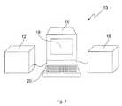
- FIG. 1is a schematic view of an example of an improved system for making a dental restoration
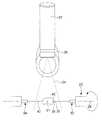
- FIG. 2is a schematic perspective view showing internal components of the scanner of FIG. 1 ;
- FIG. 3is schematic front view showing the scanner scanning a model
- FIG. 4is a schematic side view showing the scanner scanning a model
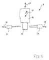
- FIG. 5is a schematic view showing the mill of the system of FIG. 1 .
- a model of the dental restorationis shaped directly in the client's mouth, then, the model is scanned, and the dental restoration is milled from a bloc based on the model's scan data. All is done in the dentist's office while the patient is waiting. The dental restoration can then be applied to the patient in a single visit.
- Types of dental restorationswhich can be made in this manner include dentinal pins, root pins, inlays and onlays.
- the present improvementsadvantageously make use of a model of the restoration shaped directly in the patient's mouth. This helps maintaining a minimal amount of manipulation from the shaping of the model to the milling of the restoration and can reduce the risks of error. Further, by shaping the model directly in the patient's mouth, the dentist can verify that the model does not interfere with other teeth when the jaw of the patient is closed.
- the dental tissue to which the dental restoration is to be appliedis prepared by defining a tapered recess therewithin.
- a hardening compoundis then applied to the tapered recess in vivo by the dentist, and the compound is hardened.
- the modelcan be made of many types of hardening compounds.
- One example of such a materialis a material which hardens under ultraviolet radiation.
- the hardening materialis non-adhesive, in order to be easily removable, and can be removed due to the tapered shape of the recess in the dental tissue.
- a layer of adhesion-preventing compoundcan be applied to the dental tissue prior to application of the hardening compound to prevent adhesion between the hardening compound and the dental tissue.
- the resulting modelwill typically be slightly smaller than the volume of the missing dental tissue. This can be beneficial.
- Dental restorationstypically require application of an adhesive to adhere the dental restoration to the dental tissue.
- the layer of adhesivehas a thickness, and if the dental restoration is of the exact shape and size than the missing dental tissue, the thickness of the adhesive may cause the dental restoration to not properly fit the tapered recess. If just the right amount of shrinkage occurs during hardening, the model may be sized just perfectly to allow for the thickness of the layer of adhesive. The dental restoration can then be made with the exact size and shape than the model and it will be ready to be applied to the patient using a layer of adhesive.
- a way of obtaining a model which has the right size to allow for the layer of adhesive when the hardening compound does not shrink during hardeningis to apply a layer of a spacing compound having the thickness of a layer of adhesive to the surface of the tapered recess before applying the hardening compound.
- the resulting modelwill have the volume of the missing dental tissue minus the thickness of the spacing compound.
- the spacing compoundcan advantageously be a non-adhesive compound to help prevent unwanted adhesion between the model and the dental tissue in cases where this can occur.
- the modeldoes not allow a sufficient spacing with the dental tissue for a layer of adhesive, it is also possible to electronically modify the 3D image of the scanned model to offset the surfaces which will be in contact with the dental tissue.
- the surfaces of the dental restoration or model which are adjacent the dental tissueare referred to herein by the term adhesion surfaces.
- the dental restorationcan then be based on the electronically modified image and be adapted for the layer of adhesive.
- the modelis hardened, it is removed from the patient's mouth. This is possible when the recess in the dental tissue is tapered because the resulting model has a counter-taper shape.
- FIG. 1shows an example of a system 10 which can be used in a dentist's office to scan the model and replicate the 3D image of the model obtained from the scan in a block of durable dental restoration material by milling.
- the system 10includes an optical scanner 12 , a computer 14 , and a mill 16 .
- the computer 14is connected both to the optical scanner 12 and to the mill 16 .
- the componentscan be provided in separate rooms or in a same room, in the dentist's office.
- the scanner 12 and computer 14can be provided in the patient's room, and the mill 16 can be placed in another room, to avoid the patient to be encumbered by noise emitted during milling.
- the scanner, computer, and millcan be provided together in a single, stand-alone unit.
- the computer 14can have a display 18 to allow visualizing the 3D model obtained by the scanner 12 .
- the computer 14has a user interface 20 which can be a keyboard, or which can alternately be a touch screen. It is preferred that the user interface 20 be as simple as possible to render the system 10 as easy as possible to use.
- the display 18can indicate to place the model in the scanner 12 .
- the computer 14detects that the model is positioned in the scanner 12 , the display 18 can request an input from the user to start the replicating process.
- the usercan respond using the user interface 20 , and the computer can command the scanner 12 to start scanning the model.
- the computer 14can be connected to the mill 16 by a TCP-IP Ethernet connection, for example.
- a 3D graphic representation of the modelis obtained.
- the 3D graphic representation of the modelcan be displayed on the display 18 .
- the usercan use the user interface 20 to interact with the computer 14 .
- the computer 14can propose a block of the durable dental restoration material having a sufficient size for the dental restoration to be milled in it.
- Three or four distinct sizes of blockscan be used, for example, and the computer 14 can propose to select one of these distinct sizes.
- the proposed blockis indicated on the display 18 .
- the usercan then select the proposed size of block and place it in the mill 16 .
- the computer 14creates a milling path based on the 3D graphic representation of the model, knowing the size of the block.
- the milling pathis communicated to the mill, and the mill can then mill the dental restoration from the block. Once the milling of the dental restoration is finished the dental restoration can be applied to the patient which has been waiting. The patient can thus go home with his dental restoration and does not need to come again for another visit.
- the scanner 12is partially schematized in FIG. 2 .
- the scanner 12allows to reproduce the model in spatial coordinates (X,Y,Z).
- the scanner 12includes a model holder 20 in which the model 21 is held.
- a laser 22 capable of emitting a flat beam 24is used as a photo-emitter.
- a CMOS captor 26or CCD camera, is used as a photo-receptor to detect rays of the laser bean reflected off the model 21 as the model 21 is rotated about a rotation axis 28 on 360° by rotating the model holder 20 .
- the laser 22is power modulated and provides structured light to the captor 26 .
- the laser 22 and captor 26are mounted on a common frame (not shown), at a known distance from a center point 27 .
- the model holder 20is also mounted to the common frame.
- the captor 26is angularly offset from the laser beam by 50° to obtain an image of the laser beam transformed by the model 21 .
- the deviation of the laser beam detected by the captor 26allows to obtain the spatial coordinates of the surface of the model 21 .
- the angular position of the model holder 20is monitored.
- More datacan be obtained by relatively inclining the rotation axis 28 about a transversal pivot axis 30 , thus placing the rotation axis 28 in a second relative orientation 28 a .
- the relatively inclined rotation axis 28 acan be kept in the plane of the flat beam 24 .
- the relative inclinationcan be achieved either by changing the inclination of the tool holder 20 , or by changing the inclination of the laser 22 and captor 26 assembly, for example.
- the model 21can then be scanned again while rotating the model 21 by 360° around the inclined rotation axis 28 a to obtain additional information on the shape of the tip 25 .
- the rotation axis 28can be inclined into a third relative orientation 28 b to obtain additional information on the tip 23 , for example.
- scanning in more supplemental inclinationscan be advantageous.
- scanning only along the second relative orientation 28 a and the third relative orientation 28 bsuch as a +30° and ⁇ 30° for example, can be satisfactory.
- the inclination of the second relative orientation 28 acan be of up to 90° from the inclination of the third relative orientation 28 b , for example.
- the use of many distinct and various inclinationscan be advantageous in certain alternate configurations.
- the computercan be programmed in order to detect the presence of hidden areas of the model, and to automatically determine an appropriate inclination to view at least one of such hidden areas. This process can be repeated for remaining hidden areas and the model be scanned at different inclinations until there remains no hidden area on the model.
- the scanning resolution selectedcan be of 20 ⁇ m for a zone of 40 mm width and 12 mm height.
- the scannercan be gauged by scanning a block of known dimensions.
- the lasercan be replaced by an even source of light, and the captor can be replaced by two cameras spaced by a known distance and oriented toward the model area, in a stereo camera scanning approach instead of the laser scanning approach described above.
- the model holder 20includes a first holding pin member 32 and a second holding pin member 34 .
- the holding pin membersuse pins, or needles, to hold the model in order to hide as little surface as possible of the model.
- the first holding pin member 32is motor-driven for rotation.
- the motoris a servo-motor and has an optical encoder which provides angular orientation data to the computer 18 .
- the angular orientation datais used in obtaining the 3D graphic representation.
- the first holding pin member 32has a Y shaped needle tip 36 including two splayed holding pins 38 , 40 .
- the first holding pin member 32is opposed to a second holding pin member 34 .
- the second holding pin member 34can be journalled in order to be freely rotatable around the rotation axis 28 .
- the second holding pin member 34can include a single holding pin 42 at its tip.
- One or both holding pin members 32 , 34can be axially displaceable and resiliently biased toward the other holding pin member to allow positioning of the model therebetween and releasing the resiliently biased holding pin member to hold the model.
- the bias compressive force exerted by the holding pin members on the model 21can advantageously be selected to allow slight penetration of the holding pins 38 , 40 , of the first holding pin member 32 into the model 21 , to ensure rotation of the model 21 when the motor driven holding pin member 32 is rotated.
- the following stepscan be followed. If modifications are to be made to the 3D graphic representation, to obtain a better fit with the restoration, or to provide a spacing for the layer of adhesive, they can be made electronically. This process can be partially automated, or entirely user decided.
- the 3D graphic representation of the modelthen becomes a 3D graphic representation of the dental restoration to be milled.
- the systemcan propose a block of sufficient dimensions to contain the dental restoration.
- the computeris then told which block has been selected.
- An algorithmcan then verify if it is possible to define a milling path based on the desired 3D graphic representation in the selected block. If the verification is negative, the display 18 can indicate to the user to place a larger block in the machine. If this verification is positive, the computer can define the trajectories of the various axes of the mill.
- FIG. 5schematically depicts an example of a mill 16 which can be used.
- the mill 16has a controller (not shown) which can operate the mill in accordance with the milling path determined by the computer 14 .
- the millhas 4 axes.
- the block 44 to millis held in a block holder 46 .
- the block holder 46is axially movable along a first axis 48 , and is pivotable along a second, transversal axis 50 to change the angle of the block 44 .
- Two milling tools 52 , 54are used, each milling tool being axially displaceable along a respective axis 56 , 58 .
- the step of millingis done while the patient is waiting, it is sought to minimize the time it takes to mill the dental restoration out from the block 44 .
- Speedis gained in this case by using two milling tools 52 , 54 which work at the same time, but on opposite sides of the block.
- An algorithmpreferably optimizes the positioning of the block to allow efficient access thereto by the milling tools 52 , 54 .
- the block 44is preferably made of a durable dental restoration material, such as ceramic, gold or titanium. Ceramic is preferred.
- the type of milling tool useddepends on the material of the block 44 used. So does the rotation speed and the feed rate of the tools.
- all the components of the millare impervious to the cutting fluid used. Impervious and extensible cowls can be used to protect mobile components from cutting fluid incursion.
- Gauging of the axes 48 , 50 , 56 , 58can be realized using a block of known dimensions. In this manner, coordinate systems of the different axes can be combined in a global coordinate system.
- a gauging procedurecan be presented on the display 18 ( FIG. 1 ), to guide the user step-by-step. Maintenance procedures can advantageously be simplified.
- Correspondence between axescan be done a single time, or periodically, whereas adjustment gauging is done at each time a tool is changed.
- the computercan be programmed to automatically calculate the lifespan of the milling tools and notify the user when a tool needs to be changed.
Landscapes
- Health & Medical Sciences (AREA)
- Life Sciences & Earth Sciences (AREA)
- Oral & Maxillofacial Surgery (AREA)
- Dentistry (AREA)
- Epidemiology (AREA)
- Animal Behavior & Ethology (AREA)
- General Health & Medical Sciences (AREA)
- Public Health (AREA)
- Veterinary Medicine (AREA)
- Optics & Photonics (AREA)
- Physics & Mathematics (AREA)
- Engineering & Computer Science (AREA)
- Manufacturing & Machinery (AREA)
- Dental Tools And Instruments Or Auxiliary Dental Instruments (AREA)
Abstract
Description
Claims (19)
Priority Applications (1)
| Application Number | Priority Date | Filing Date | Title |
|---|---|---|---|
| US11/730,681US7835558B2 (en) | 2006-04-03 | 2007-04-03 | Method and system for making dental restorations |
Applications Claiming Priority (2)
| Application Number | Priority Date | Filing Date | Title |
|---|---|---|---|
| US74415806P | 2006-04-03 | 2006-04-03 | |
| US11/730,681US7835558B2 (en) | 2006-04-03 | 2007-04-03 | Method and system for making dental restorations |
Publications (2)
| Publication Number | Publication Date |
|---|---|
| US20070243503A1 US20070243503A1 (en) | 2007-10-18 |
| US7835558B2true US7835558B2 (en) | 2010-11-16 |
Family
ID=38561374
Family Applications (1)
| Application Number | Title | Priority Date | Filing Date |
|---|---|---|---|
| US11/730,681Active2029-08-05US7835558B2 (en) | 2006-04-03 | 2007-04-03 | Method and system for making dental restorations |
Country Status (2)
| Country | Link |
|---|---|
| US (1) | US7835558B2 (en) |
| CA (1) | CA2583949C (en) |
Cited By (3)
| Publication number | Priority date | Publication date | Assignee | Title |
|---|---|---|---|---|
| US20120156965A1 (en)* | 2010-12-20 | 2012-06-21 | Weyrauch Jens | Method and apparatus for the production of extraoral dental prostheses |
| US20120324731A1 (en)* | 2010-03-09 | 2012-12-27 | Tekno Replik Inc. | Method and system for making dental restorations |
| US11823376B2 (en) | 2018-05-16 | 2023-11-21 | Benevis Informatics, Llc | Systems and methods for review of computer-aided detection of pathology in images |
Families Citing this family (8)
| Publication number | Priority date | Publication date | Assignee | Title |
|---|---|---|---|---|
| WO2008051129A1 (en) | 2006-10-27 | 2008-05-02 | Nobel Biocare Services Ag | A dental impression tray for use in obtaining an impression of a dental structure |
| EP2079394B1 (en) | 2006-10-27 | 2016-05-18 | Nobel Biocare Services AG | Method and apparatus for obtaining data for a dental component and a physical dental model |
| WO2008131159A1 (en)* | 2007-04-20 | 2008-10-30 | 3M Innovative Properties Company | Dental restoration design using temporizations |
| DE102009001428A1 (en) | 2009-03-10 | 2010-09-16 | Sirona Dental Systems Gmbh | Processing machine for a workpiece, in particular for the production of dental prostheses or models thereof and methods |
| US10133244B2 (en) | 2012-06-13 | 2018-11-20 | James R. Glidewell Dental Ceramics, Inc. | Chair side mill for fabricating dental restorations |
| SE1400260A1 (en) | 2014-05-22 | 2015-11-23 | Arrangements and method for manufacturing individually designed items such as dental restorations | |
| DE102016208794B3 (en)* | 2016-05-20 | 2017-10-05 | Sirona Dental Systems Gmbh | Computer-aided manufacturing method for dental prosthesis part or dental auxiliary element |
| EP3815645A1 (en) | 2019-11-01 | 2021-05-05 | DENTSPLY SIRONA Inc. | Dental machining system for predicting the wear condition of a dental tool |
Citations (17)
| Publication number | Priority date | Publication date | Assignee | Title |
|---|---|---|---|---|
| US4575805A (en) | 1980-12-24 | 1986-03-11 | Moermann Werner H | Method and apparatus for the fabrication of custom-shaped implants |
| US5385471A (en) | 1993-01-05 | 1995-01-31 | Chuen; Ng T. | Cerec inlay holder and inserter |
| US5549476A (en)* | 1995-03-27 | 1996-08-27 | Stern; Sylvan S. | Method for making dental restorations and the dental restoration made thereby |
| US5813859A (en) | 1997-01-23 | 1998-09-29 | Hajjar; Victor J. | Method and apparatus for tooth restoration |
| US6375729B1 (en) | 1999-03-19 | 2002-04-23 | Jeneric/Pentron, Inc. | Machinable glass-ceramics |
| WO2002074183A1 (en) | 2001-03-21 | 2002-09-26 | Michel Valery | Method for producing dental restoration elements |
| US6527550B1 (en)* | 2000-02-15 | 2003-03-04 | Victor J. Hajjar | Apparatus and method for producing a dental prosthetic with a device having a linear rotary bearing |
| US20030222366A1 (en) | 2001-12-21 | 2003-12-04 | Ivan Stangel | Production of dental restorations and other custom objects by free-form fabrication methods and systems therefor |
| US6685470B2 (en)* | 1999-05-14 | 2004-02-03 | Align Technology, Inc. | Digitally modeling the deformation of gingival tissue during orthodontic treatment |
| US20040245664A1 (en) | 2000-07-21 | 2004-12-09 | Carlino Panzera | Method of making a dental restoration |
| US20040254667A1 (en) | 2003-06-13 | 2004-12-16 | Ivoclar Vivadent Ag | Method for producing dental restoration and apparatus therefor |
| US6835067B2 (en) | 2002-03-11 | 2004-12-28 | Jeffrey Dorfman | Prefabricated dental inlay forms for use in fillings |
| US20050064360A1 (en) | 2003-02-26 | 2005-03-24 | Huafeng Wen | Systems and methods for combination treatments of dental patients |
| US20050110177A1 (en) | 1998-07-10 | 2005-05-26 | Schulman Martin L. | Mass production of shells and models for dental restorations produced by solid free-form fabrication methods |
| US20050115460A1 (en) | 1994-05-31 | 2005-06-02 | Petticrew Richard W. | Method for molding dental restorations and related apparatus |
| US20050170315A1 (en) | 2004-01-20 | 2005-08-04 | Strobel Wolfgang M. | System, method, computer program product and apparatus for producing dental restorations |
| US20050186540A1 (en) | 2004-02-24 | 2005-08-25 | Eldad Taub | Method and system for designing and producing dental prostheses and appliances |
Family Cites Families (1)
| Publication number | Priority date | Publication date | Assignee | Title |
|---|---|---|---|---|
| US7247249B2 (en)* | 2004-01-15 | 2007-07-24 | The Gillette Company | Method of treating razor blade cutting edges |
- 2007
- 2007-04-03CACA2583949Apatent/CA2583949C/enactiveActive
- 2007-04-03USUS11/730,681patent/US7835558B2/enactiveActive
Patent Citations (18)
| Publication number | Priority date | Publication date | Assignee | Title |
|---|---|---|---|---|
| US4575805A (en) | 1980-12-24 | 1986-03-11 | Moermann Werner H | Method and apparatus for the fabrication of custom-shaped implants |
| US5385471A (en) | 1993-01-05 | 1995-01-31 | Chuen; Ng T. | Cerec inlay holder and inserter |
| US20050115460A1 (en) | 1994-05-31 | 2005-06-02 | Petticrew Richard W. | Method for molding dental restorations and related apparatus |
| US5549476A (en)* | 1995-03-27 | 1996-08-27 | Stern; Sylvan S. | Method for making dental restorations and the dental restoration made thereby |
| US5813859A (en) | 1997-01-23 | 1998-09-29 | Hajjar; Victor J. | Method and apparatus for tooth restoration |
| US6641340B1 (en) | 1997-01-23 | 2003-11-04 | Victor J. Hajjar | Apparatus and method for machining a prosthetic tooth restoration |
| US20050110177A1 (en) | 1998-07-10 | 2005-05-26 | Schulman Martin L. | Mass production of shells and models for dental restorations produced by solid free-form fabrication methods |
| US6375729B1 (en) | 1999-03-19 | 2002-04-23 | Jeneric/Pentron, Inc. | Machinable glass-ceramics |
| US6685470B2 (en)* | 1999-05-14 | 2004-02-03 | Align Technology, Inc. | Digitally modeling the deformation of gingival tissue during orthodontic treatment |
| US6527550B1 (en)* | 2000-02-15 | 2003-03-04 | Victor J. Hajjar | Apparatus and method for producing a dental prosthetic with a device having a linear rotary bearing |
| US20040245664A1 (en) | 2000-07-21 | 2004-12-09 | Carlino Panzera | Method of making a dental restoration |
| WO2002074183A1 (en) | 2001-03-21 | 2002-09-26 | Michel Valery | Method for producing dental restoration elements |
| US20030222366A1 (en) | 2001-12-21 | 2003-12-04 | Ivan Stangel | Production of dental restorations and other custom objects by free-form fabrication methods and systems therefor |
| US6835067B2 (en) | 2002-03-11 | 2004-12-28 | Jeffrey Dorfman | Prefabricated dental inlay forms for use in fillings |
| US20050064360A1 (en) | 2003-02-26 | 2005-03-24 | Huafeng Wen | Systems and methods for combination treatments of dental patients |
| US20040254667A1 (en) | 2003-06-13 | 2004-12-16 | Ivoclar Vivadent Ag | Method for producing dental restoration and apparatus therefor |
| US20050170315A1 (en) | 2004-01-20 | 2005-08-04 | Strobel Wolfgang M. | System, method, computer program product and apparatus for producing dental restorations |
| US20050186540A1 (en) | 2004-02-24 | 2005-08-25 | Eldad Taub | Method and system for designing and producing dental prostheses and appliances |
Non-Patent Citations (2)
| Title |
|---|
| McLarent et al., Fabrication of conservative ceramic restorations using copy-milling technology, Special reprint from Quintessence of Dental Technology, 1994, vol. 17. |
| Ringer, The essentials for placing indirect composite inlays and onlays, Cosmetic Dentistry, Oral Health, May 2003. |
Cited By (6)
| Publication number | Priority date | Publication date | Assignee | Title |
|---|---|---|---|---|
| US20120324731A1 (en)* | 2010-03-09 | 2012-12-27 | Tekno Replik Inc. | Method and system for making dental restorations |
| US8857058B2 (en)* | 2010-03-09 | 2014-10-14 | Dental Wings Inc. | Method and system for making dental restorations |
| US20120156965A1 (en)* | 2010-12-20 | 2012-06-21 | Weyrauch Jens | Method and apparatus for the production of extraoral dental prostheses |
| US11823376B2 (en) | 2018-05-16 | 2023-11-21 | Benevis Informatics, Llc | Systems and methods for review of computer-aided detection of pathology in images |
| US12254628B2 (en) | 2018-05-16 | 2025-03-18 | Benevis Informatics, Llc | Systems and methods for review of computer-aided detection of pathology in images |
| US12272062B2 (en) | 2018-05-16 | 2025-04-08 | Benevis Informatics, Llc | Systems and methods for review of computer-aided detection of pathology in images |
Also Published As
| Publication number | Publication date |
|---|---|
| US20070243503A1 (en) | 2007-10-18 |
| CA2583949C (en) | 2014-07-08 |
| CA2583949A1 (en) | 2007-10-03 |
Similar Documents
| Publication | Publication Date | Title |
|---|---|---|
| US7835558B2 (en) | Method and system for making dental restorations | |
| EP2345387B1 (en) | Manufacture of a dental model | |
| KR102114015B1 (en) | Virtually designing a customized healing abutment | |
| Schaefer et al. | Impact of digital impression techniques on the adaption of ceramic partial crowns in vitro | |
| CN104519825B (en) | An automatic intraoral dental preparation device for local dental restoration or peripheral nerve restoration | |
| US6190171B1 (en) | Method and apparatus for tooth restoration | |
| CA2699791C (en) | Method for producing a crown for an implant abutment | |
| US7695281B2 (en) | Method and system for designing a dental replacement | |
| US20050142517A1 (en) | System for producing a dental implant and method | |
| JP4726413B2 (en) | Methods for three-dimensional measurement and digitization of gypsum molds or positive models | |
| JPWO2009035142A1 (en) | Dental prosthesis measurement processing system | |
| US20060253215A1 (en) | Method, computer, computer program and computer-readable medium relating to the examination of data records for dental prosthesis parts | |
| WO2013124452A1 (en) | Virtually reducing and milling artificial teeth | |
| WO2007127804A2 (en) | Computer machined dental tooth system and method | |
| US20150289954A1 (en) | Computer fabrication of dental prosthetics | |
| JP2010538302A (en) | 3D preview system and method | |
| WO2011030906A1 (en) | Tooth-cutting device and method | |
| US8857058B2 (en) | Method and system for making dental restorations | |
| ES2295375T3 (en) | PROCEDURE OF REALIZATION OF DENTAL RESTORATION ELEMENTS. | |
| CN104116569A (en) | Computer fabrication of dental prosthetic | |
| JP2008043566A (en) | Manufacturing support program of data for cut processing anchor tooth opposing face of dental prosthesis | |
| HK1147413A (en) | Dental inlay graft measuring/machining system | |
| HK1071682B (en) | Method for producing dental restoration elements |
Legal Events
| Date | Code | Title | Description |
|---|---|---|---|
| AS | Assignment | Owner name:TEKNO REPLIK INC., CANADA Free format text:ASSIGNMENT OF ASSIGNORS INTEREST;ASSIGNORS:GAGNON, JEAN;SAINDON, CHRISTIAN;REEL/FRAME:019523/0980 Effective date:20070627 | |
| STCF | Information on status: patent grant | Free format text:PATENTED CASE | |
| FPAY | Fee payment | Year of fee payment:4 | |
| AS | Assignment | Owner name:DENTAL WINGS INC., CANADA Free format text:ASSIGNMENT OF ASSIGNORS INTEREST;ASSIGNOR:TEKNO REPLIK INC.;REEL/FRAME:035032/0548 Effective date:20150217 | |
| FEPP | Fee payment procedure | Free format text:PAYOR NUMBER ASSIGNED (ORIGINAL EVENT CODE: ASPN); ENTITY STATUS OF PATENT OWNER: LARGE ENTITY | |
| MAFP | Maintenance fee payment | Free format text:PAYMENT OF MAINTENANCE FEE, 8TH YR, SMALL ENTITY (ORIGINAL EVENT CODE: M2552) Year of fee payment:8 | |
| FEPP | Fee payment procedure | Free format text:ENTITY STATUS SET TO UNDISCOUNTED (ORIGINAL EVENT CODE: BIG.); ENTITY STATUS OF PATENT OWNER: LARGE ENTITY | |
| MAFP | Maintenance fee payment | Free format text:PAYMENT OF MAINTENANCE FEE, 12TH YEAR, LARGE ENTITY (ORIGINAL EVENT CODE: M1553); ENTITY STATUS OF PATENT OWNER: LARGE ENTITY Year of fee payment:12 | |
| AS | Assignment | Owner name:INSTITUT STRAUMANN AG, SWITZERLAND Free format text:NUNC PRO TUNC ASSIGNMENT;ASSIGNOR:DENTAL WINGS, INC.;REEL/FRAME:069674/0613 Effective date:20241212 |